Embed Size (px)
Citation preview


Thank you for purchasing a Honda Lawn Tractor.
This manual covers the operation and maintenance of the Honda HT4213 Lawn Tractor, type SA (side discharge).
Honda Motor Co., Ltd. reserves the right to make changes at any time without notice and without incurring any obligation.
No part of this publication may be reproduced without written permission.
This manual should be considered a permanent part of the lawn tractor and should remain with the lawn tractor when sold.
Pay special attention to statements preceded by the following words;
ADANGER: Indicates severe personal injury or death will result if in- structions are not followed.
m Indicates a strong possibility of severe personal injury or death if instructions are not followed.
CAUTION: Indicates a possibility qf personal injury or equipment damage if instructions are not followed.
NOTE: Gives helpful information.
If a problem should arise, or if you have any questions about the lawn trac- tor, consult an authorized Honda Lawn Tractor dealer. Honda lawn tractors are designed to give safe and dependable service if operated according to instructions.
m Operating a,lawn tractor requires special effort to ensure the safe- ty of the operator and the safety of others. Read and understand this Owner’s Manual before operating the lawn tractor; failure to do so could result in per- sonal injury or equipment damage.
It is illegal in some areas to operate a gasoline engine without a U.S.D.A. qualified spark arrester; check local laws and regulations. You can pur- chase an optional spark arrester for this lawn tractor from your authorized Honda Power Equipment dealer.
HONDA MOTOR CO., LTD. 1986, ALL RIGHTS RESERVED

CONTENTS
1. SAFETY INSTRUCTIONS . . . . . . . . . . . . . . . . . . . . . . . . . . . . . . . . . . . . . . . . . . . . . . . . . . . . . . . 3
2. COMPONENT IDENTIFICATION . . . . . . . . . . . . . . . . . . . . . . . . . . . . . . . . . . . . . . . . . . . . . . 8
3. CONTROLS . . . . . . . . . . . . . . . . . . . . . . . . . . . . . . . . . . . . . . . . . . . . . . . . . . . . . . . . . . . . . . . . . . . . . . . . . 10
4. PRE-OPERATION CHECKS . . . . . . . . . . . . . . . . . . . . . . . . . . . . . . . . . . . . . . . . . . . . . . . . . . . . . 15
5. OPERATION . . . . . . . . . . . . . . . . . . . . . . . . . . . . . . . . . . . . . . . . . . . . . . . . . . . . . . . . . . . . . . . . . . . . . . . . 26
-I l Starting the engine
l Mowing
l Stopping the engine
l High altitude operation
6. TRANSPORTIklG/STORAGE . . . . . . . . . . . . . . . . . . . . . . . . . . . . . . . . . . . . . . . . . . . . . . . . . . . 35.
7. MAINTENANCE ~.................................................................. 40
8. WIRING DIAGRAM . . . . . . . . . . . . . . . . . . . . . . . . . . . . . . . . . . . . . . . . . . . . . . . . . . . . . . . . . . . . . . . 56
9. TROUBLESHOOTING . . . . . . . . . . . . . . . . . . . . . . . . . . . . . . . . . . . . . . . . . . . . . . . . . . . . . . . . . . . . 57
i 0. SPECIFICATIONS . . . . . . . . . . . . . . . . . . . . . . . . . . . . . . . . . . . . . . . . . . . . . . . . . . . . . . . . . . . . . . . . . 60
11. WARRANTY SERVICE . . . . . . . . . . . . . . . . . . . . . . . . . . . . . . . . . . . . . . . . . . . . . . . . . . . . . . . . . . . 61
2
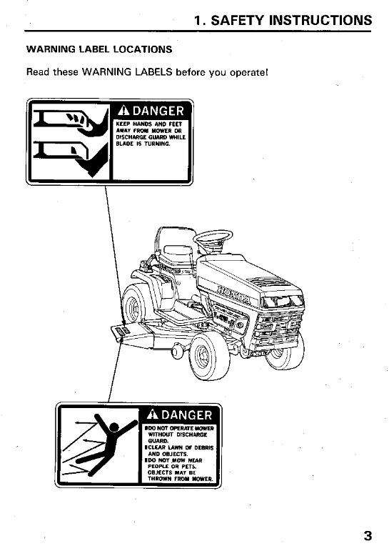
1. SAFETY INSTRUCTIONS
WARNING LABEL LOCATIONS
Read these WARNING LABELS before you operate!
3
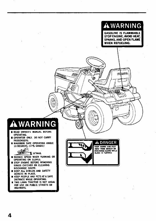
I READ OWNER’S MANUAL BEFORE OPERATING.
I OPERATOR ONLY. DO NOT CARRY PASSENGERS.
I MAXIMUM SAFE OPERATING ANGLE 10 DEGREES. (17% GRADE)
lo-MAX.
G REDUCE SPEED WHEN TURNING OR OPERATING ON SLOPES.
I STOP ENGINE BEFORE REMOVING GRASS CATCHER OR CLEANING DISCHARGE CHUTE.
I KEEP ALL SHIELDS AND SAFETY DEVICES IN PLACE.
I KEEP PEOPLE AND PETS AT A SAFE DISTANCE WHILE OPERATING.
I THIS LAWN TRACTOR IS NOT LEGAL FOR USE ON PUBLIC STREETS OR HIGHWAYS.
GASOLINE IS FLAMMABLE STOP ENGINE, AVOID HEAT, SPARKS, AND OPEN FLAME WHEN REFUELING.
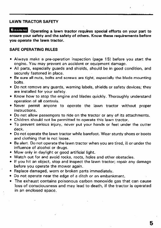
LAWN TRACTOR SAFETY
imm Operating a lawn tractor requires special efforts on your part to ensure your safety and the safety of others. Know these requirements before you operate the lawn tractor.
SAFE OPERATING RULES
l Always make a pre-operation inspection (page 15) before you start the engine. You may prevent an accident or equipment. damage.
l All parts, especially guards and shields, should be in good condition, and securely fastened in place.
l Be sure all nuts, bolts and screws are tight, especially the blade mounting bolts.
l Do not remove any guards, warning labels, shields or safety devices; they are installed for your safety.
l Know how to stop the engine and blades quickly. Thoroughly understand operation of all controls.
l Never permit anyone to operate the lawn tractor without proper instructions.
l Do not allow passengers to ride on the tractor or any of its attachments. l Children should not be permitted to operate this lawn tractor. l To prevent serious injury, never put your hands or feet under the cutter
deck. l Do not operate the lawn tractor while barefoot. Wear sturdy shoes or boots
and clothing that is not loose. l Be alert. Do not operate the lawn tractor when you are tired, ill or under the
influence of alcohol or drugs. l Mow only in daylight or good artificial light. l Watch out for and avoid rocks, roots, holes and other obstacles. l If you hit an object, stop and inspect the lawn tractor; repair any damage
before you operate the mower again. l Replace damaged, worn or broken parts immediately. l Do not operate near the edge of a ditch or an embankment.
l The exhaust contains poisonous carbon monoxide gas that can cause loss of consciousness and may lead to death, if the tractor is operated in an enclosed space.
5
BEFORE MOWING
l Before mowing, always clear the lawn of stones, sticks or other debris. These objects could be thrown out by the spinning blade and cause an in- jury or equipment damage.
l Select a safe operating speed (gear position) for the area to be mowed. 5th gear should be used only while driving to and from the storage area.
l Always ensure that the area in front of and behind the lawn tractor is clear of people, pets and debris before starting.
l Be very careful when you operate the lawn tractor in Reverse. l Do not mow in Reverse unless it is absolutely necessary. l Use extra care when pulling a trailer or when using optional attachments.
a. Be sure that any accessories (trailer hitch, etc.) are securely mounted, and that they do not interfere with the safe operation of the tractor.
b. Reduce operating speeds when using attachments, and limit loads to those you can safely control.
c. Use care when backing, and avoid making sharp turns.
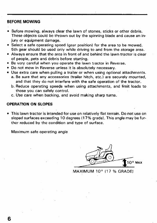
OPERATION ON SLOPES
l This lawn tractor is intended for use on relatively flat terrain. Do not use on sloped surfaces exceeding 10 degrees (17% grade). This angle may be fur- ther reduced by the condition and type of surface.
Maximum safe operating angle
MAX
MAXIMUM loo (17 % GRADE)
6
.* If mowing on a sloping surface, always drive up and down the face of the grade. Never turn or drive across the face of the slope.
l To prevent loss of control or overturning, always reduce speed and exer- cise extreme caution when operating on sloping or uneven surfaces.
l Avoid turning or stopping on sloping surfaces; see page 31 for special instructions.
l Do not back down or rapidly accelerate up a sloping surface; see page 31 for special instructions.
CLEANING AND STORAGE
l Leaves, grass clippings, oil and other combustible materials can be- come a fire hazard. Be sure to keep the engine compartment, the upper cutter deck surfaces and the belt and pulley areas clean.
l Damp, decomposing grass clippings generate heat-and can become a fire hazard.
l To reduce the possibility of fire, allow the engine and exhaust system to cool before storing the mower in an enclosed space or near com- bustible materials.
7
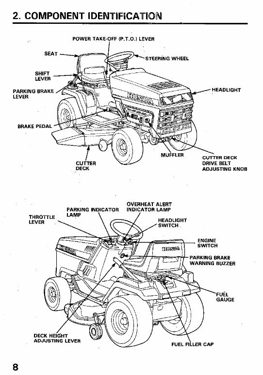
2. COMPONENT IDENTIFUCATION
POWER TAKE-OFF (P.T.O.) LEVER I
PARKING BRAKE LEVER
BRAKE PEDAL
THRQ
PARKING INDICATOR INDICATOR LAMP
~~-bTTLE LAlM: LEVER \
=F-L’ ‘STEERING WHEEL
?99?!?% / HEADLIGHT
\- MUFFLER CUTTER DECK
CUfTER DRIVE BELT DECK ADJUSTING KNOB
OVERHEAT ALERT
ENGINE ^._.._^. .
DECK HEkHT ADJUSTING LEVER
FUEL FILLER CAP
8
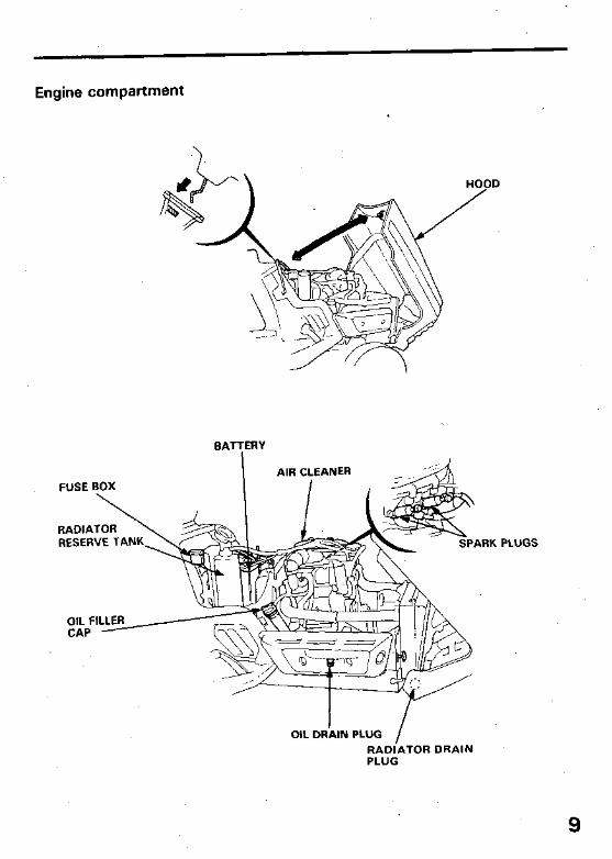
Engine compartment
BATTERY
AIR CLEANER FUSE BOX
RESERVE TANK,
OIL FI CAP
PLUGS
OIL DRilN PLUG /
RADIATOR DRAIN PLUG
9
3, CONTROLS
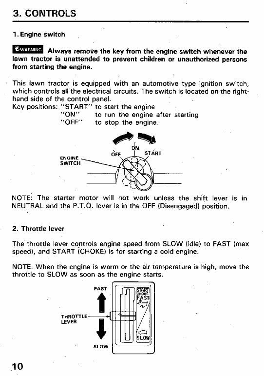
1. Engine switch
m Always remove the key from the engine switch whenever the lawn tractor is unattended to prevent children or unauthorized persons from starting the engine.
This lawn tractor is equipped with an automotive type ignition switch, which controls all the electrical circuits. The switch is located on the right- hand side of the control panel. Key positions: “START” to start the engine
“ON” to run the engine after starting “OFF” to stop the engine.
dN ,
ENGINE SWITCH
NOTE: The starter motor will not work unless the shift lever is in NEUTRAL and the P.T.O. lever is in the OFF (Disengaged) position.
2. Throttle lever
The throttle lever cqntrols engine speed from SLOW (idle).to FAST (max speed), and START (CHOKE) is for starting a cold engine.
NOTE: When the engine is warm or the air temperature is high, move the throttle to SLOW as soon as the engine starts.
FAST
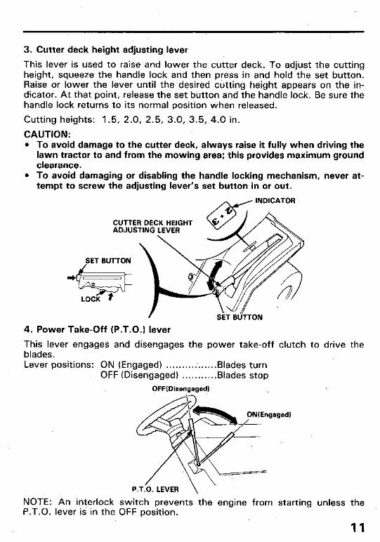
3. Cutter deck height adjusting lever
This lever is used to raise and lower the cutter deck. To adjust the cutting height, squeeze the handle lock and then press in and hold the set button. Raise or lower the lever until the desired cutting height appears on the in- dicator. At that pointi release the set button and the handle lock. Be sure the handle lock returns to its normal position when released.
Cutting heights: 1.5, 2.0, 2.5, 3.0, 3.5, 4.0 in.
CAUTION: l To avoid damage to the cutter deck, always raise it fully when driving the
lawn tractor to and from the mowing area; this provides maximum ground clearance.
l To avoid damaging or disabling the handle locking mechanism, never at- tempt to screw the adjusting lever’s set button in or out.
SET BUTTON
4. Power Take-Off (P.T.O.1 lever
This lever engages and disengages the power take-off clutch to drive the blades. Lever positions: ON (Engaged) . . . . . . . . . :. . . . . .Blades turn
OFF (Disengaged) . . . . . . . . . ..Blades stop
OFF(Disengaged)
P.T.O. LEVER
NOTE: An interlock switch prevents the engine from starting unless the P.T.O. lever is in the OFF position.
11

5. Shift lever
This lever is .used to select one of the five forward speeds, neutral, or reverse. The drive clutch automatically disengages while the lever is being moved. The clutch will then engage automatically when put into gear unless the brake pedal is depressed.
CAUTION: Bring the tractor to a complete stop before shifting from a for- ward speed to reverse, or from reverse to a forward speed. Shifting bet- ween forward and reverse speeds while the tractor is moving can cause transmission damage.
When shifting from one forward speed range to another while moving, do not force the shift lever and do not shift up or down more than one slot at a time. Do not operate the shift lever on slopes.
NOTE: The tractor will pull away from a stop in any speed range. No shifting is necessary.
5th speed is not recommended for mowing but may be used for driving the tractor from ‘one area to another.
12
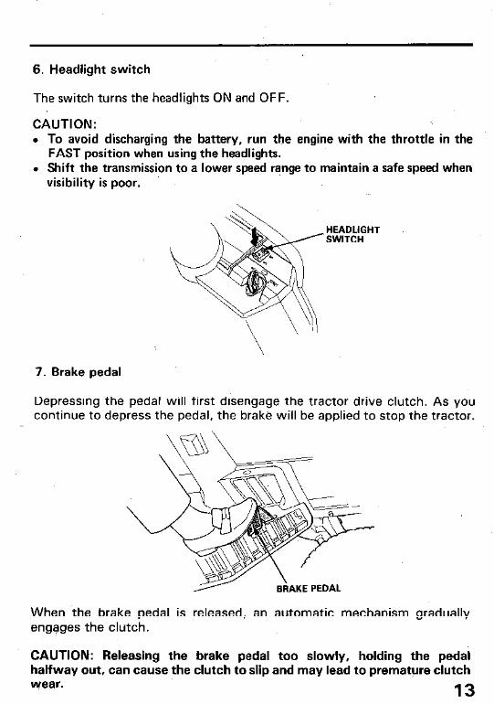
6. Headlight switch
The switch turns the headlights ON and OFF.
CAUTION: \
l To avoid discharging the battery, run the engine with the throttle in the FAST position when using the headlights.
l Shift the transmission to a lower speed range to maintain a safe speed when visibility is poor.
HEADLIGHT ‘SWITCH
7. Brake pedal
Depressing the pedal will first disengage the tractor drive clutch. As you continue to depress the pedal, the brake will be applied to stop the tractor.
When the brake pedal is released, an automatic mechanism gradually engages the clutch.
CAUTION: Releasing the brake pedal too slowly, holding the pedal halfway out, can cause the clutch to slip and may lead to premature clutch wear. 13

8. Parking brake lever
This lever is used to set the brake when the lawn tractor is parked. Pull the lever fully up until the ratchet locks, and be sure that the parking in- dicator lamp on the control panel is ON.
NOTE: The parking brake lever does not operate the automatic clutch. Always put the transmission in neutral, or turn off the engine switch before setting the parking brake. A warning buzzer will sound if the parking brake is ‘engaged while the transmission is in gear and the engine switch is ON.
Pull the lever up slightly and press the lever button, lower the lever while holding the button in. The parking indicator lamp should go off.
lami Operating the Pawn tractor with the parking brake set will result in severe damage to the brake lining, and coulb lead-to a complete brake system failure.
PARKING INDICATOR LAMP
BUTTON
WARNING BUZZER
14
4. PRE-OPERATPON CHECKS
For safe and efficient mowing, always make a pre-operation inspection before mowing:
m TD prevent accidentat start-up, remove the engine switch key, and disconnect the spark plug caps before performing the pre-operation inspection.
CAUTION: l Inspect with the Lawn Tractor on level ground. l Pull up the parking brake fully, set thb shift lever in “N (Neutral)” and
P.T.O. lever in “OFF” position, and inspect.
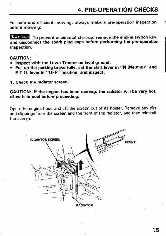
1. Check the radiator screen.
CAUTION: If the engine has been running, the radiator will be very hot; allow it to cool before proceeding.
Open the engine hood and lift the screen out of its’ holder. Remove any dirt and clippings from the screen and the front of the radiator, and then reinstall the’screen.
RADIATOR
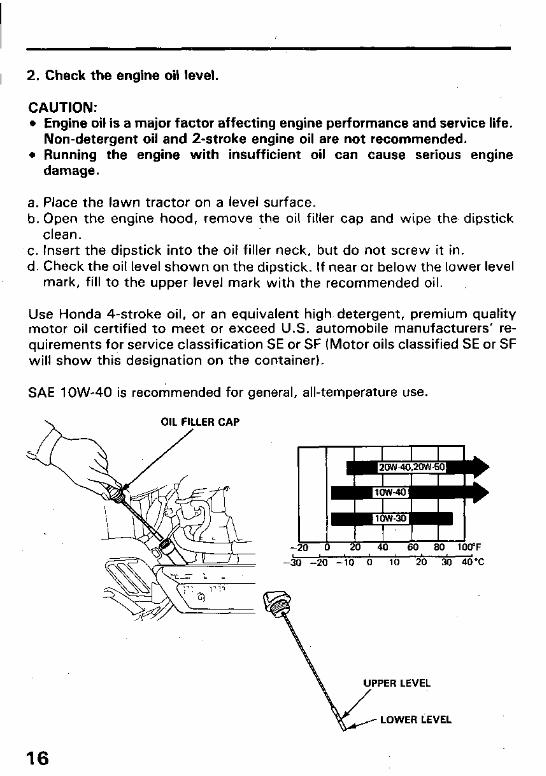
2. Check the engine oil level.
CAUTION: l Engine oil is a major factor affecting engine performance and service life.
Non-detergent oil and 2-stroke engine oil are not recommended. l Running the engine with insufficient oil can cause serious engine
damage.
a. Place the lawn tractor on a level surface. b. Open the engine hood, remove the oil filler cap and wipe the dipstick
clean. .c. Insert the dipstick into the oil filler neck, but do not screw it in. d. Check the oil level shown on the dipstick. If near or below the lower level
mark, fill to the upper level mark with the recommended oil.
Use Honda 4-stroke oil, or an equivalent high detergent, premium quality motor oil certified to meet or exceed U.S. automobile manufacturers’ re- quirements for service classification SE or SF (Motor oils classified SE or SF will show this designation on the container).
SAE low-40 is recommended for general, all-temperature use.
OIL FILLER CAP
UPPER LEVEL / v LOWER LEVEL
16
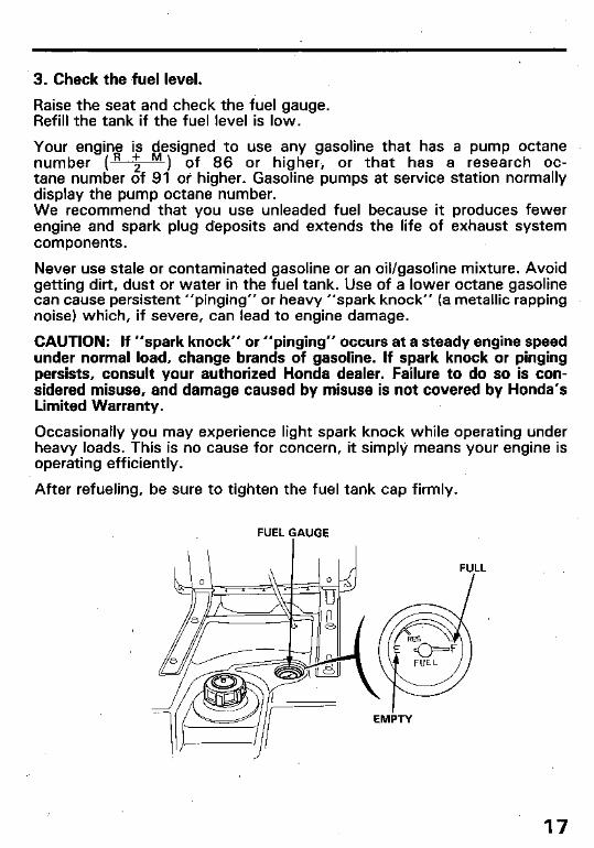
3. Check the fuel level.
Raise the seat and check the fuel gauge. Refill the tank if the fuel level is low.
Your engine is designed to use any gasoline that has a pump octane number (R ‘2 M ) of 86 or higher, or that has a research oc- tane number of 91 oi higher. Gasoline pumps at service station normally display the pump octane number. We recommend that you use unleaded fuel because it produces fewer engine and spark plug deposits and extends the life of exhaust system components.
Never use stale or contaminated gasoline or an oil/gasoline mixture. Avoid getting dirt, dust or water in the fuel tank. Use of a lower octane gasoline can cause persistent “pinging” or heavy “spark knock” (a. metallic rapping noise) which, if severe, can lead to engine damage.
CAUTION: If “spark knock” or “pinging” occurs at a steady engine speed under normal load, change brands of gasoline. If spark knock or pinging persists, consult your authorized Honda dealer. Failure to do so is con- sidered misuse, and damage caused by misuse is not covered by Honda’s Limited Warranty.
Occasionally you may experience light spark knock while operating under heavy loads. This is no cause for concern, it simply means your engine is operating efficiently.
After refueling, be sure to tighten the fuel tank cap firmly.
FUEL $AUGE
17

m l Gasoline is extremely flammable and is explosive under certain conditions. l Refuel in a well-ventilated area with the engine stopped. Do not smoke or
allow.flames or sparks in the area where the engine is refueled or where gasoline is stored.
l Do not overfill the fuel tank (there should be no fuel in the filler neck). After refueling, make sure the tank cap is closed properly and securely.
l Be careful not to spill fwel when refueling. Spilled fuel or fuel vapor may ig- nite. If any fuel is spilled, make sure the area is dry before starting the engine.
l Avoid repeated or prolonged contact with skin or breathing of vapor. KEEP OUT OF REACH .OF CHILDREN.
GASOLINES CONTAINING ALCOHOL
If you decide to use a gasoline containing alcohol (gasohol), be sure it’s octane rating is at least as high as that recommended by Honda. There are two types of “gasohol”: one containing ethanol, and the other containing methanol. Do not use gasohol that contains more than 10% ethanol. Do not use gasoline containing methanol (methyl or wood alcohol) that does not also contain
Y cosolvents and corrosion inhibitors for methanol. Never use gasoline contain- ing more than 5% methanol, even if it has cosolvents and corrosion inhibitors.
,NOTE: l Fuel system damage or engine performance problems resulting from the use
of fuels that contain alcohol is not covered under the warranty. Honda cannot endorse the use of fuels containing methanol since evidence of their suitability is as yet incomplete.
l Before buying fuel from an unfamiliar station, try to find out if the fuel con- tains alcohol, if it does, confirm the type and percentage of alcohol used. If you notice any undesirable operating symptoms while using a gasoline that contains alcohol, or one that you think contains alcohol, switch to ‘a gasoline that you know does not contain alcohol.
18
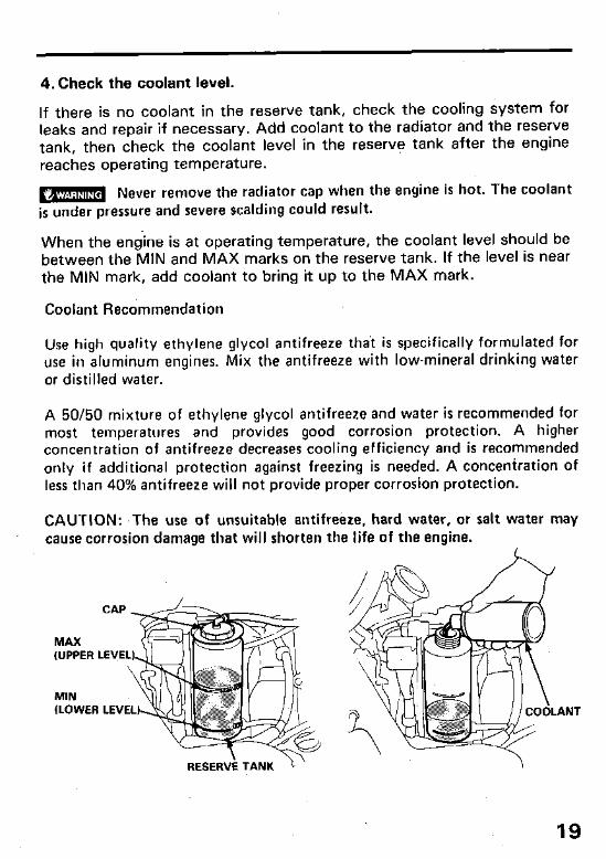
4. Check the coolant level.
If there is no coolant in the reserve tank, check the cooling system for leaks and repair if necessary. Add coolant to the radiator and the reserve tank, then check the coolant level in the reserve tank after the engine reaches operating temperature.
m Never remove the radiator cap when the is under pressure and severe scalding could result.
engine hot. The coolant
When the endine is at operating temperature, the coolant level should be between the MIN and MAX marks on the reserve tank. If the level is near the MIN mark, add coolant to bring it up to the MAX mark.
Coolant Recommendation
Use high quality ethylene glycol antifreeze that is specifically formulated for use in aluminum engines. Mix the antifreeze with low-mineral drinking water or distilled water.
A 50/50 mixture of ethylene glycol antifreeze and water is recommended for most temperatures and provides good corrosion protection. A higher concentration of antifreeze decreases cooling efficiency and is recommended only if additional protection against freezing is needed. A concentration of less than 40% antifreeze will not provide proper corrosion protection.
CAUTION: ,The use of unsuitable antifreeze, hard water, or salt water may cause corrosion damage that will shorten the life of the engine.
CAP
MAX (UPPER LEVE
MIN (LOWER LEVEL)
19

5. Check the air cleaner elements.
1. Remove the. two wing nuts to remove the air cleaner cover. 2. Remove the air cleaner elements.
If the elements are dirty, follow the cleaning procedure described page 43.
WING NUTS
AIR CLEANER COVER
on
6. Check brake lining wear.
AIR CLEANER
Inspect brake lining condition every time the lawn tractor is used.
Press firmly on the brake pedal with your hand and then check the position of the brake wear indicator. If the indicator is near the wear limit point, take the lawn tractor to an authorized Honda lawn tractor dealer for repair.
CAUTION: Under no circumstances should CAUTION: Under no circumstances should the lawn tractor be operated the brake lining is at the service limit. the brake lining is at the service limit.
if
BRAKE\ PEDAL /- BRAK; WEAR WEAR LIMIT POINT lNDlCATOR
20

7. Check the cutter deck drive belt.
1. Lower the cutter deck by using the cutter deck height adjusting lever, and open the engine hood.
2. Inspect the belt for wear or damage. If worn qr damaged, replace the belt as described on pages 50- 51.
SET BUTTON
3.. Check belt tension at the tensioner arm. The mark on the tensioner arm should align with the tension indicator. If not, turn the adjusting knob to align the mark with the indicator.
TENSIONER ARM BELT TENSION ADJUSTING
ALIGNMENT MARK
TENSION INDICATOR
21

8. Check the battery
Open the engine hood and check the battery electrolyte level. The electrolyte level must be maintained between the upper and ‘lower level lines on the side of the battery. If the electrolyte level is low, remove the battery filler caps and carefully add distilled water to the upper level line.
UPPER LEVEL LOWER LEVEL
l The battery gives off explosive gases; keep sparks, flames and cigaret- tes away. Provide adequate ventilation when charging or using batteries in an enclosed space.
l The battery contains sulfuric acid (electrolyte). Contact with skin or eyes may cause severe burns. Wear protective clothing and a face shield. - If electrolyte gets on your skin, flush with water. - If electrolyte gets in your eyes, flush with water for at least 15
minutes and call a physician immediately. l Electrolyte is poisonous.
- If swallowed, drink large quantities of water or milk and follow with milk of magnesia or vegetable oil and call a physician.
. KEEP OUT OF REACH OF CHDLDREN.
CAUTION: Use only distilled water in the battery. Tap water will shorten the service life of the battery. Filling the battery above the UPPER LEVEL line may cause the electrolyte to overflow, resulting in corrosion to engine or nearby parts. Immediate- ly wash off any spilled electrolyte.
22
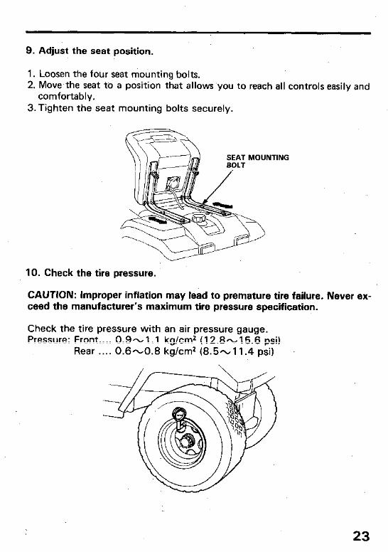
9. Adjust the seat position.
1. Loosen the four seat mounting bolts. 2. Move,the seat to a position that allows you to reach all controls easily and
comfortably. 3.Tighten the seat mounting bolts securely.
10. Check the tire pressure.
CAUTION: Improper inflation may lead to premature tire failure. Never ex- ceed the manufacturer’s maximum tire pressure specification.
Check the tire pressure with an air pressure gauge. Pressure: Front.. . . 0.9-1.1 kg/cm2 (12.8-15.6 psi)
Rear . . . . 0.6-0.8 kg/cm2 (8.5-l 1.4 psi)
23
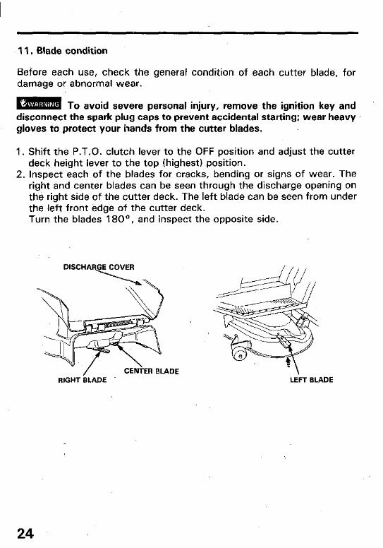
11. Blade condition
Before each use, check the general condition of each cutter blade, for damage or abnormal wear.
m To avoid severe personal injury, remove the ignition key and disconnect the spark plug caps to prevent accidental starting; wear heavy gloves to protect your hands from the cutter blades.
1. Shift the P.T.O. clutch lever to the OFF position and adjust the cutter deck height lever to the top (highest) position.
2. Inspect each of the blades for cracks, bending or signs of wear. The right and center blades can be seen through the discharge opening on the right side of the cutter deck. The left blade can be seen from under the left front edge of the cutter deck. Turn the blades 1 80°, and inspect the opposite side.
RIGHT BLADE LEFT BLADE
24
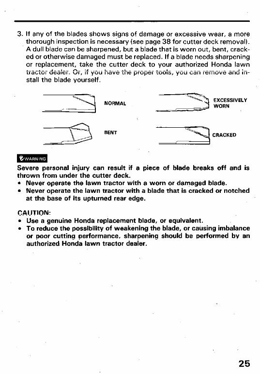
3. If any of the blades shows signs of damage or excessive wear, a more thorough inspection is necessary (see page 38 for cutter deck removal). A dull blade can be sharpened, but a blade that is worn out, bent, crack- ed or otherwise damaged must be replaced. If a blade needs sharpening or replacement, take the cutter deck to your authorized Honda lawn tractor dealer. Or, if you have the proper tools, you can remove and in- stall the blade yourself.
BENT -s
EXCESSIVELY WORN
CRACKED
Severe personal injury can result if a piece of blade breaks off and is thrown from under the cutter deck. l Never operate the lawn tractor with a worn or damaged blade. l Never operate the lawn tractor with a blade that is cracked or notched
at the base of its upturned rear edge.
CAUTION: l Use a genuine Honda replacement blade, or equivalent. l To reduce the possibility of weakening the blade, or catising imbalance
or poor cutting performance, sharpening should be performed by an authorized Honda lawn tractor dealer.
25
5. OPERATION
Starting the engine
m, Exhaust contains poisonous carbon monoxide gas that may cause loss of consciousness and lead to death. Never run the engine in an enclosed area. Be sure to provide adequate ventilation.
1. Sit on the seat and check that the transmission is in neutral and the P.T.0 lever is in the OFF (Disengaged) position.
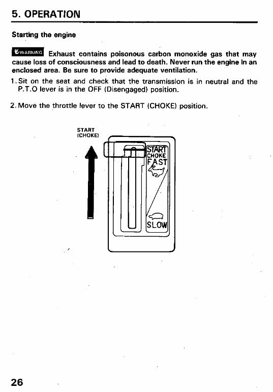
2. Move the throttle lever to the START (CHOKE) position.
START (CHOKE) .
26
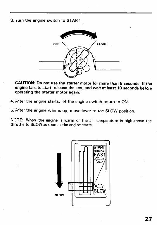
3.Turn the engine switch to START.
CAUTION: Do not use the starter motor for more than 5 seconds. If the engine fails to start, release the key, and wait at least 10 seconds before operating the starter motor again.
4. After the engine starts, let the engine switch return to ON. ,
5. After the engine warms up, move lever to the SLOW position.
NOTE: When the engine is warm or the air temperature is high,move the throttle to SLOW as soon as the engine starts.
1 c c
SLOW
27
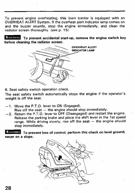
To prevent engine overheating, this lawn tractor is equipped with an OVERHEAT ALERT System. If the overheat- alert indicator la’mp comes on and the buzzer sounds, stop the engine immediately, and clean the radiator screen thoroughly. (see p. 151
m To prevent accidental start-up, remove the engine switch key before cleaning the radiator screen.
’ ALERT LAMP
6. Seat safety switch operation check.
The seat safety switch automatically stops the engine if the operator’s weight is off the seat.
- 1. Move the P.T.O. lever to ON (Engaged). Rise off the seat - the engine should stop immediately.
-2. Return the P.T.O. lever to OFF (Disengaged) and restart the engine. Release the parking brake and place the shift lever in the 1st speed range. While driving slowly, rise off the seat - the engine should stop immediately.
mm! To prevent loss of control, perform thig check on level ground, never on a slope.
28
Mowing
rwm Before operating this lawn tractor you should read and under- stand the Lawn Tractor Safety section on pages 5-7.
CAUTION: l In tall grass, first mow with the cutter deck fully raised (4.0 in); this will
expose any hidden obstacles. When you are sure the area is completely cleared, re-mow at the desired height.
l If the lawn tractor accidentally gets caught by some object, hole or curb, do not try to ride over the obstruction or turn the steering to free the mower, the steering mechanism or cutter deck may be damaged.
NOTE: For best results, wait until the lawn is dry before mowing.
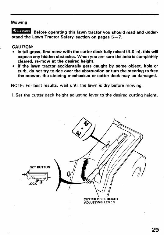
1. Set the cutter deck height adjusting lever to the desired cutting height.
SET BUTTON
CUTTER DECK HEIGHT ADJUSTING LEVER
29

2. Move the throttle lever to the FAST position.
CAUTION: When mowing ovei-rbugh ground or on hillsides, select the gear that will give a safe ground speed when the engine is operating at full throttle.
NOTE: The tractor can be operated qt intermediate throttle settings if desired, but always maintain suffi- cient engine speed for good pulling power arid efficient blade operation. Use: the shift lever to select the desired driving speed range.
THROTTLE LEVER
/ Y \ x
.
/
I / I
3. Move the P.T,.O. lever to the ON (Engaged) position.
OFF (Disengaged)
4. Move the shift lever to select the desired gear position. The clutch will engage automatically in about one second.
30
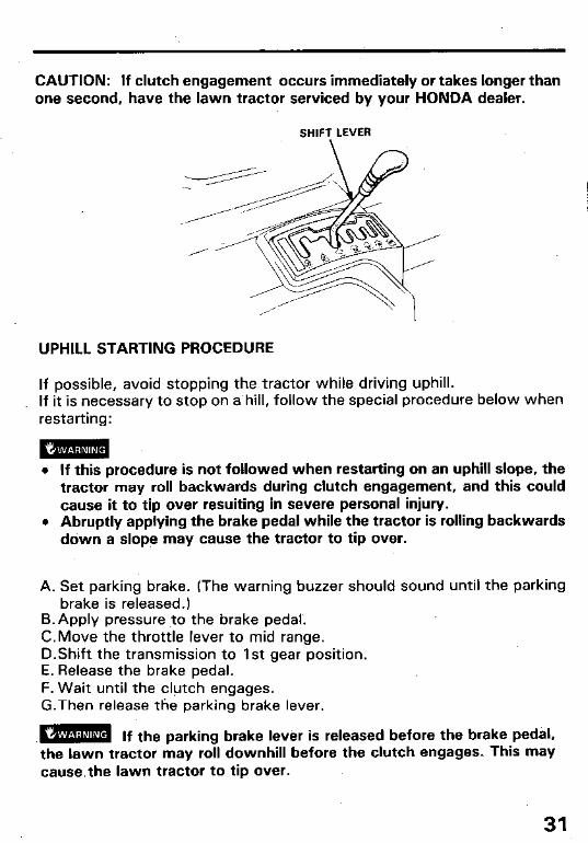
CAUTION: If clutch engagement occurs immediately or takes longer than one second, have the lawn tractor serviced by your HONDA dealer.
SHIFT LEVER
UPHILL STARTING PROCEDURE
If possible, avoid stopping the tractor while driving uphill. If it is necessary to stop on a.hill, follow the special procedure below when restarting:
m!m l If this procedure is not followed when restarting on an uphill slope, the
tractor may roll backwards during clutch engagement, and this could cause it to tip over resuiting in severe personal injury.
l Abruptly applying the brake pedal while the tractor is rolling backwards down a slope may cause the tractor to tip over.
A. Set parking brake. (The warning buzzer should sound until the parking brake is released.)
B.Apply pressure to the brake pedal.. C.Move the throttle lever to mid range. D.Shift the transmission to 1st gear position. E. Release the brake pedal. F. Wait until the clutch engages. G.Then release the parking brake lever.
w If the parking brake lever is released before the brake pedal, the lawn tractor may roil downhill before the clutch engages. This may cause.the lawn tractor to tip over.
31
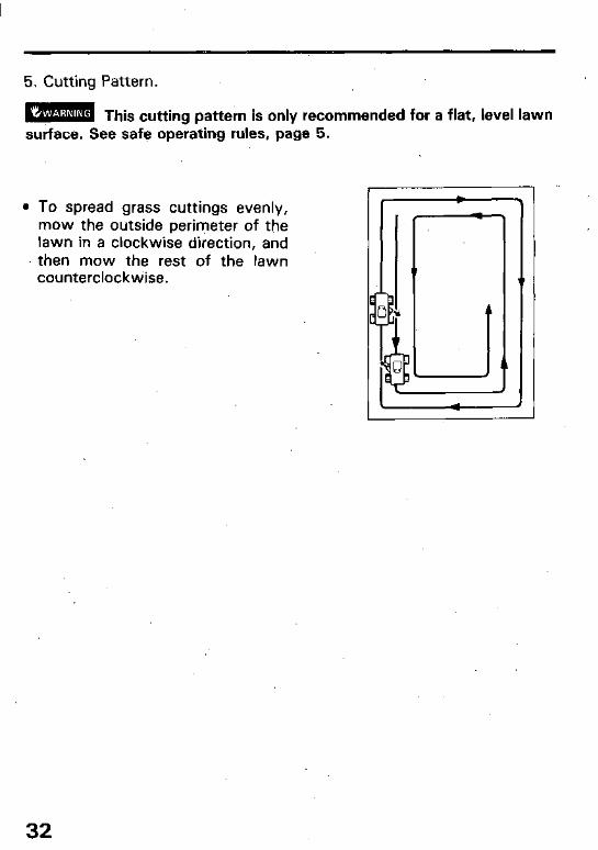
5. Cutting Pattern.
mm This cutting pattern is only recommended for a flat, level lawn surface. See safe ope%ing rules, pige 5.
l To spread grass cuttings evenly, mow the outside perimeter of the lawn in a clockwise direction, and then mow the rest of the lawn counterclockwise.
32
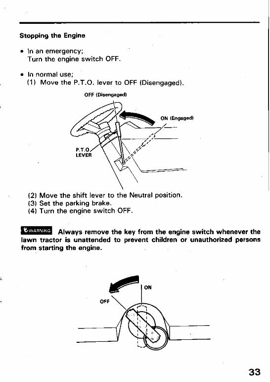
Stopping the Engine
l In an emergency;. Turn the engine switch OFF.
l In normal use; (1) Move the P.T.O. lever to OFF (Disengaged).
OFF (Disengaged)
(2) Move the shift lever to the Neutral position. (3) Set the parking brake. (4) Turn the engine switch OFF.
w Always remove the key from the engine switch whenever the lawn tractor is unattended to prevent children-or unauthorized persons from starting the engine.
I ON
33
High altitude operation
At high altitude, the standard carburetor air-fuel mixture will be excessively rich. Performance will decrease, and fuel consumption will increase.
High altitude performance can be improved by.installing a smaller diameter main fuel jet in the carburetor and ‘readjusting the pilot screw. If you always operate the Lawn Tractor at altitudes higher than 6,000 feet above sea level, ask your authorized Honda Lawn Tractor dealer to perform these carburetor modifications.
Even with suitable carburetor jetting, engine horsepower will decrease ap- proximately 3.5% for each 1,000 feet increase in altitude. The affect of altitude on horsepower will be greater than this if no carburetor modification is made.
CAUTION: Operation of the lawn tractor at an altitude lower than the car- buretor is jetted for may result in reduced performance, overheating, and serious engine damage caused by an excessively lean air/fuel mixture. . .
34
6. TRANSPORTING/STORAGE
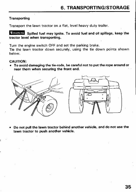
Transporting
Transport the lawn tractor on a flat, level heavy duty trailer.
iam Spilled fuel may ignite. To avoid fuel and oil spillage, keep the tractor level when transporting.
Turn the engine switch OFF and set the parking brake. Tie the lawn tractor down securely, using the tie down points shown below.
CAUTION: l To avoid damaging the tie-rods, be careful not to put the rope around or
near them when securing the front end.
l Do not pull the lawn tractor behind another vehicle, and do not use the lawn tractor to push another vehicle.
.35

Preparation for storage
The following steps should be taken to protect the tractor whenever it will be stored for longer than 30 days.
1. Drain all gasoline from the fuel tank into a suitable gasoline container.
EMa Do not drain the fuel tank when the exhaust system is hot.
Disconnect, the spark plug caps, and turn the engine switch to the ON position to activate the fuel pump.
Loosen the carburetor drain screw, and drain the fuel into a suitable gasoline container.
After draining, turn the engine stiitch OFF and tighten the drain screw securely.
Emm Gasoline is extremely flammable and explosive under certain conditions. Do not smoke or allow flames or sparks in the area.
36
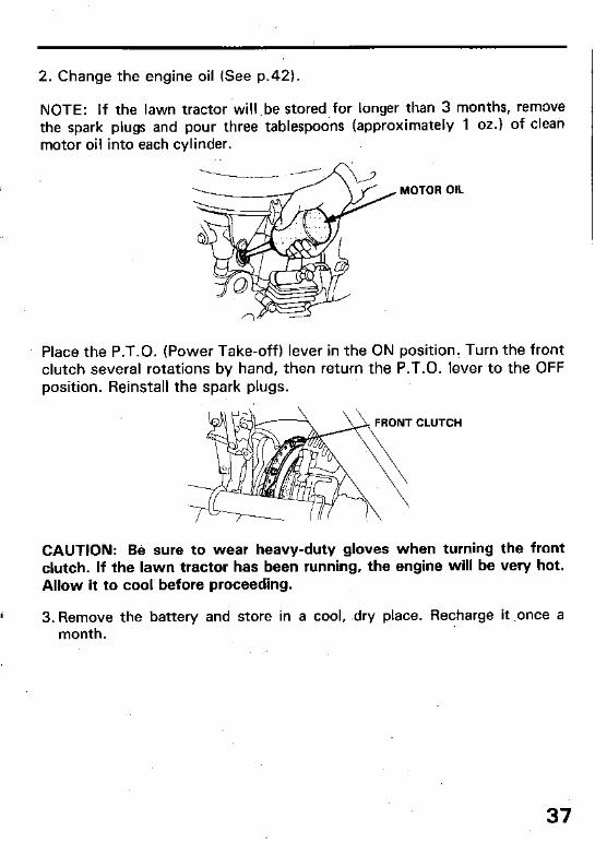
2. Change the engine oil (See p.42).
NOTE: If the lawn tractor will .be stored for longer than 3 months, remove the spark plugs and pour three tablespoons (approximately 1 oz.) of cleati motor oil into each cylinder.
-------- - MOTOR OIL
Place the P.T.O. (Power Take-off) lever in the ON position. Turn the front clutch several rotations by hand, then return the P.T.O. lever to the OFF position. Reinstall the spark plugs.
RONT CLUTCH
CAUTION: Be sure to wear heavy-duty gloves when turning the front clutch. If the lawn tractor has been running, the engine will be very hot. Allow it to cool before proceeding.
, 3. Remove the battery and store in a cool, .dry place. Recharge it .once a month.
37
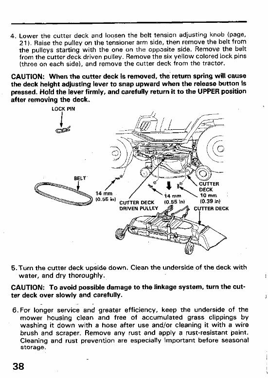
4. Lower the cutter deck and loosen the belt tension adjusting knob (page, 21). Raise the pulley on the tensioner arm side, then remove the belt from the pulleys starting with the one on the opposite side. Remove the belt from the cutter deck driven pulley. Remove the six yellow colored lock pins (three on each side), and remove the cutter deck from the tractor.
CAUTION: When the cutter deck is removed, the return spring will cause the deck height adjusting lever to snap upward when the release button is pressed. Hold the lever firmly, and carefully return it to the UPPER position after removing the deck.
LOCK PIN
BELT
%
14r;lm, (0.55 in)
CUTTER DECK (0.55 in)
-- \lOmm 1 (0.39 in)
5. Turn the cutter deck upside down. Clean the underside of the deck with water, and dry thoroughly.
CAUTION: To avoid possible damage to the linkage system, turn the cut- ter deck over slowly and carefully.
6. For longer service and greater efficiency, keep the underside of the mower housing clean and free of accumulated grass clippings by washing it down with a hose after use and/or cleaning it with a wire brush and scraper. Remove any rust and apply a rust-resistant paint. Cleaning and rust prevention are especially important before seasonal storage.
38
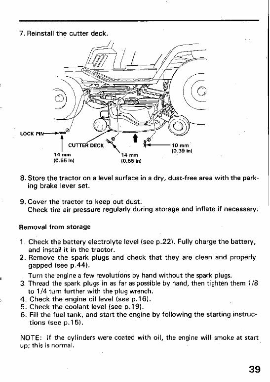
7. Reinstall the cutter deck.
LOCK .,-e.J @ t CUTTER DECK
14 mm 14 mm (0.39 in)
(0.55 in) (0.55 in)
8. Store the tractor on a level surface in a dry, dust-free area with the park- ing brake lever set.
9. Cover the tractor to keep out dust. Check tire air pressure regularly during storage and inflate if necessary:
Removal from storage
1. Check the battery electrolyte level (see p.22). Fully charge the battery, and install it in the tractor.
2. Remove the spark plugs and check that they are clean and properly gapped (see p.44).
i Turn the engine a few revolutions by hand without the spark plugs. 3. Thread the spark plugs in as far as possible by.hand, then tighten them l/8
to l/4 turn further with the plug wrench. 4. Check the engine oil level (see p.16). 5. Check the coolant level (see p.19). 6. Fill the fuel tank, and start the engine by following the starting instruc-
tions (see p. 15).
NOTE: If the cylinders were coated with oil, the engine will smoke at start up; this is normal.
39
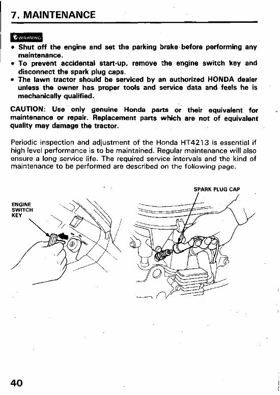
7. MAINTENANCE
l Shut off the engine and set the parking brake’before performing any maintenance.
l To prevent accidental start-up, remove the engine switch key and disconnect the spark plug caps.
l The lawn tractor sh,ould be serviced by an authorized HONDA dealer unless the owner has proper tools and. service data and feels he is mechanically qualified.
CAUTION: Use only genuine Honda parts or their equivalent for maintenance or repair. Replacement parts which are not of equivalent quality may damage the tractor.
Periodic inspection and adjustment of the Honda HT4213 is essential if high level performance is to be maintained..Regular maintenance will also ensure a long service life. The required service intervals and the kind of maintenance to be performed are described on the following page.
SPARK PLUG CAP
ENGINE
40
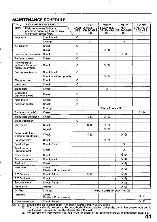
MAINTENANCE SCHEDULE
Adjust 0 (2) Brake and clutch (fastener tightness)
Check 0 (2) 0 (2)
1 Parkina brake
Spark plugs
Spark arrester (optional part)
Drive clutch
Check
Check-Clean
Clean
Check
0 (2) 0
0
0 (2)
1 Transmission oil Check level I I I I 012) I I Fuel tank
Fuel filter
P.T.0 cable
Clean
Check (Replace if necessary)
Check-Adjust
0 (2)
0 (2)
0 (2) 0 (21 1 P.T.0 clutch I I
Throttle cable Check-Adjust
Front axle Grease
1 0 (2) 1
I 0 (21 I
Oil filter Change Every 2 years or 300 HRS (2)
Fuel line Check IR~nlare if ~LC*~EX~ . . ._r .--- ..------. !I
0 (2)
Valve clearance Check-Adjust 0 (2) NOTE: (1) Service the air cleaner more frequently when used in dusty areas.
(2) These items should be serviced by an authorized Honda dealer, unless the owner has proper tools and is mechanically proficient. See the Honda Shop Manual.
(3) For professional commercial use, log hours of operation to determine proper maintenance intervals.
41
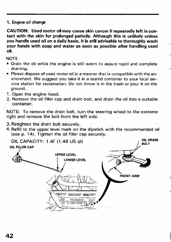
1. Engine oil change
CAUTION: Used motor oil may cause skin cancer if repeatedly left in con- tact with the skin for prolonged periods. Although this is unlikely unless you ‘handle used oil on a daily basis, it is still advisable to thoroughly wash your hands with soap and water as soon as possible after handling used oil.
NOTE: l Drain the oil while the engine .i.s still warm to assure rapid and complete
draining. l Please dispose of used motor oil in a manner that i& compatible.with the en-
vironment. We suggest you take it in a sealed container to your local ser- vice station for reclamation. Do not throw it in the trash or pour it on the ground.
1. Open the engine hood. 2. Remove the oil filler cap and drain bolt, and drain the oil into a suitable
container.
NOTE: To remove the drain bolt, turn the steering wheel to the extreme right and remove the bolt from the left side.
3. Retighten the drain bolt securely. 4. Refill to the upper level mark on the dipstick with the recommended oil
(see p. 14). Tighten the oil filler cap securely.
OIL CAPACITY: 1.49 (1.48 US qt)
OIL FILLER CAP
UPPER LEVEL
I LOWER LEVEL
42
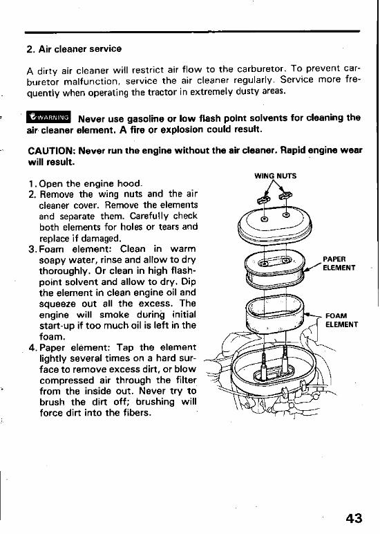
2. Air cleaner service
A dirty air cleaner will restrict air flow to the carburetor. To prevent car- buretor malfunction, service the air cleaner regularly. Service more fre- quently when operating the tractor in extremely dusty areas.
m Never use gasoline or low flash point solvents for cleaning the air, cleaner element. A fire or explosion could result.
CAUTION: Never run the engine without the air cleaner. Rapid engine wear will result.
1. Open the engine hood. 2. Remove the wing nuts and the air
cleaner cover. Remove the elements and separate them. Carefully check both elements for holes or tears and replace if damaged.
WING NUTS
3. Foam element: Clean in warm soapy water, rinse and allow to dry thoroughly. Or clean in high flash- point solvent and allow to dry. Dip the element in clean engine oil and squeeze out all the excess. The engine will smoke during initial start-up if too much oil is left in the foam.
4. Paper element: Tap the element lightly several times on a hard sur- face to remove excess dirt, or blow compressed air through the filter from the inside out. Never try to brush the dirt off; brushing will force dirt into the fibers.
43
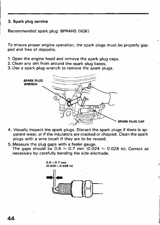
3. Spark plug service
Recommended spark plug: BPR4HS (NGK)
To ensure proper engine operation, the spark plugs must be properly gap- ped and free of deposits.
1. Open the engine hood and remove the spark plug caps. 2. Clean any dirt from around’the spark plug bases. 3. Use a spark plug wrench to remove the spark plugs.
SPARK PLUG WRENCH
SPARK PLUG CAP
4. Visually inspect the spark plugs. Discard the spark plugs if there is ap- parent wear, or if the insulators are cracked or chipped. Clean the spark plugs with a wire brush if they are to be reused.
5. Measure the plug gaps with a feeler gauge. The gaps should be 0.6 - 0.7 mm (0.024 * 0.028 in). Correct as necessary by carefully bending the side electrode.
0.6-0.7 mm 10.024-0.028 in)
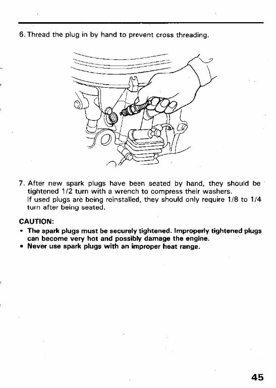
6.Thread the plug in by hand to prevent cross threading.
7. After new spark plugs have been seated by hand, they should be tightened l/2 turn with a wrench to compress their washers. If used plugs ark being reinstalled, they should only require l/8 to l/4 turn after being seated.
CAUTION:
l The spark plugs must be securely tightened. Improperly tightened plugs can become very hot and possibly damage the engine.
l Never use spark plugs with an improper heat range.
45
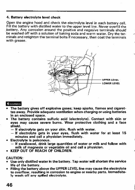
4. Battery electrolyte level check
Open the engine hood and check the electrolyte level in each battery cell. Fill the battery with distilled water to the upper level li.ne. Never overfill the battery. Any corrosion around the positive and negasive terminals should be washed off with a solution of baking soda and warm water. Dry the ter- minals and retighten the terminal bolts if necessary, then coat the terminals with grease.
UPPER LEVEL
LOWER LEVEL
l The battery gives off explosive gases; keep sparks, flames and cigaret- tes away. Provide adequate ventilation when charging or using batteries in an enclosed space.
l The battery contains sulfuric acid (electrolyte): Contact with skin or eyes may cause severe burns. Wear protective clothing and a face shield. - If electrolyte gets on your skin, flush with water. - If electrolyte gets in your eyes, flush with water for’ at least 15
minutes and call a physician immediately. l Electrolyte is poisonous.
- If swallowed, drink large quantities of water or milk and follow with milk of magnesia or vegetable oil and call a physician.
. KEEP OUT OF REACH OF CHILDREN.
CAUTION:. l Use only distilled water in the battery. Tap water will shorten the service
life of the battery. l Filling the battery above the UPPER LEVEL line may cause the electrolyte
to overflow, resulting in corrosion to engine or nearby parts. Immediate- ly wash off any spilled electrolyte.
46
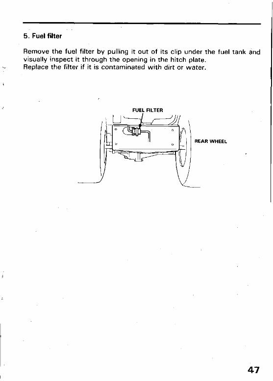
5. Fuel filter
Remove the fuel filter by pulling it out of its clip under the fuel tank and visually inspect it through the opening in the hitch plate. Replace the filter if it is contaminated with dirt or water.
i
r‘
FUEL FILTER
REAR WHEEL
,
47
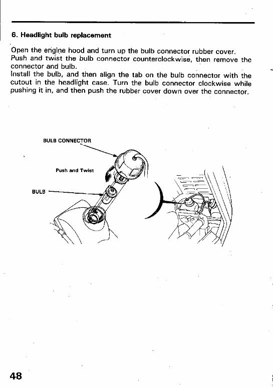
6. Headlight bulb replacement
‘Open the et-@in-e hood and turn up the bulb connector rubber cover. Push and twist the bulb connector counterclockwise, then remove the connector and bulb. Install the bulb, and then align the tab on the bulb connector with the cutout in the headlight case. Turn the bulb connector clockwise while pushing it in, and then push the rubber cover down over the connector.
BULB CONNECTOR
Push and Twist
BULB
48

7. Wheel removal
l Do riot attempt to remove a wheel unless the lawn tractor is on firm and - level ground.
l Do not attempt to remove or replace a tire unless you have the equipment and knowledge to do so properly.
Block wheels securely. 1. Remove the center cap and cotter pin. 2. Remove the wheel hub nut with .a 19 mm socket. 3. Raise the wheel off the floor using a jack and remove the wheel. 4. Apply a thin coat of grease to the wheel shaft splines before installing
the rear wheel. Install the washer with its “OUTSIDE” mark facing out. Tighten the hub nut first to 5.5 kg-m (40 ft-lb) then continue tightening it until one of the cutouts in the nut aligns with the hole in the shaft. Install a new cotter pin on the shaft and bend it as shown.
[Jack points1 Front
CENTER CAP
WHEEL HUB NUT FLAT WASHER

8. Cutter deck drive belt replacement
mwm Never attempt to change drive belts while the engine is running. Remove the engine key from the ignition and disconnect the spark plug caps to prevent accidental start up.
~
CAUTION:
l Wear heavy gloves to protect your hands when replacing drive belts or when working with cutter blades.
l If the tractor has been running, the engine, muffler and radiator will be very hot. Allow them to cool before proceeding.
1. Lower the cutter deck. 2. Loosen the belt tension adjusting knob. Remove the belt stopper B
located near the tensioner pulley and raise the pulley on the tensioner arm side. Remove the belt from the pulleys starting with the one on the opposite side.
3. Remove the belt from the cxitter deck driven pulley. 4. Open the engine hood, and remove the belt stopper by removing the 10
mm flange nut.’ 5. Release the clips and open the upper radiator shroud. 6. Remove the belt through the top by first lifting the belt up,, and then
sliding it sideways toward the radiator as shown in Fig. (A).
7. Installation sequence is essentially the reverse order of r&moval. See Page 21 for belt tension adjustment.
CAUTION: l When reinstalling the belt stopper, check that the clearance between
the belt stopper and pulley is 3-6 mm (0.1-0.2 in.), then tighten the 10 mm flange nut securely.
l After installing the belt and adjusting the belt tension, start the engine and shift the P.T.O. lever into ON and OFF to tie sure that it operates properly.
50
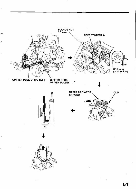
FLANGE NUT 10mm \
CUTTER DE& DRIVE BELT CUTTER DECK DRIVEN PULLEY ’
51

9. Blade belt replacement
1. Lower the cutter deck, remove the six yellow colored lock pins (see p.38) and remove the cutter deck.
2. Remove the bolts and nuts and remove the pulley covers. 3. Pull the belt section between pulley A and pulley B toward you, then
remove the belt from pulley A while releasing it slowly.
CAUTION: If the belt is not released slowly, the idle pulley will move sud- denly and could injure your hand.
4, Remove the belt from the other pulleys, and replace. the belt.
PULLiY B I -7 --‘I’
NOTE: When installing the belt covers, the edge of the left cover overlaps the right cover under the belt guide, as shown.
5
LEFi BELT
52 COVER
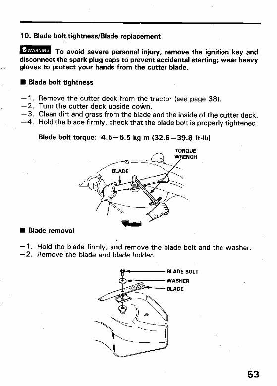
10. Blade bolt. tightness/Blade replacement
m To avoid severe personal iniury, remove the ignition key and disconnect the spark plug cabs to prevint accidental starting; wear heavy gloves to protect your hands from the cutter blade.
n Blade bolt tightness
- 1. Remove the cutter deck from the tractor (see page 38). -2. Turn the cutter deck upside dotin. -3. Clean dirt and grass from the blade and the inside of the cutter deck. -4. Hold the blade firmly, check that the blade bolt is properly tightened.
Blade bolt torque: 4.5-5.5 kg-m (32.6-39.8 ft-lb)
TORQUE
W Blade removal
- 1. Hold the blade firmly, and remove the blade bolt and the washer. -2. Remove the blade and blade holder.
P - BLADE BOLT
53
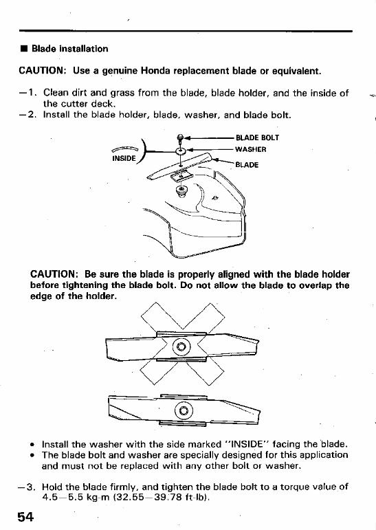
W Blade installation
CAUTION: Use a genuine Honda replacement blade or equivalent.
- 1. Clean dirt and grass from the blade, blade holder, and the inside of the cutter deck.
-2. Install the blade holder, blade, washer, and blade bolt.
CAUTION: Be sure the blade is properly aligned with the blade holder before tightening the blade bolt. Do not allow the blade to overlap the edge of the holder.
L--- , l Install the washer with the side marked “INSIDE” facing the ‘blade. l The blade bolt and washer are specially designed for this application
and must not be replaced with any other bolt or washer.
-3. Hold the blade firmly, and tighten the blade bolt to a torque value of 4.5-5.5 kg-m (32.55-39;78 ft-lb).
54

13. Spark arrester maintenance (optional part)
You can purchase an opti,onal, U.S.D.A. qualified spark arrester for this product from your authorized Honda Power Equipment dealer. Spark ar- resters are required in some areas; check local laws and regulations before operating this Honda product.
mzm The muffler becomes very hot during operation and remains hot for a while after the engine &tops: Be carefucnot to touch the muffler while it is hot. Allow it to cool before proceeding.
CAUTION: The spark arrester must be serviced every 100 hours to main- tain its efficiency; 1. Remove the four 6 mm bolts and remove the muffler protector.
2. Remove the two 5 mm screws from the exhaust pipe tip. Remove the exhaust pipe tip and spark arrester (be careful not to damage the spark arrester screen).
3. Use a wire brush to remove carbon deposits from the spark arrester screen. NOTE: Inspect the spark arrester screen for holes or tears. Replace it if it is damaged.
-55
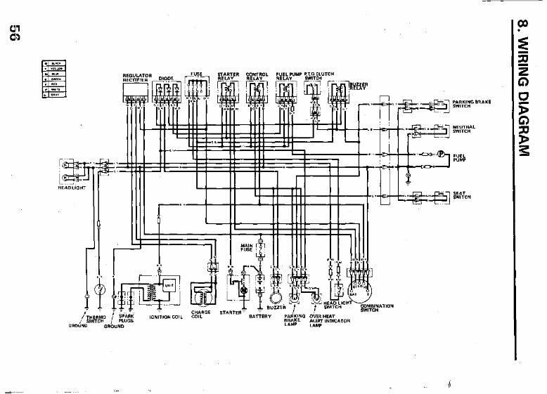
8. W
IRIN
G
DIA
GR
AM
-a f
56

9. TROUBLESHOOTING
Engine fails to start; 1. No fuel. w Add fuel. 2. Shift lever in gear. w Position shift .lever in NEUTRAL. 3. P.T.O. lever engaged.- Position blade (P.T.O.) lever in
a- DISENGAGE. 4. Spark plug faulty or.- Regap plug or replace (see p. 44).
improperly gapped. 5. Spark plug wire loose- Check spark plug wire.
or disconnected. 6. Fuel not reaching w See your authorized HONDA lawn
carburetor. tractor dealer. 7. Discharged battery or - Charge battery or retighten terminal.
loose terminal. (see p. 46).
Engine loses power; 1. Dirty air cleaner elements.- Clean or replace elements
(see p. 43). 2. Spark plug faulty or - Regap plug or replace.
improperly gapped. 3. Engine overloaded. w Shift to lower speed.
Engine overheats; 1. Radiator screen plugged. -’ Clean radiator screen (see p. 15).
2. Engine overloaded. m Shift to lower speed. 3. Low engine oil level.- Fill with recommended oil
(see p. 16). 4. Spark plug improperly.- Regap plug or replace.
gapped
5. Lack of radiator coolant. - Fill with recommended coolant (see p. 19).
57.
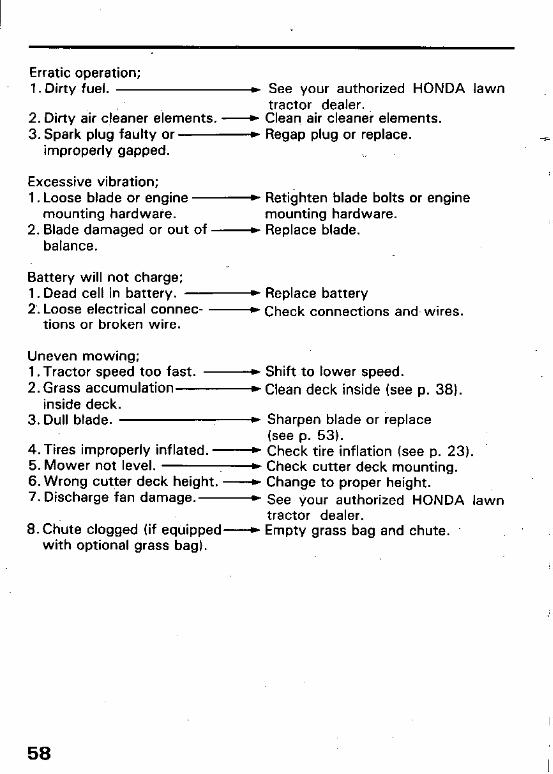
Erratic operation; 1. Dirty fuel. b See your authorized HONDA lawn
2. Dirty air cleaner elements. B tractor dealer. Clean, air cleaner elements.
3. Spark plug faulty or- Regap plug or replace. -5 improperly gapped. ,.
Excessive vibration; 1. Loose blade or engine - Retighten blade bolts or engine
mounting hardware. mounting hardware. 2. Blade damaged or out of - Replace blade.
balance.
Battery will not charge; 1. Dead cell in battery. - Replace battery 2; Loose electrical connec- - Check connections and. wires.
tions or broken wire.
Uneven mowing; 1. Tractor speed too fast. - Shift to lower speed.
2. Grass accumulation- Clean deck inside (see p. 38). inside deck.
3. Dull blade. D Sharpen blade or replace (see p. 53).
4. Tires improperly inflated. - Check tire inflation (see p. 23). 5. Mower not level. * Check cutter deck mounting. 6. Wrong cutter deck height. - Change to proper height. 7. Discharge fan damage. - See your authorized HONDA lawn
tractor dealer. 8. Chute clogged (if equipped--+ Empty grass bag and chute.
with optional grass bag).
58

Clogged cutter deck discharge chute. 1. Wrong blade. b.Use genuine Honda blade or equiv-
alent.
2. Deck too low: ) Raise deck and adjust deck height r-- properly.
3. Engine overloaded.- Operate at full throttle. Use lower speed range. Set cutter deck higher than desired height for first pass, then cut to desired height on second pass.
4. Grass bags full * Empty grass bags. (Optional part).
Blades do not rotate or stop. 1. Blade drive belt worn or - Replace with-new belt (see p. 51).
broken. 2. P.T.O. lever cable cut or - See your authorized HONDA lawn
out of adjustment. tractor dealer. 3. Faulty P.T.O. clutch assy- See your authorized HONDA lawn
or worn disk. tractor dealer.
Tractor does not move, or clutch does not engage properly when the transmission is shifted into gear. 1. Faulty clutch assy.- See your authorized HONDA lawn
tractor dealer. 2. Transmission does not - See your authorized HONDA lawn
.shift gear. . tractor dealer. 3. Abnormal clutch engage- - See your authorized HONDA lawn
ment. tractor dealer.
59
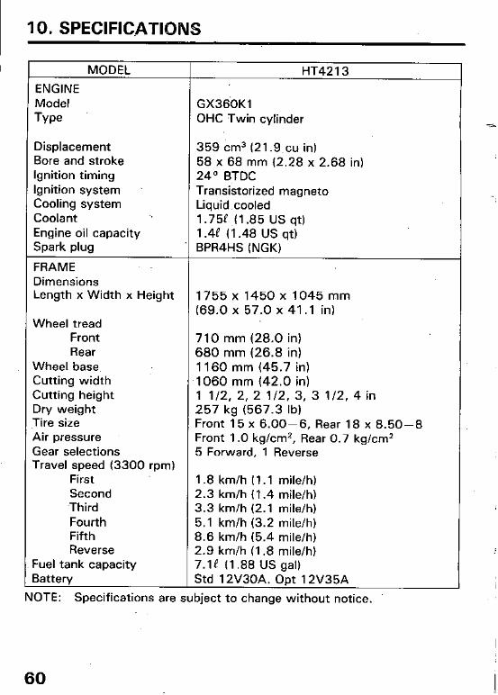
IO. SPECIFICATIONS
I MODEL HT42 13
ENGINE Model GX36OKl
Type OHC Twin cylinder
Displacement 359 cm3 (21.9,cu in) Bore and stroke 58 x 68 mm (2.28 x 2.68 in) Ignition timing 24’ BTDC Ignition system Transistorized magneto Cooling system Liquid.cooled Coolant 1.752 ,(1.85 US qt) Engine oil capacity 1.4P (1.48 US qt) Spark plug BPR4HS (NGK)
FRAME Dimensions Length x Width x Height 1755 x 1450 x 1045 mm
(69.0 x 57.0 x 41 .l in) Wheel tread
Front 710 mm (28.0 in) Rear 680 mm (26.8 in)
Wheel base ’ 1160 mm (45.7 in) Cutting width 1060 mm (42.0 in) Cutting height 1 l/2, 2, 2 l/2, 3, 3 l/2, 4 in Dry weight 257 kg (567.3 lb) Tire size Front 15 x 6.00-6, Rear 18 x 8.50-8 Air pressure Front 1 .O kg/cm2, Rear 0.7 kg/cm2 Gear selections 5 Forward, 1 Reverse Travel speed (3300 rpm)
First 1.8 km/h (1.1 mile/h) Second 2.3 km/h (1.4 mile/h) Third 3.3 km/h (2.1 mile/h) Fourth 5.1 km/h (3.2 mile/h) Fifth 8.6 km/h (5.4 mile/h) Reverse 2.9 km/h (1.8 mile/h)
Fuel tank capacity 7.18 (1.88 US gal) Battery Std 12V30A. Opt 12V35A
NOTE: Specifications are subject to change without notice.
60
Owner Satisfaction
11. WARRANTY SERVICE
Your satisfaction and goodwill are important to your dealer and to us. All Honda warranty details are explained in the Distributor’s Limited Warranty. Normally, any problems concerning the product will be handled by your dealer’s service,department. If you have a warranty problem that has not been handled to your satisfaction, we suggest you take the following action:
l Discuss your problem with a member of dealership management. Often complaints can be quickly resolved at that level. If the problem has already been reviewed with the Service Manager, contact the owner of the dealership or the General Manager.
l If your problem still has not been resolved to your satisfaction, contact the Power Equipment Customer Relations Department of American Honda Motor Co., Inc.
American Honda Motor Co., Inc. Power Equipment Customer Relations Department P.O. Box 50 Gardena, California 90247-0805 Telephone: (2 13) 604-2400
We will need the folfowing information in order to assist you:
- Your name, address, and telephone number - Product model and serial number - Date of purchase - Dealer name and address - Nature of the problem
After reviewing all the facts involved, you will be advised of what action can be taken. Please bear in mind that your problem will likely be resolved at the dealership, using the dealer’s facilities, equipment, and personnel, so it is very important that your initial contact be with the dealer.
Your purchase of a Honda product is greatly appreciated by both your dealer and American Honda Motor Co., Inc. We want to assist you in every way possible to assure your complete satisfaction with your purchase.
61

Current customer service contact information: United States, Puerto Rico, and U.S. Virgin Islands: Honda Power Equipment dealership personnel are trained professionals. They should be able to answer any question you may have. If you encounter a problem that your dealer does not solve to your satisfaction, please discuss it with the dealership's management. The Service Manager or General Manager can help. Almost all problems are solved in this way.
If you are dissatisfied with the decision made by the dealership's management, contact the Honda Power Equipment Customer Relations Office. You can write:
American Honda Motor Co., Inc. Power Equipment Division Customer Relations Office 4900 Marconi Drive Alpharetta, GA 30005-8847
Or telephone: (770) 497-6400 M-F, 8:30 am - 7:00 pm EST
When you write or call, please provide the following information:
• Model and serial numbers
• Name of the dealer who sold the Honda power equipment to you
• Name and address of the dealer who services your equipment
• Date of purchase
• Your name, address, and telephone number
• A detailed description of the problem

MEMO
62

MEMO
63

MEMO
64