Embed Size (px)
Citation preview

September 2012 Doc IEEE P802. 15-12-0512-01-004m
IEEE P802.15
Wireless Personal Area Networks
Project IEEE P802.15 Working Group for Wireless Personal Area Networks (WPANs)
Title TG4m Merged MAC Proposal
Date Submitted
[Sept 18 2012]
Source [See Contributors Page][]
Voice: [ +1 408 395 7207 ]Fax: [ ]E-mail: [ ]
Re: [If this is a proposed revision, cite the original document.]
[If this is a response to a Call for Contributions, cite the name and date of the Call for Contributions to which this document responds, as well as the relevant item number in the Call for Contributions.]
[Note: Contributions that are not responsive to this section of the template, and contributions which do not address the topic under which they are submitted, may be refused or consigned to the “General Contributions” area.]
Abstract [Description of document contents.]
Purpose [Description of what the author wants P802.15 to do with the information in the document.]
Notice This document has been prepared to assist the IEEE P802.15. It is offered as a basis for discussion and is not binding on the contributing individual(s) or organization(s). The material in this document is subject to change in form and content after further study. The contributor(s) reserve(s) the right to add, amend or withdraw material contained herein.
Release The contributor acknowledges and accepts that this contribution becomes the property of IEEE and may be made publicly available by P802.15.
TG4m Merged MAC Proposal Page 1

September 2012 Doc IEEE P802. 15-12-0512-01-004m
This proposal represents the combined efforts of a many contributors
Name Affiliation Name Affiliation
Chin-Sean Sum NICT Youngae Jeon ETRI
Ming-Tuo Zhou NICT Sangjae Lee ETRI
Zhou Lan NICT Sangsung Choi ETRI
Fumihide Kojima NICT Soo-Young Chang SYCA
Liru Lu NICT Kunal Shah Silver Spring Networks
Funada Ryuhei NICT Benjamin Rolfe BCA
Hiroshi Harada NICT
TG4m Merged MAC Proposal Page 2

September 2012 Doc IEEE P802. 15-12-0512-01-004m
ContentsIntroduction to this document....................................................................................................................5
3 Definitions, acronyms, and abbreviations...........................................................................................5
3.1 Definitions...................................................................................................................................5
3.2 Acronyms and abbreviations.......................................................................................................5
4 General description.............................................................................................................................6
4.2 Components of the IEEE 802.15.4 WPAN....................................................................................6
4.3 Network topologies.....................................................................................................................6
4.3.1 STAR network formation......................................................................................................6
4.3.2 Peer to peer network formation..........................................................................................6
4.5 Functional Overview....................................................................................................................7
4.5.1 Superframe structure...........................................................................................................7
4.5.2 Data Transfer Model............................................................................................................8
4.5.5 Power consumption considerations.....................................................................................8
4.5.7 Overview of TVWS operation...............................................................................................8
5 MAC Protocol.......................................................................................................................................9
5.1 MAC functional description.........................................................................................................9
5.1.1 Channel Access....................................................................................................................9
5.1.2 Starting and maintaining PANs..........................................................................................11
5.1.3 Association and disassociation...........................................................................................11
5.1.4 Synchronization.................................................................................................................11
5.1.5 Transaction handling..........................................................................................................11
5.1.6 Transmission, reception and acknowledgement................................................................11
5.1.7 GTS allocation and management.......................................................................................16
5.1.8 Ranging..............................................................................................................................16
5.1.14 Starting and maintaining TVWS Multichannel Cluster Tree PANs (TMCTP).......................18
5.1.15 TVWS Power saving (TVWSPS)...........................................................................................22
5.2 MAC frame formats...................................................................................................................23
5.2.2 Format of individual frame types.......................................................................................23
5.2.4 Information Elements........................................................................................................23
TG4m Merged MAC Proposal Page 3
September 2012 Doc IEEE P802. 15-12-0512-01-004m
5.3 MAC command frames..............................................................................................................34
5.3.4 Data request command.....................................................................................................35
5.3.14 DBS request command frame............................................................................................35
5.3.15 DBS response command frame..........................................................................................36
5.3.16 Neighbor discovery request command..............................................................................37
5.3.17 Neighbor discovery response command............................................................................37
5.3.18 Probe command.................................................................................................................37
5.5 TVWS access procedures...........................................................................................................38
5.5.1 Channel Timing Management (CTM).................................................................................39
5.5.2 Network Channel Control (NCC)........................................................................................39
6 MAC services.....................................................................................................................................40
6.2 MAC management service.........................................................................................................40
6.2.2 Association primitives........................................................................................................40
6.2.3 Disassociation primitives....................................................................................................40
6.2.4 Communications notification primitives............................................................................40
6.2.6 GTS management primitives..............................................................................................41
6.2.9 Primitives for specifying the receiver enable time.............................................................41
6.2.10 Primitives for channel scanning.........................................................................................41
6.2.12 Primitives for updating the superframe configuration.......................................................41
6.2.14 Primitives for requesting data from a coordinator............................................................41
6.2.17 Primitives for ranging calibration (for UWB PHYs).............................................................42
6.2.18 Primitives for Beacon Generation......................................................................................43
6.2.19 Primitives for TSCH............................................................................................................43
6.2.22 Operating parameter change primitives............................................................................43
6.2.23 TMCTP DBS allocation primitives.......................................................................................45
6.2.24 Primitives for neighbor discovery......................................................................................50
6.3 MAC data service.......................................................................................................................52
6.3.12 MCPS-Data.request............................................................................................................52
6.3.13 MCPS-DATA.confirm..........................................................................................................52
6.3.14 MCPS-DATA.indication.......................................................................................................52
6.4 MAC constants and PIB attributes.............................................................................................53
ANNEX Q Considerations for operation in TVWS......................................................................................55
TG4m Merged MAC Proposal Page 4
September 2012 Doc IEEE P802. 15-12-0512-01-004m
Q.1. Introduction...................................................................................................................................55
Q.2. Enabling access to TVWS channels................................................................................................55
Q.3. Considerations in non-beacon PANs..............................................................................................55
Q.4. Band sharing..................................................................................................................................55
Q.5. Other.............................................................................................................................................55
Introduction to this document This document contains details of the consolidated proposed MAC related changes to support operation of the TVWS PHY amendment for 802.15.4. The content represents the combined efforts of many contributors. This document is organized according to the structure of the base standard as published at the time of this writing, comprising 802.15.4-2011, 802.15.4e-2012, 802.15.4f-2012 and 802.15.4g-2012. Material proposed in ongoing amendments 802.15.4j and 802.15.4k is used in this document and repeated here as a convenience to the reader.
This is being prepared concurrently with the development of PHY layer proposals; many details of the PHY layer for TVWS operation are not yet known. Where specific PHY parameters or other PHY specific details are given, it is intended for illustrative purposes and expected to change. This is a work in progress that will be updated as the PHY proposal details become known.
3 Definitions, acronyms, and abbreviations
3.1 DefinitionsInsert the following definitions alphabetically into 3.1:
TVWS Multichannel Cluster Tree PAN (TMCTP): A PAN operating in a TVWS band employing a Super PAN coordinator to form a multi-channel cluster tree topology.
Super PAN Coordinator: The PAN coordinator of a TVWS Multichannel Cluster Tree PAN which was access to the TVWS geolocation database and provides synchronization services for the TVWS Multichannel Cluster Tree PAN.
TVWS Channel: Spectrum unit allocation as defined by the TV bands channel availability database.
3.2 Acronyms and abbreviationsInsert the following acronyms alphabetically into 3.2:
BOP Beacon Only PeriodDBS Dedicated Beacon Slot
TG4m Merged MAC Proposal Page 5

September 2012 Doc IEEE P802. 15-12-0512-01-004m
GDB Geolocation DataBaseSPC Super PAN coordinatorTMCTP TVWS Multichannel Cluster Tree PANTVWS TeleVision White Space
4 General description
4.2 Components of the IEEE 802.15.4 WPANInsert the following paragraph at the end of 4.2:
A TVWS Multichannel Cluster Tree PAN (TMCTP) includes at least one FFD, which operates as both the PAN coordinator and the super PAN coordinator (SPC). The SPC communicates with other PAN coordinator on their dedicated channels at the beacon only period (BOP), as described in 5.1.1.1.3.
4.3 Network topologies
4.3.1 STAR network formation
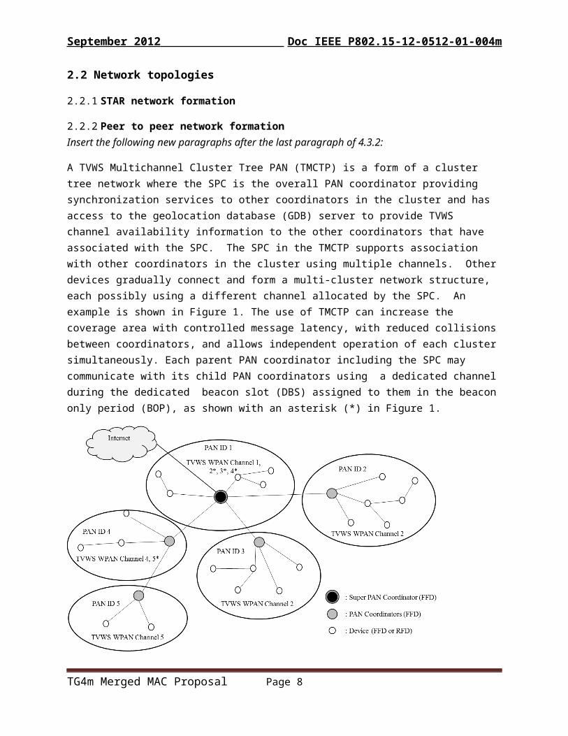
4.3.2 Peer to peer network formationInsert the following new paragraphs after the last paragraph of 4.3.2:
A TVWS Multichannel Cluster Tree PAN (TMCTP) is a form of a cluster tree network where the SPC is the overall PAN coordinator providing synchronization services to other coordinators in the cluster and has access to the geolocation database (GDB) server to provide TVWS channel availability information to the other coordinators that have associated with the SPC. The SPC in the TMCTP supports association with other coordinators in the cluster using multiple channels. Other devices gradually connect and form a multi-cluster network structure, each possibly using a different channel allocated by the SPC. An example is shown in Figure 1. The use of TMCTP can increase the coverage area with controlled message latency, with reduced collisions between coordinators, and allows independent operation of each cluster simultaneously. Each parent PAN coordinator including the SPC may communicate with its child PAN coordinators using a dedicated channel during the dedicated beacon slot (DBS) assigned to them in the beacon only period (BOP), as shown with an asterisk (*) in Figure 1.
TG4m Merged MAC Proposal Page 6

September 2012 Doc IEEE P802. 15-12-0512-01-004m
Figure 1: Example of TVWS multichannel cluster PAN
4.5 Functional Overview
4.5.12 Superframe structureInsert the following new subclause (4.5.1.5) after 4.5.1.4:
4.5.12.5 Superframe Usage for TVWS
4.5.12.5.1TVWS Multichannel Cluster Tree PAN (TMCTP) Superframe ExtensionThis standard allows the optional use of a superframe structure in a TVWS Multichannel Cluster Tree PAN (TMCTP) that is extended by the addition of a beacon only period (BOP) to the active portion of the superframe. The format of the TMCTP superframe is defined by the SPC. The TMCTP superframe is bounded by network beacons sent by the SPC. The active portion of the TMCTP superframe is composed of a beacon, a CAP, a CFP and a BOP. An example of a TMCTP superframe including the BOP is illustrated in Figure 2. The BOP is composed of one or more DBSs. A DBS is used to communicate beacons between the parent PAN coordinator and the child PAN coordinator. More information on the TMCTP superframe structure can be found in 5.1.1.1a.
TG4m Merged MAC Proposal Page 7
September 2012 Doc IEEE P802. 15-12-0512-01-004m
Figure 2: TMCTP superframe extension
4.5.12.5.2Generalized GTS usageIn a TVWS PAN allocated GTS may be configured for direct peer-to-peer communication. When a frame is transmitted in a GTS with a valid destination address, implicit addressing based on the GTS direction parameter is not used.
[more overview of GTS features support TVWS operation?]
4.5.13 Data Transfer ModelInsert new subclause at the end of 4.5.2:
4.5.13.4 Direct device-to-device data transferDirect device-to-device data transfer enables data transfer between two or more neighbor devices directly on a beacon-enabled PAN. Neighbor devices are peer devices associated with the same coordinator or PAN coordinator on a beacon-enabled PAN.
Direct device-to-device data transfer has four operation modes: (a) Probe-mode direct data transfer; (b) Polling-mode direct data transfer; (c) Broadcast-mode direct data transfer; and (d) Multicast-mode direct data transfer. With Probe-mode direct data transfer, a device transfers unicast data directly to a neighbor device. If status of the neighbor device is unknown, then before sending data to a neighbor device, it probes status of the neighbor device. With Polling-mode direct data transfer, a device polls a neighbor device for data. With Broadcast-mode direct data transfer, a device directly broadcasts data to all its neighbor devices, while with Multicast-mode direct data transfer, a device sends data directly to a list of its neighbor devices.
Neighbor discovery may be needed for direct device-to-device data transfer.
4.5.5 Power consumption considerations
4.5.5.1 Low-energy mechanisms[add overview paragraph for new LE mechanism ]
4.5.7 Overview of TVWS operationThis clause provides an overview of operation of 802.15.4 in TVWS bands.
TG4m Merged MAC Proposal Page 8

September 2012 Doc IEEE P802. 15-12-0512-01-004m
TVWS operation differs from the use of other license exempt and licensed band operation defined in this standard in having additional requirements for determining which TVWS frequency allocations are available for use at a given time and geographic location. In this standard it is assumed devices will depend on a TVWS channel availability database method for determination of available TVWS spectrum. Access based on sensing alone is not assume in this standard, but is not excluded either.
In this standard, an independent device is a device that has access to the TVWS database via the internet. A dependent device is one that has no connection to the internet, and so must depend upon another device for acquiring channel availability information.
Due to the dependence on regional regulatory variations, this standard provides methods that may be used for meeting the requirements of regional regulations without specific direction on how those requirements may be met. Examples based on the requirements known at the time of this writing are given in Annex Q.
5 MAC Protocol
5.1 MAC functional descriptionInsert after paragraph 2 the following paragraph:
A device operating in TVWS may be an independent device or a dependent device. An independent device is a device capable of obtaining permission from a regulatory-specific entity to operate within the TVWS in the corresponding regulatory domain, while a dependent device is a device that may only operate under the control of an independent device.
5.1.1 Channel Access
5.1.1.1 Superframe StructureInsert in 5.1.1.1 after the first paragraph the following text:
For TVWS operation, when operating as a TMCTP the superframe structure includes the beacon only period as described in 5.1.1.1.3 and the structure of the superframe is described in 5.1.1.8.
5.1.1.1.1 Contention access period (CAP)
5.1.1.1.2 Contention Free Period (CFP)
5.1.1.1.3 Beacon Only Period (BOP)When present, the BOP shall follow the CAP and CFP, if the CFP is present. The CAP and CFP comprise the first 16 slots of the superframe as described in 5.1.1.1, and the BOP shall commence on the slot boundary immediately following. The BOP shall complete before the end of the active portion of the superframe. The BOP duration depends on the number of DBSs allocated to each child PAN coordinator. All DBSs shall be located within the BOP and occupy contiguous slots. The BOP therefore grows and/or
TG4m Merged MAC Proposal Page 9

September 2012 Doc IEEE P802. 15-12-0512-01-004m
shrinks depending on the total length of all of the combined DBSs. BOP slots are allocated to a DBS according to the length of beacon sent by the child coordinator which will occupy the DBS.
No beacon transmissions within the BOP shall use a CSMA-CA mechanism to access the dedicated channel. A child PAN coordinator transmitting in the BOP shall ensure that its beacon transmission is complete one IFS period, as described in 5.1.1.3, before the end of its DBS.
5.1.1.7 LE Functional descriptionAdd to end of bullet list in 5.1.1.7:
- macTVWSPSenabled
Add after the last paragraph of 5.1.1.7:
5.1.1.8 Superframe use for TMCTP operationThe TMCTP superframe is an extension of the basic superframe defined in 5.1.1.1. The active portion of the TMCTP superframe is composed of four parts, which is illustrated in xxxx
— The beacon, as described in 5.2.2.1, which is used to set the timing allocations and to communicate management information for the PAN.
— The contention access period (CAP), as described in 5.1.1.1.1, which is used to communicate command frames and/or data.
— The contention free period (CFP), as described in 5.1.1.1.2, which is composed of guaranteed time slots (GTSs). No transmissions within the CFP shall use a CSMA-CA mechanism to access the channel.
— The beacon only period (BOP), as described in 5.1.1.1.3, which is composed of one or more DBSs. A DBS is used to communicate beacons between the parent PAN coordinator (including the SPC) and the child PAN coordinator in a TMCTP.
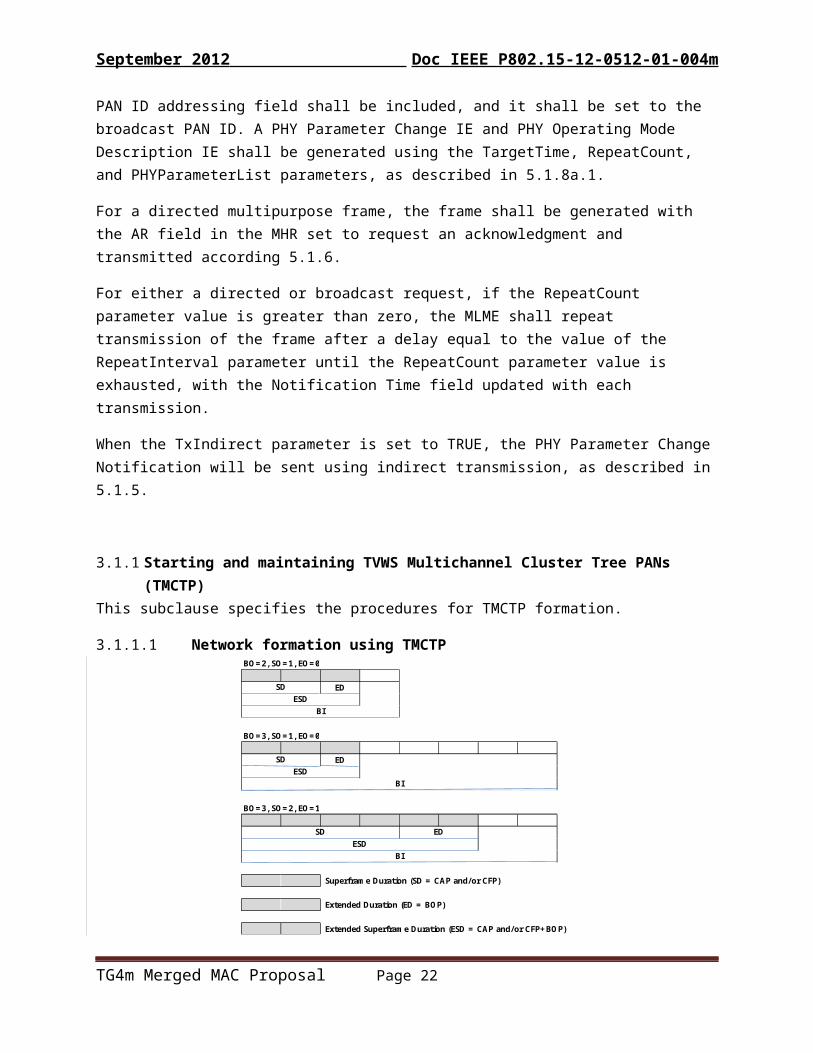
The SD and BI of the TMCTP superframe are same as described in 5.1.1.1. The MAC PIB attribute macTMCTPExtendedOrder describes the extended length of the active portion of the superframe. The value of macTMCTPExtendedOrder, and the extended duration, ED, are related as follows:
ED = aBaseSuperframeDuration × 2macTMCTPExtendedOrder
= aBaseSlotDuration ×( aNumSuprframeSlots × 2macTMCTPExtendedOrder )
for
0 ≤ macTMCTPExtendedOrder ≤ (macBeaconOrder- macSuperframeOrder) ≤ macBeaconOrder ≤ 14
The ED of each TMCTP superframe shall be divided into aNumSuprframeSlots × 2macTMCTPExtendedOrder equally spaced slots of duration aBaseSlotDuration and is composed of beacon only period (BOP). The BOP consists of DBSs. Each DBS is composed of one or more base slots, which are aBaseSlotDuration in
TG4m Merged MAC Proposal Page 10
September 2012 Doc IEEE P802. 15-12-0512-01-004m
length. The extended duration of the active portion of each TMCTP superframe includes the base superframe duration, SD, and the extended duration for the BOP, ED:
ESD = SD + ED.
An example of a TMCTP superframe structure is shown in Figure 3, according to the macBeaconOrder, the macsuperframeOrder and the macTMCTPExtendedOrder as shown in the figure.
1 2 3 4 5 6 7 8 9 10 11 12 13 14 15
beacon interval (BI)
0-4 5-7 8-11 12-150
extended superframe duration (ESD)
Beacon Beacon
CAP CFP BOP
superframe duration (SD) extended duration (ED)
BO=2, SO=1, EO=0
ED
BO=3, SO=1, EO=0
ED
BO=3, SO=2, EO=1
Superframe Duration (SD = CAP and/or CFP)
Extended Duration (ED = BOP)
Extended Superframe Duration (ESD = CAP and/or CFP+BOP)
BI
SD EDESD
BI
SDESD
BI
SDESD
Figure 3: An example of the TMCTP superframe structure
5.1.2 Starting and maintaining PANs
5.1.3 Association and disassociation
5.1.4 Synchronization
5.1.5 Transaction handling
5.1.6 Transmission, reception and acknowledgementAdd following text at the end of section 5.1.6 Transmission, reception, and acknowledgement
TG4m Merged MAC Proposal Page 11

September 2012 Doc IEEE P802. 15-12-0512-01-004m
5.1.6.7 Direct device-to-device data transfer
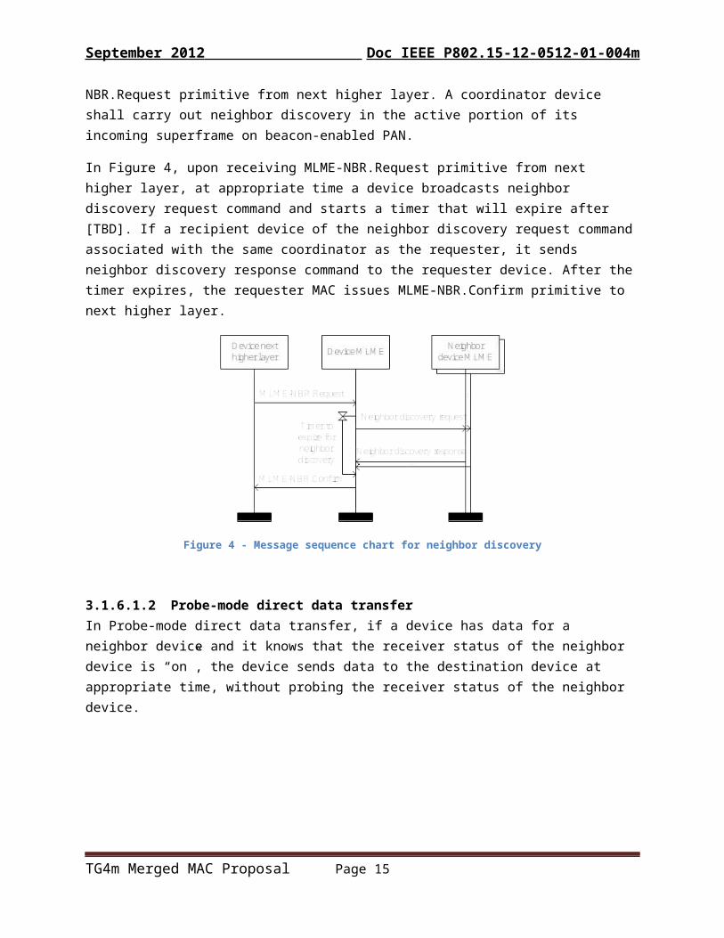
5.1.6.7.1 Neighbor discoveryNeighbor discovery may be required for direct device-to-device data transfer. A device may carry out neighbor discovery after association with its coordinator, at appropriate time upon receiving MLME-NBR.Request primitive from next higher layer. A coordinator device shall carry out neighbor discovery in the active portion of its incoming superframe on beacon-enabled PAN.
In Figure 4, upon receiving MLME-NBR.Request primitive from next higher layer, at appropriate time a device broadcasts neighbor discovery request command and starts a timer that will expire after [TBD]. If a recipient device of the neighbor discovery request command associated with the same coordinator as the requester, it sends neighbor discovery response command to the requester device. After the timer expires, the requester MAC issues MLME-NBR.Confirm primitive to next higher layer.
Figure 4 - Message sequence chart for neighbor discovery
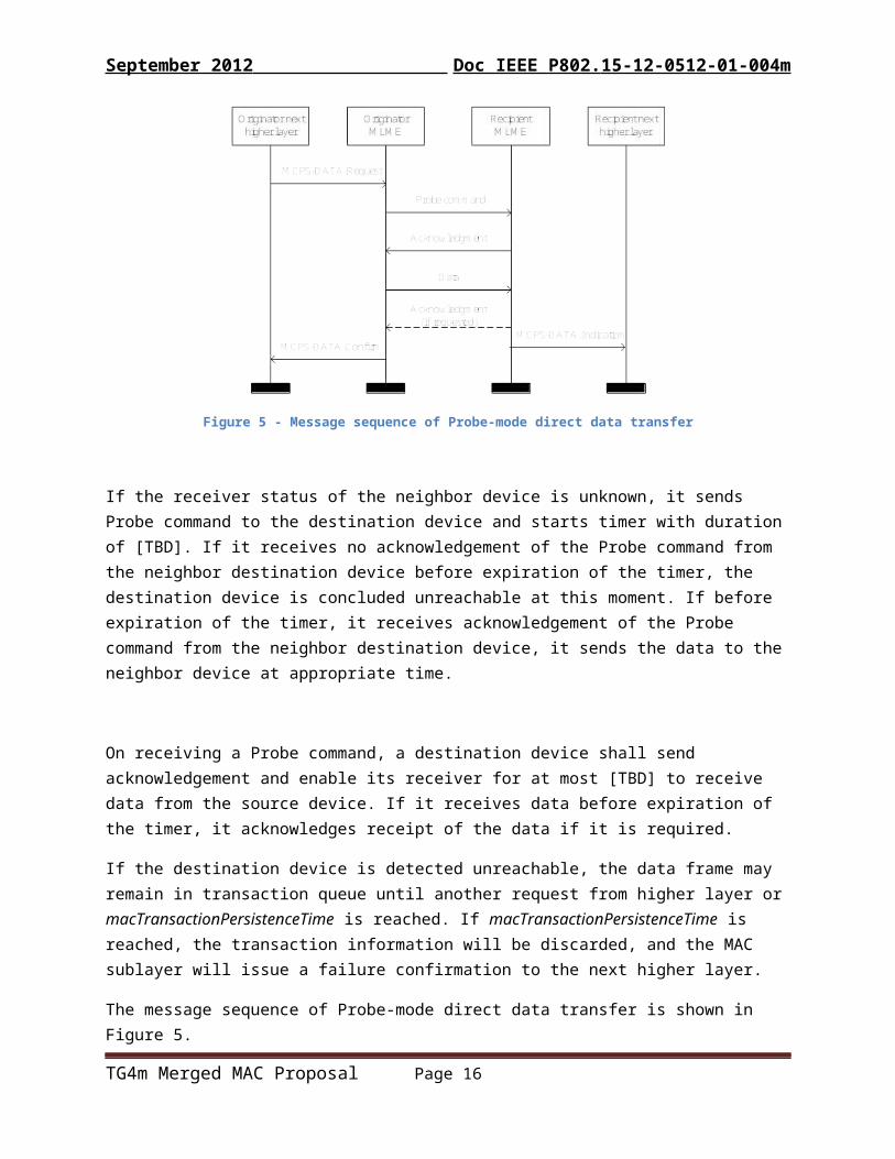
5.1.6.7.2 Probe-mode direct data transferIn Probe-mode direct data transfer, if a device has data for a neighbor device and it knows that the receiver status of the neighbor device is “on”, the device sends data to the destination device at appropriate time, without probing the receiver status of the neighbor device.
TG4m Merged MAC Proposal Page 12

September 2012 Doc IEEE P802. 15-12-0512-01-004m
Figure 5 - Message sequence of Probe-mode direct data transfer
If the receiver status of the neighbor device is unknown, it sends Probe command to the destination device and starts timer with duration of [TBD]. If it receives no acknowledgement of the Probe command from the neighbor destination device before expiration of the timer, the destination device is concluded unreachable at this moment. If before expiration of the timer, it receives acknowledgement of the Probe command from the neighbor destination device, it sends the data to the neighbor device at appropriate time.
On receiving a Probe command, a destination device shall send acknowledgement and enable its receiver for at most [TBD] to receive data from the source device. If it receives data before expiration of the timer, it acknowledges receipt of the data if it is required.
If the destination device is detected unreachable, the data frame may remain in transaction queue until another request from higher layer or macTransactionPersistenceTime is reached. If macTransactionPersistenceTime is reached, the transaction information will be discarded, and the MAC sublayer will issue a failure confirmation to the next higher layer.
The message sequence of Probe-mode direct data transfer is shown in Figure 5.
5.1.6.7.3 Polling-mode direct data transferWith Polling-mode direct data transfer, when a device’s MAC sublayer receives MLME-POLL.request primitive from next higher layer, it sends data request command to a target neighbor device at appropriate time and starts a timer with duration of [TBD].
On receiving a data request command, a device shall send acknowledgement to confirm successful reception of the command and indicate whether it has data pending for the polling neighbor.
TG4m Merged MAC Proposal Page 13

September 2012 Doc IEEE P802. 15-12-0512-01-004m
If before sending the acknowledgement of data request command, the polled device is able to determine that it has data pending for the polling device, it sets the Frame Pending field of the acknowledgement to one. If it is able to determine that it has no data pending for the polling device, it sets the Frame Pending field of the acknowledgement to zero. If it has no enough time to determine whether it has data pending for the polling device, it sets the Frame Pending field to one.
If before expiration of the timer, the polling device receives no acknowledgement of the data request command, it concludes that the neighbor device is not reachable at this moment. The polling device MAC sublayer shall issue a failure confirmation to next higher layer.
If before expiration of the timer, the polling device receives acknowledgement with the Frame Pending field set to zero, it concludes that there is no data pending at the neighbor device.
If before expiration of the timer, the polling device receives acknowledgement with the Frame Pending field set to one, it shall enable it receiver for at most [TBD] to receive the corresponding data from the neighbor device. If the polling device does not receive a data frame from the neighbor device within [TBD] or if the polling device receives a data frame from the neighbor device with a zero length payload, it shall conclude that there are no data pending at the neighbor device. If the polling device does receive a data frame from the neighbor device, it shall send an acknowledgment frame, if requested, thus confirming receipt of the data frame.
If the Frame Pending field of the data frame received is one, then the neighbor device has more data pending. In this case it may extract the data by sending a new data request command to the neighbor device.
The message sequence of Polling-mode direct data transfer is shown in Figure 6.
Figure 6: Message sequence of Polling-mode direct data transfer
TG4m Merged MAC Proposal Page 14
September 2012 Doc IEEE P802. 15-12-0512-01-004m
5.1.6.7.4 Broadcast-mode direct data transferIn Broadcast-mode direct data transfer, upon receiving higher layer MCPS-DATA.Request primitive with address of broadcast, the device broadcasts the data frame at appropriate time, [TBD]. The AR field of the data frame shall be set to indicate no acknowledgement requested. Figure 7 shows message sequence of broadcast-mode direct data transfer.
Figure 7 - Message sequence of Broadcast-mode direct data transfer
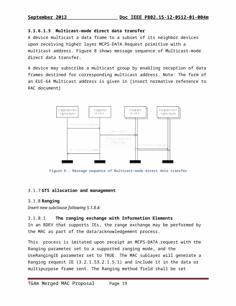
5.1.6.7.5 Multicast-mode direct data transferA device multicast a data frame to a subset of its neighbor devices upon receiving higher layer MCPS-DATA.Request primitive with a multicast address. Figure 8 shows message sequence of Multicast-mode direct data transfer.
A device may subscribe a multicast group by enabling reception of data frames destined for corresponding multicast address. Note: The form of an EUI-64 Multicast address is given in [insert normative reference to RAC document]
Figure 8 - Message sequence of Multicast-mode direct data transfer
TG4m Merged MAC Proposal Page 15
September 2012 Doc IEEE P802. 15-12-0512-01-004m
5.1.7 GTS allocation and management
5.1.8 RangingInsert new subclause following 5.1.8.4:
5.1.8.5 The ranging exchange with Information ElementsIn an RDEV that supports IEs, the range exchange may be performed by the MAC as part of the data/acknowledgement process.
This process is imitated upon receipt an MCPS-DATA.request with the Ranging parameter set to a supported ranging mode, and the UseRangingIE parameter set to TRUE. The MAC sublayer will generate a Ranging request IE (5.2.4.34.1) and include it in the data or multipurpose frame sent. The Ranging method field shall be set according to the RangingMethod parameter of the request. The Range message sequence number field shall be incremented with each MCPS-DATA.request with ranging enabled. The AR field of the FCF shall be set to request acknowledgment. The Timestamp parameter will be included in the generated MCPS-DATA.confirm.
When a data or multipurpose frame containing a Ranging request IE (5.2.4.34.1) is received by an RDEV that supports IEs, the receive Timestamp is captured and a Ranging response IE (5.2.4.34.2) is included in the Acknowledgement. The Response TX-timestamp field of the Ranging response IE is set to the local time reference when the Acknowledgement is transmitted. If the Ranging method field of the received Ranging Request IE indicates a two-way ranging request, the Request RX-timestamp field is set to the Timestamp captured when the packet containing the request was received.
Upon receipt of the Acknowldgement by the originating device, the Timestamp parameters of the MCPS-DATA.confirm are set according to the contents of the Ranging response IE.
Note: 5.1.8a below is included in the 802.5.4j and 802.15.4k drafts currently in ballot. It is repeated here as an aid to the reader and is not part of this amendment
5.1.8a PHY parameter change notification procedure
This procedure is initiated through the MLME-PHY-OP-SWITCH.request primitive, as described in 6.2.22.1, in order to signal one or more peer devices the intention to switch operating band, channel, or other PHY-specific operational parameter.
The change of PHY operating parameters in the originating or receiving device is done by a higher layer entity, using the appropriate MAC sublayer management entity (MLME) services. The procedure for determining when such a change is to be made is out of scope of this standard.
TG4m Merged MAC Proposal Page 16

September 2012 Doc IEEE P802. 15-12-0512-01-004m
The following subclauses describe a method to broadcast the change notification periodically in beacons, and a method using multipurpose frames, which may be used to direct the change notification to a single peer entity or to broadcast aperiodically.
5.1.8a.1 Signaling using periodic beacons
This method is initiated by the reception of the MLME-PHY-OP-SWITCH.request primitive with the SignalMethod parameter value set to USE_BEACON. The method requires that the enhanced beacon feature is supported and that the device is the PAN coordinator and using enhanced beacons.
A PHY Parameter Change IE (5.2.4.29) shall be generated and appended to the next outgoing periodic beacon. The Effective Time of Change field of the IE shall be set to the value of the TargetTime parameter of the MLME-PHY-OP-SWITCH.request primitive. The Notification Time field shall be updated with each transmission to the local time of the device. A PHY Operating Mode Description IE (5.2.4.27) shall be generated according to the values in the PHYParameterList and appended to the beacon following the PHY Parameter Change IE.
If the value of the RepeatCount parameter is non-zero, then the generated IEs shall be included in each periodic beacon subsequently generated until the repeat count is exhausted, or until the value in the TargetTime parameter has elapsed. If the RepeatCount parameter is zero, the generated IEs shall be included in only the next periodic beacon.
5.1.8a.2 Signaling using multipurpose frames
This method is initiated by the reception of the MLME-PHY-OP-SWITCH.request primitive with the SignalMethod parameter value set to USE_MP. The method requires that the multi-purpose frame (5.2.2.6) is supported.
The device shall generate a multipurpose frame with the addressing fields set according to the DeviceAddrMode and DeviceAddr parameter values in the MLME-PHY-OP-SWITCH.request primitive. If the DeviceAddress parameter contains the broadcast address, then only the PAN ID addressing field shall be included, and it shall be set to the broadcast PAN ID. A PHY Parameter Change IE and PHY Operating Mode Description IE shall be generated using the TargetTime, RepeatCount, and PHYParameterList parameters, as described in 5.1.8a.1.
For a directed multipurpose frame, the frame shall be generated with the AR field in the MHR set to request an acknowledgment and transmitted according 5.1.6.
For either a directed or broadcast request, if the RepeatCount parameter value is greater than zero, the MLME shall repeat transmission of the frame after a delay equal to the value of the RepeatInterval parameter until the RepeatCount parameter value is exhausted, with the Notification Time field updated with each transmission.
When the TxIndirect parameter is set to TRUE, the PHY Parameter Change Notification will be sent using indirect transmission, as described in 5.1.5.
TG4m Merged MAC Proposal Page 17

September 2012 Doc IEEE P802. 15-12-0512-01-004m
5.1.14 Starting and maintaining TVWS Multichannel Cluster Tree PANs (TMCTP)This subclause specifies the procedures for TMCTP formation.
5.1.14.1 Network formation using TMCTPBO=2, SO=1, EO=0
ED
BO=3, SO=1, EO=0
ED
BO=3, SO=2, EO=1
Superframe Duration (SD = CAP and/or CFP)
Extended Duration (ED = BOP)
Extended Superframe Duration (ESD = CAP and/or CFP+BOP)
BI
SD EDESD
BI
SDESD
BI
SDESD
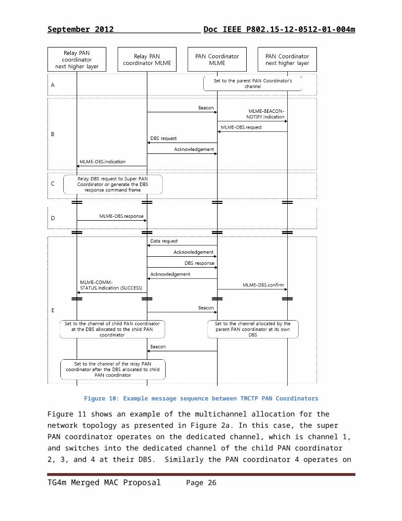
shows an example with suggested message sequence for TMCTP formation between the SPC, which is the parent PAN coordinator, and a child PAN Coordinator. The example is explained as follows:
In step A, the SPC obtains the list of available TVWS channels from the Geolocation Database (GDB) through the Internet. The protocol used to access the GDB over the internet is outside the scope of this standard. Alternately, the SPC may obtain the list of available TVWS channels from another device (Fixed, Mode II or Mode I Device). The SPC maps the TVWS channels to corresponding PHY channels and selects one of the available PHY channels, and transmits its beacon through that channel. The child PAN coordinator completes the scan procedure over all PHY channels and association procedures with the SPC, and is waiting the beacon of the SPC.
In step B the SPC transmits an enhanced beacon containing a TMCTP Extended Superframe Specificiation IE (xref). Upon successful reception of the beacon from the SPC, the child PAN coordinator may request a DBS allocation sending a DBS request (xref) to the SPC. Upon receiving the DBS request, the SPC will allocate a DBS slot and channel, and generate a DBS response to report the slot and channel allocated (the request is successful in this example).
In step C of the example, the SPC indicates pending data for the child PAN coordinator in its beacon. The child PAN coordinator sends the data request command frame. Upon receiving the data request, the SPC replies with the DBS response generated in step B.
In step D, the SPC sends its own beacon frame. The SPC switches into the channel allocated to the PAN coordinator and receives the beacon frame from the PAN coordinator.
TG4m Merged MAC Proposal Page 18
September 2012 Doc IEEE P802. 15-12-0512-01-004m
In step E, upon receiving the beacon frame during the slot allocated to the child PAN coordinator on the allocated channel, the SPC switches into its own dedicated channel.
During the CAP of SPC, each PAN coordinator sends DBS requests to the SPC and receives DBS response from the SPC. The SPC switches into the allocated channel before the allocated DBS slot time to the PAN coordinator. Each PAN coordinator forms an independent PAN by transmitting its beacon in the allocated DBS slot.
Figure 9 - Example message sequence between the SPC and the PAN coordinator
Figure 10 provides another example for TMCTP formation between the PAN coordinators, one is the parent PAN coordinator and the other is the child PAN Coordinator.
TG4m Merged MAC Proposal Page 19

September 2012 Doc IEEE P802. 15-12-0512-01-004m
In step A, the child PAN coordinator performs a scan and association with the parent PAN coordinator, and is waiting for the beacon of the parent PAN coordinator.
In step B, the parent PAN coordinator sends an enhanced beacon containing an Extended Superframe Specification IE (5.2.4.35). Upon successful reception of the beacon from the parent PAN coordinator, the child PAN coordinator requests a channel and a slot by using the DBS request sent to the parent PAN coordinator. Upon receiving the DBS request, the parent PAN coordinator directly generates the DBS response frame reporting the slot and a channel allocated, or it or sends the DBS request command frame to the SPC and then receives the DBS response command frame from the SPC.
In step C, the parent PAN coordinator sends a beacon. The parent PAN coordinator switches into the channel allocated to the child PAN coordinator and receives the beacon frame from the child PAN coordinator.
In step D, upon receiving the beacon frame during the allocated slot to the child PAN coordinator on the allocated channel to the child PAN coordinator, the parent PAN coordinator switches into its own dedicated channel.
During CAP of the parent PAN coordinator, which has a relay capability or a channel allocation capability, each child PAN coordinator sends the DBS request to the parent PAN coordinator and receives the DBS response from the parent PAN coordinator. The parent PAN coordinator uses the allocated channel during the allocated DBS slot for each child PAN coordinator. Each child PAN coordinator manages its own WPAN by transmitting a beacon at the allocated DBS slot time.
TG4m Merged MAC Proposal Page 20
September 2012 Doc IEEE P802. 15-12-0512-01-004m
Figure 10: Example message sequence between TMCTP PAN Coordinators
Figure 11 shows an example of the multichannel allocation for the network topology as presented in Figure 2a. In this case, the super PAN coordinator operates on the dedicated channel, which is channel 1, and switches into the dedicated channel of the child PAN coordinator 2, 3, and 4 at their DBS. Similarly the PAN coordinator 4 operates on the dedicated channel, which is channel 4, and switches into the dedicated channel of the child PAN coordinator 5 at its DBS.
TG4m Merged MAC Proposal Page 21
September 2012 Doc IEEE P802. 15-12-0512-01-004m
Bcn CAP CFP channel 1DBS channel 2
DBS channel 3DBS channel 4
Bcn CAP CFP channel 1channel 2
Bcn CAP CFP channel 1channel 3
Bcn CAP CFP channel 1channel 4
DBS channel 5
channel 4Inactive channel 5
Super PAN Coordinator 1
BOP Inactive
PAN Coordinator 2 Active (Bcn, CAP, or CFP) Inactive
PAN Coordinator 3 Active (Bcn, CAP, or CFP) Inactive
PAN Coordinator 4 Active (Bcn, CAP, or CFP) InactiveBOP
PAN Coordinator 5 Active (Bcn, CAP, or CFP)Inactive Active
Figure 11 - Example TMCTP BOP allocation
5.1.15 TVWS Power saving (TVWSPS)This subclause defines a scalable and symmetrical power saving model for a wide range of LR-WPAN applications operating in TVWS.
A TVWS device may be either an initiating device or a responding device. A responding device switches on its receiver during periodic listening periods macTVWSPSListeningInterval apart, each with listening duration macTVWSPSListeningDuration. In between listening periods, the responding device may be in sleep mode with the receiver disabled. To poll the responding device, an initiating device transmits frames containing a TVWS power saving (TVWSPS) IE followed by a channel listening period at macTVWSPSPollingInterval, for total duration macTVWSPSPollingDuration or until receiving an acknowledgement frame, whichever occurs first.
The value of macTVWSPSPollingInterval should be less than or equal to macTVWSPSListeningDuration and macTVWSPSPollingDuration should be more than or equals to macTVWSPSListeningInterval. The TVWSPS IE may be included in an enhanced beacon, data or multi-purpose frame.
An initiating or responding device may also indicate the required time for completing the transaction in the transaction duration field of the generated TVWSPS IE.
When generating the TVWSPS ID, the Rendezvous time field shall be set to the value of macTVWSPSRendezvousTime and the Transaction duration field shall be set to the value of macTVWSPSTransDuration.
Upon receiving a frame with a TVWSPS IE, the responding device switches on an ad-hoc listening period to receive the data from the initiating device at the Rendezvous time indicated in the received TVWS IE, and transmits the data requested by the initiating device at indicated rendezvous time.
TG4m Merged MAC Proposal Page 22

September 2012 Doc IEEE P802. 15-12-0512-01-004m
Two illustrative examples of the TVWSPS protocol is given in Figure 12. In the first example the initiating device 1 has pending data to transmit to the responding device. In the second, Initiating device 2 is requesting data from the responding device.
Figure 12: TVWS Power Saving Example
5.2 MAC frame formats
5.2.2 Format of individual frame types
5.2.2.1 Beacon frame format
5.2.2.1.1a Information elements (IEs) field
[add to Table 3b for query/response via EBs]
5.2.4 Information Elements
5.2.4.1 Header information elements[add to table 4b as needed]
TG4m Merged MAC Proposal Page 23

September 2012 Doc IEEE P802. 15-12-0512-01-004m
5.2.4.4 MLME information elements Add the following rows at the end of ttable 4d:
Table 4d
Sub-ID Value
Content Length Name Description
PHY Parameter Change IE defined in 5.2.4.29TBA 12 PS IE TVWS Power Saving IE, defined in 5.2.4.30.TBA variable TVWS PHY Operating Mode
Description IEDescription of a specific TVWS PHY operating mode, defined in 5.2.4.31.
TBA variable TVWS device capabilities IE IE used to exchange TVWS PHY specific device capabilities, defined in 5.2.4.32.
TBA TVWS device identification IE5.2.4.33.2TBA TVWS device location IE, defined in 5.2.4.33.3TBA TVWS channel information query
request/response IE, defined in 5.2.4.33.4TBA Network Channel Control IE defined in
5.2.4.33.5TBA Channel Timing Management IE, defined in
5.2.4.33.7TBA Channel map verification IE5.2.4.33.8
Ranging request IE, defined in 5.2.4.34.1 Ranging response IE, defined in 5.2.4.34.2TMCTP Extended Superframe Specification , defined in 5.2.4.35
Editor’s Note: ID values are assigned by the Working Group 15 Assigned Numbering Authority prior to submitting draft for publication.
Note: 5.2.4.29 is defined in the draft 15.4j and 15.4k and is considered part of the base standard for this amendment; this is included here as an aid to the reader only, and will not be part of the 15.4m amendment.
5.2.4.29 PHY Parameter Change IEThe PHY Parameter Change IE is used by a device to notify a peer device or devices to switch operating band, channel, or other PHY-specific operational parameter. The IE may be used in a directed frame to initiate a change between specific peers, or it may be used in periodic beacons to affect a coordinated change among members of a PAN. The specific procedures for affecting a change are out of the scope of this standard. The PHY Parameter Change IE shall be formatted as illustrated in Figure
Octets: 4 4Effective Time of Change Notification Time
TG4m Merged MAC Proposal Page 24
September 2012 Doc IEEE P802. 15-12-0512-01-004m
Figure 13: PHY Parameter Change IE
The Effective Time of Change field shall contain a time in the future, in microseconds, when the change should occur.
The Notification Time field shall contain the local time value in the generating device at the time the frame containing the IE is generated.
The PHY Parameter Change IE shall always be followed in the frame by a valid Operating Mode Description IE describing the desired change.
Insert the following new subclauses following 5.2.4.29:
5.2.4.30 TVWS Power Saving (TVWSPS) IEThe TVWSPS IE is used by a device to initiate a TVWSPS transaction. The content of the IE shall be formatted as shown in Figure 14.
Octets: 1 3 3 3 2PS Control Periodic Listening
PeriodPeriodic Listening
DurationRendezvous
TimeMaximum
Transaction DurationFigure 14: TVWSPS IE Content
The PS Control field indicates the types of operation intended by the source device. A value of 0 indicates the announcement of a responding device’s Periodic Listening Interval and Periodic Listening Duration. A value of 1 indicates that an initiating device has pending data to be transmitted to the responding data. A value of 2 indicates that an initiating device is requesting data from the responding device. All other values are reserved.
The Periodic Listening Interval field is the time between the start of a periodic listening duration to the start of the subsequent periodic listening duration (see 5.1.14) in milliseconds, with a range of from 0 to 16777215 milliseconds. When generated this field shall be set to the value of macTVWSPSListeningInterval.
The Periodic Listening Duration field is the time between the start and the end of a periodic listening period, in milliseconds, with a range of 0 to 16777215 milliseconds. When generated this field shall be set to the value of macTVWSPSListeningDuration.
The Rendezvous time field is the time in milliseconds between the end of the acknowledgement frame sent by a responding device or received by an initiating device, and the start of the data transaction between the two devices. When generated the value of this field is set to macPSRendezvousTime, with a valid range of from 0 to 16777215 milliseconds.
The Transaction Duration field is the time needed complete the transaction between the initiating and responding devices. When generated this field is set to the value of macTVWSPSTransDuration, with a valid range of from 0 to 65535 milliseconds.
TG4m Merged MAC Proposal Page 25
September 2012 Doc IEEE P802. 15-12-0512-01-004m
5.2.4.31 TVWS PHY operating mode description IEThe TVWS PHY Operating Mode Description IE is used with the PHY Parameter Change IE (5.2.4.29) to signal dynamically a change in operating channel, band or other PHY operating parameter when the resulting change will be to configuration defined by the TVWS PHY. The TVWS PHY Operating Mode Description IE is an MLME IE as defined in 5.2.4.5. The content field shall be formatted as shown in Figure 15.
TVWS PHY Operating Mode DescriptionFigure 15: TVWS PHY operating mode description IE content
The TVWS PHY operating mode description field shall be encoded as shown in Table 1. The specific parameters are encoded depending the PHY type indicated.
Table 1 - TVWS PHY operating mode description field encoding
Bit Number
Description
0:7 TVWS Band ID8:15 TVWS Channel ID
The TVWS Channel ID allocated by the TVWS database (see annex Q.zzz)1
16:23 PHY Channel ID The channel identification for the 802.15.4 TVWS PHY channel as defined in 8.1.2.
24:25 PHY Type Selector:0 = TVWS FSK PHY (20.1)1 = TVWS OFDM PHY (20.2)2 = TVWS NB-OFDM PHY (20.3)3 = Reserved
26:31 FSK Operating Parameters: when PHY Type Selector is set to 0. Bit Number26 FEC Enabled 27 Interleaving enabled 28 Spreading enabled 29:30 FSK Operating Mode [symbol rate, channel spacing – xref to PHY clause]31 ReservedOFDM Operating Parameters when PHY Type selector is set to 126:28 Modulation order: TBD
29:31 Reserved
NB-OFDM
26:28 Modulation order: TBD
29:31
1 We may reduce the TVWS Channel ID and PHY Channel ID to a single field depending on how the PHY channel assignments are specified. The field size can also be adjusted when we have complete PHY specifications.
TG4m Merged MAC Proposal Page 26

September 2012 Doc IEEE P802. 15-12-0512-01-004m
Note: The content of this table is illustrative: the actual parameters included and thus bit field sizes will be determined when the PHY specifications are complete enough to complete the parameters that should be signaled.
5.2.4.32 TVWS device capabilities IEThe following IE declares the TVWS capabilities supported by a device. The presence of this IE in a transmitted frame indicates that the device supports operation of a TVWS PHY. The IE content shall be as shown in Figure 16.
[Note: the details of this IE will be change when the PHY specification is completed]
Octets: 1 2 2 VariableTVWS PHY type TVWS supported bands TVWS supported PHY
featuresTVWS channels supported
Figure 16 - TVWS device capabilities IE
The TVWS PHY type field indicates the PHY type being described the IE. This field shall be set to one of the non-reserved values shown in Table 4v.
Table 2: TVWS PHY Type Field Values
Value Description1 TVWS FSK PHY2 TVWS OFDM3 TVWS NB-OFDM4-255 Reserved
The TVWS supported bands field is a bitmap indicating the supported TVWS bands. A value of one indicates that the band is supported, and zero indicates the band is not supported. The supported TVWS bands supported shall be encoded as shown in Table 3. The device shall indicate as supported only those TVWS bands that are implemented and defined for the indicated PHY type [add cross reference to TVWS PHY clause].
Table 3 TVWS PHY Bands Supported Field Encoding
Bit number Description0 TVWS Band USA1 TVWS Band UK2 TVWS Band Japan3 TVWS Band Canada4 TVWS Band Korea5 - 31 Reserved
TG4m Merged MAC Proposal Page 27

September 2012 Doc IEEE P802. 15-12-0512-01-004m
The TVWS supported features field indicates the supported PHY features of a TVWS PHY. The field shall be encoded as shown in Table 4.
Table 4: TVWS PHY Features Supported Field Encoding
Bit # Description0
To be completed when the TVWS PHYs are further defined1…
The Channels Supported field is a set of channel maps that shall be formatted as described in figurexxx.
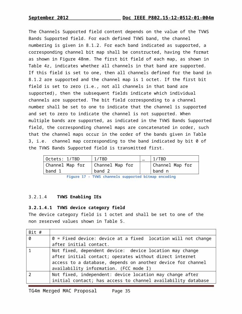
The Channels Supported field content depends on the value of the TVWS Bands Supported field. For each defined TVWS band, the channel numbering is given in 8.1.2. For each band indicated as supported, a corresponding channel bit map shall be constructed, having the format as shown in Figure 48nm. The first bit field of each map, as shown in Table 4z, indicates whether all channels in that band are supported. If this field is set to one, then all channels defined for the band in 8.1.2 are supported and the channel map is 1 octet. If the first bit field is set to zero (i.e., not all channels in that band are supported), then the subsequent fields indicate which individual channels are supported. The bit field corresponding to a channel number shall be set to one to indicate that the channel is supported and set to zero to indicate the channel is not supported. When multiple bands are supported, as indicated in the TVWS Bands Supported field, the corresponding channel maps are concatenated in order, such that the channel maps occur in the order of the bands given in Table 3, i.e. channel map corresponding to the band indicated by bit 0 of the TVWS Bands Supported field is transmitted first.
Octets: 1/TBD 1/TBD … 1/TBDChannel Map for band 1 Channel Map for band 2 Channel Map for band n
Figure 17 - TVWS channels supported bitmap encoding
5.2.4.33 TVWS Enabling IEs
5.2.4.33.1TVWS device category fieldThe device category field is 1 octet and shall be set to one of the non reserved values shown in Table 5.
Bit #0 0 = Fixed device: device at a fixed location will not change after initial contact.1 Not fixed, dependent device: device location may change after initial contact; operates
without direct internet access to a database, depends on another device for channel availability information. (FCC mode I)
2 Not fixed, independent: device location may change after initial contact; has access to channel availability database (FCC mode2)
3 - 255 TBD or reserved Table 5: Device category
TG4m Merged MAC Proposal Page 28

September 2012 Doc IEEE P802. 15-12-0512-01-004m
5.2.4.33.2TVWS device identification IEThe device identification may contain one of several types if identification, including a regulator assigned device approval identification, a manufactures serial number, or implementation specific value. A number of IDs may be included in a single MAC frame as required. The format is shown in Figure 18.
Octets: 1 VariableID type Device ID
Figure 18: TVWS device identification IE content
The ID Type field shall be set to one of the non-reserved values in Table 6.
ID type value Description
0 US specific regulator assigned ID (FCC ID)1 UK specific regulator assigned ID 2 Canada specific regulator assigned ID3 Japan specific regulator assigned ID 4 Korea specific regulator assigned ID5 Manufactures serial number6 General (implementation specific value)7 - 255 Reserved
Table 6:ID Type field values
For ID types indicated as regulator assigned, the Device ID is comprised of two fields, formatted as shown in Figure 19.
Octets: 1 VariableDevice Category ID string
Figure 19: Regulator assigned ID format
[add device example category table]
The ID string field is a counted string as shown in Figure 20.
Octets: 1 VariableLength Array of octets
Figure 20: Counted string field
The length field specifies the number of octets that follow in the array of octets field. The encoding of characters into the array of octets is outside the scope of this standard.
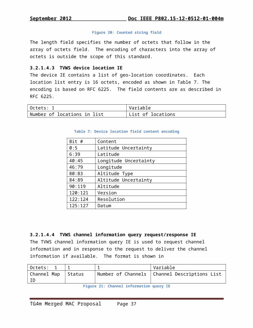
5.2.4.33.3TVWS device location IEThe device IE contains a list of geo-location coordinates. Each location list entry is 16 octets, encoded as shown in Table 7. The encoding is based on RFC 6225. The field contents are as described in RFC 6225.
Octets: 1 VariableNumber of locations in list List of locations
TG4m Merged MAC Proposal Page 29

September 2012 Doc IEEE P802. 15-12-0512-01-004m
Table 7: Device location field content encoding
Bit # Content0:5 Latitude Uncertainty6:39 Latitude40:45 Longitude Uncertainty46:79 Longitude80:83 Altitude Type84:89 Altitude Uncertainty90:119 Altitude120:121 Version122:124 Resolution 125:127 Datum
5.2.4.33.4TVWS channel information query request/response IEThe TVWS channel information query IE is used to request channel information and in response to the request to deliver the channel information if available. The format is shown in
Octets: 1 1 1 VariableChannel Map ID Status Number of Channels Channel Descriptions List
Figure 21: Channel information query IE
The channel map ID is incremented when the channel data is updated. When the status field indicates that this is a channel data request, the channel map ID field is set to the ID value provided when channel data was last received. If channel data has not been received the channel map ID is set to 0 in the request.
The status field indicates if this IE is a request or a response, and if a response, the nature of the response. It shall be set to one of the values in Table 8.
Status
Description
0 Channel list requested 1 Available channel list for verified for a device location
Available channel list for verified for multiple device location2 Request not successful due to device ID not verified 3 Request not successful due to device location is out of the geographic coordinate 4 Request not successful due to one or more parameters have invalid values5 Request not successful for another reason7-255 Reserved
Table 8: Channel information query status values
When the status field indicates a request, device identification IEs and a device location IE may be included in the request frame.
TG4m Merged MAC Proposal Page 30

September 2012 Doc IEEE P802. 15-12-0512-01-004m
When the status field indicates a response with available channel list for verified device location, the number of channels and channel descriptions list fields are included in the IE. For other status values these fields are not present.
The number of channels field contains the number of channel descriptions that follow in the channel descriptions list. Each entry in the channel descriptions list contains the specific information on available channels as shown in figure
Octets: 2 1 VariableTVWS Channel ID Maximum TX Power Spectrum Mask Descriptor
Figure 22: Available TVWS Channel description
The TVWS channel ID field contains a channel ID appropriate to the TVWS PHY in use as described in 8.1.2. The Maximum TX power field contains the maximum allowed transmit power, in 0.5 dBm, authorized for the channel. The Valid time field contains the time, in minutes from the time of transmission, that channel is available; a valid time of zero indicates “until further notice” (as might be used for contact verification).
The Spectrum Mask Descriptor field contents is TBD (TBD: require updates on describing spectrum mask description).
5.2.4.33.5Network Channel Control IEThe Network Channel Control IE provides a description of a particular PHY channel and shall be formatted as shown in Figure 23.
Octets: 2 VariablePHY Channel ID Spectrum Mask Descriptor
Figure 23: Available TVWS Channel description
The Spectrum Mask Descriptor field contents is TBD (TBD: require updates on describing spectrum mask description).
5.2.4.33.6TVWS channel information source description IEChannel Data Source Inforomation IE is used to advertise the availability of a device capable of providing channel availability data to peer devices. The IE is formatted as shown in
Octets: 1 16 0/8 0/4 0/1 Variable Source Info
Location Address of Known source
Known source Channel Description
Number of channel descriptions
Channel Descriptions
Figure 24: Channel information source description IE content
The Source info field is a bit map, encoded as shown in Table 9.
Bit # Description0 Indication that this device is a channel info source, and thus channel description fields are
present1 Indication of known Channel Info source address field included
TG4m Merged MAC Proposal Page 31

September 2012 Doc IEEE P802. 15-12-0512-01-004m
2 Indication that known Source Channel descriptions field present3-7 Reserved
Table 9: Source info field encoding
The location field is formatted as shown in Table 7.
The Address of known source field is present when indicated by the source info field. When present, it contains the 64-bit extended address of a device known to the transmitting device to be a source of channel availability data.
The known source channel description field is present when indicated by the source info field and contains the channel description for contacting the known source described in the address of known source field.
Number of channel descriptions indicates how many Chanel Descriptions are contained in the channel Descriptions field. This field is present only when the source info field indicates that this device is a channel data source. Channel descriptions field is present when the Number of channel descriptions field is present and not zero; each channel description is formatted as shown in Figure 22.
5.2.4.33.7Channel Timing Management IEThe content of the Channel Timing Management IE shall be formatted as shown in Figure 25.
Octets: 1 1 Variable VariableReason/Result Code Device Class Device Identification Channel Timing
InformationFigure 25: Channel Timing Management IE Content
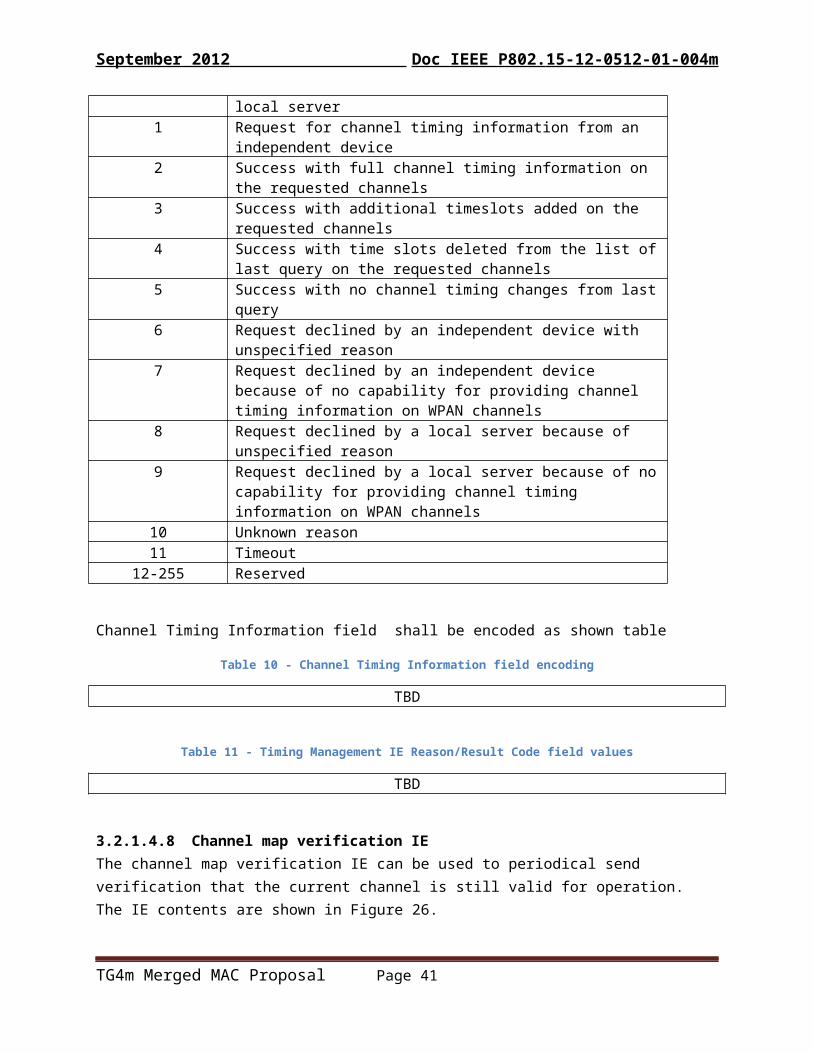
The Reason/Result Code field indicates the reason for transmitting a query request for channel schedule information. It also indicates the result of a query as successful or not, and the reason, when the query is not successful. The Reason/Result Code field values are defined in the Table 11.
Reason/Result Code field values
Description
0 Request for channel timing information from a local server1 Request for channel timing information from an independent device2 Success with full channel timing information on the requested channels 3 Success with additional timeslots added on the requested channels 4 Success with time slots deleted from the list of last query on the
requested channels5 Success with no channel timing changes from last query 6 Request declined by an independent device with unspecified reason 7 Request declined by an independent device because of no capability
for providing channel timing information on WPAN channels 8 Request declined by a local server because of unspecified reason9 Request declined by a local server because of no capability for
providing channel timing information on WPAN channels10 Unknown reason
TG4m Merged MAC Proposal Page 32

September 2012 Doc IEEE P802. 15-12-0512-01-004m
11 Timeout12-255 Reserved
Channel Timing Information field shall be encoded as shown table
Table 10 - Channel Timing Information field encoding
TBD
Table 11 - Timing Management IE Reason/Result Code field values
TBD
5.2.4.33.8Channel map verification IEThe channel map verification IE can be used to periodical send verification that the current channel is still valid for operation. The IE contents are shown in Figure 26.
Octets: 1 1Channel Map ID Valid time
Figure 26: Channel map veriication IE content
The Channel map ID field contains the ID for the channel map ID as described in 5.2.4.33.4.
The Valid time field contains the time, in minutes from the time of transmission that the channel availability data is expected to remain valid.
5.2.4.34 Ranging support IEs
5.2.4.34.1Ranging request IEThe Ranging request IE is used by an device to initiate the transfer of ranging measurements between devices. In a ranging capable device, the presence of a Ranging request IE signals the receiving MAC entity that the receive timestamp should be captured and returned to the requesting device. This IE is used in the ranging exchange described in 5.1.8.5.
The ranging request IE content is 1 octet and encoded as shown in
Octets: 1Bit #: 0 1:7
Ranging method Ranging message sequence numberFigure 27: Ranging request IE content
The ranging method field shall be set to 0 to indicate one-way ranging and set to 1 to indicate two-way ranging. The ranging message sequence number shall be set as described in 5.1.8.5.
5.2.4.34.2Ranging response IEThe Ranging response IE is encoded as shown in figure
TG4m Merged MAC Proposal Page 33

September 2012 Doc IEEE P802. 15-12-0512-01-004m
Octets: 1 0/4 4Bits: 0 1:7
Ranging method Ranging message sequence number
Request RX Timestamp Response TX Timestamp
Figure 28: Ranging response IE content
The ranging method field shall be set to 0 to indicate one-way ranging and set to 1 to indicate two-way ranging. The ranging message sequence number shall be set as described in 5.1.8.5.
The Request RX Timestamp shall be present when the ranging method field is set to two-way ranging and shall contain the time, in the responding device time reference, that the request was received. The field shall be omitted when the ranging method field is set to one-way ranging.
The Response TX timestamp shall be set to the time, in the responders time reference , when response packet is transmitted.
5.2.4.35 TMCTP Extended Superframe Specification IEThe Extended superframe Specification IE shall be formatted as illustrated in Figure 29.
Bits: 0-3 4 5 6 7Beacon Only Period Order
Reserved Dedicated Beacon Slot Allocation Capability
Channel Allocation Capability
Channel Allocation Relay Capability
Figure 29: Format of the Extended Superframe Specification IE
The Beacon Only Period Order field specifies the length of the extended duration. The relationship between the extended order and the extended duration is explained in 5.1.1.8.
The Dedicated Beacon Slot Allocation Capability field shall be set to one if the device is capable of allocating the DBS to the child PAN coordinator, it shall be set to zero otherwise.
The Channel Allocation Capability field shall be set to one if the device is capable of allocating the dedicated channel to the child PAN coordinator, it shall be set to zero otherwise.
The Channel Allocation Relay Capability field shall be set to one if the device is capable of relaying the DBS request of the child PAN coordinator, it shall be set to zero otherwise.
5.3 MAC command framesInsert into Table 5 new rows:
Table 5—MAC command frame frames
Command frame frame identifier
Command frame name RFD SubclauseTx Rx
TBA DBS request 5.3.14TBA DBS response 5.3.15
TG4m Merged MAC Proposal Page 34
September 2012 Doc IEEE P802. 15-12-0512-01-004m
TBA Neighbor discovery requestTBA Neighbor discovery responseTBA Probe
Note: Identifier values will be assigned by the 802.15 WG assigned numbering authority
5.3.4 Data request commandChange first paragraph of 5.3.4 as indicated:
The data request command is sent by a device to request data from the PAN coordinator, or a coordinator, or a neighbor device.
Add after last sentence of 5.3.4:
All TVWS devices shall be capable of transmitting and receiving this command except that a non-TVWS RFD is not required to be capable of receiving it.
5.3.14 DBS request command frameThe DBS request command is used in a TMCTP enabled PAN to request allocation of a DBS and a channel. The DBS request command shall be formatted as shown in Figure 30.
Octets: 11-25 1 4MHR Fields Command Frame Identifier DBS Request Information
Figure 30 - TMCTP DBS Request Command Frame
5.3.14.1 MHR Fields(TBD)
5.3.14.2 DBS Request information fieldThe DBS Request information field shall be encoded as shown in Figure 31.
Bits: 0:15 16:19 20:22 23 24:31Requester
Short AddressDBS Length Reserved Characteristics
TypeNumber of the
DescendantFigure 31: DBS Request information field encoding
The Requester Short Address field contains the short address of the coordinator requesting a DBS and shall be set to macShortAddress upon transmission.
The DBS Length field shall contain the number of aBaseSlotDuration being requested for a DBS.
The Characteristics Type field shall be set to one if the characteristics refer to a DBS allocation or zero if the characteristics refer to a DBS deallocation.
TG4m Merged MAC Proposal Page 35

September 2012 Doc IEEE P802. 15-12-0512-01-004m
The Number of the Descendant field indicates the actual or expected number of descendant PAN coordinators. It may be set as zero if the PAN coordinator is not clear about how many descendants it will have.
5.3.15 DBS response command frameThe DBS response command is used in a TMCTP PAN to report the results of a DBS allocation request. The DBS response command shall be formatted as shown in Figure 32.
Octets: 11-25 1 8MHR Fields Command Frame Identifier DBS Response Information
Figure 32 - TTMCTP DBS response command format
5.3.15.1 MHR Fields(TBD)
5.3.15.2 DBS Response information fieldOctets:2 1 1 1 1 1 1Requester Short Address
Allocated DBS Starting Slot
Allocated DBS Length
Allocated Channel ID
Allocated Channel Page
Starting Channel ID
Ending Channel ID
Note: the specification of channel IDs may take a different form as the TVWS PHYs are more completely defined.
The Requester Short Address field contains the short address of the coordinator requesting a DBS and shall be set to macShortAddress upon transmission.
The Allocated DBS Starting Slot field shall contain the first slot of the allocated DBS in the BOP. The unit is the aBaseSlotDuration, as described in Table 51.
The Allocated DBS Length field shall contain the length of the allocated DBS.
The Allocated Channel Number field shall contain the channel number that the coordinator intends to use for all future communications.
The Allocated Channel Page field, if present, shall contain the channel page that the coordinator intends to use for all future communications. This field may be omitted if the new channel page is the same as the previous channel page.
The Starting Channel Number field shall contain the lowest channel number, which is assigned by the parent PAN coordinator, including the SPC.
The Ending Channel Number field shall contain the highest channel number, which is assigned by the parent PAN coordinator, including the SPC.
TG4m Merged MAC Proposal Page 36
September 2012 Doc IEEE P802. 15-12-0512-01-004m
5.3.16 Neighbor discovery request commandThe neighbor discovery request command is broadcasted by a device to discover neighbor devices that are associated with the same PAN coordinator or coordinator on a beacon-enabled PAN.
The neighbor discovery request command shall be formatted as illustrated in Figure 33.
Octets: 2 1 Variable 0/5/6/10/14 1 2Frame Control
Sequence Number
Addressing Fields
Auxiliary Security Header
Command Frame Identifier
CoordAddress
MHR MAC PayloadFigure 33: Neighbor discovery request command
5.3.16.1 MHR fieldsThe Frame Pending field shall be set to zero and ignored upon reception, and the AR field shall be set to zero. The PAN ID compression field shall be set to one, and the Destination PAN identifier shall be the same of the source PAN identifier. Both source and destination addresses shall be present. The destination address shall be set to 0xffff.
5.3.16.2 CoordAddress fieldThe CoordAddress field shall be set to the short address of the coordinator that the device associated with.
5.3.17 Neighbor discovery response commandThe neighbor discovery response command is sent to a device that is discovering neighbors and associated with the same PAN coordinator or coordinator of this device, as described in 5.1.6.7.1.
The neighbor discovery request command shall be formatted as illustrated in Figure 34.
Octets: 2 1 Variable 0/5/6/10/14 1 1Frame Control
Sequence Number
Addressing Fields
Auxiliary Security Header
Command Frame Identifier
Capability information
MHR MAC PayloadFigure 34 - Neighbor discovery response command format
5.3.17.1 MHR fields Both the Frame Pending field and the AR field shall be set to zero. The PAN ID Compression field shall be set to one. Both source and destination addresses shall be present.
5.3.17.2 Capability information fieldCapability information is described in 5.3.1.2.
5.3.18 Probe commandThe probe command is sent to a neighbor device, if the device has data pending for the neighbor device and its status is unknown, as described in 5.1.6.7.2.
The probe command shall be formatted as illustrated in Figure 35.
TG4m Merged MAC Proposal Page 37

September 2012 Doc IEEE P802. 15-12-0512-01-004m
Octets: 2 1 Variable 0/5/6/10/14 1Frame Control
Sequence Number
Addressing Fields
Auxiliary Security Header
Command Frame Identifier
MHR MAC PayloadFigure 35 - Probe discovery command format
5.3.18.1 MHR fieldsThe Frame Pending field shall be set to zero, and the AR field shall be set to one.
5.5 TVWS access proceduresIn certain regulatory domains, an independent device operating in TVWS is required to communicate with a database for primary systems to obtain permission and radio resource information, prior to starting communications. A database for primary system is typically, but not limited to a Geolocation Database (GDB). When a GDB is employed as the database, an independent device shall first communicate with the GDB to obtain permission to operate in TVWS. The communication between the independent device and the GDB is not in the scope of this standard. In this case, the independent device determines its geolocation to be reported to the GDB. The GDB then provides available channels and relevant operating information. Upon receiving permission from the GDB, the independent device may start a network and enabling other devices.
The state transition diagram of a dependent device is given in the
.
TG4m Merged MAC Proposal Page 38
Received de-enabling
signal
Received enabling
signalENABLING
SETUP COMPLETED
UNENABLED
ENABLED
Channel Availability
Query success
Timeout OR
Channel Availability
Query failure

September 2012 Doc IEEE P802. 15-12-0512-01-004m
Figure 36 - State transition of a dependent device
A dependent device, prior to receiving channel availability information (such as at power on or reset condition) begins in the UNENABLED state. The device may perform a channel scan or other procedure to detect that transmissions are active on the channel and determine a suitable source of channel availability data (e.g. an independent device advertisement). Upon receiving an enabling signal (i.e. a beacon) from an independent device, the state transitions to ENABLING STEUP COMPLETED. From the ENBLING SETUP COMPLETED state, the dependent device will initiate a channel availability query (CAQ) as required by the particular regulatory domain in which it is operating. IEs are provided (xref) for the query and delivery of channel availability information. Upon successfully completed CAQ the state transitions to ENABLED. In this state, the dependent device is able to conduct data communications. If a de-enabling signal is received, the state of the dependent device transitions to UNENABLED.
5.5.12 Channel Timing Management (CTM)Channel Timing Management facilitates assessment of the available timing schedule when a channel is available. CTM is used by employing the CTM IE as in (xref)
(TBD: require more details on the CTM procedure will be provided in clause 5)
5.5.13 Network Channel Control (NCC)Network Channel Control facilitates the assessment of available PHY channel available to be occupied. NCC is used by employing the NCC IE as in (xref).
(TBD: require more details on the NCC procedure)
TG4m Merged MAC Proposal Page 39

September 2012 Doc IEEE P802. 15-12-0512-01-004m
6 MAC services
6.2 MAC management serviceInsert the following new rows into Table 8:
Name Request Indication Response ConfirmMLME-DBS X X X XMLME-NBR X X
6.2.2 Association primitives[will need parameters for new GTS options]
6.2.2.1 MLME-ASSOCIATE.request
6.2.2.2 MLME-ASSOCIATE.indication
6.2.2.3 MLME-ASSOCIATE.response
6.2.2.4 MLME-ASSOCIATE.confirm
6.2.3 Disassociation primitives [may need new parameters]
6.2.3.1 MLME- DISASSOCIATE.request
6.2.3.2 MLME- DISASSOCIATE.indication
6.2.3.3 MLME- DISASSOCIATE.response
6.2.3.4 MLME- DISASSOCIATE.confirm
6.2.4 Communications notification primitives
6.2.4.1 MLME-BEACON-NOTIFY.indication Insert Insert the following new parameters at the end of the list in 6.2.3.1 (before the closing parenthesis):
PeriodicListeningIntervalPeriodicListeningDuration RendezvousTimeTransactionTime
Insert the following new rows at the end of Table 16:
Table 16 - MLME-BEACON-NOTIFY.indication parameters
TG4m Merged MAC Proposal Page 40
September 2012 Doc IEEE P802. 15-12-0512-01-004m
Name Type Valid range DescriptionPeriodicListeningInterval Integer 0 to 16777215 Value of the Periodic listening interval
field of a received TVWSPS IE. PeriodicListeningDuration Integer 0 to 16777215 Value of the Periodic listening duration
field of a received TVWSPS IE.RendezvousTime Integer 0 to 16777215 Value of the Rendezvous time field of a
received TVWSPS IE.TransactionDuration Integer 0 to 65535 Value of the Transaction duration field of
a received TVWSPS IE.
6.2.6 GTS management primitives
6.2.6.1 MLME-GTS.request
6.2.6.2 MLME-GTS.confirm
6.2.6.3 MLME-GTS.indication
6.2.9 Primitives for specifying the receiver enable time
6.2.9.1 MLME-RX-ENABLE.request
6.2.9.2 MLME-RX-ENABLE.confirm
6.2.10 Primitives for channel scanning
6.2.10.1 MLME-SCAN.request
6.2.10.2 MLME-SCAN.confirm
6.2.12 Primitives for updating the superframe configuration
6.2.12.1 MLME-START.request
6.2.12.2 MLME-START.confirm
6.2.14 Primitives for requesting data from a coordinatorChange the 6.2.14 as indicated:
These primitives are used to request data from a coordinator. or a neighbor device directly.
6.2.14.1 MLME-POLL.requestChange 6.2.14.1 as indicated:
The MLME-POLL.request primitive prompts the device to request data from the coordinator. Or a neighbor device directly.
The semantics of this primitive are:
TG4m Merged MAC Proposal Page 41
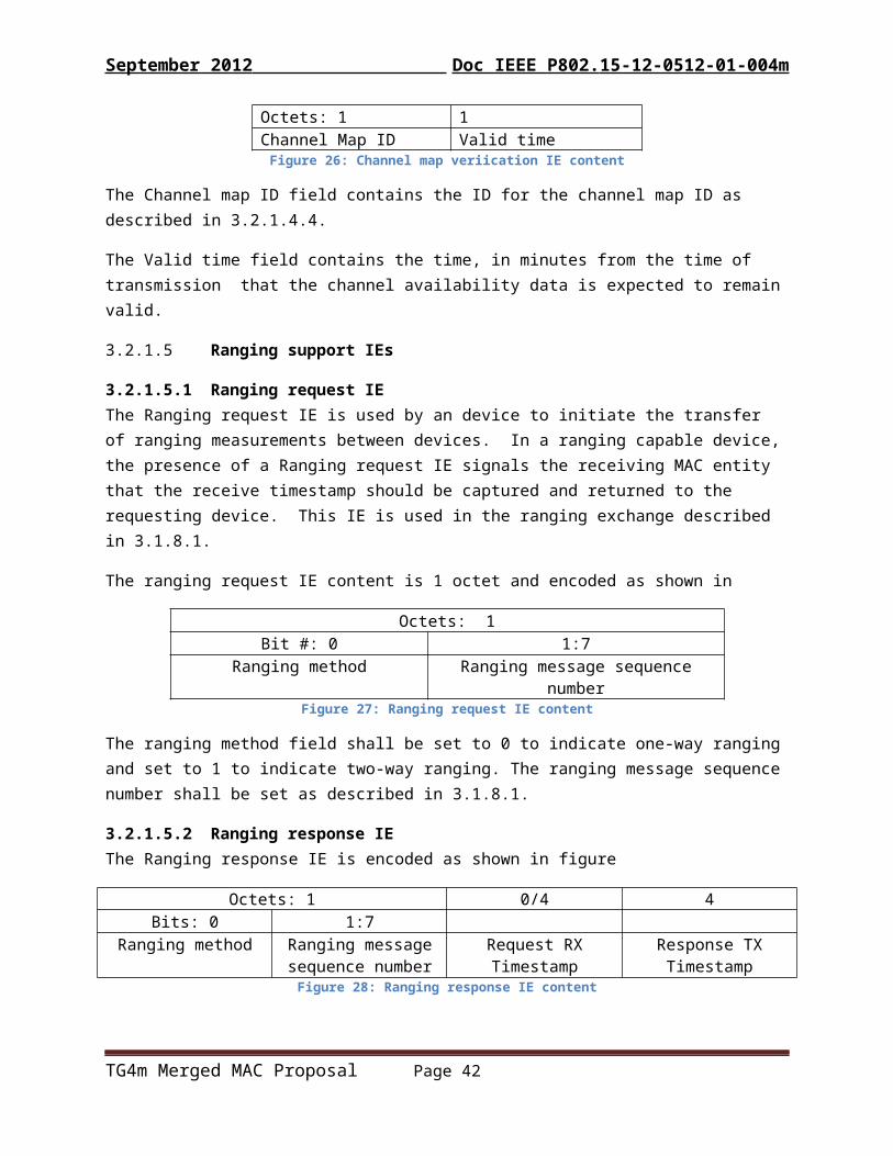
September 2012 Doc IEEE P802. 15-12-0512-01-004m
MLME-POLL.request (CoordAddrMode,CoordPANId,CoordAddress,SecurityLevel,KeyIdMode,KeySource,KeyIndex)
The primitive parameters are defined in Table 38.
On receipt of the MLME-POLL.request primitive, the MLME requests data from the coordinator, as described in 5.1.6.3, or from a neighbor device as described in 5.1.6.7.3 , depending on the address parameters. If the poll is directed to the PAN coordinator, the data request command may be generated without any destination address information present. Otherwise, the data request command is always generated with the destination address information in the CoordPANId and CoordAddress parameters.
6.2.14.2 MLME-POLL.confirmChange the first sentence of 6.2.14.2 as indicated:
The MLME-POLL.confirm primitive reports the results of a request to poll the coordinator or a neighbor device for data.
Change first 3 rows of table 38 as indicated:
CoordAddrMode Enumeration SHORT_ADDRESS,EXTENDED_ADDRESS
The addressing mode of the coordinator or the neighbor device to which the poll is intended.
CoordPANId Integer 0x0000–0xfffe The PAN identifier of the coordinator or the neighbor device to which the poll is intended.
CoordAddress Device Address As specified by the CoordAddrMode
The address of the coordinator or the neighbor device to which the poll is intended.
6.2.17 Primitives for ranging calibration (for UWB PHYs)[make ranging primitives not PHY specific]
TG4m Merged MAC Proposal Page 42

September 2012 Doc IEEE P802. 15-12-0512-01-004m
6.2.18 Primitives for Beacon Generation
6.2.19 Primitives for TSCH
6.2.19.3 MLME-SET-LINK.request
6.2.19.4 MLME-SET_LINK.confirm
[Note: 6.2.22 below is included in the 802.5.4j and 802.15.4k drafts currently in ballot. It is repeated here as an aid to the reader and is not part of this amendment]
6.2.22 Operating parameter change primitivesThese primitives support the coordination of a change in PHY operating parameters amongst peer devices.
6.2.22.1 MLME-PHY-OP-SWITCH.requestThe MLME-PHY-OP-SWITCH.request primitive is used by a device to instruct a second device to switch PHY operating parameters, including channel, band, PHY type, or other parameters specific to a PHY.
The semantics of this primitive are:
MLME-PHY-OP-SWITCH.request (DeviceAddrMode,DeviceAddr,PHYParameterList,TxIndirect,TargetTime,SignalMethod,RepeatCount,RepeatInterval,SecurityLevel,KeyIdMode,KeySource,KeyIndex
)
The primitive parameters are defined in Table 44aa.
On receipt of the MLME-PHY-OP-SWITCH.request primitive, the MLME initiates the PHY parameter change notification procedure, as defined in 5.1.8a.
If the device is the PAN coordinator of a beacon-enabled PAN that is using enhanced beacons, and the SignalMethod parameter value is USE_BEACON, the method described in 5.1.8a.1 shall be initiated.
TG4m Merged MAC Proposal Page 43

September 2012 Doc IEEE P802. 15-12-0512-01-004m
If the SignalMethod parameter value is USE_MP, the method described in 5.1.8a.2 shall be initiated. The RepeatInterval parameter value should be greater than the time required to complete a transmission, acknowledgement, and possible retransmissions.
Table 44aa—MLME-PHY-OP-SWITCH.request parameters
Name Type Valid range DescriptionDeviceAddrMode Enumeration SHORT_ADDRESS,
EXTENDED_ADDRESSThe addressing mode of the device beinginstructed to change its operating parameters.
DeviceAddr Deviceaddress
As specified by the DeviceAddrMode parameter
The address of the device being instructed to change its operating channel.
PHYParameterList List of PHY PIB attributes and values
See 9.3 A list of the PHY PIB attribute names and values representing the PHY operating parameters to be changed.
TxIndirect Boolean TRUE, FALSE TRUE if the PHY Parameter Change Notification is to be sent indirectly.
TargetTime Integer 0 – (232-1) The time, in microseconds, from the current time that the PHY operational parameter switch is to be carried out.
SignalMethod Enumeration USE_MP,USE_BEACON
The method to be used to signal intended switch.
RepeatCount Integer 0 - 127 Number of times that the PHY Parameter Change Notification should be transmitted.
RepeatInterval Integer 0 – 65535 The time, in microseconds, to delay between repeated transmissions.
SecurityLevel Integer As defined in Table 46 As defined in Table 46KeyIdMode Integer As defined in Table 46 As defined in Table 46KeySource Set of octets As defined in Table 46 As defined in Table 46KeyIndex Integer As defined in Table 46 As defined in Table 46
6.2.22.2 MLME-PHY-OP-SWITCH.confirmThe MLME-PHY-OP-SWITCH.confirm primitive is used to inform the next higher layer of the initiating device whether the channel switching notification has completed successfully.
The semantics of this primitive are:
MLME-PHY-OP-SWITCH.confirm (status,DeviceAddrMode,DeviceAddress
)
TG4m Merged MAC Proposal Page 44

September 2012 Doc IEEE P802. 15-12-0512-01-004m
The primitive parameters are defined in Table 44bb.
This primitive returns a status of either SUCCESS, if the PHY parameter change notification procedure has been completed, or the appropriate status parameter value indicating the reason for the request failure.
If the SignalMethod parameter in the request primitive is USE_BEACON, and the device is a PAN coordinator in a beacon-enabled PAN that is not using enhanced beacons, the MLME-PHY-OPSWITCH.confirm primitive shall return a status of UNSUPPORTED_FEATURE.
If the SignalMethod parameter in the request primitive is USE_BEACON, and the device is not a PAN coordinator in a beacon-enabled PAN, the MLME-PHY-OP-SWITCH.confirm primitive shall return a status of INVALID_PARAMETER.
If the SignalMethod parameter value is USE_MP, and the RepeatCount parameter value in the request primitive is greater than zero, and the RepeatInterval value is not greater than zero, the MLME-PHY-OPSWITCH.confirm primitive shall return with a status of INVALID_PARAMETER.
Table 44bb—MLME-PHY-OP-SWITCH.confirm parameters
Name Type Valid range DescriptionStatus Enumeration SUCCESS,
TRANSACTION_OVERFLOW,TRANSACTION_EXPIRED,NO_ACK,CHANNEL_ACCESS_FAILURE,COUNTER_ERROR,FRAME_TOO_LONG,UNAVAILABLE_KEY,UNSUPPORTED_SECURITY,INVALID_PARAMETER,UNSUPPORTED_FEATURE
The status of the attempt to transmit thechannel switching notificationcommand.
DeviceAddrMode Enumeration SHORT_ADDRESS,EXTENDED_ADDRESS
The addressing mode given in therequest primitive.
DeviceAddress Deviceaddress
As specified by theDeviceAddrMode parameter
The address of the device given in therequest primitive.
Insert new subclauses at the end of 6.2:
6.2.23 TMCTP DBS allocation primitivesThese primitives are used in a TMCTP enabled PAN to allocate the DBS between the parent PAN coordinator and the child PAN coordinator.
TG4m Merged MAC Proposal Page 45

September 2012 Doc IEEE P802. 15-12-0512-01-004m
6.2.23.1 MLME-DBS.requestThe MLME-DBS.request primitive is used when a child PAN coordinator requests the allocation of a DBS and a channel to a parent PAN coordinator including a super PAN coordinator.
The semantics of this primitive are:
MLME-DBS.request (RequesterCoordAddr,RequestType,DBSLength,NumberOfDescendents,SecurityLevel,KeyIdMode,KeySource,KeyIndex
)
The primitive parameters are defined in Table 12.
On receipt of the MLME-DBS.request primitive, the MLME generates a DBS request command, as defined in 5.3.14, with the DBS characteristics field set to 1 (request allocation).
The SecurityLevel parameter specifies the level of security to be applied to the DBS request command frame. Typically, the DBS request command should not be implemented using security. However, if the child PAN coordinator requesting DBS allocation shares a key with the parent PAN coordinator, then security may be specified.
Table 12 MLME-DBS.request Parameters
Name Type Valid range DescriptionRequesterCoordAddr Device Short
address0x0000-0xffff The short device
address of the (original) source requester PAN coordinator.
RequestType Enumeration ALLOCATION, DEALLOCATION
If the request is for allocation or deallocation of TMCTP DBS.
DBSLengthInteger See [xref] Number of BOP slots
being requested for the DBS.
NumberOfDescendents PHY Channel ID See 8.1.2 Value to set the The Number of the Descendant field in the DBS request: indicates the actual or expected number of descendant PAN coordinators. Set
TG4m Merged MAC Proposal Page 46

September 2012 Doc IEEE P802. 15-12-0512-01-004m
as zero if the PAN coordinator is not clear about how many descendants it will have.
SecurityLevel
As defined in Table 48KeyIdModeKeySourceKeyIndex
6.2.23.2 MLME-DBS.indicationThe MLME-DBS.indication primitive is generated to indicate the reception of a DBS request command.
The semantics of this primitive are:
MLME-DBS.indication (CoordAddress,RequesterCoordAddr,DBSLength,RequestType,NumberOfDescendents,SecurityLevel,KeyIdMode,KeySource,KeyIndex
)
The primitive parameters are defined in Tab
Table 13: MLME-DBS.indication Parameters
Name Type Valid range DescriptionCoordAddress Device Short
address0x0000-0xffff The short address of the
Coordinator that sent TMCTP DBS Request
RequesterCoordAddr Device Shortaddress
0x0000-0xffff The short device address of the (original) source requester PAN coordinator.
DBSLength Integer See [xref] Value of the DBSLength field of the the received TMCTP DBS Request
RequestType Enumeration ALLOCATION, DEALLOCATION
Indicaes if the received request is for an allocation or deallocation of TMCTP
TG4m Merged MAC Proposal Page 47
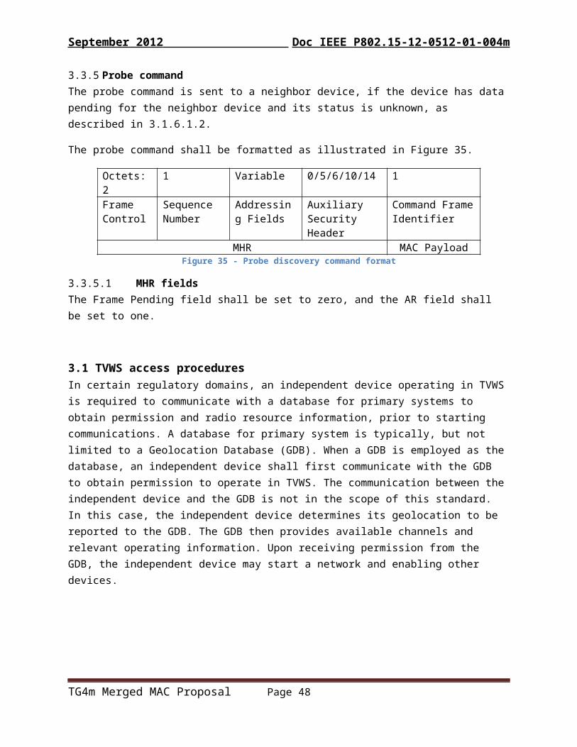
September 2012 Doc IEEE P802. 15-12-0512-01-004m
DBS. NumberOfDescendents PHY Channel ID See 8.1.2 Value to of the Number
of the Descendant field in the received DBS request: indicates the actual or expected number of descendant PAN coordinators. Set as zero if the PAN coordinator is not clear about how many descendants it will have.
SecurityLevel
As defined in Table 48KeyIdModeKeySourceKeyIndex
When the next higher layer of a parent PAN coordinator receives the MLME-DBS.indication primitive, the parent PAN coordinator determines whether to accept or reject the DBS allocation request using an algorithm outside the scope of this standard.
6.2.23.3 MLME-DBS.responseThe MLME-DBS.response primitive is used to initiate a response to an MLME-DBS.indication primitive.
The semantics of this primitive are:
MLME-DBS.response (CoordAddress,RequesterCoordAddr,DBSStartingSlot,DBSLength,ChannelNumber,ChannelPage,StartingChNum,EndingChNum,SecurityLevel,KeyIdMode,KeySource,KeyIndex
)The primitive parameters are defined in
Table 14: MLME-DBS.response Parameters
Name Type Valid range Description
TG4m Merged MAC Proposal Page 48
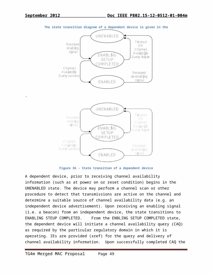
September 2012 Doc IEEE P802. 15-12-0512-01-004m
CoordAddress Device Shortaddress
0x0000–0xffff The short address of the Coordinator that sent TMCTP DBS Request
RequesterCoordAddr Device Shortaddress
0x0000–0xffff The short device address of the (original) source requester PAN coordinator.
DBSStartingSlot Integer See [xref] The first slot of the allocated DBS in the BOP
DBSLength Integer See [xref] The size, in BOP slots, of the allocated DBS.
ChannelNumber PHY Channel ID See 8.1.2 The channel number that the coordinator intends to use for all future communications
ChannelPage Integer See 8.1.2 The channel page that the coordinator intends to use for all future communications.
StartingChNum PHY Channel ID See 8.1.2 The lowest channel number, which is assigned by the parent PAN coordinator
EndingChNum PHY Channel ID See 8.1.2 The highest channel number, which is assigned by the parent PAN coordinator
SecurityLevel
As defined in Table 48KeyIdModeKeySourceKeyIndex
When the MLME of a parent PAN coordinator receives the MLME-DBS.response primitive, it generates a DBS response command, as described in 5.3.15, and attempts to send it to the child PAN coordinator requesting the allocation of a DBS and a channel.
6.2.23.4 MLME-DBS.confirmThe MLME-DBS.confirm primitive is used to inform the next higher layer of the initiating device whether its request for the allocation of a DBS and a channel was successful or unsuccessful.
The semantics of this primitive are:
MLME-DBS.confirm (RequesterCoordAddr,DBSStartingSlot,DBSLength,
TG4m Merged MAC Proposal Page 49

September 2012 Doc IEEE P802. 15-12-0512-01-004m
ChannelNumber,ChannelPage,StartingChNum,EndingChNum,status
)
The primitive parameters are defined in Table 15.
Table 15: MLME-DBS.confirm parameters
Name Type Valid range DescriptionRequesterCoordAddr
Integer 0x0000-0xffff The short device address of the (original) source requester PAN coordinator.
DBSStartingSlot Integer See [xref] The first slot of the allocated DBS in the BOP
ChannelNumber PHY Channel ID See 8.1.2 The channel number that the coordinator intends to use for all future communications
ChannelPage Integer See 8.1.2 The channel page that the coordinator intends to use for all future communications.
StartingfChNum PHY Channel ID See 8.1.2 The lowest channel number, which is assigned by the parent PAN coordinator
EndingChNum PHY Channel ID See 8.1.2 The highest channel number, which is assigned by the parent PAN coordinator
Status Enumeration SUCCESS, (TBD),NO_ACK,DENIED,UNAVAILABLE_KEY,UNSUPPORTED_SECURITY,INVALID_PARAMETER
The status of the attempt of the allocation of a DBS and a channel.
If the DBS allocation request was successful, then the status parameter will be set to SUCCESS. Otherwise, the status parameter will be set to indicate the type of failure.
6.2.24 Primitives for neighbor discoveryThese primitives are used for neighbor device discovery.
6.2.24.1 MLME-NBR.Request primitiveThe MLME-NBR.Request primitive prompts the device to discover neighbor devices.
The semantics of this primitive are:
TG4m Merged MAC Proposal Page 50

September 2012 Doc IEEE P802. 15-12-0512-01-004m
MLME-NBR.Request (CoordAddrMode,CoordPANId,CoordAddress)
The primitive parameters are defined in Table 16.
Table 16: MLME-NBR.Request Parameters
Name Type Valid range DescriptionCoordAddrMode Enumeration SHORT_ADDRESS,
EXTENDED_ADDRESSThe addressing mode of the coordinator that this device associated with.
CoordPANId Integer 0x0000 - 0xffff The identifier of the PAN that this device associated with.
CoordAddress Device address As specified by the CoordAddrMode parameter
the address of the coordinator that this device associated with
On receipt of the MLME-NBR.Request primitive, the MLME starts the neighbor discovery process as described in 5.1.6.7.1.
6.2.24.2 MLME-NBR.Confirm primitiveThe MLME-NBR.Confirm primitive reports results of neighbor discovery.
The semantics of this primitive are
MLME-NBR.Confirm (status
)
The primitive parameter is described in Table 17.
Table 17: MLME-NBR.Confirm parameters
Name Type Valid range DescriptionCoordAddrMode Enumeration SHORT_ADDRESS,
EXTENDED_ADDRESSThe addressing mode of the coordinator that this device associated with.
TG4m Merged MAC Proposal Page 51

September 2012 Doc IEEE P802. 15-12-0512-01-004m
The MLME-NBR.Confirm primitive is generated by MLME and issued to its next higher layer in response to an MLME-NBR.Request primitive.
6.3 MAC data service
6.3.12 MCPS-Data.requestInsert Insert the following new parameters at the end of the list in 6.3.1 (before the closing parenthesis):
UseRangingIE
Insert the following new rows at the end of Table 46:
Table 46 – MCPS-DATA.request parameters
Name Type Valid range DescriptionUseRangingIE Boolean TRUE, FALSE Set TRUE to indicate that a ranging
request IE should be included in the generated MPDU.
6.3.13 MCPS-DATA.confirmAdd new parameters
6.3.14 MCPS-DATA.indicationInsert the following new parameters at the end of the list in 6.3.3 (before the closing parenthesis):
PeriodicListeningIntervalPeriodicListeningDuration RendezvousTimeTransactionTimeUseRangingIE
Insert the following new rows at the end of Table 48:
[description of where the new parameters come from]
Table 48 - MCPS-DATA.indication parameters
Name Type Valid range DescriptionPeriodicListeningInterval Integer 0 to 16777215 Value of the Periodic listening interval
field of a received TVWSPS IE. PeriodicListeningDuration Integer 0 to 16777215 Value of the Periodic listening duration
field of a received TVWSPS IE.RendezvousTime Integer 0 to 16777215 Value of the Rendezvous time field of a
received TVWSPS IE.
TG4m Merged MAC Proposal Page 52

September 2012 Doc IEEE P802. 15-12-0512-01-004m
TransactionDuration Integer 0 to 65535 Value of the Transaction duration field of a received TVWSPS IE.
6.4 MAC constants and PIB attributesInsert the following rows to the end of Table 52:
Table 52 - MAC PIB attributes
Attribute Type Range Description DefaultmacTVWSPSListeningDuration Integer 0 -
16777215Time in milliseconds time between the start and the end of a periodic listening period when TVWS PS is enabled.
TBD
macTVWSPSListeningInterval Integer 0 - 16777215
Time in milliseconds between the start of a periodic listening duration to the start of the subsequent periodic listening duration when TVWS PS is enabled.
TBD
macTVWSPSPollingDuration Integer 0 - 16777215
Time in milliseconds that the initiating device repeats the polling operation when TVWSPS is enabled when TVWS PS is enabled.
TBD
macTVWSPSPollingInterval Integer 0 - 16777215
Time in milliseconds between transmissions of the MAC frames containing the TVWSPS IE during the polling phase when TVWS PS is enabled.
TBD
macTVWSPSRendezvousTime Integer 0 - 16777215
The Rendezvous time field is the time in milliseconds between the end of the acknowledgement frame sent by a responding device or received by an initiating device, and the start of the data transaction between the two devices when TVWS PS is enabled.
TBD
macTVWSPSTransDuration Integer 0 - 65535 Time in milliseconds needed complete the transaction between the initiating and responding devices when TVWS PS is enabled.
TBD
TG4m Merged MAC Proposal Page 53
September 2012 Doc IEEE P802. 15-12-0512-01-004m
macTVWSPSenable Boolean TRUE, FALSE
Indicates that TVWS PS is enabled.
FALSE
TG4m Merged MAC Proposal Page 54

September 2012 Doc IEEE P802. 15-12-0512-01-004m
ANNEX Q Considerations for operation in TVWS [provide overview and specific information on how the MAC features provided are used to enable operation in the TVWS bands under known regulations at the time of publication with appropriate caveats about regulatory changes]
Q.1. IntroductionOverview of the TVWS operational differences
Q.2. Enabling access to TVWS channelsDescription of typical requirements for enabling access and how this can be achieved with this standard.
Q.3. Considerations in non-beacon PANsDescription of how 4TV peer-to-peer networks might work.
Q.4. Band sharingDescription of the requirements for vacating the band when told to defer to protected users, and how the dynamic band switching can be achieved using the PHY parameter change mechanisms.
Q.5. Other
TG4m Merged MAC Proposal Page 55