Embed Size (px)
Citation preview

Direct Digital Control SystemsTECHNICAL GUIDE TG 15910
1. Coordination Issues:
1.1 Coordinate power supply (i.e. voltage, amps, locations, etc.) for the mechanical equipment, field control devices and DDC system with the Electrical Consultant.
1.2 Coordinate location of the building work station server with the building occupant(s) and/or maintenance personnel responsible for controlling, maintaining and repairing the HVAC equipment and controls.
1.3 Coordinate location of particular room thermostats between the building occupant(s) and designer especially if an existing thermostat is to be replaced, there are repeated complaints about temperature conditions in the controlled zone and existing location not placed in accordance with recommended industry practices.
2. Design Issues: Design drawings and specifications shall provide sufficient information on floor plans, sequence of operations, schematic control diagrams, details, descriptions, points list, etc. such that the Direct Digital Controls subcontractor has enough information to develop the controls shop drawings to make the HVAC system operate as intended by the designer.
3. Design Drawing Notes:
3.1 The Consultant Shall Create a “Points List” on the Drawings and Coordinate the Points List with Each Affected Mechanical Equipment and components requiring connection to the Direct Digital Control System.
3.2 All mechanical equipment and other associated field installed devices (static pressure sensor, temperatures sensors, 2-way valves, damper motor, etc.) requiring connection to the Direct Digital Control System and electrical power shall be located on the drawings. Show location of the DDC building work station server and proposed location of major control panels/modules (DDC subcontractor shop drawings should show more specific details of the control system components, cabling, wiring diagrams, etc.).
4. Standard Drawings: (Not Used)
5. Specification Notes:
5.1 This guide specification covers the requirements for direct digital control (DDC) of heating, ventilating, and air conditioning (HVAC) systems. This control system shall provide the capability to monitor and control all HVAC control functions. Analog and digital (binary, on/off, open/close) control signals are input to microprocessor based digital controllers. The digital controllers perform the control logic and output analog and digital signals to the HVAC equipment.
5.2 The control system shall consist of a high-speed, peer-to-peer network of DDC controllers and a web based operator interface. Operators shall be able to perform all normal operator functions through the web browser interface.
Provide DDC software installation for the building work station server with RAID 1 (mirroring) drives. Duplicate drives provides backup capability in case of problems with one of the drives.
Laptop computer, notebook computer or some type of equivalent portable device shall be provided to the operator to allow web based access into the DDC control system. The
DESIGN CONSULTANT CRITERIAV12.02
TG 15910 - 1

operator shall be able to perform all normal operator functions through the web browser interface similar to the access provided by a workstation.
5.3 For CENTRAL CHILLER SYSTEMS, the following shall be added to the specification section that covers the chiller (e.g. SECTION 15xxx CENTRAL REFRIGERATION EQUIPMENT FOR AIR CONDITIONING):
[CHILLER TRANSLATOR/BACnet:
As part of the Chiller Control package provided with the Chiller by the Chiller Manufacturer, provide a communications system that will allow a BACnet-based Direct Digital Control (DDC) system to access each Chiller’s Microprocessor/Control Panel’s vast array of point information (such as pressures, temperatures, status, runtimes, suction, Amps, KW, and others), without installing any duplicate sensors.
The BACnet Chiller translator will communicate to the DDC system bi-directionally, utilizing standard ASHRAE BACnet Protocol, and will allow full Monitoring and Reset control of the Chillers by the BACnet DDC system.
The Chiller Manufacturer is to provide all as necessary to accomplish this Chiller interface, such as complete list of all available Chiller Points, all BACnet Protocol Implementation Conformance Statements (PICS) files, any necessary Software, all necessary Passwords, Labor as needed, and all interface Hardware as necessary for complete and operational connection to the BACnet DDC System.]
5.4 Delete hardware and software items that are not used for the specific project.
6. Guide Specification:
6.1 SECTION 15910 DIRECT DIGITAL CONTROL SYSTEMS
SPECIFIER’S NOTE: Blue colored italicized text is used for notes to the specifier and should be completely deleted from the final text. Where [Red colored italicized text in parentheses] is shown in this specification section, insert wording, numbers, etc. as appropriate and delete parentheses. Where <Red colored text in brackets> is shown, a choice is indicated. Make the appropriate choice and delete the brackets. Maintain footer notation with the current version used (e.g. TG12320 v02.02). Section titles with numbers and coordinated referencing between various Sections of this Project’s specifications is the responsibility of the specifier.
DESIGN CONSULTANT CRITERIAV12.02
TG 15910 - 2

SECTION 15910 DIRECT DIGITAL CONTROL SYSTEMS
PART 1 - GENERAL 1.01 SUMMARY
A. This Section includes control equipment for HVAC systems and components, including control components for terminal heating and cooling units not supplied with factory-wired controls.
B. The control system shall consist of a high-speed, peer-to-peer network of DDC controllers and a web based operator interface. Depict each mechanical system and building floor plan by a point-and-click graphic. A web server with a network interface card shall gather data from this system and generate web pages accessible through a conventional web browser on each PC connected to the network. Operators shall be able to perform all normal operator functions through the web browser interface.
C. The Direct Digital Control (DDC) system must be based on the native BACnet protocol.
Provide all necessary hardware and software to provide web based access and control via a Microsoft Windows operating system and Internet Explorer browser.
SPECIFIER’S NOTE: If there is an existing DDC control system and workstation server within the building or facility, the name of the controls equipment manufacturer and location of the workstation server shall be shown on the drawings. Designer shall provide sufficient information on the drawings and specifications such that any bidder can determine how to interface with the existing DDC system and estimate the cost to do the work for any new additional DDC controls. Operators shall have the capability to perform same operator functions through the web browser with the existing and new additional DDC controls.
1.02 DEFINITIONS A. DDC: Direct digital control. B. I/O: Input/output. C. LAN: Local Area Network. D. MS/TP: Master slave/token passing. E. PC: Personal computer. F. PID: Proportional plus integral plus derivative. G. RTD: Resistance temperature detector.
1.03 SYSTEM PERFORMANCE
A. Comply with the following performance requirements: 1. Graphic Display: Display graphic with minimum 20 dynamic points with current data
within 10 seconds. 2. Graphic Refresh: Update graphic with minimum 20 dynamic points with current data
within 8 seconds. 3. Object Command: Reaction time of less than two seconds between operator
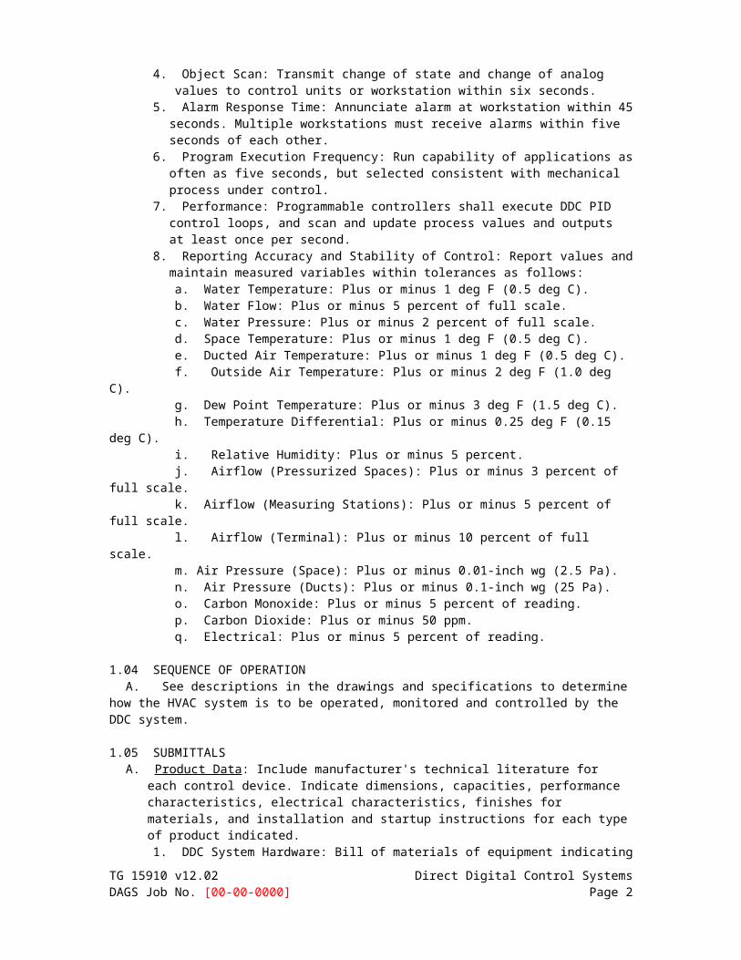
command of a binary object and device reaction. 4. Object Scan: Transmit change of state and change of analog values to control units or
workstation within six seconds. 5. Alarm Response Time: Annunciate alarm at workstation within 45 seconds. Multiple
workstations must receive alarms within five seconds of each other. 6. Program Execution Frequency: Run capability of applications as often as five
seconds, but selected consistent with mechanical process under control. 7. Performance: Programmable controllers shall execute DDC PID control loops, and
scan and update process values and outputs at least once per second. 8. Reporting Accuracy and Stability of Control: Report values and maintain measured
variables within tolerances as follows: a. Water Temperature: Plus or minus 1 deg F (0.5 deg C). b. Water Flow: Plus or minus 5 percent of full scale. c. Water Pressure: Plus or minus 2 percent of full scale.
TG 15910 v12.02 Direct Digital Control SystemsDAGS Job No. [00-00-0000] Page 1

d. Space Temperature: Plus or minus 1 deg F (0.5 deg C). e. Ducted Air Temperature: Plus or minus 1 deg F (0.5 deg C). f. Outside Air Temperature: Plus or minus 2 deg F (1.0 deg C). g. Dew Point Temperature: Plus or minus 3 deg F (1.5 deg C). h. Temperature Differential: Plus or minus 0.25 deg F (0.15 deg C). i. Relative Humidity: Plus or minus 5 percent. j. Airflow (Pressurized Spaces): Plus or minus 3 percent of full scale. k. Airflow (Measuring Stations): Plus or minus 5 percent of full scale. l. Airflow (Terminal): Plus or minus 10 percent of full scale. m. Air Pressure (Space): Plus or minus 0.01-inch wg (2.5 Pa). n. Air Pressure (Ducts): Plus or minus 0.1-inch wg (25 Pa). o. Carbon Monoxide: Plus or minus 5 percent of reading. p. Carbon Dioxide: Plus or minus 50 ppm. q. Electrical: Plus or minus 5 percent of reading.
1.04 SEQUENCE OF OPERATION
A. See descriptions in the drawings and specifications to determine how the HVAC system is to be operated, monitored and controlled by the DDC system.
1.05 SUBMITTALS A. Product Data: Include manufacturer's technical literature for each control device. Indicate
dimensions, capacities, performance characteristics, electrical characteristics, finishes for materials, and installation and startup instructions for each type of product indicated. 1. DDC System Hardware: Bill of materials of equipment indicating quantity,
manufacturer, and model number. Include technical data for operator workstation equipment, interface equipment, control units, transducers/transmitters, sensors, actuators, valves, relays/switches, control panels, and operator interface equipment.
2. Control System Software: Include technical data for operating system software, operator interface, color graphics, and other third-party applications. Operator interface shall be graphically based and shall include at least one graphic per piece of equipment or occupied zone.
3. Controlled Systems: Instrumentation list with element name, type of device, manufacturer, model number, and product data. Include written description of sequence of operation including schematic diagram.
B. Shop Drawings: Detail equipment assemblies and indicate dimensions, weights, loads,
required clearances, method of field assembly, components, and location and size of each field connection. 1. Bill of materials of equipment indicating quantity, manufacturer, and model number. 2. Schematic flow diagrams showing fans, pumps, coils, dampers, valves, and control
devices. 3. Wiring Diagrams: Power, signal, and control wiring. 4. Details of control panel faces, including controls, instruments, and labeling. 5. Written description of sequence of operation. 6. Schedule of dampers including size, leakage, and flow characteristics. 7. Schedule of valves including flow characteristics. 8. DDC System Hardware:
a. Wiring diagrams for control units with termination numbers. b. Schematic diagrams and floor plans for field sensors and control hardware. c. Schematic diagrams for control, communication, and power wiring, showing trunk
data conductors and wiring between operator workstation andcontrol unit locations. Description of the various types of wire or cables with the designated function shall be provided.
9. Control System Software: List of color graphics indicating monitored systems, data (connected and calculated) point addresses, output schedule, and operator notations.
10. Controlled Systems: a. Schematic diagrams of each controlled system with control points labeled and
control elements graphically shown, with wiring. TG 15910 v12.02 Direct Digital Control SystemsDAGS Job No. [00-00-0000] Page 2
b. Scaled drawings showing mounting, routing, and wiring of elements including bases and special construction.
c. Written description of sequence of operation including schematic diagram. d. Points list.
1.06 DATA COMMUNICATION PROTOCOL CERTIFICATES:
A. Certify that each proposed DDC system component complies with ASHRAE 135.
1.07 CLOSEOUT SUBMITTALS A. Operation and Maintenance Manual/Documentation: This manual or documentation is to
intended to provide a complete description of the HVAC system and DDC control system. The following information shall be provided in a 3-ring binder(s) unless mentioned otherwise:1. Description of HVAC System: Provide a general description of the HVAC system and
major equipment that it is comprised of. Provide a list of installed equipment with the manufacturer’s name and model/part number. The listed items shall be labeled such that it can be referenced to a particular piece of equipment on the as-built drawing (example: AHU-1, CHWP-2, SF-3, Cooling Tower#3, 2-way chilled water valve for AHU-1, etc.). Information for the HVAC equipment should be furnished by catalog data or other submittals in other Division 15 specification sections.
2. Description of DDC Control System: Provide a general description of the DDC control system with list of parts with name of manufacturer and model/part number unless every item in the DDC as-built drawings already contain this information. Refer to DDC controls as-built drawings.
3. Control equipment catalog cuts providing description of equipment specifications (if applicable), software specifications, power and communication signal information, etc.
4. Maintenance instructions and lists of spare parts for each type of control device and compressed-air station components (if applicable).
5. Printout of pre-programmed operating parameters such as equipment start-stop times, leaving chilled water temperature set point, room air temperature set point, static pressure setting for each VFD Air Handler, alarm set points, etc.
6. Service Organization: Qualified service organization list that shall include the names and telephone numbers of an organization(s) located in the [State of Hawaii] qualified to troubleshoot and service the DDC control system.
B. Software and Firmware Operational Documentation: Include the following:
1. DDC Software operating and upgrade manuals. 2. DDC Program Software Backup: On a magnetic media or compact disc, complete with
data files. 3. Device address list. 4. Listing of all software applications required for operation of and accessing into the
DDC control system. 5. Software license required by and installed for DDC workstations and control systems.
C. As-Built Drawings: A complete set of as-built drawings for the HVAC system is to be a combination of as-built design drawings and as-built control drawings whichshould show locations of all HVAC equipment and field installed accessories, how the systems are intended to operate and DDC control shop drawings which should show the manufacturer of equipment, network diagrams, communication protocols, all components, list of materials, etc.
1.08 QUALITY ASSURANCE
A. Installer Qualifications: DDC control system manufacturer's authorized representative who is trained and approved for installation of system components is required for this project.
B. Electrical Components, Devices, and Accessories: Listed and labeled as defined in NFPA
70, Article 100, by a testing agency acceptable to authorities having jurisdiction, and marked for intended use.
TG 15910 v12.02 Direct Digital Control SystemsDAGS Job No. [00-00-0000] Page 3

C. Comply with ASHRAE 135 for DDC system components.
D. The DDC Contractor shall have a minimum of 5 years experience with the complete installation of the DDC control system they are going to install on this project. The DDC Contractor shall provide a list of comparably sized and/or technically complex control systems installed for 3 other buildings or facilities which are still in operation at the time for bidding on this project.
1.09 DELIVERY, STORAGE, AND HANDLING
A. Factory-Mounted Components: Where control devices specified in this Section are indicated to be factory mounted on equipment, arrange for shipping of control devices to equipment manufacturer.
B. System Software: Update to latest version of software at Project completion.
1.10 COORDINATION A. Coordinate location of thermostats, humidistats, and other exposed control sensors with
plans and room details before installation.
B. Coordinate electrical power supply for all mechanical equipment, motors, field devices and DDC control components with the Electrical Consultant.
C. Coordinate location of the building work station server for the DDC control system with the
user and designer. Show the location of this equipment on the drawings.
1.11 WARRANTYA. Warranty labor and materials for specified control system free from defects for a period of I
year after final acceptance. Control systems failure during warranty period shall be adjusted, repaired or replaced at no additional cost or reduction in service.
B. Work shall have a single warranty date even if the building or facility receives beneficial use due to early system start-up but without final completion, inspection and acceptance.
C. The DDC Contractor shall have a local facility in the [State of Hawaii]. Emergency service shall be available on a 24 hour/7 day a week basis.
SPECIFIER’S NOTE: Since technology, particularly for computer or communication devices, changes rapidly, the designer should determine if some of the characteristics shown in this guide specification should be updated to more current standards.
PART 2 - PRODUCTS 2.01 CONTROL SYSTEM
A. Control system shall consist of sensors, indicators, actuators, final control elements, interface equipment, other apparatus, accessories, and software connected to distributed controllers operating in multi-user, multitasking environment on token-passing network and programmed to control mechanical systems. An operator workstation permits interface with the network via dynamic color graphics with each mechanical system, building floor plan, and control device depicted by point-and-click graphics.
2.02 DDC EQUIPMENT A. Operator Workstation: [One] [Two] <Insert number> PC-based microcomputer(s) with
minimum configuration as follows: 1. Motherboard: With 8 integrated USB 2.0 ports, integrated Intel Pro 10/100 (Ethernet),
integrated audio, bios, and hardware monitoring. 2. Processor: [Intel or AMD with minimum 2 Ghz clock speed].3. Random-Access Memory: [2 GB minimum].
TG 15910 v12.02 Direct Digital Control SystemsDAGS Job No. [00-00-0000] Page 4

4. Graphics: Video adapter, minimum [1600 x 1200] pixels, [64]-MB video memory, with TV out.
5. Monitor: [ 17 inches (430 mm) ], LCD color. 6. Keyboard: QWERTY, 105 keys in ergonomic shape. 7. Hard-Disk Drive: [200 GB] RAID 1 (mirroring). 8. CD/DVD Read/Write Drive: [16x CD-RW/DVD].
9. Mouse: Three button, optical, scroll. 10. Uninterruptible Power Supply: [2] kVa. 11. Operating System: [Microsoft Windows XP Professional, Vista or Windows 7] with
high-speed Internet access. a. ASHRAE 135 Compliance: Workstation shall use ASHRAE 135 protocol and
communicate using ISO 8802-3 (Ethernet) datalink/physical layer protocol. 12. Printer: Black-and-white, laser-jet type as follows:
a. Print Head: [1200 x 1200] dpi resolution. b. Paper Handling: Minimum of [250] sheet trays. c. Print Speed: Minimum of [120] characters per second.
13. Printer: Color, ink-jet type as follows: a. Print Head: [4800 x 1200] dpi optimized color resolution. b. Paper Handling: Minimum of [100] sheets. c. Print Speed: Minimum of [17] ppm in black and [12] ppm in color.
14. Application Software: a. I/O capability from operator station. b. System security for each operator via software password and access levels. c. Automatic system diagnostics; monitor system and report failures. d. Database creation and support. e. Automatic and manual database save and restore. f. Dynamic color graphic displays with up to [10] screen displays at once. g. Custom graphics generation and graphics library of HVAC equipment and
symbols. h. Alarm processing, messages, and reactions. i. Trend logs retrievable in spreadsheets and database programs. j. Alarm and event processing. k. Object and property status and control. l. Automatic restart of field equipment on restoration of power.
m. Data collection, reports, and logs. Include standard reports for the following: 1) Current values of all objects. 2) Current alarm summary. 3) Disabled objects. 4) Alarm lockout objects. 5) Logs.
n. Energy Calculations and Utility Recorded Data: Flow rates, temperatures, etc. measurements necessary to calculate cumulative average energy consumption can be set to record data at pre-determined intervals such as every 15 minutes, 30 minutes, 60 minutes, etc. for “X” number of days and re-settable on a recurring basis.
1) Averaged chilled water thermal energy consumption in BTU/HR using chilled water supply and return temperatures and water flow rates.
2) Record electrical energy in KWH and electrical demand in KW via electrical submeter (non HECO).
3) Potable water consumption or water deduct meters for irrigation sewer charges can be recorded via approved Board of Water Supply meters.
o. Other custom report development. p. Utility and weather reports. q. Workstation application editors for controllers and schedules. r. Maintenance management.s. Time programs: Provide program to automatically adjust for leap years and make
daylight savings time and standard time adjustments. 15. Custom Application Software:
TG 15910 v12.02 Direct Digital Control SystemsDAGS Job No. [00-00-0000] Page 5

a. English language oriented. b. Full-screen character editor/programming environment. c. Allow development of independently executing program modules with
debugging/simulation capability. d. Support conditional statements. e. Support floating-point arithmetic with mathematic functions. f. Contains predefined time variables.
B. Control Units: Modular, comprising processor board with programmable, nonvolatile,
random-access memory; local operator access and display panel; integral interface equipment; and backup power source. 1. Units monitor or control each I/O point; process information; execute commands from
other control units, devices, and operator stations; and download from or upload to operator workstation or diagnostic terminal unit.
2. Stand-alone mode control functions operate regardless of network status. Functions include the following: a. Global communications. b. Discrete/digital, analog, and pulse I/O. c. Monitoring, controlling, or addressing data points. d. Software applications, scheduling, and alarm processing. e. Testing and developing control algorithms without disrupting field hardware and
controlled environment. 3. Standard Application Programs:
a. Electric Control Programs: Demand limiting, duty cycling, automatic time scheduling, start/stop time optimization, night setback/setup, on-off control with differential sequencing, staggered start, antishort cycling, PID control, DDC with fine tuning, and trend logging.
b. HVAC Control Programs: Optimal run time, supply-air reset, and enthalpy switchover.
c. Chiller Control Programs: Control function of condenser-water reset, chilled-water reset, and equipment sequencing.
d. Programming Application Features: Include trend point; alarm processing and messaging; weekly, monthly, and annual scheduling; energy calculations; run-time totalization; and security access.
e. Remote communications. f. Maintenance management.
g. Units of Measure: Inch-pound and SI (metric). 4. Local operator interface provides for download from or upload to operator workstation
or diagnostic terminal unit. 5. ASHRAE 135 Compliance: Control units shall use ASHRAE 135 protocol and
communicate using ISO 8802-3 (Ethernet) datalink/physical layer protocol.
C. Local Control Units: Modular, comprising processor board with electronically programmable, nonvolatile, read-only memory; and backup power source. 1. Units monitor or control each I/O point, process information, and download from or
upload to operator workstation or diagnostic terminal unit. 2. Stand-alone mode control functions operate regardless of network status. Functions
include the following: a. Global communications. b. Discrete/digital, analog, and pulse I/O. c. Monitoring, controlling, or addressing data points.
3. Local operator interface provides for download from or upload to operator workstation or diagnostic terminal unit.
4. ASHRAE 135 Compliance: Control units shall use ASHRAE 135 protocol and communicate using ISO 8802-3 (Ethernet) datalink/physical layer protocol.
D. I/O Interface: Hardwired inputs and outputs may tie into system through controllers. Protect
points so that shorting will cause no damage to controllers. TG 15910 v12.02 Direct Digital Control SystemsDAGS Job No. [00-00-0000] Page 6

1. Binary Inputs: Allow monitoring of on-off signals without external power. 2. Pulse Accumulation Inputs: Accept up to 10 pulses per second. 3. Analog Inputs: Allow monitoring of low-voltage (0- to 10-V dc), current (4 to 20 mA), or
resistance signals. 4. Binary Outputs: Provide on-off or pulsed low-voltage signal, selectable for normally
open or normally closed operation[ with three-position (on-off-auto) override switches and status lights].
5. Analog Outputs: Provide modulating signal, either low voltage (0- to 10-V dc) or current (4 to 20 mA) [ with status lights, two-position (auto-manual) switch, and manually adjustable potentiometer].
6. Tri-State Outputs: Provide two coordinated binary outputs for control of three-point, floating-type electronic actuators.
7. Universal I/Os: Provide software selectable binary or analog outputs.
E. Power Supplies: Transformers with Class 2 current-limiting type or overcurrent protection; limit connected loads to 80 percent of rated capacity. DC power supply shall match output current and voltage requirements and be full-wave rectifier type with the following: 1. Output ripple of 5.0 mV maximum peak to peak. 2. Combined 1 percent line and load regulation with 100-mic.sec. response time for 50
percent load changes. 3. Built-in overvoltage and overcurrent protection and be able to withstand 150 percent
overload for at least 3 seconds without failure.
F. Power Line Filtering: Internal or external transient voltage and surge suppression for workstations or controllers with the following: 1. Minimum dielectric strength of 1000 V. 2. Maximum response time of 10 nanoseconds. 3. Minimum transverse-mode noise attenuation of 65 dB. 4. Minimum common-mode noise attenuation of 150 dB at 40 to 100 Hz.
2.03 UNITARY CONTROLLERS
A. Unitized, capable of stand-alone operation with sufficient memory to support its operating system, database, and programming requirements, and with sufficient I/O capacity for the application. 1. Configuration: Local keypad and display; diagnostic LEDs for power, communication,
and processor; wiring termination to terminal strip or card connected with ribbon cable; memory with bios; and [72] -hour battery backup.
2. Operating System: Manage I/O communication to allow distributed controllers to share real and virtual object information and allow central monitoring and alarms. [Perform scheduling with real-time clock. ]Perform automatic system diagnostics; monitor system and report failures.
3. ASHRAE 135 Compliance: Communicate using read (execute and initiate) and write (execute and initiate) property services defined in ASHRAE 135. Reside on network using MS/TP datalink/physical layer protocol and have service communication port for connection to diagnostic terminal unit.
4. Enclosure: Dustproof rated for operation at 32 to 120 deg F (0 to 50 deg C) . 5. Enclosure: Waterproof rated for operation at 40 to 150 deg F (5 to 65 deg C).
2.04 ALARM PANELS
A. Unitized cabinet with suitable brackets for wall or floor mounting. Fabricate of 0.06-inch- (1.5-mm-) thick, furniture-quality steel or extruded-aluminum alloy, totally enclosed, with hinged doors and keyed lock and with manufacturer's standard shop-painted finish. [Provide common keying for all panels.]
B. Indicating light for each alarm point, single horn, acknowledge switch, and test switch,
mounted on hinged cover. 1. Alarm Condition: Indicating light flashes and horn sounds. 2. Acknowledge Switch: Horn is silent and indicating light is steady.
TG 15910 v12.02 Direct Digital Control SystemsDAGS Job No. [00-00-0000] Page 7

3. Second Alarm: Horn sounds and indicating light is steady. 4. Alarm Condition Cleared: System is reset and indicating light is extinguished. 5. Contacts in alarm panel allow remote monitoring by independent alarm company.
2.05 ANALOG CONTROLLERS
A. Step Controllers: 6- or 10-stage type, with heavy-duty switching rated to handle loads and operated by electric motor.
B. Electric, Outdoor-Reset Controllers: Remote-bulb or bimetal rod-and-tube type,
proportioning action with adjustable throttling range, adjustable set point, scale range minus 10 to plus 70 deg F (minus 23 to plus 21 deg C) , and single- or double-pole contacts.
C. Electronic Controllers: Wheatstone-bridge-amplifier type, in steel enclosure with provision
for remote-resistance readjustment. Identify adjustments on controllers, including proportional band and authority. 1. Single controllers can be integral with control motor if provided with accessible control
readjustment potentiometer.
D. Fan-Speed Controllers: Solid-state model providing field-adjustable proportional control of motor speed from maximum to minimum of 55 percent and on-off action below minimum fan speed. Controller shall briefly apply full voltage, when motor is started, to rapidly bring motor up to minimum speed. Equip with filtered circuit to eliminate radio interference.
E. Receiver Controllers: Single- or multiple-input models with control-point adjustment, direct or reverse acting with mechanical set-point adjustment with locking device, proportional band adjustment, authority adjustment, and proportional control mode. 1. Remote-control-point adjustment shall be plus or minus 20 percent of sensor span,
input signal of 3 to 13 psig (21 to 90 kPa) . 2. Proportional band shall extend from 2 to 20 percent for 5 psig (35 kPa).
3. Authority shall be 20 to 200 percent. 4. Air-supply pressure of 18 psig (124 kPa) , input signal of 3 to 15 psig (21 to 103 kPa) ,
and output signal of zero to supply pressure. 5. Gages: [ 3-1/2 inches (89 mm) ] in diameter, 2.5 percent wide-scale accuracy, and
range to match transmitter input or output pressure. 2.06 TIME CLOCKS
A. Seven-day, programming-switch timer with synchronous-timing motor and seven-day dial; continuously charged, nickel-cadmium-battery-driven, eight-hour, power-failure carryover; multiple-switch trippers; minimum of two and maximum of eight signals per day with two normally open and two normally closed output contacts.
B. Solid-state, programmable time control with [4] separate programs each with up to 100 on-off operations; 1-second resolution; lithium battery backup; keyboard interface and manual override; individual on-off-auto switches for each program; 365-day calendar with 20 programmable holidays; choice of fail-safe operation for each program; system fault alarm; and communications package allowing networking of time controls and programming from PC.
2.07 ELECTRONIC SENSORS A. Description: Vibration and corrosion resistant; for wall, immersion, or duct mounting as
required.
B. Thermistor Temperature Sensors and Transmitters: 1. Accuracy: Plus or minus [ 0.5 deg F (0.3 deg C) ] at calibration point. 2. Wire: Twisted, shielded-pair cable. 3. Insertion Elements in Ducts: Single point, [ 8 inches (200 mm) ] long; use where not
affected by temperature stratification or where ducts are smaller than 9 sq. ft. (0.84 sq. TG 15910 v12.02 Direct Digital Control SystemsDAGS Job No. [00-00-0000] Page 8

m) . 4. Averaging Elements in Ducts: [ 36 inches (915 mm) long, flexible]; use where prone to
temperature stratification or where ducts are larger than 10 sq. ft. (1 sq. m) . 5. Insertion Elements for Liquids: Brass or stainless-steel socket with minimum insertion
length of 2-1/2 inches (64 mm) . 6. Room Sensor Cover Construction: Manufacturer's standard locking covers.
a. Set-Point Adjustment: ,<Concealed> <Exposed>. b. Set-Point Indication: <Concealed> <Keyed> <Exposed>. c. Thermometer: <Concealed> <Exposed> <Red-reading glass> <Spiral bimetal>. d. Color: [Insert color from manufacturer's full range.] e. Orientation: [Vertical] [Horizontal].
7. Outside-Air Sensors: Watertight inlet fitting, shielded from direct sunlight. 8. Room Security Sensors: Stainless-steel cover plate with insulated back and security
screws.
C. RTDs and Transmitters: 1. Accuracy: Plus or minus 0.2 percent at calibration point. 2. Wire: Twisted, shielded-pair cable.3. Insertion Elements in Ducts: Single point, [ 8 inches (200 mm) ] long; use where not
affected by temperature stratification or where ducts are smaller than 9 sq. ft. (0.84 sq. m) .
4. Averaging Elements in Ducts: [ 18 inches (460 mm) long, rigid]; use where prone to temperature stratification or where ducts are larger than 9 sq. ft. (0.84 sq. m) ; length as required.
5. Insertion Elements for Liquids: Brass socket with minimum insertion length of 2-1/2 inches (64 mm) .
6. Room Sensor Cover Construction: Manufacturer's standard locking covers. a. Set-Point Adjustment: <Concealed> <Exposed>.
b. Set-Point Indication: <Concealed> <Keyed> <Exposed>. c. Thermometer: <Concealed> <Exposed> <Red-reading glass> <Spiral bimetal>. d. Color: <Insert color from manufacturer's full range.>
e. Orientation: <Vertical> <Horizontal>. 7. Outside-Air Sensors: Watertight inlet fitting, shielded from direct sunlight. 8. Room Security Sensors: Stainless-steel cover plate with insulated back and security
screws.
D. Humidity Sensors: Bulk polymer sensor element. 1. Accuracy: [2] percent full range with linear output. 2. Room Sensor Range: 20 to 80 percent relative humidity. 3. Room Sensor Cover Construction: Manufacturer's standard locking covers.
a. Set-Point Adjustment: <Concealed> <Exposed>. b. Set-Point Indication: <Concealed> <Keyed> <Exposed>. c. Thermometer: <Concealed> <Exposed> <Red-reading glass> <Spiral bimetal>. d. Color: [Insert color from manufacturer's full range.] e. Orientation: <Vertical> <Horizontal>.
4. Duct Sensor: 20 to 80 percent relative humidity range with element guard and mounting plate.
5. Outside-Air Sensor: 20 to 80 percent relative humidity range with mounting enclosure, suitable for operation at outdoor temperatures of [ 32 to 120 deg F (0 to 50 deg C) ].
6. Duct and Sensors: With element guard and mounting plate, range of 0 to 100 percent relative humidity.
E. Pressure Transmitters/Transducers:
1. Static-Pressure Transmitter: Nondirectional sensor with suitable range for expected input, and temperature compensated. a. Accuracy: 2 percent of full scale with repeatability of 0.5 percent. b. Output: 4 to 20 mA. c. Building Static-Pressure Range: 0- to 0.25-inch wg (0 to 62 Pa).
TG 15910 v12.02 Direct Digital Control SystemsDAGS Job No. [00-00-0000] Page 9

d. Duct Static-Pressure Range: 0- to 5-inch wg (0 to 1240 Pa) . 2. Water Pressure Transducers: Stainless-steel diaphragm construction, suitable for
service; minimum 150-psig (1034-kPa) operating pressure; linear output 4 to 20 mA. 3. Water Differential-Pressure Transducers: Stainless-steel diaphragm construction,
suitable for service; minimum 150-psig (1034-kPa) operating pressure and tested to 300-psig (2070-kPa) ; linear output 4 to 20 mA.
4. Differential-Pressure Switch (Air or Water): Snap acting, with pilot-duty rating and with suitable scale range and differential.
5. Pressure Transmitters: Direct acting for gas, liquid, or steam service; range suitable for system; linear output 4 to 20 mA.
F. Room sensor accessories include the following:
1. Insulating Bases: For sensors located on exterior walls. 2. Guards: [Locking, solid metal, ventilated]. 3. Adjusting Key: As required for calibration and cover screws.
2.08 PNEUMATIC SENSORS A. Pneumatic Transmitters: Vibration and corrosion resistant.
1. Space-Temperature Sensors: Linear-output type, 50 to 100 deg F (10 to 38 deg C) range, with blank locking covers matching room thermostats.
2. Room Return-Air Temperature Sensors: Linear-output type with bimetal sensing element and corrosion-proof construction, 50 to 100 deg F (10 to 38 deg C)
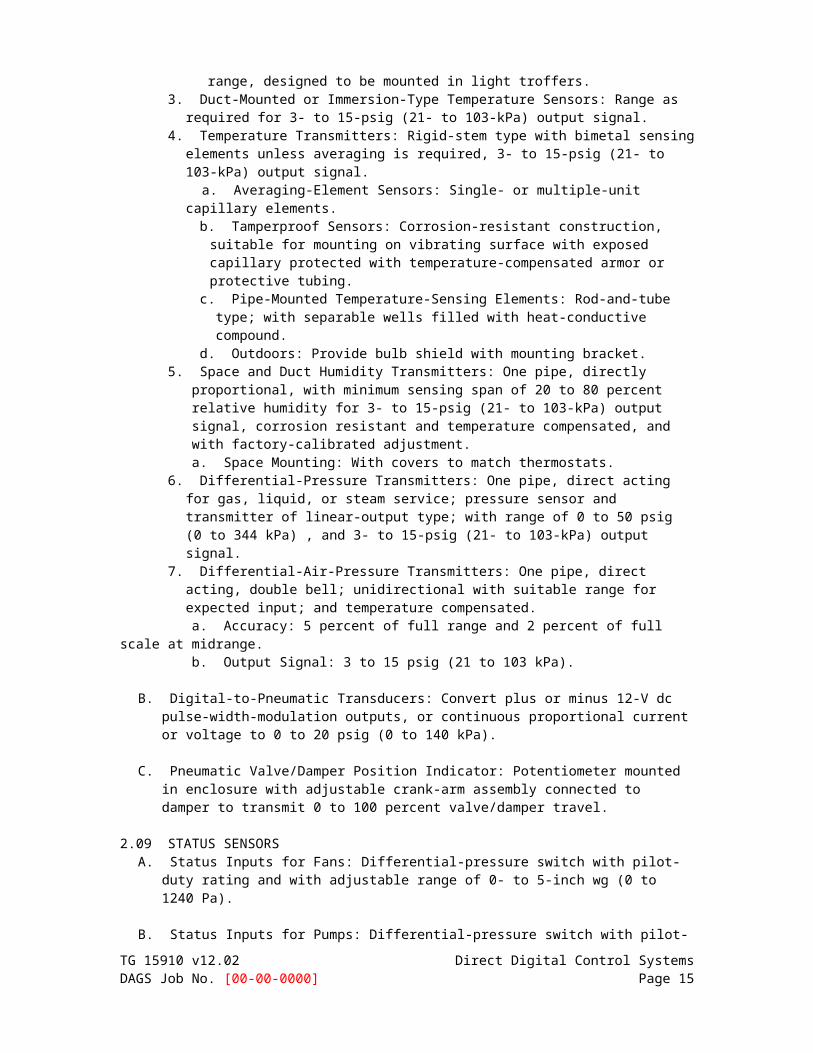
range, designed to be mounted in light troffers. 3. Duct-Mounted or Immersion-Type Temperature Sensors: Range as required for 3- to
15-psig (21- to 103-kPa) output signal. 4. Temperature Transmitters: Rigid-stem type with bimetal sensing elements unless
averaging is required, 3- to 15-psig (21- to 103-kPa) output signal. a. Averaging-Element Sensors: Single- or multiple-unit capillary elements.
b. Tamperproof Sensors: Corrosion-resistant construction, suitable for mounting on vibrating surface with exposed capillary protected with temperature-compensated armor or protective tubing.
c. Pipe-Mounted Temperature-Sensing Elements: Rod-and-tube type; with separable wells filled with heat-conductive compound.
d. Outdoors: Provide bulb shield with mounting bracket. 5. Space and Duct Humidity Transmitters: One pipe, directly proportional, with minimum
sensing span of 20 to 80 percent relative humidity for 3- to 15-psig (21- to 103-kPa) output signal, corrosion resistant and temperature compensated, and with factory-calibrated adjustment. a. Space Mounting: With covers to match thermostats.
6. Differential-Pressure Transmitters: One pipe, direct acting for gas, liquid, or steam service; pressure sensor and transmitter of linear-output type; with range of 0 to 50 psig (0 to 344 kPa) , and 3- to 15-psig (21- to 103-kPa) output signal.
7. Differential-Air-Pressure Transmitters: One pipe, direct acting, double bell; unidirectional with suitable range for expected input; and temperature compensated. a. Accuracy: 5 percent of full range and 2 percent of full scale at midrange. b. Output Signal: 3 to 15 psig (21 to 103 kPa).
B. Digital-to-Pneumatic Transducers: Convert plus or minus 12-V dc pulse-width-modulation
outputs, or continuous proportional current or voltage to 0 to 20 psig (0 to 140 kPa).
C. Pneumatic Valve/Damper Position Indicator: Potentiometer mounted in enclosure with adjustable crank-arm assembly connected to damper to transmit 0 to 100 percent valve/damper travel.
2.09 STATUS SENSORS
A. Status Inputs for Fans: Differential-pressure switch with pilot-duty rating and with adjustable range of 0- to 5-inch wg (0 to 1240 Pa).
TG 15910 v12.02 Direct Digital Control SystemsDAGS Job No. [00-00-0000] Page 10

B. Status Inputs for Pumps: Differential-pressure switch with pilot-duty rating and with adjustable pressure-differential range of 8 to 60 psig (55 to 414 kPa), piped across pump.
C. Status Inputs for Electric Motors: Comply with ISA 50.00.01, current-sensing fixed- or split-
core transformers with self-powered transmitter, adjustable and suitable for 175 percent of rated motor current.
D. Voltage Transmitter (100- to 600-V ac): Comply with ISA 50.00.01, single-loop, self-
powered transmitter, adjustable, with suitable range and 1 percent full-scale accuracy.
E. Power Monitor: 3-phase type with disconnect/shorting switch assembly, listed voltage and current transformers, with pulse kilowatt hour output and 4- to 20-mA kW output, with maximum 2 percent error at 1.0 power factor and 2.5 percent error at 0.5 power factor.
F. Current Switches: Self-powered, solid-state with adjustable trip current, selected to match current and system output requirements.
G. Electronic Valve/Damper Position Indicator: Visual scale indicating percent of travel and 2-
to 10-V dc, feedback signal.
H. Water-Flow Switches: Bellows-actuated mercury or snap-acting type with pilot-duty rating, stainless-steel or bronze paddle, with appropriate range and differential adjustment, in NEMA 250, Type 1 enclosure.
2.10 GAS DETECTION EQUIPMENT A. Carbon Monoxide Detectors: Single or multichannel, dual-level detectors using solid-state
plug-in sensors with a 3-year minimum life; suitable over a temperaturerange of 32 to 104 deg F (0 to 40 deg C) ; with 2 factory-calibrated alarm levels at] [35 and 200] ppm.
B. Carbon Dioxide Sensor and Transmitter: Single detectors using solid-state infrared sensors; suitable over a temperature range of 23 to 130 deg F (minus 5 to plus 55 deg C) and calibrated for 0 to 2 percent, with continuous or averaged reading, 4- to 20-mA output;, for wall mounting.
C. Oxygen Sensor and Transmitter: Single detectors using solid-state zircon cell sensing; suitable over a temperature range of minus 32 to plus 1100 deg F (0 to 593 deg C) and calibrated for 0 to 5 percent, with continuous or averaged reading, 4- to 20-mA output; for wall mounting.
D. Occupancy Sensor: Passive infrared, with time delay, daylight sensor lockout, sensitivity control, and 180-degree field of view with vertical sensing adjustment; for flush mounting.
2.11 FLOW MEASURING STATIONS
A. Duct Airflow Station: Combination of air straightener and multiport, self-averaging pitot tube station. 1. Casing: Galvanized-steel frame. 2. Flow Straightener: Aluminum honeycomb, 3/4-inch (20-mm) parallel cell, 3 inches (75
mm) deep. 3. Sensing Manifold: Copper manifold with bullet-nosed static pressure sensors
positioned on equal area basis. 2.12 THERMOSTATS
A. Combination Thermostat and Fan Switches: Line-voltage thermostat with push-button or lever-operated fan switch. 1. Label switches <"FAN ON-OFF"> <"FAN HIGH-LOW-OFF"> <"FAN HIGH-MED-LOW-
OFF">. 2. Mount on single electric switch box.
TG 15910 v12.02 Direct Digital Control SystemsDAGS Job No. [00-00-0000] Page 11

B. Electric, solid-state, microcomputer-based room thermostat with remote sensor. 1. Automatic switching from heating to cooling. 2. Preferential rate control to minimize overshoot and deviation from set point. 3. Set up for four separate temperatures per day. 4. Instant override of set point for continuous or timed period from 1 hour to 31 days. 5. Short-cycle protection. 6. Programming based on [weekday, Saturday, and Sunday] [every day of week]. 7. Selection features include degree F or degree C display, 12- or 24-hour clock,
keyboard disable, remote sensor, and fan on-auto. 8. Battery replacement without program loss. 9. Thermostat display features include the following:
a. Time of day. b. Actual room temperature. c. Programmed temperature. d. Programmed time. e. Duration of timed override.
f. Day of week. g. System mode indications include "heating," "off," "fan auto," and "fan on."
C. Low-Voltage, On-Off Thermostats: NEMA DC 3, 24-V, bimetal-operated, mercury-switch type, with adjustable or fixed anticipation heater, concealed set-point adjustment, 55 to 85 deg F (13 to 30 deg C) set-point range, and 2 deg F (1 deg C) maximum differential.
D. Line-Voltage, On-Off Thermostats: Bimetal-actuated, open contact or bellows-actuated, enclosed, snap-switch or equivalent solid-state type, with heat anticipator; listed for electrical rating; with concealed set-point adjustment, 55 to 85 deg F (13 to 30 deg C) set-point range, and 2 deg F (1 deg C) maximum differential. 1. Electric Heating Thermostats: Equip with off position on dial wired to break
ungrounded conductors. 2. Selector Switch: Integral, manual on-off-auto.
E. Remote-Bulb Thermostats: On-off or modulating type, liquid filled to compensate for
changes in ambient temperature; with copper capillary and bulb, unless otherwise indicated. 1. Bulbs in water lines with separate wells of same material as bulb. 2. Bulbs in air ducts with flanges and shields. 3. Averaging Elements: Copper tubing with either single- or multiple-unit elements,
extended to cover full width of duct or unit; adequately supported. 4. Scale settings and differential settings are clearly visible and adjustable from front of
instrument. 5. On-Off Thermostat: With precision snap switches and with electrical ratings required
by application. 6. Modulating Thermostats: Construct so complete potentiometer coil and wiper
assembly is removable for inspection or replacement without disturbing calibration of instrument.
F. Pneumatic Room Thermostats: <One> <Two> <Three> pipe(s), fully proportional with
adjustable throttling range and tamperproof locking settings, direct or reverse acting as required. Factory calibrated at 2.5 psig/deg F (17.2 kPa/deg C). 1. Factory Calibration: 2.5 psig/deg F (17.2 kPa/deg C). 2. Range: 45 to 85 deg F (7 to 30 deg C). 3. Sensitivity Adjustment Range: 1 to 4 psig/deg F (7 to 27.6 kPa/deg C). 4. Dual-Temperature Thermostats: Automatic changeover from normal setting to lower
setting for unoccupied cycles, with manual-reset lever to permit return to normal temperatures during unoccupied cycles, with automatic reset to normal during next cycle of operation.
5. Limits: Field adjustable, to limit setting cooling set point below 75 deg F (24 deg C), TG 15910 v12.02 Direct Digital Control SystemsDAGS Job No. [00-00-0000] Page 12

and heating set point above 75 deg F (24 deg C). 6. Room Thermostat Cover Construction: Manufacturer's standard locking covers.
a. Set-Point Adjustment: <Concealed> <Exposed>. b. Set-Point Indication: <Concealed> <Keyed> <Exposed>. c. Thermometer: <Concealed> <Exposed> <Red-reading glass> <Spiral bimetal>.
d. Color: [Insert color from manufacturer's full range.] e. Orientation: <Vertical> <Horizontal>.
7. Room thermostat accessories include the following: a. Insulating Bases: For thermostats located on exterior walls. b. Thermostat Guards: [Locking; heavy-duty, transparent plastic; mounted on
separate base]. c. Adjusting Key: As required for calibration and cover screws. d. Aspirating Boxes: For flush-mounted aspirating thermostats. e. Set-Point Adjustment: 1/2-inch- (13-mm-) diameter, adjustment knob.
G. Immersion Thermostat: Remote-bulb or bimetal rod-and-tube type, proportioning action
with adjustable throttling range and adjustable set point.
H. Airstream Thermostats: Two-pipe, fully proportional, single-temperature type; with adjustable set point in middle of range, adjustable throttling range, plug-in test fitting or permanent pressure gage, remote bulb, bimetal rod and tube, or averaging element.
I. Electric, Low-Limit Duct Thermostat: Snap-acting, single-pole, single-throw, manual- [or
automatic- ]reset switch that trips if temperature sensed across any 12 inches (300 mm) of bulb length is equal to or below set point. 1. Bulb Length: Minimum 20 feet (6 m). 2. Quantity: One thermostat for every 20 sq. ft. (2 sq. m) of coil surface.
J. Electric, High-Limit Duct Thermostat: Snap-acting, single-pole, single-throw, manual- [or automatic-]reset switch that trips if temperature sensed across any 12 inches (300 mm) of bulb length is equal to or above set point. 1. Bulb Length: Minimum 20 feet (6 m). 2. Quantity: One thermostat for every 20 sq. ft. (2 sq. m) of coil surface.
K. Heating/Cooling Valve-Top Thermostats: Proportional acting for proportional flow, with
molded-rubber diaphragm, remote-bulb liquid-filled element, direct and reverse acting at minimum shutoff pressure of 25 psig (172 kPa) , and cast housing with position indicator and adjusting knob.
2.13 HUMIDISTATS
A. Pneumatic Room Humidistats: Wall-mounting, proportioning type with adjustable throttling range, [25 to 65] percent operating range, and cover matching room thermostat cover.
B. Duct-Mounting Humidistats: Electric insertion, 2-position type with adjustable, 2 percent throttling range, 20 to 80 percent operating range, and single- or double-pole contacts.
C. Pneumatic Duct-Mounting Humidistats: Proportioning type with adjustable throttling range, [25 to 65] percent operating range, in galvanized-steel duct box.
2.14 ACTUATORS
A. Electric Motors: Size to operate with sufficient reserve power to provide smooth modulating action or two-position action. 1. Provide reversible shaded pole, split capacitor, synchronous, or stepped type electric
motor. 2. Permanent Split-Capacitor or Shaded-Pole Type: Gear trains completely oil immersed
and sealed. Equip spring-return motors with integral spiral-spring mechanism in housings designed for easy removal for service or adjustment of limit switches, auxiliary switches, or feedback potentiometer.
3. Nonspring-Return Motors for Valves Larger Than NPS 2-1/2 (DN 65): Size for running torque of 150 in. x lbf (16.9 N x m) and breakaway torque of 300 in. x lbf (33.9 N x m).
TG 15910 v12.02 Direct Digital Control SystemsDAGS Job No. [00-00-0000] Page 13

4. Spring-Return Motors for Valves Larger Than NPS 2-1/2 (DN 65) : Size for running and breakaway torque of 150 in. x lbf (16.9 N x m) .
5. Nonspring-Return Motors for Dampers Larger Than 25 Sq. Ft. (2.3 sq. m) : Size for running torque of 150 in. x lbf (16.9 N x m) and breakaway torque of 300 in. x lbf (33.9 N x m) .
6. Spring-Return Motors for Dampers Larger Than 25 Sq. Ft. (2.3 sq. m) : Size for running and breakaway torque of 150 in. x lbf (16.9 N x m) .
B. Electronic Actuators: Direct-coupled type designed for minimum 60,000 full-stroke cycles at rated torque. 1. Valves: Size for torque required for valve close off at maximum pump differential
pressure. 2. Dampers: Size for running torque calculated as follows:
a. Parallel-Blade Damper with Edge Seals: 7 inch-lb/sq. ft. (86.8 kg-cm/sq. m) of damper.
b. Opposed-Blade Damper with Edge Seals: 5 inch-lb/sq. ft. (62 kg-cm/sq. m) of damper.
c. Parallel-Blade Damper without Edge Seals: 4 inch-lb/sq. ft (49.6 kg-cm/sq. m) of damper.
d. Opposed-Blade Damper without Edge Seals: 3 inch-lb/sq. ft. (37.2 kg-cm/sq. m) of damper.
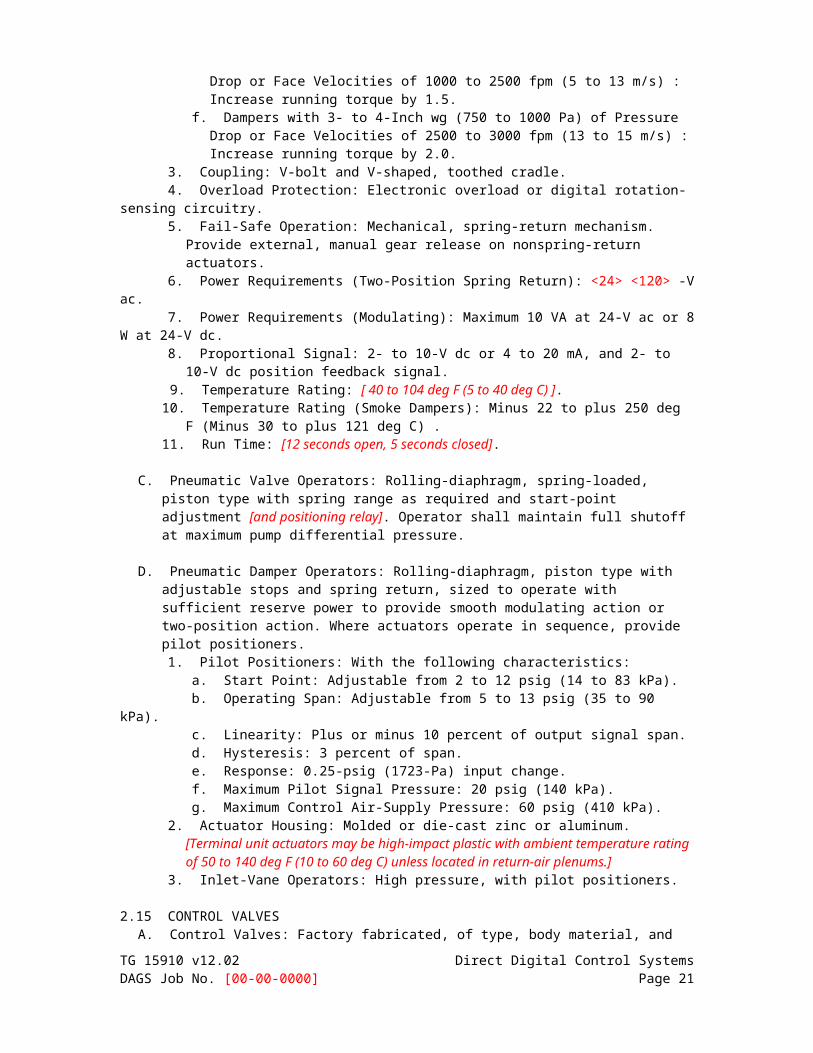
e. Dampers with 2- to 3-Inch wg (500 to 750 Pa) of Pressure Drop or Face Velocities of 1000 to 2500 fpm (5 to 13 m/s) : Increase running torque by 1.5.
f. Dampers with 3- to 4-Inch wg (750 to 1000 Pa) of Pressure Drop or Face Velocities of 2500 to 3000 fpm (13 to 15 m/s) : Increase running torque by 2.0.
3. Coupling: V-bolt and V-shaped, toothed cradle. 4. Overload Protection: Electronic overload or digital rotation-sensing circuitry. 5. Fail-Safe Operation: Mechanical, spring-return mechanism. Provide external, manual
gear release on nonspring-return actuators. 6. Power Requirements (Two-Position Spring Return): <24> <120> -V ac. 7. Power Requirements (Modulating): Maximum 10 VA at 24-V ac or 8 W at 24-V dc. 8. Proportional Signal: 2- to 10-V dc or 4 to 20 mA, and 2- to 10-V dc position feedback
signal. 9. Temperature Rating: [ 40 to 104 deg F (5 to 40 deg C) ]. 10. Temperature Rating (Smoke Dampers): Minus 22 to plus 250 deg F (Minus 30 to plus
121 deg C) . 11. Run Time: [12 seconds open, 5 seconds closed].
C. Pneumatic Valve Operators: Rolling-diaphragm, spring-loaded, piston type with spring range as required and start-point adjustment [and positioning relay]. Operator shall maintain full shutoff at maximum pump differential pressure.
D. Pneumatic Damper Operators: Rolling-diaphragm, piston type with adjustable stops and spring return, sized to operate with sufficient reserve power to provide smooth modulating action or two-position action. Where actuators operate in sequence, provide pilot positioners. 1. Pilot Positioners: With the following characteristics:
a. Start Point: Adjustable from 2 to 12 psig (14 to 83 kPa). b. Operating Span: Adjustable from 5 to 13 psig (35 to 90 kPa). c. Linearity: Plus or minus 10 percent of output signal span. d. Hysteresis: 3 percent of span. e. Response: 0.25-psig (1723-Pa) input change. f. Maximum Pilot Signal Pressure: 20 psig (140 kPa). g. Maximum Control Air-Supply Pressure: 60 psig (410 kPa).
2. Actuator Housing: Molded or die-cast zinc or aluminum. [Terminal unit actuators may be high-impact plastic with ambient temperature rating of 50 to 140 deg F (10 to 60 deg C) unless located in return-air plenums.]
3. Inlet-Vane Operators: High pressure, with pilot positioners. TG 15910 v12.02 Direct Digital Control SystemsDAGS Job No. [00-00-0000] Page 14

2.15 CONTROL VALVES A. Control Valves: Factory fabricated, of type, body material, and pressure class based on
maximum pressure and temperature rating of piping system, unless otherwiseindicated.
B. Hydronic system globe valves shall have the following characteristics: 1. NPS 2 (DN 50) and Smaller: Class [125] bronze body, bronze trim, rising stem,
renewable composition disc, and screwed ends with backseating capacity repackable under pressure.
2. NPS 2-1/2 (DN 65) and Larger: Class 125 iron body, bronze trim, rising stem, plug-type disc, flanged ends, and renewable seat and disc.
3. Internal Construction: Replaceable plugs and stainless-steel or brass seats. a. Single-Seated Valves: Cage trim provides seating and guiding surfaces for plug
on top and bottom. b. Double-Seated Valves: Balanced plug; cage trim provides seating and guiding
surfaces for plugs on top and bottom. 4. Sizing: [ 5-psig (35-kPa) ] <Insert value> maximum pressure drop at design flow rate
or the following: a. Two Position: Line size. b. Two-Way Modulating: Either the value specified above or twice the load pressure
drop, whichever is more. c. Three-Way Modulating: Twice the load pressure drop, but not more than value
specified above. 5. Flow Characteristics: Two-way valves shall have equal percentage characteristics;
three-way valves shall have linear characteristics. 6. Close-Off (Differential) Pressure Rating: Combination of actuator and trim shall
provide minimum close-off pressure rating of 150 percent of total system (pump) head for two-way valves and 100 percent of pressure differential across valve or 100 percent of total system (pump) head.
C. Steam system globe valves shall have the following characteristics:
1. NPS 2 (DN 50) and Smaller: Class 125 bronze body, bronze trim, rising stem, renewable composition disc, and screwed ends with backseating capacity repackable under pressure.
2. NPS 2-1/2 (DN 65) and Larger: Class 125 iron body, bronze trim, rising stem, plug-type disc, flanged ends, and renewable seat and disc.
3. Internal Construction: Replaceable plugs and stainless-steel seats. a. Single-Seated Valves: Cage trim provides seating and guiding surfaces for plug
on top and bottom of guided plugs.b. Double-Seated Valves: Balanced plug; cage trim provides seating and guiding
surfaces for plugs on top and bottom of guided plugs. 4. Sizing: For pressure drop based on the following services:
a. Two Position: 20 percent of inlet pressure. b. Modulating [15-psig (103-kPa) Steam]: 80 percent of inlet steam pressure. c. Modulating [16- to 50-psig (110- to 350-kPa) Steam]: 50 percent of inlet steam
pressure. d. Modulating [More Than 50-psig (350-kPa) Steam]: As indicated.
5. Flow Characteristics: Modified linear characteristics. 6. Close-Off (Differential) Pressure Rating: Combination of actuator and trim shall
provide minimum close-off pressure rating of 150 percent of operating (inlet) pressure.
D. Butterfly Valves: 200-psig (1380-kPa) , 150-psig (1034-kPa) maximum pressure differential, ASTM A 126 cast-iron or ASTM A 536 ductile-iron body and bonnet, extended neck, stainless-steel stem, field-replaceable EPDM or Buna N sleeve and stem seals. 1. Body Style: <Wafer> <Lug> <Grooved>. 2. Disc Type: <Nickel-plated ductile iron> <Aluminum bronze> <Elastomer-coated ductile
iron> <Epoxy-coated ductile iron>. TG 15910 v12.02 Direct Digital Control SystemsDAGS Job No. [00-00-0000] Page 15
3. Sizing: 1-psig (7-kPa) maximum pressure drop at design flow rate.
E. Terminal Unit Control Valves: Bronze body, bronze trim, two or three ports as indicated, replaceable plugs and seats, and union and threaded ends.
1. Rating: Class 125 for service at 125 psig (860 kPa) and 250 deg F (121 deg C) operating conditions.
2. Sizing: 3-psig (21-kPa) maximum pressure drop at design flow rate, to close against pump shutoff head.
3. Flow Characteristics: Two-way valves shall have equal percentage characteristics; three-way valves shall have linear characteristics.
F. Self-Contained Control Valves: Bronze body, bronze trim, two or three ports as indicated, replaceable plugs and seats, and union and threaded ends.
1. Rating: Class 125 for service at 125 psig (860 kPa) and 250 deg F (121 deg C) operating conditions.
2. Thermostatic Operator: <Wax> <Liquid-filled> <integral> <remote> sensor with <integral> <remote> adjustable dial.
2.16 DAMPERS A. Dampers: AMCA-rated, [opposed]-blade design; 0.108-inch- (2.8-mm-) minimum thick,
galvanized-steel or 0.125-inch- (3.2-mm-) minimum thick, extruded-aluminum frames with holes for duct mounting; damper blades shall not be less than 0.064-inch- (1.6-mm-) thick galvanized steel with maximum blade width of 8 inches (200 mm) and length of 48 inches (1220 mm) .
1. Secure blades to 1/2-inch- (13-mm-) diameter, zinc-plated axles using zinc-plated hardware, with [oil-impregnated sintered bronze] [nylon] blade bearings, blade-linkage hardware of zinc-plated steel and brass, ends sealed against spring-stainless-steel blade bearings, and thrust bearings at each end of every blade.
2. Operating Temperature Range: From minus 40 to plus 200 deg F (minus 40 to plus 93 deg C).
3. Edge Seals, Standard Pressure Applications: Closed-cell neoprene. 4. Edge Seals, Low-Leakage Applications: Use inflatable blade edging or replaceable
rubber blade seals and spring-loaded stainless-steel side seals, rated for leakage at less than 10 cfm per sq. ft. (50 L/s per sq. m) of damper area, at differential pressure of 4-inch wg (1000 Pa) when damper is held by torque of 50 in. x lbf (5.6 N x m); when tested according to AMCA 500D.
2.17 AIR SUPPLY
A. Control and Instrumentation Tubing: Copper tubing complying with ASTM B 88, Type K (ASTM B 88M, Type A) or ASTM B 280 Type ACR. 1. Fittings: Cast-bronze solder fittings complying with ASME B16.18; or wrought-copper
solder fittings complying with ASME B16.22, except forged-brass compression-type fittings at connections to equipment.
2. Joining Method: Soldered or brazed.
B. Control and Instrumentation Tubing: ASTM D 2737 Type FR plenum-rated polyethylene, flame-retardant, nonmetallic tubing rated for 30 psig (207 kPa) and ambient temperature range of 10 to 150 deg F (minus 13 to plus 65 deg C) with flame-retardant harness for multiple tubing. 1. Fittings: Compression or push-on polyethylene fittings.
C. Tank: ASME storage tank with drain test cock, automatic moisture removal trap, tank relief valve, and rubber-cork vibration isolation mounting pads.
D. Duplex Air Compressor: Capacity to supply compressed air to temperature-control system. 1. Pressure control with adjustable electric contacts, set to start and stop both
compressors at different pressures. 2. Electrical alternation set with motor starters and disconnect to operate compressors
TG 15910 v12.02 Direct Digital Control SystemsDAGS Job No. [00-00-0000] Page 16

alternately or on time schedule.
E. Simplex Air Compressor: Tank-mounting compressor with capacity to supply compressed air to temperature-control system, with starter and disconnect. 1. Pressure control with adjustable electric contacts, set to start and stop compressor.
F. Compressor Type: <Reciprocating> <Scroll>.
G. Size compressor and tank to operate compressor not more than [30] minutes during a 60-minute period.
H. Compressor Accessories: Low-resistance intake-air filter, and belt guards.
I. System Accessories: Air filter rated for 97 percent efficiency at rated airflow, and
combination filter/pressure-reducing station or separate filter and pressure-reducing station.
J. Refrigerated Air Dryer: Self-contained, refrigerated air dryer complete with heat exchangers, moisture separator, internal wiring and piping, and with manual bypass valve.
1. Heat Exchangers: Air-to-refrigerant coils with centrifugal-type moisture separator and automatic trap assembly.
2. Refrigeration Unit: Hermetically sealed, operating to maintain dew point of 13 deg F (minus 11 deg C) at 20 psig (140 kPa), housed in steel cabinet with access door and panel.
3. Accessories: Air-inlet temperature gage, air-inlet pressure gage, on-off switch, high-temperature light, power-on light, refrigerant gage on back, air-outlet temperature gage, air-outlet pressure gage, and with contacts for remote indication of power status and high-temperature alarm.
K. Desiccant Dryer: Obtains dew point in pneumatic air piping between compressor and tank at least 15 deg F (minus 9 deg C) below inlet-air dew point at design conditions.
L. Pressure Gages: Black letters on white background, 2-1/2 inches (64 mm) in diameter,
flush or surface mounting, with front calibration screw to match sensor, and having a graduated scale in psig (kPa).
M. Instrument Pressure Gages: Black letters on white background, 1-1/2 inches (38 mm) in
diameter, stem mounted, with suitable dial range.
N. Diaphragm Control and Instrument Valves: 1/4-inch (6-mm) forged-brass body with reinforced polytetrafluoroethylene diaphragm, stainless-steel spring, and color-coded phenolic handle.
O. Gage Cocks: Tee or level handle, bronze, rated for 125 psig (860 kPa).
P. Relays: For summing, reversing, and amplifying highest or lowest pressure selection; with adjustable I/O ratio.
Q. Switches: With indicating plates and accessible adjustment; calibrated and marked.
R. Pressure Regulators: Zinc or aluminum castings with elastomeric diaphragm, balanced construction to automatically prevent pressure buildup, and producing flat reduced-pressure curve.
S. Particle Filters: Zinc or aluminum castings with 97 percent filtration efficiency at rated
airflow, quick-disconnect service devices, and aluminum or plastic bowl with metal guard and manual drain cock.
T. Combination Filter/Regulators: Zinc or aluminum castings with elastomeric diaphragm,
TG 15910 v12.02 Direct Digital Control SystemsDAGS Job No. [00-00-0000] Page 17

balanced construction to automatically prevent pressure buildup, and producing flat reduced-pressure curve; with threaded pipe connections, quick-disconnect service devices, and aluminum or plastic bowl with metal guard and manual drain cock.
U. Airborne Oil Filter: Filtration efficiency of 99.9 percent for airborne lubricating oil particles of 0.025 micron or larger.
V. Pressure Relief Valves: ASME rated and labeled. 1. High Pressure: Size for installed capacity. 2. Low Pressure: Size for installed capacity of pressure regulators and set at 20 percent
above low pressure.
W. Pressure-Reducing Stations: Two parallel pressure regulators. 2.18 CONTROL CABLE
A. Control wiring for 24 volt circuits shall be insulated copper 18 AWG minimum and shall be rated for 300 VAC service.
B. Analog signal wiring shall be 18 AWG single or multiple twisted pair. Each cable shall be 100 per cent shielded and have 20 AWG drain wire. Each wire shall have insulation rated to 300 VAC. Cables shall have an overall aluminum-polyester or tinned-copper (cable-shield tape), overall 20 AWG tinned copper cable drain wire and overall cable insulation rated to 300 VAC. Install analog signal wiring in conduit separate from AC power circuits. Circuits operating at more than 100 volts shall be in accordance with DIVISION 16 Electrical.
C. Optical cables shall be duplex 900 mm tight-buffer construction designed for intra-building environments. Sheath shall be UL listed OFNP in accordance with NEC Article 770. Optical fiber shall meet the requirements of FDDI, ANSI X3T9.5 PMD for 62.5/125mm. Field terminate optical fibers with ST type connectors. Connectors shall have ceramic ferrules and metal bayonet latching bodies.
PART 3 - EXECUTION 3.01 EXAMINATION
A. Verify that [conditioned] power supply is available to control units and operator workstation.
B. Verify that pneumatic piping and duct-, pipe-, and equipment-mounted devices are installed before proceeding with installation.
3.02 INSTALLATION A. Install software in control units and operator workstation(s). Implement all features of
programs to specified requirements and as appropriate to sequence of operation.
B. Connect and configure equipment and software to achieve sequence of operation specified.
C. Mount compressor and tank unit on <elastomeric mounts> <spring isolators with 1-inch (25 mm) static deflection> <restrained spring isolators with 1-inch (25-mm) static deflection>. Isolate air supply with wire-braid-reinforced rubber hose. Secure and anchor according to manufacturer's written instructions and seismic-control requirements. 1. Pipe manual and automatic drains to nearest floor drain. 2. Supply instrument air from compressor units through filter, pressure-reducing valve,
and pressure relief valve, with pressure gages and shutoff and bypassvalves.
D. Verify location of thermostats, humidistats, and other exposed control sensors with
Drawings and room details before installation. Install devices [48 inches (1220 mm)] above TG 15910 v12.02 Direct Digital Control SystemsDAGS Job No. [00-00-0000] Page 18

the floor. 1. Install averaging elements in ducts and plenums in crossing or zigzag pattern.
E. Install guards on thermostats in the following locations: 1. Entrances. 2. Public areas. 3. Where indicated.
F. Install damper motors on outside of duct in warm areas, not in locations exposed to outdoor
temperatures.
G. Install labels and nameplates to identify control components. Nameplates shall be permanently attached to HVAC control panel doors. For each field mounted piece of equipment, a plastic or metal engraved tag with equipment name and point identifier shall be attached.
3.03 PNEUMATIC PIPING INSTALLATION
A. Install piping in mechanical equipment rooms inside mechanical equipment enclosures, in pipe chases, or suspended ceilings with easy access. 1. Install copper tubing with maximum unsupported length of 36 inches (915 mm) , for
tubing exposed to view. 2. Install polyethylene tubing in metallic raceways or electrical metallic tubing. Electrical
metallic tubing materials and installation requirements are specified in Division 16 for Raceways and Boxes.
B. Install terminal single-line connections, less than 18 inches (460 mm) in length, with copper or polyethylene tubing run inside flexible steel protection.
C. In concealed locations such as pipe chases and suspended ceilings with easy access,
install [copper] [polyethylene bundled and sheathed] [polyethylene tubing in electrical metallic] tubing. Electrical metallic tubing materials and installation requirements are specified in Division 16 for Raceways and Boxes.
D. In concrete slabs, furred walls, or ceilings with no access, install copper or polyethylene tubing in electrical metallic tubing or vinyl-jacketed polyethylene tubing. 1. Protect embedded-copper and vinyl-jacketed polyethylene tubing with electrical
metallic tubing extending 6 inches (150 mm) above finished slab and 6 inches (150 mm) into slab. Pressure test tubing before and after pour for leak and pinch.
2. Install polyethylene tubing in electrical metallic tubing extending 6 inches (150 mm) above floor line; pull tubing into electrical metallic tubing after pour.
E. Install tubing with sufficient slack and flexible connections to allow for vibration of piping and equipment.
F. Purge tubing with dry, oil-free compressed air before connecting control instruments. 1. Bridge cabinets and doors with flexible connections fastened along hinge side; protect
against abrasion. Tie and support tubing.
G. Number-code or color-code control air piping for future identification and service of control system, except local individual room control tubing.
H. Pressure Gages or Test Plugs: Install on branch lines at each receiver controller and on signal lines at each transmitter, except individual room controllers.
3.04 ELECTRICAL WIRING AND CONNECTION INSTALLATION
A. Install raceways, boxes, and cabinets according to Division 16 for Raceways and Boxes.
B. Install building wire and cable according to Division 16 Electrical. TG 15910 v12.02 Direct Digital Control SystemsDAGS Job No. [00-00-0000] Page 19

C. Install signal and communication cable as indicated below: 1. Conceal cable, except in mechanical rooms and areas where other conduit and piping
are exposed. 2. Install exposed cable in raceway. 3. Install concealed cable in raceway. 4. Bundle and harness multiconductor instrument cable in place of single cables where
several cables follow a common path. 5. Fasten flexible conductors, bridging cabinets and doors, along hinge side; protect
against abrasion. Tie and support conductors. 6. Number-code or color-code conductors for future identification and service of control
system, except local individual room control cables. 7. Install wire and cable with sufficient slack and flexible connections to allow for
vibration of piping and equipment.
D. Connect manual-reset limit controls independent of manual-control switch positions. Automatic duct heater resets may be connected in interlock circuit of power controllers.
E. Connect hand-off-auto selector switches to override automatic interlock controls when
switch is in hand position.
3.05 FIELD QUALITY CONTROL A. Manufacturer's Field Service: Engage a factory-authorized service representative to
inspect[, test, and adjust] field-assembled components and equipment installation, including connections[, and to assist in field testing]. Report results in writing.
B. Perform the following field tests and inspections and prepare test reports: 1. Operational Test: After electrical circuitry has been energized, start units to confirm
proper unit operation. Remove and replace malfunctioning units and retest. 2. Test and adjust controls and safeties. 3. Leak Test: After installation, charge system and test for leaks. Repair leaks and retest
until no leaks exist.4. Pressure test control air piping at 30 psig (207 kPa) or 1.5 times the operating
pressure for 24 hours, with maximum 5-psig (35-kPa) loss. 5. Pressure test high-pressure control air piping at 150 psig (1034 kPa) and low-pressure
control air piping at 30 psig (207 kPa) for 2 hours, with maximum 1-psig (7-kPa) loss. 6. Test calibration of <pneumatic> <electronic> controllers by disconnecting input
sensors and stimulating operation with compatible signal generator. 7. Test each point through its full operating range to verify that safety and operating
control set points are as required. 8. Test each control loop to verify stable mode of operation and compliance with
sequence of operation. Adjust PID actions. 9. Test each system for compliance with sequence of operation.
10. Test software and hardware interlocks.
C. DDC Verification: 1. Verify that instruments are installed before calibration, testing, and loop or leak
checks. 2. Check instruments for proper location and accessibility. 3. Check instrument installation for direction of flow, elevation, orientation, insertion
depth, and other applicable considerations. 4. Check instrument tubing for proper fittings, slope, material, and support. 5. Check installation of air supply for each instrument. 6. Check flow instruments. Inspect tag number and line and bore size, and verify that
inlet side is identified and that meters are installed correctly. 7. Check pressure instruments, piping slope, installation of valve manifold, and self-
contained pressure regulators. 8. Check temperature instruments and material and length of sensing elements.
TG 15910 v12.02 Direct Digital Control SystemsDAGS Job No. [00-00-0000] Page 20

9. Check control valves. Verify that they are in correct direction. 10. Check air-operated dampers. Verify that pressure gages are provided and that proper
blade alignment, either parallel or opposed, has been provided. 11. Check DDC system as follows:
a. Verify that DDC controller power supply is from emergency power supply, if applicable.
b. Verify that wires at control panels are tagged with their service designation and approved tagging system.
c. Verify that spare I/O capacity has been provided. d. Verify that DDC controllers are protected from power supply surges.
D. Replace damaged or malfunctioning controls and equipment and repeat testing
procedures.
3.06 ADJUSTING A. Calibrating and Adjusting:
1. Calibrate instruments. 2. Make three-point calibration test for both linearity and accuracy for each analog
instrument. 3. Calibrate equipment and procedures using manufacturer's written recommendations
and instruction manuals. Use test equipment with accuracy at least double that of instrument being calibrated.
4. Control System Inputs and Outputs: a. Check analog inputs at 0, 50, and 100 percent of span. b. Check analog outputs using milliampere meter at 0, 50, and 100 percent output. c. Check digital inputs using jumper wire.d. Check digital outputs using ohmmeter to test for contact making or breaking. e. Check resistance temperature inputs at 0, 50, and 100 percent of span using a
precision-resistant source. 5. Flow:
a. Set differential pressure flow transmitters for 0 and 100 percent values with 3-point calibration accomplished at 50, 90, and 100 percent of span.
b. Manually operate flow switches to verify that they make or break contact. 6. Pressure:
a. Calibrate pressure transmitters at 0, 50, and 100 percent of span. b. Calibrate pressure switches to make or break contacts, with adjustable differential
set at minimum. 7. Temperature:
a. Calibrate resistance temperature transmitters at 0, 50, and 100 percent of span using a precision-resistance source.
b. Calibrate temperature switches to make or break contacts. 8. Stroke and adjust control valves and dampers without positioners, following the
manufacturer's recommended procedure, so that valve or damper is 100 percent open and closed.
9. Stroke and adjust control valves and dampers with positioners, following manufacturer's recommended procedure, so that valve and damper is 0, 50, and 100 percent closed.
10. Provide diagnostic and test instruments for calibration and adjustment of system. 11. Provide written description of procedures and equipment for calibrating each type of
instrument. Submit procedures review and approval before initiating startup procedures.
B. Adjust initial temperature and humidity set points.
C. Occupancy Adjustments: When requested within 12 months of date of Substantial
Completion, provide on-site assistance in adjusting system to suit actual occupied conditions. Provide up to [three] visits to Project during other than normal occupancy hours for this purpose.
TG 15910 v12.02 Direct Digital Control SystemsDAGS Job No. [00-00-0000] Page 21
3.07 COMMISSIONING: The Commissioning Agent shall be responsible for commissioning the DDC system as specified in the commissioning section of the specifications.
3.08 TRAINING A. The controls contractor shall provide the following training services:
1. One (1) day of on-site orientation by a field engineer who is fully knowledgeable of the specific installation details of the project. This orientation shall, at a minimum, consist of a review of the project as-built drawings, the control system software layout and naming conventions, and a walk through of the facility to identify panel and device locations.
2. General: Provide training course schedule, syllabus, and training materials 15 days prior to the start of training. Conduct training courses for designated personnel in the maintenance and operation of the HVAC and DDC system. Orient training to the specific system being installed under this contract. Use operation and maintenance manual as the primary instructional aid. Operational and maintenance manuals shall be provided for each trainee with four additional sets, two sets delivered for archiving at the project site, one set for the mechanical contractor, and one set for the design engineer. Training manuals shall include an agenda, defined objectives and a detailed description of the subject matter for each lesson. Furnish audio-visual equipment and all other training materials and supplies. A training day is defined as 8 hours of classroom or lab instruction, excluding break and lunch periods, Monday thru Friday, during the daytime shift in effect at the training facility. For guidance, assume the attendees will have a high school education and are familiar with HVAC systems. The minimum amount of training for this project shall be 24 hours.
3. Operator Training: Operator training shall include the detailed review of the control installation drawings, points list, and equipment list. The instructor shall then walk through the building identifying the location of the control devices installed. For each type of systems, the instructor shall demonstrate how the system accomplishes the sequence of operation.
4. From the workstation, the operator shall demonstrate the software features of the system. As a minimum, the operator demonstrate and explain logging on, setting passwords, setting up a schedule, trend, point history, alarm, and archiving the database.
5. Maintenance Training: The system maintenance course shall be taught at the project site within one month after the completion of the operators training. The course shall last for one 8 hour training day. The course shall include answering questions from the last training session, trouble shooting and diagnostics, repair, instructions, preventive maintenance procedures and schedules, and calibration procedures.
END OF SECTION 15910
TG 15910 v12.02 Direct Digital Control SystemsDAGS Job No. [00-00-0000] Page 22


![Stadium Manager’s Monthly Report Regular Session April ... · 4/4/2020 · Cc: Chan, Scott L ; John Fink Subject: [EXT]](https://img.dokumen.tips/doc/110x75/60651b70b4db98566e1eb34b/stadium-manageras-monthly-report-regular-session-april-442020-cc-chan.jpg)