Embed Size (px)
Citation preview
ALTRONIC, INC.712 TRUMBULL AVE.
GIRARD, OHIO 44420
OPERATTI\TG MANIJAI-
E P C - 2 0 O C
V E R S I O N C
SECTION
SECTION
SECTION
SECTION
SECTION
SECTION
SECTION
1
z
5
6
7
GENERAL DESCRIPTION
REQUIRED DATA
CHANNEL DESCRIPTION
DATA ENTRY
OPERATION
INSTALLATION
PARTS LIST
FORM EPC-C OM 4-90
WARNING
TO INSURE RETENTION OF DATA IN MEMORY:
1. DO NOT TINPOWER THE DEVICE II}IILE IN TIIE CONFIGURATION MODE.
2. DO NOT TJNPOWER THE DEVICE FOR AT LEAST TWO MINUTES AFTER LEAVINGCONFIGURATION MODE.

S E C T I O N ] -
GENEI? .AI - DESCR- IPTION

1.0 DESCRIPTION - ALTRONIC EPC-2OOC ENGINE PERFORUANCE CONTROLLER
1 . 1 IGI{ITION TIMING AND AIR/FUEI RATrO CONTROL
T h e A l t r o n i c E P C - 2 0 0 C E n g i n e P e r f o r m a n c e C o n t r o l l e r i s a m i c r o p r o c e s s o r - b a s e de l e c t r o n i c c o n t r o l d e v i c e d e s i g n e d t o m a x i m i z e e n g i n e p e r f o r m a n c e a n de f f i c i e n c y . T h e d e v i c e i s s p e c i f i c a l l y d e s i g n e d t o c o n t r o l i g n i t i o n t i - m i n ga n d a i r / f u e 1 r a t i o o n s p a r k - i g n i t e d , t u r b o c h a r g e d g a s e n g i - n e s a l l o w i n g f o rthe to ta l r ep lacenen t o f t r ad i t i ona l pneuna t i - c con t ro l sys tens . Eng ine RPMp lus up to f ou r o the r ana log i - npu ts can be used as con t ro l va r i ab les ; t hefou r ana log i - npu ts can be sca l . ed to rep resen t des i red eng inee r i ng un i t s .
I G N I T I O N T I M I N G i s a 4 - 2 0 m a o u t p u t s i . g n a l a n d i s a f u n c t i o n t y p i c a l l y o fo n e o r r n o r e o f t h e f o l l o w i n g p a r a m e t e r s : R P M , f u e l n a n l f o l d p r e s s u r e , a i rm a n i f o l d p r e s s u r e , a i r m a n i f o l d t e m p e r a t u r e . A f i f t h , u n s p e c r f i e d v a r i a b l ei s a l s o a v a i l a b l e i f r e q u i r e d .
NOTE: 4 ma = fuJ -1 advance ; 20 ma = fu l l r e ta rd .
A I R / F U E L R A T I O i s c o n t r o l l e d b y c o n t r o l l i n g t h e a i r l f u e 1 p r e s s u r e r a t i o . Aw a s t e - g a t e ( b y - p a s s v a l v e ) i n p a r a l l e l w i t h t h e e n g i n e ' s t u r b o c h a r g e r i sopened o r c l osed to dec rease o r i nc rease the a i r man i fo ld p ressu re . Thedes i red a i r man i fo ld p ressu re i s a f unc t i on ma in l y o f f ue l p ressu re . Theac tua l neasu red a i r r nan i f o l d p ressu re i s compared to t he des i red ca l cu la tedva lue and a s i gna l ( 4 -20 ma) sen t t o t he was te -ga te t o compensa te i n t hep r o p e r d i r e c t i o n . T h e a i - r / f u e 1 p r e s s u r e r a t i o n a y a l s o b e m o d i f i e d a s afunc t i on o f a i r man i fo ld t empera tu re and /o r eng ine RPM.
N O T E : 4 m a = 0 % o p e n ( f u l l y c l o s e d ) ; 2 0 r n a = 1 0 0 % o p e n .
Under ce r ta in cond i t i ons , t he re can be i n te rac t i on be tween the above twofunc t i ons . I f su f f i c i en t a i r man i fo ld p ressu re canno t be ach ieved even w i ththe bypass va l ve f u1 l y c l osed , t he i gn i t j . on t i r n i ng can be re ta rded to i nc reasethe exhaust temperature, thereby provid ing nore energy to the turbochargerso tha t t he a i r man i fo ld p ressu re can be i nc reased and b rough t i n to t hep resc r i bed range . Th i s i s t he a i r / f ue1 ove r r i de cond i t i on . The re i s a l soa s ta r t ove r r i de cond i t i on whe re the bypass va l ve i s kep t f u l l y c l osed andi - g n i t i o n t i m i n g s e t t o a s p e c i f i c v a 1 u e .
I n a d d i t i o n t o t h e t w o a b o v e a n a l o g c o n t r o l f u n c t i o n s , t h e E P C - 2 0 0 C a L s ohas s i x (6 ) use r -p rog rammab le so l i d - s ta te re lay ou tpu ts re la ted to commons ta r t -up sequenc ing func t i ons such as pu rge , ove rc rank , c rank d i sconnec t ,f l ood ing , e t c . Ano the r ou tpu t p rov ides a s i gna l i n t he even t o f ove rspeed ,o v e r l o a d o r t h e l o s s o f a n y i n p u t ; i f t h i s o c c u r s , t h e i g n i t i o n t i n i n g a n dw a s t e - g a t e p o s i t i o n a r e s w i t c h e d t o p r e s e t v a l u e s .
1 1t - l

L.2 EPC TYPICAL CONTROL FI.'NCTIONS
A. IGNITION TIMING RETARD
I g n i t i o n T i m i n g R e t a r d v s . E n g i n e S p e e d ( s )
I g n i t i o n T i n i n g R e t a r d v s . F u e l M a n i f o l d P r e s s u r e ( x )
I g n i t i o n T i m i n g R e t a r d v s . A i r M a n i f o l d P r e s s u r e ( y )
I g n i t i o n T i m i n g R e t a r d v s . A i r M a n i f o l d T e m p e r a t u r e ( z )
I g n i t i o n T i r n i n g R e t a r d v s . U n s p e c j f i e d A n a i o g V a r i a b l e ( v )
The ope ra t i ng va lues fo r t he f unc t j - ons above a re ca l - cu la ted sepa ra te l ya c c o r d i n g t o u s e r e n t e r e d c u r v e s , a n d t h e c o n b i n e d n e t e f f e c t i s i n p l e m e n t e db y t h e E P C - 2 0 0 C C o n t r o l l e r i n a P I D f b r r n a t .
B . A IR /FUEL RATIO
A i r M a n i f o l d P r e s s u r e v s . F u e l M a n l f o l d P r e s s u r e ( x l
A i r M a n i f o l d P r e s s u r e v s . E n g i n e S p e e d ( s )
A i r M a n i f o l d P r e s s u r e v s . U n s p e c i f i e d A n a l o g V a r i a b L e ( v )
A i r Man i fo ld P ressu re vs . A i r Man i fo ld Tempera tu re ( z )
The ope ra t i ng va lues fo r t he f i r s t t h ree va r i ab les a re ca l cu la ted sepa ra te l yacco rd ing to use r en te red cu rves , and the comb ined ne t e f f ec t i s imp lenen tedb y t h e E P C - 2 0 0 C C o n t r o l l e r . T h e r e s u l t a n t a i r / f u e I r a t i . o c a n a l s o b e d i r e c t l ymod i f i ed based on a i r man i fo td t emDera tu re .
C . AUXIL IARY OUTPUT FUNCTIONS ( t yp i ca l )
Pu rge T imer - I gn i t i on 0n (O /4 )
Pu rge T imer - S ta r t i ng Fue l 0n (0 /5 )
S p e e d S w i t c h - C r a n k D i s c o n n e c t ( O / 2 )
Speed Sw i t ch - Runn ing Fue l 0n (0 /3 )
Speed Sw i t ch w i t h T imer - Ove rc rank (0 /6 )
S p e e d S w i t c h w i t h F u e l M a n i f o l d P r e s s u r e L i m i t - F l o o d i n C ( O / 7 )
F a u l t S w i t c h - O v e r s p e e d , O v e r l o a d , L o s s o f I n p u t ( 0 / 8 )
L - 2

)O(Y t-
O -
O
,)' , oF P _< =
O=
FOLal7
1 a
O X O7 w - v l= t A( J ; r _ _ ) a =
-r - v ; - i L l v
L 7 j
= L , l L l O
^ lv t ! O L , ] O L r
a0)UlLr
jLu
crJ
I
o - o - Lt t a l t - Z
u ) a F ( J 9,XdoF 'o
t n) - Yq ? ! - 3d
N
O
aL
_,)LrllL
a
L(Y
N
O
U
F
(n
o-oa
(o
O
N
(YU
F
tr)
O
v_U
F
d-
O
(_)a-)ON
I(JoU
()ooc\
I
o(Ltu
I
U)F Z
CI9l ! F
()zlIL
J
I(L
l--
0co000!000o000BO0
7 - 3

S E C T I O N 2
R.EQIJIR.ED DATA
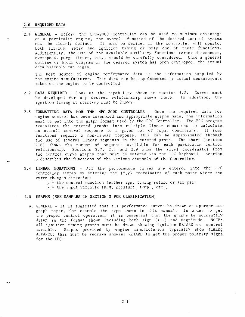
2.0 REQUTR-ED DATA
2 . 1 GENEML - Be fo re t he EPC-200C Con t ro l l e r can be used to max inum advan tageon a pa r t i cu la r eng ine , t he ove ra l l f unc t i on o f t he des i red con t ro l sys temm u s t b e c l e a r l y d e f i n e d . I t m u s t b e d e c i d e d i f t h e c o n t r o l l e r w i l l m o n i t o rh o t h a i r / f u e l r ^ + ; ^ - - r ; - - i + ; o n t i m i n S O I C n r ' n € + h a 5 g f U n C t i O n S .^ 4 L M l l U r B r r A L r - - . - - - . - - - - o - ' I L L J V l l V V l L l l V
A d d i t i o n a l l y , t h e u s e o f t h e a v a i l a b l e a u x i l i a r y f u n c t i o n s ( c r a n k d i s c o n n e c t ,o v e r s p e e d , p u r g e t i m e r s , e t c . ) s h o u l d b e c a r e f u l l y c o n s i d e r e d . O n c e a g e n e r a lou t l i - ne o r b lock d iag ra rn o f t he des i red sys te rn has been deve loped , t he ac tua ld a t a a s s e m b l y c a n b e g j , n .
The bes t sou rce o f eng ine pe r fo rmance da ta i s t he i n fo rma t i on supp l i ed bythe eng ine manu fac tu re r . Th i " s da ta can be supp lemen ted by ac tua l measu remen tst a k e n o n t h e e n g i n e t o b e c o n t r o l l e d .
2 .2 DATA REQUIRED - Look a t t he capab i l i t y shown i n sec t i onb e d e v e l o p e d f o r a n y d e s i r e d r e l a t j - o n s h j p s h o w n t h e r e .i ^ r . i t i n n + ; m : - ^ ^ + ^ + ^ , + , , ^ m U S t b e k n O W n -r B l r I L l v l l L l r l r r r r S 4 L J L 4 r L - u P
2.4 LINEAR EQUATIONS - A11 the per formanceC o n t r o l l e r s i r n p l y b y e n t e r i n g t h e ( x , y )cu rve changes d i rec t i on :
I = t he con t ro l f unc t i on (e i " t he r i gn .x = t he i npu t va r i ab le (RPM, p ressu re
1 . 2 . C u r v e s m u s tI n e d d i t i o n . t h c
cu rves a re en te red i n to t he EPCcoord ina tes o f each po in t whe re the
f i m i n o r e f r r i n r r i r n c i l
f a m n o t c )r L v r r r H . r v u v . /
2.3 FORMATTING DATA FOR TTIE EPC-2OOC CONTROLLER Once the requ i red da ta f o r
eng i -ne con t ro l has been assemb led and app rop r i a te g raphs made , t he i n fo r rna t i onmus t be pu t i n to t he g raph fo r rna t used by t he EPC Con t ro l l e r . The EPC p rog ramt r a n s l a t e s t h e e n t e r e d g r a p h s i n t o m u l t l p l e l i n e a r e q u a t i o n s t o c a l c u l a t ea n o v e r a l l c o n t r o l r e s p o n s e t o a g i v e n s e t o f l n p u t c o n d i t i o n s . I f s o m ef u n c t i o n s r e q u i r e a n o n - l i n e a r r e s p o n s e , t h i s c a n b e a p p r o x r m a t e d t h r o u g ht h e u s e o f s e v e r a l l i n e a r s e g m e n t s i n t h e e n t e r e d g r a p h . T h e c h a r t ( s e c t t o n
2 . 6 ) s h o w s t h e n u n b e r o f s e g m e n t s a v a i L a b L e f o r e a c h p a r t i c u l a r c o n t r o lr e l a t i o n s h i p . S e c t i o n s 2 . 7 , 2 . 8 a n d 2 . 9 s h o w t h e ( x , y ) c o o r d i n a t e s f r o mthe con t ro l cu rve g raphs tha t mus t be en te red v ia t he EPC keyboa rd . Sec t l on3 desc t i bes t he func t i ons o f t he va r i ous channe l s o f t he Con t ro l l e r .
2.5 GMPHS (SEE SMPLES rN SECTTON 3 FOR CLARTFTCATTON)
A . GENERAL - I t i s sugges ted tha t a l l pe r fo rmance cu rves be d rawn on app rop r i a teg raph pape r , f o r examp le t he t ype shown i n t h i s nanua l . I n o rde r t o ge tthe p rope r con t ro l ope ra t i on , i t i s essen t i a l t ha t t he g raphs be accu ra te l yd rawn i n t he f o rma t shown i nc lud ing bo th s i gn ( * , - ) and magn i tude . NOTE:A11 i gn i t i on t i r n i ng g raphs nus t be d rawn show ing i gn i t i on RETARD vs . con t ro lva r i ab le . G raphs p rov ided by eng ine nanu fac tu re rs t yp i ca l 1y show t im ingADVANCE; t h i s mus t be red rawn show ing RETARD to ge t t he p rope r po la r i t y s i gnsf o r t h e E P C .

2.6 FIINCTION CTI,ART
N O . O FSEGMENTS EPC EXAMPLE
DESCRIPT ION AVAILABLE CHANNELS SEE SECTION 3
Ign i t i on T in ing Re ta rdvs . Eng ine Speed
5 J 1 - J 6 i . 2
I gn i t i on T im ing Re ta rdvs . Fue l Man i fo ld P ressu re
A 3 9 - 4 4 J , 4
I gn i t i on T i -m ing Re ta rdvs . A i r Man i fo ld P ressu re
A 4 5 - 5 0 5
Ign i t i on T im ing Re ta rdvs. Ternperature
4 5 1 - 5 6 6 , 7
Ign i t i on T im ing Re ta rdv s . U n s p e c i f i e d V a r i a b l e
A 5 7 - 6 2 8
A i r Man i fo ld P ressu revs . Eng ine Speed
63 -66 v
Ai r Man i fo ld P ressu rev s . F u e l M a n i f o l d P r e s s u r e
A 6 7 - 7 2 1 0 , 1 i
A i r Man i fo ld P ressu revs . Unspec i f i - ed Va r i ab le
7 3 - 7 6 T2
Ai r Man i fo ld P ressu revs. Temperature
M u l t i p l i e r 7 7 - 7 9 1 3
a aL - L

2.7 IGNITION TIMING CONTROL
Nunbers i n pa ren thes i s (XX) i nd i ca te t he EPC channe l number used .
0u tpu t : ITR = i gn i t i on t i n i ng re ta rd [ 4 -20na ] (05 )
I n p u t s : s = R P M ( 0 0 )
x = f u e l r n a n i f o l d p s i ( 0 1 )y - a i r r nan i f o l d ps i . ( 02 )z - a i r r nan i f o l d t e rnp . (03 )v - u n s p e c i f i e d v a r i a b l e ( 0 4 )
Input Range v u L P u L U s e r E n t r i e sMeasured Inpu t - s [RPM] Ou tpu t Fac to r - ITRss ( ( 3 i ) I T R s = ( 3 2 ) ( 3 1 ) , ( 3 2 )s = ( 3 1 ) - + ( 3 3 ) I T R s = ( s 2 ) , ) ( 3 4 ) ( 3 3 J , ( 3 4 )s = ( 3 3 ) - + ( 3 5 ) I T R s = ( 3 4 ) + ( 3 6 J ( 3 5 ) , ( 3 6 )s = ( 5 5 ) + ( 3 7 ) I T R s = ( 3 6 ) - + ( 3 8 ) ( 3 7 ) , ( 3 8 )s ) ( 3 7 ) I T R s = ( 3 8 )
Measu red Inpu t - x [ f ue1 ps i ] Ou tpu t Fac to r - ITRxx ( ( 3 9 ) I T R x = ( 4 0 ) ( 3 9 ) , ( 4 0 )x = ( 3 9 ) - + ( 4 1 ) I T R x = ( 4 0 ) - + ( 4 2 ) ( 4 1 ) , ( 4 2 )x = ( a 1 ) - + ( 4 3 ) I T R x = ( 4 2 ) - > ( 4 4 ) ( 4 3 ) , ( 4 4 )x ) ( 4 3 ) I T R x = ( 4 4 )
N leasu red Inpu t - y [ a i r ps i ] Ou tpu t Fac to r - ITRyy < (4s ) I rRy = (46 ) ( 4s ) , ( 46 )
(as ) -+ (a7 ) I rRy= (46 ) - ' ( 48 ) ( 47 ) , ( 48 )(a7 ) -+ ( a9 ) ITRy = (48 ) * ( s0 ) ( 49 ) , ( s0 )
y > (4s ) I rRy = ( s0 )
l i l easu red Inpu t - z [ t emp . ] Ou tpu t Fac to r - ITRzz ( ( 5 1 ) I T R z = ( 5 2 ) [ 5 1 ) , ( 5 2 )z - ( s l l - + ( s3 ) ITRz = ( s2 ) - ' ( s4 ) ( s3 ) , ( s4 )z - ( s3 l - ' ( s s ) ITRz = ( s4 ) -> ( s6 ) ( ss ) , ( s6 )z ) ( 5s ) ITRz = (56 )
M e a s u r e d I n p u t - v [ u n s p e c i f i e d ] O u t p u t F a c t o r - t T R vv ( ( s7 ) ITRv = ( s8 ) ( s7 ) , ( s8 )v - ( 5 7 ) - + ( 5 9 ) I T R v = ( 5 8 ) * ( 6 0 ) ( 5 9 ) , ( 6 0 )v = ( 5 9 ) - + ( 6 1 1 I T R v = ( 6 0 ) - . > ( 6 2 ) ( 6 1 ) , ( 6 2 )v ) ( 6 1 ) I T R v = ( 6 2 )
C a l . c u l a t e : I T R c = C a l c u l a t e d i g n i t i o n t i m i n g r e t a r dITRc = ITRs + ITRx + ITRy + ITRz + ITRv
ITRd = Ign i - t i on t im ing re ta rd des i red Use r En t r i esI f ITRc < ( I2 ) , ITRd = ITRci f I T R c > ( 1 2 ) , I T R d = ( 1 2 )
Cond i t i ons Output Ins t ruc t ion
S t a r t o v e r r i d e [ S 0 = 1 ] H o l d I T R = ( 1 4 )
Norna l Ope ra t i on [S0 = AFO = 0 ] ITR = ITRd , con t ro l i n P ID fo rma t
A i r / f ue l ove r r i de [AFO = 1 ]y < y r I T R = I T R d + 1 d e g . < ( 1 5 ) + I T R c < ( 1 2 )
H o l d f o r ( 1 6 ) s e c s . , t h e n r e p e a t
y > y r I T R = I T R p r e s e n t - 1 d e g . > I T R dH o I d f o r ( 1 7 ) s e c s . , t h e n r e p e a t
ITR = ITRd and y > y r , t hen AFO -> 0 ITR = ITRd
NOTE: A IR /FUEL OVERRIDE IS INOPERATIVE WHEN (15 ) - 0
^ t
( r 2 ) , ( 1 4 ) , ( 1 5 )( 1 6 ) , ( 1 7 )

2.8 ArR/FUEL PRESSURE RATrO CONTROL
Numbers i n pa ren thes i s (XX) i nd i ca te t he EPC channe l nunbe r used .
Ou tpu t : WGP = was te ga te pos i t i one r l 4 -20na ] (06 )
I n p u t s : s = R P M ( 0 0 )x = f u e l n a n i f o l d p s i ( 0 1 )y = a i r m a n i f o l d p s i ( 0 2 )z = a : - r man i fo ld t enp . (03 )
v = u n s p e c i f i e d v a r i a b l e t 0 4 )
Input RangeMeasured Inputs < (63 )s = ( 6 3 ) - + ( 6 5 )s ) ( 6s )
Measured Inputx ( ( 6 7 )x = ( 6 7 ) - + ( 6 9 )
x = ( 6 9 ) - + ( 7 1 )x ) ( 7 1 )
Measured Inputv ( ( 7 3 )v = ( 7 S ; * ( 7 5 )v > ( 7 5 )
F o r a l l z
C a l c u l a t e : y ' cy t c
Cond i t i on
- x I f u e l p s i ]
- v I unspec i f i - ed ]
- s I R P M ]
ca 1 cu la ted( y ? s + y r x
a i r m a n i f o l d p s i ( 0 7 )* y ' v ) X ( 7 7 )
U s e r E n t r i e s
[ 6 3 J , ( 6 4 )( 6 5 ) , ( 6 6 )
( 6 7 ) , ( 6 8 )( 6 9 ) , ( 7 0 )( 7 r ) , ( 72 )
( . 7 3 ) , ( 7 4 )( 7s ) , ( 76 )
( 7 8 ) , ( 7 9 )
U s e r E n t r i e sD i s p l a y ( 7 7 )
Ou tpu t I ns t ruc t i - on
Ho ld WGP
D e c r e a s e W G P ( P I D f o r m a t )
I n c r e a s e W G P ( P I D f o r m a t )
Ho ld WGP = 0e ,
WGP = 0%
Output0utput
Y t c s =
/ t c s =
I r c s =
0utput
/ t c x =
Y r c x =
Y t c x =
0utput
I t c v =
I t c v =
Y t c v =
F a c t o r( 6 4 )( 6 4 ) - +
(6s )Fac to r( 6 8 )( 6 8 ) *( 7 0 ) *( 7 2 )
Fac to r( 7 4 )( 7 4 ) - ,( 7 6 )
( 7 8 ) z
- y t s
( 6 6 )
- y t x
( 7 0 )( 7 2 )
- y t v
( 7 6 )
+ ( 7 9 )
y = y ' c
y < y ' c
y > y ' c
I f WGP = Oeo
I f i n s t a r t
a n d y ( y ' c , t h e n A F O = 1
o v e r r i d e I S O = 1 ]
. AL - +

FIG.2
TYPICAL EPC GRAPHS
DATA SUPPLIED BY ENGINI MANUFACTURE
1 0( 4 0 0 , 9 )
TNGINTTIMINGDIGRTESBTDC
1 0 0 200
TNGINI RPN/
300 400
ABOVE GRAPH REDRAWN IN EPC DATA FORMAT
1 0
TNGINETIM|NG sDIGRETSRETARD
(cH37,CH 38)/ " a n r \ \
: , r ' ' I ( cuag ,cH38)
( 4 0 0 , 0 )200 300
TNGINE RPM
/ l q n o rl t
(\
0 0 , 6I
\
\
f " - " , ' " '
(2so,o)r l
400
2 - 5

2.9 DISCRETE OUTPUT C}I,ANNELS
Numbers in paren thes is (XX) ind ica te EPC channe l number used.
SYMBOL TYPE DESCRIPTION USER ENTRIES
T / T Input q f o r f n r r o r r i . ] a f q n l\ U V J None
o/2 0utpu tN . C .
R P I I s e t p o i n t , s p e e d e x c e e d s ( 8 0 ) ( 8 0 )
o/3 0utputN . 0 .
R P I l s e f n n i n l c n e c . l e y . c c , l c l ' R 1 l\ " . ) ( 8 1 )
o/4 0utputN . C .
T i m e d e l a y ( 8 2 ) f r o m e n d o f S 0 [ 1 - + 0 ] ( 8 2 )
n / q 0utputN . 0 .
T i m e d e l a y ( 8 5 ) f r o m e n d o f S O [ 1 + 0 ] ( 8 3 )
o /6 0utputN . C .
Perm iss i ve l os t i - f t ime f rom end o f SO
[ 1 + 0 ] i s l o n g e r t h a n t i m c ( 8 4 ) a n ds p e e d i s b e l o w ( 8 5 )
( 84 ) , ( 8s )
o/7 OutputN . C .
P e r m i s s i v e l o s t i f f u e l p s i i s g r e a t e rt h a n ( 8 6 ) a n d s p e e d i s b e l o w ( 8 7 )
( 8 6 ) , ( 8 7 )
o/8 0utputN . C .
P e r m i s s i v e l o s t i f x I f u e 1 p s i ] > ( 8 8 )o r i f s [ R P M ] > ( 8 9 ) o r i f a n y i n p u t- i ^ - . ^ 1 . ' ' ' - ' ' ^ r s i s l o s tJ a B l l d r L r f , L r v w
W h e n 0 / 8 t r i p s : I T R = ( 0 9 ) ; W G P = ( 1 0 )
F i r s t o u t f a u l t i n d i c a t i o n i n C i l 9 1 .
( 8 8 ) , ( 8 9 )
( 0 9 ) , ( 1 0 )
S E C T I O N 3
CHAI\INEI- I )ESCR"IPTION

3.0 EPC CHANNEL DESCRIPTION
OVERVIEW:
DISPLAY ONLY0 0 *0 1 *02*0 3 *0 4 *0 5 *0 6 *0 7 *0 8 *
OVERRIDING0 9I U
1 1t 213L 41 5l 6T 7
CHANNELSEng ine speed ( s )Ana log i npu t no . 1 , f ue l man i fo ld p ressu re ( x )
Ana log i npu t no . 2 , a i r man i fo ld p ressu re ( y )
Ana log i npu t no . 3 , a i r r nan i f o l d t enpe ra tu re ( z )
Ana log i npu t no . 4 , unspec i f i ed va r i ab le ( v )
I gn i t i on T im ing Re ta rd ( ITR) ou tpu tWas te Ga te Pos i t i on (WGP) ou tpu t (% open )
Ca lcu la ted a i r man i fo ld p ressu reIgn i t i on t i r n i ng (deg rees BTDC)
CONSTANTSDefau l t va lue - ITRDe fau l t va lue - WGPFu11 advance t im ing po in t ( deg rees BTDC)
ITR - max imum l im i tT ine de lay be fo re 0 /8 ac t i veITR du r i ng s ta r t ove r r i deITR l im i t l n a i r l f ue l ove r r i - deT ime be tween re ta rd s teps - a i r ' l f ue l ove r r i de
T ine be tween advance s teps - a i r / f ue l ove r r i de
D .
C. SCAL ING FACTORS18 Sca l i ng - deg rees o f r e ta rd f o r ITR ou tpu t
Ig -21 Sca l i ng - ana log i npu t no . 1 , f ue l man i fo ld p ressu re ( x )
22 -24 sca l i ng - ana log i npu t no . 2 , a i r nan i f oLd p ressu re ( y )
2 5 - 2 7 S c a l i n g - a n a l o g i n p u t n o . 3 , a i r m a n i f o l d t e n p e r a t u r e ( z )
28 -30 Sca l i ng - ana log i npu t no . 4 , unspec i f i ed va r i ab le ( v )
tr
IGNIT ION T IMING RETARD ( ITR) CURVE COORDINATES
3 1 - 3 8 I T R v s . R P M c o o r d i n a t e s ( s )
39 -44 ITR vs . f ue l r nan i f o l d p ressu re coo rd ina tes ( x )
4 5 - 5 0 I T R v s . a i r m a n i f o l d p r e s s u r e c o o r d i n a t e s ( y )
5 1 - 5 6 I T R v s . a i r m a n i f o l d t e n p e r a t u r e c o o r d i n a t e s ( z )
5 7 - 6 2 I T R v s . u n s p e c i f i e d v a r i a b l e c o o r d i n a t e s ( v )
CALCULATED A IR MANIFOLD O*U"U*U (Y 'C ) CURVE COORDINATES
6 3 - 6 6 y r c v s . R P M c o o r d i n a t e s ( s )
6 7 - 7 2 y r c v s . f u e l r n a n i f o l d p r e s s u r e c o o r d i n a t e s ( x )
7 3 - 7 6 y r c v s . u n s p e c i f i e d v a r i a b l e c o o r d j - n a t e s ( v )
TEMPERATURE CORRECTION FACTORS - YICTempera ture cor rec t ion mul t ip l ie rS lope o f tenpera ture mul t iP l ie rOf fse t o f tempera ture mul t iP l ie r
* D i sp lay on l y channe l s ; no da ta en te red on these channe l s .
1 1 *
/ 6
3 - 1

G. DISCRETE OUTPUTS8 08 18 28 38 4X \
8 66 /
8 88 9
RPM l i rni t to tr ip O/2RPM l im i t to t r ip 0 /3Time l i rni t to tr ip output 0/4Time I j -mit to tr ip output O/5Time l i rni t for output 0/6Safe RPM for output 0/6Pressure l in i t fo r ou tpu t O/7Safe RPM for output O/7Pressure to t r ip O/8 - de fau l t modeRPM l im i t to t r ip O/8 - de fau l t node
H. DIAGNOSTIC CHANNELS9 0 "9 1 *
9 29 39 4
br ror messageFi rs t -ou t fau l t fo r ou tpu t O/8
I . PI RESPONSE FACTORSReset response cont ro l - ITRProport ional band control - WGPReset response cont ro l - WGP
J. SET-UP CHANNELS9 8 N o . o f s e n s e d t e e t h ( 5 0 0 m a x . )99 Password /con f i gu ra t i on
* D i s p l a y o n l y c h a n n e l s ; n o d a t a e n t e r e d o n t h e s e c h a n n e l s .

CIIANNELS 00-08: DISPLAY ONLY CILANNELS
Channe ls 00 -08 a re used to d i sp lay da tao n t h e s e c h a n n e l s .
a s d e s c r i b e d b e 1 o w . No da ta i c i n n r r f f o r l
C}IANNEL OO:
C M N N E L O 1 :
D i s p l a y s e n g i n e R P M .
D i s p l a y s t h e p r e s e n t v a l u efueL nan i f o l d p ressu re .
o f a n a l o g i n p u t n o . / - , \ + , , - i ^ ^ 1 1 , ,\ ^ J r L I P L u d r L y
CI I {NNEL 02 : D i sp lays t he p resen t va lue o f ana log i npu t no_a i r r n a n i f o l d p r e s s u r e .
CFIANNEL 03:
CTIANNEL 04:
) / \ ' l f ' h j ^ ^ l l \ /t ) t ) t e l y l w a r L l
Disp lays t he p resen t va luea i r man i fo ld t enpe ra tu re .
o f a n a l o g i n p u t n o . ( - \ + r , * i ^ ^ 1 1 . ,\ L . ) t L ) t P L w a L L !
D j - s p l a y s t h e p r e s e n t v a L u e o f a n a l o g i n p u t n o . 4 ( v ) , f o r e x a m p l e ,exhaus t t empera tu re .
C ITANNEL 05 : D i sp laysw h i c h i sNOTE: 4
C I IANNEL 06 : D i sp laysN O T E : 4
t h e o u t p u t v a l u e o f I g n i t i o n T i m i n gi n t e r n a l l y c a l c u J . a t e d b y t h e E P C .m a o u t p u t = n o r e t a r d ; 2 0 m a o u t p u t
R e t a r d { ' I T R ) i n d e g r e e s
= f u l 1 r e t a r d .
t h e W a s t e G a t e P o s i t i o n ( W G P ) j - n P e r C e n t O p e n .na ou tpu t = Oeo Open t 20 ma ou tpu t = 100e" Open .
C I I A N N E L 0 7 : D i s p l a y s t h e D e s i r e d A i r M a n i f o l d P r e s s u r e ( y ' c ) w h i c h i s i n t e r n a l l yc a l c u l a t e d b y t h e E P C . T h e E P C c o n p a r e s t h i s t o t h e a c t u a l A i rM a n i f o l d P r e s s u r e ( C h a n n e l 0 2 ) a n d c o n t i n u a l l y s e e k s t o a d j u s t t h eW a s t e G a t e p o s i t i o n t o b r i n g t h e r e a d i n g o f C h a n n e l 0 2 e q u a l t othe des i red vaLue shown on Channe l 07 .
CFTANNEL 08 : D i sp lays t he Ign i t i on T im ing po in t i n deg rees BTDC (pos i t i ve nu rnbe r )or ATDC (negat i -ve number) .NOTE: Channe l 08 = ChanneL l l n i nus ChanneL 05 .
3 - 3

CHANNELS 09-17: OVERRIDING CONSTANTS
Channe ls 09 -17 a re va lues wh ich con t ro l ce r ta in aspec ts o f t he EPC p rog ramove r r i d i ng the no rma l con t ro l cu rves .
CHANNEL 09 : DEFAULT VALUE 0F ITR (deg rees o f r e ta rd ) - Th i s j . s t he va lue o f( requ i red ) I gn i t i on T im ing Re ta rd t ha t w i l l be ou tpu t ted i f t he de fau l t ou tpu t
O /8 i s t r i pped . A compromise t i n i ng va lue tha t i s sa fe unde r a l lcond i t i ons shou ld be chosen fo r t h i s en t r y .
CMNNEL 1O:( requ i red )
CFIANNEL 11 :f r p n r r i r o r l ' )
CIIANNEL 13:( requ i red )
CHANNEL 14( requ i r ed )
CHANNEL 15(op t i ona l )
CHANNEL 16( o p t i o n a l )
CHANNEL 17(op t i ona l )
DEFAULT VALUE 0F WGP ( i n e " open ) - Th i s i s t he Was te Ga te Pos i t r onin Pe r Cen t Open tha t w i l l be ou tpu t ted r - f t he De fau l t 0u tpu t O /8i s t r i p p e d . A c o r n p r o m i s e v a l u e t h a t i s s a f e u n d e r a l l c o n d i t i o n sshou ld be chosen fo r t h i s en t r y .
FULL ADVANCE T IMING (deg rees BTDC) - En te r t he va lue o f I gn i t l - onT i n i n g i n d e g r e e s B T D C w h e n t h e E P C i s o u t p u t t i n g z e r o r e t a r d . T h i si npu t mus t be co r rec t f o r Channe l 08 to g i ve t he co r rec t I gn i t j _onT im ing va lue du r i ng ope ra t i on . NOTE : i f t he f u l I advance t im ingi s a l t e r e d a t t h e i g n i t i o n s y s t e m , t h e v a l u e i n C h a n n e l 1 1 m u s tbe changed acco rd ing l y .
C I IANNEL 12 : MAX. VALUE 0F ITR (deg rees o f( requ i red ) o f I gn i t i on T i rn ing Re ta rd t o be
I i m i t m a y d e p e n d o n t h e i g n i t i o nimposed by t he pa r t i cu la r eng ine
retard) - Enter the rnaximum amounta l L o w e d u n d e r a n y c o n d i t i o n . T h i ss y s t e n b e i n g u s e d o r m a y b e a I i m i t
a n o l i c a t i o n .
T IME DELAY AFTER START-UP BEFORE ARMING DEFAULT OUTPUT O/8 ( secs . )Enter the maxinum amount of t ine that the Defaul t Output O/8 shouldb e l o c k e d - o u t a f t e r t h e S t a r t O v e r r i d e s i g n a l e n d s . T h i s l o c k - o u tt i m e i s r e q u i r e d t o a l l o w t h e e n g i n e t o s t a r t a n d s t a b i l i z e b e f o r ethe De fau l t Ou tpu t i s a rmed .
VALUE 0F ITR DURING START OVERRIDE (deg rees o f r e ta rd ) - En te r t hev a l u e o f I g n i t l o n T i n i n g R e t a r d d e s r r e d d u r i n g s t a r t o v e r r i d e w h e ni n p u t I / 1 i s a c t i v e .
MAX. VALUE 0F ITR ALLOWED IN A IR /FUEL OVERRIDE (deg rees o f r e ta rd )En te r t he max i rnum va lue o f I gn i t i on T im ing Re ta rd t o be a l l oweddur ing A i r /Fue1 Ove r r i de mode . Th i s l im i t s how fa r t he i gn i t i ont i n i ng rnay be re ta rded i n an e f f o r t t o i nc rease exhaus t t empera tu refo r i nc reased tu rbocha rge r ou tpu t (boos t ) . A t yp i " ca l va lue i s 2d e g r e e s .
T IME DELAY BETWEEN RETARD STEPS DURING A IR /FUEL OVERRIDE (secs . )En te r t he t i ne de lay be tween i gn i t i on t im ing RETARD s teps du r i ngthe A i r /Fue1 Ove r r i de mode . Th i s de lay i s requ i red to a11ow theeng ine to respond to t he i nc renen ts o f i gn i t i on t im ing re ta rd wh i cha re i np lemen ted to ob ta in add i t i ona l exhaus t t enpe ra tu re and thusadd i t i ona l a i - r capab i l i t y f r om the tu rbocha rge r . A t yp i ca l va luei s 1 2 0 s e c o n d s .
T IME DELAY BETWEEN ADVANCE STEPS DURING A IR /FUEL OVERRIDE (secs . )En te r t he t i -me de lay be tween i gn i t i on t i n i ng ADVANCE s teps du r i ngthe A i r /Fue1 Ove r r i de mode . Th i s de lay i s requ i red to a11ow theeng ine to respond to t he i nc remen ts o f i gn i t i on t im ing advance asadd i t i ona l a i r i s be ing made ava i l ab le by t he tu rbocha rge r . A t yp i ca lva lue i s 5 seconds .
3 - 4

CIIANNEL 18: IGIIITION TIMING RETARD MNGE (required)
Channe l 18 i s t he range o f I gn i t i on T im ing Re ta rd ( i n deg rees ) rep resen ted bythe 4 -20 ma ITR ou tpu t s i gna l . Th i s nu rnbe r shou ld equa l t he range o f t hepa r t i cu la r i gn i t i on sys tem be ing used :
A l t r o n i c I I - C P U : 4 8 . 0 d e g r e e s - m e m o r y c h i p c o d e A36 .0 deg rees - memory ch ip code B24 .0 deg rees - menory ch ip code C
A l t r o n i c I I I - C P U : 8 . 0 d e g r e e s - m e n o r y c h i p c o d e D , 2 - c y c l e1 6 . 0 d e g r e e s - n e n o r y c h i p c o d e D , 4 - c y c 1 e
CMNNELS 19-30: ANALOG INPUT SCALING (required)
Channe ls 19 -30 sca le t he fou r ana log i npu t s j . gna1s .1 - 5 v o l t o r 4 - 2 O m a s i s n a l .
The j -nputs must be a noninal
Examp le :
This p rocessthe channel
Ana log i npu t no . 1 i s f ue l p ressu re w i th a t r ansduce r w i t h a no rn ina lr a n g e o f 0 - 1 5 p s i .
A c t u a l v o l t a g e o u t p u t w i t h 0 p s i :E n g i n e e r i n g U n i t s ( p s i ) @ M i n . s i g n a l :E n g i n e e r i n g U n i t s ( p s i ) @ 5 V . s i g n a t :
1 . 1 5 ( C h a n n e J . 1 9 )0 0 . 0 ( C h a n n e l 2 0 )1 4 . 9 ( C h a n n e l 2 i )
i s r e p e a t e d f o r a I l a n a l o g i n p u t s b e i n g u s e d .numbers f o r each pa r t i cu la r ana log i npu t :
T h e t a b l e b e l o w g i v e s
* MINIMUM VOLTAGE** ENGR. UNITS AT* * ENGR. UNITS AT
M I N . V . I N P U T . . .5 V . I N P U T
ANALOG INPUTN 0 . 1 N 0 . 2 N 0 . 3 N 0 . 4
1 9 2 2 2 5 2 82 0 2 3 2 6 2 92 1 2 4 2 7 3 0
CTIAN.CHAN.CHAN.
* The MIN IMUM VOLTAGES shou ld be en te red i n t he f o rm X .XX .
* * Fo r each ana log i npu t , t he eng inee r i ng un i t s a t M IN . vo l t age i npu t mus t been te red BEFORE the eng inee r i ng un i t s a t 5V . i npu t . When en te r i ng t heeng inee r i ng un i t s a t m in imun vo l t age , en te r t he dec ina l po in t and theapp rop r i a te number o f en t r i es ( ze ros i f necessa ry ) t o g i ve t he des i redreso lu t i on a t 5V . EXAMPLES:
I f r a n g e i s 0 - 1 5 p s i , e n t e r 0 . 0 ( 1 5 . 0 @ 5 V . )I f r a n g e i s 0 - 1 0 0 p s i , e n t e r 0 . 0 ( 1 0 0 . 0 @ S V . )
NOTE: I t i s r ecommended tha t p ressu res be en te red w i - t h one d ig i t a f t e r t hedec i rna l po in t (XX .X ) and tenpe ra tu res be en te red i n who le numbers (XXX)fo r ease o f r ead ing on the EPC d i sp lay . Any des i red fo rma t no t exceed ingfour s igni f icant f igures may be used but the fornat must be the samefo r bo th t he M IN . V . and 5V . eng inee r i ng un i . t en t r i es .
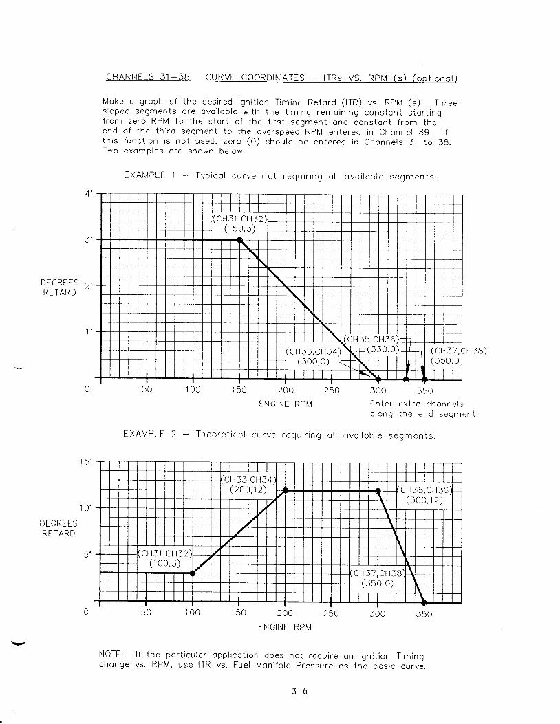
C H A N N E L S 3 1 - 3 8 : C U R V E C O O R D I N A T T S - t T R s V S . R P M ( s ) ( o p t i o n c t )
Moke o g roph o f t he des i red l gn i t i on T im ing Re to rd ( t t n ) vs . RpM (s ) . Th rees l o p e d s e g m e n t s o r e o v o i l o b l e w i t h t h e t i m i n g r e m o i n i n g c o n s t o n t s t o r t i n gf rom ze ro RPM to t he s t c r i o f t he f i r s t segmen t ond cons ton t f r om theend o f t he t h i rd segmen t t o t he ove rspeed RPM en te red i n chcnne l 89 . l ft h i s f unc t i on i s no t used , ze r -o (0 ) shou ld be en te red i n chonne l s 3 .1 t o 38 .Two exomp les o re shown be low :
E X A M P L E 1 - T y p i c c l c u r v e n o t r e q u i r i n g c l l o v o i l o b l e s e g m e n t s .
D T G R E E SRETARD
DEGREESRETARD
100 150 200 250
ENGINE RPIV
300 350
E n t e r e x t r o c h o n n c l sn l n n n l h o o a l , < ^ ^ m ^ ^ l" ' " " Y
, J ! g r r t - l I r
t X A I V P L E 2 _ _ T h e o r e t i c o l c u r v e r e q u i r i n g o l l o v c i l c b l e s e g m e n t s .
150 200 250
E N G I N E R P M
300
NOTE: l f the por t i cu lo rchonge vs . RPM, use ITR
cpp l i co t i on does no t requ i re on l gn i t i on T im ingvs . Fue l Mon i fo ld P ressu re os t he bos i c cu rve .
( c H 3 7 , C H 3 E )( J 5 0 , 0 )
3 - 6

C H A N N T L S 3 9 - 4 4 : C U R V E C O O R D I N A T E S - l T R x V S . F U E L M A N I F O L D P R E S S U R E ( x )
Mcke o g rcph o f t he des i red l gn i t i on T im ing Re to rd ( lTR) vs . Fue l Mon i fo ldPressu re ( x ) . Fue l Mon i fo ld P ressu re i s c rep resen to t i on o f eng ine l ood ondth i s g roph shou ld be though t o f os o mod i f i e r t o t he ITR vs . RPM g rophs( u n l e s s t h e r e i s n o t i m i n g c h o n g e v s . R P M i n w h i c h c o s e e n g i n e l o o d p r o b o b l yi s t h e b o s i c f o c t o r ) . T w o s l o p e d s e g m e n t s o r e o v o i l o b l e w i t h t h e t i m i n gremo in ing cons ton t f r om ze ro Fue l Mon i fo ld P ressu re t o t he s to r t o f t he f i r s tsegmen t ond cons ton t f r om the end o f i he second segmen t i o t he ove r l oodp ressu re vo lue en te red i n Chonne l 88 .
EXAMPLT 3 - Typ ico l curve
DTGRIESRETARD
20 25 J0 3sFUEL MANIFOLD PSI
T X A M P L E 4 - T h e o r e t i c c l c u r v e r e q u i r i n g o l l o v o i l o b l e s e g m e n t s
DEGRE[SRETARD
3
20 25 J0 35FUEL MANIFOLD PSI
1 0 '
( c H 4 J , C H 4 4 )( s5 ,2 )
( c H 3 9 , C H 4 0 )( 2 0 , 0 )
(cH41 ,CN42)| | ( 2 0 , 8 )
a (cH43,CH44)( 3 0 , 1 0 ) I I
t
t/
/
/
,1,f
5 n \/ I
1 0 t : )
3 - 7
A q , 55

Th is g roph con be used to odvcnce the i gn i t i on t im ing fo l l ow ing c l o rgein i t i o l r e to rd f o r t u rbocho rge r wo rm-up (espec io l l y on 2 -cyc le eng ines ) . Byus ing A i r Mon i fo ld P ressu re os t he con t ro l vo r i ob le , you o re ossu red tho t t het im ing w i l l no t odvonce too rop id l y . Two s loped segmen ts o re ovo i l ob le w i t hthe t im ing remo in ing cons ton t f r om ze ro A i r Mon i fo ld P ressu re t o t he s to r to f t he f i r s t segmen t ond cons ion t f r om the end o f t he second seqmen t .
EXAMPLT 5 - Typ i co l cu rve fo r use o f l rR vs . A i r Mon i fo rd p ressu re
DEGREESRE IARD
40'
20 '
1 5 . 0
AIR MANIFOLD ln . Hq
( c H 4 7 , C H 4 3 )( 10 ,2 . s )
( - x

4'
Moke o g roph o f t he des i red l gn i t i on T im ing Re to rd ( t r n ) vs . Tempero iu re ( z )T w o s l o p e d s e g m e n t s o r e o v o i l o b l e w i t h t h e t i m i n g r e m o i n i n g c o n s t o n t f r o m 'ze ro deg rees to t he s to r t o f t he f i r s t segmen t ond cons tcn t f r om end o ft he second segmen t . Th i s g roph shou ld be thouqh t o f os o mod i f i e r t o t helgn i t i on T im ing Re to rd vs . RPM g roph .
E X A M P L E 6 - T y p i c o l c u r v e w i t h o n e s l o p e d s e q m e n t .
/ 3
DEGREESRETARD 2
U
D I G R E T SRETARD
5 0 ' f 5 ' 1 0 0 '
A I R M A N I F O L D T E M P E R A T U R T D I G R E E F
125' 1 5 0 '
E X A M P L E 7 - T h e o r e t i c o l c u r v e r e q u i r i n g o l l o v o i l o b r e s e g m e n t s .
AIR MANIFOLD TEMPIRATURT DEGRIE F
(cHs3 ,cHs4)I t ( 125 ,3 ) )
( c H 5 s , c H 5 6
l ' l '" , ' '
{ ( ' H \ .cH52)\ / J , U /
( c H 5 5 , C H 5 6 )(125,2
( c H 5 1 , C H s 2 )( 2s , - J )
3 - 9

D I G R E E SR F T A R D
C H A N N E L S 5 7 - 6 2 : C U R V E C O O R D I N A T T S - l T R v V S . U N S P E C I F I E D V A R I A B L E ( v )
The Unspec i f i ed Vo r i ob le cu rve i s ovo i l ob le os on odd i t i ono l mod i f i e r o f t hebos i c l gn i t i on T im ing vs . RPM cu rves . The fo rmo t i s i den t i co l t o t ho t w l t hthe o the r i npu t s i gno l s . A t yp i co l use i s shown be low .
T X A M P L E B - C u r v e f o r l T R v v s . E x h o u s t T e m p e r o t u r e
I X H A U S T T E M P E R A T U R E D E G R E E F
( c H 5 7 , C H 5 8 )( 7 0 0 , J )
( c H 5 9 , C H 6 0 )
J - I - U

CHANNELS 63 -66 : CURVE COORDINATES - Y 'Cs VS . RPM (s )
NOTE: l t i s r ecommended tho t Chonne l s 67 -72 be en te red f i r s t cs t he Fue lMon i fo ld P ressu re w i l l , i n mos t coses , be the bos i c con t ro l vo r i ob lefo r t he Des i red A i r Mon i fo ld P ressu re y ' c .
Moke o g roph o f t he des i red chonge i n A i r Mon i fo ld P ressu re ( y ' c ) vs RPM (s ) .O n e s l o p e d s e g m e n t i s o v o i l o b l e w i t h t h e v c l u e o f y ' c r e m o i n i n g c o n s t o n tbe low the s to r i ond obove the end o f t he segmen t . Th i s g roph shou ld bethough t o f os c mod i f i e r t o t he bos i c A i r P ressu re vs . Fue l P ressu re Cu rve/ ^ t - ^ \( L n o n n e t s o / - / z ) .
EXAMPLE 9 - Typ i co l cu rve fo r use o f Y 'C vs . RPM
2 . O
AIRMANtTOLD 1 .0I n H g
1 . 5
100 200 300 400 500
ENGINT RPN/
( c H 6 s , c H 6 6 )( 3 0 o , 1 s )
I
II
/
I
I
/_
I
I
( c H 6 3 , C H 6 4 )I(1so,o)I
3 - 1 1

CHANNELS 67 -72 : CURVE COORDINATES - Y 'Cx VS . FUEL MANIFOLD PRESSURE (x )
Moke o g roph o f t he des i red re lo t i onsh ip be tween A i r Mon i fo ld P ressu re ( y ' c )ond Fue l Mon i fo ld P ressu re ( x ) . Th i s i s t he p r imory re lo t i onsh ip be tween o i rond fue l on t he eng ine . Two s loped segmen ts o re ovo i l ob le w i t h t he vo lue o fy ' c remo in ing cons ton t be low the s to r t o f t he f i r s t segmen t ond obove theend o f t he second segmen t . Two exomo les o re shown be low :
E X A M P L E 1 O - T y p i c o l c u r v e w i t h o n e s l o p e d s e q m e n t .
( c H 7 1 , C H 7 2 )(25 ,21)
A I RMAN OLDI n . H g
1 0 1 5F U E L M A N I F O L D P S I
E X A M P L E 1 1 T h e o r e t i c o l c u r v e r e q u i r i n g o l l o v c i l c b l e s e g m e n t s .
A I RMANIFOLDI n . H g
F U E L M A N I F O L D P S
(cH69,CH70)( 2 0 , 2 1

A I RM A N I F O L DI n H g
CHANNELS 73 -76 : CURVT COORDINATES - Y 'Cv VS . UNSPECIF IED VARIABLE (v )
The Unspec i f i ed Vo r i ob le cu rve i s ovo i l ob le os on odd i t i ono l mod i f i e r o f t hebosic Ai r Moni fo ld Pressure (yc) vs. Fuel Pressure curve. The formot isi den t i co l t o t ho t w i t h t he o the r i npu t s i gno l s . A t yp i co l use i s shown be tow .
E X A M P L E 1 2 - C U R V E F O R Y ' C v v s . E x h o u s t T e m p e r c t u r e
I X H A U S T T T M P E R A T U R T D E G R E E F
3 - 1 3

C H A N N E L S 7 7 _ 7 9 : T E M P I R A T U R E M O D I F I T R F O R D E S I R E D A I R M N N I F O L D P R T S S U R T
The tempero tu re mod i f i e r f o r Des i red A i r Man i fo ldfo rm o f o mu l t i p l i e r o f t he vc lue o f y ' c ob to inedcomponen ts de r i ved f rom inpu t f oc to rs x , s ond
Pressu re ( y ' c ) i s i n t heb y o d d i n g t o g e t h e r t h e
y 'cv)
A I RTEMPERATURE
MULTIPLIER
y 'c = (77) X (y 'cs * y 'cx *
( 7 7 ) = ( t a ) z + ( t s )
The mu l t i p l i e r f oc to r (Chonne l 77 ) i s i t se l f ob to ined f rom c l i neo r equo t i onw i th o s l ope (78 ) ond o f f se t vo lue (79 ) . The pu rpose o f t he t empero tu remod i f i e r i s t o compenso te f o r t he d i f f e rence i n t he dens i t y o f o i r os i t stempero tu re chonges . The cu rve be low shou ld be used on eng ines wh ichexpe r i ence o s i gn i f i con t chonge i n o i r mon i fo ld t empero tu re .
On i n te rcoo led o r o f t e r coo led eng ines , t empero tu re compenso t i on shou ld no t benecesso ry . l f t he t empero tu re mod i f i e r i s no t used , ze ro ( "0 " ) mus t bee n t e r e d i n C h o n n e l 7 8 c n d o n e ( " 1 " ) m u s t b e e n t e r e d i n C h o n n e l 7 9
E X A M P L T 1 J - C u r v e f o r t e m o e r o t u r e m o d i f i e r
C H 7 8 - . 0 0 1 9C H 7 9 : . 8 0 9
1 . 0 0- v
. 7
. 6
. 5
. 4
. 3
. 2
. 1
0 50' 75' 1
AIR MANIFOLD TIMPERATURE DEG. F
1 2 5 '
N O R M A L A I R M A N I F O L D
T E M P T R A T U R T 1 O O ' F
3 - 1 4

CHANNELS 80-89: DISCRETE OUTPUTS
Channe ls 80 -89 a re l i s t ed be low se t -up fo r t he common func t i ons f o r a t yp i ca li n s t a l l a t i o n .
CI IANNEL 80: ENGINE RPM T0 TRIP OUTPUT O/2 - Can be used for var ious speed(op t i ona l ) sw i t ch f unc t i ons such as c rank d i sconnec t . Ou tpu t O /2 i s t r i pped
when the en te red RPM i s reached a f t e r s ta r t -uD .
CF IANNEL 81 : ENGINE RPM T0 TRIP OUTPUT O/3 - A second speed sw i t ch s im i l a r(op t i ona l ) t o Channe l 80 excep t t ha t O /3 i s t r i pped when the en te red RPM
is reached a f t e r s ta r t -up .
CMNNEL 82: TIME INTERVAL AFTER END OF START OVERRIDE SIGNAL TO TRIP O/4( o p t i o n a l ) O u t p u t O / 4 w i l l t r i p a f t e r t h e e n t e r e d t i m e i n t e r v a l ( i n s e c o n d s )
exp i res f o l l ow ing the end o f t he s ta r t ove r r i . de s i gna l .
CI IANNEL 83: TIME INTERVAL AFTER END OF START OVERRIDE SIGNAL TO TRIP O/5( o p t i o n a l ) O u t p u t O / 5 w l 1 1 t r i p a f t e r t h e e n t e r e d t i r n e i n t e r v a l I i n s e c o n d s )
exp i res f o l l ow ing the end o f t he s ta r t ove r r i de s i gna l .
CHANNELS 84 , 85 : OVERCMNK FUNCTION, TR IPS O/6 - Ou tpu t O /6 w i l l t r i p i f t he(op t i ona l - ) RPM en te red i n Channe l 85 i s no t reached i n t he t ime i n te rva l
( i n s e c o n d s ) e n t e r e d i n C h a n n e l 8 4 f o l l o w i n g t h e e n d o f t h es ta r t ove r r i . de s i gna l .EXAMPLE: Channe l 84 = 20 seconds ; Channe l 85 = 200 RPM
O u t p u t O / 6 w i l l t r i p i f t h e e n g i n e d o e s n o t e x c e e d200 RPM w i th in 20 seconds a f t e r t he end o f t he s ta r to v e r r i d e s i g n a l .
C H A N N E L S 8 6 , 8 7 : F L O O D I N G F U N C T I 0 N , T R I P S O / 7 - O u t p u t O / 7 w i l l t r i p i f t h e R P M(op t i ona l ) en te red i n Channe l 87 i s no t reached be fo re t he fue l p ressu re
en te red i n Channe l 86 i s exceeded .EXAMPLE: Channe l 86 = 5 ps i ; Channe l 87 = 200 RPM
O u t p u t O / 7 w i l l t r i p 1 f t h e e n g i n e d o e s n o t e x c e e d2 0 0 R P M b e f o r e t h e f u e l p r e s s u r e e x c e e d s 5 p s i .
CHANNELS 88 , 89 : OVERSPEED AND OVERLOAD FUNCTI0N, TR IPS O/8 - Ou tpu t O /8 w i l l( r equ i red ) t r i p i f e i t he r t he f ue l p ressu re en te red i n Channe l 88 o r t he
RPM en te red i n Channe l 89 i s exceeded .EXAMPLE: Channe l 88 = 16 ps i ; Channe l 89 = 363 RPM
Outpu t O /8 w iL l t r i p i f t he f ue l p ressu re exceeds16 ps i 0R i f eng ine RPM exceeds 363 RPM.
NOTE: To a l1ow no rma l ope ra t i on o f t he EPC Con t ro l l e r , t heva lues i n Channe l s 88 and 89 mus t be s l i gh t l y above themaximum nornal running values for fuel pressure and RPM.I f e i t h e r o f t h e s e i s e x c e e d e d , t h e C o n t r o l l e r c e a s e sno rna l ope ra t i on and goes to t he f i xed de fau l t va luesen te red i n Channe l s 09 and 10 .

C}I,ANNELS 90 9 1 : DIAGNOSTICS
Channe l 90 g ives the cur ren t s ta tus in opera t ion . Channe l 91 locks on to thef i rs t -ou t fau l t ; th is i s use fu l in the case where the EPC is used to e f fec t aneng ine shutdown wh ich can lead to subsequent fau l t s igna ls . The d isp lay codef o r b o t h C h a n n e l s 9 0 a n d 9 1 i s a s f o l l o w s :
Normal cond i t ion :Loss o f speed input :L o s s o f a n a l o g i n p u t 1 ( f u e 1 p r e s s u r e ) :L o s s o f a n a l o g i n p u t 2 ( a i r p r e s s u r e ) :Loss o f ana log i .nput 3 (a i r tempera ture) :L o s s o f a n a l o g i n p u t 4 ( u n s p e c i f i e d v a r i a b l e ) :Loss o f power to a l l t ransducers :Main board in EPC unp lugged f rom power sec t ion :Overspeed (speed h igher than va lue in channe l 89) :O v e r l o a d ( f u e 1 p s i h i g h e r t h a n v a l u e i n c h a n n e l 8 8 ) :
CIIANNEL 92: RESPONSE RESET TIME - ITR
9 X 0 0 0 09 X 0 2 0 09 X 0 0 0 19 X 0 0 0 29 X 0 0 1 09 X 0 0 2 09 X 0 0 3 3q Y o ) 7 <
9 X 1 0 0 09 X 0 1 0 0
t h e C o n t r o l l e r t o i n p l e m e n t i g n i t i o nt h i s C h a n n e l g i v e s a s l o w e r r e s p o n s e
t h i s e n t r y s h o u l d b c b e t w e e n 1 a n d 5i n i t i a l e n t r y .
Channe l 92 is the response rese t t ime fo rt in ing changes. A longer t ine en tered int o c h a n g e s i n i n p u t f a c t o r s . T y p i c a l l y ,s e c o n d s . T w o ( 2 ) s e c o n d s i s s u g g e s t e d a s a n
CIIANNEL 95: PROPORTIONAL BAND VALUE - tfGP
The proport ional band value determines theto changes in input fac to rs ; th is va lue isFor examnle :
magn i tude o f t heinve rse l y p ropo r t
C o n t r o l l e r r e s p o n s ei o n a l t o t h e g a i n .
Propor t iona l Band G a i n
2 . 0
1 . 0
0 . 8
i s s u g g e s t e d
C o n t r o l l e r R e s p o n s e
Grea te r magn i tude
Nomina l magn i tude
L e s s e r m a g n i t u d e
a s a n i n i t i a l e n t r y .
5jeo
100eo
72s%
o f i n i t i a l r e s p o n s e
o f i n i t i a L r e s p o n s e
o f i n i t i a l r e s p o n s e
A va lue o f 60 per cent
CIIANNEL 94: RESPONSE RESET TIME - HGP
Channe l 94 is the rese t response ra tei n w a s t e g a t e p o s i t i o n . A l o n g e r t i m eresponse to changes in input fac to rs .1 0 a n d 4 0 s e c o n d s . T w e n t y ( 2 0 ) s e c o n d s i s
CHANNEL 98: NO. OF SENSED TEETII
fo r the Cont ro len tered in th iT y p i c a l l y t h i ss u g g e s t e d a s a n
1er to imp lement changess C h a n n e l g i v e s a s l o w e r
ent ry shou ld be be tweeni n i t i a l e n t r y .
Enter in Channelmagnet ic p ick -up .
98 the number of teethThis number should be at
( o r d r i l l e dl e a s t 6 0 a n d
h o l e s ) t o b eno t g rea te r
sensed by thet h a n 5 0 0 .
3 - 1 6

CHANNEL 99: PASSWORD/CONFIGURATION CHANNEL
Channe l 99 is the conf igura t ion channe l . A11 da ta en t r ies such as sca l ingf a c t o r s , c u r v e c o - o r d i n a t e s , e t c . a r e p a s s w o r d p r o t e c t e c i . T h e r e f o r e , i t i sno t poss ib le to change these en t r ies w i thout f i r s t en ter ing the password inChanne l 99 .
NOTE: The cur ren t en t ry in any channe l can be read on the d isp lay w i thouta n r a * i n a t h e c o n f i g u r a t i o n m o d e ( i . e . w i t h o u t t h e u s e o f t h e p a s s w o r d ) .The password and conf igura t ion node are requ i red ONLY to change channe le n t r i e s .
ENTERING DESIRED PASSWORD - The EPC-200C is sh i .pped w i - th a s tandard passworCo f 1 1 9 7 6 8 ' f . I f a d i f f e r e n t p a s s w o r d i s p r e f e r r e d , p r o c e e d a s f o 1 l o w s . M o v ethe sma1 l junper on the main log ic board (mounted to the EPC enc losure cover )to the four th pos i t ion f ro rn the le f t (see drawing be low) .
Ente r 99 and p ress ITENTER '? :
E n t e r d e s i r e d p a s s w o r d , f o r e x a m p l e t t 7 2 3 4 t t '
P ress 'TENTER ' r :
R e - p o s i t i o n t h e c i r c u i t b o a r d j u m p e r i n t h e l a s t ( f i f t h )ope ra t i on .
pos i t ion fo r normal
H]]Erqffi="3
LOWER LEFTCORNER
C NooN RF MI
[ seE 0 ][ g e E 1 2 3 4 ]I e e H E L L O ]
mode and re tu rn
[eeE 0[99E 7234[99 r234
[esE 0[ssE 0L v v - - - - -
ENTERING THE CONFIGURATION MODE - In order to enter or change data in anyo f t h e c h a n n e l e n t r i e s , i t i s f i r s t n e c e s s a r y t o e n t e r t h e c o n f i g u r a t j - o nm o d e .
A11 four s ta tus ind ica tors shou ld be fJ .ash ing ind ica t ing the EPC is nowin the conf igura t i -on node. Th is a11ows any channe l da ta en t ry to be changed.
Enter 99 and press '?ENTER?' '
En ter your password , fo r example t t l234 t t '
P r e s s r t E N T E R i r :
LEAVING THE CONFIGUMTI0N MODE - To leave the conf igurat ionto normal opera t ion w i th p ro tec ted en t r ies , p roceed as fo l lows
Enter 99 and Press "ENTER' I :E n t e r 0 :Press t 'ENTERTT:
The EPC is now in the nornal operat ing rnode.
J - l /

S E C T I O N 4
DATA EN
4.0 DATA ENTRY
4 .1 APPL ICATION CHARTS - 0n the fo l l ow ing th ree pages a re App l i ca t i on Cha r t sfo r t he da ta en t r y EPC ChanneLs . I t i s r eco rnmended tha t t he use r keep a1og o f Channe l en t r i es on these pages fo r re fe rence pu rposes .
A . App l i ca t i on Cha r t A has the Ove r r i d i ng Cons tan ts and Sca l i ng Fac to rs . Theu s e r s h o u l d , i n p a r t i c u l a r , c a r e f u l l y c o n s i d e r t h e v a l u e s o f c h a n n e l s ( 0 9 )a n d ( 1 0 ) s i n c e t h e C o n t r o l l e r w i l L d e f a u l t t o t h e s e v a l u e s s h o u l d a n y i n p u tb e 1 o s t , o r i f f u e l p r e s s u r e o r e n g i n e R P M e x c e e d t h e p r e s e t I i n i t s . O u t p u tO /8 i - s a l so t r i pped unde r de fau l t cond i t i ons , and i t i s s t rong l y recommendedtha t 0 /8 be connec ted to e f f ec t an eng ine shu tdown .
B . App l i ca t i - on Cha r t B has the Coord ina tes o f t he con t ro l l i ng g raphs . Basedon the examp les o f sec t j - on 3 , t r ans la te t he da ta f o r t he pa r t i cu la r eng inet o b e c o n t r o l l e d i n t o s i - m j - 1 a r g r a p h s . T h e e n t r i e s m u s t f o t L o w t h e ( x , y )coo rd ina te f o rma t g i ven i n sec t i on 2 .7 and 2 .8 as i l l us t ra ted i n t he sampJ -esin sec t i on 3 . The fo l l ow ing ru les shou ld be fo l l owed when en te r i ng coo rd ina teA ^ + ^ .u d L d .
- Ass ign a l l t he Channe ls i n ca tego r i es be ing used - see the examp lesi n s e c t i o n 3 .
- Ze ro ( t t 0 r r ) shou ld be l e f t i n t he Channe ls o f unused ca tego r i es EXCEPTfo r Channe l 79 . I f t he t empera tu re mod i f i e r i s no t requ i red fo r a i r / f ue lr a t i o c o n t r o l , e n t e r z e r o ( " 0 " ) i n C h a n n e l 7 8 a n d o n e ( r ? 1 " ) i n C h a n n e l7 9 .
App l i ca t i - on Cha r t C has the D i sc re te Ou tpu ts , t he P I response en t r i es andthe Se t -up and Password Channe ls . Fo r t he D i sc re te Ou tpu t Channe l s 80 -89 ,ze ro ( r tO r r ) shou ld be l e f t i n channe l s o f f unc t i ons t ha t w i l l no t be usedEXCEPT fo r Channe l s 88 and 89 . Va lues s l i gh t l y ou ts ide the no rnaL runn ingrange MUST be en te red i n Channe l s 88 and 89 to p reven t t he Con t ro l l e r f r omgoing in to the defaul t rnode in the nornal . operat ing range of the engine.
4 -2 DATA ENTRY - Fo l l ow ing the App l i ca t i on Cha r t s i s a s tep -by -s tep p rocedu refo r con f i gu r i ng (en te r i ng da ta i n to ) t he EPC-200C Con t ro l l e r f r om g raphsand /o t o the r sou rces . A11 channe l s requ i r i ng da ta en t r y a re cove red . I ft he channeL i n ques t i on i s no t t o be used i n t he app l i ca t i on , t t 0 t? shouLdbe the en t r y (excep t f o r Channe l 79 ) . Re fe r t o sec t i - on 3 f o r a more comp le tedesc r i p t i on o f t he channe l f unc t i ons .
A 1

APPI- ICATION CI {ART A
CHANNEL NO. ITEM
OVERRIDING CONSTANTS
Default value - ITR
DefauLt value - WGp
FuI1 advance t iming point
Maximum limit of ITR
Time delay before O/g is act ive
ITR during start override
ITR l in i t in a i r / fuel overr id .e
Time between retard steps, AFO
Time between advance steps, AFO
FACTORS
Scaling of ITR for 4-20 ma output
Min. vo l tage for analog input no. 1
Engr. uni ts at min. vo l tage - analog input
Engr. uni ts at 5V. input - analog input I
Min. vo l tage for analog input no. 2
Engr. uni ts at min. vo l tage _ analog input
Engr. uni ts at 5V. input - analog input 2
Min. vo l tage for analog input no. 3
Engr. uni ts at min. vo l tage _ analog input
Engr. uni ts at 5V. input - analog input 3
Min. vo l tage for analog input no. 4
Engr. uni ts at min. vo l tage _ analog input
Engr. units at 5V. input - analog input 4
ENTRY TJNITS
0 9
1 0
i 1
t 2
1 3
L 4
1 5
I O
1 1
SCALING
1 8
2 0
2 I
2 2
L )
z 4
25
26
27
28
29
30
d e g s .
7
BTDC
degs.
S E C S .
degs .
d e g s .
s e c s .
s e c s .
degs .
vo l t s
vo l t s
vol ts
i a+ - L
volts
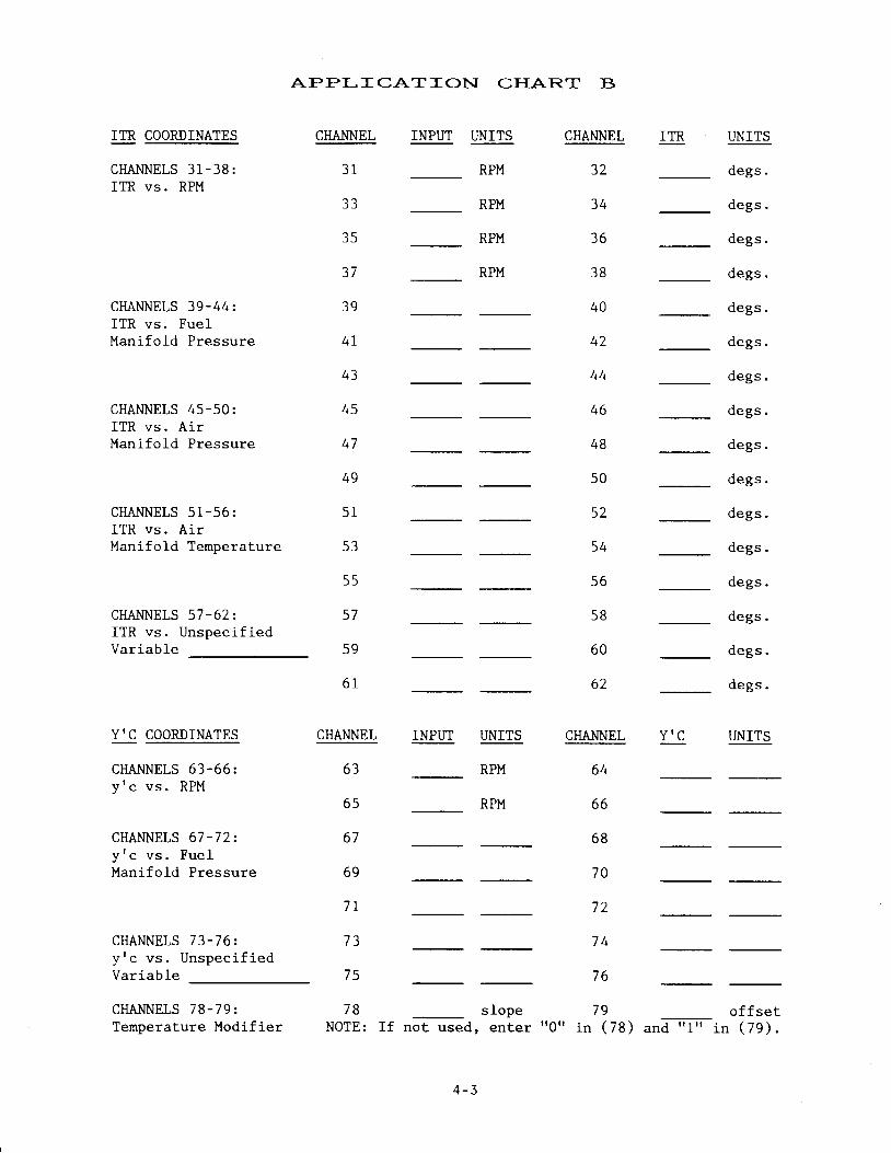
APPI- ICATION CITAR.T B
ITR COORDINATES
CHANNELS 31-38:ITR vs. RPM
CHANNELS 39-44:ITR vs. FuelManifold Pressure
CHANNELS 45-50:ITR vs . A i rManifold Pressure
CHANNELS 51-56:ITR vs . A i rManifold Temperature
CHANNELS 57-622ITR vs. Unspeci f iedVar iable
Y'C COORDINATES
CHANNELS 63-66:y ' c v s . R P M
CHANNELS 67-72:y t c v s . F u e lManifold Pressure
CHANNELS 73-76..y tc vs . Unspec i f iedVariable
CHANNELS 78-792Temperature Modifier
INPUT UNITS
RPM
RPM
RPM
RPM
INPUT T]NITS
RPM
RPM
slopeIf not used, enter
CHANNEL ITR UNITSCHANNEL
31
J J
35
'71
3 9
4 I
4 3
4 l
4 9
5 1
5 3
5 5
5 7
5 9
6 1
CHANNEL
6 2
CHANNEL
d e g s .
d e g s .
d e g s .
d e g s .
d e g s .
d e g s .
degs .
degs .
d e g s .
d e g s .
d e g s .
degs .
d e g s .
degs .
d e g s .
d e g s .
UNITS
32
34
36
3 8
40
42
44
46
48
5 0
5 2
54
5 6
5 8
60
Y I C
6 3
65
6 7
6 9
I T
7 3
7 5
7 8NOTE:
64
6 6
6 8
70
72
7 4
7 6
79 o f fse t' rorr in ( 78 ) a"aTin ( 79 ) .
4 - 3

APPI- ICATION CHAR.T C
CHANNEL NO. ITEM
DTSCRETE OUTPUTS
RPM l imit to tr ip output O/2
RPM l imit to tr ip oulput O/3
82 Time l imir to tr ip output O/4
83 Tirne l imit to tr ip output O/5
84 T ime l im i t to reach RpM (SS; 5 .1ore 0 /6 t r ips
80
6 1
ENTRY UNITS
RPM
RPM
s e c s .
S E C S .
s e c s .
RPM
RPM
8 5
8 6
RPM to be reached wi th in t ime (g4)
Fuel pressure to reach before RpM (g7)before O/7 t r ips
RPM to be reached pr ior to fuel pressure (g6)
Fuel pressure to t r ip output O/g (over load)
RPM to t r ip output O/g (overspeed value)
8 7
8 8
8 9RPM
PI RESPONSE FACTORS
9 2
9 3
94
Reset response rate for fTR
Proportional band value for WGp
Reset response rate for WGp
s e c s .
a
s e c s .
SET-UP CHANNELS
98 No. of sensed teeth or holes
99 password
+ - 4

A. ENTERING THE CONT'IGURATION MODE
- Enter 99 (p ress "9" tw ice) , then- Enter your password, for exampfe- p ress t 'ENTER" :
A11 s ta tus ind ica tors f lash ing ; the
DATA ENTRY
press "ENTER" :"97 69 , ' I
EPC is now in
DISPLAY
[eeE o][ 9 9 E e 7 6 8 ][99 HELLO]
the conf igura t ion mode.
B. ENTER]NG MAGNET]C PICK-UP DATA
- Enter 98 , then press "ENTER" :- Enter the number of gear teeth or holes:NOTE: Maximum number is 500.- p ress t 'ENTER" :
ENTERING ANALOG INPUT SCALING FACTORS
IGNITION TIMING DEGREE SPAN
FUEL PRESSURE
Enter 18 , then press "ENTER" :Enter the total igni t ion degree span to be representedby the 4-20ma cont ro l s igna i :
For A l t ron ic f f -CpU, Memory Code xxxxxx .DA, en ter 4g .0 .For A l t ron ic f I -CpU, Memory Code xxxxxx .DB, en ter 36 .0 .For A l t ron ic f I -CpU, Memory Code xxxxxx .DCj " . , t " .
24 .0 .For A l t ron ic T I_ f -CpU, Memory xxxxxx .CD, en ter 16 .0 o r g .0 .F o r A l t r o n i c C p U - 9 0 , M e m o r y x x x x x x . E E , e n t e r 2 4 . 0 o r 1 6 . 0 .Press "ENTERt ' :
[e8E 0 ][988 xxx]
[e8 xxx]
C .
[ 1 8 E 0 ][ 1 8 E X X . X ]
I ra xx.x ]
Enter 19 , then press "ENTER" :Enter the vol tage input to the EpC represent ing themin imum fue l p ressure o f Channe l 2O ( i .OO tvp i l " f l ,Press "ENTER'| :
Enter 20, then press "ENTERT':Enter the minimum fuel pressure in the desired engineeringunits represented by the vol tage of Channel 20:Press "ENTER":
Enter 21 , then press "ENTER" :Enter the fuel pressure value represent ing5 volts input to the EpC:Press "ENTER,' :
[1eE 0]
l iqn x . )cKl[ 19 x .xx]
[2on 0 ]
[20E x .x ]Qo x .x l
[21r ' o]
[21E xx .x ][2r )o(. x ]
4 - 5

DATA ENTRY
AIR MANIFOLD PRESSURE
- Enter 22, then press "ENTER":- Enter the vol tage input . to the EPC represent ing the
m in imum a i r p ressu re o f Channe l 23 (1 .00 t yp i ca l ) :- Press "ENTER":
- En te r 23 , t hen p ress ! 'ENTER" :- Enter the min imurn a i r pressure in the desi red engineer ing
uni ts represented by the vol tage of Channel 22:- Press "ENTER":
- Enter 24, then press "ENTER":- Enter the a i r mani fo ld pressure value represent ing
5 vol ts input to the EPC:- Press t 'ENTER":
AIR TEMPERATURE
- Enter 25, then press 'TENTER":
- Enter the vol tage input to the EPC represent ing them in imum a i r t empera tu re o f Channe l - 26 (1 .00 t yp i ca l ) :
- Press t tENTERt ' :
- Enter 26, then press "ENTER":- Enter the min imum ai r temp. in the desi red engineer ing
uni ts represent ing the vol tage of Channel 252NOTE: Must enter one d ig i t a f ter the decimal point .
- Press "ENTER' ' :
- Enter 27 , and press 'TENTER":
- Enter the air temperature value representing5 vol ts input to the EPC:
- Press "ENTER":
DISPLAY
l 22E 0 l
l 22E x . ) x l122 X . iC ( l
[ 23E o ]
[ 23E x .X ]123 X .X l
L24E 0l
t24E )C(. X l24 )X .X l
2sE o l
25E X.)Xl25 X. >C( l
26E ol
26E. )O(X.Xl
26 )OO(.X]
27F' ol
[27F' ]Cf i .x lf ^ 1 r ^ r t r ! r l
l L t ] t . A ' . . ^ ' I
UNSPECIFIED ANAIOG INPUT (If Used)
- Enter 28 , and press "ENTER" : [28E 0 ]- Enter the voltage input to the EPC representing the
minimum input value of Channef 29 ( 1.00 typical) : [28E X.)fr ]- Press "ENTER" : [28 X.n ]
- Enter 29 , and press "ENTER' I : [29E 0 ]- Enter the the minimum input value in the desired engi-
neering units represent ing the vol tage of Channel 28: [29E }Cf i .X]NOTE: Must enter one digi t af ter the decimal point.
- Press 'rENTFnrf ; 129 )Cq.X]
- Enter 30, and press rrENTERrr: [30E 0]
- Enter the input value represent ing 5 vol ts input to the EPC: [30E ]OO(.XI- Press trENTERrr: f 30 )OO(.X' I
4 - 6
DATA ENTRY
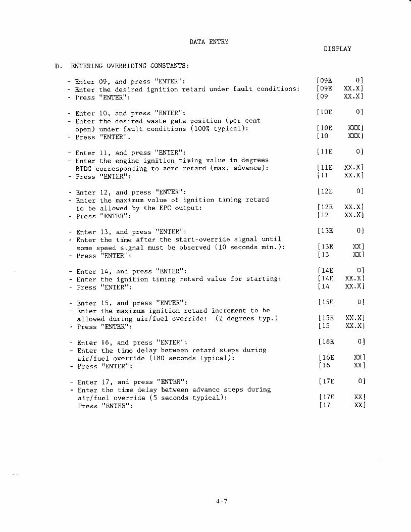
D. ENTERING OVERRIDING CONSTANTS:
- Enter 09, and press "ENTER":- Enter the desired igni t ion retard under faul t condit ions:- Press "ENTER":
Enter 10, and press "ENTER":Enter the desi red waste gateopen) under faul t condi t ionsPress "ENTER":
pos i t i on (pe r cen t( t O O Z t y p i c a l ) :
Enter 11, and press "ENTER":Enter the engine igni t ion t iming value in degrees
BTDC corresponding to zero retard (max. advance):
Press "ENTER":
Enter 12, and press "ENTER":Enter the maximum vaLue of igni-t ion timing retard
to be allowed by the EPC outPut:P ress "ENTERt t :
Enter 13, and press "ENTER":Enter the t ime af ter the star t -overr ide s ignal unt i - l
some speed s igna l mus t be obse rved ( l 0 seconds m in . ) :Press "ENTERt ' :
- EnLer 14, and press "ENTER":- Enter the igni t ion t iming retard value for s tar t ing:- Press t 'ENTERt ' :
Enter 15, and press "ENTERT' :Enter the maximum ignition retard increment to be
al lowed dur ing a i r / fuel overr ide: (2 degrees typ. )Press "ENTER":
Enter 16, and press "ENTER":Enter the tirne delay between retard steps duringa i r / f ue l ove r r i de (180 seconds t yp i ca l ) :Press "ENTER":
Enter 17, and press "ENTER":Enter the time delay between advance steps during
a i r / f ue l ove r r i de (5 seconds t yp i ca l ) :Press "ENTER":
A 1
DISPLAY
09E09En o
0 ln(.x l)c(.xl
10E 0 l
10E no(lro Kfi l
1 1 E
l l E n . x l11 XX .X ]
rzB 0l
rzB n.xl12 )c(.xl
1 3 E
1 3 EI J
0l
)o(l)xl
14E 0 lI4E XX.X ]14 XX.X I
l sE o l
15E p ( .X ll s xx .x l
1 6 8
1 6 E1 6
l 7 E
t7E1 1L I
0 l
ul)il1
0 l
slrc(l
0 l

DATA ENTRY
E. ENTERING THE IGNITION TIMING RETARD AND AIR/FUEL RATIOPERFORMANCE CI"IRVE DATA
IGNITION TIMING RETARD VS. RPM CURVE COORDINATES:
Ente r 31 , and p ress "ENTER" :En te r t he f i r s t RPM con t ro ' po in t ( s l )
for the igni - t ion t iming retard curves:Press "ENTER":
En te r 32 , and p ress "ENTER" :En te r t he va lue o f i gn i t i on t im ing re ta rd ( f f n - s f )
for RPM less than the value of Channel 31:Press "ENTER":
Enter 33, and press "ENTER":Enter the second RPM contro l point (s2)
for the igni t ion t iming retard curves:Press t 'ENTER":
- Enter 34, and press "ENTER":- Enter the value of igni t ion t iming retard ( f fn-sZ)
at the RPM value of Channel 33:- Press "ENTER":
- Enter 35, and press "ENTER":- Enter the third RPM control point (s3)
for the igni t ion t iming retard curves:- Press "ENTER":
DISPlj,Y
[ 31E o ]
L J rtr .\j(JQ( J
[ 31 noo(]
32F, 0
32I' XX.X3 2 ) U . X
a - n nJ J . U U
33E )COC(33 KOfi
34E 0
34E XX.X34 XX.X
35E 0
35E rcOU35 )COfi
- Enter- Enter
at the- Press
36, and press "ENTER":the value of ign i t ion t iming retard ( f tn-s: )
RPM value of Channel 35:. 'ENTER' ' :
[ 368 o ]
36E )X .X l36 )X .X l
37E o l
37F' )OOO(I37 nOO(l
38E 0 l
38E ) f i .X]38 )q .X l
Enter 37, and press "ENTER":Enter the fourth RPM control point (s4)for the igni t ion t i rning retard curves:Press "ENTER":
Enter 38, and press "ENTER":Enter the value of igni t ion t i rning retard ( f fn-sa)at the RPM value of Channel 37:Press t 'ENTER":
4 - 8
DATA ENTRY
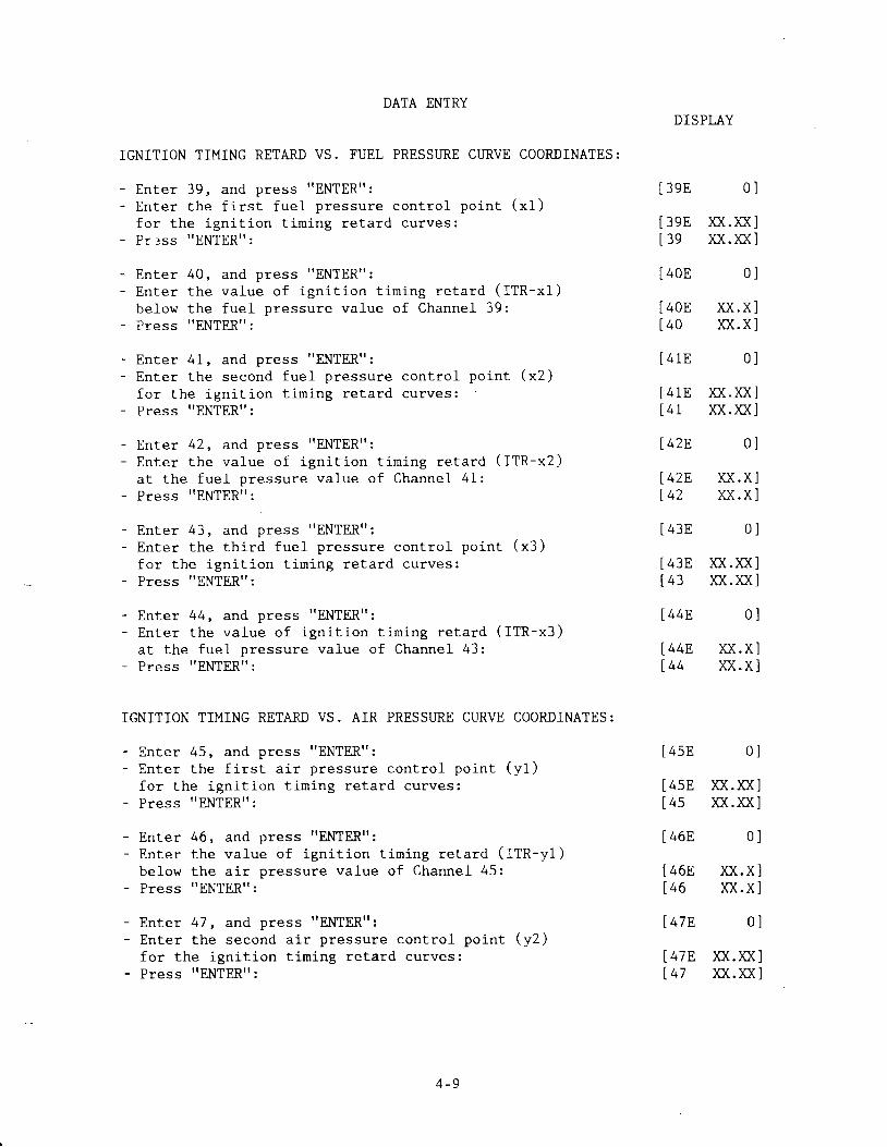
IGNITION TIMING RETARD VS. FUEL PRESSURE CIIRVE COORDINATES:
Enter 39, and press "ENTER":En te r t he f i r s t f ue l p ressu re con t ro l po in t ( x l )
for the igni t ion t i rn ing retard curves:P r : ss "ENTER" :
En te r 40 , and p ress "ENTER" :En te r t he va lue o f i gn i t i on t im ing re ta rd ( f f n - x f )
below the fuel pressure value of Channel 39:Press "ENTER":
Enter 41, and press "ENTER":Enter the second fuel pressure contro l point (x2)
for the igni t ion t iming retard curves:Press "ENTER":
Enter 42, and press "ENTER":Enter the value of ign i t ion t iming retard ( f fn-xZ)
at the fuel pressure value of Channel 41:Press "ENTER":
Enter 43. and Dress "ENTER":En te r t he t h i rd f ue l p ressu re con t ro l po in t ( x3 )
for the igni t ion t iming retard curves:P ress "ENTER" :
Enter 44, and press "ENTER":Enter the value of ign i t ion t iming retard ( f fn-x: )
at the fuel pressure value of Channel 43:Press "ENTERt ' :
IGNITION TIMING RETARD VS. AIR PRESSURE CURVE COORDINATES:
Enter 45, and press "ENTER":En te r t he f i r s t a i r p ressu re con t ro l po in t ( y l )
for the igni t ion t iming retard curves:Press "ENTER":
Enter 46, and press "ENTER":Enter the value of ign i t ion t iming retard ( ITR-y l )
below the a i r pressure value of Channel 45:Press "ENTER":
Enter 47, and press "ENTER":Enter the second a i r pressure contro l point (y2)
for the igni t ion t iming retard curves:Press "ENTER":
DISPLAY
3eE 0 l
39E >o(.)O(l39 >X.)C(l
40E 0 l
40E XX.X I40 xx .x l
[ 41E 0 ]
[41E n( . ]O( l[ 41 n ( . n ]
[42F. 0]
4 3 E 0 l
438 )C(.) f i143 f f . }c( l
44E. 0l
l44E )X.Xl[ 44 ]X .X l
l42E4 L
[ 4sE
[ 4sE[4s
[ 46E
X X . X ]u.x l
0 l
K(.)O(lic(.)fr1
[ 46E ]O(.X146 )f i .X
[ 4 7 8 0
l47E n(.)O([47 ]C(. )O(
. + - J

DATA ENTRY
Enter 48, and press 'TENTER":
Enter the value of ign i t ion t iming retard ( f fn-yZ)
for the a i r pressure value of ChanneL 47;
Press "ENTER. ' :
Enter 49, and press "ENTER":Enter the th i rd a i r pressure contro l point (y3)
for the igni t ion t i rn ing retard curves:Press "ENTERt ' :
Enter 50, and press "ENTER":Enter the value of ign i t ion t iming retard ( ITR-y3)
at the fuel pressure value of Channel 49:
Press 'TENTER":
IGNITION TIMING RETARD VS. AIR TEMPERATI.IRE CURVE COORDINATES:
- Enter 51, and press "ENTER":- Enter the f i rst air temperature control point (z l)
for the igni t ion t iming retard curves:Press t 'ENTERtt:
re ta rd ( f tn -z f )Channel 5l :
DISPI.AY
[ 4 8 E 0 ]
[48E )O( .X ][ 4 8 U . x ]
[4eE o ]
[ 498 ]C(. iO( lf 4e )o(.)o(l
soE o l
50E )O(.Xl50 xx .x l
[ s1E 0 ]
[51E )OO(]ls l )oo(]
[szE o]
szE XX.XIs2 )x .x l
s3E 0 l
s3E nfils3 no(l
s4E 0 l
54E XX.X Is4 n .x l
ssE 0 l
- Enter 52, and press "ENTER":- Enter the value of ign i t ion t iming
below the air temperature value of- Press "ENTER":
- Enter 53, and press "EN[ERtt :- Enter the second a i r temperature contro l point (22)
for the igni t ion t i rn ing retard curves:- Press t .ENTER":
- Enter 54, and press "ENTER":- Enter the value of ign i t ion t iming retard ( fm-zZ)
at the air temperture value of Channel 53:- Press t tENTERt ' :
- Enter 55, and press "ENTER":- Enter the th i rd a i r temperature contro l point (23)
for the igni t ion t i ro ing retard curves:- Press "ENTER":
- Enter 56, and press "ENTER":- Enter the value of ign i t ion t iming retard ( fm-z: )
at the air temperature value of Channel 56:- Press "ENTER":
55E nfflno(lIss
s6E 0 l
s6E )c( .Xls6 )c( .x l
4 - 1 0
DATA ENTRY
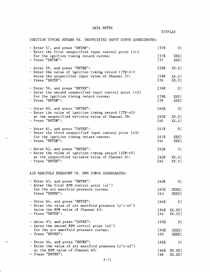
IGNITION TIMING RETARD VS. UNSPECIFIED INPUT CURVE COORDINATES:
Enter 57, and press "ENTER":Enter the f i rs t unspeci f ied input contro l point (v l )for the igni t i -on t iming retard curves:Press "ENTER":
Enter 58, and press "ENTER":Enter the value of ign i t ion t iming retard ( f fn-vf )
below the unspeci f ied input va lue of Channel 57:Press "ENTERt ' :
Enter 59, and press "ENTER":Enter the second unspeci f ied i ,nput contro l point (v2)
for the igni t ion t iming retard curves:Press "ENTER":
Enter 60, and press "ENTER":Enter the value of ign i t ion t iming retard ( f fn-vZ)
at the unspeci f ied var iable value of Channel 59:Press "ENTER":
Enter 61, and press "ENTER":Enter the th i rd unspeci f ied input contro l point (v3)for the igni t ion t iming retard curves:Press t tENTERtt :
Enter 62, and press "ENTER":Enter the value of ign i t ion t iming retard ( f fn-v: )at the unspeci f ied var iable value of Channel 61:Press "EN[ER":
AIR MANIFOLD PRESSURE VS. RPM CURVE COORDINATES:
Enter 63, and press "ENTER":Enter the f i rs t RPM cont ro l po in t (s1 ' )for the air manifold pressure curves:Press t tENTERtt:
Enter 64, and press "ENTER":Enter the va lue o f a i r man i fo ld p ressure (y tc -s1 t )below the RPM value of Channel 63:Press "ENTER":
Enter 65, and press "ENTER":Enter the second RPM control poi .nt (s2')for the air manifold pressure curves:Press "ENTERTI:
Enter 66, and press "ENTER":Enter the va lue o f a i r man i fo ld p ressure (y tc -s2 t )at the RPM value of Channel 65:Press "ENTER":
DISPLAY
[ s7E o ]
[s7E nq][s7 no(]
Is8E p( .x ]
Is8E }o( .x ][ s8 ] x .x l
[ 5 9 E - 0
[598 X]Xt 59 )Ofi
[ 6 0 E 0
[ 6 0 E X X . X[60 ]x . x
[ 6 1 E 0
[ 61E ]OO([ 61 )OO(
[62r' 0
[628 )(X.X[62 ]C( . X
[ 63E 0 ]
[ 63E nOO(][ 63 )OOO(]
[ 64E o ]
[64E K( . ]C( l164 s. )o( l
[ 6sE 0 ]
[6sE noo(]t6s )oofrl
[ 6 6 E 0 ]
[66E xX.n(][66 ]X . )O( l
4- r1

DATA ENTRY
AIR MANIFOLD PRESSURE VS. FUEL PRESSURE CURVE COORDINATES:
- Enter 67, and press "ENTER":- Enter the f i rs t fue l p ressure cont roJ . po in t (x l ' )
for the air manifold pressure curves:Press "ENTERtt:
Enter .68, and press "ENTER" :Enter the value of desired airat the fuel pressure value ofPress "ENTER":
Enter 69, and press "ENTER":Enter the second fueL pressurefor the air manifold pressurePress "ENTER":
DISPLAY
67F. 0l
67F, )C(.)O(l67 XX.)f i ]
m a n i f o l d p r e s s u r e ( y ' c - x l '
Channel 67:
c o n t r o l p o i n t ( x 2 ' )curves:
[ 688
[ 68E[ 6 8
[ 69E
[ 6 9 E[6e
7 0 E
/ U E
70
7IE
7 1 E7 l
72E'
72E,7 2
0 l
) f i .n1xx.)f i1
0
g.) f f
, (A .AI
0
n. )o(u. )G
0
n.)trtr.)fi
0
u.un. )G
Enter 70, and press "ENTER":En te r t he va lue o f des i red a i r man i fo ld p ressu re ( y t c - x2 ' )
at the fuel pressure value of Channel 69:Press "ENTER' ' :
Enter 71, and press "ENTER":En te r t he t h i rd f ue l p ressu re con t ro l po in t ( x3 ' )
for the a i r mani fo ld Dressure curves:Press "ENTER":
Enter 72, and press "ENTERt ' :En te r t he va lue o f des i red a i r man i fo ld p ressu re ( y ' c - x3 ' )
at the fuel pressure value of Channel 71:Press "ENTER"
AIR MANIT'OLD PRXSSI.]RE VS. I.JNSPECIFIED INPUT CIJRVE COORDINATES:
Enter 73, and press "ENTER":Enter the f i rs t unspec i f ied input con t ro l po in t (v1 ' )for the air manifold pressure curves:Press "ENTER":
Enter 74, and press "ENTER":Enter the va lue o f des i red a i r man i fo ld p ressure (y 'c -v l ' )below the unspecif ied input value of Channel 73:Press "ENTER":
Enter 75, and press "ENTER":Enter the second unspecif ied input control point (v2t )for the air manifold pressure curves:
- Press "ENTER":
- Enter 76, and press "ENTER":- Enter the va lue o f des i red a i r man i fo ld p ressure (y 'c -v2 t )
at the unspecif ied input value of Channel 75:- Press .TENTER.' :
[ 7 3 E
[ 7 3 EL I J
L t.+r,
17 4EL t 4
[ 7sE
[ / ) r1L / )
0 l
)o(.)xlxx .n l
0 l
)o(.)xl)c(.nl
0 l
g.XX])x.)ql
0 l
)o(.nl)o(.ul
76E'
76F.7 6
4-12

DATA ENTRY
AIR MANIFOLD PRESSURE - TEMPEMTURE CORRECTION FACTOR:
Enter 78, and press "ENTER":Enter the s lope of the temperature of fset mul t ip l ierf o r a i r man i fo ld p ressu re :
Press "ENTER":
Enter 79, and press "ENTER":Enter the of fset va lue of the Lemperature of fset
mu l t i p l i e r f o r a i r man i fo ld p ressu re :Press t tENTER":
NOTE: I f temperature correct ion is not used,- enter "0t ' in Channel 78- enter "1" i -n Channel 79
F. PID RESPONSE VALUES
Enter 92, and press "ENTER":Enter the Contro l ler response reset t ime value for
i gn i t i on t im lng con t ro l ( 2 sec . sugges ted ) :Press "ENTER' ' :
Enter 93, and press "ENTER":Enter the Contro l ler proport ional band value forwas te ga te con t ro l ( 60 sugges ted ) :Press "ENTER":
Enter 94, and press "ENTER":Enter the Contro l ler response reset t ime value forwas te ga te con t ro l ( 20 sec . sugges ted i n i - t i a l l y ) :Press t 'ENTER":
DISPI.A,Y
7 8 E 0 l
78E 0 . )OO( l78 0 . )OO( l
7 9 E 0
79E U.)f f79 XX.)f i
92F'
928I a ?
I e3E
[ 9 3 8Ie3
[ 94E
[ 94Ef .e4
0 l
x lx l
0 l
XX])o(l
0 l
)c(l)c(l
4 - 1 3

ENTER I/O SEQUENCING FACTORS
- En te r 80 , and- Enter the RPM- P ress "ENTER" :
- E n t e r 8 1 , a n d- Enter the RPM- P ress "ENTER" :
press "ENTER" :t r ip po in t fo r
press "ENTER" :t r i p p o i n t f o r
DATA ENTRY
output channel O/2:
ou tpu t channe l O /3 :
DISPLAY
[ 80E 0 ][808 X)oo(][80 xxxx]
81E 081E )CryX81 >O(XX
8 2 E
82F'8 2
8 3 8
[ 83E[83
I B4E
[ 848[84
XX]XX]
[ 85E o
[85E XXXlss xxx
[ 8 6 8
Enter 82 , and press "ENTER" :Enter the t ime delay from the end of start-overr ideunt i l ou tpu t O/4 t r ips :Press "ENTER" :
Enter 83 , and press "ENTER" :Enter the t ime de lay f rom the end o f s ta r t -over r ideu n t i l o u t p u t O / 5 t r i p s :Press "ENTER" :
Ente r 84 , and p ress "ENTER" :En te r t he t ime f rom the end o f s ta r t -ove r r i de t o a1 lowRPM to reach the va lue o f channe l 85 ( see ou tpu t O /6 ) :P ress "ENTER" :
XXXX
0
?\-?\
XX
Ente r 85 , and p ress "ENTER" :Enter the RPM that must be reachedof Channel 84 af ter the end of the( s e e o u t p u t 0 / 6 ) :P ress "ENTER" :
wi th in t -he t ime val -ues t a r t - o v e r r i d e s i g n a l
En te r 86 , and p ress "ENTER" :Enter the maximum fuel pressure l imi t a t the star t ingspeed o f Channe l 87 ( see ou tpu t O l7 ) :P ress t 'ENTERt ' :
En te r 87 , and p ress "ENTER" :Enter the RPM that must be reached before fuel pressureexceeds the va lue o f Channe l 86 ( see ou tpu t O /7 ) :P ress "ENTER" :
Enter 88 , and press "ENTER" :Enter the maximum fuel manifold pressure al lowed( s e e o u t p u t O / 8 ) :Press "ENTER":
86E8 6
0
XX.XXXX.XX
8 7 E 0
- Enter 89 , and press- Enter the overspeed- Press "ENTERt' :
"ENTER":RPM (see ou tpu t O/B) :
[87E XXX[87 XXX
[ 8 8 E o
[88E XX. ic ([ 88 XX. ]O(
[ 8 9 8 o[898 X]CO([ 89 XX]CK
lll
4 - 1 4

DATA ENTRYDISPLAY
H. LEAVING THE CONFIGUMTION MODE
- Enrer 99: [99 HELLO]- Press "ENTER", then 0: [99E 0]_ p r e s s ' , E N T E R , , : [ 9 9 - - - - - ]
The EPC is now in the nonnal operating mode. Before atternpting full
operat ion on an engine:l. Momentarily interrupt the power and then reconfirm that the data
entries have been retained in the EPC.2. The control funct ion should be simulated ei ther off the engine or
on the engine r,rith no load to be sure the output values are whatare des i red .
4 - 1 5

S E C T I O N 5
OPER.ATION
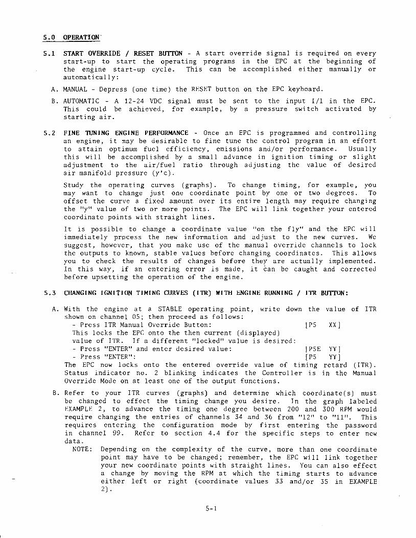
5.0 OPERATION'
5 . 1 START OVERRIDE / RESET BUTTON - A start override signal is required on everystart-up to start the operat ing prograns in the EPC at the beginning ofthe eng ine s ta r t -up cyc le . Th is can be accornp lLshed e i ther nanua l ly o rau tomat ica l 1y :
A. MANUAL - Depress (one t ime) the RESET button on the EPC keyboard.
B. AUTOMATIC - A 12-24 VDC s igna l must be sent to the input I /7 in the EPC.Th is cou ld be ach ieved, fo r exanp le , by a p ressure swi tch ac t iva ted bys t a r t i n g a i r .
5.2 FINE TUNING ENGINE PERFORIT{ANCE - Once an EPC is progranmed and contro l l ingan eng ine , i t may be des i rab le t o f i ne t une the con t ro l p rog ra rn i n an e f f o r tt o a t t a i - n op t imum fue l e f f i c i ency , em iss ions and /o r pe r fo r rnance . Usua l l yth i s w i l l be acconp l i shed by a sna l l advance i n i gn i t i on t im ing o r s l i gh tad jus tmen t t o t he a j , r / f ue l r a t i o t h rough ad jus t i ng t he va lue o f des i reda i r m a n i f o l d p r e s s u r e ( y ' c ) .
S tudy the ope ra t i ng cu rves (g raphs ) . To change t i r n i ng , f o r exanp le , I oumay wan t t o change j us t one coo rd ina te po in t by one o r two deg rees . Toof fset the curve a f ixed anount over i ts ent i re length may requi re changingthe " y t ' va lue o f two o r more po in t s . The EPC w i l l l i nk t oge the r you r en te redc o o r d i n a t e p o i n t s w i t h s t r a i g h t l i n e s .
T r i c nncs i - f l e t o change a coo rd ina te va lue I ' on t he f l y " and the EPC w i l li r uned ia te l y p rpcess the new in fo rma t i on and ad jus t t o t he new cu rves . Wesugges t , howeve r , t ha t you make use o f t he manua l ove r r i de channe l s t o l ockthe ou tpu ts t o known , s tab le va lues be fo re chang ing coo rd ina tes . Th i s a l1owsyou to check the resu l t s o f changes be fo re t hey a re ac tua l l y imp lemen ted .In t h i s w&y , i f an en te r i ng e r ro r i s made , i t t an be caugh t and co r rec tedbe fo re upse t t i ng t he ope ra t i on o f t he eng ine .
5.3 CHANGING IGNITION TIMING CURVES (ITR) I{ITH ENGINE RTINNING / ITR BUTTON:
Wi th t he eng ine a t a STABLE ope ra t i ng po in t , w r i t eshown on channe l 05 ; t hen p roceed as f o l l ows :
- P ress ITR Manua l Ove r r i de Bu t ton :Th i s l ocks t he EPC on to t he then cu r ren t (d i sp layed )
down the value of ITR
I p s
lPs
XX
v a l u e o f I T R . I f a d i f f e r e n t r r l o c k e d " v a l u e i s d e s i r e d :- P ress "ENTER" and en te r des i red va lue :- P r e s s " E N T E R " :
The EPC now locks onto the entered overr ide value of t i rn ingS t a t u s i n d i c a t o r n o . 2 b l i n k i n g i n d i c a t e s t h e C o n t r o l l e r i s
YY
retardin the
( r rR) .Manual
Overr ide Mode on at least one of the output funct ions.
B. Refer to your ITR curves (g raphs) and de termine wh ich coord ina te(s ) nus tbe changed to e f fec t the t in ing change you des i re . In the graph labe ledEXMPLE 2, to advance the t iming one degree between 200 and 300 RPM wouldrequ i re chang ing the en t r ies o f channe ls 34 and 36 f ron "12" to r r11r r . Th isrequ i res en ter ing the conf igura t ion mode by f i rs t en ter ing the passwordin channe l 99 . Refer to sec t ion 4 .4 fo r the spec i f i c s teps to en ter newd a t a .
NOTE: Depending on the complexi ty of the curve, more than one coordinatepoint nay have to be changed; remember, the EPC wi l l l ink togetheryour new coord ina te po in ts w i th s t ra igh t 1 ines . You can a lso e f fec ta change by moving the RPM at which the t i rning starts to advanceeither lef t or r ight (coordinate values 33 and/or 35 in EXAMPLEz l .
5 - 1

C. A f te r t he new da ta i s en te red , check channe l 05 to see i f t he des i red resu l t( 1 I ess deg ree o f ITR i n ou r examp le ) has i ndeed been ach ieved . A t t h i spo in t t he va lue i n channe l 05 i s t he ca l cu la ted ou tpu t t ha t w i l l beinp lemen ted once the Con t ro l l e r i s pu t back on au tona t i c ope ra t i on . Theactual output rernains at the value entered through the manual overr ide but ton.
D. To resume automat ic cont ro l :- Press ITR Manua l Over r ide But ton and "ENTER" :- E n t e r r t 9 9 9 r r '_ P ress r rENTERr r .
The Con t ro l l e r w i l l now resume au tona t i c con t ro l o fus l -ng the new coo rd i . na te va lues tha t have been en te red .
output va lue
5.4 CIIANGTNG ArR/FUEL RATrO (Y'C) r{rTH THE ENGINE RUNNING / l{Gp BUTTON:
A. W i th t he eng ine a t a STABLE ope ra t i ng po in t , w r i t e down the va lues showno n c h a n n e l s 0 6 a n d 0 7 ; t h e n p r o c e e d a s f o l l o w s :
- P ress WGP Manua l Ove r r i de Bu t ton : [P6 XX ]T h i s l o c k s t h e E P C o n t o t h e t h e n c u r r e n t ( d i s p l a y e d )v a l u e o f W a s t e G a t e P o s i t i o n ( W G P ) . I f a d i f f e r e n t" L o c k e d " v a l u e i s d e s i r e d :- P r e s s r r E N T E R r r a n d e n t e r d e s i r e d v a l u e o f W G P :- P r e s s ? t E N T E R [ :
I P 6 Y Y ]The EPC now locks on to t he en te red ove r r i de va lue o f WGP; t ha t i s t he was teg a t e w i l l s t a y a t t h e % - o p e n v a L u e t h a t w a s e n t e r e d ( f o r e x a n p l e , 0 5 e o ) .S t a t u s i n d i c a t o r n o . 2 b l i n k i n g i n d i c a t e s t h e C o n t r o l l e r i s i n t h e M a n u a lOve r r i de Mode on a t l eas t one o f t he ou tpu t f unc t i ons .
Re fe r t o you r a i r p ressu re ( y ' c ) cu rves (g raphs ) and de te r rn ine wh ichcoo rd ina te (s ) mus t be changed to e f f ec t t he a i t / f ue1 ra t j - o change you des i re .
N O T E : T o l e a n t h e n i x t u r e , i n c r e a s e t h e v a l u e o f y ' c .T o r i c h e n t h e r n i x t u r e , d e c r e a s e t h e v a l u e o f y r c .
I n t h e g r a p h l a b e l e d E X A M P L E 1 0 , t o s l i g h t l y l e a n t h e m i x t u r e w o u l d r e q u i r einc reas ing the s lope o f t he cu rve ; f o r exanp le , change channe l 70 f rom 21to 22 . Th i s requ i res en te r i ng t he con f i gu ra t i on mode by f i r s t en te r i ngt h e p a s s w o r d i n c h a n n e l - 9 9 . R e f e r t o s e c t i o n 4 . 4 f o r t h e s p e c i f i c s t e p sto en te r new da ta .
NOTE: Depend ing on the comp lex i t y o f t he cu rve , no re t han one coo rd ina tepo in t may have to be changed ; renember , t he Epc w i l l l i nk you rn e w c o o r d i n a t e p o l n t s t o g e t h e r w i t h s t r a i g h t l i n e s .
C . A f t e r t h e n e w d a t a i s e n t e r e d , c h e c k c h a n n e l 0 7 t o s e e i f t h e d e s i r e d r e s u . l t( s l i gh t t y h ighe r a i r p ressu re i n ou r examp le ) has i ndeed been ach ieved . . Thenc h e c k c h a n n e l 0 6 t o s e e i f t h e W G P p o s i t i o n h a s s l i g h t l y c h a n g e d ( i n o u re x a m p l e , t h e e o - o p € n s h o u l d d e c r e a s e s l i g h t l y ) . T h e v a l u e s i n c h a n n e l . s 0 6and 07 a re t he ca l cu la ted ou tpu t t ha t w i l l be imp lemen ted once the Con t ro l l e ri s pu t back on au to rna t i c ope ra t i on . The ac tua l was te ga te pos i t i on rena insat the val .ue entered through the manual overr ide but ton.
D . To resume au toma t i c con tTo l :- P ress WGP Manua l Ove r r i de Bu t ton and I 'ENTER" :
[ p6E 0 l- E n t e r r ' 9 9 9 r :
[ P 6 E g g g ]- P r e s s I ' E N T E R " : [ 0 6 Z Z ]
The Contro l ler wi l l now resume automat ic contro l o f the WGP outDut valueus ing the new coo rd ina te va lues tha t have been en te red .
I PsEIPsE[0s
t he iTR
09 9 9
Z Z
I P 6 E Y Y ]
5 - 2
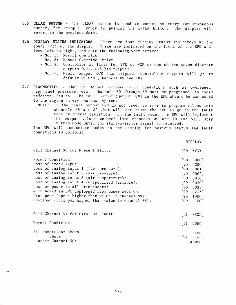
5.5 CLEAR BUTTON - The CLEAR button is used to cancel an entry (an erroneousnumber , fo r : exarnp le ) p r io r to push i .ng the ENTER but ton . The d isp lay w i l trever t to the prev ious da ta .
5.6 DISPL"AY STATUS INDICATORS - There are four d isp lay status indicators at thelower edge o f t he d i sp lay . These a re j , nd i ca ted on the f ron t o f t he EPC and ,f r o m l e f t t o r i g h t , i n d i c a t e t h e f o l l o w i n g w h e n a c t i v e :
- N o . 1- N o . 2- N o . 3
- N o . 4
C a l 1 C h a n n e l 9 0 f o r P r e s e n t S t a t u s
N o r m a l C o n d i t i o n :L o s s o f s p e e d i n p u t :L o s s o f a n a l o g i n p u t 1 ( f u e l p r e s s u r e ) :L o s s o f a n a l o g i n p u t 2 ( a i r p r e s s u r e ) :L o s s o f a n a l o g i n p u t 5 ( a i r t e m p e r a t u r e ) :L o s s o f a n a l o g i n p u t 4 ( u n s p e c i f i e d v a r i a b l e ) :L o s s o f p o w e r t o a l L t r a n s d u c e r s :Ma in boa rd i n EPC unp lugged f rom power sec t i on :O v e r s p e e d ( s p e e d h i g h e r t h a n v a l u e i n c h a n n e l 8 9 ) :O v e r l o a d ( f u e 1 p s i h i g h e r t h a n v a l u e i n c h a n n e l 8 8 ) :
C a 1 1 C h a n n e l 9 1 f o r F i r s t - O u t F a u l t
N o r n a l C o n d i t i o n :
A 1 1 c o n d i t i o n s s h o w nabove
unde r Channe l 90 :
Norrnal operat ionManua l Ove r r i de ac t i veCon t ro l l e r a t l im i t f o r ITR o r WGP o r one o f t he seven d i sc re teo u t p u t s O / 2 - 0 / 8 h a s t r i p p e dFau l t ou tpu t O /8 has t r i pped ; Con t ro l l e r ou tpu ts w i 1 I go t od e f a u l t v a l u e s ( C h a n n e L s 0 9 a n d 1 0 1
5 .7 D IAGNOSTICS - The EPC senses va r i ous fau l t cond r t i ons such as ove rspeed ,h igh fue l p ressu re , e t c . Channe l s 80 th rough 89 mus t be p rog ramned to avo idundes i red fau l t s . The fau l t ou tpu t (O .u tpu t 0 /8 ) i n t he EPC shou ld be connec tedto t he eng ine sa fe t y shu tdown sys ten .
NOTE: I f t he f au l t ou tpu t O /8 i s no t used , be su re t o p rog ram va lues i n tochanne l s 88 and 89 tha t w i l l no t cause the EPC to go to t he f au l tmode i n no rna l ope ra t i on . I n t he f au l t mode , t he EPC w i l l impJ .emen tthe ou tpu t va lues en te red i n to channe l s 09 and 10 and w i l l s t ayj . n t h i s m o d e u n t i l t h e s t a r t - o v e r r i d e s i g n a l i s r e c e i v e d .
The EPC w i l l annunc ia te codes on the d i sp lay f o r va r i ous s ta tus and fau l tc o n d i t i o n s a s f o l l o w s :
D I SPLAY
[90 xxxx
9 0 0 0 0 09 0 0 2 0 09 0 0 0 0 19 0 0 0 0 29 0 0 0 1 09 0 0 0 2 09 0 0 0 3 39 0 0 2 3 39 0 1 0 0 09 0 0 1 0 0
9 1
9 1
9 1
XXXX
0 0 0 0
samea s
above

S E C T I O N 6
INSTAI - I -ATION

6.0 INSTALLATION
6.1 GENEML INSTALLATION LAYO{JT - Refer to figure 3 for the general layout ofw i r ing in and ou t o f the EPC-200C Cont ro l le r .
6-2 MOLJNTING TIIE EPC - The EPC is preferably panel-mounted off the engine insuch a manner as to min imize exposure to v ib ra t ion . Refer to f igure 4 fo rp h y s i c a l n o u n t i n g d e t a i l s .
6.3 OPERATING ENVIRONMENT - Operat ing tenperature range is 32" to 158" F. /0 " t o 7 0 ' C . H u m i d i t y s p e c l f i c a t i o n i s 0 - 9 5 % , n o n - c o n d e n s i n g .
6.4 PART NO. DESIGITIATION - The electr ical rat ing of var ious parts of the EPCc o n t r o l l e r i s d e s i g n a t e d i n t h e f u l 1 d e v i c e P a r t N o . w h i c h i s f o u n d o n t h ei n s i d e o f t h e e n c l o s u r e .
EXAMPLL: EPC - 200Cm - xym = Le t te r des ignat ing the requ i red Power Source :
A = 110 VAC, D = 24 VDCx = Number des ignat ing Input l " lodu le type :
1 = I D C 5 m o d u l e : 7 0 - 3 2 V D C - w h i t e c a s e2 = I A C 5 m o d u l e : 9 0 - 1 4 0 V A C / D C - y e l l o w c a s e
y = Nunber des ignat ing Output l r lodu le type :4 = 0 D C 5 m o d u l e : 6 0 V D C , 2 A . - r e d c a s e5 = O A C 5 A n o d u l e : 2 4 - 2 8 0 V A C , 2 A . - b l a c k c a s e6 = O D C S A r n o d u l e : 5 - 2 0 0 V D C , 0 . 6 7 A . - r e d c a s e
6.5 ELECTRdCAL IIOOK-UP - GENERALA. The power connect ions to the EPC-200C must be in accordance w i th the Nat iona l
E l e c t r i c a l C o d e . T h e E P C - 2 0 0 C i s s u i t a b l e f o r i n s t a l l a t i o n i n C l a s s I ,D i v i s i o n 2 l o c a t i o n s . T h e e x t e r n a l p o w e r i s c o n n e c t e d t o t h e E P C p l u s ( * )a n d m i n u s ( - ) c o n n e c t i o n s ( s e e f i g u r e 5 ) ; t h e G r o u n d t e r m i n a l i n t h e E P Cnust be connected to ear th g round wh ich may be the same as the power negat ive( - ) . The input power has a 3 -amp pro tec t ive fuse . The EPC can be poweredi n o n e o f t h e f o l l o w i n g w a y s :1 . 24 VDC POWERED MODELS:
- 2 4 v o l t b a t t e r y w i t h t r i c k l e c h a r g e r ( 2 a m p m i n . c a p a b i l i t y ) ;- D C p o w e r s u p p l y c a p a b l e o f f u r n i s h i n g 1 8 - 3 6 V D C , 5 a m p s .
2 . 1 1 0 V A C P O W E R E D M O D E L S :- A source o f " ins t ru rnent qua l i t y " 110-120 VAC f ree f ro rn l ine sp ikes
s u c h a s c a u s e d b y t h e t u r n i n g - o n o f e l e c t T i c m o t o r s , e t c .NOTE: Vo l tage and cur ren t supp l ied must be su f f i c ien t to opera te a l I
t r a n s d u c e r s u s e d i n t h e i n s t a l l a t i o n .
B. A separa te 24 VDC Ins t rument Supp ly i s ava i lab le in the EPC as a power sourcef o r t h e a n a l o g i n p u t t r a n s d u c e r s . T h i s o u t p u t i s p r o t e c t e d w i t h a 0 . 5 - a m pf u s e .
C. Power w i r ing and s igna l ( t ransducer ) w i r ing must be in separa te condu i tsand condu i - t en t r ies in to the EPC to avo id undes i red e lec t r i ca l in te rac t ion .S e p a r a t e a s f o l l o w s ( s e e f i g u r e 3 ) :1 . R5422 Communica t ions Wi r ing .2 . S igna l Wi r ing : magnet ic p ick -up , ana log i -nputs , 4 -20 ma ana log ou tpu ts ,
+ / - 24YDC ins t rument power .N O T E : U s e # 2 4 A W G , . 0 3 2 1 t i n s u l a t e d h o o k - u p w i r e ( U . L . s t y l e 1 0 1 5 o r
A l t ron ic par t no . 603 I02 or 603 103) fo r the s igna l connect ionsbetween the EPC and engine rnounted transducers.
3 . Power Wi r ing : inpu t power , inpu t nodu le I /1 , ou tpu t nodu les O/2 -O/8 .
6 - 1

D. The analog inputs of the EPC operate with var ious types of t ransducerso u t p u t t i n g 4 - 2 0 m a ( 1 - 5 V . ) . F i g u r e s 7 , 8 a n d 9 s h o w w i r i n g d i a g r a m s u s i n gtypical types of input transducers and output connect ions to an AltronicI I -CPU or I I I -CPU ign i t ion sys tem and to the pressure t ransducer fo r thew a s t e - g a t e .NOTE: A11 input cornmons are to be re fe renced to te rn ina l #40. Do NOT
use te rmina l #20 Q2 V, ) to power any ex terna l dev ices except asshown in f i o t t re . '7 , R or 9 .
tr T h e I n p u t M o d u l e I / 1 ( n a s t e r r e s e t ) i s p r o t e c t e d w i t h a 3 - a r n p f u s e . I ti s necessa ry t o impose a vo l t age w i th in t he ra t i ng o f t he pa r t i cu la r modu leu s e d ( s e e s e c t i o n 6 . 4 a b o v e ) t o e f f e c t a r e s e t c o n d i t i o n . T h e k e y b o a r dRESET bu t ton a l so p rov ides the same func t i on .
T h e s o l i d s t a t e D C o u t p u t m o d u l e s ( O / 2 a n d O / 8 ) h a v e t h e f o l l o w i n g a s s o c i a t e dw i t h e a c h d e v i c e ( s e e s e c t i o n 6 . 4 f o r e l e c t r i c a l r a t i n g s ) :- a n L E D i n d i c a t o r m o u n t e d d i r e c t l y a b o v e i t s a s s o c i a t e d s o l i d s t a t e r e l a y ;
t h e o u t p u t s w i t c h i s i n t h e c l o s e d p o s i t i o n w h e n t h e L E D i s o n .- a 3 -amp fuse i n t he ou tpu t 1eg moun ted on the c i r cu i t boa rd d i rec t l y
b e l o w i t s a s s o c i a t e d s o l i d s t a t e r e 1 a y .A t yp i ca l au toma t i c s ta r t hook -up us ing a l l seven ou tpu t modu les i s showni n f i g u r e 6 .
A 1 1 t e r m i n a t i o n s t o t h e E P C a r e t o p l u g - i n t y p e t e r m i n a l s t r i p s ; t h e s er e q u i r e o n l y t h a t t h e w i r e i n s u l a t i o n b e s t r i p p e d b a c k a p p r o x i n a t e l y I / 4 " .A sma11 sc rewdr i ve r i s used to secu re t he conduc to r t o t he p lug - i n connec to r .The p lug - i n connec to rs mus t be l i f t ed away f rom the bo t tom o f t he box fo rre rnova l .
6 - 2

FIG.3
GENERAL INSTALLATION LAYOUT
tPCUNIT
RS_422 COMMUNICATI (
S P E E
) N S
) PULSES
FUEL PS i
W
L_=_ __ValuNCTlONS
W.G. CONTROL I , , ^ ISTATION AIR
A I R P S I
4 2OmA
TEMP. TRANS._l Jo PSr
J _ 1 5 P S ICPU 4 2OmA
M A C N E T I CP I C K U P
I LYWHEEL
L:f:l
r-n IA
L \i t
GI NI
CPU
tz'/
F U N C T I O N E P C T E R M I N A L N O .
M A G N E T I C P I C K U P r ( + ) & 2 ( - )FUIL PRTSSURE TRANSDUCER 8 & 9
AIR PRESSURT TRANSDUCER 1 0 & ' l 1
CPU CONTROL SIGNAL 1 6 ( - ) & 1 7 ( + )TEMPERATURE TRANSMITTER 1 2 & 1 J ( S E E W t R t N G D T A G R A M )
I /P CONVERTER SIGNAL 1 B& 1 9
MANUAL, /REMOTE START SWITCH 2 0 & . 2 5r /o FUNCTTONS 26 THRU 39
INSTRUMTNT (+24V) 20
COMMON 40
STATION POWER + t + l
STATION POWER _ )
6 - 3

FIG.4
EPC MOUNTING DIMENSIONS
II
. 2 5 7 D I A(4 TOTAL)
1 2 . 1 8 1 J . 5 3
/ ' l t I/ l 2oo 1200 1 I
/ r<!-l<.Di
I/_ l/ i I . ; - ro 1 . 4 7
L," , ,o coNDUrrENTRY (3 TOIAL)
N O T [ : P A N E L C U T - O U T I S 1 0 . 1 2 XA L L D I M E N S I O N S I N I N C H T S
1 2 . 1 2
U L J I - J \ , L J
OOt]ODI]DOt]O
DD
6 - 4

6.5 TERUINAL STRIP DESIGI{ATION (See figure 5)
TERMINAL NO.
l-
2
4q
67
d
v1011I2' J
), t+
1 5
1 67 71 81 9
2 04 0
) 1
2 22 3
2 42 52 6/ t
2 82 93 03 13 23 3J 4
3 53 63 73 85 9
+
bround symDol
FUNCTION
Magnetj-c Pick-upMagnet ic P ick -upSh ie ld - Mag. P ick -up
RS-422 - XMARS-422 - XMBRS-422 . REC. ARS-422 - REC. B
AnalogAnalogAna logAnalogAnaIogAnalogAna logAna log
i n p u t l ( x ) - n e g a t i v ei n p u t l ( x ) - p o s i t i v ei n p u t 2 ( y ) - n e g a t i v ei n p u t 2 ( y ) - p o s i t i v ei n p u t 3 ( z ) - n e g a t i v ei n p u t 3 ( z ) - p o s i t i v ei n p u t 4 ( v ) - n e g a t i v ei n p u t 4 ( v ) - p o s i t i v e
( - )( * )( - )( * )t -( +
t -( +
Ign i t ion t in ing ou tpu t - negat ive ( -I g n i t i o n t i m i n g o u t p u t - p o s i t i v e ( +A i r / fue l ra t io ou tpu t - negat ive ( - )A i r / fue l ra t j -o ou tpu t - pos i t i ve (+)
Ins t rument 24VDC power -Ins t runent 24VDC Dower -
Not usedN o t u s e dNot used
D i g i t a l i n p u t 1 -D i g i t a l i n p u t 1 -D i g i t a l o u t p u t 2 -D i g i t a l o u t p u t 2 -D i g i t a l o u t p u t 3 -D i g i t a l o u t p u t 3 -D i g i t a l o u t p u t 4 -D i g i t a l o u t p u t 4 -D i g i t a l o u t p u t 5 -D i g i t a l . o u t p u t 5 -D i g i t a l o u t p u t 6 -D i g i t a l o u t p u t 6 -D i g i t a l o u t p u t 7 -D i g i t a l o u t p u t 7 -D i g i t a l o u t p u t 8 -D i g i t a l o u t p u t 8 -
pos i t j - venega t ] . ve
n e g a t i v e ( -p o s i t i v e ( +n e g a t i v e ( -p o s i t i v e ( +nega t l , ve ( -
p o s J . t i v e ( +n e g a t i v e ( -p o s i t i v e ( +n e g a t i v e ( -p o s i t i v e ( +n e g a t i v e ( -p o s i t i v e ( * )n e g a t i v e ( -p o s i t i v e ( +n e g a t i v e ( -p o s i t i v e ( +
t +
t -
Input powerInput powerGround
p o s i t i v e ( * )n e g a t i v e ( - )
fo r DC mode lsfo r DC mode ls
6 - 5

- NOf\v\ocr- o Ind lno- " lv l lSrc
9Io
O C ;n f fv <
q ! .
l c rr t Z
L c->I r l Z
ooaF
J
(Jc ) a> o _r ) <I
@ l . .
: snJ u lMod lndNr
: S N J 1 N ] A N U I S N I
u lMod lndNr
+ / lnd lno- - l v l l 9 l c- ^ lfl"llno- ' - rv l rc rc
+ "
lndIno- = l v l l c lc l- Jndrno- o r v t t c t c-
" l nd lno
- ' lv-Llclcl. , lndlno- " tv |c tc* , l n d N t* ' t v l t S r c l
+ lnd tno- 0r1vu Inl/urv+ 1ndln0 cN[\11- N O r t r N 3 l+ rndN l- o corvNV+
c l n d N l- - 30 t vNV
+ z l n d N l
- " co lvNV* , l n d N l- , S O I V N V
|) C' I ] IHS
U )J J d
N =^ - . , ( \ l =J l i l q - $. , t =x u r 3
M >Y
* O, . O
V
BrV A
d n ) 3 r d
t - A ll v l
lotto lt v l
E
tl[o-]lolleltG l
le Ilelt a ll v l
lelte Ilelle Ilelleltollellelle Ilolleltol
F:f
IqjgJTL
z=EIUF
eeoooeeooooooeooeoo
6 - 6

FIG.6
1 2 - 2 4 V d c O R
RESET
STOP
START
C R 1 * F A U L T
OPTN @l O O R P M
o2
a ^ a 1J t J /
C R A N K I N GAIR
I G N I T I O Nfo
C L O S I @ 1 2 S E C
32
CLOSE @ 2OO RPM
STARTINGF U E L
R U N N I N GF U E L
i " , OPEN ON FAULT+.
3 9 ' 4 t J 8
1 0Oo C R 2
i--aI G N I T I O NSHUTDOWN L IAD
N O T t :
1 . *FAULT CONTACT FROM CUSTOiVtR SAFETy SHUTDOWN SYSTEM.
2. CRl AND CR2 ALTRONTC p /N 61 O 064_24 FOR 24vDC SYSTEM.
3. T IMI AND SPEED SETTINGS ARE PROGRAMIVABLE FROM THE KEYPAD ON THE FRONT PANEL.
4 . CONTACTS 06 AND 07 ARE TYPICALLY USED FOR OVERCRANKAND FLOODED ON START UP.
OPEN @ 5 SEC
6 - 7

-l[. 0Nl-l0UD
U3At ]d INdNI
EE
lo_(-)(--)ZCuI
o_l>Z(J
L
('.)Ft-!Zt3{
F:)o
I
\ JqJLL
z
EutF
d] I I IhSNVd.Ll d n l v d f d h l r
d l f ,n [sNVdlf d n s s l d d d I V
d ] ] N [ S N V d Il d n s s l d d l l n j
d f ] N O S N V d IlN fdun l
- / l dnss ldd
oSSSSsSSSSSSSSSSSSSS
SSSSSSSSSSSSsSesSSSS
S c 1
6 - 8

0 N n D d !
d l A [ d l n d N l
u0ga
[]
tll
3(-J
7!uF_J
o-l:ZCJ
il
F
ZL'{
l--:)o
I
qjgJlr
z
ccUJF
d ] I I I h S N V d Il d n l v d l d N l l
d ] I 1 I h S N V d ll d n s s l d d d I V
d l 1 l l t ' l s N V d tl dnss ldd l l n r
d l l n 0 s N V d l_ IN lddnf
+H- U r t dnss fdd
SSSSSSSSSSSSSSssSSSS
SSSSsSsSsSSSssSSSSSS
o - v

l0*(J
(J
Zflu__){
ol
;L
=F
Zt_f{z
d ] I - I I h S N V d Il d n l v d l d t 4 l r
d l 1 l i h s N V d Il d n s s l d d d I V
d ] I l I h S N V d ll d n s s l d d l l n _ i
INnId !
d l A [ d l n d N ]
UOEZ
Et_l
O
o'ctomr-rc)
\ocr)
lf)Cf)
ct
c.)C'
tuc.)
cr)
Ffo
I
\r) |
gJTL
z
cctuF-
d l l n 0 s N V d ll N l d d n f
0 r l d n s s t d d
SSSSsSSSsSSsSesSSSSS
SSSSSSSSSSSSSSSSSSSS
Oc\lo'
CD
N
\D
a
cr)
c\l
O
o\
co
F.
\o
U)
c')
CU
ocro\CUcoCUl--CU\o.Ur-r)CU
CUctCUrUCU
CU
6 - 1 0

S E C T I O N 7
P A R : T S L I S T

PARTS IDENTIFICATION FrG.10
/rI . - j
.lii'-tli+# I' i i- '
/ -
/.,j,/@@@@@@@@@@ta-----tr (--n r-l a-l r.-ll l . l l l l x N s l l l l R r s r l l l l d { l l l l a r l l
trlfrontc'EPC rNctNE PERFoRMANCE coNTRoLLER
o l o o o o o o o
! 00 [ ! 000
a
a
a
o
1 1

7.0 PARTS LIST - EPC-2OOC
FIGURE 6R E F . N O .
_t u- _t- \ a- t D
- t o- 1 e
1 t- a l
- l o- 1 n
- l ' i
- 1 K
- 3A
- q
- 6- 7
- 8- 9- 1 0- 1 1
- 1 1 a- 1 1 b- 1 1 c- 1 1 d
- 1 1 e- 1 1 f-72
-13
1 A- a +
- 1 5- 1 6
PART NO.
6 1 0 2 3 06 1 0 2 2 16 7 0 2 5 62 1 0 6 2 s9 0 2 5 9 96L0 2r96 1 0 2 2 0902 43961.0 2576 1 0 1 6 66 0 2 3 0 0610 216
6 7 0 2 2 7902 4596 1 0 2 0 9
DESCRI PTI ON
Enc losureP l a t e , e n t r yGrommetG a s k e tS c r e w I 0 - 2 4 n y l o cMount ing bar - hor izon ta lMount ing bar - ver t i ca lS c r e w 1 0 - 3 2C a b l e c l a m p , r i b b o n c a b l eT ie anchorLabe l - S /NKeypad
602 283 -1 F rane902 s78902 617610 443
S c r e w 4 - 4 0S c r e w I 0 - 3 20- r ing
Standof f , a luminumL o c k - n u t 6 - 3 2Jumper cable
6 7 2 0 8 1 - E P C L o g i c b o a r d a s s e m b l y6 0 1 4 7 1 - E P C M e m o r y c h i n
6 1 0 2 4 36 1 0 2 4 r6 0 2 3 7 26 0 2 2 9 46 0 2 2 9 76 0 2 3 0 36 1 0 2 2 89 0 2 s 9 86 9 1 0 5 76 9 1 0 6 46 9 1 0 5 66 9 1 0 6 56 9 1 0 6 66 1 0 2 5 4902 4396 1 0 1 4 5
6 8 1 0 3 3 - 1 I / O b o a r d a s s e m b l y , E P C - 2 0 0 C F , I 2 V D C6 8 1 0 3 3 - 2 I / 0 b o a r d a s s e m b l y , E P C - 2 0 0 C D , 2 4 V D C6 8 1 0 3 3 - 3 I / O b o a r d a s s e r n b l y , E P C - 2 0 0 C A , 1 1 S V A C
R e c e p t a c l e p l u g , 2 0 - p o s i t i o nR e c e p t a c l e p l u g , 3 - p o s i t i o nLabe l - p lug te rmina lL a b e l , E P C - 2 0 0 C F , I 2 V D CL a b e 1 , E P C - 2 0 0 C D , 2 4 V D CL a b e 1 , E P C - 2 0 0 C A , 1 1 5 V A CStandoff , aluminumScrew 6-32Input nodu le IDC5Input modu le IACSOutput module ODCSOutput module 0AC5AOutput module ODCSAS t a n d o f f I 0 - 3 2 ( E P C - 2 0 0 C A o n l y )S c r e w I 0 - 3 2C a b l e t i e
7 - 2