Embed Size (px)
Citation preview

Series TFXL
Transit Time Ultrasonic Flow Meter
Remote Mount System
Operations & Maintenance Manual
REV 8/08


Rev. 8/08 -1.1- TFXL-X
TABLE OF CONTENTS
Pages Quick-Start Operating Instructions 1.3 - 1.4 Introduction General 1.5 Applications 1.5 Model Matrix 1.6 Product Specifications 1.7 Components and Terminology 1.8 Transmitter Connections Transmitter Limits and Installation 1.9 Power and Transducer Connections 1.10 - 1.12 Input/Output Connections and Options 4-20 mA Output 1.13 - 1.14 Pulse Output 1.15 - 1.16 Application of Power and Troubleshooting 1.17 - 1.18 Transducer Mounting Mounting Location 2.1 - 2.2 Transducer Mounting Method 2.3 - 2.6 Transducer Spacing, Pipe Preparation and 2.7 - 2.15 Mounting Transducer Mounting Rail 2.16 - 2.17
Part 1 - Introduction
Part 1 - Connections
Part 1 - Inputs and Outputs
Part 2 - Transducer Installation

Rev. 8/08 -1.2- TFXL-X
TABLE OF CONTENTS
Pages Software Utility Operation Programming Entries General Programming Information 3.1 - 3.2 BASIC MENU 3.3 FLOW MENU 3.4 - 3.6 ADVANCED MENU 3.7 - 3.8 OUTPUT MENU 3.9 - 3.10 DISPLAY MENU 3.11 Flow Meter Calibration 3.12 - 3.14
Appendix
Fluid Characteristic Table TFX Error Codes Pipe Dimension Chart: Cast Iron
Pipe Dimension Chart: ST, SS, PVC Velocity to Volumetric Conversion Statement of Warranty
Customer Service
Hazardous Area Installation Drawing
Pipe Dimension Chart: Ductile Iron
General Terms and Conditions
Part 3 - Programming
Appendix

Rev. 8/08 -1.3- TFXL-X
This manual contains detailed operating instructions for all aspects of the TFXL instrument. The following condensed instructions are provided to assist the operator in getting the instrument started up and running as quickly as possible. This pertains to basic operation only. If specific instrument features are to be used or if the installer is unfamiliar with this type of instrument, refer to the appropriate section in the manual for complete details. 1. TRANSDUCER LOCATION
A. In general, select a mounting location on the piping system with a minimum of 10 pipe diameters (10 × the pipe inside diameter) of straight pipe upstream and 5 straight diameters downsteam. The installation location should also be positioned so that the pipe remains full when the liquid is flowing through it. On horizontal pipes the transducers should be located on the sides of the pipe. See Figure 1.2 on page 1.4. See Table 2.1 on page 2.3 for additional configurations.
B. Select a mounting method, Figure 1.1, for the transducers from Table 2.2 on page 2.5, based on pipe size and liquid characteristics. In general, select W-Mount for plastic and steel pipes flowing clean, non-aerated liquids in the 1-6 inch (25-150 mm) internal diameter range. Select V-Mount for pipes of all materials and most liquids in pipe sizes from 3-16 inches (75-400 mm). Select Z-Mount for pipes larger than 16 inches (400 mm).
C. Enter the parameters listed in Table 1.1 via the TFXL ULTRALINK™ software utility.
D. Record the value calculated and displayed as Transducer Spacing.
Transducer Location
QUICK-START OPERATING INSTRUCTIONS
W-Mount V-Mount Z-Mount
Figure 1.1 Transducer Mounting Configurations

Rev. 8/08 -1.4- TFXL-X
2. PIPE PREPARATION AND TRANSDUCER MOUNTING A. The piping surface, where the transducers are to be
mounted, needs to be clean and dry. Remove loose scale, rust and paint to ensure satisfactory acoustical bonds.
B. Apply a 1/4" (6 mm) wide bead of couplant, lengthwise onto the transducer faces. Place the single DTTS/DTTC transducer or each DTTN/DTTH transducers onto the pipe ensuring proper linear and radial placement.
C. Tighten the transducer mounting straps sufficiently to squeeze the couplant out along the flat surface of the transducer, filling the void between the transducer and the pipe wall. Small pipe transducers using wing nuts should be hand tightened only.
3. TRANSDUCER/POWER CONNECTIONS A. If additional cable is to be added to the transducers, utilize
RG59 coaxial cable and ensure that both cables are of equal length.
B. Refer to the wiring diagram located on the inside of the TFXL cover and Figure 1.4 on page 1.10 for proper power and transducer connections. Verify that the voltage level listed on the product identification label - located on the side of the instrument enclosure - matches the power source where connection is being made.
4. INITIAL SETTINGS AND POWER UP A. Apply power to the instrument. B. Verify that SIG STR is greater than 2%. C. Verify that measured liquid SSPD is within 0.5% of the
configuration value. D. Input proper units of measure and I/O data.
Startup
Connections
QUICK-START OPERATING INSTRUCTIONS
Figure 1.2 Transducer Orientation
Table 1.1 1. Transducer mounting method 2. Pipe O.D. (outside diameter) 3. Pipe wall thickness 4. Pipe material 5. Pipe sound speed¹ 6. Pipe relative roughness¹
7. Pipe liner thickness 8. Pipe liner material 9. Fluid type 10. Fluid sound speed¹ 11. Fluid viscosity¹ 12. Fluid specific gravity¹
¹ Nominal values for these parameters are included within the TFXL operating system. The nominal values may be used as they appear or may be modified if exact system values are known.
Rev. 8/08 -1.5- TFXL-X
PART 1 - INTRODUCTION
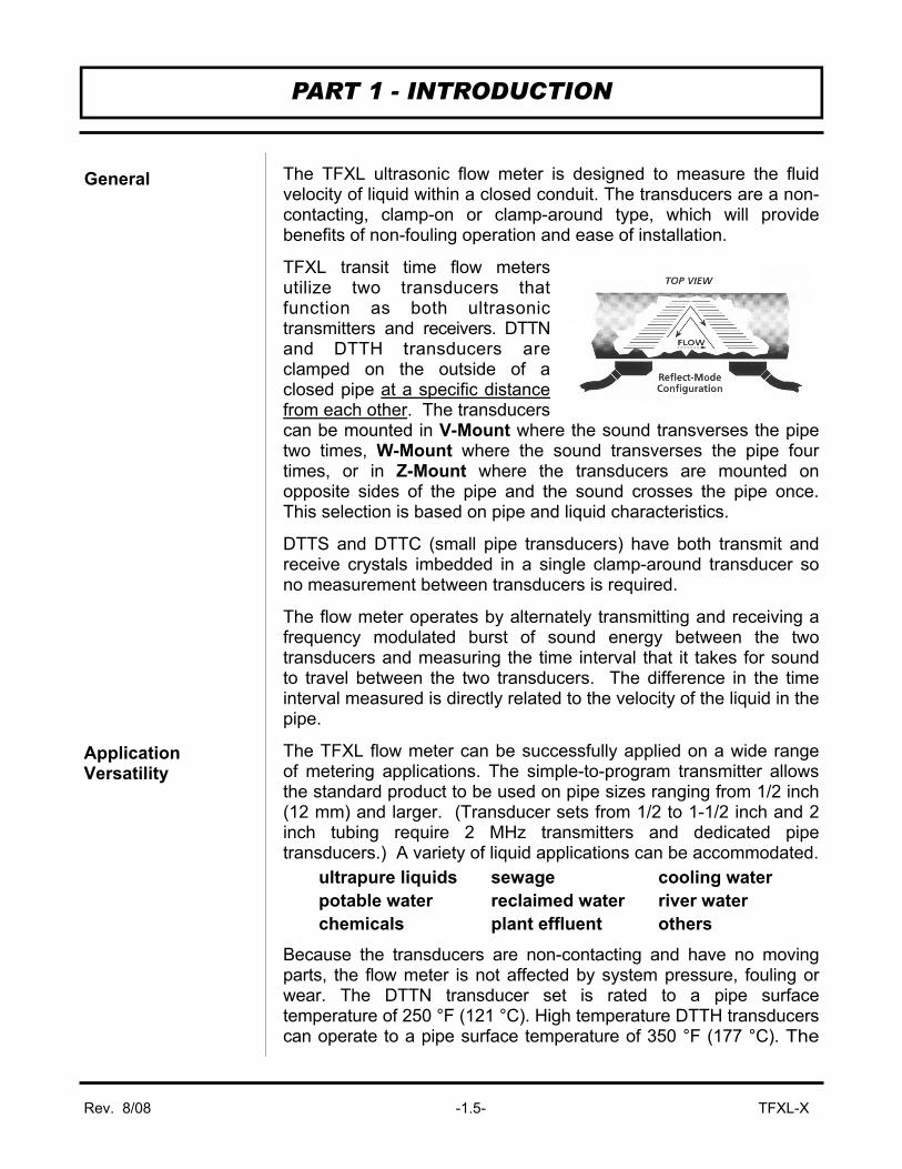
The TFXL ultrasonic flow meter is designed to measure the fluid velocity of liquid within a closed conduit. The transducers are a non-contacting, clamp-on or clamp-around type, which will provide benefits of non-fouling operation and ease of installation.
TFXL transit time flow meters utilize two transducers that function as both ultrasonic transmitters and receivers. DTTN and DTTH transducers are clamped on the outside of a closed pipe at a specific distance from each other. The transducers can be mounted in V-Mount where the sound transverses the pipe two times, W-Mount where the sound transverses the pipe four times, or in Z-Mount where the transducers are mounted on opposite sides of the pipe and the sound crosses the pipe once. This selection is based on pipe and liquid characteristics.
DTTS and DTTC (small pipe transducers) have both transmit and receive crystals imbedded in a single clamp-around transducer so no measurement between transducers is required.
The flow meter operates by alternately transmitting and receiving a frequency modulated burst of sound energy between the two transducers and measuring the time interval that it takes for sound to travel between the two transducers. The difference in the time interval measured is directly related to the velocity of the liquid in the pipe.
The TFXL flow meter can be successfully applied on a wide range of metering applications. The simple-to-program transmitter allows the standard product to be used on pipe sizes ranging from 1/2 inch (12 mm) and larger. (Transducer sets from 1/2 to 1-1/2 inch and 2 inch tubing require 2 MHz transmitters and dedicated pipe transducers.) A variety of liquid applications can be accommodated. Because the transducers are non-contacting and have no moving parts, the flow meter is not affected by system pressure, fouling or wear. The DTTN transducer set is rated to a pipe surface temperature of 250 °F (121 °C). High temperature DTTH transducers can operate to a pipe surface temperature of 350 °F (177 °C). The
General
Application Versatility
ultrapure liquids sewage cooling water potable water reclaimed water river water chemicals plant effluent others
Rev. 8/08 -1.6- TFXL-X
PART 1 - INTRODUCTION
DTTS small pipe transducers can be used to a pipe surface temperature of 185 °F (85 °C) and the DTTC high temperature small pipe transducers are rated for 250 °F (121 °C).
The TFXL uses a low voltage DC power source that provides electrical safety for the user. Removing the cover allows access to all the meter connections and the computer interface connection.
Non-volatile flash memory retains all user-entered configuration values in memory indefinitely, even if power is lost or turned off.
The serial number and complete model number of each TFXL are located on the side of the instrument enclosure. Should technical assistance be required, please provide the Dynasonics Customer Service Department with this information.
User Safety
Data Integrity
Product Identification
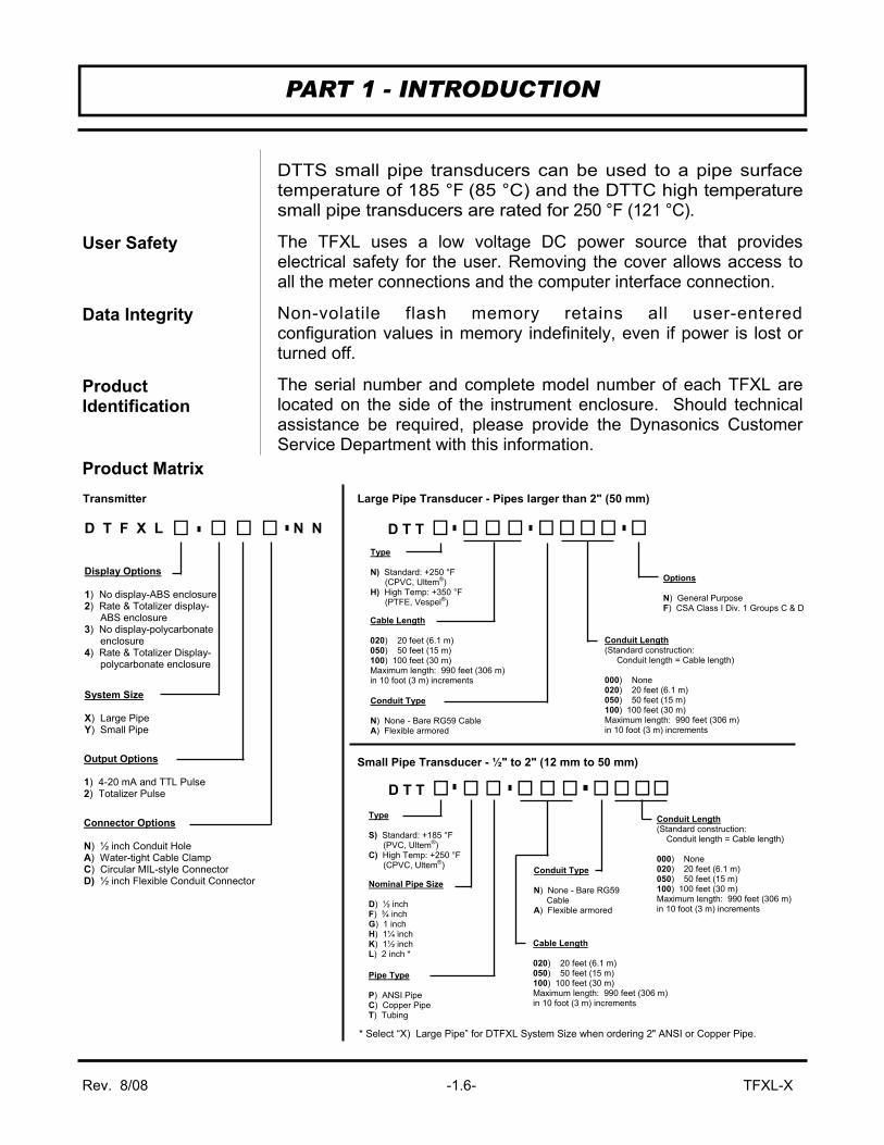
Product Matrix
Connector Options N) ½ inch Conduit Hole A) Water-tight Cable Clamp C) Circular MIL-style Connector D) ½ inch Flexible Conduit Connector
Display Options 1) No display-ABS enclosure 2) Rate & Totalizer display- ABS enclosure 3) No display-polycarbonate enclosure 4) Rate & Totalizer Display- polycarbonate enclosure
Output Options 1) 4-20 mA and TTL Pulse 2) Totalizer Pulse
D T T Type N) Standard: +250 °F (CPVC, Ultem®) H) High Temp: +350 °F (PTFE, Vespel®)
Cable Length 020) 20 feet (6.1 m) 050) 50 feet (15 m) 100) 100 feet (30 m) Maximum length: 990 feet (306 m) in 10 foot (3 m) increments
Conduit Type N) None - Bare RG59 Cable A) Flexible armored
Options N) General Purpose F) CSA Class I Div. 1 Groups C & D
Conduit Length (Standard construction: Conduit length = Cable length) 000) None 020) 20 feet (6.1 m) 050) 50 feet (15 m) 100) 100 feet (30 m) Maximum length: 990 feet (306 m) in 10 foot (3 m) increments
System Size X) Large Pipe Y) Small Pipe
D T F X L N N
Large Pipe Transducer - Pipes larger than 2" (50 mm)
Small Pipe Transducer - ½" to 2" (12 mm to 50 mm)
D T T
Pipe Type P) ANSI Pipe C) Copper Pipe T) Tubing
Conduit Length (Standard construction: Conduit length = Cable length) 000) None 020) 20 feet (6.1 m) 050) 50 feet (15 m) 100) 100 feet (30 m) Maximum length: 990 feet (306 m) in 10 foot (3 m) increments
Cable Length 020) 20 feet (6.1 m) 050) 50 feet (15 m) 100) 100 feet (30 m) Maximum length: 990 feet (306 m) in 10 foot (3 m) increments
Conduit Type N) None - Bare RG59 Cable A) Flexible armored
Nominal Pipe Size D) ½ inch F) ¾ inch G) 1 inch H) 1¼ inch K) 1½ inch L) 2 inch *
Type S) Standard: +185 °F (PVC, Ultem®) C) High Temp: +250 °F (CPVC, Ultem®)
* Select “X) Large Pipe” for DTFXL System Size when ordering 2" ANSI or Copper Pipe.
Transmitter
Rev. 8/08 -1.7- TFXL-X
PART 1 - SPECIFICATIONS
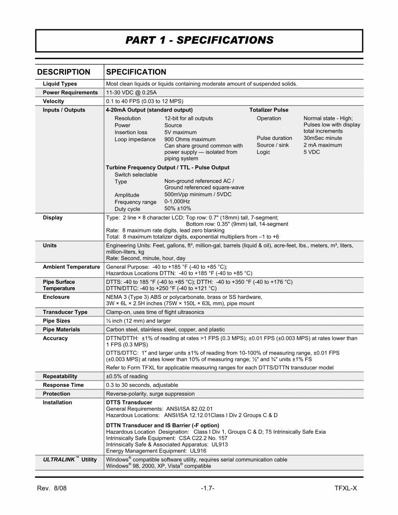
DESCRIPTION SPECIFICATION Liquid Types Most clean liquids or liquids containing moderate amount of suspended solids. Power Requirements 11-30 VDC @ 0.25A Velocity 0.1 to 40 FPS (0.03 to 12 MPS) Inputs / Outputs
Display Type: 2 line × 8 character LCD; Top row: 0.7" (18mm) tall, 7-segment; Bottom row: 0.35" (9mm) tall, 14-segment Rate: 8 maximum rate digits, lead zero blanking Total: 8 maximum totalizer digits, exponential multipliers from –1 to +6
Units Engineering Units: Feet, gallons, ft³, million-gal, barrels (liquid & oil), acre-feet, lbs., meters, m³, liters, million-liters, kg Rate: Second, minute, hour, day
Ambient Temperature General Purpose: -40 to +185 °F (-40 to +85 °C); Hazardous Locations DTTN: -40 to +185 °F (-40 to +85 °C)
Pipe Surface Temperature
DTTS: -40 to 185 °F (-40 to +85 °C); DTTH: -40 to +350 °F (-40 to +176 °C) DTTN/DTTC: -40 to +250 °F (-40 to +121 °C)
Enclosure NEMA 3 (Type 3) ABS or polycarbonate, brass or SS hardware, 3W × 6L × 2.5H inches (75W × 150L × 63L mm), pipe mount
Transducer Type Clamp-on, uses time of flight ultrasonics Pipe Sizes ½ inch (12 mm) and larger Pipe Materials Carbon steel, stainless steel, copper, and plastic Accuracy DTTN/DTTH: ±1% of reading at rates >1 FPS (0.3 MPS); ±0.01 FPS (±0.003 MPS) at rates lower than
1 FPS (0.3 MPS) DTTS/DTTC: 1" and larger units ±1% of reading from 10-100% of measuring range, ±0.01 FPS (±0.003 MPS) at rates lower than 10% of measuring range; ½" and ¾" units ±1% FS Refer to Form TFXL for applicable measuring ranges for each DTTS/DTTN transducer model
Repeatability ±0.5% of reading Response Time 0.3 to 30 seconds, adjustable Protection Reverse-polarity, surge suppression Installation DTTS Transducer
General Requirements: ANSI/ISA 82.02.01 Hazardous Locations: ANSI/ISA 12.12.01Class I Div 2 Groups C & D
DTTN Transducer and IS Barrier (-F option) Hazardous Location Designation: Class I Div 1, Groups C & D; T5 Intrinsically Safe Exia Intrinsically Safe Equipment: CSA C22.2 No. 157 Intrinsically Safe & Associated Apparatus: UL913 Energy Management Equipment: UL916
ULTRALINK ™ Utility Windows® compatible software utility, requires serial communication cable Windows® 98, 2000, XP, Vista® compatible
4-20mA Output (standard output) Resolution
Power Insertion loss Loop impedance
12-bit for all outputs Source 5V maximum 900 Ohms maximum Can share ground common with power supply — isolated from piping system
Operation Pulse duration Source / sink Logic
Normal state - High; Pulses low with display total increments 30mSec minute 2 mA maximum 5 VDC
Turbine Frequency Output / TTL - Pulse Output Switch selectable
Type Amplitude Frequency range Duty cycle
Non-ground referenced AC / Ground referenced square-wave 500mVpp minimum / 5VDC 0-1,000Hz 50% ±10%
Totalizer Pulse

Rev. 8/08 -1.8- TFXL-X
PART 1 - TERMINOLOGY
PC INTERFACE CABLE

Rev. 8/08 -1.9- TFXL-X
PART 1 - TRANSMITTER INSTALLATION
After unpacking, it is recommended to save the shipping carton and packing materials in case the instrument is stored or re-shipped. Inspect the equipment and carton for damage. If there is evidence of shipping damage, notify the carrier immediately. The enclosure should be mounted in an area that is convenient for servicing, calibration or for observation of the LCD readout. 1. Locate the transmitter within the length of transducer cable that
was supplied with the TFXL system. If this is not possible, it is recommended that the cable be exchanged for one that is of proper length. Both transducer cables must be of the same length.
NOTE: The transducer cable carries low level, high frequency signals. In general, it is not recommended to add additional cable to the cable supplied with the DTTN, DTTH, DTTS or DTTC transducers. If additional cable is required, contact the Dynasonics factory to arrange an exchange for a transducer with the appropriate length of cable. Cables to 990 feet (300 meters) are available. If additional cable and connections are added, ensure that they are RG59 75 Ohm compatible. 2. Mount the TFXL transmitter in a location that is:
♦ Where little vibration exists.
♦ Protected from falling corrosive fluids.
♦ Within ambient temperature limits -40 to 185 °F (-40 to 85 °C)
♦ Out of direct sunlight. Direct sunlight may increase temperatures within the transmitter to above the maximum limit.
3. If the transmitter will be subjected to a wet environment, it is
recommended that the cover remain closed after configuration is completed. The faceplate of the TFXL is watertight, but avoid letting water collect on it. Conduit hubs should be used where cables enter the enclosure. Holes not used for cable entry should be sealed with plugs.
NOTE: Use NEMA 4 (IP65) rated fittings/plugs to maintain the watertight integrity of the enclosure. Generally, the left conduit hole (viewed from front) is used for line power; the center conduit holes for transducer connections and the right holes are utilized for I/O wiring.
Transmitter Installation
Rev. 8/08 -1.10- TFXL-X
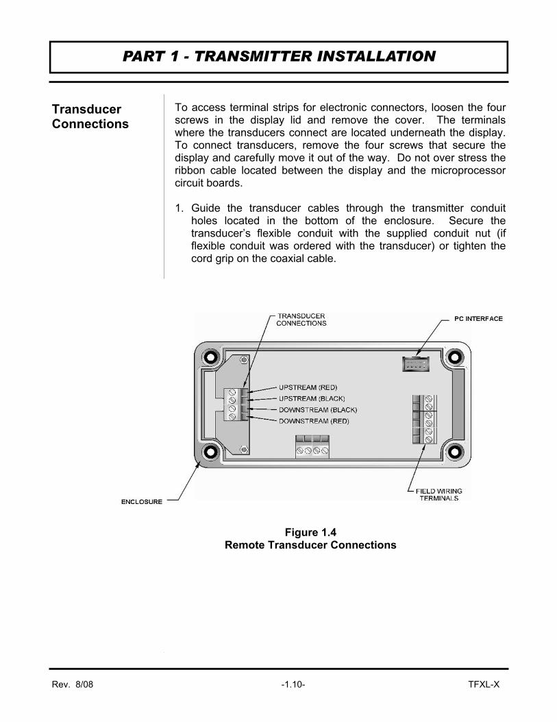
To access terminal strips for electronic connectors, loosen the four screws in the display lid and remove the cover. The terminals where the transducers connect are located underneath the display. To connect transducers, remove the four screws that secure the display and carefully move it out of the way. Do not over stress the ribbon cable located between the display and the microprocessor circuit boards. 1. Guide the transducer cables through the transmitter conduit
holes located in the bottom of the enclosure. Secure the transducer’s flexible conduit with the supplied conduit nut (if flexible conduit was ordered with the transducer) or tighten the cord grip on the coaxial cable.
PART 1 - TRANSMITTER INSTALLATION
Transducer Connections
Figure 1.4 Remote Transducer Connections
Rev. 8/08 -1.11- TFXL-X
2. The terminals within the TFXL are a cable-clamp type. Connect
the appropriate wires to the corresponding screw terminals in the transmitter. See Figure 1.4 on page 1.10. Secure wires by tightening to between 0.5 and 0.6 Nm of torque.
NOTE: The transducer cable carries low level, high frequency signals. In general, it is not recommended to add additional cable to the cable supplied with the DTTN, DTTH, DTTS or DTTC transducers. If additional cable is required, contact the Dynasonics factory to arrange an exchange for a transducer with the appropriate length of cable. Cables to 990 feet (300 meters) are available. If additional cable and connections are added, ensure that they are RG59 75 Ohm compatible. FIELD WIRING — GENERAL The remote mount TFXL is equipped with two conduit holes located in the flow meter enclosure that should be suitable for most installations. A sealed cord grip or NEMA 4 conduit connection should be utilized to retain the NEMA 3 integrity of the flow meter enclosure. Failure to do so will void the manufacturer’s warranty and can lead to product failure.
Wiring methods and practices are to be made in accordance with the NEC — National Electric Code® — and/or other local ordinances that may be in effect. Consult the local electrical inspector for information regarding wiring regulations.
When making connections to the field wiring terminals inside the flow meter, strip back the wire insulation approximately 0.25 inch (6 mm). Stripping back too little may cause the terminals to clamp on the insulation and not make good contact. Stripping back too much insulation may lead to a situation where the wires could short together between adjacent terminals. Wires should be secured in the field wiring terminals using a screw torque of between 0.5 and 0.6 Nm. G. FIELD WIRING — POWER Power for the TFXL flow meter is obtained from a direct current (DC) power source. The power source should be capable of supplying between 11 and 30 Vdc at a minimum of 0.25 Amps or 250 milliamps. With the power from the DC power source disabled
PART 1 - TRANSMITTER INSTALLATION
Transmitter Power Connections
DC Power Supply

Rev. 8/08 -1.12- TFXL-X
or disconnected, connect the positive supply wire and ground to the appropriate field wiring terminals in the flow meter. See Figure 1.5. A wiring diagram decal is located on the inner cover of the flow meter enclosure.
If the flow meter is only to be utilized as a flow rate indicator or totalizer, no further wiring will be required. Skip to Page 1.17.
PART 1 - TRANSMITTER INSTALLATION
Figure 1.5 DC Power Connection
11-30 VDC DC Ground
11 to 30 Vdc
IMPORTANT NOTE: Not following instructions properly may impair safety of equipment and/or personnel.
IMPORTANT NOTE: Must be operated by a power supply suitable for the location.
IMPORTANT NOTE: Do not connect or disconnect either power or outputs unless the area is known to be non-hazardous.
IMPORTANT NOTE: Do not connect the interface cable between a TFXL and a personal computer unless the area is known to be non-hazardous.
!
!
!
!

Rev. 8/08 -1.13- TFXL-X
CONNECTING THE 4-20 mA OUTPUT The TFXL is equipped with a ground-referenced 4-20 mA output — the output shares a common ground with the power supply. The output transmits a continuous current output that is proportional to liquid flow rate. The output was scaled at the Dynasonics factory and the scaling information is recorded on the label located on the side of the TFXL enclosure. To ensure that the instrument or data acquisition system that is receiving the 4-20 mA signal responds properly, it must be spanned identically to the TFXL. The 4-20 mA output is designed to source current across a loop resistance that is typically located within a data acquisition system or other receiving instrument. The maximum resistance that the TFXL can accommodate is directly related to the DC power source that is powering the flow meter and the 4-20 mA loop. Chart 1.1 illustrates the range of load resistance that can be used with a given power supply voltage. Ensure that the loop load resistance is within the shaded region of the graph or non-linearity and transmitting errors will occur.
The 4-20 mA output is polarized and since the output shares the DC common with the power supply, reversing the connections can cause a short circuit in the DC power circuit. Figure 1.6 on page 1.14 shows a block diagram of how the 4-20 mA interfaces with the receiving device.
PART 1 - INPUT/OUTPUT CONFIGURATION
Output Configuration
Chart 1.1 4-20 mA Loop Load
Ope rate in the
Sha ded Reg ion

Rev. 8/08 -1.14- TFXL-X
Connect the wires to the appropriate Field Wiring Terminals within the TFXL enclosure. See Figure 1.7.
PART 1 - INPUT/OUTPUT CONFIGURATION
Figure 1.6 4-20 mA Block Diagram
4-20 mA Ground
4-20 mA Output
Figure 1.7 4-20 mA Connections

Rev. 8/08 -1.15- TFXL-X
CONNECTING THE PULSE OUTPUT The TFXL is equipped with a circuit that outputs a pulse waveform that varies proportionally with flow rate. The quantity of pulses per unit volume of liquid is described by the K-factor that is recorded on the side of the flow meter enclosure. To ensure that accurate readings are being recorded by the receiving instrument, the TFXL and the receiving instrument must have identical K-factor values programmed into them. The K-factor for TFXL transmitters utilizing small pipe transducers (DTTS and DTTC) are fixed. These values are recorded on the side of the TFXL enclosure. If the TFXL is to be used on large pipes (2" and above), the K-factor must be calculated for the particular maximum flow rate pro-grammed into the meter. The K-factor is:
For example – the full scale flow for a 1" pipe is 15 GPM. The K-factor would then be: Two pulse output options are available with the TFXL: ♦ Turbine meter simulation (SW1 ON) — This option is utilized
when a receiving instrument is capable of interfacing directly with a turbine flow meter’s magnetic pickup. The output is a relatively low voltage AC signal that is not ground referenced. The minimum AC amplitude is approximately 500 mV peak-to-peak.
This option is selected by placing SW1 in the ON position. See Figure 1.8 on page 1.16.
♦ TTL pulse frequency (SW1 OFF) — This option is utilized when a receiving instrument requires that the pulse voltage level be either of a higher potential and/or referenced to DC ground. The output is a square wave with a peak-to-peak voltage swing of 5 volts.
This option is selected by placing SW1 in the OFF position. See Figure 1.8 on page 1.16.
PART 1 - INPUT/OUTPUT CONFIGURATION
60,000 = 3,000 pulses per gallon15 GPM
60,000 = K-factorFull Scale Flow

Rev. 8/08 -1.16- TFXL-X
RATE PULSE OUTPUT CONNECTIONS
Connection of rate pulse output is simply a matter of connecting the two field wiring terminals to the pulse input on the receiving instrument and verifying that the K-factor is programmed into the receiving instrument.
The simulated turbine output is not referenced to DC ground and is not polarized, so wiring polarity is not important. See Figure 1.9.
The TTL output is referenced to DC ground and is polarized. When using the TTL pulse, connect the plus (+) field terminal in the flow meter to the frequency input on the receiving instrument. Connect the negative (-) field terminal to the frequency input negative or DC common connection in the receiving instrument. See Figure 1.9.
PART 1 - INPUT/OUTPUT CONFIGURATION
Figure 1.8 Rate Pulse Output Switch Positions
Figure 1.9 Pulse Output Field Wiring Connections

Rev. 8/08 -1.17- TFXL-X
APPLYING POWER TO THE TFXL The TFXL flow meter requires a full pipe of liquid before a successful startup can be completed. Do not attempt to make adjustments or change configurations until a full pipe is verified. 1. Verify that all wiring is properly connected and routed as
described in this manual. 2. Verify that the flow sensor is properly mounted and that the
acoustic grease is intact between the transducer faces and the pipe.
3. Apply power. The displays of the TFXL2 and TFXL4 (models with a display) will display a display test where all segments will illuminate in succession and then the software version will be displayed. The meter will then enter RUN Mode. If the flow meter is a TFXL1 or TFXL3 (models without a display) verify that one of the red LEDs on the main printed circuit board is illuminated continuously and that the other one begins to blink.
4. Upon entering RUN Mode, the TFXL2 and TFXL4 will provide one of the following responses: ♦ The display may indicate ERROR 0010, which indicates low
signal strength. NOTE: ERROR 0010 alternates with the flow totalizer value. Low signal strength is caused by one of the following: ⇒ an empty pipe (gas locked) ⇒ gas content in the liquid is excessive ⇒ inadequate acoustic grease between the flow meter
transducer and the pipe ⇒ a broken connection between a transducer and the main
circuit board — check wire terminations under the display.
♦ The display may indicate a flow rate. ⇒ If 0.000 is indicated, it means that the meter is operating
properly, but that the liquid is not moving. ⇒ A negative value would indicated that flow is moving
backwards — against the flow direction arrow. A standard TFXL will not output flow signals under this condition.
PART 1 - STARTUP AND CONFIGURATION
Before Starting the Instrument
Instrument Startup
Important!

Rev. 8/08 -1.18- TFXL-X
⇒ The flow meter indicates flow rate. This verifies that
signal strength is adequate and that the flow is moving in the direction that the flow arrow signifies.
TFXL1 and TFXL3 Responses — The TFXL1 and TFXL3 are not equipped with a display, so troubleshooting requires the use of a computer and a PC interface cable. See Part 3 of this manual.
PART 1 - STARTUP AND CONFIGURATION
Rev. 8/08 - 2.1 - TFXL-X
The transducers that are utilized by the Series TFXL contain piezoelectric crystals for transmitting and receiving ultrasound signals through walls of liquid piping systems. DTTN and DTTH transducers are relatively simple and straight-forward to install, but spacing and alignment of the transducers is critical to the system's accuracy and performance. DTTS and DTTC, small-pipe transducers, have integrated transmitter and receiver elements that eliminate the requirement for spacing measurement and alignment. Extra care should be taken to ensure that these instructions are carefully executed. Mounting of the DTT clamp-on ultrasonic transit time transducers is comprised of three steps. In general, these steps consist of: 1. Selection of the optimum location on a piping system. 2. Entering the pipe and liquid parameters into the optional
software utility (ULTRALINK™). The software embedded in ULTRALINK™ and TFXL firmware will calculate proper transducer spacing based on these entries.
3. Pipe preparation and transducer mounting.
PART 2 - TRANSDUCER POSITIONING
General

Rev. 8/08 - 2.2 - TFXL-X
The first step in the installation process is the selection of an optimum location for the flow measurement to be made. For this to be done effectively, a basic knowledge of the piping system and its plumbing is required. An optimum location is defined as: • A piping system that is completely full of liquid when
measurements are being taken. The pipe may become completely empty during a process cycle — which will result in an error code being displayed on the flow meter while the pipe is empty. Error codes will clear automatically once the pipe refills with liquid. It is not recommended to mount the transducers in an area where the pipe may become partially filled. Partially filled pipes will cause erroneous and unpredictable operation of the meter.
• A piping system that contains lengths of straight pipe such as those described in Table 2.1 on page 2.3. The optimum straight pipe diameter recommendations apply to pipes in both horizontal and vertical orientation. The straight runs in Table 2.1 apply to liquid velocities that are nominally 7 FPS (2.2 MPS). As liquid velocity increases above this nominal rate, the requirement for straight pipe increases proportionally.
• Mount the transducers in an area where they will not be inadvertently bumped or disturbed during normal operation.
• Avoid installations on downward flowing pipes unless adequate downstream head pressure is present to overcome cavitation in the pipe.
PART 2 - TRANSDUCER POSITIONING
1. Mounting Location

Rev. 8/08 - 2.3 - TFXL-X
PART 2 - TRANSDUCER POSITIONING
Table 2.1 Straight Pipe Requirements

Rev. 8/08 - 2.4 - TFXL-X
TFXL transit time flow meters are sold with four different transducer types: DTTN, DTTH, DTTS and DTTC. Meters that utilize DTTN and DTTH transducers consist of two separate sensors that function as both ultrasonic transmitters and receivers. DTTS and DTTC transducers integrate both the transmitter and receiver into one assembly that fixes the separation of the piezoelectric elements. DTTN and DTTH transducers are clamped on the outside of a closed pipe at a specific distance from each other. The transducers can be mounted in V-Mount where the sound transverses the pipe two times, W-Mount where the sound transverses the pipe four times, or in Z-Mount where the transducers are mounted on opposite sides of the pipe and the sound crosses the pipe once. For further details, reference pictures located under Table 2.2 on page 2.5. The appropriate mounting configuration is based on pipe and liquid characteristics. Selection of the proper transducer mounting method is not entirely predictable and many times is an iterative process. Table 2.2 contains recommended mounting configurations for common applications. These recommended configurations may need to be modified for specific applications if such things as aeration, suspended solids or poor piping conditions are present. W-Mount provides the longest sound path length between the transducers — but the weakest signal strength. Z-Mount provides the strongest signal strength — but has the shortest sound path length. On pipes smaller than 3 inches (75 mm), it is desirable to have a longer path length so that the differential time can be measured more accurately. Use of the TFXL diagnostics in determining the optimum transducer mounting will be covered later in this section.
PART 2 - TRANSDUCER POSITIONING
2. Transducer Spacing

Rev. 8/08 - 2.5 - TFXL-X
Transducer Mounting Mode
Pipe Material Pipe Size Liquid Composition
W-Mount
Plastic (all types) Carbon Steel
Stainless Steel Copper
Ductile Iron Cast Iron
2-4 in (50-100 mm) 2-4 in (50-100 mm) 2-4 in (50-100 mm) 2-4 in (50-100 mm) Not recommended Not recommended
Low TSS; non-aerated Low TSS; non-aerated Low TSS; non-aerated Low TSS; non-aerated
V-Mount
Plastic (all types) Carbon Steel
Stainless Steel Copper
Ductile Iron Cast Iron
4-12 in (100-300 mm) 4-12 in (100-300 mm) 4-12 in (100-300 mm) 4-30 in (100-750 mm) 2-12 in (50-300 mm) 2-12 in (50-300 mm)
Low TSS; non-aerated Low TSS; non-aerated Low TSS; non-aerated Low TSS; non-aerated Low TSS; non-aerated Low TSS; non-aerated
Z-Mount
Plastic (all types) Carbon Steel
Stainless Steel Copper
Ductile Iron Cast Iron
> 30 in (> 750 mm) > 12 in (> 300 mm) > 12 in (> 300 mm) > 30 in (> 750 mm) > 12 in (> 300 mm) > 12 in (> 300 mm)
Low TSS; non-aerated Low TSS; non-aerated Low TSS; non-aerated Low TSS; non-aerated Low TSS; non-aerated Low TSS; non-aerated
W-Mount Configuration
V-Mount Configuration
Z-Mount Configuration
PART 2 - TRANSDUCER POSITIONING
Table 2.2 Transducer Mounting Modes
Transducer Mounting Modes

Rev. 8/08 - 2.6 - TFXL-X
The TFXL system calculates proper transducer spacing by utilizing piping and liquid information entered by the user. This information is entered via the ULTRALINK™ software utility. The software utility and a programming cable are required for programming TFXL instruments. NOTE: Transducer spacing is calculated on “ideal” pipe. Ideal pipe is almost never found so the transducer spacing distances should be considered as starting points. An effective way to maximize signal strength is to configure the display to show signal strength, fix one transducer on the pipe and then starting at the calculated spacing move the remaining transducer small distances forward and back to find the maximum signal strength point.
PART 2 - TRANSDUCER POSITIONING
Entering Pipe and Liquid Data
Table 2.3 Transducer Mounting Modes – DTTS / DTTC
Size Frequency Transducer Mounting Mode Size Frequency Transducer Mounting
Mode
1/2 2 MHz
DTTxnP
W 1-1/4 2 MHz
DTTxnP
W DTTxnC DTTxnC
DTTxnT DTTxnT
3/4 2 MHz
DTTxnP
W 1-1/2 2 MHz
DTTxnP
W DTTxnC DTTxnC
DTTxnT DTTxnT
1 2 MHz
DTTxnP
W 2 1 MHz
DTTxnP V
DTTxnC DTTxnC
DTTxnT 2 MHz DTTxnT W

Rev. 8/08 - 2.7 - TFXL-X
The following list of information will be required before programming the instrument. Note that much of the data relating to material sound speed, viscosity and specific gravity are preprogrammed into the TFXL flow meter. This data only needs to be modified if it is known that a particular liquid data varies from the reference value. Refer to Part 3 for data entry via ULTRALINK™ software.
1. Transducer mounting configuration - see Table 2.2 on page 2.5 2. Pipe O.D. (outside diameter) 3. Pipe wall thickness 4. Pipe material 5. Pipe sound speed1 6. Pipe relative roughness1 7. Pipe liner thickness 8. Pipe liner material 9. Pipe liner sound speed1 10. Fluid type 11. Fluid sound speed1 12. Fluid viscosity1 13. Fluid specific gravity1 1 Nominal values for these parameters are included within the TFXL operating system. The nominal values may be used as they appear or may be modified if exact system values are known. After entering the data listed above, the TFXL will calculate proper transducer spacing for the particular data set. This distance will be in inches if the TFXL is configured in English units and millimeters if configured in metric units.
Important! Enter All of the Data on this List , Save the Data and Reset the TFXL Before Mounting Transducers
PART 2 - TRANSDUCER POSITIONING
Rev. 8/08 - 2.8 - TFXL-X
After selecting an optimal mounting location (Step 1) and successfully determining the proper transducer spacing (Step 2), the transducers can now be mounted onto the pipe.
Before the transducers are mounted onto the pipe surface, two areas slightly larger than the flat surface of the transducer heads must be cleaned of all rust, scale and moisture. On rough pipe surfaces, such as ductile iron pipe, it is recommended that the pipe surface be ground flat. Paint and other coatings, if not flaked or bubbled, need not be removed. Plastic pipes typically do not require surface preparation other than soap and water cleaning.
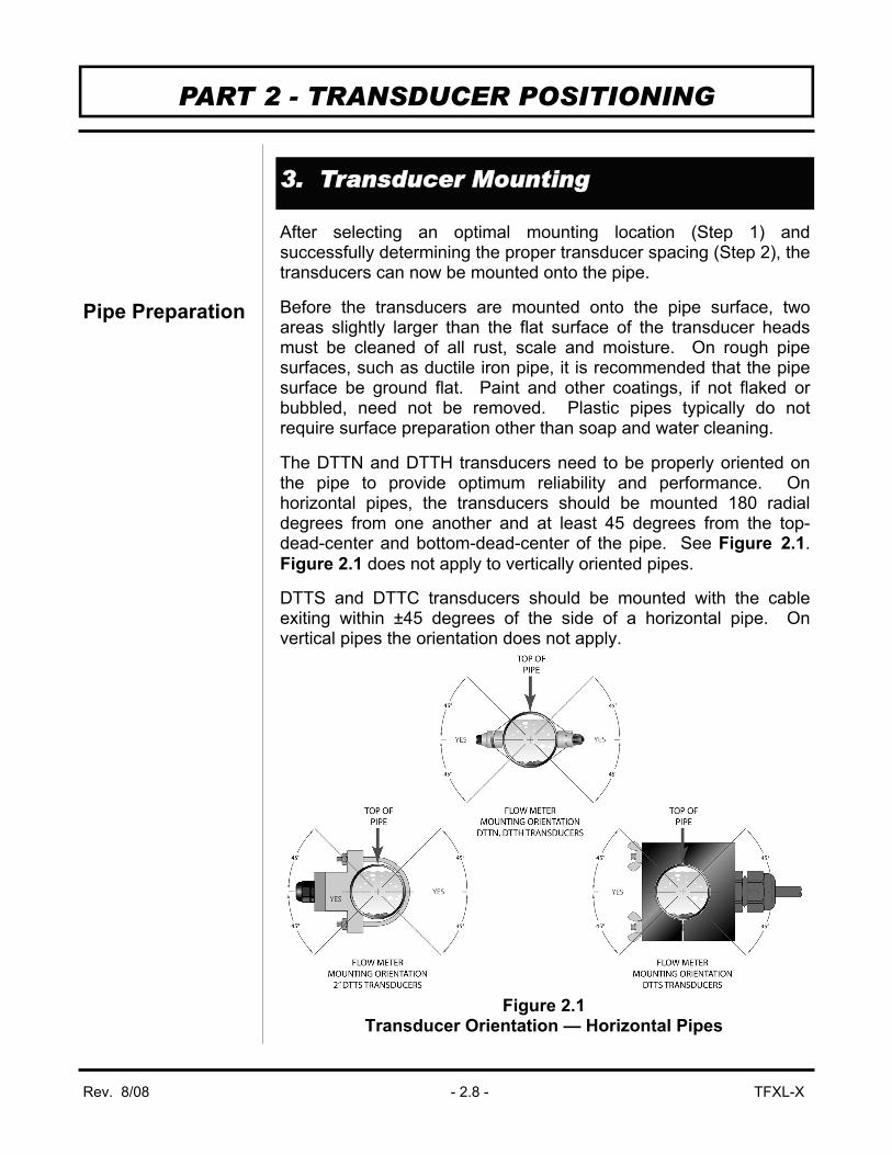
The DTTN and DTTH transducers need to be properly oriented on the pipe to provide optimum reliability and performance. On horizontal pipes, the transducers should be mounted 180 radial degrees from one another and at least 45 degrees from the top-dead-center and bottom-dead-center of the pipe. See Figure 2.1. Figure 2.1 does not apply to vertically oriented pipes.
DTTS and DTTC transducers should be mounted with the cable exiting within ±45 degrees of the side of a horizontal pipe. On vertical pipes the orientation does not apply.
PART 2 - TRANSDUCER POSITIONING
3. Transducer Mounting
Figure 2.1 Transducer Orientation — Horizontal Pipes
Pipe Preparation

Rev. 8/08 - 2.9 - TFXL-X
V-Mount and W-Mount Installation
1. For DTTN transducers, place a single bead of couplant, approximately 1/2 inch (12 mm) thick on the flat face of the transducer. See Figure 2.2. Generally, a silicone-based grease is used as an acoustic couplant, but any grease-like substance that is rated not to “flow” at the temperature that the pipe may operate at will be acceptable.
2. Place the upstream transducer in position and secure with a stainless steel strap. Straps should be placed in the arched groove on the end of the transducer. A screw is provided to help hold the transducer onto the strap. Verify that the transducer is true to the pipe — adjust as necessary. Tighten transducer strap securely.
3. Place the downstream transducer on the pipe at the calculated transducer spacing. See Figure 2.3 on page 2.10. Using firm hand pressure, slowly move the transducer both towards and away from the upstream transducer while observing Signal Strength. Clamp the transducer at the position where the highest Signal Strength is observed. Signal Strength of between 2 and 195 percent is acceptable.
4. If after adjustment of the transducers the Signal Strength does not rise to above 5 percent, then an alternate transducer mounting method should be selected. If the mounting method was W-Mount, then reconfigure the TFXL for V-Mount, reset the TFXL, move the downstream transducer to the new location and repeat Step 3.
PART 2 - TRANSDUCER POSITIONING
Figure 2.2 Application of Couplant

Rev. 8/08 - 2.10 - TFXL-X
5. Certain pipe and liquid characteristics may cause Signal Strength to rise to greater than 195 percent. The problem with operating a TFXL with very high Signal Strength is that the signals may saturate the input amplifiers and cause erratic readings. To decrease the Signal Strength, move one transducer a small distance radially around the pipe, as shown in Figure 2.4.
PART 2 - TRANSDUCER POSITIONING
Figure 2.3 Transducer Position
(Top view of pipe)
Read Signal Strength Here
Figure 2.4 High Signal Strength Condition
Read Signal Strength Here

Rev. 8/08 - 2.11 - TFXL-X
DTTH High Temperature Transducers
Mounting of high temperature transducers is similar to standard DTTN transducers except that an insulative pad is placed between the transducer and the pipe wall. High temperature installations also require acoustic couplant that is rated not to “flow” at the temperature that will be present on the pipe surface. Figure 2.5 should be referenced for insulative pad installation.
Installation of the insulative pads consists of the following steps:
1. Apply a thin coating of high temperature grease to the entire surface of the transducer face. The thickness of the application should be approximately 1/16 inch (1.5 mm).
2. Place the orange insulative pad on the prepared surface of the transducer. Press from center out to remove all air pockets.
3. Apply a 1/2 inch (12 mm) wide bead of grease to the exposed surface of the insulative pad that will contact the pipe.
4. Install the two transducers following the procedures detailed in the DTTN instructions on page 2.9 of this manual.
PART 2 - TRANSDUCER POSITIONING
DTTH Transducers for High Temperature
Figure 2.5 Insulative Pad Installation

Rev. 8/08 - 2.12 - TFXL-X
DTTS and DTTC Small Pipe Transducer Installation
The small pipe transducers offered by Dynasonics are designed for specific pipe outside diameters. Do not attempt to mount a DTTS or DTTC transducer onto a pipe that is either too large or too small for the transducer — contact the Dynasonics factory to arrange for a replacement transducer that is the correct size.
DTTS and DTTC installation consists of the following steps:
1. Apply a thin coating of silicone grease to both halves of the transducer housing where the housing will contact the pipe. See Figure 2.6.
2. On horizontal pipes, mount the transducer in an orientation such that the cable exits at ±45 degrees from the side of the pipe. Do not mount with the cable exiting on either the top or bottom of the pipe. On vertical pipes the orientation does not matter.
3. Tighten the wingnuts so that the grease begins to flow out from the edges of the transducer and from the gap between the transducer halves. Do not over tighten.
4. If Signal Strength is less than 5 percent, remount the transducer at another location on the piping system.
5. If Signal Strength is greater than 195 percent, contact Dynasonics to obtain a lower power strategy to load into the TFXL meter.
PART 2 - TRANSDUCER POSITIONING
DTTS and DTTC Small Pipe Transducer Installation
Figure 2.6 Application of Grease
DTTS Transducer
Silicone Grease

Rev. 8/08 - 2.13 - TFXL-X
Mounting Transducers in Z-Mount Configuration
Installation on larger pipes requires careful measurements to the linear and radial placement of the DTTN and DTTH transducers. Failure to properly orient and place the transducers on the pipe may lead to weak signal strength and/or inaccurate readings. The section below details a method for properly locating the transducers on larger pipes. This method requires a roll of paper such as freezer paper or wrapping paper, masking tape and a marking device.
1. Wrap the paper around the pipe in the manner shown in Figure 2.7. Align the paper ends to within 1/4 inch (6mm).
2. Mark the intersection of the two ends of the paper to indicate the circumference. Remove the template and spread it out on a flat surface. Fold the template in half, bisecting the circumference. See Figure 2.8 on page 2.14.
3. Crease the paper at the fold line. Mark the crease. Place a mark on the pipe where one of the transducers will be located. See Figure 2.1 on page 2.8 for acceptable radial orientations. Wrap the template back around the pipe, placing the beginning of the paper and one corner in the location of the mark. Move to the other side of the pipe and mark the pipe at the ends of the crease. Measure from the end of the crease (directly across the
PART 2 - TRANSDUCER POSITIONING
Z-Mount Transducer Installation
Figure 2.7 Paper Template Alignment

Rev. 8/08 - 2.14 - TFXL-X
PART 2 - TRANSDUCER POSITIONING
pipe from the first transducer location) the dimension derived in Step 2, Transducer Spacing. Mark this location on the pipe.
4. The two marks on the pipe are now properly aligned and measured.
If access to the bottom of the pipe prohibits the wrapping of the paper around the circumference, cut a piece of paper to these dimensions and lay it over the top of the pipe.
Length = Pipe O.D. × 1.57
Width = Spacing determined on page 2.6
Mark opposite corners of the paper on the pipe. Apply transducers to these two marks.
5. For DTTN transducers, place a single bead of couplant, approximately 1/2 inch (12 mm) thick, on the flat face of the transducer. See Figure 2.2 on page 2.9. Generally, a silicone-based grease is used as an acoustic couplant, but any grease-like substance that is rated to not “flow” at the temperature that the pipe may operate at, will be acceptable.
6. Place the upstream transducer in position and secure with a stainless steel strap or other. Straps should be placed in the
Figure 2.8 Bisecting the pipe circumference

Rev. 8/08 - 2.15 - TFXL-X
arched groove on the end of the transducer. A screw is provided to help hold the transducer onto the strap. Verify that the transducer is true to the pipe — adjust as necessary. Tighten transducer strap securely. Larger pipes may require more than one strap to reach the circumference of the pipe.
7. Place the downstream transducer on the pipe at the calculated transducer spacing. See Figure 2.9. Using firm hand pressure, slowly move the transducer both towards and away from the upstream transducer while observing Signal Strength. Clamp the transducer at the position where the highest Signal Strength is observed. Signal Strength of between 2 and 195 percent is acceptable. On certain pipes, a slight twist to the transducer may cause signal strength to rise to acceptable levels.
8. Certain pipe and liquid characteristics may cause Signal Strength to rise to greater than 195 percent. The problem with operating a TFXL with very high Signal Strength is that the signals may saturate the input amplifiers and cause erratic readings. To decrease the Signal Strength one transducer can be offset radially, as illustrated in Figure 2.4 on page 2.10, or a V-Mount transducer mounting method may be chosen.
9. Secure the transducer with a stainless steel strap or other.
PART 2 - TRANSDUCER POSITIONING
Figure 2.9 Z-Mount Transducer Placement
Read Signal Strength Here

Rev. 8/08 - 2.16 - TFXL-X
PART 2 - TRANSDUCER POSITIONING
D010-2102-010 Mounting Rail Installation
1. The D010-2102-010 transducer mounting track is used for pipes that have outside diameters between 2 and 10 inches (50-250 mm). If the pipe is outside of that range then select a standard V-Mount or W-Mount mounting method.
2. Install the single mounting rail on the side of the pipe with the stainless steel bands provided. Do not mount it on the top or bottom of the pipe. Orientation on vertical pipe is not critical. Ensure that the track is parallel to the pipe and that all four mounting feet are touching the pipe.
3. Slide the two transducer clamp brackets towards the center, 5 inch (125 mm) mark, on the mounting rail.
4. Place a single bead of couplant, approximately 1/2 inch (12 mm) thick, on the flat face of the transducer. See Figure 2.2 on page 2.9.
5. Place the first transducer in between the mounting rails near the zero point on the mounting rail scale. Slide the transducer clamp over the transducer. Adjust the clamp/transducer such that the notch in the clamp aligns with zero on the scale. See Figure 2.10.
Figure 2.10 D010-2102-010 Mounting Track Installation
Mounting Rail Installation

Rev. 8/08 - 2.17 - TFXL-X
6. Secure with the thumb screw. Ensure that the screw rests in the counter bore on the top of the transducer. (Excessive pressure is not required. Apply just enough pressure so that the couplant fills the gap between the pipe and transducer.)
7. Place the second transducer in between the mounting rails near the dimension derived in the Transducer Spacing section. Read the dimension on the mounting rail scale. Slide the transducer clamp over the transducer and secure with the thumb screw.
PART 2 - TRANSDUCER POSITIONING

Rev. 8/08 -3.1- TFXL-X
PART 3 - PROGRAMMING
The TFXL flow meter is available with a software utility called ULTRALINK™. The ULTRALINK™ utility is used for configuration, calibration and communication with the TFXL flow meter. ULTRALINK™ has been designed to provide a TFX user a powerful and convenient way to configure and calibrate all TFX flow meters. ULTRALINK™ can be used in conjunction with a PC communications cable — Dynasonics P.N. D010-0204-001.
System Requirements Computer type - PC, operating system Windows® 98/2000/XP/Vista®, a communications port, hard disk. Installation 1. ULTRALINK™ can be found on the Dynasonics website for no
charge or a CD can be purchased by contacting Dynasonics sales.
2. Backup/Copy all files from the website link to a folder on the computer hard disk.
3. From the "Start" command, RUN UlSetup.exe from the hard disk folder.
4. UlSetup will automatically extract and install on the hard disk and place a short-cut icon on the desktop.
5. Most PCs will require a restart after a successful installation. Initialization 1. Connect the PC to the TFX flow meter using the PC
communications cable, Dynasonics P.N. D010-0204-001. See Figure 3.1 on page 3.2.
2. Double-click on the ULTRALINK™ icon. The first screen is the “RUN-mode” screen, see Figure 3.2 on page 3.2, which contains real-time information regarding flow rate, totalizer accumulation, system signal strength, diagnostic data and the flow meter’s serial number. The indicator in the lower right-hand corner will indicate communications status. If a red ERROR is indicated, click on the Communications button on the top bar.
Important Notice!

Rev. 8/08 -3.2- TFXL-X
Click on Initialize. Choose the appropriate COM port and interface type. Proper communications are established when a green OK is indicated in the lower right-hand corner of the PC display.
PART 3 - PROGRAMMING
Figure 3.1 PC Interface Cable Connection
Figure 3.2 ULTRALINK™ Data Screen
Data Trend Minutes Data Trend Flow Rate
NOTE: Power on unit may need to be cycled in order to estab-lish communication.

Rev. 8/08 -3.3- TFXL-X
Click on the button labeled Configuration for updating flow range, liquid, pipe and I/O operating information. The first screen that appears after clicking the Configuration button is the BASIC tab.
1. BASIC TAB — See Figure 3.3 • General Units allows selection of either English (U.S.) or Metric
units of measure. If measurements of the pipe are to be entered in inches, select English. If pipe measurements are to be entered in millimeters, select Metric. It is recommended that if the General Units are altered from those at instrument startup, that the Download button be pressed on the lower right-hand portion of the screen and that the TFXL have its power cycled.
• Standard Configurations contains the most popular applications for the TFXL. TFXL flow meters with DTTN/DTTH transducers have been constructed and configured at the Dynasonics factory per the specifications provided with each customer order. If the Standard Configuration does not match the pipe schedule or material, select the proper configuration from the drop down list. If the pipe schedule is not listed or if the liquid is not water, select Other on the drop down list and fill in the proper information on the setup screen.
NOTE: TFXL flow meters with DTTS/DTTC transducers have been constructed and configured for a specific pipe size and material and should not be reconfigured.
PART 3 - PROGRAMMING
Figure 3.3 Basic Tab
Pipe and Liquid Configuration

Rev. 8/08 -3.4- TFXL-X
2. FLOW Tab — See Figure 3.4
• Flow Rate Units are selected from the pull down lists. Select an appropriate rate unit and rate time-base from the two lists.
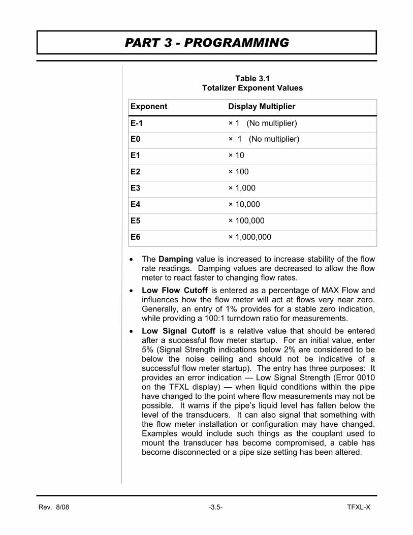
• Totalizer Units are selected from pull down lists. Select an appropriate totalizer unit and totalizer exponent. The totalizer exponents are in Scientific Notation and permit the eight digit totalizer to accumulate very large values before the totalizer “rolls over” and starts again at zero. Table 3.1 on page 3.5 illustrates the Scientific Notation values and their respective decimal equivalents.
• MIN Flow is used by the TFXL to establish filter settings in its operating system. Enter a flow rate that is the minimum flow rate anticipated within the system. For unidirectional systems, this value is typically zero. For bi-directional systems, this value is set to a negative number that is equal to the maximum negative flow rate that is anticipated within the system.
• MAX Flow is used by the TFXL to establish filter settings in its operating system. Enter a flow rate that is the maximum, positive flow rate anticipated within the system.
PART 3 - PROGRAMMING
Figure 3.4 Flow Tab
Flow Units Configuration
Rev. 8/08 -3.5- TFXL-X
• The Damping value is increased to increase stability of the flow rate readings. Damping values are decreased to allow the flow meter to react faster to changing flow rates.
• Low Flow Cutoff is entered as a percentage of MAX Flow and influences how the flow meter will act at flows very near zero. Generally, an entry of 1% provides for a stable zero indication, while providing a 100:1 turndown ratio for measurements.
• Low Signal Cutoff is a relative value that should be entered after a successful flow meter startup. For an initial value, enter 5% (Signal Strength indications below 2% are considered to be below the noise ceiling and should not be indicative of a successful flow meter startup). The entry has three purposes: It provides an error indication — Low Signal Strength (Error 0010 on the TFXL display) — when liquid conditions within the pipe have changed to the point where flow measurements may not be possible. It warns if the pipe’s liquid level has fallen below the level of the transducers. It can also signal that something with the flow meter installation or configuration may have changed. Examples would include such things as the couplant used to mount the transducer has become compromised, a cable has become disconnected or a pipe size setting has been altered.
PART 3 - PROGRAMMING
Exponent Display Multiplier
E-1 × 1 (No multiplier)
E0 × 1 (No multiplier)
E1 × 10
E2 × 100
E3 × 1,000
E4 × 10,000
E5 × 100,000
E6 × 1,000,000
Table 3.1 Totalizer Exponent Values

Rev. 8/08 -3.6- TFXL-X
• Substitute Flow is used to provide an indication and output that signifies that an error exists with the flow meter or its setup. It is set as a percentage between MIN Flow and MAX Flow. In a unidirectional system, this value is typically set to zero to indicate zero flow while in an error condition. In a bi-directional system, the percentage can be set such that zero is displayed in an error condition. To calculate where to set the Substitute Flow value in a bi-directional system perform the following operation:
NOTE: An entry of 4,000 in the Calibration 10 kHz box will cause an output of 1,000 Hz to occur at full scale flow rate. • Vol. Correction Sig. Str. Limit is a feature used to provide
volumetric compensation for gas bubbles that can be present in liquid systems. The TFXL measures the velocity of the liquid in the pipe and converts that velocity to volume by multiplying the velocity by the cross-sectional area of the pipe. If there are gas bubbles within the liquid, the gas is displacing some of the liquid and errors can occur. When Vol. Correction Sig. Str. Limit is set to zero, the compensation function is not operational. To use the feature, enter the maximum Signal Strength observed on the flow meter after installation. The maximum signal strength should occur with the pipe completely full of liquid and the flow stopped. Signal Strength can be observed on the ULTRALINK™ Data Screen. See Figure 3.2 on page 3.2.
• Entry of data in the Basic and Flow tabs are all that is required to provide flow measurement functions to the flow meter. If the user is not going to utilize input/output functions, click on the Download button to transfer the configuration to the TFXL instrument.
PART 3 - PROGRAMMING
Saving the Configuration
) Substitute Flow = 100 – 100 × MAX Flow
MAX Flow – MIN Flow (

Rev. 8/08 -3.7- TFXL-X
3. ADVANCED TAB — See Figure 3.5 The Advanced TAB contains several filter settings for the TFXL flow meter. These filters can be adjusted to match response times and data “smoothing” performance to a particular application. The factory settings are suitable for most installations.
• Time Domain Filter adjusts the number of raw data sets (the wave forms viewed on the ULTRALINK™ Diagnostics Screen) that are averaged together. Increasing this value will provide greater damping of the data and slow the response time of the flow meter. This filter is not adaptive — it is operational to the value set at all times.
• Low Signal Cutoff is a duplicate entry from page 3.5. Adjusting this value adjusts the value on the Flow TAB.
• Substitute Flow is a duplicate entry from page 3.5. Adjusting this value adjusts the value on the Flow TAB.
• Short Pulse Duration is a function used on pipes larger than 8 inches (200 mm). Set this value to zero to disable the function. This value is factory set and should not be altered.
• Flow Filter Damping establishes a maximum adaptive filter value. Under stable flow conditions (flow that varies less than
PART 3 - PROGRAMMING
Figure 3.5 Advanced Tab
Meter Filter Configuration

Rev. 8/08 -3.8- TFXL-X
the Flow Filter Hysteresis entry), this adaptive filter will increase the number of successive flow readings that are averaged together up to this maximum value. If flow changes outside of the Flow Filter Hysteresis window, the Flow Filter adapts by decreasing and allows the meter to react faster. Increasing this value tends to provide smoother steady-state flow readings and outputs.
• Flow Filter Hysteresis creates a window around the average flow measurement reading; whereby if the flow varies within that window, greater Flow Filter Damping will occur. The filter also establishes a flow rate window where measurements outside of the window are captured by the Bad Data Rejection Filter. The value is entered as a percentage of actual flow rate.
Example: If the average flow rate is 100 GPM and the Flow Filter Hysteresis is set to 5%, a filter window of 95-105 GPM is established. Successive flow measurements that are measured within that window are recorded and averaged in accordance with the Flow Filter Damping setting. Flow readings outside of the window are held up in accordance with the Bad Data Rejection Filter.
• Flow Filter MinHysteresis sets a minimum hysteresis window that is invoked at low flow rates, where the “of rate” Flow Filter Hysteresis is very small and ineffective. This entry is entered in picoseconds and is differential time. This value is factory set and should not be altered without consulting the Dynasonics technical services department.
• Flow Filter Sensitivity allows configuration of how fast the Flow Filter Damping will adapt in the positive direction. Increasing this value allows greater damping to occur faster than lower values. Adaptation in the negative direction is not user adjustable.
• Bad Data Rejection is a value related to the number of successive readings that must be measured outside of the Flow Filter Hysteresis and Flow Filter MinHysteresis windows before the flow meter will use that flow value. Larger values are entered into the Bad Data Rejection when measuring liquids that contain gas bubbles, as the gas bubbles tend to disturb the ultrasonic signals and cause more extraneous flow readings to occur. Larger Bad Data Rejection values tend to make the flow meter more sluggish to rapid changes in actual flow rate.
PART 3 - PROGRAMMING

Rev. 8/08 -3.9- TFXL-X
4. Output TAB — See Figure 3.6 The entries made in the Output TAB establish range factors for the 4-20 mA and frequency outputs on the flow meter. The current output is calibrated at the Dynasonics factory and cannot be altered in the field. The range of the output can be altered.
The label located on the outside of the TFXL enclosure contains information on how the flow meter outputs were configured at the Dynasonics factory. A value that relates flow rate to 4 mA output, flow rate to 20 mA output and K-factor (pulses/gallon) are included on the label. If these factory set values corroborate with those in the data acquisition system that the TFXL is being connected to, no further adjustments are required.
PART 3 - PROGRAMMING
Figure 3.6 Output Tab
TFXL flow meters are configured at the Dynasonics factory to output a frequency and 4-20 mA signal that are typical for the size of pipe they are being applied to. Altering the K-factor setting will cause the 20 mA setting to change and it will no longer correspond to the value on the TFXL configuration label.
Output Configuration
IMPORTANT: Configuration should only be performed on Module #1. Module #2 must be left as “None” or communications between the PC and the TFXL will be compromised.
Important!

Rev. 8/08 -3.10- TFXL-X
To adjust the range of the 4-20 mA output, simply enter the flow rate that corresponds to 4 mA output in the box titled Flow@100Hz, then enter the flow rate corresponding to 20 mA at @10kHz. Click the Download button and the new range will be established. The flow rate units must be identical to the Flow Rate Units entered in the Flow TAB. See Figure 3.4 on page 3.4.
To alter the factory set K-factor setting, two pieces of information must be known — maximum flow rate and desired K-factor. Convert the maximum flow rate to gallons/second, then multiply by the desired K-factor (pulses/gallon). This value equals the maximum frequency output from the flow meter. Multiply this value by four to calculate the value to be entered into the 10 kHz Calibration box. Press the Download button to save and establish the new K-factor. By altering the factory setting, the 20 mA setting will not be correct.
Example: Maximum Flow Rate = 400 GPM Desired K-factor = 52 pulses/gallon 6.67 Gallons/second = 400 Gallons/minute 346.67 Hz = 6.67 Gallons/second × 52 pulses/gallon 1,386.67 = 346.67 Hz × 4 Enter 1,387 into the box at Calibration 10 kHz
NOTE: An entry of 4,000 in the Calibration 10 kHz box will cause an output of 1,000 Hz to occur at full scale flow rate.
PART 3 - PROGRAMMING

Rev. 8/08 -3.11- TFXL-X
5. Display TAB — See Figure 3.7 The Display TAB permits configuration of the flow meter display.
Display • Select Flow to display flow rate only on the display. • Select Total to display the flow accumulator only on the display. • Select Both to periodically toggle between rate and
accumulated flow displays. Display Total • Select Net to display the accumulated difference between the
positive and negative totalizers. This feature will subtract backflow (drain back) from the totalizer value.
• Select Positive to display only flows moving in the forward direction.
• Select Negative to display only flows moving in the backwards direction.
Display Dwell Time Enter a value between 1 and 10 seconds to establish how long the flow meter will display flow rate, then accumulated total, then rate and so on.
PART 3 - PROGRAMMING
Figure 3.7 Display Tab
Display Configuration

Rev. 8/08 -3.12- TFXL-X
PART 3 - PROGRAMMING
Setting Zero and Calibration ULTRALINK™ contains a powerful multi-point calibration routine that can be used to calibrate the TFXL flow meter to a primary measuring standard in a particular installation. To initialize the three step calibration routine, press the Calibration button located on the top of the ULTRALINK™ Data Screen. The display shown in Figure 3.8 will appear. The first step in the calibration process is the selection of the engineering units that the calibration will be performed with. Select the units and press the Next button at the bottom of the window. NOTE: Changes here will invalidate the current calibration.
The second screen, Figure 3.9 on page 3.13, establishes a baseline zero flow rate measurement for the instrument. To zero the flow meter, establish zero flow in the pipe (turn off all pumps and close a dead-heading valve). Wait until the Delta-time interval shown in Figure 3.9 is stable (and typically very close to zero). Press the Set button. Press the Next button when complete, then press the Finish button on the Calibration Screen. If the Set button was pressed, do not proceed with Flow Rate Calibration before pressing the Finish button to save the Zero setting.
Figure 3.8 Calibration Units
Flow Meter Calibration

Rev. 8/08 -3.13- TFXL-X
PART 3 - PROGRAMMING
The screen shown in Figure 3.10 on page 3.14 allows multiple actual flow rates to be run past the meter and the values recorded by the TFXL. To calibrate a point, establish a stable, known flow rate (verified by a real-time primary flow instrument), enter the actual flow rate in the Figure 3.10 window and press the Set button. Repeat for as many points as desired. Note: If only one point is to be used, it is preferred that a flow rate as high as anticipated in normal operation is used as the calibration point. If an erroneous data point is collected, the point can be removed by pressing the Edit button, selecting the bad point and selecting Remove.
Press the Finish button when all points have been gathered.
Figure 3.9 Setting Zero Flow
Wait for Stable Reading
WARNING: Do not enter a zero point on this screen. A zero will cause the TFXL to read no flow.
!

Rev. 8/08 -3.14- TFXL-X
PART 3 - PROGRAMMING
Saving Meter Configuration on a PC The complete configuration of the flow meter can be saved from the Configuration screen. Select Save and name the file. This file may be transferred to other flow meters or may be recalled should the same pipe be surveyed again or multiple meters programmed with the same information. Printing a Flow Meter Configuration and Calibration Report Select File from the upper task bar and Print to print a calibration and configuration information sheet for the flow meter installation. Maintenance No periodic maintenance is required for this product.
Figure 3.10
Flow Rate Calibration
Enter Actual Flow Rate


A P P E N D I X


Fluid Properties
Original Date: 7/30/1999Revision: ARevision Date: 9/10/2003File: I:/dynasonics/dyna_code/tables/fluid_ss.xls
Fluid Specific Gravity Sound Speed delta-v/degree C Kinematic Viscosity Absolute Viscosity 20 degrees C m/s ft/s m/s/degree C Centistokes Centipoise
Acetate, Butyl 1270 4163.9Acetate, Ethyl 0.901 1085 3559.7 4.4 0.489 0.441Acetate, Methyl 0.934 1211 3973.1 0.407 0.380Acetate, Propyl 1280 4196.7Acetone 0.79 1174 3851.7 4.5 0.399 0.316Alcohol 0.79 1207 3960.0 4.0 1.396 1.101Alcohol, Butyl 0.83 1270 4163.9 3.3 3.239 2.688Alcohol, Ethyl 0.83 1180 3868.9 4 1.396 1.159Alcohol, Methyl 0.791 1120 3672.1 2.92 0.695 0.550Alcohol, Propyl 1170 3836.1Alcohol, Propyl 0.78 1222 4009.2 2.549 1.988Ammonia 0.77 1729 5672.6 6.7 0.292 0.225Anlline 1.02 1639 5377.3 4.0 3.630 3.710Benzene 0.88 1306 4284.8 4.7 0.711 0.625Benzol, Ethyl 0.867 1338 4389.8 0.797 0.691Bromine 2.93 889 2916.7 3.0 0.323 0.946n-Butane 0.60 1085 3559.7 5.8Butyrate, Ethyl 1170 3836.1Carbon dioxide 1.10 839 2752.6 7.7 0.137 0.151Carbon tetrachloride 1.60 926 3038.1 2.5 0.607 0.968Chloro-benezene 1.11 1273 4176.5 3.6 0.722 0.799Chloroform 1.49 979 3211.9 3.4 0.550 0.819Diethyl ether 0.71 985 3231.6 4.9 0.311 0.222Diethyl Ketone 1310 4295.1Diethylene glycol 1.12 1586 5203.4 2.4Ethanol 0.79 1207 3960.0 4.0 1.390 1.097Ethyl alcohol 0.79 1207 3960.0 4.0 1.396 1.101Ether 0.71 985 3231.6 4.9 0.311 0.222Ethyl ether 0.71 985 3231.6 4.9 0.311 0.222Ethylene glycol 1.11 1658 5439.6 2.1 17.208 19.153Freon R12 774.2 2540Gasoline 0.7 1250 4098.4Glycerin 1.26 1904 6246.7 2.2 757.100 953.946Glycol 1.11 1658 5439.6 2.1Isobutanol 0.81 1212 3976.4Iso-Butane 1219.8 4002Isopentane 0.62 980 3215.2 4.8 0.340 0.211Isopropanol 0.79 1170 3838.6 2.718 2.134Isopropyl alcohol 0.79 1170 3838.6 2.718 2.134Kerosene 0.81 1324 4343.8 3.6Linalool 1400 4590.2Linseed Oil .925-.939 1770 5803.3Methanol 0.79 1076 3530.2 2.92 0.695 0.550Methyl alcohol 0.79 1076 3530.2 2.92 0.695 0.550Methylene chloride 1.33 1070 3510.5 3.94 0.310 0.411Methylethyl Ketone 1210 3967.2Motor Oil (SAE 20/30) .88-.935 1487 4875.4Octane 0.70 1172 3845.1 4.14 0.730 0.513

Oil, Castor 0.97 1477 4845.8 3.6 0.670 0.649Oil, Diesel 0.80 1250 4101Oil (Lubricating X200) 1530 5019.9Oil (Olive) 0.91 1431 4694.9 2.75 100.000 91.200Oil (Peanut) 0.94 1458 4783.5Paraffin Oil 1420 4655.7Pentane 0.626 1020 3346.5 0.363 0.227Petroleum 0.876 1290 4229.51-Propanol 0.78 1222 4009.2Refrigerant 11 1.49 828.3 2717.5 3.56Refrigerant 12 1.52 774.1 2539.7 4.24Refrigerant 14 1.75 875.24 2871.5 6.61Refrigerant 21 1.43 891 2923.2 3.97Refrigerant 22 1.49 893.9 2932.7 4.79Refrigerant 113 1.56 783.7 2571.2 3.44Refrigerant 114 1.46 665.3 2182.7 3.73Refrigerant 115 656.4 2153.5 4.42Refrigerant C318 1.62 574 1883.2 3.88Silicone (30 cp) 0.99 990 3248 30.000 29.790Toluene 0.87 1328 4357 4.27 0.644 0.558Transformer Oil 1390 4557.4Trichlorethylene 1050 3442.61,1,1-Trichloro-ethane 1.33 985 3231.6 0.902 1.200Turpentine 0.88 1255 4117.5 1.400 1.232Water, distilled 0.996 1498 4914.7 -2.4 1.000 0.996Water, heavy 1 1400 4593Water, sea 1.025 1531 5023 -2.4 1.000 1.025Wood Alcohol 0.791 1076 3530.2 2.92 0.695 0.550m-Xylene 0.868 1343 4406.2 0.749 0.650o-Xylene 0.897 1331.5 4368.4 4.1 0.903 0.810p-Xylene 1334 4376.8 0.662

TFX Error CodesRevised 2-22-2002
Code Number Description Correction
Warnings
0001 Serial number not present Hardware serial number has become inoperative – systemperformance will not be influenced.
0010 Signal Strength is below SignalStrength Cutoff entry
Low signal strength is typically caused by one of the following:? Empty pipe? Improper programming/incorrect values? Improper transducer spacing? Non-homogeneous pipe wall
0011 Measured Speed of Sound the in theliquid is greater than 10% different thanthe value entered during meter setup
Verify that the correct liquid was selected in the BASIC menu.Verify that pipe size parameters are correct.
0020 Heat Flow Units of measure have beenselected and an RTD module has notbeen installed
Verify that RTD Module PN D020-1045-106 has been installed inone of the I/O meter slots. Verify that OUTPUT1 or OUTPUT 2 hasbeen configured for RTD measurements.
Class C Errors
1001 System tables have changed Initiate a meter RESET by cycling power or by selecting SYSTEMRESET in the SEC MENU.
1002 System configuration has changed Initiate a meter RESET by cycling power or by selecting SYSTEMRESET in the SEC MENU.
Class B Errors
3001 Invalid hardware configuration Upload corrected file
3002 Invalid system configuration Upload corrected file
3003 Invalid strategy file Upload corrected file
3004 Invalid calibration data Recalibrate the system
3005 Invalid speed of sound calibration data Upload new data
3006 Bad system tables Upload new table data
3007 Data Logger is off or not present If desired, insert data logger and configure within the DatalogOperations Menu. If logger is not present, configure I/O port for nologger.
3010 One or more channels are notresponding (Multi-channel meters only)
Display indicates which secondary units are not communicatingwith Master meter. Verify wiring, configuration and address ofsecondary instrument.
3011 All channels are not responding (Multi-channel meters only)
Verify wiring, configuration and address of secondary instruments.
Class A Errors
4001 Flash memory full Return unit to factory for evaluation

Size(Inches)
O.D.Inch
I.D.Inch Wall O.D.
InchI.D.Inch Wall O.D.
InchI.D.Inch Wall O.D.
InchI.D.Inch Wall O.D.
InchI.D.Inch Wall O.D.
InchI.D.Inch Wall O.D.
InchI.D.Inch Wall O.D.
InchI.D.Inch Wall
3 3.80 3.02 0.39 3.96 3.12 0.42 3.96 3.06 0.45 3.96 3.00 0.484 4.80 3.96 0.42 5.00 4.10 0.45 5.00 4.04 0.48 5.00 3.96 0.526 6.90 6.02 0.44 7.10 6.14 0.48 7.10 6.08 0.51 7.10 6.00 0.55 7.22 6.06 0.58 7.22 6.00 0.61 7.38 6.08 0.65 7.38 6.00 0.698 9.05 8.13 0.46 9.05 8.03 0.51 9.30 8.18 0.56 9.30 8.10 0.60 9.42 8.10 0.66 9.42 8.10 0.66 9.60 8.10 0.75 9.60 8.00 0.810 11.10 10.10 0.50 11.10 9.96 0.57 11.40 10.16 0.62 11.40 10.04 0.68 11.60 10.12 0.74 11.60 10.00 0.80 11.84 10.12 0.86 11.84 10.00 0.92
12 13.20 12.12 0.54 13.20 11.96 0.62 13.50 12.14 0.68 13.50 12.00 0.75 13.78 12.14 0.82 13.78 12.00 0.89 14.08 12.14 0.97 14.08 12.00 1.0414 15.30 14.16 0.57 15.30 13.98 0.66 15.65 14.17 0.74 15.65 14.01 0.82 15.98 14.18 0.90 15.98 14.00 0.99 16.32 14.18 1.07 16.32 14.00 1.1616 17.40 16.20 0.60 17.40 16.00 0.70 17.80 16.20 0.80 17.80 16.02 0.89 18.16 16.20 0.98 18.16 16.00 1.08 18.54 16.18 1.18 18.54 16.00 1.2718 19.50 18.22 0.64 19.50 18.00 0.75 19.92 18.18 0.87 19.92 18.00 0.96 20.34 18.20 1.07 20.34 18.00 1.17 20.78 18.22 1.28 20.78 18.00 1.3920 21.60 20.26 0.67 21.60 20.00 0.80 22.06 20.22 0.92 22.06 20.00 1.03 22.54 20.24 1.15 22.54 20.00 1.27 23.02 20.24 1.39 23.02 20.00 1.51
24 25.80 24.28 0.76 25.80 24.02 0.89 26.32 24.22 1.05 26.32 24.00 1.16 26.90 24.28 1.31 26.90 24.00 1.45 27.76 24.26 1.75 27.76 24.00 1.8830 31.74 29.98 0.88 32.00 29.94 1.03 32.40 30.00 1.20 32.74 30.00 1.37 33.10 30.00 1.55 33.46 30.00 1.7336 37.96 35.98 0.99 38.30 36.00 1.15 38.70 35.98 1.36 39.16 36.00 1.58 39.60 36.00 1.80 40.04 36.00 2.0242 44.20 42.00 1.10 44.50 41.94 1.28 45.10 42.02 1.54 45.58 42.02 1.7848 50.50 47.98 1.26 50.80 47.96 1.42 51.40 47.98 1.71 51.98 48.00 1.99
54 56.66 53.96 1.35 57.10 54.00 1.55 57.80 54.00 1.90 58.40 53.94 2.2360 62.80 60.02 1.39 63.40 60.06 1.67 64.20 60.20 2.00 64.82 60.06 2.3872 75.34 72.10 1.62 76.00 72.10 1.95 76.88 72.10 2.3984 87.54 84.10 1.72 88.54 84.10 2.22
CLASS G CLASS HCLASS A
Cast Iron PipeStandard Classes
CLASS B CLASS C CLASS D CLASS E CLASS F
March, 2000

Cement Lining Std./Double Thickness
ID Wall ID Wall ID Wall ID Wall ID Wall ID Wall ID Wall
3 3.96 3.46 0.25 3.40 0.28 3.34 0.31 3.28 0.34 3.22 0.37 3.14 0.414 4.80 4.28 0.26 4.22 0.29 4.16 0.32 4.10 0.35 4.04 0.38 3.93 0.446 6.90 6.40 0.25 6.34 0.28 6.28 0.31 6.22 0.34 6.16 0.37 6.10 0.40 6.04 0.43 .123/.2508 9.05 8.51 0.27 8.45 0.30 8.39 0.33 8.33 0.36 8.27 0.39 8.21 0.42 8.15 0.45
10 11.10 10.32 0.39 10.46 0.32 10.40 0.35 10.34 0.38 10.28 0.41 10.22 0.44 10.16 0.4712 13.20 12.58 0.31 12.52 0.34 12.46 0.37 12.40 0.40 12.34 0.43 12.28 0.46 12.22 0.49
14 15.30 14.64 0.33 14.58 0.36 14.52 0.39 14.46 0.42 14.40 0.45 14.34 0.48 14.28 0.5116 17.40 16.72 0.34 16.66 0.37 16.60 0.40 16.54 0.43 16.48 0.46 16.42 0.49 16.36 0.5218 19.50 18.80 0.35 18.74 0.38 18.68 0.41 18.62 0.44 18.56 0.47 18.50 0.50 18.44 0.53 .1875/.37520 21.60 20.88 0.36 20.82 0.39 20.76 0.42 20.70 0.45 20.64 0.48 20.58 0.51 20.52 0.5424 25.80 25.04 0.38 24.98 0.41 24.92 0.44 24.86 0.47 24.80 0.50 24.74 0.53 24.68 0.56
30 32.00 31.22 0.39 31.14 0.43 31.06 0.47 30.98 0.51 30.90 0.55 30.82 0.59 30.74 0.6336 38.30 37.44 0.43 37.34 0.48 37.06 0.62 37.14 0.58 37.40 0.45 36.94 0.68 36.84 0.7342 44.50 43.56 0.47 43.44 0.53 43.32 0.59 43.20 0.65 43.08 0.71 42.96 0.77 42.84 0.83 .250/.50048 50.80 49.78 0.51 49.64 0.58 49.50 0.65 49.36 0.72 49.22 0.79 49.08 0.86 48.94 0.9354 57.10 55.96 0.57 55.80 0.65 55.64 0.73 55.48 0.81 55.32 0.89 55.16 0.97 55.00 1.05
Outside Diameter (inches)
Standard Classes
Ductile Iron Pipe
Class 54 Class 55 Class 56Class 50 Class 51 Class 52 Class 53Pipe Size
(inches)
March, 2000
ID Wall ID Wall ID Wall ID Wall ID Wall ID Wall ID Wall ID Wall ID Wall ID Wall ID Wall ID Wall ID Wall
1 1.315 1.185 0.065 1.097 0.109 1.049 1.049 0.133 0.957 0.179 0.957 0.179 0.815 0.2501.25 1.660 1.530 0.065 1.442 0.109 1.380 1.380 0.140 1.278 0.191 1.278 0.191 1.160 0.2501.5 1.900 1.770 0.065 1.682 0.109 1.610 1.610 0.145 1.500 0.200 1.500 0.200 1.338 0.2812 2.375 2.245 0.065 2.157 0.109 2.067 2.067 0.154 1.939 0.218 1.939 0.218 1.687 0.344
2.5 2.875 2.709 0.083 2.635 0.120 2.469 2.469 0.203 2.323 0.276 2.323 0.276 2.125 0.3753 3.500 3.334 0.083 3.260 0.120 3.068 3.068 0.216 2.900 0.300 2.900 0.300 2.624 0.438
3.5 4.000 3.834 0.083 3.760 0.120 3.548 3.548 0.226 3.364 0.318 3.364 0.3184 4.500 4.334 0.083 4.260 0.120 4.026 0.237 4.026 0.237 3.826 0.337 3.826 0.337 3.624 0.438 3.624 0.438 3.438 0.5315 5.563 5.345 0.109 5.295 0.134 5.047 0.258 5.047 0.258 4.813 0.375 4.813 0.375 4.563 0.500 4.563 0.500 4.313 0.6256 6.625 6.407 0.109 6.357 0.134 6.065 0.280 6.065 0.280 5.761 0.432 5.761 0.432 5.501 0.562 5.501 0.562 5.187 0.7198 8.625 8.407 0.109 8.329 0.148 8.125 0.250 8.071 0.277 7.981 0.322 7.981 0.322 7.813 0.406 7.625 0.500 7.625 0.500 7.437 0.594 7.187 0.719 7.187 0.719 6.183 1.221
10 10.750 10.482 0.134 10.42 0.165 10.25 0.250 10.13 0.310 10.02 0.365 10.020 0.365 9.750 0.500 9.750 0.500 9.562 0.594 9.312 0.719 9.062 0.844 9.062 0.844 8.500 1.125
12 12.750 12.420 0.165 12.39 0.180 12.25 0.250 12.09 0.330 12.00 0.375 11.938 0.406 11.626 0.562 11.750 0.500 11.370 0.690 11.060 0.845 10.750 1.000 10.750 1.000 10.120 1.31514 14.000 13.50 0.250 13.37 0.315 13.25 0.375 13.25 0.375 13.124 0.438 12.814 0.593 13.000 0.500 12.500 0.750 12.310 0.845 11.810 1.095 11.810 1.095 11.180 1.41016 16.000 15.50 0.250 15.37 0.315 15.25 0.375 15.25 0.375 15.000 0.500 14.688 0.656 15.000 0.500 14.310 0.845 13.930 1.035 13.560 1.220 13.560 1.220 12.810 1.59518 18.000 17.50 0.250 17.37 0.315 17.12 0.440 17.25 0.375 16.876 0.562 16.564 0.718 17.000 0.500 16.120 0.940 15.680 1.160 15.250 1.375 15.250 1.375 14.430 1.78520 20.000 19.50 0.250 19.25 0.375 19.25 0.375 19.25 0.375 18.814 0.593 18.376 0.812 19.000 0.500 17.930 1.035 17.430 1.285 17.000 1.500 17.000 1.500 16.060 1.97024 24.000 23.50 0.250 23.25 0.375 23.25 0.375 23.25 0.375 22.626 0.687 22.126 0.937 23.000 0.500 21.560 1.220 20.930 1.535 20.930 1.535 20.930 1.535 19.310 2.345
30 30.000 29.37 0.315 29.00 0.500 29.00 0.500 29.25 0.375 29.250 0.375 29.000 0.50036 36.000 35.37 0.315 35.00 0.500 35.00 0.500 35.25 0.375 35.250 0.375 35.000 0.50042 42.000 41.25 0.375 41.250 0.375 41.000 0.50048 48.000 47.25 0.375 47.250 0.375 47.000 0.500
SCH. 140 SCH. 180NominalPipe Size
Inches
OUTSIDE DIAMETER
X STG. SCH. 80 SCH. 100 SCH. 120
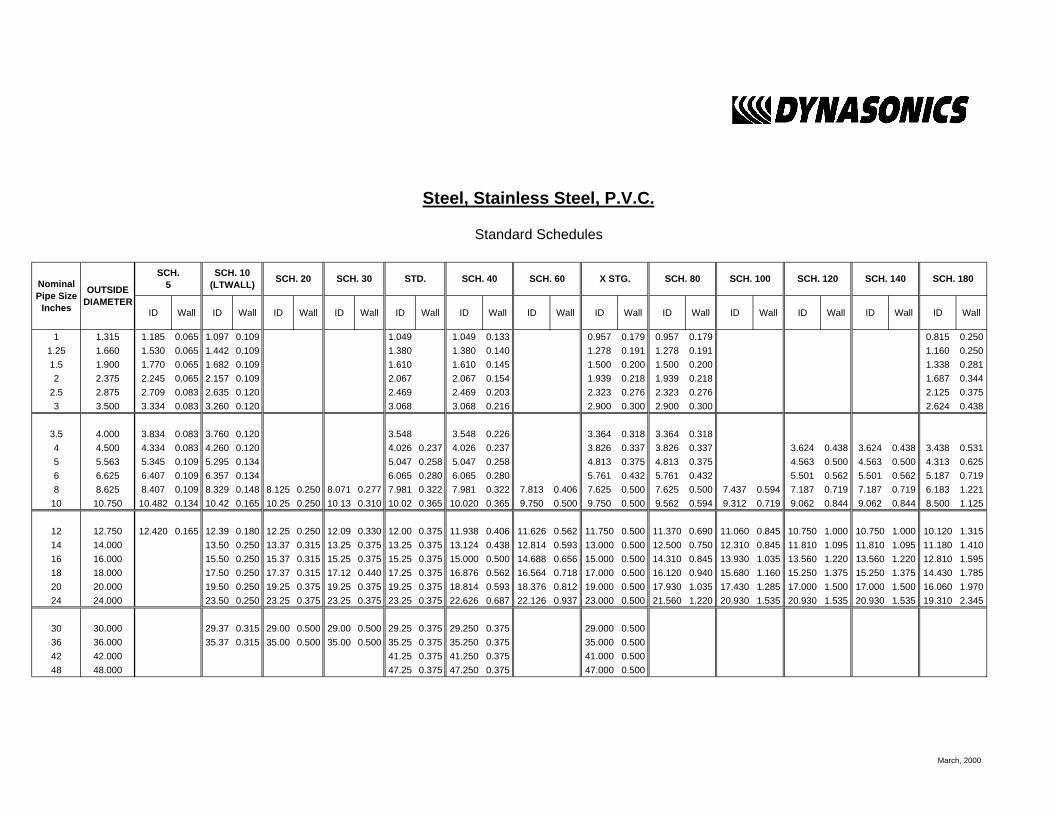
Steel, Stainless Steel, P.V.C.
Standard Schedules
SCH.5
SCH. 10 (LTWALL) SCH. 20 SCH. 30 STD. SCH. 40 SCH. 60
March, 2000

NominalPipe
(Inches)
I.D. INCH 1 1.5 2 2.5 3 3.5 4 4.5 5 5.5 6 6.5 7 7.5 8 8.5 9
1 1.05 2.6989 4.0484 5.3978 6.7473 8.097 9.4462 10.796 12.145 13.490 14.844 16.190 17.540 18.890 20.240 21.590 22.941 24.290
1.25 1.38 4.6620 6.9929 9.3239 11.655 13.99 16.317 18.648 20.979 23.310 25.641 27.970 30.300 32.630 34.960 37.300 39.627 41.958
1.5 1.61 6.3454 9.5182 12.691 15.864 19.04 22.209 25.382 28.555 31.730 34.900 38.070 41.250 44.420 47.590 50.760 53.936 57.109
2 2.07 10.489 15.734 20.979 26.224 31.47 36.713 41.958 47.202 52.450 57.692 62.940 68.180 73.430 78.670 83.920 89.160 94.405
2.5 2.47 14.935 22.402 29.870 37.337 44.80 52.272 59.740 67.207 74.670 82.142 89.610 97.080 104.50 112.00 119.50 126.95 134.41
3 3.07 23.072 34.608 46.144 57.680 69.22 80.752 92.288 103.82 115.40 126.90 138.40 150.00 161.50 173.00 184.60 196.11 207.65
3.5 3.55 30.851 46.276 61.702 77.127 92.55 107.98 123.40 138.83 154.30 169.68 185.10 200.50 216.00 231.40 246.80 262.23 277.66
4 4.03 39.758 59.636 79.515 99.394 119.3 139.15 159.03 178.91 198.80 218.67 238.50 258.40 278.30 298.20 318.10 337.94 357.82
5 5.05 62.430 93.645 124.86 156.07 187.3 218.50 249.72 280.93 312.10 343.36 374.60 405.80 437.00 468.20 499.40 530.65 561.87
6 6.06 89.899 134.85 179.80 224.75 269.7 314.65 359.60 404.55 449.50 494.45 539.40 584.30 629.30 674.20 719.20 764.14 809.09
8 7.98 155.89 233.83 311.78 389.72 467.7 545.61 623.56 701.50 779.40 857.39 935.30 1013.0 1091.0 1169.0 1247.0 1325.1 1403.0
10 10.02 245.78 368.67 491.56 614.45 737.3 860.23 983.12 1106.0 1229.0 1351.8 1475.0 1598.0 1720.0 1843.0 1966.0 2089.1 2212.0
12 11.94 348.99 523.49 697.99 872.49 1047.0 1221.5 1396.0 1570.5 1745.0 1919.5 2094.0 2268.0 2443.0 2617.0 2792.0 2966.5 3141.0
14 13.13 422.03 633.04 844.05 1055.1 1266.0 1477.1 1688.1 1899.1 2110.0 2321.1 2532.0 2743.0 2954.0 3165.0 3376.0 3587.2 3798.2
16 15.00 550.80 826.20 1101.6 1377.0 1652.0 1927.8 2203.2 2478.6 2754.0 3029.4 3305.0 3580.0 3856.0 4131.0 4406.0 4681.8 4957.2
FPS TO GPM: GPM = (PIPE ID)² X VELOCITY IN FPS X 2.45 FPS X .3048 = MPSGPM TO FPS: FPS = GPM X .0007 = GPD
GPM X 3.7878 = LPM
FPS TO GPM CROSS - REFERENCE (Schedule 40)
GPM(ID)² X 2.45

NominalPipe
(Inches)
I.D. INCH 1 1.5 2 2.5 3 3.5 4 4.5 5 5.5 6 6.5 7 7.5 8 8.5 9
FPS TO GPM CROSS - REFERENCE (Schedule 40)
18 16.88 697.52 1046.3 1395.0 1743.8 2093.0 2441.3 2790.1 3138.8 3488.0 3836.3 4185.0 4534.0 4883.0 5231.0 5580.0 5928.9 6277.7
20 18.81 866.14 1299.0 1732.0 2165.3 2598.4 3031.5 3464.6 3897.6 4330.7 4763.8 5196.8 5629.9 6063.0 6496.0 6929.1 7362.2 7795.3
24 22.63 1253.7 1880.0 2507.0 3134.1 3761.0 4387.8 5014.6 5641.5 6268.3 6895.1 7522.0 8148.8 8775.6 9402.4 10029 10656 11283
26 25.25 1560.7 2341.0 3121.0 3901.9 4682.2 5462.6 6243.0 7023.4 7803.7 8584.1 9364.5 10145 10925 11706 12486 13266 14047
28 27.25 1817.8 2727.0 3636.0 4544.5 5453.4 6362.3 7271.2 8180.0 9088.9 9997.8 10907 11816 12725 13633 14542 15451 16360
30 29.25 2094.4 3142.0 4189.0 5236.0 6283.2 7330.4 8377.6 9424.9 10472 11519 12566 13614 14661 15708 16755 17803 18850
32 31.25 2390.6 3586.0 4781.0 5976.5 7171.9 8367.2 9562.5 10758 11953 13148 14344 15539 16734 17930 19125 20320 21516
34 33.25 2706.4 4060.0 5413.0 6766.0 8119.2 9472.4 10826 12179 13532 14885 16238 17592 18945 20298 21651 23004 24358
36 35.25 3041.8 4563.0 6084.0 7604.5 9125.4 10646 12167 13688 15209 16730 18251 19772 21292 22813 24334 25855 27376
42 41.25 4165.4 6248.0 8331.0 10414 12496 14579 16662 18744 20827 22910 24992 27075 29158 31241 33323 35406 37489
48 47.99 5637.8 8457.0 11276 14095 16913 19732 22551 25370 28189 31008 33827 36646 39465 42284 45103 47922 50740
54 53.98 7133.1 10700 14266 17833 21399 24966 28532 32099 35665 39232 42798 46365 49931 53498 57065 60631 64198
60 60.09 8839.2 13259 17678 22098 26518 30937 35357 39777 44196 48616 53035 57455 61875 66294 70714 75134 79553
72 72.10 12726 19089 25451 31814 38177 44540 50903 57266 63628 69991 76354 82717 89080 95443 101805 108168 114531
84 84.10 17314 25971 34628 43285 51943 60600 69257 77914 86571 95228 103885 112542 121199 129856 138514 147171 155828
FPS TO GPM: GPM = (PIPE ID)² X VELOCITY IN FPS X 2.45 FPS X .3048 = MPSGPM TO FPS: FPS = GPM X .0007 = GPD
GPM X 3.7878 = LPM(ID)² X 2.45GPM

Limited Warranty and Disclaimer
Dynasonics, division of Racine Federated Inc. warrants to the end purchaser, for a period of one year from the date of shipment from the factory, that all new transmitters and transducers manufactured by it are free from defects in materials and workmanship. This warranty does not cover products that have been damaged due to misapplication, abuse, lack of maintenance, or improper installation. Dynasonics’ obligation under this warranty is limited to the repair or replacement of a defective product, at no charge to the end purchaser, if the product is inspected by Dynasonics and found to be defective. Repair or replacement is at Dynasonics’ discretion. A return goods authorization (RGA) number must be obtained from Dynasonics before any product may be returned for warranty repair or replacement. The product must be thoroughly cleaned and any process chemicals removed before it will be accepted for return. The purchaser must determine the applicability of the product for its desired use and assumes all risks in connection therewith. Dynasonics assumes no responsibility or liability for any omissions or errors in connection with the use of its products. Dynasonics will under no circumstances be liable for any incidental, consequential, contingent or special damages or loss to any person or property arising out of the failure of any product, component or accessory. All expressed or implied warranties, including the implied warranty of merchantability and the implied warranty of fitness for a particular purpose or application are expressly disclaimed and shall not apply to any products sold or services rendered by Dynasonics. The above warranty supersedes and is in lieu of all other warranties, either expressed or implied and all other obligations or liabilities. No agent or representative has any authority to alter the terms of this warranty in any way.

GENERAL TERMS AND CONDITIONS OF SALES 1. PAYMENT – Terms of payment are effective from the actual date of invoice. If, in the Seller’s
opinion, the financial condition of the Buyer at any time – or any other circumstances – do not justify the incurrence of production costs of shipment on the terms of payment specified, the Seller may require partial or full payment in advance. Payment terms are net 30 days unless otherwise stated on invoice.
2. F.O.B. – All shipments are from Racine, Wisconsin, USA, unless otherwise other stated, and title
transfers to the buyer upon leaving factory. 3. QUOTATION AND PRICES – Quoted prices are firm for 30 days unless stated in the quotation and
are subject to change without notice after expiration of this period. 4. TAXES – Any applicable sales, use, revenue, excise or other taxes not specifically stated in the
quotation are to be remitted by the Buyer directly to the appropriate regulatory agency. 5. WARRANTY – Seller’s standard published warranty in effect at the time of shipment shall apply.
This warranty is exclusive and is in lieu of all other warranties, express, implied, or statutory, including the warranty of merchantability.
6. DELIVERY – The Seller shall not be liable for loss or damage of any kind resulting from delay or
inability to deliver on account of flood, fire, labor trouble, riots, civil disturbances, accidents, acts or orders or regulations of civil or military authorities, shortages of material, or any other causes beyond Seller’s control.
7. PRODUCT CHANGES – In keeping with our continuing policy of product improvement, we reserve
the right to make changes in our products at any time, without incurring an obligation to change, replace or upgrade equipment previously shipped.
8. CANCELLATIONS – An order placed by Buyer and accepted by Seller may be cancelled only with
the Seller’s consent and upon terms that will indemnify the Seller against loss. 9. RESTOCKING CHARGE – On standard equipment, the charge is 25%, provided the equipment is
returned within 30 days in acceptable condition with a RGA number. Restocking charges for special equipment may vary from standard equipment, and will be handled on a case-by-case basis. No returns will be taken after one year.

RETURN OF EQUIPMENT/SALES INFORMATION
CONTACTS AND PROCEDURES
Customer Service/Application Engineer: If you have a question regarding order status, placing an order, reviewing applications for future purchases, or wish to purchase a new flow meter, please contact our new National Sales and Marketing Headquarters:
DYNASONICS Division of Racine Federated Inc.
8635 Washington Avenue Racine, WI 53406
PHONE: (800) 535-3569 or (262) 639-6770 FAX: (262) 639-2267
Service/Repair Department: If you already purchased equipment and have an operation problem, require service, or need to schedule field service, please contact our Service Department:
DYNASONICS Division of Racine Federated Inc.
8635 Washington Avenue Racine, WI 53406
PHONE: (800) 535-3569 or (262) 639-6770 FAX: (262) 639-2267
Return Goods Authorization: When returning equipment, it is necessary for you to contact our Service Department at (800) 535-3569 or (262) 639-6770 to obtain an RGA number for the authority and proper tracking of your material and its prompt inspection and return. The RGA number should be noted on the outside of the box. All returns of equipment go to the following address:
DYNASONICS Division of Racine Federated Inc.
8635 Washington Avenue Racine, WI 53406
Attn: RGA #

© 2008 Racine Federated Inc. All rights reserved.
Printed in USA TFXL-X O&M REV 8/08
8635 WASHINGTON AVENUE RACINE, WI 53406
TOLL-FREE IN NORTH AMERICA.: TEL: (800) 535-3569 FAX: (800) 732-8354 TEL: (262) 639-6770 FAX: (262) 639-2267
URL: www.dynasonics.com
DYNASONICS is a registered trademark of Racine Federated Inc. ULTRALINK is a trademark of Racine Federated Inc. Ultem is a registered trademark of General Electric Co. Vespel is a registered trademark of E.I. DuPont de Nemours and Company. National Electric Code is a registered trademark of NFPA. Windows and Vista are registered trademarks of Microsoft Corp. UL is a registered trademark of Underwriters Laboratories.