Embed Size (px)
Citation preview

for
TF Method: An Initial FrameworkModelling and Analysing Planning DomainsAustin Tater, Stephen T. Polyak:~ Peter Jarvis~
t Artificial Intelligence Applications Institute (AIAI)Department of Artificial Intelligence
The University of Edinburgh80 South Bridge, Edinburgh EH1 1HN United Kingdom
[email protected], [email protected], [email protected]
Abstract
Early work on the NONLIN and O-Plan projects in-dicated a need for a defined methodology which wouldguide users performing various roles in the acquisi-tion and analysis of domain requirements for planning.This work included links to a requirement analysismethodology, CORE (COntrolled Requirements Ex-pression), tool support via an intelligent assistant aspart of the Task Formalism (TF) Workstation and initial collection of guidelines and checklists to aid inusing the TF domain description language. This pa-per describes work underway to follow-on from thispast research and to infuse it with knowledge gainedfrom recent research related to planning domain de-velopment, knowledge modelling, design rationale andontological and requirements engineering.
Introduction
The activities involved in discovering, engineering,documenting, and maintaining a set of domain con-structs for most AI planning-based projects can be con-sidered ad hoc and disorganised, at best. The currentsources for advice on the process of writing AI planningdomain descriptions have been summarised as
"... it is the most neglected aspect of plan-ning, and there is not an established software-engineering methodology to guide this job". (Erol1995)
Domain capture and modelling has been an issuein Edinburgh-based planning research as early as thework on the NONLIN (Tate 1977) planner. In fact, theoriginal O-Plan overall architecture and system design,which dates from 1983, outlined a need for a definedmethodology which would guide users performing vari-ous roles in the acquisition and analysis of domain re-quirements for planning (Currie & Tate 1991). Thisplanning life-cycle methodology was envisioned as en-compassing a set of standardised activities and meth-ods which had well-defined design criteria, techniques,
and tools. This was proposed to assist in transform-ing planning domain development from a craft towardsmore of an engineering activity.
The domain description language used by both theNONLIN and O-Plan planners is the Task Formal-ism (TF) (Tate 1977; Tate, Drabble, & Dalton 1994a).Early prototyping efforts on a PERQ-based TF Work-station (Tate & Currie 1984; 1985) demonstrated tool-support for the domain modellers (an expert providingthe structure of the domain and specialists providingthe details) and planners (acting in any one of a rangeof roles). This tool was designed to include an "intelli-gent assistant" which would interact with the user via astructured dialogue which was tied to a specific domaindevelopment methodology. Research was conductedinto a requirements engineering methodology whichcould be adapted for use in this way. The ControlledRequirements Expression (CORE) (Mullery 1979; Cur-wen 1991) was proposed for structuring these domainmanagement activities. It is hoped that an adaptationof this method, combined with experience in workingwith TF, would help to drive the development of plan-ning domains in a more reliable fashion.
In this paper, we review past research efforts relatedto a move towards an overall TF Method framework.This includes a sampling of the guidelines and checklistincluded in the TF manual, advice on the use of TFcondition types, work on prototype tool-support viathe TF workstation and past research on links to theCORE methodology. These ideas form a base found-ation upon which new efforts from the AI planningrelated domain modelling research community may beadded.
In section 2, we present these components of theinitial TF Method. Section 3 mainly reports on exper-ience gained using this work in the development of do-main models for the construction industry. A samplingof some of the existing research on domain developmenttools and approaches from the AI planning communityis provided in section 4. Finally, in section 5, we widen
From: AAAI Technical Report WS-98-03. Compilation copyright © 1998, AAAI (www.aaai.org). All rights reserved.

the scope and discuss possible links to research in re-lated fields.
Towards a TF MethodGuidelines for Writing TF
InitiM work on pulling together the experience gainedin coding specific domains in the Task Formalism do-main description language resulted in a section on"guidelines for writing TF" which is part of the TFmanual (Tare, Drabble, & Dalton 1994a). This sectionprovides advice on the use of various TF forms andelements, which can be seen as a start towards a gen-eral framework for the development of a methodologywhich would structure the domain design activities.
This advice is rooted in a project managementperspective which describes the need for preparatorysteps and uses role identification prior to engaging inthe development-oriented activities. The central con-trolling role was identified as the Domain Expertwho is in charge of managing the scope of the do-main and introducing a "top level" description (e.g.in a house building domain this person might be anarchitect with overall responsibilities for a project).For large domain engineering efforts, a partitioningof the domain development responsibilities was recom-mended. These modular sections of the domain wereviewed as "detailed" aspects of the top level descrip-tions which were provided by the domain expert. Do-main Specialists would then be assigned to partic-ular domain partitions and would have responsibilityfor providing specifications of activities, objects (re-sources), events and effects which were relevant to theirparticular needs. The specialists may be subject mat-ter experts (e.g. in a house building domain they mightrepresent a plumber, or electrician, etc.). More likely,the domain expert and specialists may be knowledgeengineers who have performed the required knowledgeelicitation and acquisition activities from those withknowledge of the domain.
The guidelines point toward necessary project man-agement decisions such as the choice between one oftwo "main approaches" toward modelling a domain:hierarchical action expansion or goal achievement (con-ditions on world states). While these approaches canbe mixed in the specification of the domain, experi-ence had shown that it is useful, if not important, tospecify what the main approach will be for a particu-lar domain development process and to treat the otherapproach as secondary to it.
Another important management decision considersthe selection of a method for structuring the domainspecifications. A level-oriented approach to domainmodelling is proposed in this work whereby actions,
events, effects, and resources are all separated intoa series of defined and increasingly detailed levels.This helps to avoid the commonly experienced problemof "hierarchical promiscuity" (Wilkins 1988) or "levelpromiscuity" which is characterised by the inconsistentusage of various domain elements at varying areas inthe overall domain description.
This level-oriented approach is further detailed viaa checklist of activities which may suit either the ac-tion expansion approach or the goal achievement ap-proach, depending on the ordering of the defined activ-ities. This checklist includes the following activities:
¯ Identify the main actions (and events) that will ap-pear at the top of a task or plan.
¯ Develop the detailed actions (and events) for loweraction levels.
¯ Think about what world statements will be needed(effects) at which levels.
¯ Consider the conditions for actions. Ensure they areintroduced at a level which is at or below the levelat which the related effects are introduced.
¯ Add type information to restrict usage of conditions.Types are primarily used to differentiate what a con-dition means. This will lead to differences in whichcondition satisfaction methods apply. Consult thedefinitions of TF condition types (see section 2.2).
¯ Add resources at each level.
¯ Consider time restrictions and related information.
There are also notes on specific aspects/techniques
¯ Functional expression of properties
¯ Conditional actions
¯ Conditional effects
¯ Variable typing
¯ Modelling reusable, non-sharable resources (usingconditions and effects)
TF Condition Types
The guidelines on the use of condition types describedin the TF manual were detailed in (Tare, Drabble, Dalton 1994b). While the advice found in this work isoriented more towards the search effects in the plan-ning system, it has also provided a useful perspectivefor domain modellers working with levels to constrainthe use of condition types. Experience has shown thatcondition types, such as Supervised, Unsupervised,
74

and Only_use_if map to domain expertise. A verifica-tion step, which would take the specific condition typesinto account, would help to ensure that the modellinglevels are valid and that the modeller was not misusingconditions or unsuitable effects by specifying them atthe wrong level. This would assist the domain modellerwith a careful consideration of the reasons why effectswere introduced and conditions placed at a particularlevel. A consistent, verified model, extracted from thisstep, would address a major part of the "hierarchicalpromiscuity" problem.
CORE (COntrolled RequirementsExpression)
COntrolled Requirements Expression (CORE) was method developed by British Aerospace (Warton) andsystems designers in the late 70’s (Mullery 1979). Overtime, the method has evolved and CORE now providestechniques for requirements capture, analysis and spe-cification (Curwen 1991). The method can be used partition problems into manageable modules which canbe assessed using CORE analytical techniques. Thisensures that the requirements for a specification arecomplete and consistent. Some of the strengths of thismethodology include decomposability of requirementsand traceability mechanisms between different levels ofrequirements.
The CORE specifications are expressed in terms ofgraphics, structured text and mathematically basednotations. These resultant requirements models startfrom operational requirements which influence func-tional requirements and, in turn, impact implement-ation requirements (with non-functional requirementsacting as functional and implementation constraints).Viewpoints are used as logical partitionings of thesystem under consideration. These are divided intobounding viewpoints, which can be viewed from aplanning context as providers of unsupervised condi-tions and defining viewpoints which are analogousto activities which can achieve supervised conditions.Viewpoint decompositions correspond to node expan-sions. The CORE notion of "scope" addresses choicesbetween elements which may be included in the do-main, and breaks them down into "local scopes" whichdesignate responsibilities for domain specialists.
It is envisaged that an adaptation of the COREmethods can be used to structure the activities of usersacting in particular roles throughout the life-cycle ofa domain. For example, a domain expert divides adomain into a series of tasks to be completed by spe-cialists. A domain specialist can list the assumptionshe/she will be making (e.g. walls have been builtand foundation laid). Specialists can retrieve previous
plans to modify. For each plan, a viewpoint decom-position process is applied to it. This includes somechecking based on CORE analysis techniques:
¯ Does every node have at least one precursor?
¯ For every node which has a precondition, is the pre-condition satisfied by the current network or by an-other node at the same level or higher?
¯ Do precursor and successor assignments match?
CORE provides specialised techniques for inspectingthe evolving specification/domain. One example is the"viewpoint to viewpoint role-playing" technique. Us-ing this approach, a structured document is producedwhich defines a particular perspective within the do-main (e.g. between a builder and a floor installationprocedure, or between a carpet layer and a floor in-stallation procedure, etc.) Techniques such as this oneaid in combining the viewpoints by showing where con-flicting requirements are present. CORE has been usedpreviously as the controlling methodology for an ex-pert system-based requirements analysis tool (Steph-ens & Whitehead 1984)1. This tool utilised knowledgeof CORE via stored relations, entities, rules, and couldanswer questions related to a requirement specificationsuch as: how, why, and why not.
Future work will seek to adapt the CORE method-ology and to provide tool-based support for it in thestructuring of planning domain development activities.
TF Workstation
The original O-Plan design described the developmentof an intelligent, graphical user interface between anAI planning system and its users. This tool was calledthe TF workstation (Tate & Currie 1984)2. The usersof the TF workstation were separated into: those whodescribe the application domain; and those who requireplans to operate within the domain.
During domain building, the workstation assisted inbuilding up the details of the alternative actions pos-sible in the domain, the resource or time constraintson the actions, and the ways in which actions can becombined, etc. In this role, it could communicate witha domain expert and possibly several domain special-ists to elicit their knowledge about the applicationsdomain.
The TF workstation also acted as the interfacebetween a human planner and the AI planner. In
1Joint work with the O-Plan team in the mid 1980sexplored the use of O-Plan as a planning assistant withinthe Analyst Workbench
2An example screen shot from the TF workstation isshown in appendix A
75

this role, which can be thought of as a coordinationactivity, the workstation sought details of the task forwhich a plan is required. It checked that sufficient do-main knowledge was available to enable a solution tobe found (if necessary, the system pointed omissionsout to the human planner, domain expert, or domainspecialist) and acted as an intermediary to enable thehuman and AI planners to jointly generate a valid plan.
A hook for an expert system-style agent inter-face was provided to perform various services suchas searching for close matches for terminological dif-ferences or incomplete information, etc. Preliminarywork on the use of the CORE methodology withinthe TF workstation was performed (Wilson 1984).Unfortunately, this research was set aside once theinitial prototype was completed. Research is cur-rently underway to extend the original TF worksta-tion/methodology ideas as part of the Common Pro-cess Editor (CPE) which is a component in a frame-work for applying AI planning to manufacturing, mil-itary and business process management3.
TF Compiler
The O-Plan TF compiler converts the Task Formalismlanguage (coming from a file or from a domain editingtool) into the internal domain information used by theO-Plan planner. The compiler can be run increment-ally and will add to or modify the existing domaininformation available to the planner. It is anticipatedthat facilities to change specific aspects of forms previ-ously submitted will be provided, along with the cur-rent facility of simply replacing old forms or addingnew ones. There is an interaction between the facilit-ies provided by the compiler and the possible activitiesperformed in a domain life-cycle methodology. F~turework on a richer interface to the TF compiler will fa-cilitate steps in domain knowledge management whichmay overlap with planning, replanning, execution, etc.
TF Method ExperienceDomain Description Development for theConstruction Industry
The initial TF Method components were used during aresearch project at The University of Brighton to guidethe development of a TF encoding of planning know-ledge elicited from the construction industry (Jarvis& Winstanley 1998; Jarvis 1997; Jarvis & Winstan-ley 1996a; 1996b). This section outlines this work torelate industrial experiences of the TF Method fromindividuals who were at the time independent of theO-Plan design team.
3An example screen shot from the Common Process Ed-itor (CPE) is shown in appendix
Planning the Development of a DomainDescription
The first stage of the TF Method calls for a plannedapproach to the development of a domain description.It advises the identification of an overall domain ex-pert to scope and structure the domain and a numberof domain specialists to "fill-in" the structure with de-tailed knowledge. This approach worked well in theconstruction industry. The senior director used in therole of domain expert provided an overview of the plan-ning process. Managers further down the organisationused in the role of domain specialist provided detailedknowledge about the areas in which they work andtheir interactions with other specialists.
The different views of the domain expert and do-main specialists complemented one another. The ex-pert understood the overall process and the relation-ships between each stage but not the detail of how eachstage was performed. The specialists understood thedetail of their area but not the complete context inwhich they worked. Reconciling these two views ad-ded a beneficial cross check to the modelling process.Mismatches were traced to one of two causes. Eitherthe knowledge engineer had misunderstood a special-ist’s or expert’s comments or an organisational prob-lem had been encountered. In the former case, themismatch provided a useful tool for prompting bothspecialist and expert to clarify their comments. In thelatter case, the mismatch motivated the specialist andthe expert to meet and clarify their perceptions of theactual planning process they engaged in.
Selecting between Action Expansion andGoal Achievement
The second stage of the TF Method recommends aconscious commitment to either action expansion orgoal achievement as the primary modelling approachto a domain. Experimental modelling with both ap-proaches was used to inform this decision. This ex-perimentation categorised planning knowledge in theconstruction industry as being structured around thecomponents of a building and the trades or special-ists used to construct related groups of these com-ponents. A plumber, for example, is responsible forthe installation of a building’s bathroom fittings anda scaffolder is responsible for erecting the scaffoldingthat supports bricklayers in the task of constructingwalls. This structure was readily mapped to the hier-archy of schemata inherent in the action expansion ap-proach. Considering the earlier example, the overalltask of installing a building’s services was encapsulatedwithin a single schema. This schema then refined totwo schemas at a lower modelling level with the first
76

Project BuildingIComponents
AggregatelPlantEqulpment I Services FoundationsI Walls
Roof 1
Components ...........................~ .................................................................? ....................................................................~ ..................................................................~ .....................................................................~ ......................................
] I I I I I IlA,rCond,Uon,ngl(Wateraeat~ngDrainage (( w=e o00,..oo, ,oo o ll.oo, O.c ,n0 II oo,Cov...0 IPrimitiveComponents
Figure 1: Construction Domain Model Partitioned into Modelling Levels
describing the work of the plumbing specialist and thesecond the electrician specialist.
This experience with the Task Formalism providesevidence to support Drummond’s thesis (Drummond1994) that industrial planning problems are more read-ily addressed by action expansion than by goal achieve-ment techniques.
Developing the TF Schemata
The third stage of the TF Method suggests that eachschema expansion level should hold some meaningwithin the domain under consideration. Figure 1 showsa section of the building subcomponent hierarchy de-veloped from the meetings with domain experts. In thefigure, a building is shown as being decomposed into anumber of subcomponents (Plant Equipment throughto a Roof). These components are decomposed fur-ther until the level of detail required for producing aconstruction plan is reached. This structure allows ex-perts to reason at different levels of abstraction. Theassignment of the construction of the roof componentto a contractor would, for example, assume that thecontractor would then be responsible for the construc-tion of all the roof’s subcomponents (Roof Steelwork,Roof Decking and Roof Covering).
Part of the TF encoding of the components in figure1 is shown in figure 2. Figure 1 is partitioned throughthe dashed horizontal lines into the modelling levels:project components, aggregate components, and prim-itive components. These modelling levels were used toguide the encoding process. Considering the schematain figure 2, the building component at the project mod-elling level in figure 1 is encoded as the initial taskplan_buildings_construction. The transition from theproject modelling level to the aggregate modelling levelvia the subcomponent relationship is achieved in theTF encoding through the schema refinement mechan-ism. The schema build_building refines the initial task(plan_buildings_construction) and it introduces a node
for each subcomponent of the building that resideswithin the aggregate modelling level. The transitionfrom the aggregate modelling level to the primitivemodelling level is also achieved through schema re-finement as demonstrated by the schema erect_roof.The schema, which will be used to refine node 2 inthe build_building schema, contains an action for eachsubcomponent of the Roof component.
The encoding shown in figure 2 preserves both thesubcomponent structure and the modelling levels eli-cited from the domain. Figure 3 shows part of thesubcomponent structure from figure 1 augmented withthe scope of the schemata that describe that struc-ture in the TF encoding. The dashed lines representmodelling levels and the dotted lines the scope of eachschema.
task plan_buildings_construction; ;; modelling level project componetanodes 1 task {build ?building);
end_task;
schema build_building; ;; modelling level aggregate componentsexpands {build ?building}nodes I action {lay ?foundations},
2 action {erect ?roo~,3..,
end_schema;
schema erect_roof; ;; modelling level primitive componentsexpands {erect ?roof};nodes 1 action {install ?roof_steelwork),
2 action {lay ?roof.decking},3 action {lay ?roof. covedng};
end_schema;
Figure 2: Schemas build_building and erect_roof
As advised by the TF Method, the effects producedby actions were considered before the conditions re-quired by actions. Each component was consideredto determine the effect(s) that would result from itsconstruction. The components at the higher model-ling levels produce effects that describe the overall res-ult of constructing their subcomponents. Construct-ing The Foundations component, for example, addsthe effect {State_Of Foundations} = laid. The com-ponents at the lower modelling levels produce effectsthat describe their own construction. Constructing the
77
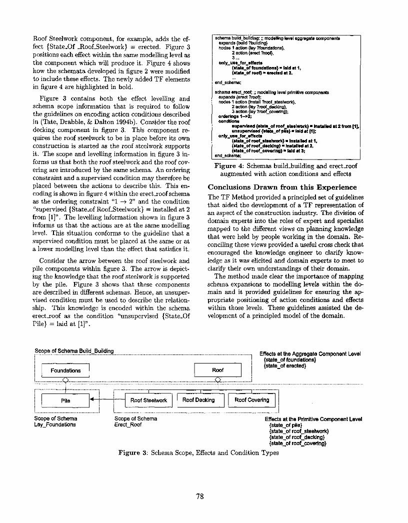
Roof Steelwork component, for example, adds the ef-fect {State_Of _Roof_Steelwork} = erected. Figure 3positions each effect within the same modelling level asthe component which will produce it. Figure 4 showshow the schemata developed in figure 2 were modifiedto include these effects. The newly added TF elementsin figure 4 are highlighted in bold.
Figure 3 contains both the effect levelling andschema scope information that is required to followthe guidelines on encoding action conditions describedin (Tate, Drabble, & Dalton 1994b). Consider the roofdecking component in figure 3. This component re-quires the roof steelwork to be in place before its ownconstruction is started as the roof steelwork supportsit. The scope and levelling information in figure 3 in-forms us that both the roof steelwork and the roof cov-ering are introduced by the same schema. An orderingconstraint and a supervised condition may therefore beplaced between the actions to describe this. This en-coding is shown in figure 4 within the erect_roof schemaas the ordering constraint "1 ~ 2" and the condition"supervised {State_of Roof_Steelwork} = installed at 2from [1]". The levelling information shown in figure 3informs us that the actions are at the same modellinglevel. This situation conforms to the guideline that asupervised condition must be placed at the same or ata lower modelling level than the effect that satisfies it.
Consider the arrow between the roof steelwork andpile components within figure 3. The arrow is depict-ing the knowledge that the roof steelwork is supportedby the pile. Figure 3 shows that these componentsare described in different schemas. Hence, an unsuper-vised condition must be used to describe the relation-ship. This knowledge is encoded within the schemaerect_roof as the condition "unsupervised {State_OfPile} = laid at [1]".
schema build_building; ;; modelling level aggregate componentsexpands {build ?building}nodes 1 action {lay ?foundations},
2 action {erect ?roof},3 ,..
only_use_for_effects{state_of foundations} ¯ laid at 1,{stata..of roof} ̄ erected at 2.
end_schema;
schema erect roof; ;; modelling level pdmltlva componentsexpands {erect ?roof};nodes I action {install ?rcof_steelwork},
2 action {lay ?roof.decking),3 action {lay ?roof..covedng};
ardarlngs 1-->2;condtlons
supervised (state_of roof..ataelw()rk) Installed at2 from [1],unsupervised {state_of pile} ¯ laid at [1];
only_use_for_affects(state_of roof_steelwork} ¯ installed at 1,{stata of roof_decking} ¯ Installed at 2,{state.of roof_covering} ¯ laid at 3;
and_schema;
Figure 4: Schemas build_building and erect_roofaugmented with action conditions and effects
Conclusions Drawn from this Experience
The TF Method provided a principled set of guidelinesthat aided the development of a TF representation ofan aspect of the construction industry. The division ofdomain experts into the roles of expert and specialistmapped to the different views on planning knowledgethat were held by people working in the domain. Re-conciling these views provided a useful cross check thatencouraged the knowledge engineer to clarify know-ledge as it was elicited and domain experts to meet toclarify their own understandings of their domain.
The method made clear the importance of mappingschema expansions to modelling levels within the do-main and it provided guidelines for ensuring the ap-propriate positioning of action conditions and effectswithin those levels. These guidelines assisted the de-velopment of a principled model of the domain.
ScoPe...°f-S-che-ma-Bu-!.!d...-Bu.!!d!n-g. .....................................................................................................................................................Effects at the Aggregate Component Leveli {state_.of foundations}
Foundations Roof{state_of erected}
il .,,o I-’, i l oo. ,oo.wo. l oo,oo0 ,n oo.cov°.n+!~ ~ ! J .....Scope of Schema Scope of Schema Effects at the Primitive Component LevelLay_Foundations Erect_Roof {state_of pile}
{state_of roof_steelwork}{state_of roof_decking}{state_of roof_covering}
Figure 3: Schema Scope, Effects and Condition Types
78

The weakness of the method is the absence of toolsupport. The knowledge engineer must use pencil andpaper to construct and maintain the figures shown inthis section. Tools can be provided to automaticallyshow the scope of schemas, highlight the levels of ef-fects relative to a particular condition, and warn theknowledge engineer when the guidelines for relatingcondition types to modelling levels are violated.
Common Process Editor
Recent research on a Common Process Framework(CPF) is seeking to facilitate process management in business and manufacturing application using AI plan-ning representations. This framework includes toolsupport via a Common Process Editor (CPE) whichacts as both the process visualisation and domain man-agement tool for users. An example screen shot fromthe Common Process Editor (CPE) is shown in ap-pendix A. Connection to an intelligent planning agent(e.g. O-Plan) allows for system-supported generationof business and manufacturing processes. A CommonProcess Assistant (CPA), which is also accessed as agent, is used to perform analyses of the processes.
The language used to communicate between theCPE and the planning agent is currently the TaskFormalism. This has provided us with insights intothe use of TF as part of an integrated process manage-ment system. A defined TF Method may be adaptedfor use in structuring of activities related to the design,modelling, and maintenance of these processes. Thistool-based assistance will help address the missing sup-port mentioned in section 3.5.
Related Domain ResearchA number of recent efforts in the AI planning researchcommunity have produced a variety of representations,approaches, tools, and architectures for working withAI planning domains. These range from machine learn-ing approaches to user-based knowledge acquisitiontools. This section samples some of the scope of ideaswhich may be utilised to provide a more effective meth-odology. We briefly present each approach in terms ofits contribution and then discuss some of the possibleissues.
A Formalisation of HTN Planning (Erol1995)¯ Contributions: Formal representation of Hierarch-
ical Task Network (HTN) planning that gives a clearunderstanding of what the different constructs andcondition types mean. This gives the knowledge en-gineer a formal underpinning which they may con-sult to clarify precisely the operation of different fa-
cets of an HTN planner and how the constructs sup-ported by HTN representational devices affect thisoperation. This work also presents a list of steps tofollow when encoding a domain description.
¯ Issues: The work is only accessible to AI planningspecialists and cannot be readily understood by do-main experts. It does, however, provide a founda-tion for understanding HTN planning that planningspecialists can use to guide them in the writing ofuser oriented methods like the guidelines in the TFmanual.
An Object-centred Specification Approach(McCluskey & Porteous 1997)
¯ Contributions: The authors seek to provide sup-port for constructing planning domain descriptionsby adapting methodological steps and notations ofthe object-oriented community. This approach util-ises the notion of "lifting" domain representationfrom the level of the literal to the level of the ob-ject. Once a domain has been described in termsof a state transition graph, the author’s algorithmscompile the diagram into a STRIPS (Fikes & Nilsson1971) style action representation.
¯ Issues: This work assumes that a domain can bedescribed as a state transition graph (STG). Thetechnique cannot currently generate HTN represent-ations. This might be possible if it is extended toinclude techniques which use hierarchies of STGs.However, there does not appear to be a mechanismfor inferring condition types.
Domain Analysis Techniques and Tools(Chien 1996)¯ Contributions: Chien provides two types of tools for
planning knowledge base development: static KBanalysis techniques to detect certain classes of syn-tactic errors and completion analysis techniques toiteratively debug the planning knowledge base. Thistool set supports typical user questions when invest-igating these types of error.
¯ Issues: The tool set can only be used after a signi-ficant proportion of a domain description has beenelicited. It doesn’t directly address how this initialdescription is to be constructed. Some AI plannersmay already perform such forms of domain checkingduring domain compilation.
Automatically Learning Operators (Wang1996)
¯ Contribution: Takes a set of example plans describedin terms of the actions in each plan and the state of
79

the world before and after each action. The systemexamines these examples and generates the precon-ditions and effects of operator descriptions.
¯ Issues: The technique assumes that the user canprovide example plans described in terms of the stateof the world before and after each action. It providesno assistance for the construction of these exampleplans. Again, the technique is only applicable toSTRIPS style planning not HTN.
A number of other contributions from the AI plan-ning community may be useful sources for the develop-ment of the TF Method as well. These works includearchitectures, such as the EXPECT knowledge acquis-ition architecture (Swartout & Gil 1996) which dynam-ically forms expectations about the knowledge thatneeds to be acquired by the system and then uses theseexpectations to interactively guide the user throughthe knowledge acquisition process. There are are alsospecialised techniques, for example, knowledge acquisi-tion on the fly (i.e. during planning) (desJardins 1996)and tools for editing operators and domain knowledge(e.g. Act editor (Myers & Wilkins 1997), Operatoreditor (desJardins 1996), etc.).
Integrating with Other Research Areas
An increasing number of requirements are being placedon both domain representations and the processes inwhich these artifacts are created, maintained etc. aswe forge ahead toward future implementations of arti-ficial intelligence planning systems. Domain develop-ment methods require solid modelling techniques andwell-defined, accepted concepts and terminology. As-pects of the domain may be linked to a specific set ofpossibly dynamic requirements. Modifications to thedomain throughout its life-cycle may require contex-tual knowledge which expresses the rationale for par-ticular domain design decisions.
Some of these issues facing applied planning effortsare being addressed by related research areas. Theseareas may provide sources of techniques, methods andguidelines which can be combined with AI domain de-velopment approaches to provide a more robust meth-odology. We briefly outline four possible researchareas: knowledge modelling, ontology engineering, re-quirements engineering, and design rationale.
Knowledge Modelling
Several approaches have been developed to tackle AIplanning problems (Allen, Hendler, & Tate 1990).While the result is a rich corpus of techniques andmethods, it is proving to be a very difficult task to com-pare and contrast each approach. Some researchers be-lieve the best way is to chart these results with detailed
algorithmic treatment (Kambhampati, Knoblock, & Q.1995). Barros, Valente, and Benjamins present a dif-fering perspective whereby the focus is on an abstractanalysis which highlights the capabilities of the systemand the way it represents and uses knowledge (Barros,Valente, & Benjamins 1996).
This knowledge modelling research utilises the Com-monKADS (Wielinga et al. 1992; Breuker & van deVelde 1994) methodology which outlines a set of de-tailed models to be created for an analysis. The AIplanning community has gained a more informed per-spective on the ways knowledge is used in variousplanning systems via the application of these meth-ods (Jarvis 1997; Barros, Valente, & Benjamins 1996;Kingston, Shadbolt, & Tate 1996; Cottam et al. 1995;Valente 1995). A hybrid domain life-cycle methodo-logy that integrates these model-building techniquesalong with the current methods and guidelines fromAI planning domain development could aid in liftingthe domain engineers level of interaction with the do-main and improve the overall construction process.
Ontology Engineering
Planning domain ontologies are specifications of theconcepts, terms, relations, etc. that form the basic lan-guage used to describe a domain (Valente 1995). Thesespecifications or definitions, expressed either inform-ally or formally (Uschold & Gruninger 1996), help clarify the semantics of the planning domain concepts.Domain ontologies, along with domain-independentontologies (cf. (Tate 1996c; 1996b)), characterise ments in the planning world model separately from anyparticular system that is reasoned about (generativeplanning system, plan evaluation system, etc.). Shareddomain ontologies (i.e. two or more systems/groupsagree to defined terminology) assist in breaking downsome of the arbitrary differences at the knowledge leveland facilitate knowledge sharing (Neches et al. 1991).
A methodology which seeks to address the construc-tion of plan domain models in an environment whereknowledge sharing is required must somehow be con-nected or combined with a methodology for building ashared domain ontology. Recent ontological engineer-ing research has begun to address the design and de-velopment of such methodologies (Fernandez, GSmez-P~rez, & Juristo 1997; GSmez-P~rez, Fern~dez, &Vicente 1996; Mizoguchi, Vanwelkenhuysen, & Ikeda1995). For example, GSmez-P~rez et. al. propose thefollowing set of phases (GSmez-P~rez, Fern£ndez, Vicente 1996)
¯ Acquire Knowledge
¯ Build a requirements specification document
8O

¯ Conceptualise the ontology
¯ Implement the ontology
¯ Evaluation during each phase
¯ Documentation after each phase
Some researchers propose general guidelines or tech-niques, such as a "middle-out" approach (Uschold Gruninger 1996) in which a glossary of terms is usedto define an initial set of primitive concepts which, inturn, are used to define new ones. Other researcherspropose more domain-specific approaches such as theontology building process utilised for disturbance dia-gnosis and service recovery planning in electrical net-works (Bernaras, Laresgoiti, & Corera 1996). Tech-niques developed in these projects may be candidatesfor integration into a planning domain developmenttool-box.
Requirements EngineeringSignificant work in requirements engineering has beenmade since the early O-Plan research into adopting theCORE methodology for use in planning domain devel-opment. This includes work on viewpoint managementand stake-holder analysis (Easterbrook & Nuseibeh1996; Kotonya & Somerville 1996; Finkelstein et al.1994), as well as work on various methodologies, tech-niques, and guidelines (Sommerville & Sawyer 1997;van Lamsweerde & Letier 1998) for eliciting, record-ing, and managing requirements.
Connecting domain aspects to their underlying re-quirements may assist in managing domain modific-ations which are the result of changing needs of anorganisation. Clearly defined roles and responsibilitiesat the requirement level will help to organise the activ-ities at the domain level. This will help to address oneof the major impediments which has prevented the ad-option of AI planning tools and techniques in appliedsettings: a lack of organisational context.
Design Rationale
A design rationale is a representation of the reasoningbehind the design of a system (Shum 1991). It is essen-tially the explicit recording of the issues, alternativesand justifications that were relevant to elements in thedesign of an artifact. Examples of design rationale im-plementations include: QOC (MacLean et al. 1991),DRL (Lee 1990), gIBIS (Conklin & Begeman 1988).
Large plan domains utilised within organisations canbe viewed as complexly designed artifacts. These ar-tifacts are managed, reviewed, and maintained just asinformation systems are. A methodology which en-compasses the development of such artifacts may need
to support the recording and replay of the rationalefor the decisions taken during its design. In a recentreview of planning rationale, we described a methodfor incorporating design rationale in planning (Polyak& Tate 1998). We believe that the benefits of a designrationale approach (Moran & Carroll 1996), will aid the reasoning, analysis and communication of planningdomain knowledge.
Summary
This paper has presented perspectives on an initialframework which will assist in the process of model-ling and analysing planning domains. These perspect-ives are based on past and present research efforts in:the TF guidelines; TF workstation; and integratingwith a requirements engineering methodology, experi-ence acquired in working with TF domains and insightsgained through the other efforts of planning, know-ledge modelling, ontology and requirements engineer-ing, and design rationale research groups. We believethat a synthesis of the techniques and methods foundin these works will be essential for improving the qual-ity of AI planning domain management throughout itsorganisational life-cycle.
Acknowledgements
The O-Plan project is sponsored by the Defence Ad-vanced Research Projects Agency (DARFA) and thec.s. Air Force Research Laboratory (AFRL), undergrant number F30602-95-1-0022. The O-Plan pro-ject is monitored by Dr. Northrup Fowler III at AFRL(Rome). One author is sponsored by the Air ForceOffice of Scientific Research, Air Force Materiel Com-mand, USAF, under grant number F49620-96-1-0348- an AASERT award monitored by Dr. Abe Waks-man and associated with the O-Plan project. The u.s.Government is authorised to reproduce and distributereprints for Governmental purposes notwithstandingany copyright annotation hereon. The views and con-clusions contained herein are those of the authors andshould not be interpreted as necessarily representingofficial policies or endorsements, either express or im-plied, of DARPA, AFRL or the u.s. Government.
References
Allen, J.; Hendler, J.; and Tate, A., eds. 1990. Read-ings in Planning. Palo Alto, CA: Morgan Kanfmann.
Barros, L.; Valente, A.; and Benjamins, R. 1996.Modeling planning tasks. In Proceedings of theThird International Conference on Artificial Intelli-gence Planning Systems (AIPS-96), 11-18. Edin-burgh, Scotland: Morgan Kaufmann.
81
Bernaras, A.; Laresgoiti, I.; and Corera, J. 1996.Building and reusing ontologies for electrical networkapplications. In Proceedings o] the European Confer-ence on Artifical Intelligence (ECAI) ’96, 298-302.
Breuker, J., and van de Velde, W. 1994. The Com-monKADS Library ]or Expertise Modelling: reusablecomponents /or artificial problem solving. Amster-dam, Tokyo: IOS Press.
Chien, S. 1996. Static and completion analysis forplanning knowledge base development and verifica-tion. In Drabble (1996), 53-61.
Conklin, E., and Begeman, M. L. 1988. gIBIS: A hy-pertext tool for explanatory policy discussion. A CMTransactions on Office In/ormation Systems 6:303-331.
Cottam, H.; Shadbolt, N.; Kingston, J.; Beck, H.;and Tate, A. 1995. Knowledge level planning in thesearch and rescue domain. In Research and Devel-opment in Expert Systems XII, proceedings o/ BCSExpert Systems’95.
Currie, K., and Tate, A. 1991. O-Plan: the openplanning architecture. Artificial Intelligence 52:49-86.
Curwen, P. 1991. System development us-ing the CORE method. Military Aircraft Ltd.BAe/WIT/ML/GEN/SWE/1227, British Aerospace,PLC, Warton Aerodrome, Preston, UK.
desJardins, M. 1996. Knowledge acquisition tools forplanning systems. In Tate (1996a), 53-61.
Drabble, B., ed. 1996. Proceedings of the Third Inter-national Con]erence on Artificial Intelligence Plan-ning Systems (AIPS-96). Edinburgh, Scotland: Mor-gan Kaufmann.
Drummond, M. 1994. On precondition achievementand the computational economics of automated plan-ning. In Backstrom, C., and Sandewall, E., eds., Cur-rent Trends in AI Planning. IOS Press. 6-13.
Easterbrook, S., and Nuseibeh, B. 1996. Using view-points for inconsistency management. Soft. Engin.Journ. January.
Erol, K. 1995. Hierarchical Task Network Planning:Formalisation, Analysis, and Implementation. De-partment of computer science, University of Mary-land, College Park, USA.
Fern£ndez, M.; GSmez-P@rez, A.; and Juristo, N.1997. Methontology: From ontological art towardsontological engineering. In Workshop on OntologicalEngineering, Spring Symposium Series, AAAIgZ
Fikes, R., and Nilsson, N. 1971. STRIPS: A newapproach to the application of theorem proving toproblem solving. Artificial Intelligence 2:189-208.
Finkelstein, A.; Gabbay, D.; Hunter, A.; Kramer, J.;and Nuseibeh, B. 1994. Inconsistency handling inmulit-perspective specifications. Trans Software Eng20(8):569-578.
G5mez-P@rez, A.; Fern£ndez, M.; and Vicente, A. D.1996. Towards a method to conceptualize domainontologies. In Workshop on Ontological Engineering,ECAI’96, 41-51.
Jarvis, P., and Winstanley, G. 1996a. Dynamicallyassessed and reasoned task (DART) networks. In Pro-ceedings o] the Sixteenth Annual Technical Conferenceo/ the British Computer Society Specialist Group onExpert Systems (ES-96), Cambridge, UK.
Jarvis, P., and Winstanley, G. 1996b. Objects andobjectives: the merging of object and planning tech-nologies. In Proceedings o] the Fifteenth Workshopo] the UK Planning and Scheduling Special InterestGroup, Liverpool, UK.
Jarvis, P., and Winstanley, G. 1998. Reducing thesemantic gap between application domains and AIplanning technology: a compilation based approach.In Workshop on Knowledge Acquisition and Know-ledge Elicitation, to be held within the Fourth Interna-tional Conference on Artificial Intelligence PlanningSystems, Pittsburgh, USA.
Jarvis, P. 1997. Integration of Classical and Model-Based Planning. PhD thesis, School of Computingand Mathematical Sciences, University of Brighton,Sussex, UK.
Kambhampati, S.; Knoblock, C.; and Q., Y. 1995.Planning as refinement search: a unified frameworkfor evaluating design tradeoffs in partial-order plan-ning. Artificial Intelligence 76.
Kingston, J.; Shadbolt, N.; and Tate, A. 1996. Com-monKADS models for knowledge based planning. Ar-tificial Intelligence Application Institute AIAI-TR-199, University of Edinburgh, Edinburgh, Scotland.
Kotonya, G., and Somerville, I. 1996. Requirementsengineering with viewpoints. Soft. Engin. Journ.II(I).
Lee, J. 1990. SIBYL: A qualitative decision manage-ment system. In Winston, P., and Shellard, S., eds.,Artificial Intelligence at MIT: Expanding Frontiers.MIT Press. 104-133.
MacLean, A.; Young, R.; Bellotti, V.; and Moran, T.1991. Design space analysis: Bridging from theory to
82

practice via design rationale. In Proceedings of Esprit’91, 720-730.
McCluskey, T., and Porteous, J. 1997. Engineeringand compiling planning domain models to promotevalidity and efficiency. Artificial Intelligence 95(1):1-65.
Mizoguchi, R.; Vanwelkenhuysen, J.; and Ikeda, M.1995. Task ontology for reuse of problem solv-ing knowledge. In Towards Very Large KnowledgeBases: Knowledge Building and Knowledge Sharing.IOS Press. 46-59.
Moran, T., and Carroll, J., eds. 1996. Design Ra-tionale: Concepts, Techniques, and Use. LawrenceErlbaum Associates.
Mullery, G. 1979. CORE: A method for controlledrequirements specification. In Proceedings of the ~thInternational Conference on Software Engineering.
Myers, K., and Wilkins, D. 1997. The act-editoruser’s guide: A manual for version 2.2. SRI Interna-tional Artificial Intelligence Center, Stanford Univer-sity, Menlo Park, CA.
Neches, R.; Fikes, R.; Finin, T.; Gruber, T.; Patil,R.; Senator, T.; and Swartout, W. 1991. Enablingtechnology for knowledge sharing. AI Magazine Fall.
Polyak, S., and Tate, A. 1998. Rationale in planning:Causality, dependencies, and decisions. KnowledgeEngineering Review 13(2):1-16.
Shum, S. 1991. Cognitive dimensions of design ra-tionale. In Diaper, D., and Hammond, N., eds.,People and Computers VI, 1-13. Cambridge: Cam-bridge University Press.
Sommerville, I., and Sawyer, P. 1997. RequirementsEngineering: A Good Practice Guide. John Wiley andSons.
Stephens, J., and Whitehead, R. 1984. The analyst -an expert system approach to requirements analysis.In Proceeding of the third seminar on Application ofMachine Intelligence to Defence Systems.
Swartout, W., and Gil, Y. 1996. EXPECT: A user-centered environment for the development and ad-aptation of knowledge-based planning aids. In Tare(1996a), 250-258.
Tate, A., and Currie, K. 1984. The O-Plan taskformalism workstation. Artificial Intelligence Applic-ations Institute (AIAI) AIAI-TR-7, University of Ed-inburgh.
Tate, A., and Currie, K. 1985. The O-Plan task form-alism workstation. In Proceedings of the Third Work-shop of the UK Alvey Programme’s Planning Special
Interest Group. London, UK: Institute of ElectricalEngineers.
Tate, A.; Drabble, B.; and Dalton, J. 1994a.Task formalism manual. Artificial Intelli-gence Applications Institute AIAI-TF-Manual,University of Edinburgh, Edinburgh, UKftp: / / ftp.aiai.ed.ac.uk /pub /documents /ANY / oplan-tf-manual.ps.gz.
Tare, A.; Drabble, B.; and Dalton, J. 1994b. The useof condition types to restrict search in an AI planner.In Proceedings of Twelfth National Conference on AI(AAAI-94), Seattle.
Tate, A. 1977. Generating project networks. In Pro-ceedings of the International Joint Conference on Ar-tificial Intelligence (IJCAI- 77), 888-893.
Tare, A., ed. 1996a. Advanced Planning Technology:Technological Advancements of the ARPA/RomeLaboratory Planning Initiative. Menlo Park, CA:AAAI Press.
Tate, A. 1996b. Representing plans as a set of con-straints - the < I-N-OVA > model. In Drabble (1996),221-228.
Tate, A. 1996c. Towards a plan ontology. AI*IANotiziqe (Publication of the Associazione Italiana perl’InteUigenza Artificiale), Special Issue on Aspects ofPlanning Research 9(1):19-26.
Uschold, M., and Gruninger, M. 1996. Ontologies:Principles, methods and applications. Knowledge En-gineering Review 11(2).
Valente, A. 1995. Knowledge-level analysis of plan-ning systems. SIGART Bulletin 6(1).
van Lamsweerde, A., and Letier, E. 1998. Integratingobstacles in goal-driven requirements engineering. InProceedings (ICSE’98) - 20th International Confer-ence on Software Engineering, (IEEE-ACM).
Wang, X. 1996. Planning while learning operators.In Drabble (1996), 229-236.
Wielinga, B.; van de Velde, W.; Schriber, G.; and Ak-kermans, H. 1992. The KADS knowledge modellingapproach. In Proceedings of the Japanese KnowledgeAcquisition Workshop.
Wilkins, D. 1988. Practical Planning: Extending theClassical AI Planning Paradigm. Morgan Kaufmann.
Wilson, A. 1984. Information for Planning. M.Sc.Thesis, Department of Artificial Intelligence, Univer-sity of Edinburgh, UK.
83

Sample Graphical User Interface Screens
These two screen shots are examples from the TF workstation (top, 1984) and the Common Process Editor (CPE)(bottom, 1998) which provide tool-supported assistance for plan/process management.
:m
84
![A Survey on Usage Scenarios for Requirements Traceability ... · traceability support that suits practical needs [21]. With traceability practice, we mean the way in which traceability](https://img.dokumen.tips/doc/110x75/5ecd70c9403ddd79964b64ed/a-survey-on-usage-scenarios-for-requirements-traceability-traceability-support.jpg)