Embed Size (px)
Citation preview

Texture Mapping 3D Models of Real-World ScenesFREDERICK M. WEINHAUS
ESL
AND
VENKAT DEVARAJAN
University of Texas at Arlington
Texture mapping has become a popular tool in the computer graphics industry inthe last few years because it is an easy way to achieve a high degree of realism incomputer-generated imagery with very little effort. Over the last decade, texture-mapping techniques have advanced to the point where it is possible to generatereal-time perspective simulations of real-world areas by texture mapping everyobject surface with texture from photographic images of these real-world areas.The techniques for generating such perspective transformations are variations ontraditional texture mapping that in some circles have become known as theImage Perspective Transformation or IPT technology. This article first presents abackground survey of traditional texture mapping. It then continues with adescription of the texture-mapping variations that achieve these perspectivetransformations of photographic images of real-world scenes. The style of thepresentation is that of a resource survey rather than an in-depth analysis.
Categories and Subject Descriptors: I.3.3 [Computer Graphics]: Picture/ImageGeneration—antialiasing; I.3.5 [Computer Graphics]: Computational Geometryand Object Modeling–curve, surface, solid, and object representations; hierarchyand geometry transformations; I.3.7 [Computer Graphics]: Three-DimensionalGraphics and Realism–color, shading, shadowing, and texture; hidden line/surfaceremoval; raytracing
General Terms: Algorithms
Additional Key Words and Phrases: Anti-aliasing, height field, homogeneouscoordinates, image perspective transformation, image warping, multiresolutiondata, perspective projection, polygons, ray tracing, real-time scene generation,rectification, registration, texture mapping, visual simulators, voxels
INTRODUCTION
The computer graphics industry hasmade dramatic advances during the last
decade in the creation of ever more real-istic looking images. Techniques havebeen developed to generate illumina-tion-based shading effects, shadows, re-
Authors’ addresses: F.M. Weinhaus, 925 Wolfe Rd. #52, Sunnyvale, CA 94086; email ^[email protected]&;V. Devarajan, Electrical Engineering Department, University of Texas, Arlington, TX 76019; email^[email protected]&.ESL is now TRW, Sunnyvale, CA 94088.Permission to make digital / hard copy of part or all of this work for personal or classroom use is grantedwithout fee provided that the copies are not made or distributed for profit or commercial advantage, thecopyright notice, the title of the publication, and its date appear, and notice is given that copying is bypermission of the ACM, Inc. To copy otherwise, to republish, to post on servers, or to redistribute tolists, requires prior specific permission and / or a fee.© 1997 ACM 0360-0300/97/1200–0325 $03.50
ACM Computing Surveys, Vol. 29, No. 4, December 1997

flection, refraction, motion blur, lens de-focus, and such natural phenomena assky, clouds, haze, fire, trees, grass, andwater waves. Some of these techniqueshave even been incorporated into flightand vehicle simulators such as thosebuilt by General Electric Controls &Guidance Systems Division (now Lock-heed-Martin Co. Orlando, FL), Evans &Sutherland, and others. Unfortunately,many of these techniques are too com-putationally intensive for such real-time applications. For a survey of syn-thetic scene generation techniques, see,for example, Magnenat-Thalmann andThalmann [1987].
Today, more demands are beingplaced upon visual simulators toachieve yet a higher level of realism[Fischetti and Truxal 1985; Tucker1984]. In particular, mission planningand rehearsal systems are now strivingfor truly faithful representations so thatground troops can become intimately fa-miliar with important regions of theworld [Geer and Dixon 1988]. This levelof detail and realism is possible only byusing digitized photographs of the areasof interest.
The technology is available today. Ex-amples have already been presented tothe general public in the form of moviesat conferences and on public television,and the like. The Jet Propulsion Labo-ratory has made several of these mov-ies. Two of these are fly-overs, called“LA—The Movie” [Hussey et al. 1987]and “Mars—The Movie,” [Hall 1989],which were presented at SIGGRAPHconferences and on PBS television. Athird one depicts travel along the SanAndreas fault in California [Stanfill1991]. It has been shown as part of thefilm, “The Blue Planet,” at IMAXt andOMNIMAXt theaters worldwide. A dif-ferent fly-around of California was gen-erated by ESL (now TRW, Sunnyvale,CA) and was shown at the 1988 World’sFair in Australia.1 Another example isthe video of the Calgary area that was
created by The Analytical Sciences Cor-poration for ABC News and Sports [Mc-Millan 1988; Gelberg et al. 1988]. It wasshown during the 1988 Winter Olym-pics. Also a fly-around of Mt. Everestwas created by Visual InformationTechnologies (VITec, now ConnectwareInc.). It was shown as part of the 1991NOVA program, “Taller Than Everest?”Finally, Volotta Interactive Video hasput together a system, called the MarsNavigator [Volotta 1991], to present lowaltitude, computer-generated fly-bys ofthe surface of Mars prepared by AppleComputer [Hughes 1991] from Vikingorbiter imagery. This system is on dis-play at the Tech Museum of Innovationin San Jose.
The techniques used to make suchimages and movies are variations of thecomputer graphics technique called tex-ture mapping. They have also come tobe known by such names as image per-spective transformations (IPT), 2.5Dimage transformations, and perspectivephoto mapping. The first name comesfrom its origins in image processing,remote sensing, and photogrammetry.The second name reflects the fact thatthe transformation is between two-di-mensional (2D) and three-dimensional(3D); that is, the resulting views ac-count for perspective depth, but are nottruly three-dimensional in the sense offull stereoscopic viewing. The thirdname has been coined to show its exten-sion from traditional texture mapping.
Some of the salient challenges thatmust be met to achieve these imagesand movies and to create effective vi-sual simulations include:
(1) How to create high resolution mod-els from heterogeneous inputsources such as magazine pictures,direct photography, digital imagery,artists renderings, and the like.
(2) How to align or register the imagerywith the geometry models andsmoothly blend different modelsfrom different sources so that noth-ing stands out unnaturally.
1 Produced under the technical leadership of JohnThomas at ESL.
326 • F.M. Weinhaus and V. Devarajan
ACM Computing Surveys, Vol. 29, No. 4, December 1997

(3) How to deal efficiently with verylarge databases to keep renderingtimes down while maintaining real-ism.—Geometry models may include
both natural terrain and urbanfeatures, where the former maycontain millions of (regularly orirregularly spaced) elevation val-ues.
—Many large, oblique, high-resolu-tion images may be needed tocover the vast expanse of naturalterrain.
(4) How to correct source imagery dis-tortions so that resulting outputviews are faithful.—Source images are often oblique
views.—Source images are formed by vari-
ous camera and sensor types oftenwith nonstandard geometries.
(5) How to prewarp the output imagesso they project naturally ontodomes, pancake windows, and thelike.
(6) How to perform these myriad tasksfast enough for real-time or highspeed nonreal-time display.
For the purposes of discussion in thisarticle, we refer to the texture-mappingvariations that attempt to solve some or
all of these challenges as the imageperspective transformation. Althoughthe distinction between the IPT texture-mapping variation and traditional tex-ture mapping may be subtle, these dif-ferences are worth noting. Some peoplemay argue that they are fundamentallyjust differences in terminology arisingfrom the perspectives of the disciplinesthat originated them; namely, imageprocessing, remote sensing, and photo-grammetry in the former case and com-puter graphics in the latter case. To alarge extent this is true, especially withregard to the basic objectives, namely,to transfer image texture onto the sur-faces of 3D models. Moreover, the twotechnologies are rapidly converging.Nevertheless, some of the conceptualdifferences are worth emphasizing aswell as some of the novel algorithmicapproaches that have been developedthat are quite different from the basicpolygon-based approach used in tradi-tional texture mapping. Consequently,some of the important differences be-tween the image perspective transfor-mation and the traditional texture-map-ping technique are summarized in thefollowing and listed in Table 1. A math-ematical treatise of traditional and pro-jective texture mapping is presented inWeinhaus and Devich [1997].
Table 1. Comparison of Traditional Texture Mapping with IPT
Traditional Texture Mapping Image Perspective Transformation
● Texture maps are frequently synthetic ● Texture maps are actual photographs orremote sensing images of real-world areas
● Relatively few small texture maps are used ● Many large images are used as texture maps● Texture maps are frequently repeated on
multiple objects or faces● Textures are unique per object face
● Texture maps are typically face-on views ● Texture maps are typically oblique views● Textures are often arbitrarily mapped onto
objects without concern for distortions● Photogrammetry techniques are often used to
project the textures onto object faces to correctfor camera acquisition geometry
● Alignment of texture maps with the objectfaces is generally done manually
● Photogrammetric/remote sensing techniquesare frequently used to automatically align thetextures with the object faces
● 3-D object models are typically builtindependently from the texture maps
● Photogrammetry techniques are frequentlyused to build 3-D object models of terrain andurban structures from the imagery
● Polygon object models and renderingapproaches are typically used
● Height field, voxel and polygon object modelsand rendering approaches are all used
Texture Mapping 3D Models • 327
ACM Computing Surveys, Vol. 29, No. 4, December 1997

With traditional texture-mappingtechniques, texture patterns are mathe-matically transferred first onto the sur-faces of 3D models that are used torepresent either fictitious or real-worldscenes. Then, from this intermediateformat, they are perspectively projectedonto the output viewing plane. Usually,these texture patterns are computer-synthesized ones representing genericsurface materials such as grass or wood,or they are digitized photographs of rep-resentative materials viewed face-onsuch as brick or concrete. Sometimes,they are even photographs of real-worldscenes used to represent backdrops,views out of windows, reflection pat-terns of the surrounding scene, or pic-tures to be incorporated on interiorwalls of rooms. These texture patternstypically are mapped orthogonally ontoplanar object faces with a simple affinetransformation. However, for certainapplications, they either may be pre-warped or treated as a parametric rep-resentation of a coordinate system suchas cylindrical or spherical in order towrap them about an object conformingto the same geometry. Texture tiling[Dungan et al. 1978], cell texturing[Economy and Bunker 1984; Bunker etal. 1984], decal mapping [Barr 1984],reflection mapping [Blinn and Newell1976], and environment mapping[Green 1986] are some of the specificnames used to describe variations of thetexture mapping technique.
With the IPT technique, the texturesalso come from digitized photographs;however, in this case, the texture pat-terns are the complete and often obliquephotographs of real-world areas thatare represented by the 3D models. Theobjective is to start from a set of sourcephotographs and create new views ofthe real-world areas from arbitrary van-tage (eye) points and, if possible, to doso in real-time (i.e., 30 or 60 frames persecond).
For the traditional texture-mappingcase, one generally uses only a limitednumber of relatively small texture pat-terns. Usually, one texture pattern is
defined to span the space of the surfacein question, since there is often a simplecorrespondence between the polygonalbounds of the texture pattern and thepolygonal shape of the surface. Some-times, however, a single texture patternmay be repeated to fill out the coverageof a surface or the same pattern may beassigned to many neighboring surfaces.In this context, a surface can be a pla-nar or nonplanar polygon, a nonplanarpatch, or even the complete surface of aquadratic object such as a cylinder orsphere. Thus, for example, it may bethat a texture pattern is arbitrarilystretched using a “rubber sheet” (affineor bilinear) transformation onto a pla-nar quadrilateral or parametricallywrapped about the surface of a cylindri-cally symmetric or spherical object. As aconsequence of the rather arbitrarymapping onto nonplanar objects, the re-sulting appearance of the texture cover-ing for the surface may be distorted.Nevertheless, this may not be notice-able due to the lack of real-world corre-spondence between the texture and themodel.
For the IPT case, many large photo-graphic texture images may be neededto cover large expanses of territory.Also, different portions of one or morephotographs must be mapped onto thenumerous surfaces that form the com-plex 3D models of the real-world area.This photographic information mustalign with the 3D models without dis-tortion and with minimal manual inter-vention. This is often accomplished as apreprocessing step using photogramme-try and remote sensing registrationtechniques. More optimally, the texture-mapping process should automaticallytake into account the acquisition geom-etry of the system that took the photo-graphs. For pictures acquired by aframe (snap-shot) camera system, thismapping must correct for perspectivedistortion inherent in the source imag-ery. This distortion causes obliquelyviewed rectangles to appear as quadri-laterals. For this camera system, twoperspective transformations are in-
328 • F.M. Weinhaus and V. Devarajan
ACM Computing Surveys, Vol. 29, No. 4, December 1997
volved: one to map the texture onto the3D models and one to project this inter-mediate result onto the output viewingplane. Photogrammetry equations areoften used to represent both of theseperspective transformations.
The objectives of this article arethreefold: to present the historical back-ground for the image perspective trans-formation technique starting with itsorigin in texture mapping, to introduceits mathematical foundation (a detailedmathematical treatise of texture map-ping can be found in Weinhaus andDevich [1997]), and to identify the vari-ous approaches that have been taken,giving credit to the many people andorganizations that have contributed toit. The emphasis of this article is pri-marily on the geometry of the transfor-mation; however, the issue of renderingquality is also addressed. Our approachto this survey, therefore, is to provideonly a simple description of the manytechniques that have been developed,citing references so that the user subse-quently may review them in more depthand formulate his or her own judgmenton their merits. Where appropriate, wepoint out the strengths and weaknessesof these approaches. However, it is notour intention to provide our biased se-lections of the “best” ones. Moreover, analgorithm that works well in a softwareenvironment may be quite inappropri-ate for hardware implementation.
In the material that follows, Section 2first reviews the history of traditionaltexture mapping. It then describes themathematical foundation and the devel-opment of texture-mapping approaches.Section 3 starts with a similar historicalreview for the image perspective trans-formation technology. It then reviewsthe IPT-specific approaches that havebeen developed, subdividing them intothree categories according to the waythe 3D model is represented: heightfields, voxels, and polygons/patches. InSection 4, nonreal-time and real-timesystems are discussed with emphasis onthe technology arising from the flightsimulator community.
2. TEXTURE MAPPING
2.1 Texture Mapping Background
The pioneering work in texture map-ping is generally attributed to Catmull[1975]. He was probably the first todemonstrate the mapping of a (brick)texture pattern onto arbitrary planarand cylindrical surfaces. Blinn andNewell [1976] then took the concept onestep further by mapping photographictextures onto a bicubic patch represen-tation of the now famous teapot. Aokiand Levine [1978] and Feibush et al.[1980] independently used the tech-nique to render synthetic textures ontothe faces of 3D models of houses. Fei-bush and Greenberg [1980] also devel-oped a texture mapping system to beused for architectural design. Later,Economy and Bunker [1984] and Bun-ker et al. [1984] introduced the conceptof computer-synthesized “cell” texturesto cover ground terrain in visual flightsimulators, and Dungan et al. [1978]applied actual photographic texture pat-terns to cover the ground terrain. In thelatter case, they acquired vertical pho-tographs of representative tree-coveredterrain from low-flying aircraft and pho-tographs of grass textures from modelboards. These texture patterns werethen mapped onto 3D polygonal terrainelevation models in their simulatedscenes. These authors were among thefirst to publish examples using textureswith multiple levels of resolution as amethod of anti-aliasing. Later, the sci-entists at General Electric [Economyand Bunker 1984; Bunker et al. 1984]and Honeywell [Scott 1983; Erickson etal. 1984] developed applications of tex-ture mapping of photographs of individ-ual trees onto planar “billboards” andonto multifaceted 3D models of individ-ual trees. Transparency effects were in-troduced to make the texture regionsaround the trees and between the leavesinvisible. Bunker et al. [1984] describedsimilar translucency techniques for in-serting texture patterns of cloud layersinto simulated scenes.
Texture Mapping 3D Models • 329
ACM Computing Surveys, Vol. 29, No. 4, December 1997

The geometry of texture mapping isdepicted in Figure 1. Two transforma-tions are involved. One transformationis between object space and texture (in-put) space and the other is betweenobject space and screen (output) space.The object space is characterized by theequation of each surface of the 3Dmodel. The object–texture transforma-tion may be as simple as an affine orbilinear transformation when the tex-ture is to be mapped orthogonally onto aplanar quadrilateral. Alternately, itmay be a parametric transformationwhen the texture coordinates are usedto represent nonCartesian coordinates,such as cylindrical or spherical, and thetextures are to be “shrink-wrapped”about a 3D model with like symmetry.Bier and Sloan [1986] have presented anumber of examples for this latter caseand Heckbert [1989] has discussed atlength various 2D transformations usedto map textures onto planar and nonpla-nar polygons. The object–screen trans-formation is usually either an ortho-graphic projection (sometimes called aparallel plane projection) or a (central)perspective projection. The former in-volves imaging with parallel rays andexhibits uniform scale. The latter in-volves imaging with rays that converge
to a focal point and exhibits scale thatvaries from foreground to background,that is, perspective foreshortening. Ta-ble 2 presents the form of some of thesekey transformation equations funda-mental to traditional texture mappingand the image perspective transforma-tion variation. In these equations asrelevant to the direction of the transfor-mation (forward or reverse), either (x, y,and optionally, z) or (X, Y, and option-ally Z) represents object space and theother represents either texture space(u, v) or screen space (S, L).
Often the object–texture and object–screen transformations are concate-nated in order to save computations.The resulting composite transformationusually can be formulated either as aforward (texture-to-screen) transforma-tion or as an inverse (screen-to-texture)transformation. Each has its own ad-vantages and disadvantages, whichhave been discussed at length by Heck-bert [1989] and by Wolberg [1990].
In general, anti-aliasing techniquesfor texture-mapping applications havebeen more elaborate than for the moretraditional coloring and/or illumination-based rendering techniques in order toaccommodate the combination of finedetail in photographic imagery and spa-
Figure 1. Texture-mapping geometry.
330 • F.M. Weinhaus and V. Devarajan
ACM Computing Surveys, Vol. 29, No. 4, December 1997

tially varying scale when viewing inperspective. Some of the more sophisti-cated techniques that have been used toanti-alias texture-mapped images arecited here for completeness. They in-clude the following: trilinear interpola-tion on hierarchical resolution texturepatterns (called pyramids [Tanimotoand Pavlidis 1975; Burt 1981] and MIPmaps [Williams 1983]), ellipticallyweighted averaging (EWA) [Greene andHeckbert 1986], spatially variant filter-ing [Fournier and Fiume 1988],summed area tables [Crow 1984; Glass-ner 1986], repeated integration [Heck-
bert 1986a], clamping [Norton et al.1982], super-resolution sampling, sto-chastic and jittered sampling [Cook1986; Dippe 1985], adaptive sampling[Painter and Sloane 1989], A-buffering[Carpenter 1984], accumulation-buffer-ing [Haeberli and Akeley 1990], andspatial transformation lookup tables[Walterman and Weinhaus 1991]. Heck-bert [1986b] has presented a review andcomparison of many of these anti-alias-ing techniques. Some of these are dis-cussed later in the context of the de-scription of a particular texturemapping or IPT algorithm.
Table 2. Key Transformation Equations*
Name Properties Form
AFFINE(LINEAR)
● Translation, Scale, RotationAnd Skew
x 5 A0 1 A1X 1 A2Y
● Preserves Straight Lines,Parallelism And ScaleHomogeneity
y 5 B0 1 B1X 1 B2Y
BILINEAR ● Preserves Straightness OfHorizontal & Vertical
x 5 A0 1 A1X 1 A2Y 1 A3XY
Linesy 5 B0 1 B1X 1 B2Y 1 B3XY
● Maps Other Straight LinesInto Hyperbolic Curves
QUADRATIC ● Maps Straight Lines IntoQuadratic Curves
x 5 A0 1 A1X 1 A2Y 1 A3XY 1 A4X2 1 A5Y2
y 5 B0 1 B1X 1 B2Y 1 B3XY 1 B4X2 1 B5Y2
CUBIC ● Maps Straight Lines IntoCubic Curves
x 5 A0 1 A1X 1 A2Y 1 A3XY 1 A4X2 1 A5Y2
1 A6X2Y 1 A7XY2 1 A8X3 1 A9Y3
y 5 B0 1 B1X 1 B2Y 1 B3XY 1 B4X2 1 B5Y2
1 B6X2Y 1 B7XY2 1 B8X3 1 B9Y3
PROJECTION● Perspective● Orthographic
● Preserves Straight Lines
1wxwywzw2 5 PRT1
XYZ12 where
MatricesP5projectionR5rotationT5translation
w is eliminated by dividing the 4thcomponent into the other three
P 5 11 0 0 00 1 0 00 0 1 00 0 1/f 1
2f 5 focal length for the perspective case(1/f) 5 0 and w 5 1 for the orthographiccase
* Shows the form of some of the transformation equations fundamental to traditional texture mappingand the image perspective transformation variation. In these equations, as relevant to the direction ofthe transformation (forward or reverse), either ( x, y, and optionally, z) or (X, Y, and optionally, Z)represent object space and the other represents either texture space (u, v) or screen space (S, L).
Texture Mapping 3D Models • 331
ACM Computing Surveys, Vol. 29, No. 4, December 1997

2.2 Texture Mapping Approaches
The fundamental, nontexture-mappedrendering technique used by most 3Dgraphics systems typically projects thevertices of each primitive (usually pla-nar polygons) from world coordinatesinto screen coordinates using a perspec-tive projection equation as shown in Ta-ble 2. It then linearly interpolates thecolor (and perspective depth) at eachedge and interior pixel of this projectedprimitive. Usually, an algorithm, suchas the digital differential analyzer(DDA) [Swanson and Thayer 1986;Pineda 1988] or forward difference tech-nique [Lien et al. 1987; Shantz and Lien1987] is used to do the interpolationfrom the color and perspective depthvalues stored for each vertex. Such algo-rithms are very efficient, since they ex-ploit incremental computations alongeach scan-line of the projected primi-tive. The well-known Gouraud shadingtechnique is an example of this type ofinterpolation where the shading infor-mation associated with the vertices isdetermined by an illumination model inconjunction with the vertex normals.The Phong shading technique is similar,but interpolates the vertex normals be-fore determining the shading value ateach interior pixel. See, for example,Rogers [1985] or Foley et al. [1993] formore details about these two specificshading techniques.
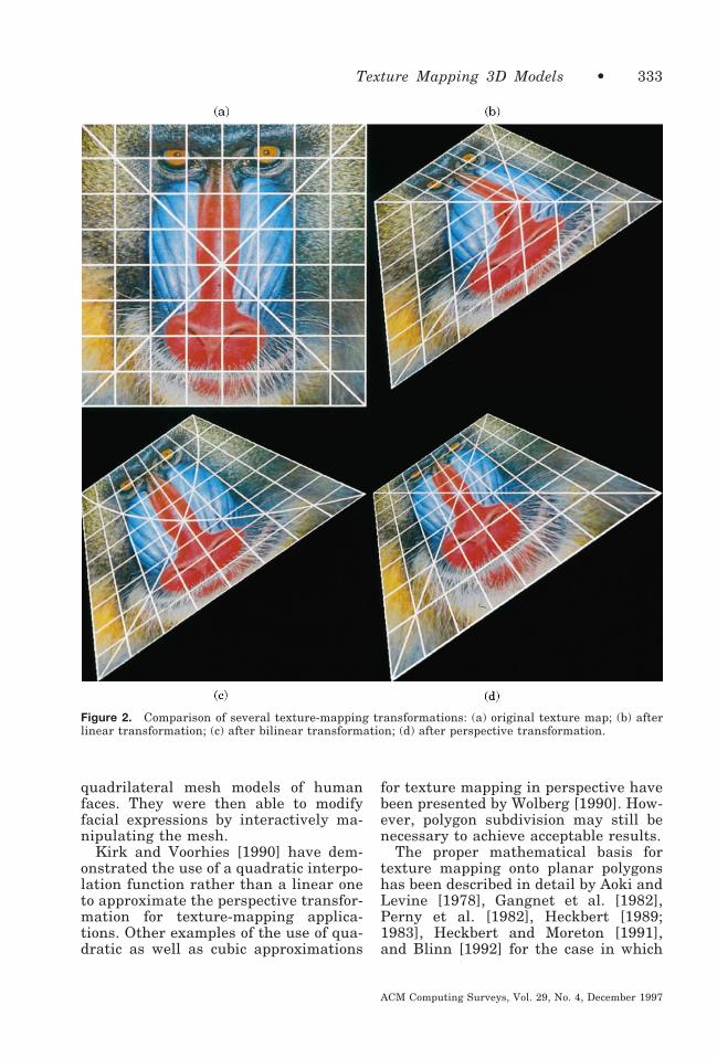
As pointed out by Heckbert and More-ton [1991] and by Blinn [1992], a naiveapproach to texture mapping wouldstore the corresponding texture coordi-nates for each vertex and try to inter-polate these coordinates in a similarmanner. The interpolated texture coor-dinates would then be used to index intothe texture image to extract the appro-priate color values. Unfortunately, thisprocedure introduces distortions thatmay be noticeable, because the tech-nique approximates the perspectiveprojection with a linear transformation.Moreover, polygons are usually subdi-vided into combinations of triangles andquadrilaterals that have one or two
edges aligned along the scan direction,respectively. Each triangle or quadrilat-eral ultimately will use a different lin-ear transformation. This may createsharp bends or folds in transformed lin-ear features as they pass from one sub-polygon to another. A demonstration ofthis effect is presented in Figure 2(b)where the quadrilateral has been subdi-vided along one of its diagonals into twotriangles. Since the other diagonal mustpass through the midpoint of the firstdiagonal, it will be transformed into twojoined line segments, each with differ-ent slopes. Figure 2(a) shows the origi-nal texture map.
To avoid such discontinuities forquadrilaterals, one might try using abilinear transformation rather than alinear one to interpolate the texture co-ordinates. Unfortunately, the bilineartransformation only preserves straightlines originally parallel to the coordi-nate axes of the texture map. Conse-quently, the diagonals will appearcurved in the resulting interpolatedpolygon. A proper perspective transfor-mation will preserve all straight lines.Demonstrations of these characteristicsare presented in Figures 2(c) and 2(d).These three transformations also affectscale differently. The linear and bilin-ear transformations preserve scaleacross the texture pattern better thanthe perspective transformation. This ef-fect can be observed in the figures byexamining the spacing of the grid pat-tern, especially between those lines thatcorrespond to the horizontal ones in theoriginal texture image. In Figure 2(d),this spacing progressively increasesfrom top to bottom, whereas, in Figures2(b) and 2(c), it remains constant.
Note that the linear approximationgets progressively better for smallerpolygons. Thus, Catmull’s [1975] ren-dering algorithm, which adaptively sub-divides surfaces into pixel-sized mi-cropolygons, is well suited to handlethis problem. Following this premise,Oka et al. [1987] used a local linearapproximation to perform texture map-ping of photographs of people onto
332 • F.M. Weinhaus and V. Devarajan
ACM Computing Surveys, Vol. 29, No. 4, December 1997
quadrilateral mesh models of humanfaces. They were then able to modifyfacial expressions by interactively ma-nipulating the mesh.
Kirk and Voorhies [1990] have dem-onstrated the use of a quadratic interpo-lation function rather than a linear oneto approximate the perspective transfor-mation for texture-mapping applica-tions. Other examples of the use of qua-dratic as well as cubic approximations
for texture mapping in perspective havebeen presented by Wolberg [1990]. How-ever, polygon subdivision may still benecessary to achieve acceptable results.
The proper mathematical basis fortexture mapping onto planar polygonshas been described in detail by Aoki andLevine [1978], Gangnet et al. [1982],Perny et al. [1982], Heckbert [1989;1983], Heckbert and Moreton [1991],and Blinn [1992] for the case in which
Figure 2. Comparison of several texture-mapping transformations: (a) original texture map; (b) afterlinear transformation; (c) after bilinear transformation; (d) after perspective transformation.
Texture Mapping 3D Models • 333
ACM Computing Surveys, Vol. 29, No. 4, December 1997

the texture is to be mapped with anaffine transformation and where theoutput viewing transformation is a per-spective projection. These two transfor-mations can be concatenated into a sin-gle fractional linear form that isapplicable in either direction. Thus, itcan be used to describe either forwardmapping from texture space to screenspace or inverse mapping from screenspace to texture space. For the inversemapping case, this transformation canbe expressed as follows.
u 5P0 1 P1S 1 P2L
R0 1 R1S 1 R2L
v 5Q0 1 Q1S 1 Q2L
R0 1 R1S 1 R2L,
(1)
where the pixels in the texture imageare represented by the (u, v) coordi-nates and those in the output image arerepresented by the (S, L) coordinates.Note that without any loss of generality,the zeroth order coefficient in the de-nominator can be set to unity; that is,the set of equations can be normalizedby dividing both numerators and thecommon denominator by this term.From Equation (1), it is easy to see thatthe two numerator terms and the onedenominator term are the proper ex-pressions to interpolate, because each ofthem is a linear polynomial in S and L.This is often done simply by increment-ing them by P1, Q1, and R1, respec-tively, along a given scan-line. Since thetexture coordinates are composed of ra-tios of these linear polynomials, theyare not good choices for the linear inter-polation technique. Blinn [1992] refersto interpolation with this fractional lin-ear form as hyperbolic interpolation.
Equation (1) is generally used for tex-ture mapping onto planar rectangles,because it requires a minimum of fourpairs of corresponding texture andscreen coordinates to solve for the eightunknown coefficients. The four verticesof the rectangle projected into screenspace in the form of a planar quadrilat-
eral and the four corresponding bound-ing corners of the rectangular textureimage provide a convenient set. The so-lution can be achieved by multiplyingthrough by the denominator and recast-ing the equation in the following form:
~1! P0 1 ~Si! P1 1 ~Li! P2 2 ~Siui! R1
2 ~Liui! R2 5 ui
(2)~1!Q0 1 ~Si!Q1 1 ~Li!Q2 2 ~Sivi! R1
2 ~Livi! R2 5 vi ,
where the zeroth order coefficient in thedenominator has been set to unity. Sub-stitution of each corresponding set ofcoordinates (i 5 1 to 4) into this normal-ized pair of equations provides a set ofeight linear equations in eight un-knowns that can be solved, for example,by the unit square-to-quadrilateraltechnique described by Heckbert [1989].As Heckbert also points out, this ap-proach can be extended to handle thecase of mapping a quadrilateral regionof texture onto a planar rectangle, sincethe solution and its inverse can beconcatenated easily to form a quadri-lateral-to-unit square-to-quadrilateraltransformation.
Hourcade and Nicolas [1983] havetaken the development a step further.They used a bilinear transformationrather than an affine one to map thetexture onto the polygon and thenviewed it in perspective. The use of thebilinear form, which includes acrossterm, permits a rectangular tex-ture image to be mapped onto moregeneral planar or even nonplanar quad-rilaterals, neither of which are compati-ble with the affine transformation. Forthe forward (texture-to-screen) mappingcase, Hourcade showed that the compos-ite transformation can be expressed asthe ratio of polynomials up to and in-cluding the (uv) crossterm. However,for the inverse (screen-to-texture) trans-formation, a quadratic equation must besolved for each screen pixel. (The qua-dratic characteristic of the inverse bilin-
334 • F.M. Weinhaus and V. Devarajan
ACM Computing Surveys, Vol. 29, No. 4, December 1997

ear transformation also has been de-scribed by Heckbert [1989] and byWolberg [1990].)
The preceding analysis follows whatis commonly called a single-pass, 2Dapproach. Catmull and Smith [1980]and Smith [1987] have taken a differenttack. They developed a flexible and effi-cient forward mapping, two-pass, 1Dapproach. In the first pass, the texturepattern is warped only in one dimension(horizontally or vertically) to form anintermediate result. In the second pass,the intermediate result is warped onlyin the orthogonal dimension. These au-thors presented equations for texturemapping onto planar and bilinear quad-rilaterals, biquadratic and bicubicpatches, and superquadrics. For thecase of texture mapping onto a planarrectangle and perspective viewing, theyshowed that the two 1D transforma-tions are also fractional linear in form.For the other cases, ratios of higher-order polynomials are involved.
In the review previously presented, itwas generally assumed that the com-plete rectangular texture pattern wasmapped one-to-one onto a four-sidedpolygon or patch. However, this condi-tion may be relaxed by using projectionsto determine the texture coordinates aswell as the screen coordinates. In otherwords, the affine object-texture trans-formation depicted in Figure 1 is re-placed with an orthographic projection.This will permit portions of the texturepattern to be mapped onto planar poly-gons with more than four sides. It isonly necessary that the projection of thepolygon onto the texture pattern doesnot extend outside the texture domain.In this way, a corresponding polygonalsubsection of the texture pattern will beused to fill the interior of the polygon(i.e., a “cookie-cutter” technique). Thetexture coordinates corresponding tothe projected polygon vertices can bepredetermined and saved or computedat the time the coefficients of Equation(1) are evaluated. Then four of the ver-tices of the planar polygon can be pro-
jected into screen space and Equation(2) solved for the coefficients.
But what about triangles? One simplesolution is to project the centroid of thetriangle along with its vertices into tex-ture and screen space so that four con-jugate sets of points are available. Al-ternately, a more general solution canbe developed. This is achieved by goingback one step in the development ofEquation (1), before the perspective di-vide, where the composite transforma-tion can be expressed in matrix formusing homogeneous coordinates as
1u9
v9
w2 5 1wu
wvw
2 5 1 P1 P2 P0
Q1 Q2 Q0
R1 R2 121WS
WLW
25 1 P1 P2 P0
Q1 Q2 Q0
R1 R2 121S9
L9
W2 . (3)
Here, w and W are the correspondingthird homogeneous coordinate compo-nents for any object space point pro-jected into texture and screen spaces,respectively. For more informationabout homogeneous coordinates, see, forexample, Foley et al. [1993]. Note thatw may be set to unity when the object–texture transformation is representedby an orthographic projection, so thatu9 5 u and v9 5 v are true pixel coordi-nates in the texture pattern. Substitu-tion of any three sets of these corre-sponding coordinates into Equation (3)results in the readily solvable set ofnine linear equations in eight un-knowns.
This approach is easily generalized tothe case where a perspective projectionis used for the object–texture transfor-mation. In this case, w will take onvalues other than unity. The disadvan-tage is that three floating-point texture(and screen) homogeneous coordinatecomponents are required for each ver-tex. This would increase the number ofbits of vertex information that wouldhave to be carried with the 3D models,if one desired to precompute and store
Texture Mapping 3D Models • 335
ACM Computing Surveys, Vol. 29, No. 4, December 1997
them rather than compute them onlywhen needed.
An important characterization ofEquation (1) has been described byFuchs et al. [1985]. They showed thatfor texture mapping with an affine ob-ject–texture transformation the denomi-nator term in Equation (1) is equivalentto inverse depth in the viewing or eyecoordinate system, that is, R0 1 R1S 1R2L 5 (1/Ze). Here Ze is the coordinatecomponent in the eye coordinate systemalong the look direction. This impliesthat inverse depth should be interpo-lated and used in depth buffer algo-rithms rather than simple depth. Thenumerator terms can then be equated tothe product of inverse depth with thetexture coordinate components, namely,(u/Ze) 5 P0 1 P1S 1 P2L and (v/Ze) 5Q0 1 Q1S 1 Q2L, and these productscan be precomputed for each vertex ofthe polygon. Equation (1) can be evalu-ated subsequently for each screen pixelwithin a polygon simply by interpolat-ing these precomputed products (u/Ze)and (v/Ze), representing the numeratorterms, and then dividing the interpo-lated results by the interpolated denom-inator term (1/Ze). The advantage ofthis approach is that the coefficients ofthe fractional linear equation neverneed to be evaluated. Note that theequivalence between the denominatorterm and inverse depth is not justifiedfor the case in which the object–texturetransformation is a perspective projec-tion.
An analogous approach, but ex-pressed using homogeneous coordinates,was first described by Heckbert andMoreton [1991] and later by Blinn[1992]. Heckbert and Moreton showedthat each of the terms (u/v), (v/v), and(1/v) are linear in S and L and soshould be interpolated rather than sim-ply u and v. Here v is the fourth homo-geneous coordinate in the transforma-tion of eye coordinates (Xe, Ye, Ze, 1) tohomogeneous eye coordinates (vXe,vYe, vZe, v). Then, dividing the firsttwo interpolated terms pixel by pixel bythe fourth interpolated term recovers
the interpolated texture coordinates uand v. The equivalence of this approachwith the previous one is apparent, sincev 5 (Ze/f) [Foley et al. 1993], where f isthe distance between the eye point andpicture plane in the viewing pyramid.
Heckbert and Moreton [1991] tookthis approach a step further and showedthat the correct terms to interpolatewhen the object–texture transformationis a perspective projection rather thanan affine transformation are (uv9/v),(vv9/v), and (v9/v), where v9 is analo-gous to v, but is for the texture projec-tion coordinate system. Segal et al.[1992] have described an implementa-tion of this projective texture-mappingapproach to demonstrate shadows, spotlighting, and slide projection effects incomputer-generated images.
One can list numerous past andpresent research and commercial com-puter graphics systems as well as thecommercial flight simulators mentionedearlier that use or have used texturemapping to a limited extent. A few ofthese are hardware and software sys-tems developed by Hewlett-Packard,Pixar (Reyes Image Rendering Architec-ture [Cook et al. 1987] and RenderMansoftware [Upstill 1990]), SchlumbergerPalo Alto Research [Deering et al.1988], Silicon Graphics Inc. (SGI), Star-dent Computers (now Kubota Graphics),Sun Microsystems, and the Universityof North Carolina (Pixel-Planes [Fuchset al. 1985]). These systems rely or re-lied primarily on traditional 3D graph-ics techniques such as Gouraud andPhong shading. By using special-pur-pose hardware, many are capable ofrendering hundreds of thousands ofpolygons per second. All of these sys-tems can map textures onto surfaces,but most of them limit the amount oftexture data that can be used so thatrendering rates are not degraded by ei-ther disk-to-memory or memory-to-pro-cessor bandwidths. A few systems thatuse parallel processors store the sametexture patterns in each processor’s ownlocal memory so that real-time render-ing rates can be maintained. Some of
336 • F.M. Weinhaus and V. Devarajan
ACM Computing Surveys, Vol. 29, No. 4, December 1997
the advanced simulators recently devel-oped by Evans & Sutherland, Lockheed-Martin Co. (Orlando, FL), Lockheed-Martin-Vought Systems (formerly LTV),and SGI have been designed specificallyto address applications requiring highquality texture mapping of large quanti-ties of texture data.
3. IMAGE PERSPECTIVETRANSFORMATION
3.1 Image Perspective TransformationBackground
The techniques used in the perspectivetransformation of images have evolvedreadily from those used to perform tex-ture mapping. The most important dif-ference between these two applications,however, is the need to handle larger,more numerous and frequently obliquephotographic texture data in the formercase. This implies that larger memorycapacity, faster disks and higher band-width I/O channels are desirable. Newalgorithmic approaches also are neededto accommodate the increased load.
Another important difference is theuse of photogrammetry techniques torepresent the texture imagery acquisi-tion geometry. The collinearity condi-tion [Gosh 1979; Thompson 1966] inphotogrammetry is the basis for charac-terizing the acquisition geometry. Itstates that a point on an object, itscorresponding picture point, and the fo-cal or perspective center all lie on thesame line. For a frame camera, this maybe expressed in forward and inverseform as
1xyf2 5 mR1X 2 Xc
Y 2 Yc
Z 2 Zc2 (4a)
1XYZ2 5 1Xc
Yc
Zc2 1 lM1x
yf2 , (4b)
where (x, y, f ) represent the picturepoint, (X, Y, Z) represent the object
point, (Xc, Yc, Zc) represent the cameralocation, and R 5 MT is a 3D rotationmatrix. As in the case of the perspectiveprojection equation in Table 2, the thirdcomponents here must be divided intothe other two components in order toeliminate the unknown parameters mand l. In fact, Equation (4) is an alter-nate representation for perspective pro-jection. Imaging systems such as pan-oramic [Case 1967], strip [Case 1967],and multispectral scanners [Baker1977] (e.g., LANDSAT, SPOT, etc.) willhave other mathematical forms. Never-theless, they all relate an object point toan image point. Having such equationspermits the imagery to be “projected”onto the surfaces of the object models,automatically correcting for the imagingdistortions inherent in these systems.Moreover, they facilitate constructingthe 3D object models, since a 3D pointon an object may be identified by inter-secting two such “rays,” one each pass-ing through corresponding featurepoints on two different images. Utiliza-tion of the collinearity equations re-quires knowledge of the camera locationand orientation parameters. These pa-rameters are deduced typically by non-linear least squares fit either for eachimage independently or simultaneouslyfor a group of overlapping images. Inthe former case (called space resection),the least squares fit requires conjugateimage and world “control” points. In thelatter case (called block or bundle ad-justment), the least square fit uses acombination of the same along with con-jugate image “pass” points located onoverlapping images.
Rather than photogrammetricallyprojecting textures onto the surfaces ofthe terrain models, remote sensing reg-istration and resampling techniques areoften used instead to preprocess the im-ages to align them with the terrainmodel. In effect, this preprocessing stepremoves the imaging distortion so as torectify the imagery to a vertical view.Several different approaches have beenused. One method performs a leastsquares fit of a set of arbitrarily spaced
Texture Mapping 3D Models • 337
ACM Computing Surveys, Vol. 29, No. 4, December 1997

control points using a low (typically sec-ond or third) order 2D polynomial trans-formation (see Table 2) to facilitate theregistration and resampling operationglobally across the image. A secondmethod divides the image into a rectan-gular grid of control points and thenuses a different bilinear transformationlocally within each grid area to resam-ple the imagery [Rifman 1973; Bern-stein 1976; Van Wie and Stein 1977]. Athird method divides the image into atriangular mesh of control points andthen uses a different affine transforma-tion locally within each triangle to re-sample the imagery [Goshtasby 1986,1987].
Another approach, called orthorectifi-cation [Hood et al. 1989; Friedman1981; Peled and Shmutter 1984], usesthe collinearity equation and the terrainelevation model to correct for terrainrelief distortion as well as the imagingdistortion. In effect this technique is aspecial (reverse) case of traditional tex-ture mapping, where the object–texturetransformation is a perspective projec-tion (for a frame camera system) andthe object–screen transformation is a(vertical) orthographic projection (repre-sented by an affine transformation). Italso differs in that the output image istypically much higher resolution (larg-er) than normal. It is essentially a caseof a photogrammetry-based image per-spective transformation used to prepro-cess the imagery so that a simpler (af-fine) object–texture transformation canbe used later in the final texture-map-ping operation.
Subsequent sections describe the var-ious algorithmic approaches that havebeen developed for the IPT case. Theseapproaches are categorized in severalways. One grouping characterizes themaccording to the type of hidden objectremoval (or visibility) technique that isused in the rendering (e.g., depth-prior-ity, depth-buffer, scan-line, ray tracing,etc.). For a general review of these visi-bility techniques, see, for example, Mag-nenat-Thalmann and Thalmann [1987],Rogers [1985], or Foley et al. [1993]. A
second grouping characterizes them ac-cording to scene content, for example,urban versus rural (cultural versus nat-ural). A third grouping characterizesthem by the class of 3D model primitiveused to represent the setting, for exam-ple, a regular array of point features,voxels, polygons, or higher-order sur-faces and patches.
Perhaps the earliest example of a per-spective transformation of an image of areal-world scene was that presented byTanaka [1979]. He transformed aLANDSAT image of Mt. Fuji into a lowaltitude horizontal view. The type of 3Dmodel that he used was a regular grid ofelevation values interpolated from acontour map.
In 1980, Lippman [1980] describedthe “Movie-Map” concept of “surrogatetravel” being developed at the Massa-chusetts Institute of Technology. In onestudy, frames of movie film were col-lected at 10 ft spacing while drivingdown the streets of Aspen, Colorado.Then selected portions of some of theseframes corresponding to face-on views ofbuilding facades were mapped onto thefaces of 3D models of the buildings.Distant mountains were also texturedto add a sense of realism. Computer-synthesized images simulating drivingdown the streets as well as low altitudeviews were then generated in segmentsand stored on video disk for later play-back under joystick control. Duringplayback, turns could only be initiatedat selected locations such as street in-tersections.
Devich and Weinhaus [1980, 1981a]at ESL (now TRW, Sunnyvale, CA), alsoin 1980, presented another example of aperspective transformation of an urbansetting. Their example converted twooblique and one nadir-looking aerialphotographs of downtown San Jose, CAinto multiple street-level horizontalviews. These authors constructed 3Dplanar polygon models for the buildingsand terrain from the source photo-graphs using photogrammetry tech-niques rather than from blueprints ordimensional drawings. This was per-
338 • F.M. Weinhaus and V. Devarajan
ACM Computing Surveys, Vol. 29, No. 4, December 1997

haps the first demonstration where theobject–texture transformation was aperspective projection, expressed in theform of the preceding collinearity equa-tion, rather than an affine or ortho-graphic projection and where it was alsoconcatenated with the perspective ob-ject–screen transformation to form asingle composite texture mapping trans-formation. These authors showed thatthis composite transformation was alsocharacterized by Equation (1). Usingthis composite texture mapping trans-formation along with the photogram-metric calibration of the images, theseauthors were able to automatically mapthe appropriate areas of the imagesonto each model face without manualintervention to cut-out and rectify themfirst to face-on views.
In 1981, they also presented perspec-tive transformations of both LANDSATimages and digitized high-altitude air-craft photographs of the Grand Canyonarea in Arizona [Devich and Weinhaus1981b]. Like Tanaka, they used a regu-lar grid of elevation values for the 3Dmodel of the terrain; however, this gridwas purchased as a standard productfrom the United States Geological Sur-vey. In addition to showing transformedimages in perspective, panoramic, andorthographic formats, they also pre-sented a pair of transformed imagesthat could be viewed stereoscopically in3D.
Another noteworthy early develop-ment was that by Dungan [1979]. How-ever, he transformed a computer-syn-thesized image of a rural setting. Thepseudophotographic texture informationfor this synthesized image was gener-ated from a regular grid of elevationvalues using a combination of process-ing techniques that included illumi-nated shading based upon a diffuse(Lambertian) reflection model. Subse-quently, several other authors createdperspective views of rural terrain set-tings using the diffuse shading tech-nique either as a preprocessing step,like Dungan, or including it as an inte-gral part of the rendering process [Co-
quillart and Gangnet 1984; Miller 1986;Robertson 1989].
Since the early 1980s, most exampleshave concentrated on rural settings.These so-called terrain rendering ap-proaches have been very amenable tothe development of novel and efficientalgorithms. Only a few examples havebeen published that have dealt with themore complex urban or mixed rural andurban setting.
Most IPT examples have focused onrural settings because the terrain sur-face often can be treated as a single-valued function of elevation, that is, aheight field. Vertical overhangs are notallowed or are ignored. This permitsmuch freedom in the form that can beused to represent the 3D model of theterrain. The simplest form treats theterrain by an array of equally spacedelevation points or vertical posts. Some-times, the posts are considered to havea width equivalent to their spacing.Consequently, the terrain surface isrepresented as a uniform step function.Another representation that has gainedpopularity is the voxel. Voxels are es-sentially volume elements (cubes orrectangular parallelepiped columns). Intheir most general usage, they arelinked in an octree hierarchical struc-ture and all sides of the voxel are impor-tant [Samet and Webber 1988a, b]. Theyhave found perhaps their most signifi-cant application in volumetric renderingfor the medical imaging field wherethey are often used to represent the 3Dform of the human body. However,when they are used as a single-valuedfunction to represent the surface of nat-ural terrain, the sides are either ig-nored or coded with the same texturevalue as the top. Therefore, such voxelsalso represent the terrain as a stepfunction, but with horizontal step di-mensions that may not be uniform. Inother words, where the terrain is rela-tively flat, larger voxels and wider stepsmay be used. The terrain may also berepresented in more traditional formsby a mesh of planar triangles, bilinearrectangles, or higher-order patches. Fig-
Texture Mapping 3D Models • 339
ACM Computing Surveys, Vol. 29, No. 4, December 1997
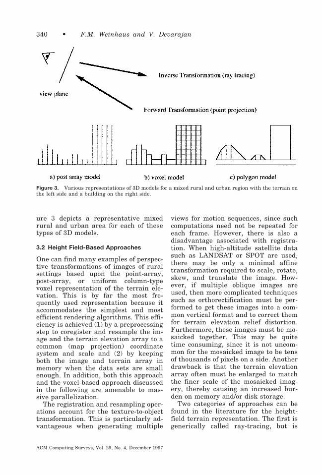
ure 3 depicts a representative mixedrural and urban area for each of thesetypes of 3D models.
3.2 Height Field-Based Approaches
One can find many examples of perspec-tive transformations of images of ruralsettings based upon the point-array,post-array, or uniform column-typevoxel representation of the terrain ele-vation. This is by far the most fre-quently used representation because itaccommodates the simplest and mostefficient rendering algorithms. This effi-ciency is achieved (1) by a preprocessingstep to coregister and resample the im-age and the terrain elevation array to acommon (map projection) coordinatesystem and scale and (2) by keepingboth the image and terrain array inmemory when the data sets are smallenough. In addition, both this approachand the voxel-based approach discussedin the following are amenable to mas-sive parallelization.
The registration and resampling oper-ations account for the texture-to-objecttransformation. This is particularly ad-vantageous when generating multiple
views for motion sequences, since suchcomputations need not be repeated foreach frame. However, there is also adisadvantage associated with registra-tion. When high-altitude satellite datasuch as LANDSAT or SPOT are used,there may be only a minimal affinetransformation required to scale, rotate,skew, and translate the image. How-ever, if multiple oblique images areused, then more complicated techniquessuch as orthorectification must be per-formed to get these images into a com-mon vertical format and to correct themfor terrain elevation relief distortion.Furthermore, these images must be mo-saicked together. This may be quitetime consuming, since it is not uncom-mon for the mosaicked image to be tensof thousands of pixels on a side. Anotherdrawback is that the terrain elevationarray often must be enlarged to matchthe finer scale of the mosaicked imag-ery, thereby causing an increased bur-den on memory and/or disk storage.
Two categories of approaches can befound in the literature for the height-field terrain representation. The first isgenerically called ray-tracing, but is
Figure 3. Various representations of 3D models for a mixed rural and urban region with the terrain onthe left side and a building on the right side.
340 • F.M. Weinhaus and V. Devarajan
ACM Computing Surveys, Vol. 29, No. 4, December 1997

usually only ray-casting, because sec-ondary rays for reflection and/or refrac-tion are not generally spawned. This isan inverse (screen-to-object) transfor-mation approach. The second is whatmight be called point projection, whichis a forward (object-to-screen) transfor-mation approach. These two approachesare depicted in Figure 3.
3.2.1 Ray-Tracing Approaches forHeight Fields. With the ray-tracingapproach, every pixel in the screen (out-put view) is processed in sequence. Thismight be described as output datadriven and it grows in proportion to thesize of the screen image generated andto a lesser extent in proportion to thesize and complexity of the 3D terrainmodel. A ray from the (output) eye pointis cast through each screen pixel in se-quence and its intersection with the ter-rain is determined. Dungan’s [1979]shaded terrain work, described earlier,used a ray-tracing technique. Butlerand Harville-Hendrix [1988] and Butler[1989] at Visual Information Technolo-
gies (VITec, now Connectware Inc.), andNack et al. [1989a, b] at Image DataCorp. (now called Core Software Tech-nology) have independently presentedray-tracing examples of image perspec-tive transformations using variations onan extremely efficient algorithm calledaccelerated ray-tracing (ARTS) [Fuji-moto et al. 1986]. This technique uses a3D DDA concept, which steps along theprojection of the ray on the groundplane in horizontal units equivalent tothe terrain post spacing, decrements theelevation of the ray by a constantamount precomputed from the slope ofthe ray, and compares it with the corre-sponding elevation of the terrain. Whenthe ray height makes the transitionfrom above the terrain elevation to be-low the terrain elevation, the ray haspierced the terrain. See Figure 4. Thena nearest-neighbor or higher-order in-terpolation, such as bilinear, cubic con-volution, or windowed sinc function, canbe used to compute the (X, Y) groundcoordinates of the intersection. Once
Figure 4. Ray-tracing methodology.
Texture Mapping 3D Models • 341
ACM Computing Surveys, Vol. 29, No. 4, December 1997

these coordinates are determined, thecorresponding location in the textureimage is addressed and the color of thispixel or interpolated color from neigh-boring pixels is transferred to thescreen. In certain circumstances, speed-ups can be achieved for each subsequentpixel along a screen column by startingthe search each time from the last inter-section rather than from the (X, Y) co-ordinate of the eye point.
When higher order interpolation isused to locate the exact terrain intersec-tion, the terrain is essentially repre-sented by a smooth surface rather thanby a step-function. Therefore, this inter-polation anti-aliases ridgelines; that is,it smooths out these “jaggies.” Further-more, when higher-order interpolationis used to resample the input image,some texture anti-aliasing can beachieved (by virtue of the larger inter-polating kernel size) to mitigate the ar-tifacts produced by undersampling. Thisanti-aliasing reduces the amount ofspeckling in single scenes and blinkingor shimmering in motion sequences thatare typical of ray-traced oblique per-spective views. However, due to the fi-nite size of the interpolating kernel, themitigating effects are of limited benefit.In fact, they fail where there is a largechange in scale between the input andoutput images, for example, in the back-ground regions of a low oblique perspec-tive view. In such cases, an output pixelwould have a very elongated “footprint”if projected into the input image, cover-ing many or even hundreds of pixels.Thus, a bilinear, cubic convolution, orwindowed sinc function kernel (nomi-nally, 2 3 2, 3 3 3, and 7 3 7 pixels on aside, resp.) would not adequately sam-ple the data within this “footprint.”
The height-field approach also hasbeen applied to the urban setting wherethe elevations of the terrain posts areraised locally to account for the heightsof buildings. However, the faces ofbuildings rendered in this manner oftendisplay a vertically striped appearance,since the texture values along theboundaries of the roofs are simply ex-
tended down the sides of the buildingswhere no source texture is available. Inother words, this approach simply as-signs the texture that corresponds tothe top of the elevation posts to thesides of the (visible) posts.
The approach used by the Jet Propul-sion Laboratory to make their earlymovies was also a ray-tracing method.It has been described by Hussey et al.[1986] and Mortensen et al. [1988]. Sub-sequently, Stanfill [1991] has intro-duced multiresolution (pyramid) imag-ery techniques into JPL’s approach toreduce the sparkling artifact typical ofaliasing. A precomputed lookup tablebased upon the range from the eye pointto the terrain is used to select the ap-propriate image resolution level to useduring rendering. Each output pixel isthen rendered as a weighted blend fromtwo different input image resolutionlevels so that no sudden spatial or tem-poral transitions in resolution are ap-parent. Figure 5 is an example imagegenerated by this multiresolution ray-casting technique using a height-fieldrepresentation for the terrain.
Such pyramid techniques are muchbetter at mitigating the aliasing arti-facts previously discussed because theinput data are more completely repre-sented in any sampling for an outputpixel. The downside is that they tend toovercompensate; that is, they includetoo many input data in their “footprint”sampling, since they are usually gener-ated with a square rather than a rectan-gular averaging filter. Often the resultis too much blurring rather than toomuch aliasing. See Williams [1983] andHeckbert [1989, 1983] for more details.
Devich and Weinhaus [1981b] alsopresented a novel variation on the ray-tracing concept. They recognized that,for a camera with a horizontally ori-ented optical axis, columns and rows onthe screen correspond to azimuth andelevation angles. Therefore, before ray-tracing, they processed both the terrainelevation array and the image into apolar coordinate system centered at the(X, Y) position of the eye point. They
342 • F.M. Weinhaus and V. Devarajan
ACM Computing Surveys, Vol. 29, No. 4, December 1997

also processed the elevation values inthe terrain array, first to correct forearth curvature and then into valuesrepresenting screen-line coordinateswhich are proportional to the tangent ofthe elevation angles. Ray-tracing wasthereby transformed from incrementingboth X and Y ground coordinates toincrementing simply radial distance,that is, along a single dimension. Fur-thermore, no decrement in the ray ele-vation was required, because of the con-version of the terrain elevation valuesto a quantity more related to elevationangle. Thus, extra computations associ-ated with the Cartesian-to-polar and el-evation-to-elevation-angle processingwere traded for more efficient ray-trac-
ing. Weinhaus and Walterman [1990]have pointed out that the Cartesian-to-polar transformation need only be setup once in the form of a spatial transfor-mation lookup table and can be used forall subsequent translations of the eyepoint (but not for changes in view direc-tion). For the case of tilted views, Dev-ich and Weinhaus implemented an ex-tra one-dimensional transformationalong each row of the screen space im-age to correct the geometry from that ofa horizontal view. Anti-aliasing wasachieved by processing multiple resolu-tion versions of the input into rangeannuli in the output and by using high-er-order resampling techniques. Ridge-lines were specially anti-aliased by
Figure 5. Computer-generated view of the 5 mi high volcano, Maat Mons, on Venus. Source dataincluded colorized radar imagery acquired by the Magellan spacecraft and altimeter elevation data inheight-field format. Perspective view generated by JPL/NASA and photo obtained from Newell ColorLab.
Texture Mapping 3D Models • 343
ACM Computing Surveys, Vol. 29, No. 4, December 1997
blending information from foregroundand background pixels using area cover-age weighting factors.
Paglieroni and Peterson [1992] havepresented a ray-tracing method thatadaptively optimizes each step size dur-ing the ARTS algorithm. Their methodinvolves preprocessing the elevationdata using distance transforms [Borge-fors 1986; Paglieroni 1992]. For eachpossible height value in the digital ele-vation array, they extract a horizontalcross-sectional slice in the form of abinary image. This binary image codesregions above and regions equal to orbelow the given elevation value. TheX–Y Euclidean distance from each“above” pixel to the closest “equal to orbelow” pixel in a plane is then computedand stored. In concept, this would forma set of hierarchical distance, images,one image for each possible height valuewithin the data. During ray-tracing, the(X, Y, Z) position at a given step couldbe used to look up the next step’s hori-zontal increment from within the set ofhierarchical distance images. However,to save on disk storage, for each pixel inthe elevation model, they form a para-metric representation for the hierarchi-cal data. This approximation sets alower bound on the step size. Thus, inplace of the full sequence of distances asa function of height values, only a slopeand intercept are stored for each pixelin the digital elevation array. The dis-tance to use for any given step is thencomputed from these slope and inter-cept values rather than from an actuallookup into the hierarchical distanceimages. For the data tested, Paglieroniand Peterson found speedup factors fortheir algorithm of about 40 and 6 whencompared to a uniform step, acceleratedray-tracing method, and to an hierarchi-cal step, octree-like ray-tracing method,respectively.
3.2.2 Point Projection Approaches forHeight Fields. In the point projectionapproach, the registered image and ter-rain elevation array are divided intocorresponding profiles and these dual
profiles are processed one pair at a timeas follows. First, each pixel in the ter-rain elevation profile is projected fromobject space to screen space where it isusually truncated or rounded to theclosest integer coordinate. Then the tex-ture value from the corresponding pixelin the image profile is assigned to thespecified screen coordinate. This processis input data driven and grows in pro-portion to the size of the registered 3Dterrain model and source (texture) im-age.
One generally finds two commonforms of hidden pixel removal used inconjunction with the point projectionapproach: the painter’s algorithm andthe floating horizon algorithm. How-ever, in either case, the profiles typi-cally are linear slices through the regis-tered digital elevation array and textureimage oriented orthogonal to the projec-tion of the output view’s optical axisonto these data sets. Alternately, theymay simply be rows or columns of thisdual data, if properly sequenced. Figure6 depicts both kinds of point projectionalgorithms as discussed in the follow-ing.
In the painter’s algorithm, the pro-files are processed starting with themost distant profile from the eye pointand advance towards the profile closestto the eye point. When textures corre-sponding to different terrain elevationprofiles contend for the same screenpixel, the current one (associated withthe closest profile to the eye point) al-ways overwrites the previous one.
In the floating horizon technique, theprofiles are processed in the oppositeorder; that is, they advance from theprofile closest to the eye point towardsthe profile furthest from the eye point.A floating horizon buffer is maintainedas a mechanism to eliminate hiddenpixels. As each profile is processed, thisbuffer is potentially updated and savesthe screen line coordinate associatedwith the current horizon for each screensample coordinate. Any projected pointthat falls below the current horizon isignored. The current horizon is only up-
344 • F.M. Weinhaus and V. Devarajan
ACM Computing Surveys, Vol. 29, No. 4, December 1997

dated whenever a projected point fallsabove the current horizon. When tex-ture pixels corresponding to differentterrain elevation profiles contend forthe same screen pixel on this horizon,the current one is usually ignored infavor of the previous one (associatedwith the closer profile to the eye point).Alternately, an area weighted averaging
(A-buffer) technique may be used foreach horizon screen pixel to store andblend values from texture pixels associ-ated with more than one profile.
A disadvantage common to the pointprojection technique occurs when trans-forming terrain elevation and texturearrays for close-range viewing. In thiscase, without special techniques such as
Figure 6. Point projection approaches. (a) Terrain image: brightness encoded elevation. Higherelevations are darker; (b) perspective view (every 8th row): profiles processed back to front for Painter’salgorithm; profiles processed front to back for Floating Horizon algorithm; (c) Painter’s algorithm:partially processed; (d) Floating Horizon algorithm: partially processed showing current location offloating horizon.
Texture Mapping 3D Models • 345
ACM Computing Surveys, Vol. 29, No. 4, December 1997

described by Fant [1986], undersam-pling in screen space will leave unfilledpixels. For nearly horizontal and low-altitude viewing conditions, this oftenoccurs in the foreground part of theoutput image where the source data aremagnified. The opposite situation oroversampling in screen space is a com-mon occurrence in the background partof the output image or for overall dis-tant viewing where source data areminified. In this case, many texture pix-els are transformed to the same screenlocation. This is definitely inefficientunless multiresolution source imagerytechniques are used. One advantagetypical of the point projection techniqueis that ridgeline anti-aliasing is easilyachieved with the floating horizon ap-proach when it uses an A-buffer.
Tanaka’s [1979] example describedearlier used the painter’s method.Junkin [1982] at NASA also has pre-sented examples of point projections ofLANDSAT images in perspective, buthe used the floating horizon method.Other examples of the point projectionmethod have been presented by Fish-man and Schachter [1980] at GeneralElectric and Smedley et al. [1989] atLockheed. However, their examplestransformed synthetic images generatedby a terrain elevation diffuse shadingalgorithm. Smedley’s examples usedbathymetric elevation data. Bernsteinet al. [1984] and Pareschi and Bernstein[1989] at IBM presented transforma-tions of images of the San Francisco Bayarea and of Mt. Etna, respectively, butprojected them, orthographically ratherthan perspectively. Carlotto and Hartt[1989] at TASC presented orthographicprojections of images of Mars using avariation on the floating horizon tech-nique that they implemented in theform of a preprocessing step to identifyhidden pixels. They obtained their ele-vation data using a shape-from-shadingtechnique.
A novel orthographic point projectionapproach also based upon horizon infor-mation has been developed by Dubayahand Dozier [1986] at the University of
California Santa Barbara. In this tech-nique, the terrain elevation grid is pre-processed to compute an array whoseintensity at each element represents theangle to the local horizon. During pointprojection, the elevation angle for agiven terrain point is tested against thispreprocessed horizon angle to determinewhether it is visible. These authors alsodeveloped an accumulation technique toaddress the problem of unfilled screenpixels. Each registered terrain elevationand texture pixel is projected to thescreen, but the coordinates are kept tofloating point precision rather than sim-ply truncated or rounded to the inte-gers. Then a fraction of the color isassigned to each of the four closestscreen pixels according to an inversedistance weighting scheme. Each screenpixel can accumulate fractional colorfrom more than one texture pixel. Fi-nally, the accumulated color at a screenpixel is normalized by the sum of theinverse distances accumulated for allthe texture pixels that contributed to it.
Another point projection approachthat mitigates hole-like artifacts hasbeen presented by Petersen et al. [1990]at Brigham Young University. In theirback-to-front approach, the complete el-evation post is rendered to the screen byprojecting both its top and bottom andsubsequently connecting a line betweenthe two points. Then each screen pixelalong the line is assigned the color ofthe source texture pixel that corre-sponds to the elevation post.
A novel variation similar in concept tothe 1D approach of Devich and Wein-haus has been developed by Robertson[1987] at CSIRO, but is based upon thepoint projection approach. Robertsonused a combination of rotational andrhombic deformations of the texture im-age and terrain elevation array, ratherthan the Cartesian-to-polar one, totransform to a domain where the projec-tion became one-dimensional (i.e., alongrows or columns in the transformed do-main). However, he used a back-to-frontprojection technique rather than a ray-tracing method to render the output.
346 • F.M. Weinhaus and V. Devarajan
ACM Computing Surveys, Vol. 29, No. 4, December 1997

3.3 Octree/Voxel-Based Approaches
Perspective transformations of imagesusing octree encoded voxels also havebeen used. One finds both forward pro-jections from the voxels to the screenand inverse projections from the screento the voxels. The forward transforma-tion technique is similar to the pointprojection technique previously de-scribed, except all nodes of the octreeare projected at their appropriate levelsof detail. Indexing and projection of thenodes of the octree may progress eitherfrom the back towards the front or fromthe front towards the back. The inversetransformation technique uses the ray-tracing concept, but must intersect andidentify the appropriate node of the oc-tree.
Not only does the voxel carry the 3Dstructure, but it also can be coded withsource image color or other attributesabout the model that would be usefulfor simulating views by such nonvisualsensors as infrared and radar. Further-more, when multiresolution source im-agery is used, a color can be assigned toeach node of the structure using thepixel color at the corresponding imageresolution level. The octree hierarchyallows the voxel approach to deal withvertical faces of urban 3D objects inaddition to the surface of the terrain.However, unless very fine voxels areused, this technique will not representsloped surfaces of urban models verysmoothly.
Nack et al. [1989a, b] used a software-based ray-tracing approach and havepresented perspective transformationsshowing the sides of individual build-ings at high resolution as well as thoseof rural settings. Figure 7 is an exampleimage generated by this type of ray-tracing approach using a column voxelrepresentation for the terrain. On theother hand, Scuderi and Strome [1988]have presented voxel projection trans-formations of both rural and urban set-tings. These output images were gener-ated on prototype hardware developedby Hughes Aircraft Co. However, their
results for the urban environment alsodisplayed the same striping artifacts onthe sides of the buildings as was de-scribed earlier, due to the use of simplecolumn voxels and vertical photography.
3.4 Polygon/Patch-Based Approaches
The traditional polygon and patch rep-resentation of 3D models has also beenused to perform perspective transforma-tions of images. In this case, the follow-ing techniques similar to those used forordinary texture mapping can be ap-plied: back-to-front or front-to-backdepth-priority, depth-buffer, scan-line,polygon subdivision, and ray-tracing.
An example of an early polygon-basedapproach was Sun Microsystem’sMAPVU demo [1989] which ran on theirTAAC-1 accelerator. It processed a reg-ular 3D mesh of triangles in a back-to-front (painter’s) fashion. Each vertex ofa triangle was assigned the color of thecorresponding pixel in the image tex-ture. Triangle vertices were projected tothe screen and the color for each screenpixel within a projected polygon wasinterpolated using the traditional colormethod. A quality parameter controlledsubsampling of the data. It permittedcoarse 3D mesh and texture data to beused thereby increasing the renderingrates for rapid previews. However, thisoccurred at the expense of poorer tex-tural detail, since no other source imagedata were used to fill the triangles.
Subsequent polygon-based ap-proaches such as those of SGI and Star-dent (now Kubota Graphics) could fillthe interior of each triangle in a coarsemesh with high resolution texture fromthe source image. The approach takenin this case properly interpolated thetexture coordinates for each projectedtriangular polygon from texture coordi-nates stored at the vertices. Then theinterpolated texture coordinates wereused to look up the color in the sourceimage. A depth-buffer was used to re-move hidden pixels.
In many high resolution, nonreal-timepolygon-based terrain rendering appli-
Texture Mapping 3D Models • 347
ACM Computing Surveys, Vol. 29, No. 4, December 1997

cations, the grid of elevation values ispreprocessed to resample it to the sameresolution as the (rectified) image. Thisis advantageous in the following ways.First, it means that texture coordinateinterpolation is unnecessary, sincethere are no interior texture pixels toaccess. It suffices in this case simply toassign the colors of the image pixels totheir corresponding mesh vertices andinterpolate them across the polygon usingthe traditional color method. Second, ifhigher-order interpolation techniquesare used in the terrain resampling pro-cess, then the terrain will display asmoother appearance, although nottruly any more accurate than in its orig-inal representation. Other advantagesassociated with resampling the texture
data and 3D model geometry to a com-mon coordinate system have been dis-cussed by Cook et al. [1987]. The maindisadvantage is that the complexity(i.e., number of polygons in the terrain3D model) rises dramatically. Thus,rendering can become extremely timeconsuming for large, high resolutiondata sets. Techniques that generate anduse multiresolution terrain elevationdata are therefore necessary to mitigatethis problem.
Moreover, when the data sets are toolarge to be totally contained in memory,tiling (i.e., partitioning the data intoblocks) also becomes important. For ex-ample, Blinn [1990] has explained tilingand paging strategies that he has usedto perform efficient texture mapping of
Figure 7. Perspective view of the area, around Pasadena, CA, computer-generated from coregistered30 m LANDSAT Thematic Mapper imagery and voxel format terrain elevation data. Courtesy of ImageData Corp. (now Core Software Technology ©).
348 • F.M. Weinhaus and V. Devarajan
ACM Computing Surveys, Vol. 29, No. 4, December 1997

astronomical photographs of the planetsonto spherical models.
Gelberg et al. [1988] and Hughes[1991] each used combined tiled andmultiresolution (pyramid) approaches togenerate TASC’s Calgary video and Ap-ple’s Mars Navigator videos, respec-tively. Each started with a terrain ele-vation grid that was registered to a verylarge rectified image (36 million pixelsin Gelberg’s example and 145 millionpixels in Hughes’ example). Gelbergused a simple tiled pyramid approachand Hughes used the MIP map pyramidapproach.
In a simple tiled pyramid approach[Tanimoto and Pavlidis 1975; Burt1981], multiple versions of the sourceterrain elevation grid and/or imageryare created usually with a factor of twosteps in resolution, stopping at a speci-fied block size. Each version is thensubdivided into blocks, reformatted inscan-line order and stored as a hierar-chy of tiles, each containing one block ofdata. In the MIP map approach [Wil-liams 1983], the source terrain eleva-tion grid and/or imagery are first di-vided into blocks. A pyramid is thenformed for each block, typically stoppingwhen the size is 2 3 2 pixels. Finally allresolution versions of a given block arereformatted in scan-line order andstored successively in the same tile. Inthe simple tiled pyramid, the number ofresolution levels is given by (1 1 log2(original image size/block size)). In theMIP map pyramid, the number of reso-lution levels is given by (1 1 log2 (blocksize/2)).
An advantage of the MIP map ap-proach over the simple tiled pyramidapproach is that all resolutions of thedata are always readily available forany MIP map tile in memory. This isespecially convenient when it is desiredto blend data from two successive reso-lutions so that sudden transitions inresolution are not detected. When usedin conjunction with bilinear resampling,this technique is commonly referred toas trilinear interpolation. On the otherhand, a disadvantage is that memory is
less efficiently allocated with the MIPmap approach. This occurs because thehigher resolution data also must be car-ried along for those MIP-mapped tilescorresponding to the background areasof the output scenes where only lowresolution data are needed. When mem-ory is limited, more tile paging is re-quired due to the smaller amount of lowresolution data available in any one tile.A compromise approach might be tostore a sequence of MIP maps for eachblock of the image where each MIP mapcontains only two successive resolu-tions. However, this would increase thetotal data load from a factor of 4/3 timesthe original image and/or terrain eleva-tion array size to 5/3 times the originalimage and/or terrain elevation arraysize.
In Hughes’ approach, only those ter-rain elevation tiles that were found tolie at least partially within the outputimage’s ground “footprint” (projectiononto the X, Y ground plane) were ren-dered. The terrain elevation model andimagery resolutions were selected as afunction of distance between the terrainelevation tile and the eye point so thatcoarse resolution could be used for moredistant regions. Terrain elevation tileswere then tessellated into triangularmeshes at the specified resolution. Thencolor values from the corresponding res-olution imagery pixels were assigned toeach triangle vertex. An SGI computerwas used to perform the rendering bysimply interpolating the color valuesacross the triangles and by using adepth-buffer to remove hidden pixels.
In Gelberg’s approach, terrain eleva-tion tiles were processed by orderingthem according to distance in a back-to-front manner after eliminating thosetiles that were not at least partiallywithin the viewing frustum of the out-put image. The appropriate resolutiondata were determined from the ratio ofthe number of quadrilateral polygons tothe number of screen pixels. A Pixarcomputer was used to perform the ren-dering using the ChapReyes software[Cook et al. 1987]. This software subdi-
Texture Mapping 3D Models • 349
ACM Computing Surveys, Vol. 29, No. 4, December 1997
vides each 3D model primitive intoquadrilateral-shaped planar micropoly-gons and renders them using a depth-buffer to remove hidden pixels.
Kaneda et al. [1989] in Japan alsogenerated perspective transformationsof rural settings using a quadrilateralmesh to represent the 3D model of theterrain. Their algorithm used a back-to-front depth-priority technique for ren-dering. However, they used a speciallypreprocessed, radially organized quadri-lateral mesh rather than one in a recti-linear format. This was done to gener-ate uniformly sized quadrilaterals inscreen space. Fewer quadrilaterals areneeded this way, since they are corre-spondingly larger in object space asthey progress farther into the distance.These authors also created multiple res-olution versions of the vertically ori-ented (aerial) image and selected theappropriate resolution to use for eachquadrilateral so that high resolutiontexture was not wasted for the back-ground regions of the scene.
Another quadrilateral-based approachhas been presented by Whiteside et al.[1987] and Whiteside [1989] at DBA,but it used a combination of depth-buffer and accumulation-buffer tech-niques for rendering. In this implemen-tation, more than one source image wasused to render the area of interest, butthey were first orthorectified and mosa-icked to a vertical format. Multiple res-olution versions of the mosaicked imagewere created subsequently and used asrequired to avoid oversampling of theinput texture. This was achieved by pro-jecting each 2 3 2 set of terrain eleva-tion posts into input (texture) space andscreen space and selecting the textureresolution that nearly matched thequadrilateral areas in the two domains.Then a forward projecting, bilineartransformation rather than a true per-spective transformation was used tomap the rectangular-bounded input tex-ture areas to quadrilateral-boundedoutput screen areas. Screen-space anti-aliasing was nicely achieved for theoversampling case using an accumula-
tion buffer. (No discussion of the under-sampling case was presented. However,the resampling scheme described byFant [1986] should be applicable to theapproach advocated by these authorsand would mitigate this problem.)These authors also were able to render3D cultural features with rectangularfaces, such as buildings. The texturesfor these faces, however, had to becropped from the images and geometri-cally preprocessed into face-on views be-fore they could be used.
In general, quadrilaterals are espe-cially difficult 3D primitives to use, be-cause they are not necessarily planar.Even when their edges are constrainedso that they form bilinear surfaces, theymay still present ridgelines for a partic-ular view. Thus, back-facing portions ofthe surfaces must be taken into accountif they are to be handled rigorously.Generally, triangles (and planar quadri-laterals) are much easier to deal with,because testing for backfacing condi-tions need only be done once per surfacerather than at every interior pixel. Ithas therefore been necessary whendealing with nonplanar quadrilateralsto use approximations and other specialtechniques, such as polygon subdivision,in order to avoid these difficulties.
3.5 Approach Comparison
Table 3 presents a comparison of thevarious categories of approaches thathave been discussed. The approacheshave been categorized as mentionedearlier by the geometry primitives andrendering methods used. The compari-son identifies the major advantages anddisadvantages of each category. Toomany algorithmic variations within cat-egories have been presented to go intodetails for each. The advantages anddisadvantages that have been presentedhere focus on issues such as resultingquality (e.g., aliasing), processing effi-ciency, and the ability to handle urban(man-made) as well as rural (naturalterrain) features.
350 • F.M. Weinhaus and V. Devarajan
ACM Computing Surveys, Vol. 29, No. 4, December 1997
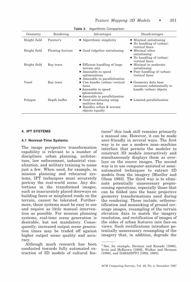
4. IPT SYSTEMS
4.1 Nonreal-Time Systems
The image perspective transformationcapability is relevant to a number ofdisciplines: urban planning, architec-ture, law enforcement, industrial visu-alization, and military training to namejust a few. When used, for example, inmission planning and rehearsal sys-tems, IPT techniques must accuratelyportray the real-world scene. Any dis-tortions in the transformed images,such as inaccurately placed doorways onbuilding faces or misplaced roads on theterrain, cannot be tolerated. Further-more, these systems must be easy to useand require as little manual interven-tion as possible. For mission planningsystems, real-time scene generation isdesirable, but not mandatory. Conse-quently, increased output scene genera-tion times may be traded off againsthigher output scene quality and accu-racy.
Although much research has beenconducted towards fully automated ex-traction of 3D models of cultural fea-
tures2 this task still remains primarilya manual one. However, it can be madeuser-friendly in several ways. The firstway is to use a modern man–machineinterface that permits the modeler toconstruct 3D models interactively andsimultaneously displays them as over-lays on the source images. The secondway is to use computer-assisted or semi-automated techniques to extract 3Dmodels from the imagery [Mueller andOlson 1993]. The third way is to elimi-nate potentially unnecessary prepro-cessing operations, especially those thatcan be folded into the basic projectivegeometry transformations used duringthe rendering. These include: orthorec-tification and mosaicking of ground cov-erage images, resampling of the terrainelevation data to match the imageryresolution, and rectification of images ofthe sides of urban features into face-onviews. Such rectifications introduce po-tentially unnecessary resampling of theimagery that, in addition, degrade the
2 See, for example, Herman and Kanade [1986],Irvin and McKeown [1989], Walker and Herman[1988], and DARASISTO [1992, 1993].
Table 3. Algorithmic Comparison
Geometry Rendering Advantages Disadvantages
Height field Painter’s ● Algorithmic simplicity ● Minimal antialiasing● No handling of (urban)
vertical facesHeight field Floating horizon ● Good ridgeline antialiasing ● Minimal other
antialiasing● No handling of (urban)
vertical facesHeight field Ray trace ● Efficient handling of large
terrain sets● Minimal to moderate
antialiasing● Amenable to speed
optimizations● Poor handling of (urban)
vertical faces● Amenable to parallelization
Voxel Ray trace ● Can handle (urban) verticalfaces
● Geometry data baseincreases substantially to
● Amenable to speedoptimizations
handle (urban) objects
● Amenable to parallelizationPolygon Depth buffer ● Good antialiasing using
multires data● Limited parallelization
● Handles urban & terrainobjects equally
Texture Mapping 3D Models • 351
ACM Computing Surveys, Vol. 29, No. 4, December 1997

results. Several nonreal-time, worksta-tion-based systems have made advancesin these areas. These include systemsdeveloped by TRW/ESL, General Dy-namics Electronics Corp., SRI, and theUniversity of California at Berkeley.
TRW’s system renders the outputscenes by computing texture coordi-nates for every screen pixel using anincremental scan-line method to evalu-ate the fractional linear perspectivetransformation of Equation (1). Thistransformation is able to account for theoblique geometry of the source textureimages as well as the viewing perspec-tive associated with the output. The ar-ticles by Devich and Weinhaus [1980,1981a] and Weinhaus and Devich [1997]showed how to derive the fractional lin-ear transformation coefficients for a pla-nar polygon independent of the numberof its vertices without the need to storeu, v (or w) texture coordinates for eachpolygon. The only information needed isthe camera parameter model for thetexture image and the equation of theplane for the polygon. In fact, the fourcoefficients defining the plane need notbe carried with the polygon, since theycan be generated from the world coordi-nates of the vertices.
In this system, none of the imagery,either for the texture for the groundcovering or for the sides of urban fea-tures, has to be rectified or mosaicked.A simple tiled pyramid is created foreach source image and the appropriatetile (or tiles) is automatically selected tocover each surface at an appropriateresolution for anti-aliasing. A deferredtexturing, depth-buffer technique isused and various resampling techniquesmay be selected to trade quality versusspeed, including supersampling and/orEWA on a pyramid. The EWA technique[Greene and Heckbert 1986] is a verygood method for anti-aliasing, since itsamples the input data within an ellip-tical “footprint” region that representsthe projection of a given (circular) out-put pixel. The size and orientation ofthe ellipse adapts to the geometry anddepends upon the orientation and loca-
tion of both the input and output cam-eras and the orientation of the 3Dmodel surface upon which it is pro-jected.
The terrain elevation data, whichoriginate from a regular grid of eleva-tion values, are automatically reformat-ted into a multiresolution triangularsurface mesh for each output frame.This allows coarser triangles to be usedin the background of output images andfiner ones to be used in the foreground.However, before rendering any frame,surfaces from two levels are blended.This prevents sudden transitions inlevel of detail from being observed inmotion sequences. Urban features aremodeled by interactively adjusting“elastic” wireframe models on one ormore source images simultaneously.Figures 8 and 9 show examples of animage perspective transformation for anurban and rural area, respectively pro-duced by this system using the polygonrepresentation for the terrain elevationmodel and the cultural objects.
The SOCET SET system, built byGeneral Dynamics Electronics Corp.[Inman and McMillan 1990] uses stereoimage pairs as the source of its 3D infor-mation. A combination of automatic ste-reo compilation followed by manual ed-iting can be used to generate the terrainelevation model. The construction of 3Dcultural models is performed interac-tively on this system using a stereo-scopic monitor for visualization orby using semi-automated techniques[Mueller and Olson 1993]. For example,the vertices of the top of a rectangularparallelepided-shaped building can beidentified manually with a “floating”cursor. Then a wire-frame graphic isdraped automatically about the bound-ary of the building with the bottom por-tion “buried” below the ground.
The Cartographic Modeling Environ-ment [Hanson et al. 1987; Hanson andQuam 1988], developed by Hanson andQuam at SRI, was created to supportresearch on interactive, semi-automatic,and automatic computer-based carto-graphic activities. This system uses
352 • F.M. Weinhaus and V. Devarajan
ACM Computing Surveys, Vol. 29, No. 4, December 1997
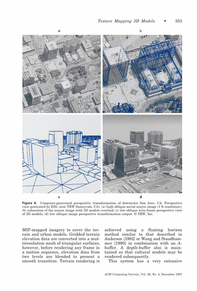
MIP-mapped imagery to cover the ter-rain and urban models. Gridded terrainelevation data are converted into a mul-tiresolution mesh of triangular surfaces;however, before rendering any frame ina motion sequence, elevation data fromtwo levels are blended to present asmooth transition. Terrain rendering is
achieved using a floating horizonmethod similar to that described inAnderson [1982] or Wang and Staudham-mer [1990] in combination with an A-buffer. A depth-buffer also is main-tained so that cultural models may berendered subsequently.
This system has a very extensive
Figure 8. Computer-generated perspective transformation of downtown San Jose, CA. Perspectiveview generated by ESL (now TRW Sunnyvale, CA). (a) high oblique aerial source image (1 ft resolution);(b) subsection of the source image with 3D models overlaid; (c) low oblique wire-frame perspective viewof 3D models; (d) low oblique image perspective transformation output. © TRW, Inc.
Texture Mapping 3D Models • 353
ACM Computing Surveys, Vol. 29, No. 4, December 1997

Figure 9. High and low oblique, computer-generated perspective views of the area around Irish Canyon,CO. Source data were composed of 20 m SPOT imagery and polygonalized 10 m terrain elevation data thatwere vertically exaggerated by a factor of 5. Source data courtesy of STX Corp. Perspective viewsgenerated by ESL (now TRW Sunnyvale, CA).R TRW, Inc.
354 • F.M. Weinhaus and V. Devarajan
ACM Computing Surveys, Vol. 29, No. 4, December 1997

menu of interactive modeling and ma-nipulation tools. For example, wire-frame models may be rotated aboutworld axes, about any object edge, orabout a line from an object vertex to thesun’s position. It may even be movedalong the ray from the eye point to theobject. Shadow mensuration is an op-tion that can be used to help in 3Dmodel construction. Also, shadows canbe rendered into a graphic overlay onthe transformed view. Semi-automated2D feature extraction tools, such as roadfollowing and the detection of bound-aries of buildings whereby the userstarts the extraction process with amanual cue, also are included. SRI alsohas experimented with automatic ex-traction of 3D models of buildings andused their system to portray the results[Fua and Hanson 1989].
The University of California at Berke-ley’s Facade System developed by De-bevec et al. [1996] was designed tomodel and render architectural scenesfrom multiple photographic inputs. Itsobjective is to create high quality out-puts of a small number of detailed ar-chitectural structures rather than largeareas of rural and/or urban content. Inthis system, 3D models composed ofparametric primitives such as blocks,pyramids, and the like are manuallycomposited to approximate the geome-try of the architectural structure usingthe imagery as a visual guide. The focusis on linking the right shapes togetherwithout putting significant effort intosetting the exact size and orientation.Then a few corresponding edges are lo-cated in the source imagery and on the3D models. A nonlinear least square fitis then performed to recover simulta-neously the parameters (size, orienta-tion, etc.) of the primitives in the 3Darchitectural model as well as the cam-era location and orientation parametersfor each of the source images.
A novel view-dependent texture-map-ping technique is used to render thearchitectural model. Multiple photo-graphs are projected onto the model inorder to texture its surface completely.
(An image-space shadow-mapping algo-rithm based on a z-buffer is used tokeep track of obscurations.) However,since the photographs overlap, the ren-dering algorithm must decide whichphotograph or photographs to use ateach output pixel. Here, a weighted av-erage of the textures from the overlap-ping images is used, where the weightsare the angular deviations of the view-ing vectors of each source image fromthat of the output view. Moreover, toavoid visible “seams,” the weights areramped near the boundaries of sourcephotographs. Optionally, a model-basedstereo correlation algorithm may beused to refine the 3D model to includefiner detail such as recessed windows,and the like, and to increase the fidelityof the texture-mapped rendering. Toachieve this result, the base 3D model isfirst used to create an output view sim-ilar to the orientation of one of theexisting source images. These two im-ages are then used as input to the auto-mated stereo correlation algorithm. Thestereo correlation produces a disparityimage that can be converted into adepth map which in turn is used as arefined z-buffer for re-rendering theoutput view.
4.2 Real-Time Systems
In contrast, the training industries andin particular the commercial and mili-tary flight and ground vehicle simula-tion industries have traditionally re-quired real-time scene generation ratesin their visual systems and, historically,have traded off quality and realism toachieve these rates. These visual sys-tems produce interactively controlledmoving images that depict on the simu-lator display what the pilot or drivermight see if he or she were looking“out-the-window” or at a monitor for asensor mounted on the vehicle. In theinterest of speed, both data and algo-rithms are trimmed to the bare-boneslevel for use by such systems. The de-velopment of this technology histori-cally took two different paths, direct
Texture Mapping 3D Models • 355
ACM Computing Surveys, Vol. 29, No. 4, December 1997

and hybrid. The direct approaches weresimply real-time implementations ofthe previously described polygon-based computer graphics techniques.The hybrid approaches merged com-puter graphics techniques with pre-stored digital images. However, bothapproaches ultimately converged onthe use of certain fundamental proce-dures, notably the use of digital or-thophoto mosaics and registered digi-tal terrain elevation data.
In the early 1980s, researchers atHoneywell [Scott 1983; Erickson et al.1984; Baldwin et al. 1983] developedone hybrid approach that they calledthe Computer Generated SynthesizedImagery (CGSI) technique. This ap-proach combined the best qualities atthe time of the Computer Graphics Im-agery (CGI) technique and the Com-puter Synthesized Imagery (CSI) tech-nique. The CGI technique, namely,coloring and illumination-based shadingof polygon models permitted full free-dom of motion through the gaming areaor database. However, it lacked realism.The CSI technique used high resolutiondigitized photographs as backgrounds,for example, for artillery training withcomputer-generated target models mov-ing around the scene. It attained a highdegree of realism, but basically was lim-ited to a single viewpoint, althoughsome motion could be simulated by pan-ning and zooming the background im-age. The CGSI technique combined thefull freedom of motion of the CGI tech-nique with the realism of the CSI tech-nique. This was achieved by using thecomputer graphics-generated imageryas the framework and inserting digi-tized photographs of real-world objects,such as buildings, trees, and targets atthe appropriate locations in the data-base. Multiple views of these objectswere photographed, digitized, and pre-stored on optical video disks. Duringreal-time image generation, when a par-ticular object was needed, the most ap-propriate view of it was retrieved andwarped to proper perspective accordingto Equation (1) for the specific output
image. Then it would be inserted intothe previously computed CGI back-ground with proper occlusions and bor-der blending. In effect, this combinationof image warping and insertion is equiv-alent to texture mapping the image ontoa planar 3D rectangle that has beenplaced in the database at the desiredlocation and orientation and subse-quently viewing it from the desired eyepoint.
Meanwhile, researchers at LTV Mis-siles and Electronics [Hooks and De-varajan 1981a] (now Lockheed-Martin-Vought Systems (LMVS)) developedanother type of hybrid approach thatthey called the “pseudo-film” approach.This monochrome image technique in-terpolated new output views at real-time rates from a small set of speciallycollected, oblique perspective photo-graphs. These photographs were ac-quired at locations corresponding to a3D matrix of eye points throughoutsome area of interest in the real world.Before real-time interpolation by theimage generator part of the system,these oblique perspective photographswere converted into large (typicallythousands of pixels on a side) electronicimages using a high resolution, digitalscanning process and then were storedon analog video disks. When the real-time simulation was started, the systemwould know at any given time what theaircraft position and attitude were. Itwould then retrieve the most appropri-ate oblique perspective image stored inthe video disk bank and then warp itaccording to Equation (1) to simulatethe pilot’s or sensor’s view of the gam-ing area at that instance in time. Sincethese operations were accomplished inreal-time, it would give the illusion ofsmooth interactive motion through thegaming area. An improved version ofthis system using color imagery and dis-plays as well as multiple output chan-nels has been described by Hooks andDevarajan [1981b] and by Mudunuriand Hooks [1985].
The warping operation used to inter-polate between successive oblique
356 • F.M. Weinhaus and V. Devarajan
ACM Computing Surveys, Vol. 29, No. 4, December 1997
source images in the LTV simulations(on their TOPSCENE Model 3500) con-sisted primarily of zooming, panning,and 2.5D perspective changes. Thezooming operation approximated for-ward motion, the panning operation ap-proximated lateral motion, and the 2.5Dperspective changes allowed smoothtransitions between successive input ob-lique images. Since the oblique inputimages were acquired in proper perspec-tive, they were constructed to have cor-rect elevation information built in forboth the terrain and urban features.Therefore, the process of warping thesource image according to Equation (1)to achieve limited changes in the per-spective of the output views was as-sumed to result in a good approximationof the true perspective view for thegiven output eye point. As the simula-tion proceeded through the gamingarea, the system would make the transi-tion at the appropriate time from usingone oblique source image to the next onein sequence. The warping process usedhere is again equivalent to texture map-ping the source image onto a single pla-nar 3D surface, in this case, the obliqueimaging plane of the source camera, butseen from a slightly different eye pointthan for that of the original image.
Eventually, the researchers at LTV[Devarajan and Chen 1986; Devarajan1989] generated the large oblique “pseudo-film” perspective images from mosaicsof overhead photographs rather than bycollecting actual oblique photography.Likewise, the researchers at Honeywell[Hopkins and Cooper 1988; Mudunuri1989] (now Hughes Training Inc.) even-tually replaced the background imagerygenerated by the CGI technique with asequence of computer-generated oblique“viewplane” images similar in nature toLTV’s computer-generated “pseudo-film” images. A sequence of these “view-plane” images typically was generatedto represent one or more “corridor” ap-proaches to a target area. The overheadsource images in both applications werefirst orthorectified to remove any ter-rain elevation relief distortion and then
mosaicked together to be in registrationwith the terrain elevation array. Theterrain elevation array was then refor-matted into a mesh of triangles. Itwould be used in this form along withthe registered orthophoto mosaic to gen-erate the requisite oblique “pseudo-film”or “viewplane” images for a desiredgaming area. The rendering techniquesused to create these oblique imageswere similar to those described in thepreceding sections for nonreal-time,polygon-based, perspective scene gener-ation. Since this rendering was per-formed by a nonreal-time preprocessingstep, there was no need to limit thenumber of polygons used to representthe terrain nor were there any restric-tions as to which anti-aliasing tech-niques could be used. Consequently,these oblique perspective images suf-fered no appreciable loss of quality orrealism.
In the late 1970s and early 1980s,another set of researchers, notably fromGeneral Electric and Evans & Suther-land, started developing direct tech-niques for real-time rendering of polyg-onal models of the terrain and urbanfeatures. These techniques were basedupon the tools evolving from the com-puter graphics industry. In the begin-ning, a very limited number of polygo-nal surfaces were either simplyassigned colors or were flat shaded ac-cording to an illumination model. Strictlimits on the number of polygons thatcould be processed in any one outputscene had to be maintained. In order tokeep the polygon load to a minimum,these systems typically represented theterrain using a mesh of irregularly sizedtriangles, called a triangulated irregu-lar net or TIN. These TINs were oftengenerated using the technique of Delau-nay triangulation [Lee and Schachter1980] or by a hierarchical subdivisiontechnique [Bunker and Heartz 1976]starting from a regular grid of elevationvalues. The objective was to use largertriangles where the terrain was gener-ally smooth and finer triangles wherethe terrain undulated more rapidly. A
Texture Mapping 3D Models • 357
ACM Computing Surveys, Vol. 29, No. 4, December 1997

summary of many of these early flightsimulator systems and techniques hasbeen presented by Schachter and Ahuja[1980], Schachter [1981], and Yan[1985].
As both hardware and computergraphics technologies matured, thenumber of polygons processed in an out-put scene has increased to representmore faithfully the undulations of theterrain. Also, the flat shading techniquewas replaced by Gouraud and Phonginterpolated shading techniques thatsmoothed over and disguised the facetedappearance of many of the 3D models.Eventually, the demand for more real-ism resulted in the application of syn-thetic and photo-derived textures. Someof the techniques used to generate thesynthetic texture maps as well as theways these texture maps were used toachieve various simulator effects havebeen summarized by Robinson and Zim-merman [1985]. For the photo-derivedcase, nongeographic-specific texturemaps of typical terrain cover such asgrassland, forests, marsh, and desertswere created from actual photographs ofsuch areas. These generic texture mapswere then “painted” onto the surfaces ofthe terrain polygons when needed torepresent similar areas of the world.Later, actual photographs of geographic-specific regions were used to create real-time perspective fly-throughs of corre-sponding real-world regions. Usually,these photographs had to be orthorecti-fied, mosaicked together, and registeredwith the terrain elevation model beforethey could be used. Similarly, when 3Dmodels of real-world urban featureswere to be included, most of the timespecially acquired face-on photographsof each side of the object were used.Alternately, the texture patterns for thefaces of the 3D models were extractedfrom oblique photographs and rectifiedinto face-on views. Examples of thistechnology have been presented by Gen-eral Electric [Economy et al. 1988],Evans & Sutherland [Geer and Dixon1988], Star Technologies [Rich 1989](now AAI Visual Systems), Thomsen
CSF [Allain and Boidin 1986], and Boe-ing [Ross 1990].
Some of today’s more advanced visualsystems, such as Evans & Sutherland’s[1990] ESIG-4500 [Cosman et al. 1990;Abascal 1996], Lockheed-Martin’s COM-PUSCENE VI [Abascal 1996], andFlight Safety International’s VITALVIII [Abascal 1996], generate images forcockpit display windows using mul-tiresolution, geographic-specific digitalimagery. However, these real-time sys-tems still make compromises. Althoughmany of these systems use supersam-pling or trilinear interpolation, aliasingartifacts, nonetheless, may occasionallybe observed even with the use of mul-tiresolution data. This aliasing is pri-marily due to the difference in longitu-dinal (along the viewing direction) andtransverse (across the viewing direc-tion) resolution requirements associatedwith highly oblique output perspectiveviews of the orthophoto mosaic. Thistype of aliasing can be dramatically re-duced when techniques such as ellipti-cally weighted averaging are used foradaptive resampling; however, the com-putation burden associated with thistechnique currently is too high to main-tain real-time rates. Nevertheless, tothe users familiar with generic photo-derived textures or monoresolution im-agery, the use of multiresolution data isa significant step forward.
The data rates and memory require-ments of the multiresolution digital or-thophoto mosaic approach have been de-scribed in a paper by Hooks et al.[1990]. This paper assumed that, for agiven output image eye point and field-of-view, all relevant pixel data from theorthophoto mosaic would be available atthe appropriate resolution so that theresulting system was display resolution-limited. The authors presented formu-lae that characterized the data ratesand memory requirements of such a sys-tem as functions of the number of differ-ent resolution levels used, the scale fac-tor between successive resolution levels,and the field-of-view corresponding tothe output image. The calculations pre-
358 • F.M. Weinhaus and V. Devarajan
ACM Computing Surveys, Vol. 29, No. 4, December 1997
sented in this article identified two veryinteresting facts: the optimum scalingfactor between successive resolutionlevels is about 1.12 rather than 2; andsimulations for sensors with narrowfields-of-view (i.e., a telephoto lens) andhigh slew rates place considerably moresevere demands upon these real-timesystems with respect to resolution,memory, and I/O bandwidth than dothose for out-the-window displays.
A variation of the “pseudo-film” tech-nique has been used by LTV to over-come this latter problem and to mitigatethe omnidirectional filtering problem.In this case, the “pseudo-film” imageswere created from the orthophoto mo-saic to simulate a full 360-degree hori-zontal and 100-degree vertical field-of-view rather than one more typical of aplanar central perspective image,namely, about 70 degrees in both di-mensions. During their generation,these fish-eye-view images were alsoprefiltered to have roughly the sameresolution in both transverse and longi-tudinal directions. The real-time systemthen used the fish-eye-view “pseudo-im-ages” in conjunction with the polygonal-ized terrain elevation model to interpo-late the output images corresponding tothe narrow field-of-view sensor’s dis-play. This type of hybrid technique al-lowed full freedom of flight around thearea of interest, produced high qualityoutput images due to the off-line anti-aliasing, and maintained high datathroughput rates associated with rapidslewing of narrow field-of-view sensors.
As mentioned earlier, the worksta-tion-based nonreal-time rendering sys-tems and the entirely custom-built highperformance real-time systems havebeen inching towards each other to thepoint where there no longer is a hugevoid of capability between the two. Thisis primarily due to SGI’s series of highperformance CPUs and graphics en-gines and to the Pixel-Planes/Pixel-Flowtechnology [Fuchs et al. 1985; Molnar etal. 1992] developed at the University ofNorth Carolina and commercialized byDivision Ltd. and IVEX Corporation.
For instance, an SGI Onyx system (pref-erably with multiple CPUs) and a Real-ity Engine-2 or Infinite Reality graphicsengine can provide real-time renderingof a high resolution mosaic that isstored in high-speed texture memory.This has been demonstrated by severalthird party companies, most notably byCambridge Research Associates, GeminiCorp., Autometric Inc., and LMVS (ontheir TOPSCENE Model 4000). On theother side, Evans & Sutherland andLockheed-Martin Co. (Orlando, FL) havebeen engaged in developing smaller andleaner versions of their custom-builtImage Generators (IGs). For example,Lockheed-Martin’s REAL3D, which is aderivative of their COMPUSCENEproduct, is now being used by the com-puter gaming industry. Also, Evans &Sutherland is now offering a worksta-tion-based system called iNTegrator.This system provides optional real-timerendering running on an Intel Pentiumwhen accelerated by their custom Har-mony IGs.
5. CONCLUSION
The technology to generate arbitraryviews of real-world areas from photo-graphic information has evolved fromboth the computer graphics and flightsimulation industries. Two decades agorepresentations of real or fictitiousscenes were generated using simplewire frames. Then illumination-basedshading techniques were developed thatover time have evolved to create in-creasingly more realistic effects. Thiswas followed by the introduction of tex-ture mapping—a technique that addsrealistic-looking synthetic or even pho-tographic texture patterns to faces ofobjects. Over a decade ago, the first trueperspective transformations of imageswere published that completely texturemapped every 3D model in the scenewith actual photographic informationabout the real-world model to which itcorresponded. The popularity of thistechnology has grown dramatically overthe last few years. Low-cost worksta-
Texture Mapping 3D Models • 359
ACM Computing Surveys, Vol. 29, No. 4, December 1997
tion-based systems exist today that canpresent moderate quality 2.5D trans-formed views of natural terrain environ-ments in near real-time (approximatelyone frame per second). This is achievedusing modern, general-purpose proces-sors and efficient software, but limitedtexture information must be speciallypreprocessed to a vertical format, mosa-icked together, and then stored in mem-ory. Other low-cost, workstation-basedsystems are available that can createhigh quality 2.5D views for arbitrarymixes of natural terrain and culturalmodels. They can handle extremelylarge amounts of imagery with minimalpreprocessing, but they are typicallyslower, since these data must be trans-ferred from disk storage. Furthermore,the algorithms must be general enoughto handle urban models as well as theterrain and therefore are not quite asefficient. Commercial and militaryflight simulators as well as some high-end workstations can achieve real-timeperspective transformation rates formixed rural and urban areas, becausethey use special-purpose parallel hard-ware and make compromises with re-spect to algorithms and data loads.
Rapid advances are currently beingmade in commercial computer technol-ogy in the areas of computational speed(e.g., superscalar chips) and texturememory capacity. Advances in disk andbus technology, however, have pro-gressed at a slightly slower pace. Never-theless, some advances have beenachieved in the areas of formatting andstorage of data for efficient processing.For example, multiresolution data andspecial tiling and paging strategies havebecome increasingly popular and neces-sary for enhanced rendering times.Other advances have been made in diskand disk controller technology. For ex-ample, disk arrays and parallel transferdisks (the so-called real-time disks) areavailable and have been used for sev-eral years on image processing systems.It is inevitable that all these limitationseventually will be solved and low-cost,well integrated, real-time, IPT worksta-
tions based upon commercial technologywill be available, perhaps even withinthe next few years.
ACKNOWLEDGMENTS
The authors would like to thank the followingpeople for providing information about their algo-rithms and systems: Kurt Akeley, Dorothy Bald-win, Avi Bleiweiss, Tim Butler, Nick Dalton, PaulDebevec, Kay Edwards, Jay Feuquay, RobertFraser, Larry Gelberg, Carl Graf, Stan Hack,Wyndham Hannaway, Glen Johnson, DonMcArthur, Chris Migdal, Kris Mudunuri, MyronNack, Lynn Quam, H.B. Siegel, Dan Stanfill,Steve Wilson, Herman Towles, and Patrick Wong.Unfortunately, due to length limitations, not allthe provided information could be included. Weexpress our apologies to those whose informationwas not included. The First author especiallythanks Robert Devich for motivating this work.
REFERENCES
ABASCAL, R. 1996. The 1996 Image Society Re-source Guide and Image Generator Survey.The Image Society, Inc., PO Box 6221, Chan-dler, AZ 85246-6221.
ALLAIN, G. AND BOIDIN, P. 1986. VISA 4: A com-puted image generator for ground training. InProceedings of the Eighth Interservice/Indus-try Training Systems Conference (Washing-ton, DC, Nov. 18–20), 70–77.
ANDERSON, D. P. 1982. Hidden line eliminationin projected grid surfaces. ACM Trans.Graph. 1, 4 (Oct.), 274–288.
AOKI, M. AND LEVINE, M. D. 1978. Computergeneration of realistic pictures. Comput.Graph. 1, 149–161.
BAKER, J. R. 1977. Linearized collinearityequations for scanned data. J. SurveyingMapping Division, Proc. Am. Soc. Civil Eng.103, SU1 (Sept.), 25–35.
BALDWIN, D. M., GOLDIEZ, B. F., AND GRAF,C. P. 1983. A hybrid approach to high fidel-ity visual/sensor simulation. In Proceedings ofthe International Conference on Simulators,Conference Publication 226, Institution ofElectrical Engineers, London and New York,1–6.
BARR, A. 1984. Decal projections. Course 15:Mathematics of Computer Graphics, SIG-GRAPH Conference, ACM SIGGRAPH (July).
BERNSTEIN, R. 1976. Digital image processingof Earth observation sensor data. IBM J. Res.Dev. (Jan.), 40–57.
BERNSTEIN, R., LOTSPIECH, J. B., MYERS, H. J.,KOLSKY, H. G., AND LEES, R. D. 1984.Analysis and processing of LANDSAT-4 sen-sor data using advanced image processing
360 • F.M. Weinhaus and V. Devarajan
ACM Computing Surveys, Vol. 29, No. 4, December 1997
techniques and technologies. IEEE GE 22, 3(May), 192–221.
BIER, E. A. AND SLOAN, K. R. 1986. Two-parttexture mappings. IEEE Comput. Graph.Appl. (Sept.), 40–53.
BLINN, J. 1990. The truth about texture map-ping. IEEE Comput. Graph. Appl. (March),78–83.
BLINN, J. F. 1992. Hyperbolic interpolation.IEEE Comput. Graph. Appl. (July), 89–94.
BLINN, J. F. AND NEWELL, M. E. 1976. Textureand reflection in computer generated images.Commun. ACM 19, 10 (May), 542–547.
BORGEFORS, G. 1986. Distance transforms indigital images. Comput. Vis. Graph. ImageProcess. 34, 344–371.
BUNKER, W. AND HEARTZ, R. 1976. Perspectivedisplay simulation of terrain. Tech. Rep. AF-HRL-TR-76-39, Defense Technical Informa-tion Center, Cameron Station, Alexandria,VA.
BUNKER, M., ECONOMY, R., AND HARVEY, J. 1984.Cell texture—Its impact on computer imagegeneration. In Proceedings of the Sixth In-terservice/Industry Training Equipment Con-ference (National Security Industrial Associa-tion, Washington, DC, Oct.), 149–155.
BURT, P. J. 1981. Fast filter transforms for im-age processing. Comput. Graph. Image Pro-cess. 16, 20–51.
BUTLER, T. 1989. Three approaches to terrainrendering. In Proceedings of SPIE (Belling-ham, WA), Vol. 1075, 217–225.
BUTLER, T. AND HARVILLE-HENDRIX, L. 1988.Image ray tracing: Rendering real world 3-Ddata. Adv. Imag. (Nov./Dec.), 54, 55, 67.
CARLOTTO, M. AND HARTT, K. 1989. Connectionmachine system for planetary terrain recon-struction and visualization. In Proceedings ofSPIE (Bellingham, WA, Nov. 5–10), Vol. 1192,220–229.
CARPENTER, L. 1984. The A-buffer, an anti-aliased hidden surface method. ComputerGraphics (Proceedings of SIGGRAPH), ACMSIGGRAPH 18, 3 (July), 103–108.
CASE, J. B. 1967. The analytical reduction ofpanoramic and strip photography. Photo-grammetria, 127–141.
CATMULL, E. 1975. Computer display of curvedsurfaces. In Proceedings of the Conference onComputer Graphics, Pattern Recognition andData Structures (IEEE Computer Society,New York, May 14–16), 11–17.
CATMULL, E. AND SMITH, A. R. 1980. 3D trans-formations of images in scanline order. Com-puter Graphics (Proceedings of SIGGRAPH),ACM SIGGRAPH 14, 3 (July), 279–285.
COOK, R. 1986. Stochastic sampling in com-puter graphics. ACM Trans. Graph. 5, 1(Jan.), 51–72.
COOK, R., CARPENTER, L., AND CATMULL, E. 1987.The Reyes image rendering architecture.Computer Graphics (Proceedings of SIG-GRAPH), ACM SIGGRAPH 21, 4 (July), 95–102.
COQUILLART, S. AND GANGNET, M. 1984. Shadeddisplay of digital maps. IEEE Comput. Graph.Appl. (July), 35–42.
COSMAN, M., MATHISEN, A. E., AND ROBINSON,J. A. 1990. A new visual system to supportadvanced requirements. In Proceedings of IM-AGE Conference V, The IMAGE Society(Tempe, AZ, June 19–22), 371–380.
CROW, F. 1984. Summed-area tables for texturemapping. Computer Graphics (Proceedings ofSIGGRAPH), ACM SIGGRAPH, 18, 3 (July),207–212.
DARASISTO 1992. Proceedings: Image Under-standing Workshop (Jan.). Defense AdvancedResearch Agency Software and IntelligentSystems Technologies Office, Morgan Kauf-mann, San Mateo, CA.
DARASISTO 1993. Proceedings: Image Under-standing Workshop (April). Defense AdvancedResearch Agency Software and IntelligentSystems Technologies Office, Morgan Kauf-mann, San Mateo, CA.
DEBEVEC, P. E., TAYLOR, C. J., AND MALIK,J. 1996. Modeling and rendering architec-ture from photographs: A hybrid geometry-and image-based approach. Computer Graph-ics, Annual Conference Series, ACM SIG-GRAPH, New York, 11–20.
DEERING, M., WINNER, S., SCHEDIWY, B., DUFFY, C.,AND HUNT, N. 1988. The triangle processorand normal vector shader: A VLSI system forhigh performance graphics. Computer Graph-ics (Proceedings of SIGGRAPH), ACM SIG-GRAPH 22, 4 (July), 21–30.
DEVARAJAN, V. 1989. Image processing in visualsystems for flight simulation. In Proceedingsof SPIE (Bellingham, WA), Vol. 1075, 208–216.
DEVARAJAN, V. AND CHEN, Y. P. 1986. Advanceddata and picture transformation system. InProceedings of Electronic Imaging ’86. TheInstitute for Graphic Communications (Bos-ton, MA), 767–772.
DEVICH, R. N. AND WEINHAUS, F. M. 1980. Im-age perspective transformations. In Proceed-ings of SPIE (Bellingham, WA, July 29–Aug.1), Vol. 238, 322–332.
DEVICH, R. N. AND WEINHAUS, F. M. 1981a.Image perspective transformations—urbanscenes. Optical Eng. 20, 6, 912–921.
DEVICH, R. N. AND WEINHAUS, F. M. 1981b.Rural image perspective transformations. InProceedings of SPIE (Bellingham, WA) Vol.303, 54–66.
DIPPE, M. AND WOLD, E. 1985. Antialiasingthrough stochastic sampling. Computer
Texture Mapping 3D Models • 361
ACM Computing Surveys, Vol. 29, No. 4, December 1997
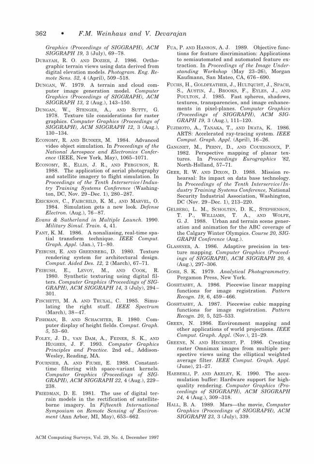
Graphics (Proceedings of SIGGRAPH), ACMSIGGRAPH 19, 3 (July), 69–78.
DUBAYAH, R. O. AND DOZIER, J. 1986. Ortho-graphic terrain views using data derived fromdigital elevation models. Photogram. Eng. Re-mote Sens. 52, 4 (April), 509–518.
DUNGAN, W. 1979. A terrain and cloud com-puter image generation model. ComputerGraphics (Proceedings of SIGGRAPH), ACMSIGGRAPH 13, 2 (Aug.), 143–150.
DUNGAN, W., STENGER, A., AND SUTTY, G.1978. Texture tile considerations for rastergraphics. Computer Graphics (Proceedings ofSIGGRAPH), ACM SIGGRAPH 12, 3 (Aug.),130–134.
ECONOMY, R. AND BUNKER, M. 1984. Advancedvideo object simulation. In Proceedings of theNational Aerospace and Electronics Confer-ence (IEEE, New York, May), 1065–1071.
ECONOMY, R., ELLIS, J. R., AND FERGUSON, R.1988. The application of aerial photographyand satellite imagery to flight simulation. InProceedings of the Tenth Interservice/Indus-try Training Systems Conference (Washing-ton, DC, Nov. 29–Dec. 1), 280–287.
ERICKSON, C., FAIRCHILD, K. M., AND MARVEL, O.1984. Simulation gets a new look. DefenseElectron. (Aug.), 76–87.
Evans & Sutherland in Multiple Launch. 1990.Military Simul. Train. 4, 41.
FANT, K. M. 1986. A nonaliasing, real-time spa-tial transform technique. IEEE Comput.Graph. Appl. (Jan.), 71–80.
FEIBUSH, E. AND GREENBERG, D. 1980. Texturerendering system for architectural design.Comput. Aided Des. 12, 2 (March), 67–71.
FEIBUSH, E., LEVOY, M., AND COOK, R.1980. Synthetic texturing using digital fil-ters. Computer Graphics (Proceedings of SIG-GRAPH), ACM SIGGRAPH 14, 3 (July), 294–301.
FISCHETTI, M. A. AND TRUXAL, C. 1985. Simu-lating the right stuff. IEEE Spectrum(March), 38–47.
FISHMAN, B. AND SCHACHTER, B. 1980. Com-puter display of height fields. Comput. Graph.5, 53–60.
FOLEY, J. D., VAN DAM, A., FEINER, S. K., ANDHUGHES, J. F. 1993. Computer GraphicsPrinciples and Practice. 2nd ed., Addison-Wesley, Reading, MA.
FOURNIER, A. AND FIUME, E. 1988. Constant-time filtering with space-variant kernels.Computer Graphics (Proceedings of SIG-GRAPH), ACM SIGGRAPH 22, 4 (Aug.), 229–238.
FRIEDMAN, D. E. 1981. The use of digital ter-rain models in the rectification of satellite-borne imagery. In Fifteenth InternationalSymposium on Remote Sensing of Environ-ment (Ann Arbor, MI, May), 653–662.
FUA, P. AND HANSON, A. J. 1989. Objective func-tions for feature discrimination: Applicationsto semiautomated and automated feature ex-traction. In Proceedings of the Image Under-standing Workshop (May 23–26), MorganKaufmann, San Mateo, CA, 676–690.
FUCHS, H., GOLDFEATHER, J., HULTQUIST, J., SPACH,S., AUSTIN, J., BROOKS, F., EYLES, J., AND
POULTON, J. 1985. Fast spheres, shadows,textures, transparencies, and image enhance-ments in pixel-planes. Computer Graphics(Proceedings of SIGGRAPH), ACM SIG-GRAPH 19, 3 (Aug.), 111–120.
FUJIMOTO, A., TANAKA, T., AND IWATA, K. 1986.ARTS: Accelerated ray-tracing system. IEEEComput. Graph. Appl. (April), 16–26.
GANGNET, M., PERNY, D., AND COUEIGNOUX, P.1982. Perspective mapping of planar tex-tures. In Proceedings Eurographics ’82,North-Holland, 57–71.
GEER, R. W. AND DIXON, D. 1988. Mission re-hearsal: Its impact on data base technology.In Proceedings of the Tenth Interservice/In-dustry Training Systems Conference, NationalSecurity Industrial Association, Washington,DC (Nov. 29–Dec. 1), 213–220.
GELBERG, L. M., SCHOLTEN, D. K., STEPHENSON,T. P., WILLIAMS, T. A., AND WOLFE,G. J. 1988. Urban and terrain scene gener-ation and animation for the ABC coverage ofthe Calgary Winter Olympics. Course 20, SIG-GRAPH Conference (Aug.).
GLASSNER, A. 1986. Adaptive precision in tex-ture mapping. Computer Graphics (Proceed-ings of SIGGRAPH), ACM SIGGRAPH 20, 4(Aug.), 297–306.
GOSH, S. K. 1979. Analytical Photogrammetry.Pergamon Press, New York.
GOSHTASBY, A. 1986. Piecewise linear mappingfunctions for image registration. PatternRecogn. 19, 6, 459–466.
GOSHTASBY, A. 1987. Piecewise cubic mappingfunctions for image registration. PatternRecogn. 20, 5, 525–533.
GREEN, N. 1986. Environment mapping andother applications of world projections. IEEEComput. Graph. Appl. (Nov.), 21–29.
GREENE, N. AND HECKBERT, P. 1986. Creatingraster Omnimax images from multiple per-spective views using the elliptical weightedaverage filter. IEEE Comput. Graph. Appl.(June), 21–27.
HAEBERLI, P. AND AKELEY, K. 1990. The accu-mulation buffer: Hardware support for high-quality rendering. Computer Graphics (Pro-ceedings of SIGGRAPH), ACM SIGGRAPH24, 4 (Aug.), 309–318.
HALL, B. A. 1989. Mars—the movie, ComputerGraphics (Proceedings of SIGGRAPH), ACMSIGGRAPH 23, 3 (July), 339.
362 • F.M. Weinhaus and V. Devarajan
ACM Computing Surveys, Vol. 29, No. 4, December 1997

HANSON, A. J. AND QUAM, L. H. 1988. Overviewof the SRI cartographic modeling environ-ment. In Proceedings of the Image Under-standing Workshop, Morgan Kaufmann, SanMateo, CA, 576–582.
HANSON, A. J., PENTLAND, A. P., AND QUAM,L. H. 1987. Design of a prototype interac-tive cartographic display and analysis envi-ronment. In Proceedings of the Image Under-standing Workshop, (Feb.), MorganKaufmann, San Mateo, CA, 475–482.
HECKBERT, P. 1983. Texture mapping polygonsin perspective. Tech. Memo No. 13, ComputerGraphics Lab, New York Institute of Technol-ogy, April 28.
HECKBERT, P. 1986a. Filtering by repeated inte-gration. Computer Graphics (Proceedings ofSIGGRAPH), ACM SIGGRAPH 20, 4 (Aug.),315–321.
HECKBERT, P. S. 1986b. Survey of texture map-ping. IEEE Comput. Graph. Appl. (Sept.), 56–67.
HECKBERT, P. S. 1989. Fundamentals of texturemapping and image warping. Masters Thesis,Computer Science Division, University of Cal-ifornia, Report No. UCB/CSD 89/516.
HECKBERT, P. S. AND MORETON, H. P. 1991. In-terpolation for polygon texture mapping andshading. In State of the Art in ComputerGraphics: Visualization and Modeling, D. F.Rogers and R. A. Earnshaw, Eds., Springer-Verlag, New York, 101–111.
HERMAN, M. AND KANADE, T. 1986. Incrementalreconstruction of 3D scenes from multiple,complex images. Artif. Intell. 30, 289–341.
HOOD, J., LADNER, L., AND CHAMPION, R. 1989.Image processing techniques for digital or-thophotoquad production. Photogram. Eng.Remote Sens. 55, 9 (Sept.), 1323–1329.
HOOKS, J. T. AND DEVARAJAN, V. 1981a. Simu-lated FLIR imagery using computer animatedphotographic terrain views. In Proceedings ofIMAGE Conference II, The IMAGE Society(Tempe, AZ, June 10–12), 25–34.
HOOKS, J. T. AND DEVARAJAN, V. 1981b. Digitalprocessing of color photography for visualsimulations. In Proceedings of the Third In-terservice/Industry Training Equipment andExhibition, National Security Industrial Asso-ciation (Washington, DC, Nov. 30–Dec. 2),47–55.
HOOKS, J. T., MARTINSEN, G. J., AND DEVARAJAN,V. 1990. On 3-D perspective generationfrom a multi-resolution photo mosaic database. In Proceedings of IMAGE Conference V,The IMAGE Society (Tempe, AZ, June 19–22),132–143.
HOPKINS, R. R. AND COOPER, M. B. 1988. Mak-ing clouds. In Proceedings of the Tenth In-terservice/Industry Training Systems Confer-
ence, National Security Industrial Association(Washington, DC, Nov. 29–Dec. 1), 209–212.
HOURCADE, J. C. AND NICOLAS, A. 1983. Inverseperspective mapping in scanline order ontonon-planar quadrilaterals. In Proceedings Eu-rographics ’83, North-Holland, 309–319.
HUGHES, P. 1991. Building a terrain renderer.Comput. Phys. (July/Aug.), 434–437.
HUSSEY, K. J., HALL, J. R., AND MORTENSEN,R. A. 1986. Image processing methods intwo and three dimensions used to animateremotely sensed data. In Proceedings ofIGARSS ’86 Symposium, IEEE Service CenterCat. No. 86CH2268-1 (Piscataway, NJ, Sept.8–11) 771–776.
HUSSEY, K., MORTENSEN, B., AND HALL, J. 1987.LA—the movie. Computer Graphics (Proceed-ings of SIGGRAPH), ACM SIGGRAPH 21, 6(Nov.), Appendix E, ViSC Videotape: List ofContributors, E-2.
INMAN, R. AND MCMILLAN, D. 1990. The state ofthe art in image processing: Visualization.Aerospace Defense Sci. (Nov./Dec.), 45–48.
IRVIN, R. B. AND MCKEOWN, D. M. 1989. Meth-ods for exploiting the relationship betweenbuildings and their shadows in aerial imag-ery. In Proceedings of SPIE (Bellingham,WA), Vol. 1076, 156–164.
JUNKIN, B. G. 1982. Development of three-di-mensional spatial displays using a geographi-cally based information system. Photogram.Eng. Remote Sens. 48, 4 (April), 577–586.
KANEDA, K., KATO, F., NAKAMAE, E., NISHITA, T.,TANAKA, H., AND NOGUCHI, T. 1989. Threedimensional terrain modeling and display forenvironmental assessment. Computer Graph-ics (Proceedings of SIGGRAPH), ACM SIG-GRAPH 23, 3 (July), 207–212.
KIRK, D. AND VOORHIES, D. 1990. The renderingarchitecture of the DN10000VS. ComputerGraphics (Proceedings of SIGGRAPH), ACMSIGGRAPH 24, 4 (Aug.), 299–307.
LEE, D. AND SCHACHTER, B. 1980. Two algo-rithms for constructing a Delaunay triangula-tion. Int. J. Comput. Inf. Sci. 9, 3, 219–242.
LIEN, S., SHANTZ, M., AND PRATT, V. 1987.Adaptive forward differencing for renderingcurves and surfaces. Computer Graphics (Pro-ceedings of SIGGRAPH), ACM SIGGRAPH21, 4 (July), 111–118.
LIPPMAN, A. 1980. Movie-maps: An applicationof the optical videodisk to computer graphics.Computer Graphics (Proceedings of SIG-GRAPH), ACM SIGGRAPH 14, 3 (July), 32–42.
MAGNENAT-THALMANN, N. AND THALMANN, D.1987. Image Synthesis—Theory and Prac-tice. Springer-Verlag, Tokyo.
MCMILLAN, T. 1988. Graphics for the task.Comput. Graph. World (Aug.), 69–71.
Texture Mapping 3D Models • 363
ACM Computing Surveys, Vol. 29, No. 4, December 1997

MILLER, G. 1986. The definition and renderingof terrain maps. Computer Graphics (Proceed-ings of SIGGRAPH), ACM SIGGRAPH 20, 4(Aug.), 39–48.
MOLNAR, S., EYLES, J., AND POULTON, J. 1992.Pixel Flow: High-speed rendering using imagecomposition. Computer Graphics (Proceedingsof SIGGRAPH), ACM SIGGRAPH 26, 2(July), 231–240.
MORTENSEN, H. B., HUSSEY, K. J., AND MORTENSEN,R. A. 1988. Image processing methods usedto simulate flight over remotely sensed data.In Proceedings of the 20th Annual SummerComputer Simulation Conference, (San Diego,CA, July 25–28), 719–722.
MUDUNURI, B. K. 1989. Photogrammetric appli-cations in visual data base generation for parttask trainers. In Proceedings of the 12th Bien-nial Workshop on Color Aerial Photographyand Videography in the Planetary Sciencesand Related Fields, American Society for Pho-togrammetry and Remote Sensing (Bethesda,MD, May 23–26), 227–235.
MUDUNURI, B. K. AND HOOKS, J. T. 1985. Analgorithm for generation of super wide field ofview scanned images. In Proceedings of the38th Annual SPSE Conference (Springfield,VA, May 12–16), 154–158.
MUELLER, W. J. AND OLSON, J. A. 1993. Model-based feature extraction. In Proceedings ofSPIE (Bellingham, WA), Vol. 1994, paper #26.
NACK, M. L., BATTAGLIA, M. P., AND NATHAN,A. 1989a. Real time perspective image gen-eration. In Proceedings of SPIE (Bellingham,WA), Vol. 1075, 244–249. Also in SPIE/SPSESymposium on Electronic Imaging (Belling-ham, WA, Jan.) 15–20.
NACK, M. L., NATHAN, A. R., AND NATHAN, R.1989b. Parallel processing applied to imageprocessing and perspective scene generation.In Proceedings of Electronic Imaging West1989 Symposium, The Institute for GraphicCommunications (Boston, MA, April), 1–6.
NORTON, A., ROCKWOOD, A. P., AND SKOLMOSKI,P. T. 1982. Clamping: A method of anti-aliasing textured surfaces by bandwidth lim-iting in object space. Computer Graphics (Pro-ceedings of SIGGRAPH), ACM SIGGRAPH16, 3 (July), 1–8.
OKA, M., TSUTSUI, K., OHBA, A., KURAUCHI, Y., ANDTAGO, T. 1987. Real-time manipulation oftexture-mapped surfaces. Computer Graphics(Proceedings of SIGGRAPH), ACM SIG-GRAPH 21, 4 (July), 181–188.
PAGLIERONI, D. W. 1992. A unified distancetransform algorithm and architecture. Mach.Visioin Appl. 5, 47–55.
PAGLIERONI, D. W. AND PETERSON, S. M. 1992.Parametric height field ray tracing. In Pro-ceedings Graphics Interface ’92 (Toronto,May), 192–200.
PAINTER, J. AND SLOAN, K. 1989. Antialiased
ray tracing by adaptive progressive refine-ment. Computer Graphics (Proceedings ofSIGGRAPH), ACM SIGGRAPH 23, 3 (Aug.),281–286.
PARESCHI, M. T. AND BERNSTEIN, R. 1989.Modeling and image processing for visualiza-tion of volcanic mapping. IBM J. Res. Dev. 33,4 (July), 406–416.
PELED, A. AND SHMUTTER, B. 1984. Analyticalgeneration of orthophotos from panoramicphotographs. Photogram. Eng. Remote Sens.50, 2 (Feb.), 184–192.
PERNY, D., GANGNET, M., AND COUEIGNOUX, P.1982. Perspective mapping of planar tex-tures. Computer Graphics (Proceedings ofSIGGRAPH), ACM SIGGRAPH 16, 1 (May),70–100.
PETERSEN, S. M., BARRETT, W. A., AND BURTON,R. P. 1990. A new morphological algorithmfor automated interpolation of height gridsfrom contour images. In Proceedings of SPIE(Bellingham, WA), Vol. 1256, 62–72.
PINEDA, J. 1988. A parallel algorithm for poly-gon rasterization. Computer Graphics (Pro-ceedings of SIGGRAPH), ACM SIGGRAPH22, 4 (Aug.), 17–20.
RICH, H. 1989. Tradeoffs in creating a low-costvisual simulator. In Proceedings of the 11thInterservice/Industry Training Systems Con-ference (Washington, DC, Nov.), 214–223.
RIFMAN, S. 1973. Digital rectification of ERTSmultispectral imagery. In Proceedings of theSymposiuim on Significant Results Obtainedfrom the ERTS-1, NASA SP-327, Vol. 1, Sec. B(March), 1131–1142.
ROBERTSON, P. 1989. Spatial transformationsfor rapid scan-line surface shadowing. IEEEComput. Graph. Appl. (July), 35–42.
ROBERTSON, P. K. 1987. Fast perspective viewsof images using one-dimensional operations.IEEE Comput. Graph. Appl. (Feb.), 47–56.
ROBINSON, J. AND ZIMMERMAN, S. 1985. Exploit-ing texture in an integrated training environ-ment. In Proceedings of the Seventh Interser-vice/Industry Training Systems Conference(Washington, DC, Nov. 19–21), 113–121.
ROGERS, D. 1985. Procedural Elements for Com-puter Graphics. McGraw-Hill, New York.
ROSS, M. K. 1990. Imaging and graphics meeton the battlefield. Adv. Imag. (Feb.), 52–54, 75.
SAMET, H. AND WEBBER, R. 1988a. Hierarchicaldata structures and algorithms for computergraphics—part 1: Fundamentals. IEEE Com-put. Graph. Appl. (May), 48–68.
SAMET, H. AND WEBBER, R. 1988b. Hierarchicaldata structures and algorithms for computergraphics—part 2: Applications. IEEE Comput.Graph. Appl. (July), 59–75.
SCHACHTER, B. J. AND AHUJA, N. 1980. A historyof visual flight simulation. Comput. Graph.World 3, 3 (May), 16–31.
364 • F.M. Weinhaus and V. Devarajan
ACM Computing Surveys, Vol. 29, No. 4, December 1997

SCHACHTER, B. J. 1981. Computer image gener-ation for flight simulation. IEEE Comput.Graph. Appl. (Oct.), 29–63.
SCOTT, W. B. 1983. Image system to unite com-puter, video. Aviation Week Space Technol.(May 16), 70–73.
SCUDERI, L. AND STROME, W. M. 1988. Bringingremote sensing down to earth. Adv. Imag.(Sept.), 44–50.
SEGAL, M., KOROBKIN, C., VAN WIDENFELT, R., FO-RAN, J., AND HAEBERLI, P. 1992. Fast shad-ows and lighting effects using texture map-ping. Computer Graphics (Proceedings ofSIGGRAPH), ACM SIGGRAPH 26, 2 (July),249–252.
SHANTZ, M. AND LIEN, S. 1987. Shading bicubicpatches. Computer Graphics (Proceedings ofSIGGRAPH), ACM SIGGRAPH 21, 4 (July),189–196.
SMEDLEY, K., HAINES, B., VAN VACTOR, D., ANDJORDAN, M. 1989. Digital perspective gen-eration and stereo display of composite oceanbottom and coastal terrain images. In Pro-ceedings of SPIE (Bellingham, WA), Vol.1083, 246–250.
SMITH, A. R. 1987. Planar 2-pass texture map-ping and warping. Computer Graphics (Pro-ceedings of SIGGRAPH), ACM SIGGRAPH21, 4 (July), 263–272.
STANFILL, D. F. 1991. Using image pyramids forthe visualization of large terrain data sets.Int. J. Image Syst. Technol. 157–166.
SUN MICROSYSTEMS. 1989. MAPVU demo pack-age documentation. TAAC-1 Software Refer-ence Manual, Apr. 15, Section 18, 36–40.
SWANSON, R. AND THAYER, L. 1986. A fast shad-ed-polygon renderer. Computer Graphics (Pro-ceedings of SIGGRAPH), ACM SIGGRAPH20, 4 (Aug.), 95–101.
TANAKA, S. 1979. Landscape drawings fromLANDSAT MSS data. Photogram. Eng. Re-mote Sens. 45, 10 (Oct.), 1345–1351.
TANIMOTO, S. L. AND PAVLIDIS, T. 1975. A hier-archical data structure for picture processing.Comput. Graph. Image Process. 4, 2, 104–119.
THOMPSON, M. M., ED. 1966. Manual of Photo-grammetry. American Society of Photogram-metry, Falls Church, VA.
TUCKER, J. B. 1984. Visual simulation takesflight. High Technol. (Dec.), 34–47.
UPSTILL, S. 1990. The Renderman Companion.Addison-Wesley, Reading, MA.
VAN WIE, P. AND STEIN, M. 1977. A LANDSATdigital image rectification system. IEEEGeosci. Electron. GE-15, 3 (July), 130–137.
VOLOTTA, T. A. 1991. Mars navigator. Comput.Phys. (May/June), 283–284.
WALKER, E. L. AND HERMAN, M. 1988. Geomet-ric reasoning for constructing 3D scene de-scriptions from images. Artif. Intell. 37, 275–290.
WALTERMAN, M. AND WEINHAUS, F. 1991. Anti-aliasing warped imagery using look-up tablebased methods for adaptive resampling. InProceedings of SPIE (Bellingham, WA, July),Vol. 1567, 204–214.
WANG, S. L. AND STAUDHAMMER, J. 1990. Visi-bility determination on projected grid sur-faces. IEEE Comput. Graph. Appl. (July),36 – 43.
WEINHAUS, F. AND WALTERMAN, M. 1990. A flex-ible approach to image warping. In Proceed-ings of SPIE (Bellingham, WA, Feb.), Vol.1244, 108–122.
WEINHAUS, F. M. AND DEVICH, R. N. 1997. Pho-togrammetric texture mapping onto planarpolygons. Graph. Models Image Process. (Sub-mitted for publication).
WHITESIDE, A. E. 1989. Preparing data basesfor perspective scene generation. In Proceed-ings of SPIE (Bellingham, WA), Vol. 1075,230–237.
WHITESIDE, A., ELLIS, M., AND HASKELL, B. 1987.Digital generation of stereoscopic perspectivescenes. In Proceedings of SPIE (Bellingham,WA), Vol. 761, 172–178.
WILLIAMS, L. 1983. Pyramidal parametrics.Computer Graphics (Proceedings of SIG-GRAPH), ACM SIGGRAPH 17, 3 (July), 1–11.
WOLBERG, G. 1990. Digital Image Warping.IEEE Computer Society Press, Los Alamitos,CA.
YAN, J. K. 1985. Advances in computer-gener-ated imagery for flight simulation. IEEEComput. Graph. Appl. (Aug.), 37–51.
Received February 1996; revised April 1997; accepted May 1997
Texture Mapping 3D Models • 365
ACM Computing Surveys, Vol. 29, No. 4, December 1997