Embed Size (px)
Citation preview

Texas Instruments
Power & Interface Solutions for Field Transmitters
Giovanni Campanella Systems Engineer // Factory Automation & Control
November 2017
This webinar will answer:
• What isolated ultra-low power solutions can I use for a field transmitter?
• How can I harvest energy from a 4-20mA loop to power other devices?
• How can I implement a wireless user interface from a 4-20mA interface?
• How can I increase system scalability by integrating several protocol in one IC?
2

What is a TIDesign?
3
A web folder Documented results Schematics LMX2594
Wideband PLL
- go beyond the product datasheet to show how to solve a common problem, use in
a sub-system or how a device performs in a specific application
Design Files
Find everything in one
place

Isolated ultra-low power solutions
4
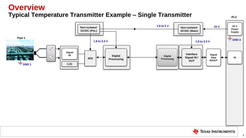
Overview Typical Temperature Transmitter Example – Single Transmitter
5
AFE
Non-isolated
DC/DC (Main)
Digital
Processing
Signal
Data
IN/OUT
Interface
Signal IN /
OUT
Digital
Processing
Non-isolated
DC/DC (PoL)
Signal
IN
CJC
24 V
Power
Supply
IN
24 V
1.8 to 3.3 V 1.8 to 3.3 V
Pipe 1
GND 1
GND 3
PLC
1.8 to 5 V
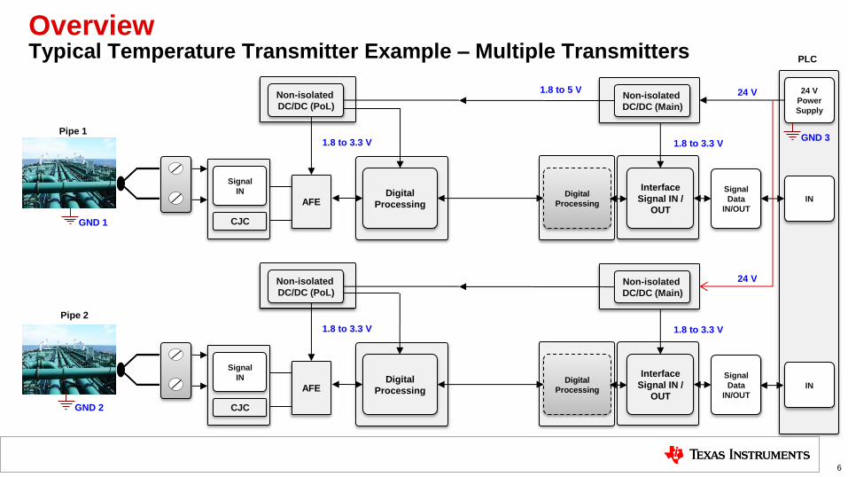
Overview Typical Temperature Transmitter Example – Multiple Transmitters
6
AFE
Non-isolated
DC/DC (Main)
Digital
Processing
Signal
Data
IN/OUT
Interface
Signal IN /
OUT
Digital
Processing
Non-isolated
DC/DC (PoL)
Signal
IN
CJC
24 V
Power
Supply
IN
24 V
1.8 to 3.3 V 1.8 to 3.3 V
AFE
Non-isolated
DC/DC (Main)
Digital
Processing
Signal
Data
IN/OUT
Interface
Signal IN /
OUT
Digital
Processing
Non-isolated
DC/DC (PoL)
Signal
IN
CJC
24 V
1.8 to 3.3 V 1.8 to 3.3 V
IN
Pipe 1
Pipe 2
GND 1
GND 2
GND 3
PLC
1.8 to 5 V
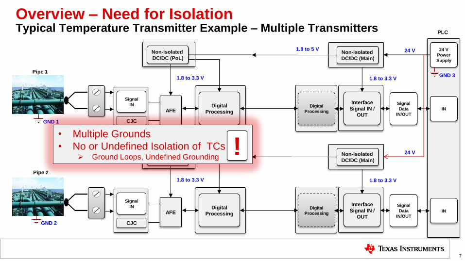
Overview – Need for Isolation Typical Temperature Transmitter Example – Multiple Transmitters
7
AFE
Non-isolated
DC/DC (Main)
Digital
Processing
Signal
Data
IN/OUT
Interface
Signal IN /
OUT
Digital
Processing
Non-isolated
DC/DC (PoL)
Signal
IN
CJC
24 V
Power
Supply
IN
24 V
1.8 to 3.3 V 1.8 to 3.3 V
AFE
Non-isolated
DC/DC (Main)
Digital
Processing
Signal
Data
IN/OUT
Interface
Signal IN /
OUT
Digital
Processing
Non-isolated
DC/DC (PoL)
Signal
IN
CJC
24 V
1.8 to 3.3 V 1.8 to 3.3 V
IN
Pipe 1
Pipe 2
GND 1
GND 2
GND 3
PLC
1.8 to 5 V
• Multiple Grounds
• No or Undefined Isolation of TCs Ground Loops, Undefined Grounding
!
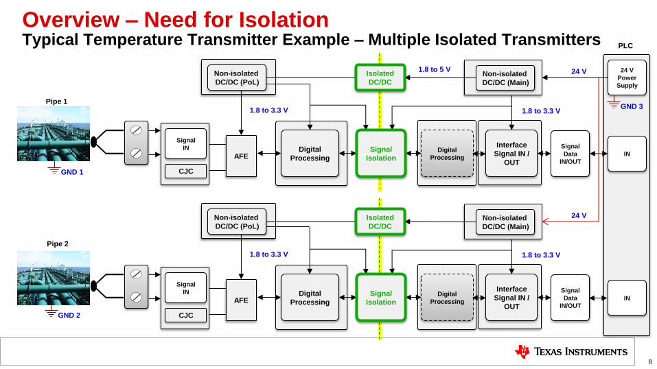
Overview – Need for Isolation Typical Temperature Transmitter Example – Multiple Isolated Transmitters
8
AFE
Non-isolated
DC/DC (Main)
Digital
Processing
Signal
Data
IN/OUT
Interface
Signal IN /
OUT
Digital
Processing
Non-isolated
DC/DC (PoL)
Signal
IN
CJC
24 V
Power
Supply
IN
24 V
1.8 to 3.3 V 1.8 to 3.3 V
AFE
Non-isolated
DC/DC (Main)
Digital
Processing
Signal
Data
IN/OUT
Interface
Signal IN /
OUT
Digital
Processing
Non-isolated
DC/DC (PoL)
Signal
IN
CJC
24 V
1.8 to 3.3 V 1.8 to 3.3 V
IN
Pipe 1
Pipe 2
GND 1
GND 2
GND 3
PLC
1.8 to 5 V
Isolated
DC/DC
Signal
Isolation
Isolated
DC/DC
Signal
Isolation
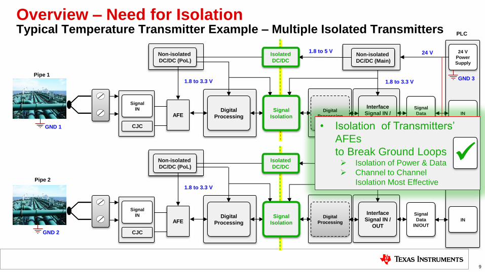
Overview – Need for Isolation Typical Temperature Transmitter Example – Multiple Isolated Transmitters
9
AFE
Non-isolated
DC/DC (Main)
Digital
Processing
Signal
Data
IN/OUT
Interface
Signal IN /
OUT
Digital
Processing
Non-isolated
DC/DC (PoL)
Signal
IN
CJC
24 V
Power
Supply
IN
24 V
1.8 to 3.3 V 1.8 to 3.3 V
AFE
Non-isolated
DC/DC (Main)
Digital
Processing
Signal
Data
IN/OUT
Interface
Signal IN /
OUT
Digital
Processing
Non-isolated
DC/DC (PoL)
Signal
IN
CJC
24 V
1.8 to 3.3 V 1.8 to 3.3 V
IN
Pipe 1
Pipe 2
GND 1
GND 2
GND 3
PLC
• Isolation of Transmitters’
AFEs
to Break Ground Loops Isolation of Power & Data
Channel to Channel
Isolation Most Effective
1.8 to 5 V
Isolated
DC/DC
Signal
Isolation
Isolated
DC/DC
Signal
Isolation
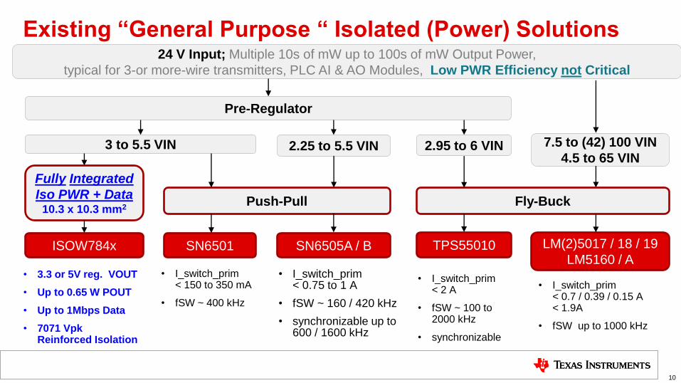
Existing “General Purpose “ Isolated (Power) Solutions
10
24 V Input; Multiple 10s of mW up to 100s of mW Output Power,
typical for 3-or more-wire transmitters, PLC AI & AO Modules, Low PWR Efficiency not Critical
Pre-Regulator
SN6501 SN6505A / B
• I_switch_prim < 150 to 350 mA
• fSW ~ 400 kHz
• I_switch_prim < 0.75 to 1 A
• fSW ~ 160 / 420 kHz
• synchronizable up to 600 / 1600 kHz
Push-Pull Fly-Buck
TPS55010
• I_switch_prim < 2 A
• fSW ~ 100 to 2000 kHz
• synchronizable
LM(2)5017 / 18 / 19
LM5160 / A
• I_switch_prim < 0.7 / 0.39 / 0.15 A < 1.9A
• fSW up to 1000 kHz
Fully Integrated
Iso PWR + Data 10.3 x 10.3 mm2
• 3.3 or 5V reg. VOUT
• Up to 0.65 W POUT
• Up to 1Mbps Data
• 7071 Vpk Reinforced Isolation
ISOW784x
3 to 5.5 VIN 2.25 to 5.5 VIN 2.95 to 6 VIN 7.5 to (42) 100 VIN
4.5 to 65 VIN
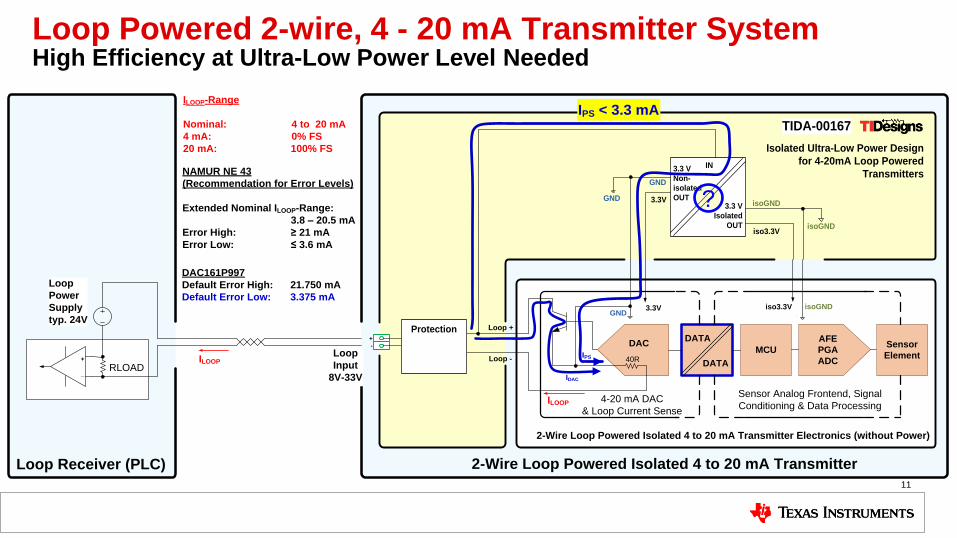
Loop Powered 2-wire, 4 - 20 mA Transmitter System High Efficiency at Ultra-Low Power Level Needed
11
Loop -
Loop +
4-20 mA DAC
& Loop Current Sense
40R
+
- DATA
DATA
MCU
AFE
PGA
ADC
Sensor
Element
3.3VGND
DAC
iso3.3V isoGND
+
_
Loop Receiver (PLC)
RLOAD
2-Wire Loop Powered Isolated 4 to 20 mA Transmitter Electronics (without Power)
Sensor Analog Frontend, Signal
Conditioning & Data Processing
Loop
Input
8V-33V
2-Wire Loop Powered Isolated 4 to 20 mA Transmitter
ILOOP
ILOOP
Loop
Power
Supply
typ. 24V
ILOOP-Range
Nominal: 4 to 20 mA
4 mA: 0% FS
20 mA: 100% FS
NAMUR NE 43
(Recommendation for Error Levels)
Extended Nominal ILOOP-Range:
3.8 – 20.5 mA
Error High: ≥ 21 mA
Error Low: ≤ 3.6 mA
DAC161P997
Default Error High: 21.750 mA
Default Error Low: 3.375 mA
IDAC
IPS < 3.3 mA
Isolated Ultra-Low Power Design
for 4-20mA Loop Powered
Transmitters IN
3.3 V
Isolated
OUT
3.3 V
Non-
isolated
OUT3.3V
GND
iso3.3V
isoGND
isoGND
GND
Protection
TIDA-00167
IPS
?
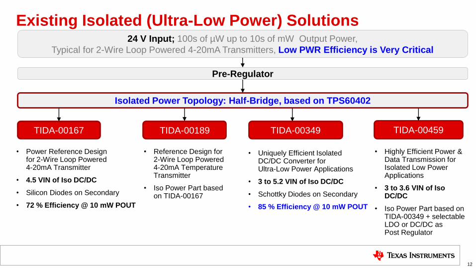
Existing Isolated (Ultra-Low Power) Solutions
12
24 V Input; 100s of µW up to 10s of mW Output Power,
Typical for 2-Wire Loop Powered 4-20mA Transmitters, Low PWR Efficiency is Very Critical
Pre-Regulator
TIDA-00189 TIDA-00349
• Reference Design for 2-Wire Loop Powered 4-20mA Temperature Transmitter
• Iso Power Part based on TIDA-00167
Isolated Power Topology: Half-Bridge, based on TPS60402
TIDA-00459
• Highly Efficient Power & Data Transmission for Isolated Low Power Applications
• 3 to 3.6 VIN of Iso DC/DC
• Iso Power Part based on TIDA-00349 + selectable LDO or DC/DC as Post Regulator
• Power Reference Design for 2-Wire Loop Powered 4-20mA Transmitter
• 4.5 VIN of Iso DC/DC
• Silicon Diodes on Secondary
• 72 % Efficiency @ 10 mW POUT
TIDA-00167
• Uniquely Efficient Isolated DC/DC Converter for Ultra-Low Power Applications
• 3 to 5.2 VIN of Iso DC/DC
• Schottky Diodes on Secondary
• 85 % Efficiency @ 10 mW POUT
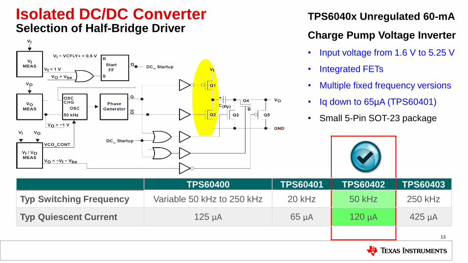
Isolated DC/DC Converter Selection of Half-Bridge Driver
13
TPS60400 TPS60401 TPS60402 TPS60403
Typ Switching Frequency Variable 50 kHz to 250 kHz 20 kHz 50 kHz 250 kHz
Typ Quiescent Current 125 μA 65 μA 120 μA 425 μA
TPS6040x Unregulated 60-mA
Charge Pump Voltage Inverter
• Input voltage from 1.6 V to 5.25 V
• Integrated FETs
• Multiple fixed frequency versions
• Iq down to 65µA (TPS60401)
• Small 5-Pin SOT-23 package
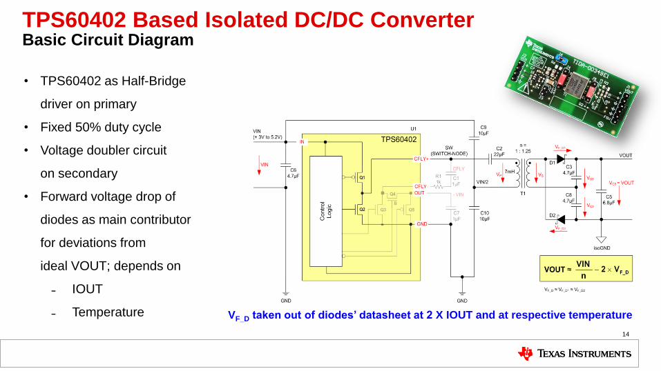
TPS60402 Based Isolated DC/DC Converter Basic Circuit Diagram
14
• TPS60402 as Half-Bridge
driver on primary
• Fixed 50% duty cycle
• Voltage doubler circuit
on secondary
• Forward voltage drop of
diodes as main contributor
for deviations from
ideal VOUT; depends on
˗ IOUT
˗ Temperature
VF_D taken out of diodes’ datasheet at 2 X IOUT and at respective temperature
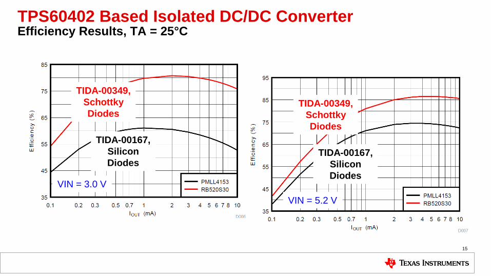
TPS60402 Based Isolated DC/DC Converter Efficiency Results, TA = 25°C
15
TIDA-00349,
Schottky
Diodes
TIDA-00167,
Silicon
Diodes
TIDA-00349,
Schottky
Diodes
TIDA-00167,
Silicon
Diodes VIN = 3.0 V
VIN = 5.2 V

4-20mA loop energy harvester
16
17
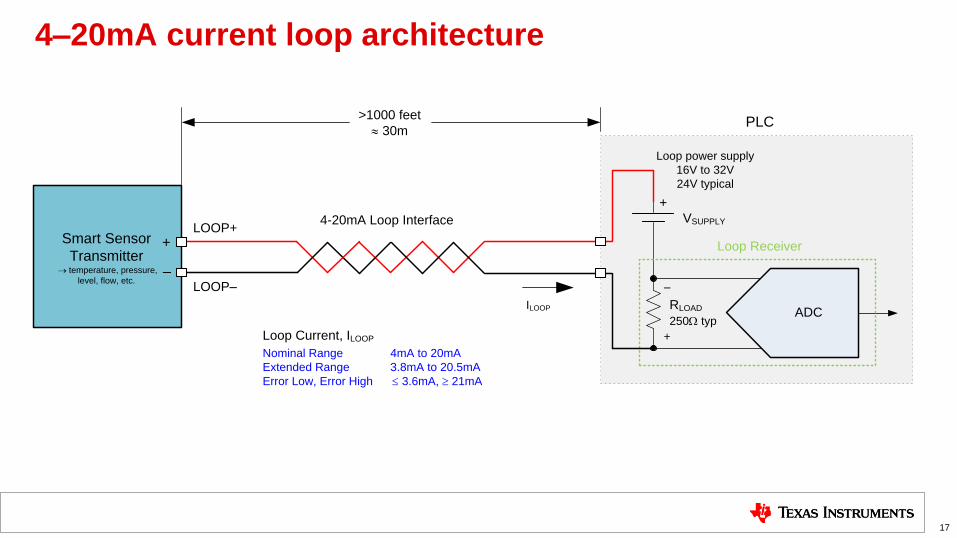
4–20mA current loop architecture
VSUPPLY
RLOAD
250W typ
Loop power supply
16V to 32V
24V typical
Smart Sensor
Transmitter ® temperature, pressure,
level, flow, etc.
+
>1000 feet
» 30m
–
+
LOOP––
+
LOOP+
PLC
4-20mA Loop Interface
Loop Current, ILOOP
Nominal Range 4mA to 20mA
Extended Range 3.8mA to 20.5mA
Error Low, Error High £ 3.6mA, ³ 21mA
ILOOP
Loop Receiver
ADC
18
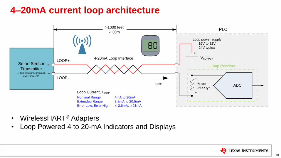
4–20mA current loop architecture
VSUPPLY
RLOAD
250W typ
Loop power supply
16V to 32V
24V typical
Smart Sensor
Transmitter ® temperature, pressure,
level, flow, etc.
+
>1000 feet
» 30m
–
+
LOOP––
+
LOOP+
PLC
4-20mA Loop Interface
Loop Current, ILOOP
Nominal Range 4mA to 20mA
Extended Range 3.8mA to 20.5mA
Error Low, Error High £ 3.6mA, ³ 21mA
ILOOP
Loop Receiver
ADC
• WirelessHART® Adapters
• Loop Powered 4 to 20-mA Indicators and Displays
19
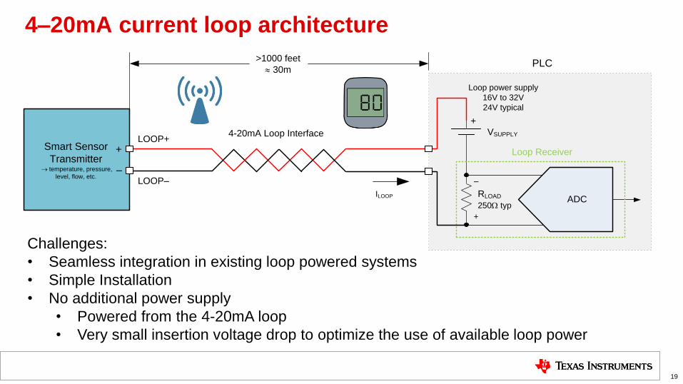
4–20mA current loop architecture
Challenges:
• Seamless integration in existing loop powered systems
• Simple Installation
• No additional power supply
• Powered from the 4-20mA loop
• Very small insertion voltage drop to optimize the use of available loop power
VSUPPLY
RLOAD
250W typ
Loop power supply
16V to 32V
24V typical
Smart Sensor
Transmitter ® temperature, pressure,
level, flow, etc.
+
>1000 feet
» 30m
–
+
LOOP––
+
LOOP+
PLC
4-20mA Loop Interface
Loop Current, ILOOP
Nominal Range 4mA to 20mA
Extended Range 3.8mA to 20.5mA
Error Low, Error High £ 3.6mA, ³ 21mA
ILOOP
Loop Receiver
ADC
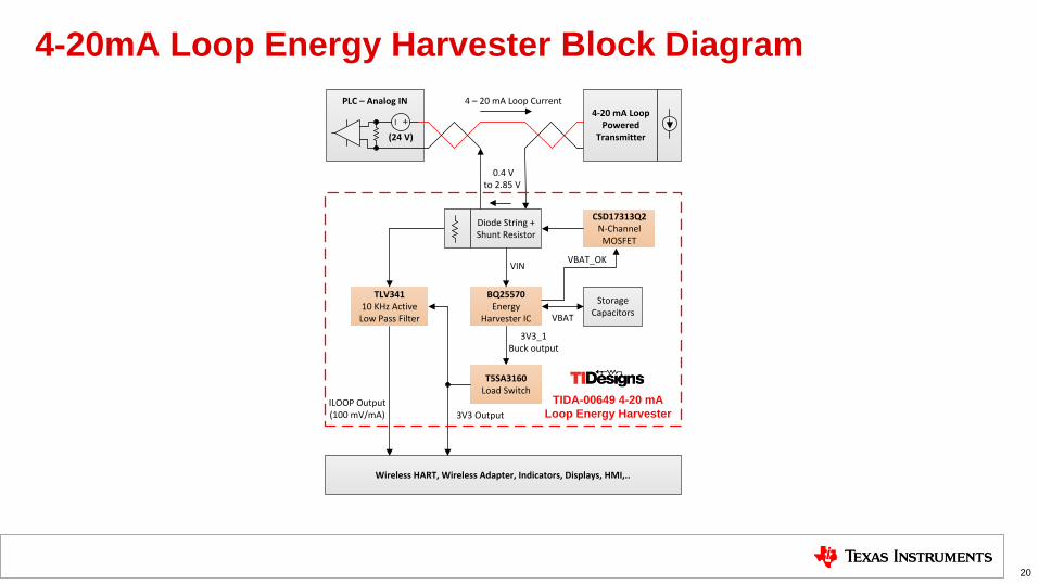
4-20mA Loop Energy Harvester Block Diagram
20
Diode String + Shunt Resistor
TLV34110 KHz Active
Low Pass Filter
BQ25570Energy
Harvester IC
T5SA3160Load Switch
Storage Capacitors
Wireless HART, Wireless Adapter, Indicators, Displays, HMI,..
TIDA-00649 4-20 mA
Loop Energy Harvester
TIDA-00649 4-20 mA
Loop Energy Harvester
VIN
VIN
0.4 V to 2.85 V
0.4 V to 2.85 V
VBAT
VBAT
3V3_1 Buck output
3V3_1 Buck output
3V3 Output
3V3 OutputILOOP Output(100 mV/mA)
ILOOP Output(100 mV/mA)
4 – 20 mA Loop Current
4 – 20 mA Loop Current4-20 mA Loop
Powered Transmitter
CSD17313Q2N-Channel MOSFET
VBAT_OK
VBAT_OK
PLC – Analog IN
(24 V)
+–
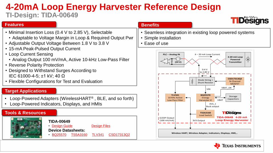
4-20mA Loop Energy Harvester Reference Design TI-Design: TIDA-00649
Tools & Resources
TIDA-00649 • Design Guide Design Files
Device Datasheets: • BQ25570 TS5A3160 TLV341 CSD17313Q2
Target Applications
• Loop-Powered Adapters (WirelessHART® , BLE, and so forth)
• Loop-Powered Indicators, Displays, and HMIs
Features
• Minimal Insertion Loss (0.4 V to 2.85 V), Selectable
• Adaptable to Voltage Margin in Loop & Required Output Pwr
• Adjustable Output Voltage Between 1.8 V to 3.8 V
• 15-mA Peak-Pulsed Output Current
• Loop Current Sensing
• Analog Output 100 mV/mA, Active 10-kHz Low-Pass Filter
• Reverse Polarity Protection
• Designed to Withstand Surges According to
IEC 61000-4-5; ±1 kV; 40 Ω
• Flexible Configurations for Test and Evaluation
Benefits
• Seamless integration in existing loop powered systems
• Simple installation
• Ease of use
Diode String + Shunt Resistor
TLV34110 KHz Active
Low Pass Filter
BQ25570Energy
Harvester IC
T5SA3160Load Switch
Storage Capacitors
Wireless HART, Wireless Adapter, Indicators, Displays, HMI,..
TIDA-00649 4-20 mA
Loop Energy Harvester
TIDA-00649 4-20 mA
Loop Energy Harvester
VIN
VIN
0.4 V to 2.85 V
0.4 V to 2.85 V
VBAT
VBAT
3V3_1 Buck output
3V3_1 Buck output
3V3 Output
3V3 OutputILOOP Output(100 mV/mA)
ILOOP Output(100 mV/mA)
4 – 20 mA Loop Current
4 – 20 mA Loop Current4-20 mA Loop
Powered Transmitter
CSD17313Q2N-Channel MOSFET
VBAT_OK
VBAT_OK
PLC – Analog IN
(24 V)
+–
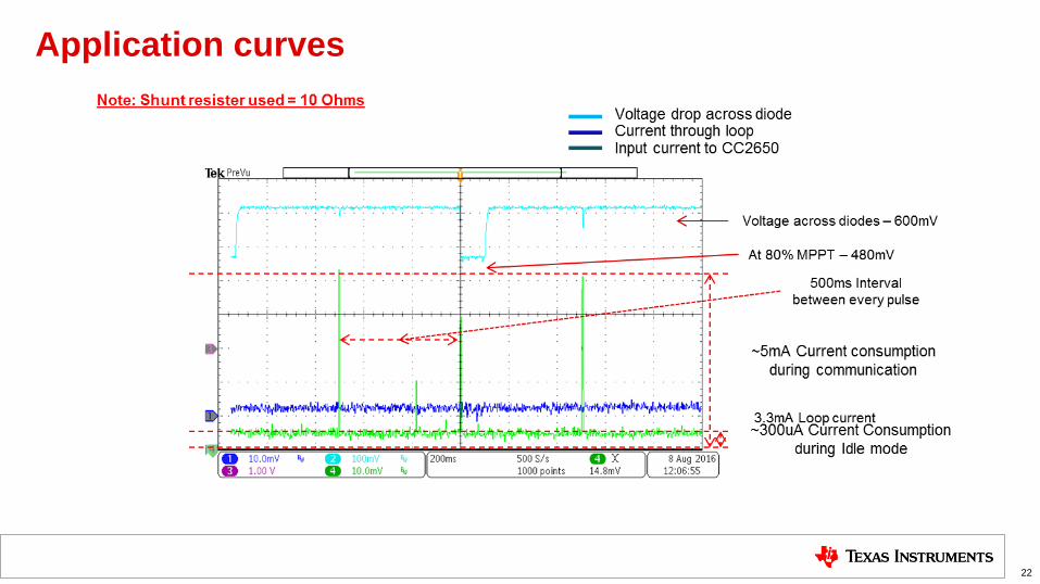
Application curves
22

Wireless HMI
23
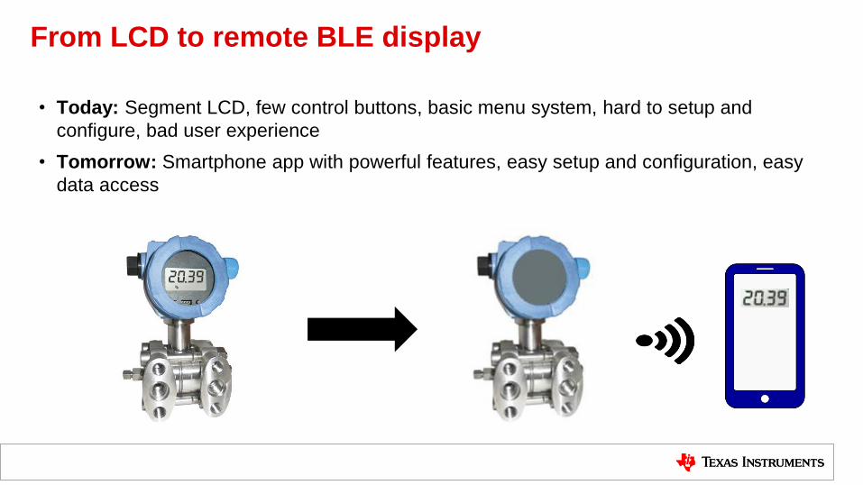
From LCD to remote BLE display
• Today: Segment LCD, few control buttons, basic menu system, hard to setup and
configure, bad user experience
• Tomorrow: Smartphone app with powerful features, easy setup and configuration, easy
data access
LM5165
J4
U5
U3 U4 20 Ω
LOOP +
LOOP -
TIDA-00666Wireless Field Transmitter powered
from 4 to 20-mA Current Loop
4-20 mA Loop
Interface
Loop Power Supply
typ. 24V
+
_
RLOAD
Loop Input Protection
Loop Reiceiver
(PLC)
ILOOP
ILOOP-Range
Nominal: 4 – 20 mA
Extended: 3.8 – 20.5 mA
Error High: ≥ 21 mA
Error Low: ≤ 3.6 mA
DAC161S997
Default Error High: 21.750 mA
Default Error Low: 3.375 mACopyright © 2016, Texas Instruments Incorporated
J8
TPS717
U6
J11
J10
HDC1080
U1
CC2650
J7
J3
I2C
DAC161S997
SPI
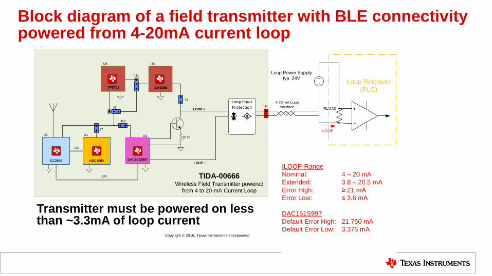
Block diagram of a field transmitter with BLE connectivity powered from 4-20mA current loop
Transmitter must be powered on less than ~3.3mA of loop current
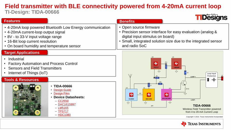
Field transmitter with BLE connectivity powered from 4-20mA current loop TI-Design: TIDA-00666
Tools & Resources
• TIDA-00666 • Design Guide
• Design Files
• Device Datasheets: ‒ CC2650
‒ DAC161S997
‒ LM5165
‒ TPS717
‒ HDC1080
Target Applications
• Industrial
• Factory Automation and Process Control
• Sensors and Field Transmitters
• Internet of Things (IoT)
Features
• 4-20mA loop powered Bluetooth Low Energy communication
• 4-20mA current-loop output signal
• 8V - to 33-V input voltage range
• 16-Bit loop current resolution
• On board humidity and temperature sensor
Benefits
• Open source firmware
• Precision sensor interface for easy evaluation (analog &
digital input stimulus on board)
• Small, integrated solution size due to the integrated sensor
and radio SoC
LM5165
J4
U5
U3 U4 20 Ω
LOOP +
LOOP -
TIDA-00666Wireless Field Transmitter powered
from 4 to 20-mA Current Loop
Loop Input Protection
Copyright © 2016, Texas Instruments Incorporated
J8
TPS717
U6
J11
J10
HDC1080
U1
CC2650
J7
J3
I2C
DAC161S997
SPI
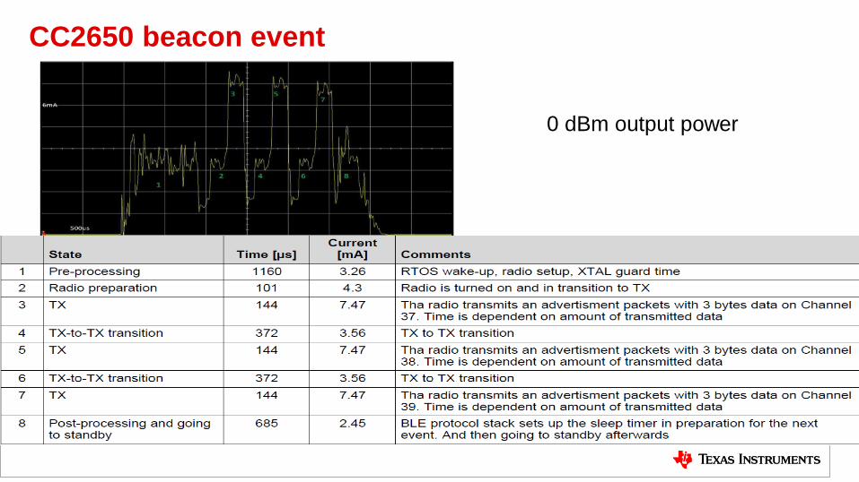
CC2650 beacon event
27
0 dBm output power
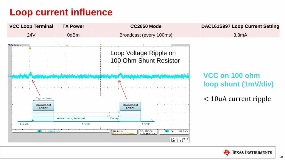
Loop current influence
28
VCC Loop Terminal TX Power CC2650 Mode DAC161S997 Loop Current Setting
24V 0dBm Broadcast (every 100ms) 3.3mA
VCC on 100 ohm
loop shunt (1mV/div)
Loop Voltage Ripple on
100 Ohm Shunt Resistor
< 10uA current ripple
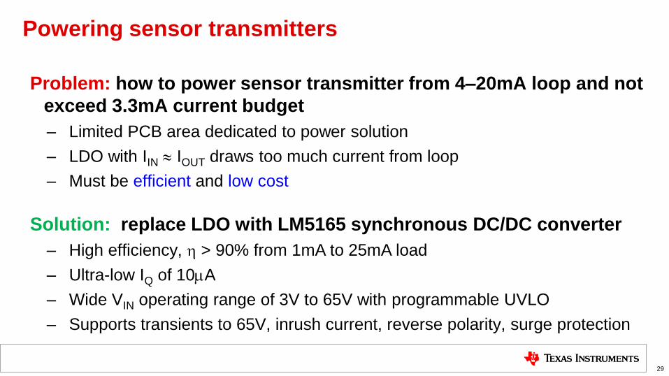
Powering sensor transmitters
Problem: how to power sensor transmitter from 4–20mA loop and not
exceed 3.3mA current budget
– Limited PCB area dedicated to power solution
– LDO with IIN » IOUT draws too much current from loop
– Must be efficient and low cost
29
Solution: replace LDO with LM5165 synchronous DC/DC converter
– High efficiency, > 90% from 1mA to 25mA load
– Ultra-low IQ of 10A
– Wide VIN operating range of 3V to 65V with programmable UVLO
– Supports transients to 65V, inrush current, reverse polarity, surge protection
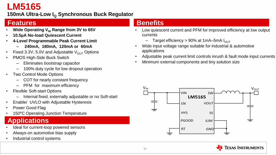
LM5165 150mA Ultra-Low IQ Synchronous Buck Regulator
• Wide Operating VIN Range from 3V to 65V
• 10.5µA No-load Quiescent Current
• 4-Level Programmable Peak Current Limit
– 240mA, 180mA, 120mA or 60mA
• Fixed 3.3V, 5.0V and Adjustable VOUT Options
• PMOS High-Side Buck Switch
– Eliminates bootstrap capacitor
– 100% duty cycle for low dropout operation
• Two Control Mode Options
– COT for nearly constant frequency
– PFM for maximum efficiency
• Flexible Soft-start Options
– Internal fixed, externally adjustable or no Soft-start
• Enable/ UVLO with Adjustable Hysteresis
• Power Good Flag
• 150°C Operating Junction Temperature
• VSON10 (3x3mm) package
• Low quiescent current and PFM for improved efficiency at low output currents
– Target efficiency > 90% at 1mA–5mA IOUT
• Wide input voltage range suitable for industrial & automotive applications
• Adjustable peak current limit controls inrush & fault mode input currents
• Minimum external components and tiny solution size
• Ideal for current-loop powered sensors
• Always-on automotive bias supply
• Industrial control systems
Applications
Features Benefits
30
VIN VOUT
LM5165SW
VOUT
SS
VIN
EN
HYS
GNDRT
ILIMPGOOD
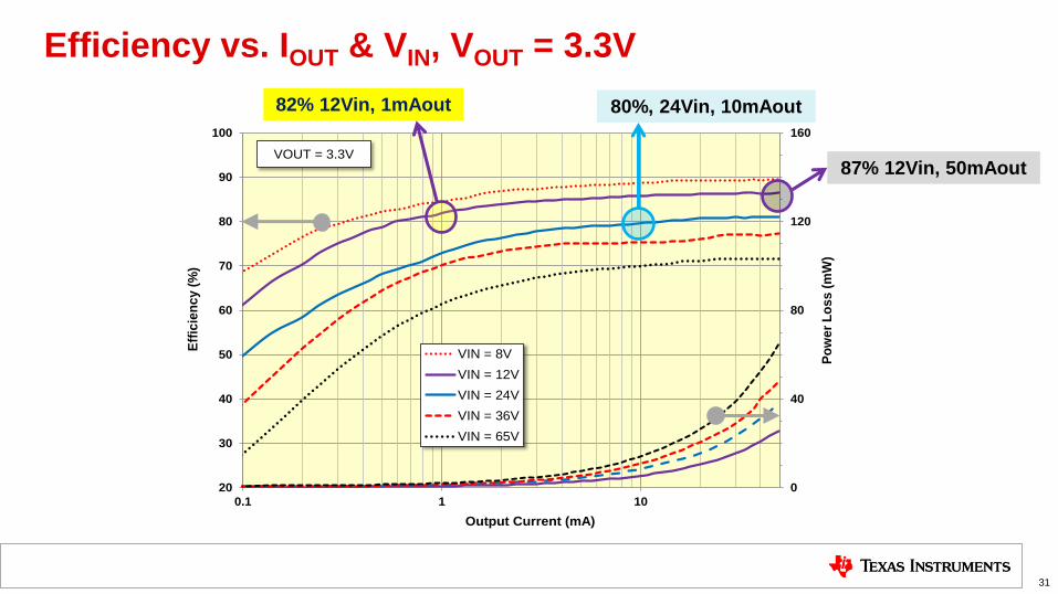
Efficiency vs. IOUT & VIN, VOUT = 3.3V
31
0
40
80
120
160
20
30
40
50
60
70
80
90
100
0.1 1 10
Po
we
r L
os
s (
mW
)
Eff
icie
nc
y (
%)
Output Current (mA)
VIN = 8V
VIN = 12V
VIN = 24V
VIN = 36V
VIN = 65V
VOUT = 3.3V
80%, 24Vin, 10mAout
87% 12Vin, 50mAout
82% 12Vin, 1mAout

Integrating several protocol into one IC
32
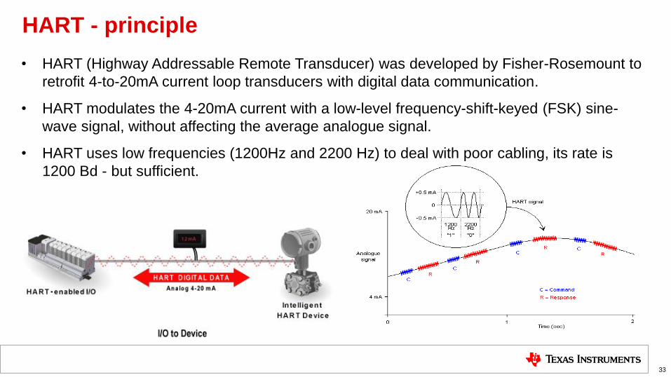
HART - principle
• HART (Highway Addressable Remote Transducer) was developed by Fisher-Rosemount to
retrofit 4-to-20mA current loop transducers with digital data communication.
• HART modulates the 4-20mA current with a low-level frequency-shift-keyed (FSK) sine-
wave signal, without affecting the average analogue signal.
• HART uses low frequencies (1200Hz and 2200 Hz) to deal with poor cabling, its rate is
1200 Bd - but sufficient.
33
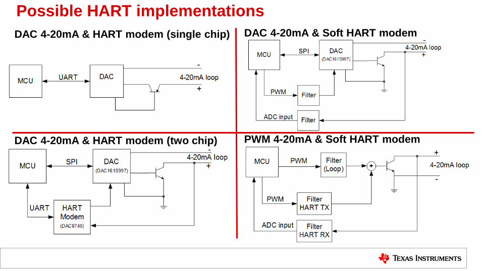
Possible HART implementations
PWM 4-20mA & Soft HART modem
DAC 4-20mA & Soft HART modem
DAC 4-20mA & HART modem (two chip)
DAC 4-20mA & HART modem (single chip)
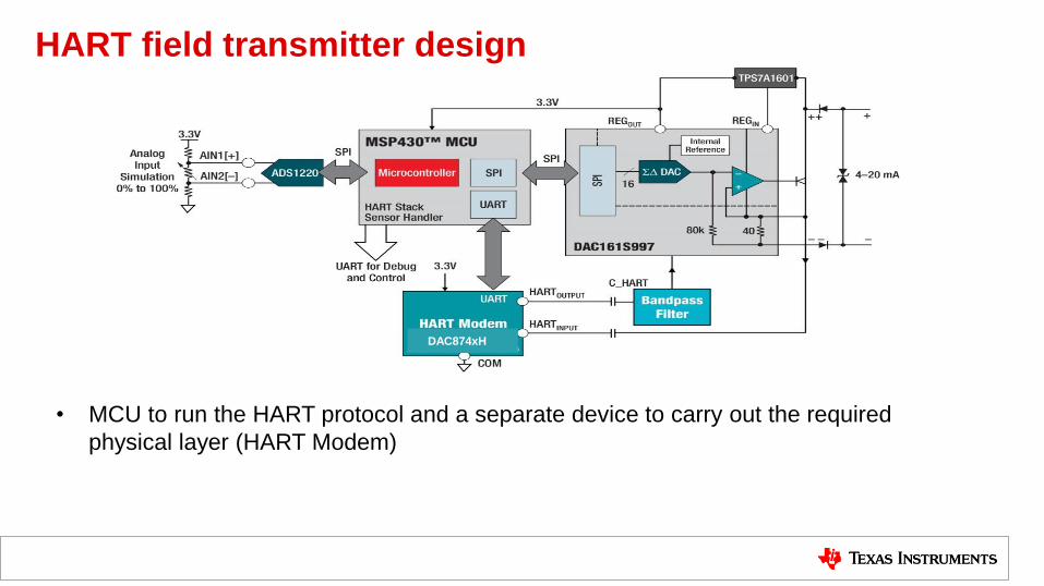
HART field transmitter design
• MCU to run the HART protocol and a separate device to carry out the required
physical layer (HART Modem)
DAC874xH
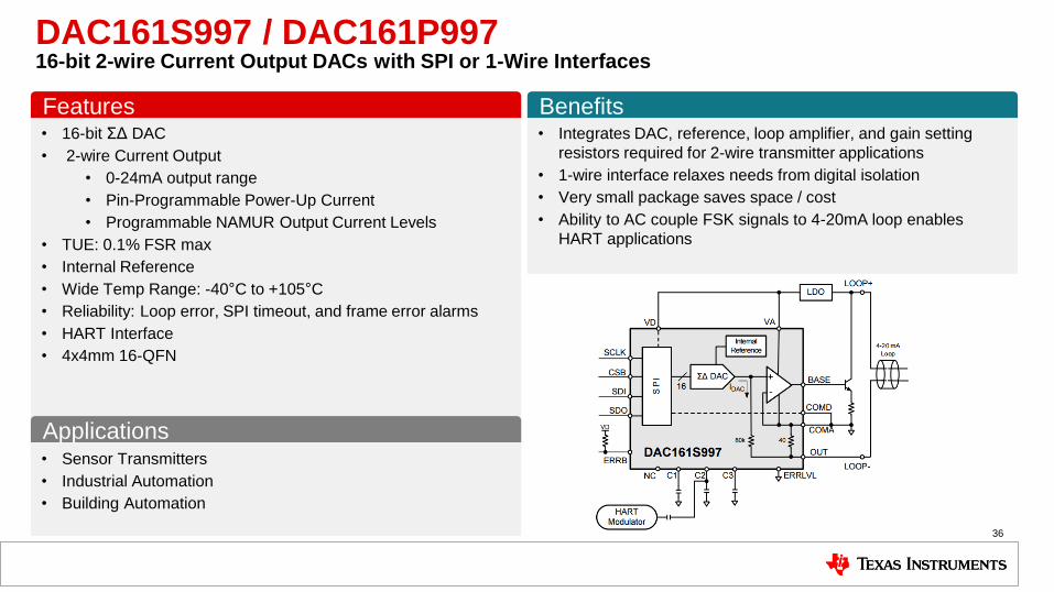
• 16-bit ΣΔ DAC
• 2-wire Current Output
• 0-24mA output range
• Pin-Programmable Power-Up Current
• Programmable NAMUR Output Current Levels
• TUE: 0.1% FSR max
• Internal Reference
• Wide Temp Range: -40°C to +105°C
• Reliability: Loop error, SPI timeout, and frame error alarms
• HART Interface
• 4x4mm 16-QFN
• Integrates DAC, reference, loop amplifier, and gain setting
resistors required for 2-wire transmitter applications
• 1-wire interface relaxes needs from digital isolation
• Very small package saves space / cost
• Ability to AC couple FSK signals to 4-20mA loop enables
HART applications
Features Benefits
DAC161S997 / DAC161P997 16-bit 2-wire Current Output DACs with SPI or 1-Wire Interfaces
36
• Sensor Transmitters
• Industrial Automation
• Building Automation
Applications
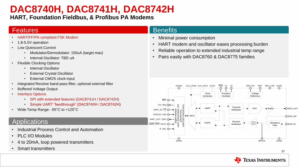
• HART/FF/PA compliant FSK Modem
• 1.8-5.5V operation
• Low Quiescent Current
• Modulator/Demodulator: 150uA (target max)
• Internal Oscillator: TBD uA
• Flexible Clocking Options
• Internal Oscillator
• External Crystal Oscillator
• External CMOS clock input
• Integrated Receive band-pass filter, optional external filter
• Buffered Voltage Output
• Interface Options
• SPI with extended features (DAC8741H / DAC8742H)
• Simple UART “feedthrough” (DAC8740H / DAC8742H)
• Wide Temp Range: -55°C to +125°C
• Minimal power consumption
• HART modem and oscillator eases processing burden
• Reliable operation to extended industrial temp range
• Pairs easily with DAC8760 & DAC8775 families
Features Benefits
DAC8740H, DAC8741H, DAC8742H HART, Foundation Fieldbus, & Profibus PA Modems
37
• Industrial Process Control and Automation
• PLC I/O Modules
• 4 to 20mA, loop powered transmitters
• Smart transmitters
Applications MUX
Dig
ita
l In
terf
ace
UA
RT
(D
AC
87
40H
), S
PI
(DA
C8
74
1H
),
UA
RT
/SP
I (D
AC
87
42
H)
HART
PA/FF
Transmit
Modulator
Receive
Modulator
DAC Buffer
Carrier
DetectBandpass
Filter
Clock
Generator
Precision
Oscillator
Voltage
Reference
CLK_CFG1 CLKOCLK_CFG0 XEN X2X1 REFREF_EN
MOD_OUT
MOD_INF
MOD_IN
IOVDD AVDD
DGND AGNDBPFEN
UART_RTS / SCLK
UART_OUT / SDO
DUPLEX / SDI
UART_IN / CS
CD / IRQ
RST
REG_CAP
IF_SEL
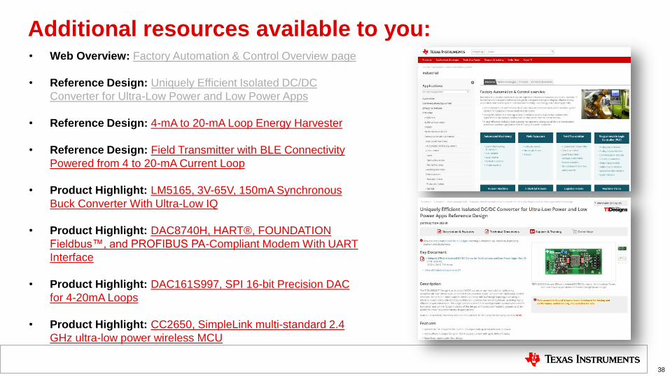
Additional resources available to you:
38
• Web Overview: Factory Automation & Control Overview page
• Reference Design: Uniquely Efficient Isolated DC/DC
Converter for Ultra-Low Power and Low Power Apps
• Reference Design: 4-mA to 20-mA Loop Energy Harvester
• Reference Design: Field Transmitter with BLE Connectivity
Powered from 4 to 20-mA Current Loop
• Product Highlight: LM5165, 3V-65V, 150mA Synchronous
Buck Converter With Ultra-Low IQ
• Product Highlight: DAC8740H, HART®, FOUNDATION
Fieldbus™, and PROFIBUS PA-Compliant Modem With UART
Interface
• Product Highlight: DAC161S997, SPI 16-bit Precision DAC
for 4-20mA Loops
• Product Highlight: CC2650, SimpleLink multi-standard 2.4
GHz ultra-low power wireless MCU

TI Information – Selective Disclosure