Embed Size (px)
Citation preview

Operating instructions
EN
Power source
Tetrix 230 DC Smart 2.0 puls TM Tetrix 230 AC/DC Smart 2.0 puls TM Tetrix 230 DC Comfort 2.0 puls TM Tetrix 230 AC/DC Comfort 2.0 puls TM
099-000239-EW501 Observe additional system documents! 18.05.2017

General instructions
WARNING
Read the operating instructions!
The operating instructions provide an introduction to the safe use of the products.
• Read and observe the operating instructions for all system components, especially the
safety instructions and warning notices!
• Observe the accident prevention regulations and any regional regulations!
• The operating instructions must be kept at the location where the machine is operated.
• Safety and warning labels on the machine indicate any possible risks.
Keep these labels clean and legible at all times.
• The machine has been constructed to state-of-the-art standards in line with any applicable
regulations and industrial standards. Only trained personnel may operate, service and
repair the machine.
• Technical changes due to further development in machine technology may lead to a
differing welding behaviour.
In the event of queries on installation, commissioning, operation or special conditions at the installation site, or on usage, please contact your sales partner or our customer service department on +49 2680 181-0.
A list of authorised sales partners can be found at www.ewm-group.com.
Liability relating to the operation of this equipment is restricted solely to the function of the
equipment. No other form of liability, regardless of type, shall be accepted. This exclusion of
liability shall be deemed accepted by the user on commissioning the equipment.
The manufacturer is unable to monitor whether or not these instructions or the conditions and
methods are observed during installation, operation, usage and maintenance of the equipment.
An incorrectly performed installation can result in material damage and injure persons as a
result. For this reason, we do not accept any responsibility or liability for losses, damages or
costs arising from incorrect installation, improper operation or incorrect usage and maintenance
or any actions connected to this in any way.
© EWM AG
Dr. Günter-Henle-Straße 8
56271 Mündersbach
Germany
The copyright to this document remains the property of the manufacturer.
Copying, including extracts, only permitted with written approval.
The content of this document has been prepared and reviewed with all reasonable care. The information
provided is subject to change; errors excepted.

Contents Notes on the use of these operating instructions
099-000239-EW501 18.05.2017 3
1 Contents
1 Contents .................................................................................................................................................. 3
2 For your safety ....................................................................................................................................... 5 2.1 Notes on the use of these operating instructions .......................................................................... 5 2.2 Explanation of icons ....................................................................................................................... 6 2.3 Part of the complete documentation .............................................................................................. 7 2.4 Safety instructions .......................................................................................................................... 7 2.5 Transport and installation ............................................................................................................ 10
3 Intended use ......................................................................................................................................... 12 3.1 Applications .................................................................................................................................. 12 3.2 Documents which also apply ....................................................................................................... 12
3.2.1 Warranty ....................................................................................................................... 12 3.2.2 Declaration of Conformity ............................................................................................. 12 3.2.3 Welding in environments with increased electrical hazards ......................................... 12 3.2.4 Service documents (spare parts and circuit diagrams) ................................................ 12 3.2.5 Calibration/Validation ................................................................................................... 12
4 Machine description – quick overview .............................................................................................. 13 4.1 Front view .................................................................................................................................... 13 4.2 Rear view ..................................................................................................................................... 14
5 Design and function ............................................................................................................................. 15 5.1 Transport and installation ............................................................................................................ 15
5.1.1 Ambient conditions ....................................................................................................... 15 5.1.1.1 In operation ................................................................................................... 15 5.1.1.2 Transport and storage ................................................................................... 15
5.1.2 Machine cooling ............................................................................................................ 15 5.1.3 Workpiece lead, general ............................................................................................... 16 5.1.4 Adjusting the length of the carrying strap ..................................................................... 16 5.1.5 Welding torch cooling system ....................................................................................... 17
5.1.5.1 Welding torch cooling unit connection .......................................................... 17 5.1.6 Notes on the installation of welding current leads ........................................................ 18
5.1.6.1 Stray welding currents................................................................................... 19 5.1.7 Mains connection .......................................................................................................... 19
5.1.7.1 Mains configuration ....................................................................................... 20 5.2 TIG welding .................................................................................................................................. 20
5.2.1 Welding torch and workpiece line connection .............................................................. 20 5.2.1.1 Connection variant, welding torch control cable ........................................... 21
5.2.2 Shielding gas supply (shielding gas cylinder for welding machine) ............................. 21 5.2.2.1 Connecting the shielding gas supply ............................................................ 22
5.3 MMA welding ............................................................................................................................... 23 5.3.1 Connecting the electrode holder and workpiece lead .................................................. 23
5.4 Remote control ............................................................................................................................. 24 5.4.1 RT1 19POL ................................................................................................................... 24 5.4.2 RTG1 19POL ................................................................................................................ 24 5.4.3 RTP1 19POL ................................................................................................................ 24 5.4.4 RTP2 19POL ................................................................................................................ 24 5.4.5 RTP3 spotArc 19POL ................................................................................................... 24 5.4.6 RTF1 19POL ................................................................................................................ 24
5.5 Voltage reducing device .............................................................................................................. 25 5.6 Interfaces for automation ............................................................................................................. 25
5.6.1 Remote control connection socket, 19-pole ................................................................. 25
6 Maintenance, care and disposal ......................................................................................................... 27 6.1 General ........................................................................................................................................ 27 6.2 Cleaning ....................................................................................................................................... 27
6.2.1 Dirt filter ........................................................................................................................ 27 6.3 Maintenance work, intervals ........................................................................................................ 28
6.3.1 Daily maintenance tasks .............................................................................................. 28 6.3.2 Monthly maintenance tasks .......................................................................................... 28

Contents Notes on the use of these operating instructions
4 099-000239-EW501 18.05.2017
6.3.3 Annual test (inspection and testing during operation) .................................................. 28 6.4 Disposing of equipment ................................................................................................................ 29 6.5 Meeting the requirements of RoHS .............................................................................................. 29
7 Rectifying faults.................................................................................................................................... 30 7.1 Checklist for rectifying faults ........................................................................................................ 30 7.2 Vent coolant circuit ....................................................................................................................... 31
8 Technical data....................................................................................................................................... 32 8.1 Tetrix 230 ..................................................................................................................................... 32 8.2 Tetrix 230 AC/DC ......................................................................................................................... 33
9 Accessories .......................................................................................................................................... 34 9.1 Remote controls and accessories ................................................................................................ 34 9.2 Welding torch cooling system ...................................................................................................... 34 9.3 Transport systems ........................................................................................................................ 34 9.4 General accessories .................................................................................................................... 34 9.5 Options ......................................................................................................................................... 34
10 Appendix A ............................................................................................................................................ 35 10.1 Overview of EWM branches......................................................................................................... 35

For your safety Notes on the use of these operating instructions
099-000239-EW501 18.05.2017 5
2 For your safety
2.1 Notes on the use of these operating instructions
DANGER Working or operating procedures which must be closely observed to prevent imminent
serious and even fatal injuries.
• Safety notes include the "DANGER" keyword in the heading with a general warning symbol.
• The hazard is also highlighted using a symbol on the edge of the page.
WARNING Working or operating procedures which must be closely observed to prevent serious
and even fatal injuries.
• Safety notes include the "WARNING" keyword in the heading with a general warning
symbol.
• The hazard is also highlighted using a symbol in the page margin.
CAUTION Working or operating procedures which must be closely observed to prevent possible
minor personal injury.
• The safety information includes the "CAUTION" keyword in its heading with a general
warning symbol.
• The risk is explained using a symbol on the edge of the page.
Special technical points which users must observe.
Instructions and lists detailing step-by-step actions for given situations can be recognised via bullet
points, e.g.:
• Insert the welding current lead socket into the relevant socket and lock.

For your safety Explanation of icons
6 099-000239-EW501 18.05.2017
2.2 Explanation of icons
Symbol Description Symbol Description
Indicates technical aspects which the
user must observe.
Activate and release/tap/tip
Switch off machine
Release
Switch on machine
Press and keep pressed
Switch
Wrong
Turn
Correct
Numerical value – adjustable
Menu entry
Signal light lights up in green
Navigating the menu
Signal light flashes green
Exit menu
Signal light lights up in red
Time representation (e.g.: wait
4 s/activate)
Signal light flashes red
Interruption in the menu display (other
setting options possible)
Tool not required/do not use
Tool required/use

For your safety Part of the complete documentation
099-000239-EW501 18.05.2017 7
2.3 Part of the complete documentation
These operating instructions are part of the complete documentation and valid only in combination with all other parts of these instructions! Read and observe the operating instructions for all system components, especially the safety instructions!
The illustration shows a general example of a welding system.
Figure 2-1
Item Documentation
A.1 Options conversion instructions
A.2 Power source
A.3 Cooling unit, voltage converter, tool box etc.
A.4 Transport cart
A.5 Welding torch
A.6 Remote control
A.7 Control
A Complete documentation
2.4 Safety instructions
WARNING
Risk of accidents due to non-compliance with the safety instructions!
Non-compliance with the safety instructions can be fatal!
• Carefully read the safety instructions in this manual!
• Observe the accident prevention regulations and any regional regulations!
• Inform persons in the working area that they must comply with the regulations!
Risk of injury from electrical voltage!
Voltages can cause potentially fatal electric shocks and burns on contact. Even low
voltages can cause a shock and lead to accidents.
• Never touch live components such as welding current sockets or stick, tungsten or wire
electrodes!
• Always place torches and electrode holders on an insulated surface!
• Wear the full personal protective equipment (depending on the application)!
• The machine may only be opened by qualified personnel!
For your safety Safety instructions
8 099-000239-EW501 18.05.2017
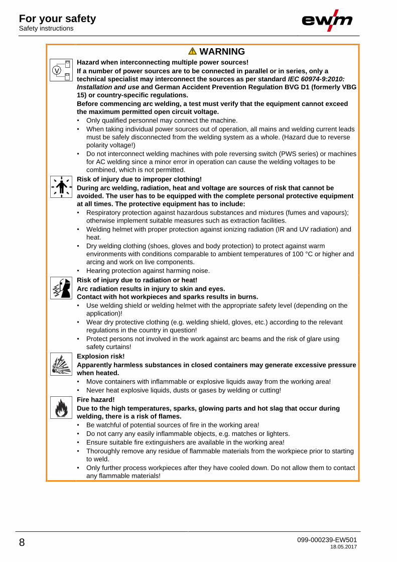
WARNING
Hazard when interconnecting multiple power sources!
If a number of power sources are to be connected in parallel or in series, only a
technical specialist may interconnect the sources as per standard IEC 60974-9:2010:
Installation and use and German Accident Prevention Regulation BVG D1 (formerly VBG
15) or country-specific regulations.
Before commencing arc welding, a test must verify that the equipment cannot exceed
the maximum permitted open circuit voltage.
• Only qualified personnel may connect the machine.
• When taking individual power sources out of operation, all mains and welding current leads
must be safely disconnected from the welding system as a whole. (Hazard due to reverse
polarity voltage!)
• Do not interconnect welding machines with pole reversing switch (PWS series) or machines
for AC welding since a minor error in operation can cause the welding voltages to be
combined, which is not permitted.
Risk of injury due to improper clothing!
During arc welding, radiation, heat and voltage are sources of risk that cannot be
avoided. The user has to be equipped with the complete personal protective equipment
at all times. The protective equipment has to include:
• Respiratory protection against hazardous substances and mixtures (fumes and vapours);
otherwise implement suitable measures such as extraction facilities.
• Welding helmet with proper protection against ionizing radiation (IR and UV radiation) and
heat.
• Dry welding clothing (shoes, gloves and body protection) to protect against warm
environments with conditions comparable to ambient temperatures of 100 °C or higher and
arcing and work on live components.
• Hearing protection against harming noise.
Risk of injury due to radiation or heat!
Arc radiation results in injury to skin and eyes.
Contact with hot workpieces and sparks results in burns.
• Use welding shield or welding helmet with the appropriate safety level (depending on the
application)!
• Wear dry protective clothing (e.g. welding shield, gloves, etc.) according to the relevant
regulations in the country in question!
• Protect persons not involved in the work against arc beams and the risk of glare using
safety curtains!
Explosion risk!
Apparently harmless substances in closed containers may generate excessive pressure
when heated.
• Move containers with inflammable or explosive liquids away from the working area!
• Never heat explosive liquids, dusts or gases by welding or cutting!
Fire hazard!
Due to the high temperatures, sparks, glowing parts and hot slag that occur during
welding, there is a risk of flames.
• Be watchful of potential sources of fire in the working area!
• Do not carry any easily inflammable objects, e.g. matches or lighters.
• Ensure suitable fire extinguishers are available in the working area!
• Thoroughly remove any residue of flammable materials from the workpiece prior to starting
to weld.
• Only further process workpieces after they have cooled down. Do not allow them to contact
any flammable materials!

For your safety Safety instructions
099-000239-EW501 18.05.2017 9
CAUTION
Smoke and gases!
Smoke and gases can lead to breathing difficulties and poisoning. In addition, solvent
vapour (chlorinated hydrocarbon) may be converted into poisonous phosgene due to
the ultraviolet radiation of the arc!
• Ensure that there is sufficient fresh air!
• Keep solvent vapour away from the arc beam field!
• Wear suitable breathing apparatus if appropriate!
Noise exposure!
Noise exceeding 70 dBA can cause permanent hearing damage!
• Wear suitable ear protection!
• Persons located within the working area must wear suitable ear protection!
Obligations of the operator!
The respective national directives and laws must be complied with when operating the machine!
• Implementation of national legislation relating to framework directive 89/391/EEC on the introduction of measures to encourage improvements in the safety and health of workers at work and associated individual guidelines.
• In particular, directive 89/655/EEC concerning the minimum safety and health requirements for the use of work equipment by workers at work.
• The regulations applicable to occupational safety and accident prevention in the country concerned.
• Setting up and operating the machine as per IEC 60974.-9.
• Brief the user on safety-conscious work practices on a regular basis.
• Regularly inspect the machine as per IEC 60974.-4.
The manufacturer's warranty becomes void if non-genuine parts are used!
• Only use system components and options (power sources, welding torches, electrode holders, remote controls, spare parts and replacement parts, etc.) from our range of products!
• Only insert and lock accessory components into the relevant connection socket when the machine is switched off.
Requirements for connection to the public mains network
High-performance machines can influence the mains quality by taking current from the mains network. For some types of machines, connection restrictions or requirements relating to the maximum possible line impedance or the necessary minimum supply capacity at the interface with the public network (Point of Common Coupling, PCC) can therefore apply. In this respect, attention is also drawn to the machines' technical data. In this case, it is the responsibility of the operator, where necessary in consultation with the mains network operator, to ensure that the machine can be connected.
CAUTION
Electromagnetic fields!
The power source may cause electrical or electromagnetic fields to be produced which
could affect the correct functioning of electronic equipment such as IT or CNC devices,
telecommunication lines, power cables, signal lines and pacemakers.
• Observe the maintenance instructions > see 6.3 chapter!
• Unwind welding leads completely!
• Shield devices or equipment sensitive to radiation accordingly!
• The correct functioning of pacemakers may be affected (obtain advice from a doctor if
necessary).

For your safety Transport and installation
10 099-000239-EW501 18.05.2017
CAUTION
According to IEC 60974-10, welding machines are divided into two classes of
electromagnetic compatibility (the EMC class can be found in the Technical
data) > see 8 chapter:
Class A machines are not intended for use in residential areas where the power supply comes
from the low-voltage public mains network. When ensuring the electromagnetic compatibility of
class A machines, difficulties can arise in these areas due to interference not only in the supply
lines but also in the form of radiated interference.
Class B machines fulfil the EMC requirements in industrial as well as residential areas,
including residential areas connected to the low-voltage public mains network.
Setting up and operating
When operating arc welding systems, in some cases, electro-magnetic interference can occur
although all of the welding machines comply with the emission limits specified in the standard.
The user is responsible for any interference caused by welding.
In order to evaluate any possible problems with electromagnetic compatibility in the
surrounding area, the user must consider the following: (see also EN 60974-10 Appendix A)
• Mains, control, signal and telecommunication lines
• Radios and televisions
• Computers and other control systems
• Safety equipment
• The health of neighbouring persons, especially if they have a pacemaker or wear a hearing
aid
• Calibration and measuring equipment
• The immunity to interference of other equipment in the surrounding area
• The time of day at which the welding work must be carried out
Recommendations for reducing interference emission
• Mains connection, e.g. additional mains filter or shielding with a metal tube
• Maintenance of the arc welding system
• Welding leads should be as short as possible and run closely together along the ground
• Potential equalization
• Earthing of the workpiece. In cases where it is not possible to earth the workpiece directly,
it should be connected by means of suitable capacitors.
• Shielding from other equipment in the surrounding area or the entire welding system
2.5 Transport and installation
WARNING
Risk of injury due to improper handling of shielding gas cylinders!
Improper handling and insufficient securing of shielding gas cylinders can cause
serious injuries!
• Observe the instructions from the gas manufacturer and any relevant regulations
concerning the use of compressed air!
• Do not attach any element to the shielding gas cylinder valve!
• Prevent the shielding gas cylinder from heating up.
CAUTION
Risk of accidents due to supply lines!
During transport, attached supply lines (mains leads, control cables, etc.) can cause
risks, e.g. by causing connected machines to tip over and injure persons!
• Disconnect all supply lines before transport!
Risk of tipping!
There is a risk of the machine tipping over and injuring persons or being damaged itself
during movement and set up. Tilt resistance is guaranteed up to an angle of 10°
(according to IEC 60974-1).
• Set up and transport the machine on level, solid ground.
• Secure add-on parts using suitable equipment.

For your safety Transport and installation
099-000239-EW501 18.05.2017 11
CAUTION
Risk of accidents due to incorrectly installed leads!
Incorrectly installed leads (mains, control and welding leads or intermediate hose
packages ) can present a tripping hazard.
• Lay the supply lines flat on the floor (avoid loops).
• Avoid laying the leads on passage ways.
The units are designed for operation in an upright position!
Operation in non-permissible positions can cause equipment damage.
• Only transport and operate in an upright position!
Accessory components and the power source itself can be damaged by incorrect connection!
• Only insert and lock accessory components into the relevant connection socket when the machine is switched off.
• Comprehensive descriptions can be found in the operating instructions for the relevant accessory components.
• Accessory components are detected automatically after the power source is switched on.
Protective dust caps protect the connection sockets and therefore the machine against dirt and damage.
• The protective dust cap must be fitted if there is no accessory component being operated on that connection.
• The cap must be replaced if faulty or if lost!

Intended use Applications
12 099-000239-EW501 18.05.2017
3 Intended use
WARNING
Hazards due to improper usage!
The machine has been constructed to the state of the art and any regulations and
standards applicable for use in industry and trade. It may only be used for the welding
procedures indicated at the rating plate. Hazards may arise for persons, animals and
material objects if the equipment is not used correctly. No liability is accepted for any
damages arising from improper usage!
• The equipment must only be used in line with its designated purpose and by trained or
expert personnel!
• Do not improperly modify or convert the equipment!
3.1 Applications Arc welding machine for TIG DC and AC welding with lift arc (touch starting) or HF ignition (contactless)
and MMA welding as secondary process. It may be possible to expand the functionality by using
accessories (see the documentation in the relevant chapter).
3.2 Documents which also apply
3.2.1 Warranty
For more information refer to the "Warranty registration" brochure supplied and our information regarding warranty, maintenance and testing at www.ewm-group.com!
3.2.2 Declaration of Conformity
The labelled machine complies with the following EC directives in terms of its design and
construction:
• Low Voltage Directive (LVD)
• Electromagnetic Compatibility Directive (EMC)
• Restriction of Hazardous Substance (RoHS)
In case of unauthorised changes, improper repairs, non-compliance with specified deadlines for "Arc
Welding Equipment – Inspection and Testing during Operation", and/or prohibited modifications which
have not been explicitly authorised by EWM, this declaration shall be voided. An original document of the
specific declaration of conformity is included with every product.
3.2.3 Welding in environments with increased electrical hazards
In compliance with IEC / DIN EN 60974, VDE 0544 the machines can be used in
environments with an increased electrical hazard.
3.2.4 Service documents (spare parts and circuit diagrams)
WARNING
Do not carry out any unauthorised repairs or modifications!
To avoid injury and equipment damage, the unit must only be repaired or modified by
specialist, skilled persons!
The warranty becomes null and void in the event of unauthorised interference.
• Appoint only skilled persons for repair work (trained service personnel)!
Original copies of the circuit diagrams are enclosed with the unit.
Spare parts can be obtained from the relevant authorised dealer.
3.2.5 Calibration/Validation
We hereby confirm that this machine has been tested using calibrated measuring equipment, as
stipulated in IEC/EN 60974, ISO/EN 17662, EN 50504, and complies with the admissible tolerances.
Recommended calibration interval: 12 months
Machine description – quick overview Front view
099-000239-EW501 18.05.2017 13
4 Machine description – quick overview
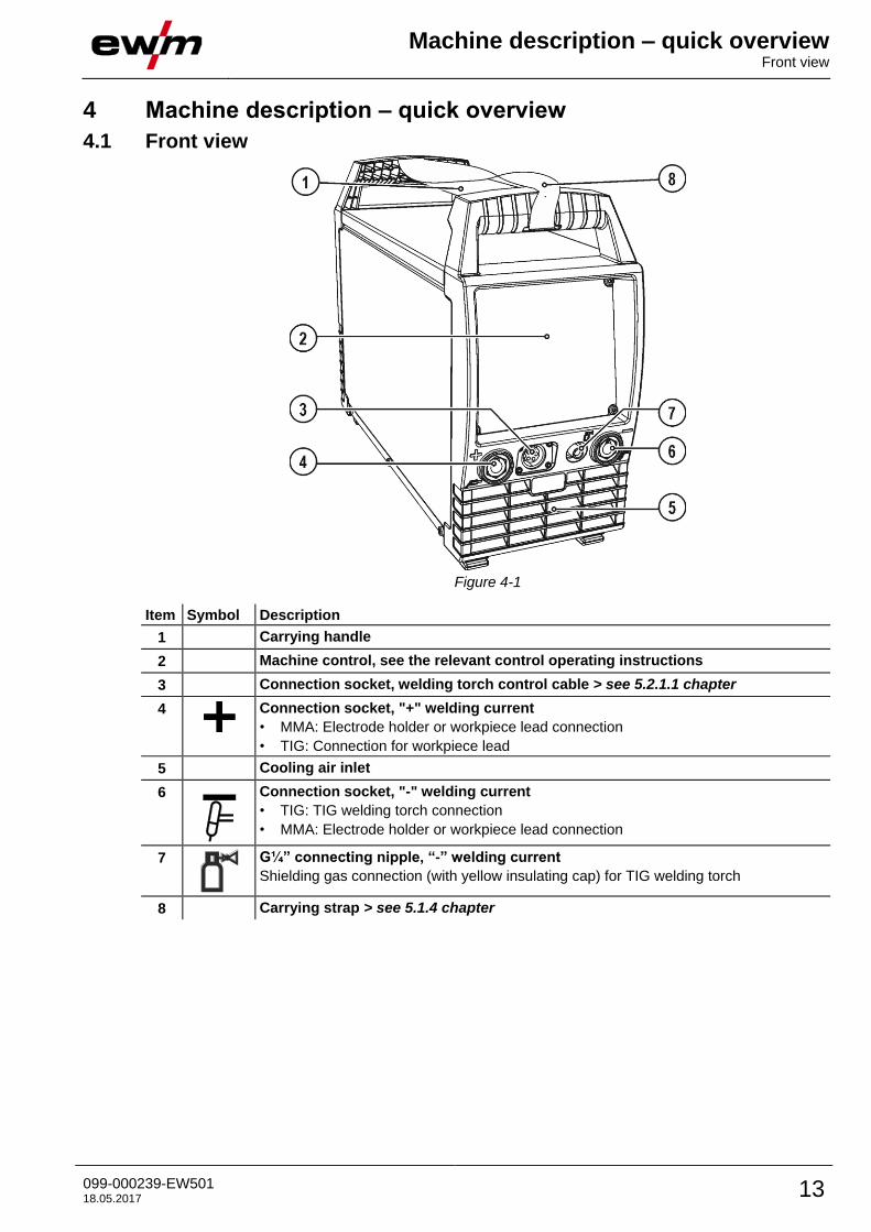
4.1 Front view
Figure 4-1
Item Symbol Description 0
1 Carrying handle
2 Machine control, see the relevant control operating instructions
3 Connection socket, welding torch control cable > see 5.2.1.1 chapter
4
Connection socket, "+" welding current
• MMA: Electrode holder or workpiece lead connection
• TIG: Connection for workpiece lead
5 Cooling air inlet
6
Connection socket, "-" welding current
• TIG: TIG welding torch connection
• MMA: Electrode holder or workpiece lead connection
7
G¼” connecting nipple, “-” welding current
Shielding gas connection (with yellow insulating cap) for TIG welding torch
8 Carrying strap > see 5.1.4 chapter

Machine description – quick overview Rear view
14 099-000239-EW501 18.05.2017
4.2 Rear view
Figure 4-2
Item Symbol Description 0
1
Main switch, machine on/off
2 Cooling air outlet
3 Machine feet
4
Connection socket, 19-pole
Remote control connection
5
8-pole connection socket
Cooling unit control lead
6
G¼” connecting nipple
Shielding gas connection on the pressure regulator.
7
4-pole connection socket
Cooling unit voltage supply
8 Mains connection cable > see 5.1.7 chapter

Design and function Transport and installation
099-000239-EW501 18.05.2017 15
5 Design and function
WARNING
Risk of injury from electric shock!
Contact with live parts, e.g. welding current sockets, is potentially fatal!
• Follow safety instructions on the opening pages of the operating instructions.
• Commissioning may only be carried out by persons who have the relevant expertise of
working with arc welding machines!
• Connection and welding leads (e.g. electrode holder, welding torch, workpiece lead,
interfaces) may only be connected when the machine is switched off!
5.1 Transport and installation
WARNING
Risk of accident due to improper transport of machines that must not be lifted!
Do not lift or suspend the machine! The machine can drop and cause injuries! The
handles, straps or brackets are suitable for transport by hand only!
• The machine must not be suspended or lifted using a crane.
Read and observe the documentation to all system and accessory components!
5.1.1 Ambient conditions
T he machine must not be operated in the open air and must only be set up and operated on a suitable, stable and level base!
• The operator must ensure that the ground is non-slip and level, and provide sufficient lighting for the place of work.
• Safe operation of the machine must be guaranteed at all times.
Unusually high quantities of dust, acid, corrosive gases or substances may damage the equipment.
• Avoid high volumes of smoke, vapour, oil vapour and grinding dust!
• Avoid ambient air containing salt (sea air)!
5.1.1.1 In operation
Temperature range of the ambient air:
• -25 °C to +40 °C
Relative air humidity:
• Up to 50% at 40 °C
• Up to 90% at 20 °C
5.1.1.2 Transport and storage
Storage in an enclosed space, temperature range of the ambient air:
• -30 °C to +70 °C
Relative air humidity
• Up to 90% at 20 °C
5.1.2 Machine cooling
Insufficient ventilation results in a reduction in performance and equipment damage.
• Observe the ambient conditions!
• Keep the cooling air inlet and outlet clear!
• Observe the minimum distance of 0.5 m from obstacles!

Design and function Transport and installation
16 099-000239-EW501 18.05.2017
5.1.3 Workpiece lead, general
CAUTION
Risk of burning due to incorrect welding current connection!
If the welding current plugs (machine connections) are not locked or if the workpiece
connection is contaminated (paint, corrosion), these connections and leads can heat up
and cause burns when touched!
• Check welding current connections on a daily basis and lock by turning to the right when
necessary.
• Clean workpiece connection thoroughly and secure properly. Do not use structural parts of
the workpiece as welding current return lead!
5.1.4 Adjusting the length of the carrying strap
To demonstrate adjustment, lengthening the strap is shown in the figure. To shorten, the strap's loops must be inched in the opposite direction.
Figure 5-1

Design and function Transport and installation
099-000239-EW501 18.05.2017 17
5.1.5 Welding torch cooling system
5.1.5.1 Welding torch cooling unit connection
Read and observe the documentation to all system and accessory components!
Figure 5-2
Item Symbol Description 0
1
8-pole connection socket
Cooling unit control lead
2
4-pole connection socket
Cooling unit voltage supply
3
Cooling module
• Insert and lock the 8-pole control lead plug on the cooling unit into the 8-pole connection socket on the
welding machine.
• Insert and lock the 4-pole supply plug on the cooling unit into the 4-pole connection socket on the
welding machine.

Design and function Transport and installation
18 099-000239-EW501 18.05.2017
5.1.6 Notes on the installation of welding current leads
Incorrectly installed welding current leads can cause faults in the arc (flickering).
Lay the workpiece lead and hose package of power sources without HF igniter (MIG/MAG) for as long and as close as possible in parallel.
Lay the workpiece lead and hose package of power sources with HF igniter (TIG) for as long as possible in parallel with a distance of 20 cm to avoid HF sparkover.
Always keep a distance of at least 20 cm to leads of other power sources to avoid interferences
Always keep leads as short as possible! For optimum welding results max. 30 m (welding lead + intermediate hose package + torch lead).
Figure 5-3
Use an individual welding lead to the workpiece for each welding machine!
Figure 5-4
Fully unroll welding current leads, torch hose packages and intermediate hose packages. Avoid loops!
Always keep leads as short as possible!
Lay any excess cable lengths in meanders.
Figure 5-5

Design and function Transport and installation
099-000239-EW501 18.05.2017 19
5.1.6.1 Stray welding currents
WARNING
Risk of injury due to stray welding currents!
Stray welding currents can destroy protective earth conductors, damage machines and
electronic devices and cause overheating of components, leading to fire.
• Check that all welding current connections are firmly secured and electrical connections are
in perfect condition.
• Set up, attach or suspend all conductive power source components such as casing,
transport vehicles and crane frames so they are insulated.
• Do not place any other electronic devices such as drills or angle grinders on the power
source, transport vehicle or crane frames unless they are insulated.
• Always put welding torches and electrode holders on an insulated surface when they are
not in use.
Figure 5-6
5.1.7 Mains connection
DANGER
Hazards caused by improper mains connection!
An improper mains connection can cause injuries or damage property!
• Only operate machine using a socket that has correctly fitted protective earth.
• The mains voltage indicated on the rating plate must match the supply voltage.
• If a new mains plug must be fitted, only an electrician may do so as per the relevant
national legislation or regulations.
• Mains plug, socket and lead must be checked by an electrician on a regular basis.
• When operating the generator, always ensure it is earthed as stipulated in the operating
instructions. The network created must be suitable for operating machines according to
protection class I.

Design and function TIG welding
20 099-000239-EW501 18.05.2017
5.1.7.1 Mains configuration
The machine may only be connected to a one-phase system with two conductors and an earthed neutral conductor.
Figure 5-7
Legend
Item Designation Colour code
L Outer conductor brown
N Neutral conductor blue
PE Protective conductor green-yellow
• Insert mains plug of the switched-off machine into the appropriate socket.
5.2 TIG welding
5.2.1 Welding torch and workpiece line connection
Prepare welding torch according to the welding task in hand (see operating instructions for the torch).
Figure 5-8
Item Symbol Description 0
1
Welding torch
2 Welding torch hose package
3 Connection socket, "-" welding current
Welding current lead connection for TIG welding torch
4
G¼" connecting nipple
TIG welding torch shielding gas connection
5 Connection socket, welding torch control cable > see 5.2.1.1 chapter
6
Workpiece
7
Connection socket for "+" welding current
Workpiece lead connection

Design and function TIG welding
099-000239-EW501 18.05.2017 21
• Insert the welding current plug on the welding torch into the welding current connection socket and
lock by turning to the right.
• Remove yellow protective cap on G¼ connecting nipple.
• Screw welding torch shielding gas connection tightly onto the G¼" connection nipple.
• Plug the welding torch control cable plug into the welding torch control cable connection socket and
secure.
• Insert the cable plug on the work piece lead into the "+" welding current connection socket and lock by
turning to the right.
If fitted:
• Lock connecting nipples of the cooling water tubes into the corresponding quick connect couplings:
Return line red to quick connect coupling, red (coolant return) and
supply line blue to quick connect coupling, blue (coolant supply).
Read and observe the documentation to all system and accessory components!
5.2.1.1 Connection variant, welding torch control cable
TIG welding machines are equipped ex works with a dedicated connection socket for the welding torch
control cable (5- or 8-pole). As mobile machines offer more free space, they may even feature two control
cable connection sockets. The functionality increases with the number of poles. One of these connection
sockets may be converted or retrofitted > see 9 chapter.
TIG standard torch TIG up/down or potentiometer torch
Figure 5-9
5.2.2 Shielding gas supply (shielding gas cylinder for welding machine)
WARNING
Risk of injury due to improper handling of shielding gas cylinders!
Improper handling and insufficient securing of shielding gas cylinders
can cause serious injuries!
• Place shielding gas cylinder into the designated holder and secure with
fastening elements (chain/belt)!
• Attach the fastening elements within the upper half of the shielding gas
cylinder!
• The fastening elements must tightly enclose the shielding gas cylinder!
An unhindered shielding gas supply from the shielding gas cylinder to the welding torch is a fundamental requirement for optimum welding results. In addition, a blocked shielding gas supply may result in the welding torch being destroyed.
• Always re-fit the yellow protective cap when not using the shielding gas connection.
• All shielding gas connections must be gas tight.

Design and function TIG welding
22 099-000239-EW501 18.05.2017
5.2.2.1 Connecting the shielding gas supply
• Place the shielding gas cylinder into the relevant cylinder bracket.
• Secure the shielding gas cylinder using a securing chain.
Figure 5-10
Item Symbol Description 0
1 Pressure regulator
2 Shielding gas cylinder
3 Output side of the pressure regulator
4 Cylinder valve
• Before connecting the pressure regulator to the gas cylinder, open the cylinder valve briefly to blow
out any dirt.
• Tighten the pressure regulator screw connection on the gas bottle valve to be gas-tight.
• Screw gas hose connection crown nut onto the output side of the pressure regulator.
Figure 5-11
Item Symbol Description 0
1
Connecting nipple G¼, shielding gas connection
• Connect crown nut of the shielding gas line to the G¼“ connecting nipple.

Design and function MMA welding
099-000239-EW501 18.05.2017 23
5.3 MMA welding
5.3.1 Connecting the electrode holder and workpiece lead
CAUTION
Risk of crushing and burns!
When changing stick electrodes there is a risk of crushing and burns!
• Wear appropriate and dry protective gloves.
• Use an insulated pair of tongs to remove the used stick electrode or to move welded
workpieces.
Shielding gas connection!
During MMA welding open circuit voltage is applied at the shielding gas connection
(G¼" connecting nipple).
• Place yellow insulating cap on the G¼" connection nipple (protects against electrical
voltage and dirt).
Figure 5-12
Item Symbol Description 0
1
Electrode holder
2 Connection socket, “-” welding current
Workpiece lead or electrode holder connection
3
Workpiece
4
Connection socket for "+" welding current
Electrode holder or workpiece lead connection
5
Connecting nipple G¼, shielding gas connection
Polarity depends on the instructions from the electrode manufacturer given on the electrode packaging.
• Insert cable plug of the electrode holder into either the "+" or "-" welding current connection socket and
lock by turning to the right.
• Insert cable plug of the workpiece lead into either the "+" or "-" welding current connection socket and
lock by turning to the right.
• Fit yellow protective cap onto G¼" connecting nipple.

Design and function Remote control
24 099-000239-EW501 18.05.2017
5.4 Remote control
The remote controls are operated on the 19-pole remote control connection socket (analogue).
5.4.1 RT1 19POL
Functions
• Infinitely adjustable welding current (0% to 100%) depending on the preselected
main current on the welding machine.
5.4.2 RTG1 19POL
Functions
• Infinite setting of the welding current (0% to 100%) depending on the main current
preselected at the welding machine
5.4.3 RTP1 19POL
Functions
• TIG/MMA
• Infinitely adjustable welding current (0% to 100%) depending on the preselected
main current on the welding machine.
• Pulse/spot/normal
• Pulse, spot and break times are infinitely adjustable.
5.4.4 RTP2 19POL
Functions
• TIG/MMA.
• Infinitely adjustable welding current (0% to 100%) depending on the preselected
main current on the welding machine.
• Pulse/spot/normal
• Frequency and spot times infinitely adjustable.
• Coarse adjustment of the cycle frequency.
• Pulse/pause ratio (balance) adjustable from 10% to 90%.
5.4.5 RTP3 spotArc 19POL
Functions
• TIG / MMA.
• Infinitely adjustable welding current (0% to 100%) depending on the preselected
main current on the welding machine.
• Pulse / SpotArc spots / normal
• Frequency and spot time infinitely adjustable.
• Coarse adjustment of the pulse frequency.
• Pulse/pause ratio (balance) adjustable from 10% to 90%.
5.4.6 RTF1 19POL
Functions
• Infinitely adjustable welding current (0% to 100%) depending on the preselected
main current on the welding machine.
• Start/stop welding operation (TIG)
ActivArc welding is not possible in combination with the foot-operated remote control.
Design and function Voltage reducing device
099-000239-EW501 18.05.2017 25
5.5 Voltage reducing device Only machine variants with the (VRD/AUS/RU) code are equipped with a voltage reduction device (VRD).
The VRD is used for increased safety, especially in hazardous environments such as shipbuilding, pipe
construction or mining.
A VRD is mandatory in some countries and required by many on-site safety instructions for power
sources.
The VRD signal light is illuminated when the voltage reduction device is operating without fault and the
output voltage is reduced to a value specified in the relevant standard (see technical data).
5.6 Interfaces for automation
Damage to the machine due to improper connection!
Unsuitable control leads or incorrect connection of input and output signals can cause damage to the machine.
• Only use shielded control leads!
• If the machine is to be operated with control voltages connection via suitable isolation amplifiers is required!
• To control the main or secondary current via control voltages, the relevant inputs must be enabled (see specification for activation of control voltage).
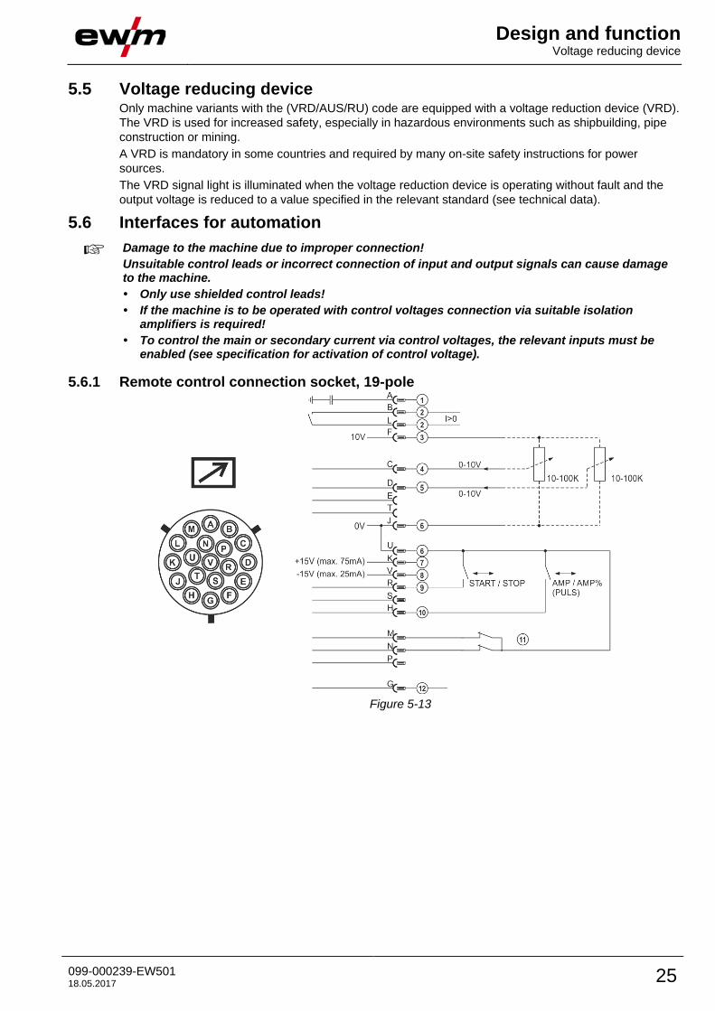
5.6.1 Remote control connection socket, 19-pole
Figure 5-13

Design and function Interfaces for automation
26 099-000239-EW501 18.05.2017
Item Pin Signal shape Designation
1 A Output Connection for cable screen (PE)
2 B/L Output Current flowing signal I>0, galvanically isolated (max. +- 15V/100mA)
3 F Output Reference voltage for potentiometer 10V (max. 10mA)
4 C Input Control voltage specification for main current, 0–10V (0V = Imin/10V =
Imax)
5 D Input Control voltage specification for secondary current, 0–10V (0V =
Imin/10V = Imax)
6 J/U Output Reference potential 0V
7 K Output Power supply +15V, max. 75mA
8 V Output Power supply -15V, max. 25mA
9 R Input Start/Stop welding current
10 H Input Switching between main and secondary welding currents (pulses)
11 M/N Input Activation of control voltage specification
Signals M and N must be set to reference potential 0V to activate the
external control voltage specification for main and secondary current.

Maintenance, care and disposal General
099-000239-EW501 18.05.2017 27
6 Maintenance, care and disposal
6.1 General
DANGER
Risk of injury due to electrical voltage after switching off!
Working on an open machine can lead to fatal injuries!
Capacitors are loaded with electrical voltage during operation. Voltage remains present
for up to four minutes after the mains plug is removed.
1. Switch off machine.
2. Remove the mains plug.
3. Wait for at last 4 minutes until the capacitors have discharged!
WARNING
Incorrect maintenance, testing and repair!
Maintenance, testing and repair of the machine may only be carried out by skilled and
qualified personnel. A qualified person is one who, because of his or her training,
knowledge and experience, is able to recognise the dangers that can occur while testing
welding power sources as well as possible subsequent damage, and who is able to
implement the required safety procedures.
Observe the maintenance instructions > see 6.3 chapter.
• In the event that the provisions of one of the below-stated tests are not met, the machine
must not be operated again until it has been repaired and a new test has been carried out!
Repair and maintenance work may only be performed by qualified authorised personnel; otherwise the
right to claim under warranty is void. In all service matters, always consult the dealer who supplied the
machine. Return deliveries of defective equipment subject to warranty may only be made through your
dealer. When replacing parts, use only original spare parts. When ordering spare parts, please quote the
machine type, serial number and item number of the machine, as well as the type designation and item
number of the spare part.
Under the specified ambient conditions and normal working conditions this machine is essentially
maintenance-free and requires just a minimum of care.
Contamination of the machine may impair service life and duty cycle. The cleaning intervals depend on
the ambient conditions and the resulting contamination of the machine. The minimum interval is every six
months.
6.2 Cleaning • Clean the outer surfaces with a moist cloth (no aggressive cleaning agents).
• Purge the machine venting channel and cooling fins (if present) with oil- and water-free compressed
air. Compressed air may overspeed and destroy the machine fans. Never direct the compressed air
directly at the machine fans. Mechanically block the fans, if required.
• Check the coolant for contaminants and replace, if necessary.
6.2.1 Dirt filter
The duty cycle of the welding machine decreases as an effect of the reduced cooling air volume.
Depending on the amount of dirt building up (at least every two months), the dirt filter has to be
uninstalled and cleaned regularly (e.g. by purging with compressed air).

Maintenance, care and disposal Maintenance work, intervals
28 099-000239-EW501 18.05.2017
6.3 Maintenance work, intervals
6.3.1 Daily maintenance tasks
Visual inspection
• Mains supply lead and its strain relief
• Gas cylinder securing elements
• Check hose package and power connections for exterior damage and replace or have repaired by
specialist staff as necessary!
• Gas tubes and their switching equipment (solenoid valve)
• Check that all connections and wearing parts are hand-tight and tighten if necessary.
• Check correct mounting of the wire spool.
• Wheels and their securing elements
• Transport elements (strap, lifting lugs, handle)
• Other, general condition
Functional test
• Operating, message, safety and adjustment devices (Functional test)
• Welding current cables (check that they are fitted correctly and secured)
• Gas tubes and their switching equipment (solenoid valve)
• Gas cylinder securing elements
• Check correct mounting of the wire spool.
• Check that all screw and plug connections and replaceable parts are secured correctly, tighten if
necessary.
• Remove any spatter.
• Clean the wire feed rollers on a regular basis (depending on the degree of soiling).
6.3.2 Monthly maintenance tasks
Visual inspection
• Casing damage (front, rear and side walls)
• Wheels and their securing elements
• Transport elements (strap, lifting lugs, handle)
• Check coolant tubes and their connections for impurities
Functional test
• Selector switches, command devices, emergency stop devices, voltage reducing devices, message
and control lamps
• Check that the wire guide elements (inlet nipple, wire guide tube) are fitted securely.
• Check coolant tubes and their connections for impurities
• Check and clean the welding torch. Deposits in the torch can cause short circuits and have a negative
impact on the welding result, ultimately causing damage to the torch.
6.3.3 Annual test (inspection and testing during operation)
A periodic test according to IEC 60974-4 "Periodic inspection and test" has to be carried out. In addition
to the regulations on testing given here, the relevant local laws and regulations must also be observed.
For more information refer to the "Warranty registration" brochure supplied and our information regarding warranty, maintenance and testing at www.ewm-group.com!

Maintenance, care and disposal Disposing of equipment
099-000239-EW501 18.05.2017 29
6.4 Disposing of equipment
Proper disposal!
The machine contains valuable raw materials, which should be recycled, and electronic components, which must be disposed of.
• Do not dispose of in household waste!
• Observe the local regulations regarding disposal!
• According to European provisions (guideline 2012/19/EU of the European Parliament and the Council
of Juli, 4th 2021), used electric and electronic equipment may no longer be placed in unsorted
municipal waste. It must be collected separately. The symbol depicting a waste container on wheels
indicates that the equipment must be collected separately.
This machine is to be placed for disposal or recycling in the waste separation systems provided for
this purpose.
• According to German law (law governing the distribution, taking back and environmentally correct
disposal of electric and electronic equipment (ElektroG) from 16.03.2005), used machines are to be
placed in a collection system separate from unsorted municipal waste. The public waste management
utilities (communities) have created collection points at which used equipment from private
households can be disposed of free of charge.
• Information about giving back used equipment or about collections can be obtained from the
respective municipal administration office.
• EWM participates in an approved waste disposal and recycling system and is registered in the Used
Electrical Equipment Register (EAR) under number WEEE DE 57686922.
• In addition to this, returns are also possible throughout Europe via EWM sales partners.
6.5 Meeting the requirements of RoHS We, EWM AG in Mündersbach, Germany, hereby confirm that all products which we supply to you and
that are subject to the RoHS directive comply with RoHS requirements (also see applicable EC directives
on the Declaration of Conformity on your machine).

Rectifying faults Checklist for rectifying faults
30 099-000239-EW501 18.05.2017
7 Rectifying faults All products are subject to rigorous production checks and final checks. If, despite this, something fails to
work at any time, please check the product using the following flowchart. If none of the fault rectification
procedures described leads to the correct functioning of the product, please inform your authorised
dealer.
7.1 Checklist for rectifying faults
The correct machine equipment for the material and process gas in use is a fundamental requirement for perfect operation!
Legend Symbol Description
Fault/Cause
Remedy
Mains fuse triggers
Unsuitable mains fuse
Set up recommended mains fuse.
Functional errors
Insufficient coolant flow
Check coolant level and refill if necessary
Eliminate kinks in conduit system (hose packages)
Reset automatic cutout of the coolant pump by activating
Air in the coolant circuit
Vent coolant circuit > see 7.2 chapter
Several parameters cannot be set (machines with access block)
Entry level is blocked, disable access lock
All machine control signal lights are illuminated after switching on
No machine control signal light is illuminated after switching on
No welding power
Phase failure > check mains connection (fuses)
Connection problems
Make control lead connections and check that they are fitted correctly.
Welding torch overheated
Loose welding current connections
Tighten power connections on the torch and/or on the workpiece
Tighten contact tip correctly
Overload
Check and correct welding current setting
Use a more powerful welding torch
No arc ignition
Incorrect ignition type setting.
Ignition type: Select “HF start”. Depending on the machine, the setting is defined by the
changeover switch for ignition types or the parameter in one of the machine menus (see the
“Control operating instructions”, if applicable).
Bad arc ignition
Material inclusions in the tungsten electrode due to contact with filler material or workpiece
Regrind or replace the tungsten electrode
Bad current transfer on ignition
Check the setting on the "Tungsten electrode diameter/Ignition optimisation" rotary dial and
increase if necessary (higher ignition energy).
Rectifying faults Vent coolant circuit
099-000239-EW501 18.05.2017 31
Unstable arc
Material inclusions in the tungsten electrode due to contact with filler material or workpiece
Regrind or replace the tungsten electrode
Incompatible parameter settings
Check settings and correct if necessary
Pore formation
Inadequate or missing gas shielding
Check shielding gas setting and replace shielding gas cylinder if necessary
Shield welding site with protective screens (draughts affect the welding result)
Use gas lens for aluminium applications and high-alloy steels
Unsuitable or worn welding torch equipment
Check size of gas nozzle and replace if necessary
Condensation (hydrogen) in the gas tube
Purge hose package with gas or replace
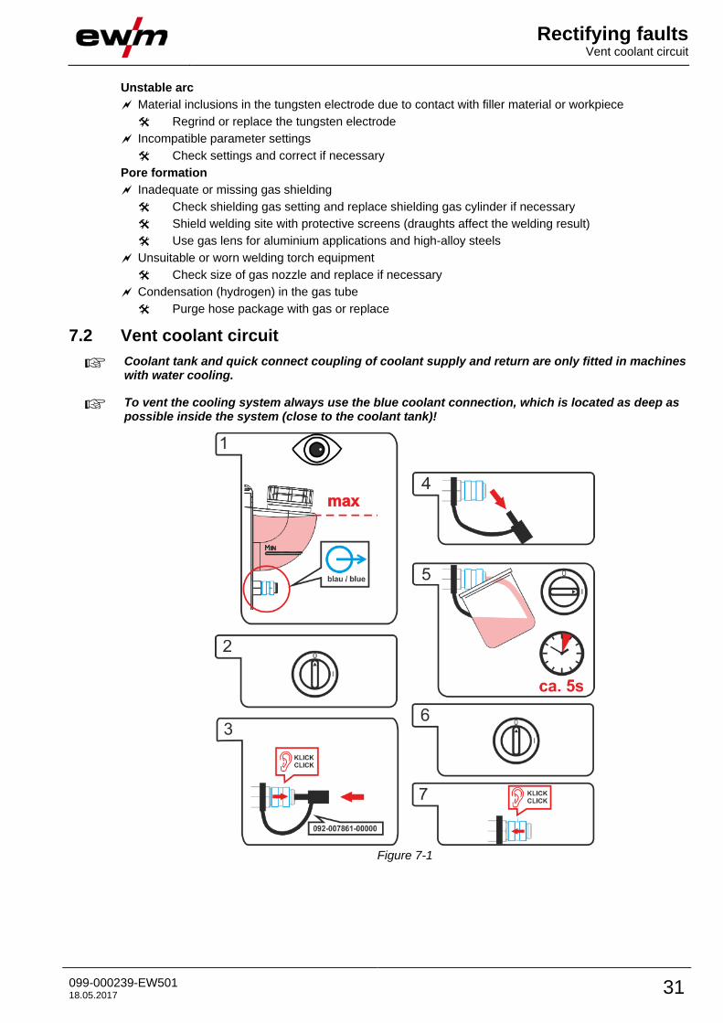
7.2 Vent coolant circuit
Coolant tank and quick connect coupling of coolant supply and return are only fitted in machines with water cooling.
To vent the cooling system always use the blue coolant connection, which is located as deep as possible inside the system (close to the coolant tank)!
Figure 7-1
Technical data Tetrix 230
32 099-000239-EW501 18.05.2017
8 Technical data
Performance specifications and guarantee only in connection with original spare and replacement parts!
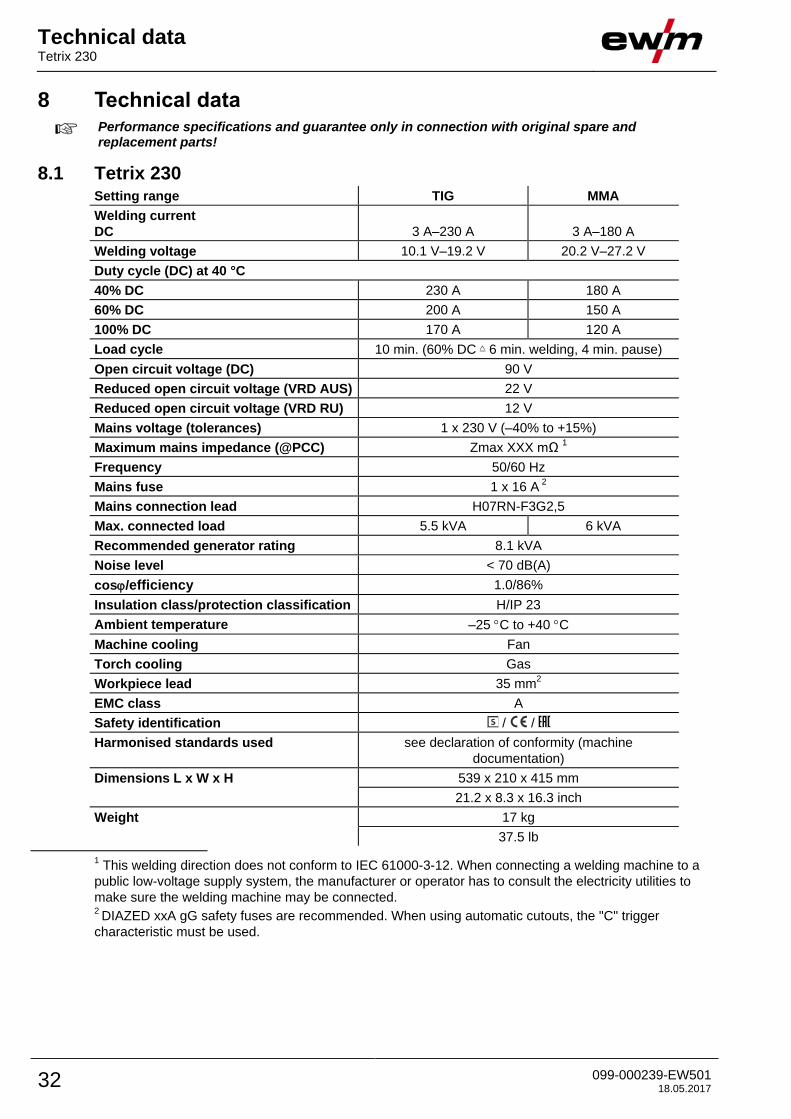
8.1 Tetrix 230 Setting range TIG MMA
Welding current
DC
3 A–230 A
3 A–180 A
Welding voltage 10.1 V–19.2 V 20.2 V–27.2 V
Duty cycle (DC) at 40 °C
40% DC 230 A 180 A
60% DC 200 A 150 A
100% DC 170 A 120 A
Load cycle 10 min. (60% DC 6 min. welding, 4 min. pause)
Open circuit voltage (DC) 90 V
Reduced open circuit voltage (VRD AUS) 22 V
Reduced open circuit voltage (VRD RU) 12 V
Mains voltage (tolerances) 1 x 230 V (–40% to +15%)
Maximum mains impedance (@PCC) Zmax XXX mΩ 1
Frequency 50/60 Hz
Mains fuse 1 x 16 A 2
Mains connection lead H07RN-F3G2,5
Max. connected load 5.5 kVA 6 kVA
Recommended generator rating 8.1 kVA
Noise level < 70 dB(A)
cos/efficiency 1.0/86%
Insulation class/protection classification H/IP 23
Ambient temperature –25 C to +40 C
Machine cooling Fan
Torch cooling Gas
Workpiece lead 35 mm2
EMC class A
Safety identification / /
Harmonised standards used see declaration of conformity (machine
documentation)
Dimensions L x W x H 539 x 210 x 415 mm
21.2 x 8.3 x 16.3 inch
Weight 17 kg
37.5 lb
1 This welding direction does not conform to IEC 61000-3-12. When connecting a welding machine to a
public low-voltage supply system, the manufacturer or operator has to consult the electricity utilities to
make sure the welding machine may be connected. 2 DIAZED xxA gG safety fuses are recommended. When using automatic cutouts, the "C" trigger
characteristic must be used.
Technical data Tetrix 230 AC/DC
099-000239-EW501 18.05.2017 33
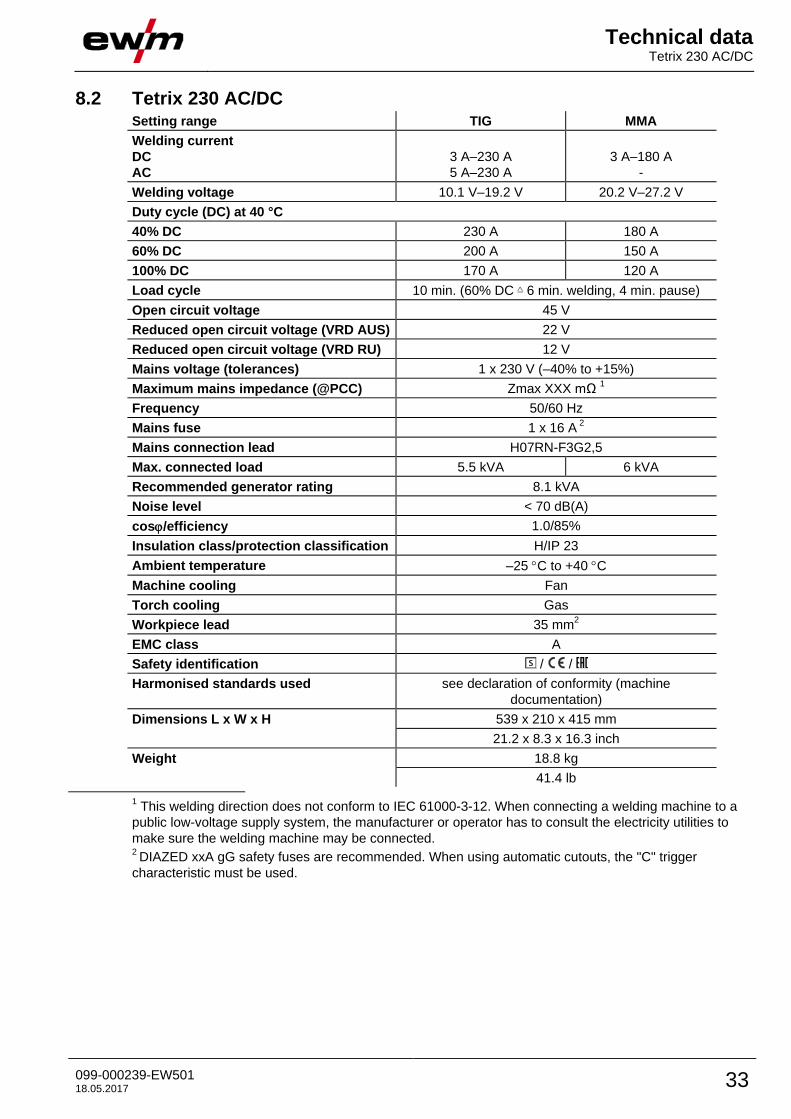
8.2 Tetrix 230 AC/DC Setting range TIG MMA
Welding current
DC
AC
3 A–230 A
5 A–230 A
3 A–180 A
-
Welding voltage 10.1 V–19.2 V 20.2 V–27.2 V
Duty cycle (DC) at 40 °C
40% DC 230 A 180 A
60% DC 200 A 150 A
100% DC 170 A 120 A
Load cycle 10 min. (60% DC 6 min. welding, 4 min. pause)
Open circuit voltage 45 V
Reduced open circuit voltage (VRD AUS) 22 V
Reduced open circuit voltage (VRD RU) 12 V
Mains voltage (tolerances) 1 x 230 V (–40% to +15%)
Maximum mains impedance (@PCC) Zmax XXX mΩ 1
Frequency 50/60 Hz
Mains fuse 1 x 16 A 2
Mains connection lead H07RN-F3G2,5
Max. connected load 5.5 kVA 6 kVA
Recommended generator rating 8.1 kVA
Noise level < 70 dB(A)
cos/efficiency 1.0/85%
Insulation class/protection classification H/IP 23
Ambient temperature –25 C to +40 C
Machine cooling Fan
Torch cooling Gas
Workpiece lead 35 mm2
EMC class A
Safety identification / /
Harmonised standards used see declaration of conformity (machine
documentation)
Dimensions L x W x H 539 x 210 x 415 mm
21.2 x 8.3 x 16.3 inch
Weight 18.8 kg
41.4 lb
1 This welding direction does not conform to IEC 61000-3-12. When connecting a welding machine to a
public low-voltage supply system, the manufacturer or operator has to consult the electricity utilities to
make sure the welding machine may be connected. 2 DIAZED xxA gG safety fuses are recommended. When using automatic cutouts, the "C" trigger
characteristic must be used.

Accessories Remote controls and accessories
34 099-000239-EW501 18.05.2017
9 Accessories
Performance-dependent accessories like torches, workpiece leads, electrode holders or intermediate hose packages are available from your authorised dealer.
9.1 Remote controls and accessories Type Designation Item no.
RTF1 19POL 5 M Foot-operated remote control current with
connection cable
094-006680-00000
RT1 19POL Remote control current 090-008097-00000
RTG1 19POL 5m Remote control, current 090-008106-00000
RTG1 19POL 10m Remote control, current 090-008106-00010
RTP1 19POL Remote control spot welding / pulses 090-008098-00000
RTP2 19POL Remote control spot welding / pulses 090-008099-00000
RTP3 spotArc 19POL spotArc remote control for spot welding / pulses 090-008211-00000
RA5 19POL 5M Remote control e.g. connection cable 092-001470-00005
RA10 19POL 10M Remote control e.g. connection cable 092-001470-00010
RA20 19POL 20M Remote control e.g. connection cable 092-001470-00020
RV5M19 19POLE 5M Extension cable 092-000857-00000
9.2 Welding torch cooling system
Type Designation Item no.
cool40 U31 Cooling module 090-008593-00502
9.3 Transport systems Type Designation Item no.
Trolly 55-5 Transport cart, assembled 090-008632-00000
Trolly 35.2-2 Transport vehicle 090-008296-00000
Trolly 38-2 E Transport vehicle, long wheelbase 090-008270-00000
9.4 General accessories Type Designation Item no.
GH 2X1/4'' 2M Gas hose 094-000010-00001
DM 842 Ar/CO2 230bar 30l D Pressure regulator with manometer 394-002910-00030
5POLE/CEE/16A/M Machine plug 094-000712-00000
9.5 Options Type Designation Item no.
ON 12pol Retox TIG 190/230 Optional retrofit 12-pole connection socket, torch 092-002519-00000
ON TR Trolly 55-5 Cross arm and holder for wire feeder 092-002700-00000
ON Filter TIG 200/300-2 Retrofit option, dirt filter for air inlet 092-002551-00000
ON PC PLUG Protective cap for plug 092-003074-00000

Appendix A Overview of EWM branches
099-000239-EW501 18.05.2017 35
10 Appendix A
10.1 Overview of EWM branches