Embed Size (px)
Citation preview
testo Comfort Software Basic 5
Instruction manual
99 Washington Street Melrose, MA 02176 Phone 781-665-1400Toll Free 1-800-517-8431
Visit us at www.TestEquipmentDepot.com

2

1 Contents
3
1 Contents 1 Contents ................................................................................................... 3
2 About this document ............................................................................... 4
3 Specifications .......................................................................................... 5
3.1. Use .................................................................................................. 5
3.2. System requirements ....................................................................... 5
4 First steps ................................................................................................ 6
4.1. Downloading software ..................................................................... 6
4.2. Installing the software/driver ............................................................ 6
4.3. Starting the software ........................................................................ 8
5 Using the product .................................................................................... 9
5.1. Start page ........................................................................................ 9
5.2. Making settings ................................................................................ 9
5.3. Connect instrument ....................................................................... 10
5.4. Configure instrument ..................................................................... 12
5.5. Import measurement data.............................................................. 15
5.6. Evaluate measurement data .......................................................... 16
6 Tips and assistance ............................................................................... 18
6.1. Questions and answers ................................................................. 18
2 About this document
4
2 About this document
Use
> Please read this documentation through carefully and familiarize yourself with the product before putting it to use. Pay particular attention to the safety instructions and warning advice in order to prevent injuries and damage to the products.
> Keep this document to hand so that you can refer to it when necessary.
> Hand this documentation on to any subsequent users of the product.
Knowledge of Windows® operating systems is required when working with the software.
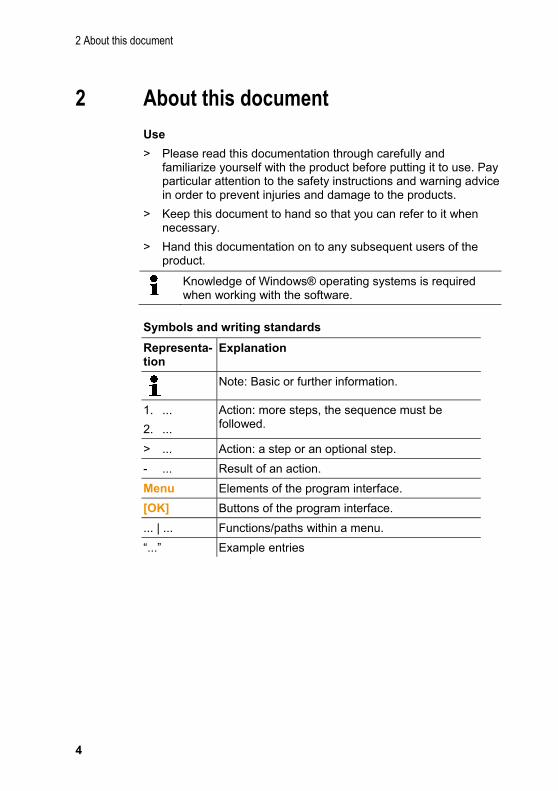
Symbols and writing standards
Representa-tion
Explanation
Note: Basic or further information.
1. ...
2. ...
Action: more steps, the sequence must be followed.
> ... Action: a step or an optional step.
- ... Result of an action.
Menu Elements of the program interface.
[OK] Buttons of the program interface.
... | ... Functions/paths within a menu.
“...” Example entries

3 Specifications
5
3 Specifications
3.1. Use The testo Comfort Software Basic 5 serves the purpose of saving, reading out and analysing individual readings and measurement series. The graphical presentation of readings is the main task of this program.
Readings are measured with Test Data Loggers and transmitted to the PC via an interface.
Reading out data is accomplished with the testo Comfort Software Basic 5, which activates the interfaces and provides all functions.
3.2. System requirements
Operating system
The software will run on the following operating systems:
• Windows® XP ServicePack 3 (SP3)
• Windows Vista
• Windows 7
• Windows 8, Windows 8 Pro, Windows 8 Enterprise
• Others: on request
Computer
The computer must meet the requirements of the corresponding operating system. The following requirements must additionally be fulfilled:
• Interface USB 1.1 or higher
• Internet Explorer 5.0 SP1 or higher
• min. 2 GHz CPU
• min. 1 GB of RAM, but 2 GB of RAM is recommended
Date and time settings will be automatically accepted by the PC. The administrator must make sure that the system time is regularly compared with a reliable time source and adjusted, if necessary, to ensure authenticity of the measurement data.

4 First steps
6
4 First steps
4.1. Downloading software The testo Comfort Software Basic 5 software can be ordered on CD (article no. 0572 0580) if the download from the Internet is not desired.
1. Download testo Comfort Software Basic 5 software in theInternet free of charge at www.testo.com/download-center(registration required).
2. Save Zip file with software.
4.2. Installing the software/driver Administrator rights are required for installation.
If you have already installed Comfort Software version 3.4 or 4.0, please proceed as follows:
1. Update existing software. The updates can be found atwww.testo.com/download-center.
2. Install Comfort Software 5.
3. Delete instrument links from the archive and createthem again via Autodect, see Comfort Software 3.4operating instructions.
1. Select the folder in which the downloaded Zip-file was savedand unpack the Zip-file.
Or
1. Insert the program CD into the CD-ROM drive of the computer.
2. Start the file Setup.exe.
3. Follow the instructions of the installation wizard.
When installing under Vista, please pay attention to the following steps during the installation process:
• The window User account control is opened:
> Click on [Next].
• The window Windows Security is opened:
> Choose Still install this driver software.
4 First steps
7
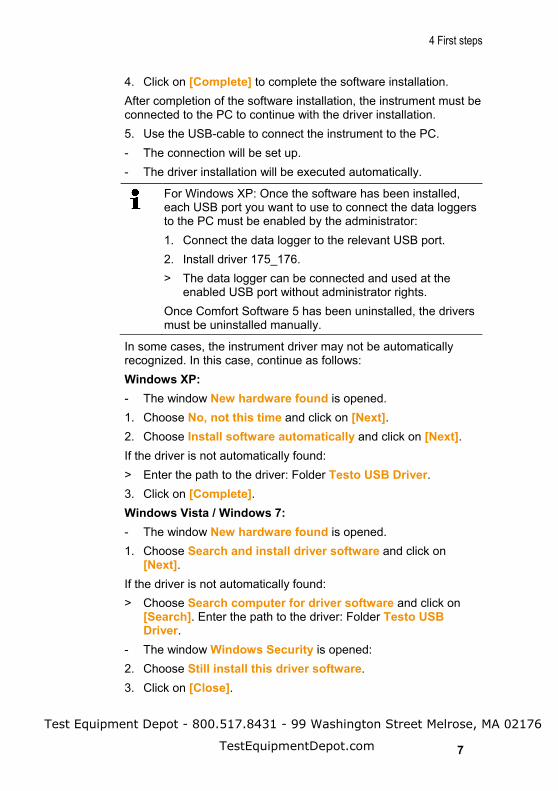
4. Click on [Complete] to complete the software installation.
After completion of the software installation, the instrument must be connected to the PC to continue with the driver installation.
5. Use the USB-cable to connect the instrument to the PC.
- The connection will be set up.
- The driver installation will be executed automatically.
For Windows XP: Once the software has been installed, each USB port you want to use to connect the data loggers to the PC must be enabled by the administrator:
1. Connect the data logger to the relevant USB port.
2. Install driver 175_176.
> The data logger can be connected and used at the enabled USB port without administrator rights.
Once Comfort Software 5 has been uninstalled, the drivers must be uninstalled manually.
In some cases, the instrument driver may not be automatically recognized. In this case, continue as follows:
Windows XP:
- The window New hardware found is opened.
1. Choose No, not this time and click on [Next].
2. Choose Install software automatically and click on [Next].
If the driver is not automatically found:
> Enter the path to the driver: Folder Testo USB Driver.
3. Click on [Complete].
Windows Vista / Windows 7:
- The window New hardware found is opened.
1. Choose Search and install driver software and click on[Next].
If the driver is not automatically found:
> Choose Search computer for driver software and click on [Search]. Enter the path to the driver: Folder Testo USB Driver.
- The window Windows Security is opened:
2. Choose Still install this driver software.
3. Click on [Close].
Test Equipment Depot - 800.517.8431 - 99 Washington Street Melrose, MA 02176
TestEquipmentDepot.com

4 First steps
8
4.3. Starting the software
Starting the Comfort software
The user interface of the software is opened in the language of the operating system, if it is supported. If the language of the operating system is not supported, the user interface is in English.
> Click on [Start] | Programs (Windows XP) or All programs (Windows Vista, Windows 7) | Testo | Comfort Software.
Under Windows Vista the window User account control is opened when the software is started the first time.
> Click on Accept.
5 Using the product
9
5 Using the product
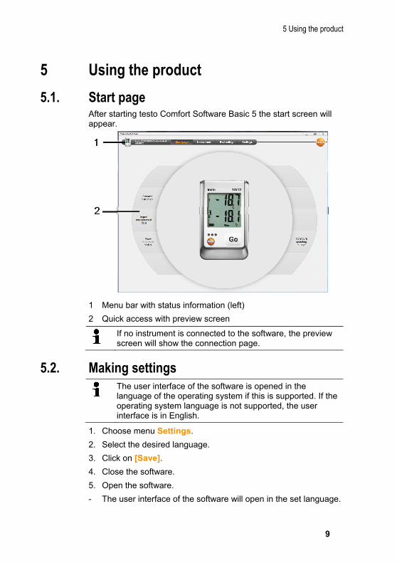
5.1. Start page After starting testo Comfort Software Basic 5 the start screen will appear.
1 Menu bar with status information (left)
2 Quick access with preview screen
If no instrument is connected to the software, the preview screen will show the connection page.
5.2. Making settings The user interface of the software is opened in the language of the operating system if this is supported. If the operating system language is not supported, the user interface is in English.
1. Choose menu Settings.
2. Select the desired language.
3. Click on [Save].
4. Close the software.
5. Open the software.
- The user interface of the software will open in the set language.

5 Using the product
10
5.3. Connect instrument ✓ Instrument connected to PC.
> Choose Connect instrument via start page or menu Instrument | Select instrument.
- Instruments are displayed with picture and type designation.
1 Data loggers (0572 1560, 0572 6560, 0572 1751-1754, 0572 1761-1767) only appear, if they are connected to the PC.
2 Data loggers (0563 1741, 0563 1754-1761, 0563 1771-1775, 0554 1778) appear by default each time the software is started.
3 Selection field for all data loggers (2), to choose the associated COM-Port.
5 Using the product
11
For data loggers (0572 1560, 0572 6560, 0572 1751-1754, 0572 1761-1767)
1. Choose the instrument and click on [Connect].
Only one instrument can be connected at a time.
- The instrument appears in the status display to the left of the menu bar.
- The button [Connect] changes to [Disconnect].
- The Instrument | Status is displayed.
The status display only serves the purpose of information. The values cannot be edited.
For data loggers (0563 1741, 0563 1754-1761, 0563 1771-1775, 0554 1778)
1. Choose the COM-Port (usually the COM-Port with the highestnumber, otherwise see section under "If not possible to connect").
2. Choose the desired instrument and click on [Connect].
Only one instrument can be connected at a time.
- The instrument appears in the status display to the left of the menu bar.
- The button [Connect] changes to [Disconnect].
- The Instrument | Show instrument status is displayed.
The status display only serves the purpose of information. The values cannot be edited.
If not possible to connect:
Under Windows XP:
1. Choose Start | Settings | System control | System |Hardware | Device manager.
Under Windows Vista:
1. Choose Start | System control | System and maintenance |Device manager.

5 Using the product
12
Under Windows 7:
1. Choose Start | System control | System and security |System | Device manager.
2. Click on Connections (COM and LPT).
- The entries of these categories are displayed.
3. Search for entries "Testo ...", followed by a COM interfacenumber.
4. Select this individual COM interface number in the selectionfield (3).
5. Click on [Connect].
The COM interface number will only remain equal if you connect the USB interface always to the same USB-port or leave it plugged in.
5.4. Configure instrument
✓ The instrument is connected with testo Comfort Software Basic 5 and is displayed in the status bar, see Connect instrument page 10.
✓ Instrument is not in Rec-mode. If necessary click on [Stop measurement].
5 Using the product
13
1. Choose Configure operation settings via the start page or themenu Instrument | Configure instrument | Operationsettings.
2. Make the desired settings (instrument specific) for
• Start criteria
◦ Start time: The instrument starts at the pre-set time.
◦ Start button on instrument: Hold [Go] depressed for longerthan 3 seconds.
◦ Software start: Click on [Start measurement].
◦ Formula: With formula start, explicit process events maybecome the start point of the measurement. For eachmeasuring channel, a formula can be assigned, which canthen additionally be linked by operators. The instrument willonly start measuring after the limiting value of the enteredformula is exceeded. The measurement will therefore onlystop when the software is terminated: Click on [Stopmeasurement].
• Stop criteria
◦ Memory full: The instrument stops the measurement assoon as the memory is full.
◦ Circular buffer memory: If the memory is full, the instrumentwill first overwrite the "oldest" readings. The measurementwill therefore only stop when the software is terminated:Click on [Stop measurement].
◦ Number of readings: The instrument stops the measurementas soon as the defined number of readings has beenobtained.
• Storage cycle determines the frequency with which the readingsare saved. The storage cycle must be a multiple of themeasuring interval.
• Measuring interval determines the frequency with which thereadings can be recorded and displayed (e.g. via the display).
• Unit determines the unit used to record and display the readingsin the display.
5 Using the product
14
• Channel settings: Enter channel designation and limiting values.
With sensors connected: Select the sensor type.
With connections closed with blanking plugs: Choose switchedoff.
With sensors connected the channel number refers to the port number printed on the instrument housing.
Without assignment of the sensor type to the correct instrument port the instrument will not record any sensor readings.
3. Change to the tab Instrument configuration.
4. Enter instrument name (max. 15 characters) and description(max. 70 or 265 characters depending on the instrument), andcarry out display settings.
5. Click on [Transfer to instrument].
- Configuration is completed.
> If Software start has been selected as a start criterion: [Start measurement].
Template
By using templates one can save the configuration settings for later instrument configurations.
1. Enter text under Choose template.
2. Click on [Save as template].
To call up a saved configuration:
1. Enter the name of the desired template into the selection field.
- The saved settings are displayed.
2. Click on [Transfer to instrument].
- The settings are transferred to the data logger.

5 Using the product
15
5.5. Import measurement data
From the instrument
✓ The instrument is connected to the PC and has recorded
measurement data. 1. Choose Import of measurement data from the start page or
via menu Evaluating | Import measurement data | Import measurement data.
- Details concerning measurement data like instrument name, serial number and location are displayed.
2. Click on the folder icon to select the path under which themeasurement data are to be saved.
3. Click on [Import].
- The screen changes to the tab Import history.
- The status bar of the current import and previously performed import processes are displayed.
- Once the import of measurement data has been completed the display will change to the Evaluation section.
From SD-card
✓ Measurement data were copied to the SD-card, see operating
instructions of the instrument.
✓ SD-card connected to PC.
1. Select menu Evaluating | Evaluate measurement data.
2. Click on [Open file].
5 Using the product
16
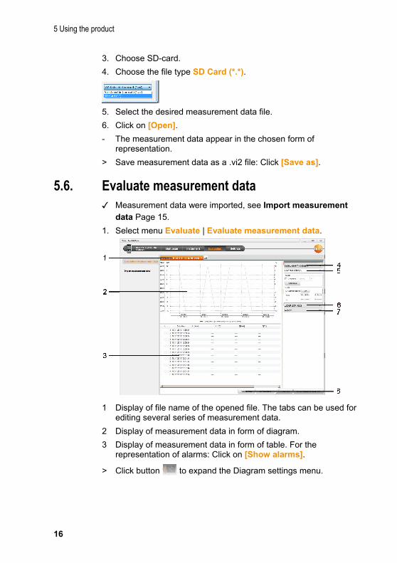
3. Choose SD-card.
4. Choose the file type SD Card (*.*).
5. Select the desired measurement data file.
6. Click on [Open].
- The measurement data appear in the chosen form of representation.
> Save measurement data as a .vi2 file: Click [Save as].
5.6. Evaluate measurement data ✓ Measurement data were imported, see Import measurement
data Page 15.
1. Select menu Evaluate | Evaluate measurement data.
1 Display of file name of the opened file. The tabs can be used for editing several series of measurement data.
2 Display of measurement data in form of diagram.
3 Display of measurement data in form of table. For the representation of alarms: Click on [Show alarms].
> Click button to expand the Diagram settings menu.

5 Using the product
17
4 Make settings for the measuring channels.
5 Make settings for the diagram. Zoom inside diagram with the mouse wheel.
6 Export selected measurement data into new report or to clipboard.
7 Print or export report.
With [Print report] one can make settings to the report form, via [Start export] you use a standard report form and the file is directly saved.
For the html export format, 50,000 measured values can be exported per file. For the xls export format, 65,000 measured values can be exported per worksheet and 650,000 per Excel file. If the number of measured values is above the maximum possible value per file, additional files are generated.
8 Send measurement data by e-mail: Click on [send e-mail].
The PC must have an e-mail program installed.
6 Tips and assistance
18
6 Tips and assistance
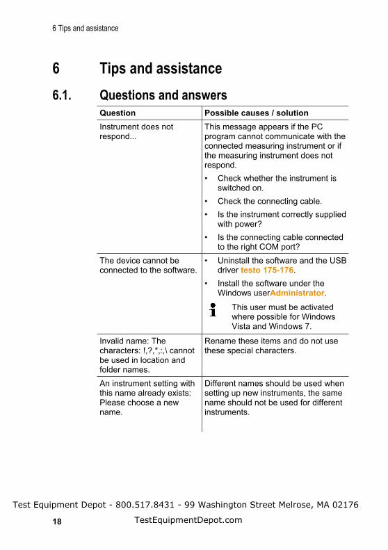
6.1. Questions and answers Question Possible causes / solution
Instrument does not respond...
This message appears if the PC program cannot communicate with the connected measuring instrument or if the measuring instrument does not respond.
• Check whether the instrument isswitched on.
• Check the connecting cable.
• Is the instrument correctly suppliedwith power?
• Is the connecting cable connectedto the right COM port?
The device cannot be connected to the software.
• Uninstall the software and the USBdriver testo 175-176.
• Install the software under theWindows userAdministrator.
This user must be activated where possible for Windows Vista and Windows 7.
Invalid name: The characters: !,?,*,:,\ cannot be used in location and folder names.
Rename these items and do not use these special characters.
An instrument setting with this name already exists: Please choose a new name.
Different names should be used when setting up new instruments, the same name should not be used for different instruments.
Test Equipment Depot - 800.517.8431 - 99 Washington Street Melrose, MA 02176
TestEquipmentDepot.com