Embed Size (px)
Citation preview

EN
W415-1087 / A / 06.06.13
FRPG41
INSTALLER: LEAVE THIS MANUAL WITH THE APPLIANCE.CONSUMER: RETAIN THIS MANUAL FOR FUTURE REFERENCE.
NEVER LEAVE CHILDREN OR OTHER AT RISK INDIVIDUALS ALONE WITH THE APPLIANCE.
INSTALLATION AND OPERATING INSTRUCTIONS
1.10C
Wolf Steel Ltd., 24 Napoleon Rd., Barrie, ON, L4M 0G8 Canada / 103 Miller Drive, Crittenden, Kentucky, USA, 41030
Phone (705)721-1212 • Fax (705)722-6031 • www.napoleonfi replaces.com • [email protected]
SAFETY INFORMATION
! WARNINGIf the information in these instructions is not followed
exactly, a fi re or explosion may result causing property damage, personal injury or death. Improper installation, adjustment, alteration, service or maintenance can cause injury or property damage, bodily injury or even death.
Please read entire manual before you install and use your appliance.
- This appliance can be very hot when burning. - Combustible materials such as fi rewood, wet clothing, etc. placed
too close can catch fi re. - Children and pets must be kept from touching the appliance when it
is hot. - The chimney must be sound and free of cracks. Before installing
this unit, contact the local building or fi re authority and follow their guidelines.
- Operate only with the door tightly closed. - Burn wood behind the log retainer directly on the fi rebricks. - Do not use an elevated grate or otherwise raise the fi re. - At least 14 square inches (90.3 square centimeters) of outside air
must be admitted to the room or directly to the unit through a 4” (101.6mm) diameter pipe.
- This appliance is designed to burn natural wood only. Higher effi ciencies and lower emissions generally result when burning air dried seasoned hardwoods, as compared to softwoods or to green or freshly cut hardwoods.
- Do not start a fi re with chemicals or fl uids such as gasoline, engine oil, etc.
- Do not burn treated wood, coal, charcoal, coloured paper, cardboard, solvents or garbage.
- Do not let the appliance become hot enough for any part to glow red.- KEEP THE STOVE TOP TEMPERATURE BELOW 700°F (371°C).
Attempts to achieve heat output rates that exceed design specifi cations can result in steel distortion and damage.
$10.00
HOT GLASS WILL CAUSE BURNS.
DO NOT TOUCH GLASS UNTIL COOLED.
NEVER ALLOW CHILDREN TO TOUCH GLASS.
! WARNING
CERTIFIED UNDER U.S. ENVIRONMENTAL PROTECTION AGENCY (E.P.A.) JULY 1990 40 C.F. R. PART 60 AND THE OREGON DEPARTMENT OF ENVIRONMENTAL QUALITY (D.E.Q.) PARTICULATE EMISSION STANDARDS BY E.E.M.C THESE APPLIANCES HAVE BEEN TESTED AND LISTED BY OMNI
TESTING SERVICES TO STANDARDS: ULC-S628, UL1482.
EPI3WOOD INSERT
Report #415-S-11-2

W415-1087 / A / 06.06.13
2
EN
NOTE: Changes, other than editorial, are denoted by a vertical line in the margin.
TABLE OF CONTENTS1.0 INSTALLATION OVERVIEW 32.0 INTRODUCTION 4
2.1 DIMENSIONS (COMPLETE WITH CAST SURROUND) 52.2 SPECIFICATIONS 52.3 GENERAL INSTRUCTIONS 62.4 GENERAL INFORMATION 72.5 E.P.A. COMPLIANCE 72.6 RATING PLATE INFORMATION 8
3.0 PRE-INSTALLATION PREPARATION 93.1 MINIMUM CLEARANCE TO COMBUSTIBLES 93.2 HEARTH EXTENSION/FLOOR PROTECTION 10
4.0 INSTALLATION 114.1 TYPICAL EXISTING MASONRY 124.2 INSTALLING THE EPI3 134.3 FACTORY BUILT FIREPLACE 14
5.0 FINISHING 145.1 SECONDARY AIR TUBES 145.2 BRICKS AND BAFFLE INSTALLATION 155.3 SURROUND INSTALLATION, TRADITIONAL CAST 165.4 SURROUND INSTALLATION, CONTEMPORARY CAST 17
6.0 OPERATION 186.1 AIR CONTROL 196.2 FIRE EXTINGUISHERS / SMOKE DETECTORS 196.3 FUEL 196.4 LIGHTING A FIRE 20
6.4.1 FLASH FIRE 206.4.2 EXTENDED FIRE 20
6.5 SMOKING 206.6 BLOWER OPERATION 21
7.0 MAINTENANCE 227.1 ASH REMOVAL PROCEDURES 227.2 CREOSOTE FORMATION AND REMOVAL 227.3 RUNAWAY OR CHIMNEY FIRE 237.4 CHIMNEY CLEANING 247.5 DOOR REMOVAL 247.6 LATCH BLOCK MECHANISM REPLACEMENT 257.7 GLASS / GASKET REPLACEMENT 267.8 CARE OF GLASS 277.9 CARE OF PLATED PARTS 277.10 BLOWER SERVICE OR REPLACEMENT 287.11 WOOD 29
8.0 REPLACEMENTS 309.0 TROUBLESHOOTING 3510.0 WARRANTY 3611.0 SERVICE HISTORY 3712.0 NOTES 38

W415-1087 / A / 06.06.13
3
EN
1.0 INSTALLATION OVERVIEW
Rating plate, see “RATING PLATE INFORMATION” section. Blower, see “BLOWER
OPERATION” section.
Door, see “DOOR REMOVAL AND HANDLE REPLACEMENT” section.
Flashing, see “SURROUND INSTALLATION” section.
Draft, see “AIR CONTROL” section.

W415-1087 / A / 06.06.13
4
EN
2.0 INTRODUCTION
3.17D
! WARNING• THIS APPLIANCE IS HOT WHEN OPERATED AND CAN CAUSE SEVERE BURNS IF CONTACTED.• ANY CHANGES OR ALTERATIONS TO THIS APPLIANCE OR ITS CONTROLS CAN BE DANGEROUS AND
IS PROHIBITED.• Do not operate appliance before reading and understanding operating instructions. Failure to operate appliance
according to operating instructions could cause fi re or injury.• Before installing this appliance, contact the local building or fi re authority and follow their guidelines.• This appliance must be installed by a qualifi ed installer. • Risk of burns. The appliance should be turned off and cooled before servicing.• Do not operate without fully assembling all components.• Do not let the appliance become hot enough for any part to glow red.• Do not install damaged, incomplete or substitute components.• Risk of cuts and abrasions. Wear protective gloves and safety glasses during installation. Sheet metal edges
may be sharp.• Children and adults should be alerted to the hazards of high surface temperature and should stay away to avoid
burns or clothing ignition. • Young children should be carefully supervised when they are in the same room as the appliance. Toddlers,
young children and others may be susceptible to accidental contact burns. A physical barrier is recommended if there are at risk individuals in the house. To restrict access to an appliance or stove, install an adjustable safety gate to keep toddlers, young children and other at risk individuals out of the room and away from hot surfaces.
• Clothing or other fl ammable material should not be placed on or near the appliance. Objects placed in front of the appliance must be kept a minimum of 48” (1219.2mm) away from the front face of the appliance.
• Due to high temperatures, the appliance should be located out of traffi c and away from furniture and draperies.• Ensure you have incorporated adequate safety measure to protect infants/toddlers from touching hot surfaces.• Even after the appliance is out, the glass and/or screen will remain hot for an extended period of time.• Check with your local hearth specialty dealer for safety screens and hearth guards to protect children from hot
surfaces. These screens and guards must be fastened to the fl oor.• Any safety screen or guard removed for servicing must be replaced prior to operating the appliance.• Under no circumstances should this appliance be modifi ed.• This appliance must not be connected to a chimney fl ue pipe servicing a separate solid fuel burning appliance.• Do not operate the appliance with the glass door removed, cracked or broken. Replacement of the glass should
be done by a licensed or qualifi ed service person.• Do not strike or slam shut the appliance glass door.• Operate only with the doors tightly closed.• Only doors / optional fronts certifi ed with the unit are to be installed on the appliance.• Keep the packaging material out of reach of children and dispose of the material in a safe manner. As with all
plastic bags, these are not toys and should be kept away from children and infants.• If the appliance is not properly installed, a house fi re may result. Do not expose the appliance to the elements
(ex. rain, etc.) and keep the appliance dry at all times. Wet insulation will produce an odour when the appliance is used.
• The chimney must be sound and free of cracks. Clean your chimney a minimum of twice a year and as required.• Do not start a fi re with chemicals or fl uids such as gasoline, engine oil, etc.• Your appliance requires periodic maintenance and cleaning. Failure to maintain your appliance may lead to
smoke spillage in your home.• Higher effi ciencies and lower emissions generally result when burning air dried seasoned hardwoods, as
compared to softwoods or too green or freshly cut hardwoods. Burning wet unseasoned wood can cause excessive creosote accumulation. When this is ignited it can cause a chimney fi re that may result in a serious house fi re.
• This appliance is designed to burn natural wood only. Do not burn treated wood, coal, charcoal, coloured paper, cardboard, solvents or garbage.
• Burn wood directly on the fi rebricks. Do not elevate grate or otherwise raise the fi re.• Do not store wood within appliance installation clearances or within the space required for re-fueling and ash
removal.• Ashes must be disposed in a metal container with a tight lid and placed on a non-combustible surface well away
from the home or structure until completely cool.• Ensure clearances to combustibles are maintained when building a mantel or shelves above the appliance.
Elevated temperatures on the wall or in the air above the appliance can cause melting, discolouration or damage to decorations, a T.V. or other electronic components.

W415-1087 / A / 06.06.13
5
EN
2.1 DIMENSIONS (COMPLETE WITH CAST SURROUND)
EPI3T TRADITIONAL MODEL
EPI3C CONTEMPORARY MODEL
29 1/2"749mm
21 5/16"541mm18"
457mm
17 5/16"440mm
5 1/8"130mm
42 1/2"1080mm
26 1/2"673mm
21 1/2"546mm
6"152mm
28 1/2"724mm
21 5/16"541mm18"
457mm
17 5/16"440mm
5 1/8"130mm
42 1/2"1080mm
26 1/2"673mm
21 1/2"546mm
6"152mm
** Figures will vary considerably with individual conditions.*** Wolf Steel Ltd. estimated realistic BTU/hr with cordwood logs and regular refueling.
Specifi cations EPI3CHAMBER (D.W.H) 13 3/4” x 20 7/8” x 11 1/2”
(349.3mm) x (530.3mm) x (292.1mm)CAPACITY 1.8 ft3 (0.05 m3)APPROX. AREA HEATED** 1500 ft2 (139.4 m2)HEAT OUTPUT (HIGH BURN) *** 55,000 BTUDURATION LOW FIRE** 8 HoursWEIGHT COMPLETE 400 lbs (181.4 kg)WEIGHT OF BRICKS 80 lbs (36.3 kg)WEIGHT WITHOUT CAST SURROUND (COMPLETE WITH DOOR) AND BRICKS
250 lbs(113.4 kg)
2.2 SPECIFICATIONS

W415-1087 / A / 06.06.13
6
EN
• Before beginning your installation, consult with your local building code agency or fi re offi cials and insurance representative to ensure compliance.
• Non-toxic smoke will be emitted during the paint curing process, to help dissipate the smoke open a window near the appliance.
• Remove any dust or debris off the top of the appliance before fi ring the appliance as the paint will become soft as the appliance heats up and will harden as the appliance cures. To cure the paint on your appliance burn your appliance moderately hot during the fi rst few fi res.
• To keep the gasket from sticking to the appliance as the paint is curing, periodically open the door every 5-10 minutes.
• For the fi rst two weeks use generous amounts of fuel and burn the appliance with the damper wide open for an hour as the appliance goes through a process of eliminating moisture in the steel and fi rebricks. The initial heat output will be reduced while the moisture is bring drawn from the appliance and it will be necessary to build several hot fi res to remove this moisture. DURING THIS PROCESS DO NOT OVER FIRE THE APPLIANCE. REDUCE THE AMOUNT OF AIR COMING INTO THE APPLIANCE IF THE APPLIANCE OR CHIMNEY BECOMES RED.
2.3 GENERAL INSTRUCTIONS
4.7
ALL WIRING SHOULD BE DONE BY A QUALIFIED ELECTRICIAN AND SHALL BE IN COMPLIANCE WITH LOCAL CODES. IN THE ABSENCE OF LOCAL CODES, USE THE CURRENT CSA22.1 CANADIAN
ELECTRIC CODE IN CANADA OR THE CURRENT NATIONAL ELECTRIC CODE ANSI/NFPA NO. 70 IN THE UNITED STATES.
THIS APPLIANCE HAS NOT BEEN TESTED WITH ANY VENTED OR UNVENTED GAS LOG SET. TO REDUCE RISK OF FIRE OR PREVENT INJURY, DO NOT INSTALL A VENTED OR UNVENTED GAS LOG
SET INTO THE APPLIANCE.
BURNING YOUR UNIT WITH THE ASH DUMP DOOR OPEN OR AJAR CREATES A FIRE HAZARD THAT MAY RESULT IN DISCOLOURATION TO THE GOLD PLATED DOOR, INTERNAL DAMAGE TO THE
APPLIANCE OR A HOUSE CHIMNEY FIRE.
DO NOT CONNECT THIS APPLIANCE TO A CHIMNEY FLUE SERVING ANOTHER APPLIANCE.
THIS APPLIANCE AND IT’S COMPONENTS ARE DESIGNED TO BE INSTALLED AND OPERATED AS A SYSTEM. ANY ALTERATION TO OR SUBSTITUTION FOR ITEMS IN THIS SYSTEM, UNLESS ALLOWED BY THESE INSTALLATION INSTRUCTIONS, WILL VOID THE LISTING AND MAY VOID THE PRODUCT
WARRANTY. IT MAY ALSO CREATE A HAZARDOUS INSTALLATION. READ THROUGH THESE INSTRUCTIONS THOROUGHLY BEFORE STARTING YOUR INSTALLATION AND FOLLOW THEM
CAREFULLY THROUGHOUT YOUR PROJECT.
! WARNING

W415-1087 / A / 06.06.13
7
EN
2.4 GENERAL INFORMATIONYour appliance was specifi cally designed to meet the July 1990 particulate emission standards and has been extensively tested in Canadian and US laboratories. This system is the most effi cient, simple and trouble free we know; it works as follows:
Your appliance uses clean-burning technology found in all Napoleon EPA certifi ed stoves equipped with an heat circulating blower . External modifi cations have been made to allow its installation as a “functional insert” with a heat circulating blower system and a means of enclosing the solid fuel burning fi replace cavity for greater heating effi ciency.
Your appliance must be installed only into a solid fuel burning fi replace that is at least 18” (457.2mm) deep, 27” (685.8mm) wide and 22” (558.8mm)high with an approved lined chimney at least 15 feet high (4.6m) and a hearth of 18” (457.2mm) for Canada and 16” (406.4mm) for USA. This minimum recess can only be achieved if the opening height is suffi cient enough to allow the connector to fi t under the noncombustible facing. The appliance and chimney must be constructed in accordance with all national and local building code standards.
The chimney vent system used on your wood burning appliance should be designed with the least amount of restriction possible to enable the exhaust products to easily fl ow through it. Chimney vent systems that are too short or too long can also have an adverse affect on the fl ow of exhaust through it. The wood burning appliance and chimney vent system also require a suffi cient supply of combustion air not only to support the combustion in the combustion chamber but to replace the exhaust leaving it so it can fl ow freely up through the vent system and out into the atmosphere. It is the correct balance of combustion air and the chimney vent system that will ensure the appliance provides you with its optimum performance.
Secondary air from the side intake openings travels up to the secondary air housing to the manifold located across the top and fl ows out laterally to oxidize the gases below the smoke exit.
The combustion chamber is lined with high temperature refractory fi rebricks on the sides, back and bottom with a fi bre baffl e on top to maintain a high temperature in the combustion chamber so that gases mixing with the preheated air from the secondary air manifold tubes are easily ignited and burned.
Be sure to provide suffi cient combustion air. There are many other appliances in your home competing for air such as: a kitchen range hood, forced air heating devices or a bathroom exhaust fan.
Expansion / contraction noises during heating up and cooling down cycles are normal and to be expected.
After extended periods of non-operation such as following a vacation or a warm weather season, the appliance may emit a slight odour for a few hours. This is caused by dust particles on the fi rebox burning off. Open a window to suffi ciently ventilate the room.
2.5 E.P.A. COMPLIANCECALIFORNIA PROP 65 WARNING:Use of this product may produce smoke which contains chemicals known to the State of California to cause cancer, birth defects, or other reproductive harm.
If you experience smoking problems, you may need to open a door, a window or otherwise provide some method of supplying combustion air to the appliance.
We suggest that our woodburning hearth products be installed and serviced by professionals who are certified in the U.S. by the National Fireplace Institue® (NFI) as NFI Woodburning Specialists or who are certified in Canada by Wood Energy Technical Training (WETT).
AIR INLET PATH
EXHAUST PATH

W415-1087 / A / 06.06.13
8
EN
2.6 RATING PLATE INFORMATION
For rating plate location, see “INSTALLATION OVERVIEW” section.
This illustration is for reference only. Refer to the rating plate on the appliance for accurate information. For French rating plate remove the plate, fl ip over and reattach.
NOTE: The rating plate must remain with the appliance at all times. It must not be removed.
EPI3 , LISTED SOLID FUEL BURNING FIREPLACE INSERT. TESTED TO ULC S628-93 / UL 1482-2011CHIMNEY CONNECTOR: 6” (152mm) DO NOT CONNECT THIS UNIT TO A CHIMNEY FLUE SERVING ANOTHER APPLIANCE.FUEL: FOR USE WITH SOLID WOOD FUEL ONLY. DO NOT USE GRATE OR ELEVATE FIRE - BUILD WOOD FIRE DIRECTLY ON HEARTH.
WARNING: RISK OF SMOKE SPILLAGE. OPERATE ONLY WITH DOOR FULLY CLOSED. REPLACE GLASS ONLY WITH THE CERAMIC GLASS. DO NOT OVERFIRE. IF HEATER OR CHIMNEY CONNECTORS GLOW, YOU ARE OVERFIRING. INSPECT AND CLEAN CHIMNEY FREQUENTLY. UNDER CERTAIN CONDITIONS OF USE, CREOSOTE BUILD UP MAY OCCUR RAPIDLY.BLOWER KIT: 115V, 60HZ, 1.5AMP. ROUTE CORD AWAY FROM UNIT.DANGER: RISK OF ELECTRICAL SHOCK. DISCONNECT POWER BEFORE SERVICING UNIT.
INSTALL AND USE ONLY IN ACCORDANCE WITH THE MANUFACTURER’S INSTALLATION AND OPERATION INSTRUCTIONS. INSTALL AND USE ONLY IN MASONRY FIREPLACE OR FACTORY BUILT FIREPLACE. CONTACT LOCAL BUILDING OR FIRE OFFICIALS ABOUT RESTRICTIONS AND INSTALLATION INSPECTION IN YOUR AREA.HEARTH EXTENSION/FLOOR PROTECTION:MUST BE NON COMBUSTABLE AND HAVE A MINIMUM THICKNESS OF 0.5” WITH A THERMAL CONDUCTIVITY FACTOR (K) 0.84 AND RESISTANCE VALUE (R) 0.59.CAUTION:
HOT WHILE IN OPERATION. DO NOT TOUCH. KEEP CHILDREN AND CLOTHING AND FURNITURE AWAY. CONTACT MAY CAUSE SKIN BURNS.
MINIMUM CLEARANCE TO COMBUSTIBLE MATERIALS (MEASURED FROM INSERT BODY)
A ADJACENT SIDEWALL A) 12”/305mm B MANTEL B) 16”/406mmC TOP FACING C) 16”/406mmD SIDE FACING D) 6”/152mm
EPI3DATE CODE
W385-0678
Pour le français, l'étiquette arrière.INSTALL ONLY ON A NON-COMBUSTIBLE HEARTH RAISED (F) 1.5 IN / 38MM ABOVE AN ADJACENT COMBUSTIBLE FLOOR. COMBUSTIBLE FLOOR MUST BE PROTECTED BY NON-COMBUSTIBLE MATERIAL EXTENDING (E) 16 in / 450MM (US), 18 IN / 456MM (CAN) TO FRONT AND (G) 8 IN / 205 MM TO SIDES FROM FUEL DOOR. FOR ADDITIONAL MANTEL INFORMATION SEE OWNER’S INSTRUCTION MANUAL
NAC GUANGZHOU P.R.C.NO.69 HEFENG ROAD, GUANGZHOU,CHINA
24 NAPOLEON ROAD, BARRIE, ON, L4M 0G8 CANADA
WOLF STEEL LTD.
U.S. Environmental Protection Agency Certified to comply with July 1990, particulate emissions standards: /40 CFR Part 60, Subpart AAA
NAC214 BAYVIEW DRIVE, BARRIE, ON L4N 4Y8 CANADA
103 MILLER DRIVECRITTENDEN, KY 41030-7560
WOLF STEEL USA
415-S-11-2
A
C
D
B
EPI3, FOYER ENCASTRÉ À COMBUSTIBLE SOLIDE HOMOLOGUÉ. TESTÉ SELON LES NORMES ULC S628-93 / UL 1482-2011
AVERTISSEMENT : RISQUE D’ÉCHAPPEMENT DE FUMÉE. TENIR LA PORTE FERMÉE LORSQUE LE POÊLE FONCTIONNE. EMPLACEZ LA VITRE PAR UNE VITRE EN CÉRAMIQUE SEULEMENT. NE SURCHAUFFEZ PAS L’APPAREIL. SI L’APPAREIL OU LES RACCORDS ROUGEOIENT, L’APPAREIL SURCHAUFEE. INSPECTEZ ET NETTOYEZ LA CHEMINÉE FRÉQUEMMENT. DANS CERTAINES CONDITIONS, DES DÉPÔTS DE CRÉOSOTE PEUVENT SE FORMER RAPIDEMENT.
INSTALLER ET UTILISER SELONS LES INSTRUCTIONS DU FABRICANT. INSTALLER ET UTILISER DANS UN FOYER DE MACONNERIE OU PRÉFABRIQUÉ. APPELER VOTRE INSPECTEUR DE BÂTIMENT OU LE DÉPARTMENT D’INCENDIE LOCAL POUR LES CODES LOCAUX ET POUR INSPECTÉE VOTRE INSTALLATION ET FOYER.
ATTENTION :QUAND L’APPAREIL FONCTIONNE, LA SURFACE DEVIENT CHAUDE. NE PAS TOUCHER. TENIR LES ENFANTS, LES VÊTEMENTS ET LES MEUBLES À L’ÉCAR. LE CONTACT PEUT CAUSER DES BRÛLURES À LA PEAU. W385-0679
INSTALLER SUR UN ÂTRE DE MATÉRIAUX INCOMBUSTIBLE SURÉ-LEVÉ (F) 1,5 POUCES / 38MM DESSUS DU PLANCHER COMBUSTIBLE ADJACENT. LE PLANCHER COMBUSTIBLE DOIT ÊTRE PROTÉGÉ PAR LE MATERIAUX INCOMBUSTIBLE QUI ÉTENDRE. (E) 16 IN / 405MM (ETATS-UNIS) 18 IN / 457MM (CAN) EN AVANT ET (G) 8IN / 205MM LES CÔTÉ DE LA PORTE. POUR DE PLUS AMPLES RENSEIGNEMENTS SUR LE MANTEAU, CONSULTEZ LE MANUEL D’INSTRUCTIONS.
U.S. Environmental Protection Agency Certifié conforme à la norme d’ émanation de particles de juillet 199040 CFR Part 60, Subpart AAA
B DÉGAGEMENTS AUX MATÉRIAUX COMBUSTIBLES: (À PARTIR DE L’APPAREIL)
A CÔTÉ A) 12”/305mm B DESSUS B) 16”/406mmC TABLETTE C) 16”/406mmD MUR LATÉRAL D) 6”/152mm
For English see Reverse
Pour la date et le numéro de série, voir le revers.
415-S-11-2
SOUFFLERIE: 115V, 60HZ, 1.5AMP. TENEZ LE CORDON ÉLECTRIQUE LOIN DE L’APPAREIL.DANGER: RISQUE DE SECOUSSE ÉLECTRIQUE. DÉBRANCHEZ AVANT DE PROCÉDER À L’ENTRETIEN.RACCORD DE CHEMINÉE : 6” (152mm) NE PAS RACCORDER À LA CHEMINÉE D’UN AUTRE APPAREIL.COMBUSTIBLE : POUR USAGE AVEC LE BOIS SOLIDE SEULEMENT. N’UTILISEZ PAS DE CHENET OU NE SURÉLEVEZ PAS LE BOIS - PRÉPAREZ LE FEU DIRECTEMENT SUR L’ÂTRE.
BASE DE PROTECTION/ PROTECTION DE PLANCHER: DOIT ÊTRE INCOMBUSTIBLE ET AVOIR UNE ÉPAISSEUR MINIMALE DE 0,5” AVEC UN COEFFICIENT DE CONDUCTIVITÉ THERMIQUE (K) DE 0,84 ET UN COEFFICIENT DE RÉSISTANCE THERMIQUE (R) DE 0.59.
A
C
DSAMPLEMPLEMPLEUL 1482-2011
ACCORDANS INSTALLATION
NS. INSTALL REPLACE OR
T FIREPLACE. CONTACT DING OR FIRE OFFICIALS ABOUT
TIONS ANDON IN YOUR
RTH EXTENSION/FLOOR PROTECTIO
PLMUST BE NON COMBUSTABLE AND HAVEMINIMUM THICKNESS OF 0.5” WITH A THECONDUCTIVITY FACTOR (K) 0.84 AND RESISTANCE VALUE (R) 0.59.ON:
WHILE IN OPERATION. DO NOT TOUCEP CHILDREN AND CLO
FURNITURE AWAY. CONTSKIN BURNS
EINSTAL38MM ABOV
R MUSTXTENDING (E
AND (G) 8 INADDITIONMANUEE
SAMPSAMPUSTIBLE SOLIDE HOMOLOG
8-93 / UL 1482-2011 STALLER ET UTILISER S
TRUCTIONS DU FABILISER DANS U
MACONNERIE OUVOTRE INSPECDÉPARTMCODES L
OTR
1.5AMPUE LOIN DE
SECOUSSE CHEZ AVANT DE TIEN.
ORD DE CHEMINÉE : 6” (152mm)
SAE PAS RACCORDER À LA CHEMINÉE D’UN AUTRE APPARECOMBUSTIBLE : POUR USAGE AVESABOIS SOLIDE SEULEMENT. N’UTILISEPAS DE CHENET OU NE SURÉLEVEZPAS LE BOIS - PRÉPAREZ LE FEUDIRECTEMENT SUR L’ÂTR

W415-1087 / A / 06.06.13
9
EN
3.0 PRE-INSTALLATION PREPARATIONClean all ashes out of the inside of the existing appliance opening. Make sure that the chimney and appliance are free of cracks, loose mortar, creosote deposits, blockage or other signs of deterioration. If necessary, have any repair work done by a qualifi ed professional before installing the appliance.
Do NOT remove bricks or mortar from the appliance. In case of an outside air inlet or ash dump, fi ll with fi berglass insulation. Adhere to minimum clearances as illustrated.
MINIMUM CLEARANCESA Sidewall 12” (304.8mm)B Mantel 16” (406.4mm)
12” (304.8mm) ProjectionC Top facing 16” (406.4mm)D Side facing 6” (152.4mm)E Hearth (front) Canada 18” (457.2mm)
US 16” (406.4mm)F Hearth (side) 8” (203.2mm)G In front of
insert 48” (1219.2mm)
MINIMUM APPLIANCE OPENINGH Width (rear) 23” (584.2mm)I Width (front) 28” (711.2mm)J Height (front) 22” (558.8mm)K Height (rear) 19” (482.6mm)L Depth 18” (457.2mm)M Hearth depth Canada 18” (457.2mm)
US 16” (406.4mm)N Hearth width 46” (1168.4mm)O Facing width 54” (1371.6mm)P Facing
height 46” (1168.4mm)
Q Mantel 46” (1168.4mm)
A
E
G
F
J
K
L
HI
B C
D
N
O
M
P
Q
3.1 MINIMUM CLEARANCE TO COMBUSTIBLES
HEARTH EXTENSION / FLOOR PROTECTION: Must be non-combustible and extend in front of the insert 8” (203.2mm) on both sides with a minimum thickness of .500” (12.7mm), a thermal conductivity factor (K) 0.84 and resistance value (R) 0.59.

W415-1087 / A / 06.06.13
10
EN
99.2C
CONVERTING MATERIAL SPECIFICATIONS TO R OR K VALUES
R = Thickness / K-ValueK = Thickness / R-Value
COMMON K and R VALUES CHARTMATERIAL K-VALUE R-VALUE Per inch Per inchMicore 300 0.43 2.33Wonderboard (cement board) 1.92 0.52Common Brick 5.00 0.20Cement Mortar 5.00 0.20Ceramic Tile 12.50 0.08Marble 11.00 0.09Air Space (ventilated) 0.70 1.43Sand and Gravel 1.70 0.59Drywall (gypsum) 1.00 1.00Rockwool or Fiberglass Batts 0.30 3.33
With K values, the lower value is a better insulator. With R values, the higher number is better.
K-Value Example: A wood stove may call for thermal protection which has a K factor of 1 or less. A product such as Micore 300 Board from USG has a K-Value of approximately .43 per inch. Therefore, a 1/2” (12.7mm) thickness of this board would have a K-Value of .86, which meets the requirement of our example stove.
R-Value Example: This fi replace calls for thermal protection with an R-Value of 0.59. This same board above is rated as having an R-Value of 2.33 for a 1” (25.4mm) thickness. Therefore, 1/2” (12.7mm) of the Micore 300 Board would have a R-value of 1.165, which meets the specifi cations for this fi replace.
3.2 HEARTH EXTENSION/FLOOR PROTECTION

W415-1087 / A / 06.06.13
11
EN
4.0 INSTALLATION
68.3A
! WARNINGWEAR GLOVES AND SAFETY GLASSES FOR PROTECTION.
CAREFULLY FOLLOW THE INSTRUCTIONS FOR ASSEMBLY OF THE PIPE AND OTHER PARTS NEEDED TO INSTALL THE APPLIANCE. FAILURE TO DO SO MAY RESULT IN A FIRE, ESPECIALLY IF
COMBUSTIBLES ARE TOO CLOSE TO THE APPLIANCE OR CHIMNEY AND AIR SPACES ARE BLOCKED, PREVENTING THE FREE MOVEMENT OF COOLING AIR.
DO NOT DRAW OUTSIDE AIR FROM GARAGE SPACES. EXHAUST PRODUCTS OF GASOLINE ENGINES ARE HAZARDOUS.
DO NOT INSTALL OUTSIDE AIR DUCTS SUCH THAT THE AIR MAY BE DRAWN FROM ATTIC SPACES, BASEMENTS OR ABOVE THE ROOFING WHERE OTHER HEATING APPLIANCES OR FANS AND CHIMNEYS EXHAUST OR UTILIZE AIR. THESE PRECAUTIONS WILL REDUCE THE POSSIBILITY OF APPLIANCE SMOKING OR AIR FLOW REVERSAL.
THE OUTSIDE AIR INLET MUST REMAIN CLEAR OF LEAVES, DEBRIS ICE AND/OR SNOW. IT MUST BE UNRE-STRICTED WHILE APPLIANCE IS IN USE TO PREVENT ROOM AIR STARVATION WHICH CAN CAUSE SMOKE SPILL-
AGE AND AN INABILITY TO MAINTAIN A FIRE. SMOKE SPILLAGE CAN ALSO SET OFF SMOKE ALARMS.
NEGATIVE PRESSURE WITHIN YOUR HOME MAY INADVERTENTLY AFFECT YOUR APPLIANCE.
TO PREVENT CONTACT WITH SAGGING OR LOOSE INSULATION, THE APPLIANCE MUST NOT BE INSTALLED AGAINST VAPOUR BARRIERS OR EXPOSED INSULATION. LOCALIZED OVERHEATING COULD OCCUR AND A FIRE
COULD RESULT.
DO NOT USE MAKESHIFT COMPROMISES DURING INSTALLATION. DO NOT BLOCK OR RESTRICT AIR, GRILLE OR LOUVRE OPENINGS. DO NOT ADD A HOOD.
KEEP HAND TOOLS IN GOOD CONDITION, SHARPEN CUTTING EDGES AND MAKE SURE TOOL HANDLES ARE SECURE.
ALWAYS MAINTAIN THE MINIMUM AIR SPACE REQUIRED TO THE ENCLOSURE TO PREVENT FIRES.
It is extremely important that your appliance be installed according to the manufacturer's specifi cations. The manufacturer's installation instructions and specifi ed clearances should always be followed in accordance with local and national codes. In Canada the CSA B365 and the CSA C22.1 installation codes are to be followed. In the USA the ANSI NFPA 70 and ANSI NFPA 211 installation codes are to be followed.
Chimney and liner must be in good condition and kept clean.

W415-1087 / A / 06.06.13
12
EN
4.1 TYPICAL EXISTING MASONRYYou can install your appliance using your existing masonry chimney. To do so, follow the guidelines below. If you are using a masonry chimney, it is important that it be built in compliance with the specifi cations of the Building Code in your region. It must normally be lined with fi re clay bricks, metal or clay tiles sealed together with fi re cement. (Round fl ues are the most effi cient).
62.2
FOLLOW MANUFACTURER’S INSTRUCTIONS FOR MAXIMUM LINER EXTENSION ABOVE CHIMNEY
FLOOR PROTECTOR
DAMPER PLATE REMOVED OR FASTENED IN OPEN POSITION
SEAL WITH NON-COMBUSTIBLE MATERIAL
MASONRY CHIMNEY MUST HAVE STRUCTURAL INTEGRITY LISTED
CHIMNEY LINER
A.Remove the fi replace damper or fasten it permanently open. * We recommend the following method of sealing off the damper area around the liner.B.* Measure the throat of the fi replace and mark this shape on a piece of 24 gauge (0.6mm) sheet metal (fl ue cover); cut a six-inch [6.75” (171.5mm)] hole to lie directly below the fi replace fl ue opening. Allow two inches (50.8mm) of material for a fl ange on all sides and cut to these measurements. Bend down the fl anges. If you have never done this before, it might be a good idea to make a cardboard pattern and test it fi rst. Fasten this fl ue cover in position as high as possible with two masonry screws per side through the fl anges into the fi replace. C. Permanently seal any opening between the masonry of the fi replace and the facing masonry.
In Canada: This fi replace insert must be installed with a continuous chimney liner of 6” (152.4mm) diameter extending from the fi replace insert to the top of the chimney. The chimney liner must conform to the Class 3 requirements of CAN/ULC-S635, Standard for Lining Systems for Existing Masonry or Factory-Built Chimneys and Vents, or CAN/ULC-S640, Standard for Lining Systems for New Masonry Chimneys. Attach a stainless steel liner connector or elbow to the liner and insert onto the fl ue collar. Fasten with three screws. Secure the top of the liner to the chimney cap using a liner support and chimney fl ashing. Cap the top of the chimney liner assembly using an approved rain cap.
In the United States: While it is not required, it is recommended that a chimney liner be installed that is continuous from the insert to the top of the chimney, particularly when the insert is installed in a basement. For this type of connection, use the “In Canada” installation instructions above.If a continuous liner is not installed, a “direct fl ue connection” must be made. The direct fl ue connection requires a non-combustible connector that extends from the insert into the chimney fl ue liner and also that the installed fl ue cover be sealed below the entry point of the connector to prevent dilution of combustion products in the chimney fl ue with air from inside the house. This room heater must be connected to a code-approved masonry chimney with a fl ue liner. Cap the top of the chimney using an approved rain cap.
The following installation requirements must be observed when installing solid fuel burning inserts into factory built fi replaces.

W415-1087 / A / 06.06.13
13
EN
4.2 INSTALLING THE EPI3A. Flue collar orientationPrior to installation, if possible, determine the type of orientation that works best with your appliance. The orientation of the fl ue collar can be in a vertical position, or you may also choose to allow for a 30 degree backwards angle by rotating the fl ue collar 180 degrees, at the top of the appliance.When deciding on the cleaning method for your chimney we recommend cleaning from the top, chimney cap, downwards. This way the centre bar of the fl ue collar protects the baffl e inside the appliance from any damages the chimney brush may cause. However, if cleaning must be done from inside the home, cutting the centre bar inside the fl ue collar can be done using a reciprocating metal cutting saw or hack saw.
B. Installing a venting systemWe recommend that the installation of the connector or fl ue liner be completed prior to continuing, however this may differ depending on your application. See Figure 1 for venting system components.1. Remove the front air tube to gain access to the fi ber baffl e, and then also remove the fi ber baffl e.2. Remove the iron fl ue collar from the appliance. Ensure gasket is in place, and in good condition.3. Drill three holes into the adapter pipe or fl ue liner using the holes in the iron collar as a guide. Secure the adapter pipe, or fl ue liner to the fl ue collar. Take care to ensure the studs on the fl ue collar are properly aligned to their respective holes on the insert.4. Using the previously outlined method secure the fl exible pipe to the pipe adaptor.5. The fi nished height measurements from the hearth surface to the center bar of the fl ue collar should be 19” (482.6mm), see Figure 2 for details on the installation of the connector pipe or liner. This allows for an easy connection, once the appliance is in place.
FLEXIBLE FLUE LINER
FLEX LINER ADAPTER(IF REQUIRED)
ADJUSTABLE (30” (762mm) OR VERTICAL) FLUE COLLAR WITH INTEGRATED DRAW-DOWN BAR
TOP OF INSERT AROUND FLUE OPENING
WASHERS (1/4” (6.4mm) DIAMETER)
1/4 - 20 HEX NUTS
30°
187/8” (479.4mm)
FIG. 1 FIG. 2

W415-1087 / A / 06.06.13
14
EN
4.3 FACTORY BUILT FIREPLACE
The following installation requirements must be observed when installing solid fuel burning inserts into factory built fi replaces.A. The factory built fi replace must be listed per UL 127 or ULC S610.B. Clearances to any combustible material surrounding this insert as identifi ed must be followed. These
clearance requirements supersede any pre-existing facing material clearances listed for the factory built fi replace.
C. Installation must include a full height listed chimney liner meeting HT requirements (2100°F/1149°C) as required in UL 1777 (U.S.) or ULC S635 (Canada). The liner must be securely attached to the insert fl ue collar and the chimney top.
D. Means must be provided to prevent room air passage to the chimney cavity of the fi replace. This may be accomplished by sealing the damper area around the chimney liner, or sealing the appliance front.
E. The air fl ow within and around the appliance shall not be altered by the installation of the insert (i.e. no louvres or cooling air inlet or outlet ports are blocked), unless specifi cally tested as such for each factory built fi replace manufacturer and model line. NOTE: Using a louvered face plate (surround) complies with this requirement.
F. Alteration of the appliance in any manner is not permitted with the following exceptions; A. External trim pieces which do not affect the operation of the appliance may be removed providing
they can be stored on or within the fi replace for reassembly if the insert is removed. B. The chimney damper may be removed to install the chimney liner.G. Circulating air chambers (i.e. in a steel fi replace liner or metal heat circulator) shall not be blocked.H. Means must be provided for removal of the insert to clean the chimney fl ue.I. Inserts that project in front of the fi replace must be supplied with appropriate support means.J. A permanent metal warning label must be attached to the back of the fi replace stating that the fi replace
must be restored to its original condition for safe use without the insert.80.2B
5.0 FINISHING5.1 SECONDARY AIR TUBES
A. Starting at the back with the shortest tube and working forward, install the secondary air tubes by fi rst inserting the tube into the hole on the left side of the fi rebox and then into the corresponding hole on the right side, align the notch with tab, slide the tube all the way to the right, refer to Figure 1.
B. Insert the cotter pin to secure the tube in place, refer to Figure 2.NOTE: We recommend leaving the front tube out until the fi bre baffl e has been installed.
Figure 1
Figure 2

W415-1087 / A / 06.06.13
15
EN! WARNING5.2 BRICKS AND BAFFLE INSTALLATION
With the appliance and chimney installation completed, move the bricks into place as illustrated below. Ensure the fi rebox insulation (W361-0189) is in good condition prior to proceeding. Replace if necessary.
A. Install the 2 side bricks (W090-0191 & W090-0192) against the sides of the fi rebox, secure using the retainers.
B. Install the back brick (W090-0190) by sliding it under and behind the rear secondary air tubes, secure using with retainers.
C. Install the 2 bottom bricks (W090-0193 & W090-0194). D. Slide the front brick (W090-0196) into place in front of the bottom bricks with the angled edge sitting
fl ush with the bottom bricks.E. Install the front ledge brick (W090-0195) so that the notches line up with the fi re grate slots.F. Place the fi bre baffl e (W018-0133) on top of the secondary air tubes and slide it all the way to the rear
of the fi rebox. Hint: this may require the front secondary air tube to be removed.
OPERATION OF THE APPLIANCE WITHOUT THE BAFFLES CAN RESULT IN EXCESSIVE TEMPERATURES THAT COULD DAMAGE THE APPLIANCE, CHIMNEY AND THE SURROUNDING
ENCLOSURE.
W018-0133
W090-0190W090-0191
W090-0192W090-0194
W090-0193
W090-0195
W090-0196
W361-0189

W415-1087 / A / 06.06.13
16
EN
A. Place the two side castings and the top casting pieces face down on a protected surface and assemble the pieces as shown in Figure 1.
B. Line the holes of the casting with the holes on the casting bracket and secure in place using 8 screws. Secure the casting support to the casting bracket using two screws, refer to Figure 1.
C. Loosely secure 2 screws to the holes in the side casting, refer to Figure 1. Repeat on other side.
D. Using the 8 screws provided, secure the four retaining brackets in place, refer to Figure 2.
E. Lift the casting and place the 4 screws into the retaining brackets and tighten fully, refer to Figure 2.
NOTE: To ensure the joints are fl ush adjustment may be necessary. To adjust the cast components loosen the screws and then align the casting to desired position.
5.3 SURROUND INSTALLATION, TRADITIONAL CAST
B
E
C
D
FIGURE 1
FIGURE 2

W415-1087 / A / 06.06.13
17
ENA. Line up the 3 holes on the right retaining bracket with the corresponding holes on the right side of the appliance. Screw into place as shown using 1/4-20 hex head screws. Repeat this procedure on the left side of the appliance.B. Using 1/4-20 round-head screws, thread the screw approximately half of it’s length into the keyed bracket (2 per side).C. Place the casting pieces face down on a protected surface and assemble as shown. Fasten the securing brackets.D. Screw the corner brackets into place as shown on both sides of the casting.E. Lift the casting and place the keyed holes onto the 1/4-20 round head screws and rest the casting into place. Adjust screws as necessary to stabilize the casting.
NOTE: To ensure the joints are fl ush adjustment may be necessary. To adjust the cast components loosen the screws and then align the casting to desired position.
5.4 SURROUND INSTALLATION, CONTEMPORARY CAST
1/4-20 ROUND HEAD SCREWS
RETAINING BRACKET
A
B
KEYED BRACKET(LEFT & RIGHT)
CORNERBRACKET
SECURINGBRACKET
C
D

W415-1087 / A / 06.06.13
18
EN ! WARNING6.0 OPERATION
Your Napoleon EPA listed product is designed with the most advanced technology. The appliance is extremely airtight.
The fi rst fi re(s) in your appliance will be diffi cult to get going and keep going with little amount of heat being generated. This is a result of the moisture being driven out of the fi re brick. Allow 30 to 40 hours of hot fi res (temperatures in excess of 500°F / 932°C - 600°F / 112°C) before your appliance will perform normally. During the break-in period (the fi rst 2 or 3 fi res) create only small, hot fi res using kindling; this will allow the fi rebrick to cure. Do not be alarmed if small hairline cracks develop in the fi rebrick. This is a normal occurrence and does not pose a safety hazard. The paint may also smell a little for the fi rst few fi res as it cures and you may wish to open a door or window to alleviate the smell.
To start, a brisk fi re is required. Place loosely crumpled paper on the fl oor of the appliance and cover with dry kindling. Open the air control fully by sliding control all the way to the right. Light the paper and leave the door slightly ajar (not more than one inch (25.4mm)) until all kindling is burning. To maintain a brisk fi re, a hot coal bed must be established and sustained.
Slowly add larger wood (2x4 size pieces). Lay the pieces lengthwise from side to side in the hot coal bed with a shallow trench between, so that the primary air can fl ow directly into this trench and ignite the fuel above. When the fi re seems to be at its peak, medium sized logs may be added. Once these logs have caught fi re, carefully close the door. (Closing the door too quickly after refueling will reduce the fi rebox temperature and result in an unsatisfactory burn.) Remember it is more effi cient to burn medium sized wood, briskly, and refuel frequently than to load the appliance with large logs that result in a smoldering, ineffi cient fi re and dirty glass.
As soon as the door is closed, you will observe a change in the fl ame pattern. The fl ames will get smaller and lazier because less oxygen is getting into the combustion chamber. The fl ames, however, are more effi cient. The fl ames will remain lazy but become larger again as soon as the fi rebricks have been heated thoroughly and the chimney becomes heated and provides a good draft. At this point, the roaring fi re that you see when the door is opened is wastefully drawing heated room air up the chimney, certainly not desirable. Always operate with the door fully closed once the medium sized logs have caught fi re. Operating the appliance with the door open for extended periods of time may result in damages to the appliance.
ALWAYS OPERATE THIS APPLIANCE WITH THE DOOR CLOSED AND LATCHED EXCEPT DURINGSTART UP AND RE-FUELING. ALWAYS WEAR GLOVES TO PREVENT INJURY. DO NOT LEAVE THE FIRE UNATTENDED WHEN THE DOOR IS UNLATCHED AS UNSTABLE WOOD COULD FALL OUT OF
THE FIRE CHAMBER CREATING A FIRE HAZARD TO YOUR HOME.NEVER LEAVE CHILDREN UNATTENDED WHEN THERE IS A FIRE BURNING IN THE APPLIANCE.NEVER USE GASOLINE, GASOLINE-TYPE LANTERN FUEL, KEROSENE, CHARCOAL LIGHTER
FLUID, OR SIMILAR LIQUIDS TO START OR ‘FRESHEN UP’ A FIRE IN THIS APPLIANCE. KEEP ALL SUCH LIQUIDS WELL AWAY FROM THE APPLIANCE WHILE IT IS IN USE.
OBJECTS PLACED IN FRONT OF THE APPLIANCE SHOULD BE KEPT A MINIMUM OF 48” (1219.2MM) FROM THE FRONT FACE.
ANY MODIFICATION OF THE APPLIANCE THAT HAS NOT BEEN APPROVED IN WRITING BY THETESTING AUTHORITY IS CONSIDERED BREACHING CSA B365 (CANADA) AND ANSI NFPA 211
(USA).OPEN AIR CONTROL (AND DAMPER WHEN FITTED) BEFORE OPENING FIRING DOOR.
HOT WHILE IN OPERATION, KEEP CHILDREN, CLOTHING AND FURNITURE AWAY. CONTACT MAYCAUSE SKIN BURNS. WEAR GLOVES TO OPERATE YOUR APPLIANCE.
BURNING YOUR APPLIANCE WITH THE DOORS OPEN OR AJAR CREATES A FIRE HAZARD THAT MAY RESULT IN A HOUSE AND OR CHIMNEY FIRE.

W415-1087 / A / 06.06.13
19
EN
You can now add larger pieces of wood and operate the appliance normally. Once the appliance is entirely hot, it will burn very effi ciently with little smoke from the chimney. There will be a bed of orange coals in the fi rebox and secondary fl ames fl ickering just below the top baffl es. You can safely fi ll the fi rebox with wood to the top of the door and will get best burns if you keep the appliance surface temperatures between 500°F (260°C) and 600°F (315°C).
Without an appliance thermometer, you are working blind and have no idea of how the appliance is operating! An appliance thermometer offers a guide to performance.
Can’t get the fi re going? Use more kindling and paper. Assuming the chimney and vent are sized correctly and there is suffi cient combustion air, the lack of suffi ciently dry quantities of small kindling is the problem. Thumb size is a good gauge for small kindling diameter.
Can’t get heat out of the appliance? One of two things may have happened. The appliance door may have been closed prematurely and the appliance itself has not reached optimum temperature. Reopen the door and/or draft control to re-establish a brisk fi re. The other problem may have been wet wood. The typical symptom is sizzling wood and moisture being driven from the wood.
6.1 AIR CONTROLDraft is the force which moves air from the fi rebox up through the chimney. The amount of draft in your chimney depends on the length and diameter of chimney, local geography, nearby obstructions and other factors. Adjusting the air control all the way to the right reduces the temperature. The draft can be adjusted from low to high by moving the handle from right to left. Inadequate draft may cause back-puffi ng into the room through the appliance and chimney connector points and may cause plugging of the chimney. Too much draft may cause an excessive temperature in the appliance, glowing red appliance parts or chimney connectors or an uncontrollable burn which can lead to a chimney fi re or permanent damage to the appliance. Do not operate your appliance for longer than 30 minutes with the air control on “HIGH” (fully open).
6.2 FIRE EXTINGUISHERS / SMOKE DETECTORS
! WARNINGDO NOT STORE FUEL WITHIN THE CLEARANCE TO COMBUSTIBLES, OR IN THE SPACE REQUIRED
FOR RE-FUELING AND ASH REMOVAL.
BURNING WET, UNSEASONED WOOD CAN CAUSE EXCESSIVE CREOSOTE ACCUMULATION. WHEN IGNITED IT CAN CAUSE A CHIMNEY FIRE THAT MAY RESULT IN A SERIOUS HOUSE FIRE.
91.1
All homes with a solid fuel burning appliance should have at least one fi re extinguisher in a central location, known to all, and at least one smoke detector in the room containing the appliance. If it sounds an alarm, correct the cause but do not de-activate or relocate the smoke detector.
6.3 FUEL
AIR CONTROL
For maximum effi ciency, when the appliance is thoroughly hot, load it fully to the top of the door opening and burn at a medium low setting. Maximum heat for minimum fuel (optimum burn) occurs when the appliance top temperature is between 500°F (260°C) and 600°F (315°C). The bricks will be nearly all white and the glass mostly clear. The whiteness of the bricks and the cleanliness of the glass are good indicators of your operating effi ciency. Not enough heat is produced when only one or two pieces of wood are burned or the wood may not burn completely. A minimum of three pieces are needed to encase a bed of coals that sustains the fi re.
NOTE: When loading the appliance, keep fuel back from the glass. If coals are to accumulate on the front lip, there is a chance they will fall out when the door is opened.

W415-1087 / A / 06.06.13
20
EN
6.4 LIGHTING A FIRE
6.4.1 FLASH FIRE
6.4.2 EXTENDED FIRE93.1
A fl ash fi re is a small fi re burned quickly when you don't need much heat. After your kindling has "caught", load at least 3 pieces of wood, stacked loosely. Burn with the draft control fully open or closed only slightly.
82.1
Load your larger pieces of wood compactly, packed close enough to prevent the fl ames from penetrating it completely. After approximately 30 minutes, depending on the size of the load, close the draft control completely making sure that the fi re is not extinguished.
DO NOT OVERFIRE THE APPLIANCE!
Overfi ring can occur by: A. Burning large amounts of smaller wood pieces such as furniture scraps, skids or treated wood;
B. Vigorously burning large loads of wood with the draft control on “HIGH” (fully open) for long periods of time (one or two hours).
C. Operating the appliance with the ash dump door blocked open or a poor gasket seal on the main door.
Loosely stacked wood burns quicker than a tightly packed load. Wood burns in cycles rather than giving a steady output of heat. It is best to plan these cycles around your household routine so that only enough coals are left to start the next load. In the evening, load your appliance, at least, a half-hour before bed to ensure a good fi re, hot enough to close the draft control for an overnight burn.
Burn only dry seasoned wood. It produces more heat and less soot or creosote. Do not burn ocean beach wood. Its salt content can produce a metal eating acid. When refueling open the door slowly to prevent smoke spillage. Use a pair of long gloves (barbecue gloves) when feeding the fi re. Because these appliances burn at the front, they are clean and effi cient, but they are also very hot and gloves are useful. Keep a small steel shovel nearby to use as a poker and to remove ashes. Do not store the wood within 3 feet (1m) of the appliance.
83.1
A properly installed appliance should not smoke. If yours does, check the following: • Has the chimney had time to get hot? • Is the smoke passage blocked anywhere in the appliance, chimney connector or chimney? • Is the room too airtight and the air intake not connected to the outside? Try with a window partly open.• Is the smoke fl ow impeded by too long a horizontal pipe or too many bends? • Is it a weak draft perhaps caused by a leaky chimney, a cold outside chimney, too large a diameter of a
chimney, too short a chimney, or a chimney too close to trees or a higher roof?
6.5 SMOKING
NOTE: During initial start-up the appliance may smoke, this is more likely to occur when there is poor draft. To prevent the appliance from smoking slightly open the door, approximately 1 - 2 inches (25.4mm - 50.8mm).

W415-1087 / A / 06.06.13
21
EN
Drywall dust will penetrate into the blower bearings, causing irreparable damage. Care must be taken to prevent drywall dust from coming into contact with the blower or its compartment. Any damage resulting from this condition is not covered by the warranty policy. Use of the blower increases the output of heat.Keep the blower opening free from ash build-up.This appliance is equipped with a micro (pressure) switch, the micro switch shuts off the blower when the door is open. This helps to reduce smoke from being blown into the room, and a thermally activated switch. The blower will only operate when the door is closed and the thermally activated switch reaches temperature (approximately 15-30 minutes depending on the intensity of the fi re.
A. Open the door and adjust the variable speed switch to desired speed. (It is necessary to depress the micro switch when making this adjustment.
NOTE: For highest effi ciency, do not operate the blower when the air control is set to its lowest setting. Furthermore, operate the blower on a slower speed when the air control is not more than 3/8” (9.5mm)open from its lowest setting, and operate on any speed when air control is on any other setting. When the appliance is cool, vacuum ash out from the blower area, for improved performance and an increased longevity.
NOTE: This blower has thermal overload protection. For optimal performance operate blower at all times, while the appliance is fi red, except when the air control is set to its lowest setting.
! WARNINGRISK OF FIRE AND ELECTRICAL SHOCK.
TURN OFF THE ELECTRICAL POWER BEFORE SERVICING THIS APPLIANCE.USE ONLY WOLF STEEL APPROVED OPTIONAL ACCESSORIES AND REPLACEMENT PARTS WITH
THIS APPLIANCE. USING NON-LISTED ACCESSORIES (BLOWERS, DOORS, LOUVRES, TRIMS, ETC.) COULD RESULT IN A SAFETY HAZARD AND WILL VOID THE WARRANTY AND
CERTIFICATION.ENSURE THAT THE BLOWER’S POWER CORD IS NOT IN CONTACT WITH ANY SURFACE OF THE
APPLIANCE TO PREVENT ELECTRICAL SHOCK OR FIRE DAMAGE. DO NOT RUN THE POWERCORD BENEATH THE APPLIANCE.
MICRO SWITCH
VARIABLE SPEED SWITCH
6.6 BLOWER OPERATION

W415-1087 / A / 06.06.13
22
EN
! WARNING
7.0 MAINTENANCE
Check your chimney and chimney connector for creosote and soot buildup weekly until a safe frequency for cleaning is established.
If accumulation is excessive, disconnect the appliance and clean both the chimney and the appliance. You may want to call a professional chimney sweep to clean them. Both have to be cleaned at least once a year or as often as necessary.
Remove the baffl e and clean above it once a year. Replace any broken bricks.
Allow the ashes in your fi rebox to accumulate to a depth of two or three inches (50.8 - 76.2mm); they tend to burn themselves up. When the fi re has burned down and cooled, remove any excess ashes but leave an ash bed approximately 1” (25.4mm) deep on the fi rebox bottom to help maintain a hot charcoal bed.
NOTE: Keep ash depth to a minimum to prevent hot embers from overfl owing.
DISPOSAL OF ASHES: Ashes should be placed in a metal container with a tight fi tting lid. The closed container of ashes should be placed on a non-combustible fl oor or ground, well away from all combustible materials, pending fi nal disposal. If the ashes are disposed of by burial in soil or otherwise locally dispersed, they should be retained in the closed container until all cinders have thoroughly cooled.
! WARNINGTURN OFF THE POWER BEFORE SERVICING THE APPLIANCE.
APPLIANCE MAY BE HOT, DO NOT SERVICE UNTIL APPLIANCE HAS COOLED.
DO NOT USE ABRASIVE CLEANERS.
IMPROPER DISPOSAL OF ASHES RESULT IN FIRES. DO NOT DISCARD ASHES IN CARDBOARDBOXES, DUMP IN BACK YARDS, OR STORE IN GARAGES.
IF USING A VACUUM TO CLEAN UP ASHES, BE SURE THE ASHES ARE ENTIRELY COOLED. USINGA VACUUM TO CLEAN UP WARM ASHES COULD CAUSE A FIRE INSIDE THE VACUUM.
7.1 ASH REMOVAL PROCEDURES
7.2 CREOSOTE FORMATION AND REMOVAL
84.1A
When wood is burned slowly, it produces tar and other organic vapors, which combine with expelled moisture to form creosote. The creosote vapors condense in the relatively cooler chimney fl ue of a slow-burning fi re. As a result, creosote residue accumulates on the fl ue lining. When ignited this creosote makes an extremely hot fi re.The chimney connector and chimney should be inspected at least once every two months during the heating season to determine if a creosote buildup has occurred.If creosote has accumulated it should be removed to reduce the risk of a chimney fi re.

W415-1087 / A / 06.06.13
23
EN
7.3 RUNAWAY OR CHIMNEY FIRE
85.2
A CHIMNEY FIRE CAN PERMANENTLY DAMAGE YOUR CHIMNEY SYSTEM. THIS DAMAGE CAN ONLY BE REPAIRED BY REPLACING THE DAMAGED COMPONENT PARTS. CHIMNEY FIRES ARE
NOT COVERED BY THE LIFETIME LIMITED WARRANTY.
CAUSES:• Using incorrect fuel, or small fuel pieces which would normally be used as kindling.
• Leaving the door ajar too long and creating extreme temperatures as the air rushes in the open door.
• Improperly installed or worn gaskets.
• Creosote build up in chimney.
SOLUTIONS:• Do not burn treated or processed wood, coal, charcoal, coloured paper or cardboard.
• Be careful not to overfi re the appliance by leaving the door open too long after the initial start-up. A thermometer on the chimney connector and/or appliance top helps.
• Replace worn, dried out (infl exible) gaskets.
• Have chimney regularly cleaned.
IN CASE OF A CHIMNEY FIRE:• Have a well understood plan for evacuation and a place outside for everyone to meet. Prepare to
evacuate to ensure everyone’s safety.
• Close air control on appliance.
• Call local fi re department. Have a fi re extinguisher handy. Contact local authorities for further informa-tion on how to handle a chimney fi re.
• After the chimney fi re is out, clean and inspect the chimney or chimney liner for stress and cracks prior to lighting another fi re. Also check combustibles around the chimney and the roof.

W415-1087 / A / 06.06.13
24
EN
! WARNING
A. Remove the 2 screws in both the top and bottom hinge (as shown) to remove the door.
WARNING: Due to the weight of the door it is recommended that two people perform the door removal.
BURNING YOUR APPLIANCE WITH THE DOORS OPEN OR AJAR CREATES A FIRE HAZARD THATMAY RESULT IN A HOUSE AND OR CHIMNEY FIRE.
DO NOT STRIKE OR SLAM DOOR.NEVER REMOVE THE DOOR WHEN THE APPLIANCE IS HOT.
86.1
Both the chimney and the appliance must be inspected and cleaned if necessary at least once a year.For serious wood burners, chimney cleaning must be done as needed to avoid chimney fi res; the venting systems for controlled combustion appliances may need cleaning as often as once a month. These rates, however, depend on the burning habits of the individual operating the appliance. For example, it is possible to clog a solid fuel appliance chimney in a few days if slow, smoldering fi res are burned and the chimney is cold. NOTE: Appliances burned consistently without hot fi res may result in signifi cant creosote accumulations in the chimney.
Certain items and considerations are important in chimney cleaning:• Proper tools should be used, including a brush specifi cally designed for chimney cleaning.
• The chimney connector and dampers as well as the chimney should be cleaned.
• The appliance’s fi rebox and baffl e system should be cleaned if needed.
• The chimney should be inspected and repairs made if needed, preferably by a qualifi ed chimney sweep or mason.
7.4 CHIMNEY CLEANING
7.5 DOOR REMOVAL

W415-1087 / A / 06.06.13
25
EN
7.6 LATCH BLOCK MECHANISM REPLACEMENT
! WARNINGBURNING YOUR APPLIANCE WITH THE DOORS OPEN OR AJAR CREATES A FIRE HAZARD THAT
MAY RESULT IN A HOUSE AND OR CHIMNEY FIRE.DO NOT STRIKE OR SLAM DOOR.
NEVER REMOVE THE DOOR WHEN THE APPLIANCE IS HOT.
A. Remove the two screws securing the latch block to the door.B. Pull the handle towards the inside of the door and remove the latch block components, then remove
the latch block and handle support. Replace any damaged or worn components.C. To reinstall the handle support take the latch block and handle support, align the top and bottom screw
holes to the door, as illustrated.D. Loosely tighten the top screw and install the two pins, as illustrated.E. Installing the spring, slip it into the bottom of the latch block and then install the screw. Apply a small
amount of high temperature grease to the spring and pins prior to installation. HINT: compress the spring using a fl at head screw driver, this allows for easy installation of the screw, as shown below.
F. To ensure a proper installation, the handle support should have the ability to remain in an upwards position. Additionally, the handle support should engage smoothly with the fi rebox.
G. The handle can be permanently secured, if you choose by applying clear RTV to the inside of the handle, then slide it into place and let cure for 24 hours.
H. Adjust the latch block up or down, angling the handle support away from the door in the closed position.
SPRING
PINS
SPRING
PINS
LATCH BLOCK
HANDLE SUPPORT
HANDLE
E
Slide the handle onto the handle support from the top.

W415-1087 / A / 06.06.13
26
EN
7.7 GLASS / GASKET REPLACEMENT
! WARNINGDO NOT USE SUBSTITUTE MATERIALS.
GLASS MAY BE HOT, DO NOT TOUCH GLASS UNTIL COOLED.
CARE MUST BE TAKEN WHEN REMOVING AND DISPOSING OF ANY BROKEN DOOR GLASS OR DAMAGED COMPONENTS. BE SURE TO VACUUM UP ANY BROKEN GLASS FROM INSIDE THE
APPLIANCE BEFORE OPERATION.
DO NOT STRIKE, SLAM OR SCRATCH GLASS. DO NOT OPERATE APPLIANCE WITH GLASS REMOVED, CRACKED, BROKEN OR SCRATCHED.
56.2TRADITIONAL FRONT CONTEMPORARY FRONT
A. When the appliance is cool, remove the door and place it face down on a soft surface. Be careful not to scratch the paint.
B. Remove the outer gasket, then remove the 9 screws (4 top and 5 bottom) on the Traditional front, or the 6 screws on the Contemporary front, that secure the glass retainers. Retain all hardware.
C. Carefully remove the glass and the inner gasket below.D. Apply a small bead of silicone in the gasket groove. E. Place the 1/4” (6.4mm) rope gasket in the groove on top of the silicone.F. Place the glass on the door and reinstall the glass retainers. G. Apply a small bead of silicone in the groove for the outer gasket and insert the 1/2” (12.7mm) rope
gasket in the outer groove.H. At the end of each burning season, inspect the door gasket for wear and check that it is secure.
Replace with 1/2” (12.7mm) diameter high density fi berglass rope if necessary.
NOTE: For replacement glass size, thickness and specifi cations see “REPLACEMENT PARTS” section.
IMPORTANT: ENSURE THERETAINER HAS THE DIMPLEFACING UPWARDS, AS SHOWN.

W415-1087 / A / 06.06.13
27
ENIf the glass is not kept clean permanent discolouration and / or blemishes may result. Normally a hot fi re will clean the glass. The most common reasons for dirty glass include: not using suffi cient fuel to get the appliance thoroughly hot, using green or wet wood, closing the draft so far that there is insuffi cient air for complete combustion. If it is necessary to clean the glass, buff lightly with a clean dry cloth and non-abrasive cleaner.
DO NOT CLEAN GLASS WHEN HOT! Clean the glass after the fi rst 10 hours of operation with a recommended appliance glass cleaner. Thereafter clean as required.
The glass is very strong but do not let burning fuel rest or fall against it and always close the door gently. NEVER FORCE IT SHUT!
If the glass should ever crack or break while the fi re is burning, do not open the door until the fi re is out and do not operate the appliance again until the glass has been replaced, available from your Authorized dealer. DO NOT SUBSTITUTE MATERIALS.
5.3
HOT GLASS WILL CAUSE BURNS.
DO NOT TOUCH GLASSUNTIL COOLED.
NEVER ALLOW CHILDRENTO TOUCH GLASS.
! WARNING
6.1
If the appliance is equipped with plated parts, you must clean fi ngerprints or other marks from the plated surfaces before operating the appliance for the fi rst time. Use a glass cleaner or vinegar and towel to clean. If not cleaned properly before operating for the fi rst time, the marks can cause permanent blemishes on the plating. After the plating is cured, the fi ngerprints and oils will not affect the fi nish and little maintenance is required, just wipe clean as needed. Prolonged high temperature burning with the door ajar may cause discolouration on plated parts.NOTE: The protective wrap on plated parts is best removed when the assembly is at room temperature but this can be improved if the assembly is warmed, using a hair dryer or similar heat source.
7.8 CARE OF GLASS
7.9 CARE OF PLATED PARTS

W415-1087 / A / 06.06.13
28
ENA. Turn off all electrical power to the appliance.B. Remove 4 screws from blower cover and slide the complete assembly forward.C. Detach the blower from the blower cover by removing 2 screws in the middle of the blower cover.D. When reconnecting electrical connections, ensure that they remain secure.E. To reinstall the blower assembly reverse these steps.
7.10 BLOWER SERVICE OR REPLACEMENT
BLOWER COVER
BLOWER
VARIABLE SPEED SWITCH
MICRO SWITCH
THERMAL DISC
FANPOWERCORD
THERMODISC G
FAN-SPEED CONTROL
PRESSURE SWITCH
POWERCORD

W415-1087 / A / 06.06.13
29
EN
87.1B
When loading the appliance, ensure that the upper fi bre baffl es are not forced out of position. For maximum effi ciency, when the appliance is thoroughly hot, load it fully to the top of the door opening and burn at a medium low setting. The whiteness of the bricks and the cleanliness of the glass are good indicators of your operating effi ciency. Not enough heat is produced when only a few pieces of wood are burned or the wood may not burn completely.
Fuel for the appliance must not be stored closer than the required clearances to combustibles (heat sensitive material).NEVER STORE WOOD IN THE ASH PAN COMPARTMENT (if applicable).NOTE: When loading the appliance, ensure to keep fuel back from the glass. If coals are to accumulate on the front lip, there is a chance they will fall out when the door is opened.Burn only dry, clean unpainted wood that has been seasoned. It produces more heat and less soot or creosote. Freshly cut wood contains about 50% moisture while after proper seasoning only about 20% of the water remains. As wood is burned, this water boils off consuming energy that should be used in heating. The wetter the wood, the less heat is given off and the more creosote is produced. Dry fi rewood has cracks in the end of the grain.
Both hardwood and softwood burn equally well in this appliance but hardwood is denser, will weigh more per cord and burn a little slower and longer.
Firewood should be split, stacked in a manner that air can get to all parts of it and covered in early spring to be ready for burning that fall. Dry fi rewood has cracks in the end grain.
Cut the wood so that it will fi t horizontally, front to back, making for easier loading and less of a likelihood that the wood will roll onto the glass.
Manufactured fi relogs made by compressing 100% natural wood fi bre can be safely used as fuel. Do not use manufactured fi relogs if they contain additives such as paraffi n, wax, binders etc. Never burn more than two manufactured fi relogs at a time. DO’S• Build a hot fi re.• Use only dry wood.• Several pieces of medium sized wood are better
than a few big pieces.• Clean chimney regularly.• Refuel frequently using medium sized wood.• “Fine Tune” the air settings for optimum
performance.
DONT’S• Take ash out immediately. Let it accumulate to a
depth of at least one inch. A good ash layer provides for a longer lasting and better burning fi re.
• Burn wet wood.• Close the door too soon or damper down too quickly.• Burn one large log rather than two or three smaller,
more reasonably sized logs.• Burn at continually “low setting”, if glass door is
constantly blackened. This means the fi rebox temperature is too low.
THIS APPLIANCE IS DESIGNED TO BURN NATURAL WOOD ONLY. DO NOT BURN TREATED WOOD, COAL, CHARCOAL, COLOURED PAPER, CARDBOARD, SOLVENTS OR GARBAGE. THIS
APPLIANCE HAS NOT BEEN TESTED WITH AN UNVENTED GAS LOG SET. TO REDUCE RISK OF FIRE OR INJURY, DO NOT INSTALL AN UNVENTED GAS LOG SET INTO THE APPLIANCE.
HIGHER EFFICIENCIES AND LOWER EMISSIONS GENERALLY RESULT WHEN BURNING AIR DRIED SEASONED HARDWOODS, AS COMPARED TO SOFTWOODS OR TOO GREEN OR FRESHLY CUT
HARDWOODS.BURNING WET UNSEASONED WOOD CAN CAUSE EXCESSIVE CREOSOTE ACCUMULATION. WHEN
IGNITED IT CAN CAUSE A CHIMNEY FIRE THAT MAY RESULT IN A SERIOUS HOUSE FIRE.DO NOT STORE FUEL WITHIN THE CLEARANCE TO COMBUSTIBLES, OR IN THE SPACE REQUIRED
FOR RE-FUELING AND ASH REMOVAL.
7.11 WOOD

W415-1087 / A / 06.06.13
30
EN
11
13
3
129
86
5
11
13
3
129
86
5
BLO
WE
R A
SS
EM
BLY
(W01
0-28
82)
ITE
MS
MAY
NO
T B
E E
XA
CTL
Y A
S IL
LUS
TRAT
ED
05.0
9.13
REF
. NO
.PA
RT
NU
MB
ERD
ESC
RIP
TON
1W
500-
0719
BLO
WE
R P
LATE
2W
450-
0231
SP
RIN
G N
UTS
(X2)
3W
290-
0229
VIB
RAT
ION
DA
MP
ER
GA
SK
ET
4W
660-
0083
MIC
RO
SW
ITC
H5
W38
0-00
26B
LOW
ER
KN
OB
6W
450-
0023
PAL
NU
T7
W10
5-00
02R
ELI
EF
BU
SH
ING
REF
. NO
.PA
RT
NU
MB
ERD
ESC
RIP
TON
8W
750-
0264
WIR
E H
AR
NE
SS
9W
062-
0049
BLO
WE
R10
W66
0-00
19VA
RIA
BLE
SP
EE
D S
WIT
CH
11W
105-
0001
BU
SH
ING
12W
350-
0689
ELE
CTR
ICA
L H
OU
SIN
G13
W69
0-00
02TH
ER
MO
DIS
C
1W
500-
0719
BLO
WE
R P
LATE
10W
660-
0019
VAR
IAB
LE S
PE
ED
SW
ITC
H
11
11W
105-
0001
BU
SH
ING
12W
350-
0689
ELE
CTR
ICA
L H
OU
SIN
G
12
13W
690-
0002
THE
RM
OD
ISC
13
2W
450-
0231
SP
RIN
G N
UTS
(X2)
3
3W
290-
0229
VIB
RAT
ION
DA
MP
ER
GA
SK
ET
4W
660-
0083
MIC
RO
SW
ITC
H
5
5W
380-
0026
BLO
WE
R K
NO
B
6
6W
450-
0023
PAL
NU
T7
W10
5-00
02R
ELI
EF
BU
SH
ING
8W
750-
0264
WIR
E H
AR
NE
SS
9
9W
062-
0049
BLO
WE
R
8.0 REPLACEMENTSContact your dealer or the factory for questions concerning prices and policies on replacement parts. Normally all parts can be ordered through your Authorized dealer / distributor. FOR WARRANTY REPLACEMENT PARTS, A PHOTOCOPY OF THEORIGINAL INVOICE WILL BE REQUIRED TO HONOUR THE CLAIM.When ordering replacement parts always give the following information:• Model & Serial Number of appliance• Installation date of appliance• Part number• Description of part• Finish* IDENTIFIES ITEMS WHICH ARE NOT ILLUSTRATED. FOR FURTHER INFORMATION, CONTACT YOUR AUTHORIZED DEALER. 41.1
FAILURE TO POSITION THE PARTS IN ACCORDANCE WITH THIS
MANUAL OR FAILURE TO USE ONLY PARTS SPECIFICALLY APPROVED
WITH THIS APPLIANCE MAY RESULT IN PROPERTY DAMAGE OR
PERSONAL INJURY.
! WARNING

W415-1087 / A / 06.06.13
31
EN
912
11
10
8
54
912
11
10
8
54
EP
I3T
DO
OR
ITE
MS
MAY
NO
T B
E E
XA
CTL
Y A
S IL
LUS
TRAT
ED
05.0
9.13
REF
. NO
.PA
RT
NU
MB
ERD
ESC
RIP
TIO
N1
W33
0-00
83U
PP
ER
DO
OR
HIN
GE
(X2)
2W
135-
0483
MA
IN D
OO
R3
W08
0-13
06FA
N S
WIT
CH
BR
AC
KE
T4
W32
5-00
77M
AIN
DO
OR
HA
ND
LE5
W63
0-00
24S
PR
ING
6W
060-
0012
DO
OR
LAT
CH
BLO
CK
7W
485-
0052
DO
WE
L P
INS
(X2)
REF
. NO
.PA
RT
NU
MB
ERD
ESC
RIP
TIO
N8
W56
2-00
431/
4" R
OP
E G
AS
KE
T9
W01
0-30
77D
OO
R G
LAS
S &
GA
SK
ET
10W
500-
0709
GLA
SS
RE
TAIN
ER
S (X
4)11
W13
5-04
92G
LAS
S R
ETA
INE
R12
W56
2-00
021/
2" R
OP
E G
AS
KE
T
1W
330-
0083
UP
PE
R D
OO
R H
ING
E (X
2)
10W
500-
0709
GLA
SS
RE
TAIN
ER
S (X
4)
10
11W
135-
0492
GLA
SS
RE
TAIN
ER
11
12W
562-
0002
1/2"
RO
PE
GA
SK
ET
12
2W
135-
0483
MA
IN D
OO
R3
W08
0-13
06FA
N S
WIT
CH
BR
AC
KE
T4
W32
5-00
77M
AIN
DO
OR
HA
ND
LE
4
5W
630-
0024
SP
RIN
G
5
6W
060-
0012
DO
OR
LAT
CH
BLO
CK
7W
485-
0052
DO
WE
L P
INS
(X2)
8
8W
562-
0043
1/4"
RO
PE
GA
SK
ET

W415-1087 / A / 06.06.13
32
EN 1211
10
5
9
8
1211
10
5
9
8
EP
I3C
DO
OR
(W01
0-28
55)
ITE
MS
MAY
NO
T B
E E
XA
CTL
Y A
S IL
LUS
TRAT
ED
05.0
9.13
REF
. NO
.PA
RT
NU
MB
ERD
ESC
RIP
TIO
N1
W33
0-00
83U
PP
ER
DO
OR
HIN
GE
(X2)
2W
135-
0487
MA
IN D
OO
R3
W08
0-13
06FA
N S
WIT
CH
BR
AC
KE
T4
W32
5-00
77M
AIN
DO
OR
HA
ND
LE5
W50
0-07
00P
IN R
ETA
INE
R6
W63
0-00
24S
PR
ING
7W
060-
0012
DO
OR
LAT
CH
BLO
CK
REF
. NO
.PA
RT
NU
MB
ERD
ESC
RIP
TIO
N8
W48
5-00
52D
OW
EL
PIN
S (X
2)9
W56
2-00
431/
4" R
OP
E G
AS
KE
T10
W01
0-30
76D
OO
R G
LAS
S &
GA
SK
ET
11W
500-
0709
GLA
SS
RE
TAIN
ER
S (X
6)12
W56
2-00
021/
2" R
OP
E G
AS
KE
T
1W
330-
0083
UP
PE
R D
OO
R H
ING
E (X
2)
11
11W
500-
0709
GLA
SS
RE
TAIN
ER
S (X
6)12
W56
2-00
021/
2" R
OP
E G
AS
KE
T
12
2W
135-
0487
MA
IN D
OO
R3
W08
0-13
06FA
N S
WIT
CH
BR
AC
KE
T4
W32
5-00
77M
AIN
DO
OR
HA
ND
LE5
W50
0-07
00P
IN R
ETA
INE
R6
W63
0-00
24S
PR
ING
7W
060-
0012
DO
OR
LAT
CH
BLO
CK
8
8W
485-
0052
DO
WE
L P
INS
(X2)
9
9W
562-
0043
1/4"
RO
PE
GA
SK
ET

W415-1087 / A / 06.06.13
33
EN
25
24
29 3023
9
2116
20
11
25
24
29 3023
9
2116
20
11
EP
I3C
OV
ER
VIE
W
ITE
MS
MAY
NO
T B
E E
XA
CTL
Y A
S IL
LUS
TRAT
ED
.
05.0
9.13
REF
. NO
.PA
RT
NU
MB
ERD
ESC
RIP
TIO
N1
W13
5-04
89S
UR
RO
UN
D S
IDE
TR
IM (X
2)2
W08
0-12
34S
UR
RO
UN
D B
RA
CK
ET
(X2)
3W
655-
0427
SU
RR
OU
ND
SU
PP
OR
T (X
2)4
W50
0-06
65(L
S) S
UR
RO
UN
D R
ETA
INE
R5
W13
5-04
90S
UR
RO
UN
D T
OP
TRIM
6W
500-
0642
(RS
) SU
RR
OU
ND
RE
TAIN
ER
7W
010-
2855
DO
OR
AS
SE
MB
LY8
W19
0-00
53A
IR C
ON
TRO
L9
W38
5-06
78R
ATIN
G P
LATE
10W
200-
0356
BLO
WE
R C
OV
ER
11W
010-
2882
BLO
WE
R A
SS
EM
BLY
12W
135-
0488
EP
I3C
FR
ON
T13
W50
0-06
39C
AS
TIN
G R
ETA
INE
R (X
2)14
N57
0-00
31LE
VE
LLIN
G S
CR
EW
S (X
2)15
W71
5-09
16LO
G R
ETA
INE
R16
W48
5-00
47C
OTT
ER
PIN
S (X
4)
REF
. NO
.PA
RT
NU
MB
ERD
ESC
RIP
TIO
N17
W72
0-01
61S
EC
ON
DA
RY
AIR
TU
BE
#1
18W
720-
0162
SE
CO
ND
AR
Y A
IR T
UB
E #
219
W72
0-01
63S
EC
ON
DA
RY
AIR
TU
BE
#3
20W
720-
0164
SE
CO
ND
AR
Y A
IR T
UB
E #
421
W13
5-04
85FL
UE
CO
LLA
R22
W09
0-01
95FR
ON
T LE
DG
E B
RIC
K23
W09
0-01
96FR
ON
T B
RIC
K24
W09
0-01
91LE
FT S
IDE
BR
ICK
25W
090-
0194
BO
TTO
M B
RIC
K (L
S)
26W
090-
0193
BO
TTO
M B
RIC
K (R
S)
27W
090-
0190
RE
AR
BR
ICK
28W
090-
0192
RIG
HT
SID
E B
RIC
K29
W01
8-01
33B
AFF
LE30
W36
1-01
89FI
RE
BO
X IN
SU
LATI
ON
31W
720-
0165
PIL
OT
TUB
E
1W
135-
0489
SU
RR
OU
ND
SID
E T
RIM
(X2)
10W
200-
0356
BLO
WE
R C
OV
ER
11W
010-
2882
BLO
WE
R A
SS
EM
BLY11
12W
135-
0488
EP
I3C
FR
ON
T13
W50
0-06
39C
AS
TIN
G R
ETA
INE
R (X
2)14
N57
0-00
31LE
VE
LLIN
G S
CR
EW
S (X
2)15
W71
5-09
16LO
G R
ETA
INE
R16
W48
5-00
47C
OTT
ER
PIN
S (X
4)
16
17W
720-
0161
SE
CO
ND
AR
Y A
IR T
UB
E #
118
W72
0-01
62S
EC
ON
DA
RY
AIR
TU
BE
#2
19W
720-
0163
SE
CO
ND
AR
Y A
IR T
UB
E #
32
W08
0-12
34S
UR
RO
UN
D B
RA
CK
ET
(X2)
20 20W
720-
0164
SE
CO
ND
AR
Y A
IR T
UB
E #
421
W13
5-04
85FL
UE
CO
LLA
R
21
22W
090-
0195
FRO
NT
LED
GE
BR
ICK
23W
090-
0196
FRO
NT
BR
ICK23
24W
090-
0191
LEFT
SID
E B
RIC
K24
25W
090-
0194
BO
TTO
M B
RIC
K (L
S)25
26W
090-
0193
BO
TTO
M B
RIC
K (R
S)
27W
090-
0190
RE
AR
BR
ICK
28W
090-
0192
RIG
HT
SID
E B
RIC
K29
W01
8-01
33B
AFF
LE
29
3W
655-
0427
SU
RR
OU
ND
SU
PP
OR
T (X
2)
30W
361-
0189
FIR
EB
OX
INS
ULA
TIO
N
30
31W
720-
0165
PIL
OT
TUB
E
4W
500-
0665
(LS
) SU
RR
OU
ND
RE
TAIN
ER
5W
135-
0490
SU
RR
OU
ND
TO
P TR
IM6
W50
0-06
42(R
S) S
UR
RO
UN
D R
ETA
INE
R7
W01
0-28
55D
OO
R A
SS
EM
BLY
8W
190-
0053
AIR
CO
NTR
OL
9W
385-
0678
RAT
ING
PLA
TE
9

W415-1087 / A / 06.06.13
34
EN
24
28 2922
21
27
8
14
2015
19
18
13
10
61
24
28 2922
21
27
8
14
2015
19
18
13
10
61
EP
I3T
OV
ER
VIE
W
ITE
MS
MAY
NO
T B
E E
XA
CTL
Y A
S IL
LUS
TRAT
ED
.
05.0
9.13
REF
. NO
.PA
RT
NU
MB
ERD
ESC
RIP
TIO
N1
W13
5-04
94E
PI3
T S
UR
RO
UN
D2
W13
5-04
93E
PI3
T S
UR
RO
UN
D3
W65
5-04
69C
AS
TIN
G S
UP
PO
RT
4W
080-
1249
CA
STI
NG
BR
AC
KE
T5
W13
5-04
95E
PI3
T S
UR
RO
UN
D6
W01
0-28
54D
OO
R A
SS
EM
BLY
7W
200-
0356
BLO
WE
R C
OV
ER
8W
385-
0678
RAT
ING
PLA
TE9
W01
0-28
82B
LOW
ER
AS
SE
MB
LY10
W19
0-00
52A
IR C
ON
TRO
L11
W71
5-09
16LO
G R
ETA
INE
R12
W13
5-04
84E
PI3
T FR
ON
T13
W50
0-06
41C
ATIN
G R
ETA
INE
R (X
4)14
N57
0-00
31LE
VE
LLIN
G S
CR
EW
(X2)
15W
485-
0047
CO
TTE
R P
IN (X
4)16
W72
0-01
61S
EC
ON
DA
RY
AIR
TU
BE
#1
REF
. NO
.PA
RT
NU
MB
ERD
ESC
RIP
TIO
N17
W72
0-01
62S
EC
ON
DA
RY
AIR
TU
BE
#2
18W
720-
0163
SE
CO
ND
AR
Y A
IR T
UB
E #
319
W72
0-01
64S
EC
ON
DA
RY
AIR
TU
BE
#4
20W
135-
0485
FLU
E C
OLL
AR
21W
090-
0195
FRO
NT
LED
GE
BR
ICK
22W
090-
0196
FRO
NT
BR
ICK
23W
090-
0191
LEFT
SID
E B
RIC
K24
W09
0-01
94B
OTT
OM
BR
ICK
(LS
)25
W09
0-01
93B
OTT
OM
BR
ICK
(RS
)26
W09
0-01
90R
EA
R B
RIC
K27
W09
0-01
92R
IGH
T S
IDE
BR
ICK
28W
018-
0133
BA
FFLE
29W
361-
0189
FIR
EB
OX
INS
ULA
TIO
N30
W72
0-01
65P
ILO
T TU
BE
1
1W
135-
0494
EP
I3T
SU
RR
OU
ND
10W
190-
0052
AIR
CO
NTR
OL
10
11W
715-
0916
LOG
RE
TAIN
ER
12W
135-
0484
EP
I3T
FRO
NT
13W
500-
0641
CAT
ING
RE
TAIN
ER
(X4)
13
14N
570-
0031
LEV
ELL
ING
SC
RE
W (X
2)
14
15W
485-
0047
CO
TTE
R P
IN (X
4)
15
16W
720-
0161
SE
CO
ND
AR
Y A
IR T
UB
E #
1
17W
720-
0162
SE
CO
ND
AR
Y A
IR T
UB
E #
2
18
18W
720-
0163
SE
CO
ND
AR
Y A
IR T
UB
E #
319
W72
0-01
64S
EC
ON
DA
RY
AIR
TU
BE
#4
19
2W
135-
0493
EP
I3T
SU
RR
OU
ND
20W
135-
0485
FLU
E C
OLL
AR
20
21W
090-
0195
FRO
NT
LED
GE
BR
ICK
21
22W
090-
0196
FRO
NT
BR
ICK22
23W
090-
0191
LEFT
SID
E B
RIC
K24
W09
0-01
94B
OTT
OM
BR
ICK
(LS
)
24
25W
090-
0193
BO
TTO
M B
RIC
K (R
S)
26W
090-
0190
RE
AR
BR
ICK
27W
090-
0192
RIG
HT
SID
E B
RIC
K
27
28W
018-
0133
BA
FFLE
28
29W
361-
0189
FIR
EB
OX
INS
ULA
TIO
N
29
3W
655-
0469
CA
STI
NG
SU
PP
OR
T
30W
720-
0165
PIL
OT
TUB
E
4W
080-
1249
CA
STI
NG
BR
AC
KE
T5
W13
5-04
95E
PI3
T S
UR
RO
UN
D6
W01
0-28
54D
OO
R A
SS
EM
BLY
6
7W
200-
0356
BLO
WE
R C
OV
ER
8W
385-
0678
RAT
ING
PLA
TE
8
9W
010-
2882
BLO
WE
R A
SS
EM
BLY

W415-1087 / A / 06.06.13
35
EN
9.0 TROUBLESHOOTING
42.14B
! WARNINGTURN OFF THE ELECTRICAL POWER BEFORE SERVICING THE APPLIANCE.
APPLIANCE MAY BE HOT, DO NOT SERVICE UNTIL APPLIANCE HAS COOLED.
DO NOT USE ABRASIVE CLEANERS.
WHEN CHECKING CONNECTIONS, INSTALLING JUMPER WIRES (FOR TEST PURPOSES ONLY) OR REPLACING COMPONENTS, UNPLUG HEATER FROM THE RECEPTACLE TO PREVENT ELECTRICAL
SHOCK OR DAMAGE TO THE COMPONENT.
PROBLEM SOLUTIONCan’t get the fi re started. - Not enough kindling / paper? Add more.
- Not enough air? Ensure air control is fully open. Also ensure that the air opening is not obstructed.
- Cold air blockage? Burn a piece of paper to establish a draft. - Use dry seasoned wood. - Flue blockage? Inspect chimney.
Smokes when door is open.
- Cold air blockage? Burn a piece of paper to establish a draft. - Insuffi cient draft? Add more pipe. - Let air stabilize before opening door. - Ensure baffl es are positioned correctly. - Negative pressure? Open a window near the appliance.
Appliance emits odour. - Paint curing. See “GENERAL INSTRUCTIONS” section.Stove doesn’t burn hot enough.
- Wood is too wet. - Insuffi cient draft? Add more pipe. - Not enough air? Ensure air control is fully open. Also ensure that the air
opening is not obstructed.Wood burns too fast. - Air control may need to be adjusted down.
- Check to see ash plug is properly seated (if equipped). - Check door gasket for adequate seal. - Wood may be extremely dry.
Dirty glass. - Air control may be closed too far. - Burn hotter, smaller fi res. - Use well seasoned wood.
Blower does not run. - Appliance may not be up to temperature. - Ensure blower has power.
Blower doesn’t run - Thermal overload protection has tripped. - Cool the unit down to allow the thermal overload to automatically reset.
Latch mechanism is sticking/squeeking
- Remove the latch block mechanism and grease the spring and pins, see “LATCH BLOCK MECHANISM REPLACEMENT” section.

W415-1087 / A / 06.06.13
36
EN
10.0 WARRANTY
NAPOLEON® warrants its products against manufacturing defects to the original purchaser only. Registering your warranty is not necessary. Simply provide your proof of purchase along with the model and serial number to make a warranty claim. Provided that the purchase was made through an authorized NAPOLEON® dealer your appliance is subject to the following conditions and limitations:Warranty coverage begins on the date of original installation.This factory warranty is non-transferable and may not be extended whatsoever by any of our representatives.The wood appliance must be installed by an authorized service technician or contractor. Installation must be done in accordance with the installation instructions included with the product and all local and national building and fi re codes.This limited warranty does not cover damages caused by misuse, lack of maintenance, accident, alterations, abuse or neglect and parts installed from other manufacturers will nullify this warranty.This limited warranty further does not cover any scratches, dents, corrosion or discoloring caused by excessive heat, abrasive and chemical cleaners nor chipping on porcelain enamel parts, nor any venting components used in the installation of the appliance.This warranty extends to the repair or replacement of warranted parts which are defective in material or workmanship provided that the product has been operated in accordance with the operation instructions and under normal conditions.After the fi rst year, with respect to the President’s Lifetime Limited Warranty, NAPOLEON® may, at its discretion, fully discharge all obligations with respect to this warranty by refunding to the original warranted purchaser the wholesale price of any warranted but defective part(s).After the fi rst year, NAPOLEON® will not be responsible for installation, labour or any other costs or expenses related to the reinstallation of a warranted part, and such expenses are not covered by this warranty.Notwithstanding any provisions contained in the President’s Lifetime Limited Warranty, NAPOLEON’s responsibility under this warranty is defi ned as above and it shall not in any event extend to any incidental, consequential or indirect damages.This warranty defi nes the obligations and liability of NAPOLEON® with respect to the NAPOLEON® wood appliance and any other warranties expressed or implied with respect to this product, its components or accessories are excluded.NAPOLEON® neither assumes, nor authorizes any third party to assume, on its behalf, any other liabilities with respect to the sale of this product. NAPOLEON® will not be responsible for: over-fi ring, downdrafts, spillage caused by environmental conditions such as rooftops, buildings, nearby trees, hills, mountains, inadequate vents or ventilation, excessive venting confi gurations, insuffi cient makeup air, or negative air pressures which may or may not be caused by mechanical systems such as exhaust fans, furnaces, clothes dryers, etc.Any damages to appliance, combustion chamber, heat exchanger, plated trim or other component due to water, weather damage, long periods of dampness, condensation, damaging chemicals or cleaners will not be the responsibility of NAPOLEON®.NAPOLEON® reserves the right to have its representative inspect any product or part thereof prior to honouring any warranty claim.All parts replaced under the President’s Limited Lifetime Warranty Policy are subject to a single claim.During the fi rst 10 years NAPOLEON® will replace or repair the defective parts covered by the lifetime warranty at our discretion free of charge. From 10 years to life, NAPOLEON® will provide replacement parts at 50% of the current retail price.All parts replaced under the warranty will be covered for a period of 90 days from the date of their installation.The manufacturer may require that defective parts or products be returned or that digital pictures be provided to support the claim. Returned products are to be shipped prepaid to the manufacturer for investigation. If a product is found to be defective, the manufacturer will repair or replace such defect.Before shipping your appliance or defective components, your dealer must obtain an authorization number. Any merchandise shipped without authorization will be refused and returned to sender.Shipping costs are not covered under this warranty.Additional service fees may apply if you are seeking warranty service from a dealer.Warranty labour allowance is only for the replacement of the warranted part. Travel, diagnostic tests, shipping and other related charges are not covered by this warranty.
2.2B
NAPOLEON® products are manufactured under the strict Standard of the world recognized ISO 9001 : 2008 Quality Assurance Certifi cate.
NAPOLEON® products are designed with superior components and materials, assembled by trained craftsmen who take great pride in their work. The complete appliance is again thoroughly inspected by a qualifi ed technician before packaging to ensure
that you, the customer, receives the quality product that you expect from NAPOLEON®.
The following materials and workmanship in your new NAPOLEON® wood appliance are warranted against defects for as long as you own the appliance. This covers: combustion chamber, heat exchanger, ceramic glass (thermal breakage only), gold plated parts against tarnishing, porcelainized enameled components, aluminum extrusion trims, vortex baffl es, ash drawer and iron castings.
Electrical (110V) components and wearable parts such as blowers, thermal switch, switches, wiring, fi rebrick, stainless steel baffl e retainer, secondary air tubes, and gasketing are covered and NAPOLEON® will provide replacement parts free of charge during the fi rst year of the limited warranty. *
Labour related to warranty repair is covered free of charge during the fi rst year. Repair work, however, requires the prior approval of an authorized company offi cial. Labour costs to the account of NAPOLEON® are based on a predetermined rate schedule and any repair work must be done through an authorized NAPOLEON® dealer.Parts such as fi rebricks and baffl es should routinely be removed by the operator as part of the regular service and therefore, any warranty replacement of these parts does not qualify for any labour allowances.* Construction of models vary. Warranty applies only to components included with your specifi c appliance.
NAPOLEON® WOOD APPLIANCE PRESIDENT’S LIFETIME LIMITED WARRANTY
CONDITIONS AND LIMITATIONS
ALL SPECIFICATIONS AND DESIGNS ARE SUBJECT TO CHANGE WITHOUT PRIOR NOTICE DUE TO ON-GOING PRODUCT IMPROVEMENTS. NAPOLEON® IS A REGISTERED TRADEMARK OF WOLF STEEL LTD.

W415-1087 / A / 06.06.13
37
EN
43.1
11.0 SERVICE HISTORY

W415-1087 / A / 06.06.13
38
EN
12.0 NOTES
44.1

W415-1087 / A / 06.06.13
39
EN
44.1

Oth
er
Napole
on
®
Pro
ducts
Fireplace Inserts • Charcoal Grills • Gas Fireplaces • Waterfalls • Wood Stoves Heating & Cooling • Electric Fireplaces • Outdoor Fireplaces • Gourmet Grills
Fireplaces / Heating & Cooling call: 705-721-1212 • Grills call: 705-726-4278
napoleonproducts.com
24 Napoleon Road, Barrie, Ontario, Canada L4M 0G8
214 Bayview Drive, Barrie, Ontario, Canada L4N 4Y8
103 Miller Drive, Crittenden, Kentucky, USA 41030
7200 Trans Canada Highway, Montreal, Quebec, Canada H4T 1A3

W415-1087 / A / 06.27.13
FR
41
1.10C
!Si ces instructions ne sont pas suivies à la lettre, un
incendie ou une explosion pourraient s’ensuivre, causant des dommages matériels, des blessures corporelles ou des pertes de vie. Une installation non conforme, des
ajustements, des altérations, un service ou un entretien inadéquats peuvent causer des dommages matériels, des blessures corporelles et des pertes de vie. Veuillez lire le manuel en entier avant d’installer et d’utiliser cet appareil.
- Cet appareil peut devenir très chaud lorsqu’il fonctionne.- Les matériaux combustibles, tels que le bois de chauffage, les
vêtements mouillés, etc. placés trop près de l’appareil pourraient prendre feu.
- Il faut empêcher les enfants et les animaux de toucher l’appareil quand il est chaud.- La cheminée doit être en bon état et ne pas être fêlée. Avant d’installer cet appareil, contactez le service du bâtiment ou le service d’incendie de votre municipalité et suivez leurs directives.- Faites fonctionner l’appareil uniquement avec la porte bien fermée.- Brûlez le bois en arrière du pare-bûches, directement sur les briques réfractaires.- N’utilisez pas un chenet et n’essayez pas de surélever le feu de quelque manière.- Au moins 14 pouces carrés (90.3 centimètre carrés) d’air extérieur doit
être admis dans la pièce ou directement dans l’appareil par un conduit de 4 pouces
(101.6mm) de diamètre.- Cet appareil a été conçu pour brûler du bois naturel uniquement. Vous obtenez une meilleure effi cacité et des émissions plus basses avec du bois dur séché à l’air qu’avec du bois résineux ou vert, ou du bois dur fraîchement coupé.- N’allumez pas votre feu à l’aide de produits chimiques ou de liquides tels que de l’essence, de l’huile à moteur, etc.- Ne brûlez pas de bois traité, de charbon de bois, de charbon, de papier de couleur, de carton, de solvant ou de déchets.- Ne laissez pas l’appareil chauffer au point où des parties deviennent
rougeoyantes.- GARDEZ LA TEMPÉRATURE SUR LE DESSUS DE L’APPAREIL
SOUS 700°F (371°C). Toute tentative de dépasser les débits maximaux de chaleur, tels que mentionnés dans les spécifi cations de conception, pourrait provoquer la distorsion de l’acier et causer des dommages.
INSTRUCTIONS D’INSTALLATION ET
D’OPÉRATION
INSTALLATEUR : LAISSEZ CE MANUEL AVEC L’APPAREIL.PROPRIÉTAIRE : CONSERVEZ CE MANUEL POUR CONSULTATION ULTÉRIEURE.
NE LAISSEZ PAS LES ENFANTS OU AUTRES INDIVIDUS À RISQUE SEULS À PROXIMITÉ DE L’APPAREIL.
APPOSEZ L’ÉTIQUETTE DU NUMÉRO DE SÉRIE DU CARTON
N° de sérieN° DE MODÈLE
Wolf Steel Ltd., 24 Napoleon Rd., Barrie, ON, L4M 0G8 Canada / 103 Miller Drive, Crittenden, Kentucky, USA, 41030
Téléphone 705-721-1212 • Télécopieur 705-722-6031 • www.napoleonfoyers.com • [email protected],00 $
CONSIGNES DE SÉCURITÉ
AVERTISSEMENT
LA VITRE CHAUDE CAUSERA DES BRÛLURES.
NE PAS TOUCHER LA VITRE AVANT QU’ELLE AIT REFROIDI.
NE JAMAIS LAISSER LES ENFANTS TOUCHER LA VITRE.
! AVERTISSEMENT
EPI3ENCASTRÉ AU BOIS
HOMOLOGUÉ SELON LES NORMES D’ÉMISSION DE PARTICULES DE L’AGENCE DE PROTECTION DE L’ENVIRONNEMENT AMÉRICAINE (E.P.A) DE JUIL-LET 1990 40 C.F. R., SECTION 60 ET DU DÉPARTEMENT D’OREGON DE LA QUALITÉ DE L’ENVIRONNEMENT (D.E.Q) PAR E.E.M.C. CES APPAREILS ONT
ÉTÉ TESTÉS ET HOMOLOGUÉS PAR OMNI TESTING SERVICES SELON LES NORMES ULC-S628, UL1482.
Report #415-S-11-2

W415-1087 / A / 06.27.13
FR
42 TABLE DES MATIÈRES
1.0 VUE D’ENSEMBLE DE L’INSTALLATION 432.0 INTRODUCTION 44
2.1 DIMENSIONS (AVEC CONTOUR) 452.2 SPÉCIFICATIONS 452.3 INSTRUCTIONS GÉNÉRALES 462.4 INFORMATION GÉNÉRALE 472.5 COMPLIANCE E.P.A 472.6 EMPLACEMENT DE LA PLAQUE D’HOMOLOGATION 48
3.0 PLANIFICATION DE L’INSTALLATION 493.1 DÉGAGEMENTS MINIMAUX AUX MATÉRIAUX COMBUSTIBLES 493.2 BASE DE PROTECTION ET PROTECTEUR THERMIQUE DE PLANCHER INCOMBUSTIBLE 50
4.0 INSTALLATION 514.1 INSTALLATION TYPIQUE DANS UNE CHEMINÉE DE MAÇONNERIE EXISTANTE 524.2 INSTALLATION DU EPI3 534.3 FOYER PRÉFABRIQUÉ 54
5.0 FINITIONS 545.1 TUYAUX D’AIR SECONDAIRE 545.2 INSTALLATION DES BRIQUES ET DES DÉFLECTEURS EN FIBRE 555.3 INSTALLATION DU CONTOUR, TRADITIONNELLE 565.4 INSTALLATION DU CONTOUR, CONTEMPORAIN 57
6.0 FONCTIONNEMENT 586.1 CONTRÔLE D’AIR 596.2 EXTINCTEURS ET DÉTECTEURS DE FUMÉE 596.3 COMBUSTIBLE 596.4 ALLUMER UN FEU 60
6.4.1 FEU ÉCLAIR 606.4.2 FEU CONTINU 60
6.5 ENFUMAGE 616.6 INSTALLATION DE LA SOUFFLERIE 61
7.0 ENTRETIEN 627.1 ENLÈVEMENT DES CENDRES 627.3 FORMATION ET ENLÈVEMENT DE LA CRÉOSOTE 637.2 FEU DE CHEMINÉE OU FEU HORS CONTRÔLE 637.4 NETTOYAGE DE LA CHEMINÉE 647.5 ENLÈVEMENT DE LA PORTE 647.6 REMPLACEMENT DU MÉCANISME DU BLOC DE LOQUET 657.7 REMPLACEMENT DE LA VITRE 667.8 SOINS DE LA VITRE 677.9 SOINS DES PIÈCES PLAQUÉES 677.10 ENTRETIEN OU REMPLACEMENT DE LA SOUFFLERIE 687.11 BOIS 69
8.0 RECHANGES 709.0 GUIDE DE DÉPANNAGE 7510.0 GARANTIE 7611.0 HISTORIQUE D’ENTRETIEN 77
NOTE : Les changements autres que de nature éditoriale sont dénotés par une ligne verticale dans la marge.

W415-1087 / A / 06.27.13
FR
431.0 VUE D’ENSEMBLE DE L’INSTALLATION
Plaque d’homologation, voir la section « PLAQUE D’HOMOLOGATION ».
Soufflerie, voir la section « INSTALLATION DE LA
SOUFFLERIE ».
Porte, voir les sections « INSTALLATION DE LA PORTE » et « INSTALLATION DE LA POIGNÉE DE PORTE ».
Contour, voir la section « INSTALLATION DU CONTOUR ». Retour d’air, voir la section
« CONTRÔLE D’AIR ».

W415-1087 / A / 06.27.13
FR
44 2.0 INTRODUCTION
3.17D
! AVERTISSEMENT• CET APPAREIL EST CHAUD LORSQU’IL FONCTIONNE ET PEUT CAUSER DE GRAVES BRÛLURES EN CAS DE
CONTACT.• TOUTE MODIFICATION APPORTÉE À CET APPAREIL OU AUX CONTRÔLES PEUT ÊTRE DANGEREUX ET EST
INTERDIT.• Ne faites pas fonctionner l’appareil avant d’avoir lu et compris les instructions d’opération. Omettre d’utiliser l’appareil selon les
instructions d’opération pourrait causer un incendie ou des blessures.• Avant d’installer cet appareil, contactez les autorités locales du bâtiment ou le service des incendies et suivez leurs directives. • Cet appareil doit être installé par un installateur qualifi é.• Risque de brûlures. L’appareil doit être éteint et refroidi avant d’effectuer un entretien.• Ne faites pas fonctionner tant que tous les composants ne sont pas complètement installés.• Ne laissez pas l’appareil chauffer au point où des parties deviennent rougeoyantes. • N’installez pas de composants endommagés ou incomplets ni des composants substituts.• Risque de coupures et d’érafl ures. Portez des gants protecteurs et des lunettes de sécurité lors de l’installation. Les bordures
des pièces de métal peuvent être coupantes.• Les enfants et les adultes devraient être informés des dangers que posent les températures de surface élevées et se tenir à
distance afin d’éviter des brûlures ou que leurs vêtements ne s’enflamment.• Surveillez attentivement les jeunes enfants lorsqu’ils sont dans la même pièce que l’appareil. Les jeunes enfants et autres sont
plus à risque de contacts accidentels causant des brûlures. Une barrière physique est conseillée lorsque qu’il y a des individus à risque dans la maison. Pour empêcher l’accès à un appareil ou un poêle, installez une barrière de sécurité pour garder les jeunes enfants et autres individus à risque hors de la pièce et éloignés des surfaces chaudes. Les vêtements et autres matériaux combustibles ne doivent pas être posés sur le foyer ou à proximité.
• En raison des températures élevées, le foyer devrait être placé loin des endroits passants et loin des meubles et des rideaux. Les objets placés devant l’appareil doivent être gardés à une distance d’au moins 48” (1219,2mm) de l’avant de l’appareil.
• Assurez-vous de disposer de mesures de sécurité adéquates pour empêcher les jeunes enfants de toucher aux surfaces chaudes.
• Même une fois que le foyer est éteint, la vitre et/ou le pare-étincelles demeureront chauds pendant un temps prolongé.• Consultez votre détaillant local de foyer pour connaître les grillages de sécurité et les écrans offerts pour protéger les enfants
des surfaces chaudes. Ces grillages de sécurité et ces écrans doivent être fi xés au plancher.• Les grillages de sécurité ou écrans enlevés pour faire l’entretien devront être remis en place avant d’utiliser l’appareil. • Cet appareil ne devra être modifi é en aucun cas.• Cet appareil ne doit pas être raccordé au conduit d’une cheminée desservant un autre appareil de chauffage à combustible
solide.• Ne pas opérer l’appareil lorsque la porte vitrée est enlevée, fi ssurée ou brisée. Le remplacement de la vitre devra être effectué
par un technicien de service certifi é ou qualifi é. • Ne frappez pas et ne claquez pas la porte vitrée de l’appareil.• Ne faites fonctionner l’appareil qu’avec les portes complètement fermées. • Seules les portes/façades certifi ées pour cet appareil peuvent être utilisées avec cet appareil.• Gardez les matériaux d’emballage hors de la portée des enfants et mettez ces matériaux au rebut de façon sécuritaire. Comme
tous les emballages de plastique, ces matériaux ne sont pas des jouets et doivent demeurer hors de la portée des enfants et des bébés.
• Si cet appareil n’est pas installé de façon adéquate, un incendie pourrait s’ensuivre. N’exposez pas l’appareil aux éléments (p. ex. la pluie, etc.) et gardez-le au sec en tout temps. De l’isolant humide produira une odeur lorsque l’appareil est utilisé.
• La cheminée doit être en bon état et ne pas être fi ssurée. Nettoyez la cheminée au moins deux fois par année et lorsque nécessaire.
• N’allumez pas votre feu à l’aide de produits chimiques ou de liquides tels que de l’essence, de l’huile à moteur, etc.• Votre appareil nécessite un entretien et un nettoyage périodiques. Négliger cet entretien peut causer des refoulements de fumée
dans la maison. • Vous obtenez une meilleure effi cacité et des émissions plus basses avec du bois dur séché à l’air qu’avec du bois résineux
ou vert, ou des bois durs fraîchement coupés. Brûler du bois vert ou humide peut causer des accumulations excessives de créosote. Lorsqu’elle est allumée, cette dernière peut causer un feu de cheminée et un incendie grave pourrait s’ensuivre.
• Cet appareil a été conçu pour brûler du bois naturel uniquement. Ne brûlez pas de bois traités, de charbon de bois, de charbon, de papiers de couleur, de cartons, de solvants ou de déchets.
• Brûlez le bois directement sur les briques réfractaires. N’utilisez pas un chenet et n’essayez pas de surélever le feu de quelque manière.
• Ne rangez pas de bois à l’intérieur des dégagements prescrits ou à l’intérieur de la zone nécessaire pour procéder au ravitaillement ou à l’enlèvement des cendres.
• Les cendres doivent être mises dans un contenant métallique avec un couvercle hermétique et déposé sur une surface incombustible suffi samment éloigné de la maison ou de toute structure jusqu’à ce qu’elles soient complètement refroidies.
• Assurez-vous de respecter les dégagements aux matériaux combustibles lorsque vous installez un manteau ou des tablettes au-dessus de l’appareil. Les températures élevées sur le mur ou de l’air au-dessus de l’appareil peuvent faire fondre, décolorer ou endommager les décorations, les téléviseurs ou autres composants électroniques.

W415-1087 / A / 06.27.13
FR
45
** Les fi gures varieront avec les conditions individuelles. *** Wolf Steel Ltd. unité BTU/hr réaliste estimé avec les journaux de feuillus et ranimer régulier.
Spécifi cations EPI3CHAMBRE DE COMBUSTION (P.L.H.) 13 3/4 x 20 7/8” x 11 1/2” (349,3mm) X (530,3mm) X (292,1mm)CAPACITÉ 1,8 pi3 (0,05m3 )SURFACE CHAUFFÉE APPROX.** 1500 pi2 (139,4m2)DÉBIT DE CHALEUR (COMB. RAPIDE)*** 55,000 BTUDURÉE COMBUSTION LENTE* 8 HeuresPOIDS SANS BRIQUES 400 lb (184,4kg)POIDS DES BRIQUES 80 lb (36,3kg)POIDS SANS BRIQUES OU DISTRIBUTION DE L’ENTOURE (COMPLET AVEC LA PORTE)
250 lb (113,4kg)
2.1 DIMENSIONS (AVEC CONTOUR)
2.2 SPÉCIFICATIONS
MODÈLE TRADITIONNEL EPI3T
MODÈLE CONTEMPORAIN EPI3C
29 1/2"749mm
21 5/16"541mm18"
457mm
17 5/16"440mm
5 1/8"130mm
42 1/2"1080mm
26 1/2"673mm
21 1/2"546mm
6"152mm
42 1/2"1080mm
26 1/2"673mm
21 1/2"546mm
6"152mm
21 5/16"541mm18"
457mm
17 5/16"440mm
5 1/8"130mm
28 1/2"724mm

W415-1087 / A / 06.27.13
FR
46
• Avant d’installer cet appareil, contactez les autorités locales en bâtiment ou le service des incendies et votre compagnie d’assurance afi n de vous conformer à leurs directives.
• De la fumée non toxique émanera de l’appareil lors du processus de cuisson de la peinture. Ouvrez une fenêtre à proximité de l’appareil pour aider à dissiper la fumée.
• Enlevez la poussière ou les débris sur le dessus de l’appareil avant de l’allumer car la peinture ramolirra pendant que l’appareil se réchauffe et durcira pendant le processus de cuisson. Pour cuire la peinture, faites brûler l’appareil à feu modéré durant les quelques premiers allumages.
• Pour empêcher le joint d’étanchéité de coller à l’appareil lors de la cuisson de la peinture, ouvrez la porte de l’appareil toutes les 5-10 minutes.
• Durant les deux premières semaines, faites brûler l’appareil avec beaucoup de bois et ouvrez le contrôle de combustion au maximum pendant une heure pour permettre à l’appareil d’éliminer toute humidité dans l’acier et les briques réfractaires. La production de chaleur initiale sera réduite alors que l’humidité est chassée de l’appareil. Il sera nécessaire de faire plusieurs feux chauds pour éliminer cette humidité. LORS DE CE PROCESSUS, NE SURCHAUFFEZ PAS L’APPAREIL. RÉDUISEZ L’APPORT D’AIR À L’APPAREIL SI CELUI-CI OU LA CHEMINÉE DEVIENNENT ROUGEOYANTS.
4.7
CET APPAREIL DOIT ÊTRE RACCORDÉ ÉLECTRIQUEMENT PAR UN ÉLECTRICIEN QUALIFIÉ CONFORMÉMENT AUX CODES LOCAUX. EN L’ABSENCE DE CODES LOCAUX, UTILISEZ LA VERSION
COURANTE DU CODE CANADIEN DE L'ÉLECTRICITÉ CSA C22.1 (AU CANADA) OU LE NATIONAL ELECTRICAL CODE ANSI/NFPA 70 AUX ÉTATS-UNIS.
CET APPAREIL N’A PAS ÉTÉ TESTÉ AVEC UN ENSEMBLE DE BÛCHES À GAZ VENTILÉES OU NON VENTILÉES. AFIN DE RÉDUIRE LE RISQUE D’INCENDIE OU DE BLESSURE, N’INSTALLEZ PAS
D’ENSEMBLE DE BÛCHES À GAZ VENTILÉES OU NON VENTILÉES DANS CET APPAREIL.FAIRE FONCTIONNER VOTRE APPAREIL AVEC LA CHUTE À CENDRES OUVERTE OU ENTROUVERTE
CONSTITUE UN RISQUE D’INCENDIE QUI PEUT CAUSER UNE DÉCOLORATION DE LA PORTE PLAQUÉE OR, DES DOMMAGES INTERNES À L’APPAREIL OU UN FEU DE CHEMINÉE.
CET APPAREIL NE DOIT PAS ÊTRE RACCORDÉ AU CONDUIT D’UNE CHEMINÉE DESSERVANT UN AUTRE APPAREIL.
CET APPAREIL ET SES COMPOSANTS SONT CONÇUS POUR ÊTRE INSTALLÉS ET FONCTIONNER COMME UN SYSTÈME. TOUTE MODIFICATION OU SUBSTITUTION DE COMPOSANTS AUTRES QUE
CELLES INDIQUÉES DANS LES INSTRUCTIONS D'INSTALLATION AURONT POUR EFFET D'ANNULER L'HOMOLOGATION ET RISQUE D'ANNULER LA GARANTIE. CELA PEUT AUSSI CRÉER UNE
INSTALLATION DANGEREUSE. LISEZ BIEN TOUTES LES INSTRUCTIONS AVANT DE COMMENCER VOTRE INSTALLATION ET SUIVEZ-LES À LA LETTRE.
! AVERTISSEMENT2.3 INSTRUCTIONS GÉNÉRALES

W415-1087 / A / 06.27.13
FR
47
AVERTISSEMENT – PROPOSITION 65 DE LA CALIFORNIE :
L’utilisation de cet appareil peut produire de la fumée qui contient des substances chimiques qui, selon l’État de Californie, causent le cancer, des malformations congénitales ou autres dangers pour la reproduction.
Si vous avez des problèmes de fumée, vous devrez ouvrir une porte, une fenêtre ou trouver une autre façon de fournir de l’air comburant à l’appareil.
Nous suggérons que nos poêles à bois soient installés et entretenus par des professionnels certifiés aux États-Unis par le National Fireplace Institute® (NFI) et au Canada par le WoodEnergy TechnicalTraining (WETT).
2.4 INFORMATION GÉNÉRALEVotre appareil a été conçu afi n de répondre spécifi quement aux exigences des normes d’émissions de Juillet 1990 et a subi un nombre considérable de tests dans des laboratoires canadiens et américains. Ce système est le plus effi cace, le plus simple et sans problème connu; il fonctionne comme suit :
Votre appareil utilise exactement la même technologie de combustion propre qui se trouve dans tous les poêles Napoleon® certifi és EPA. Des modifi cations externes ont été apportées afi n de permettre une installation comme « encastré fonctionnel » avec une souffl erie ainsi qu’en enfermant la cavité du foyer en maçonnerie pour assurer une effi cacité de chauffage accrue.
Votre appareil doit être installé dans un foyer à combustible solide d’au moins 18” (457,2mm) de profondeur, sur 27” (685,8mm) de largeur, sur 22” (558,8mm) de hauteur, raccordé à un système de cheminée gainée approuvé d’au moins 15 pieds (4,6 m) de hauteur et ayant une base de protection de 18” (457,2mm). Cette profondeur minimale peut seulement être atteinte si la hauteur de l’ouverture est suffi sante pour permettre au connecteur d’être installé sous la façade incombustible. La fabrication de l’appareil et de la cheminée doit être conforme aux normes des codes du bâtiment locaux et nationaux.Pour favoriser la circulation adéquate des produits d’échappement, le système d’évacuation de la cheminée de l’appareil au bois doit être conçu de façon à minimiser les déviations. Les systèmes d’évacuation trop courts ou trop longs peuvent nuire à la circulation des produits d’échappement. L’appareil au bois et le système d’évacuation de la cheminée doivent bénéfi cier d’un apport d’air comburant suffi sant, non seulement pour alimenter la fl amme dans la chambre de combustion, mais aussi pour favoriser un tirage adéquat. Un bon équilibre entre l’air comburant et le système d’évacuation de la cheminée optimisera la performance de votre appareil.L’air secondaire pénètre par l’ouverture arrière, monte par l’arrière le long du tuyau d’air secondaire, jusqu’au collecteur installé au sommet, où l’air est propulsé latéralement pour oxyder les gaz sous la sortie de fumée.La chambre de combustion inférieure est revêtue de briques réfractaires à haute température sur deux côtés, l’arrière et le plancher. Le plafond est revêtu de défl ecteurs en fi bre afi n de maintenir une température élevée dans la chambre de combustion. Ainsi, les gaz qui se mélangent à l’air préréchauffé dans le tuyau d’air secondaire s’allument et brûlent facilement. Les côtés et l’arrière de l’appareil sont munis d’une deuxième paroi de façon à diriger la chaleur vers le haut et vers l’avant dans la pièce.Assurez-vous qu’il y ait suffi samment d’air comburant. Dans la maison, beaucoup d’appareils doivent se partager l’air disponible, tels : les hottes de cuisinière, les systèmes de chauffage à air pulsé ou les ventilateurs de salle de bain.
Les bruits causés par l’expansion et la contraction lors des cycles de chauffage et de refroidissement sont toutà fait normaux et il faut s’y attendre.Après de longues périodes sans utiliser l’appareil, telles qu’à la suite de vacances ou à la fi n de l’été, il se peut qu’une légère odeur se dégage pendant quelques heures. Ceci est causé par des particules de poussière brûlant sur la chambre de combustion. Ouvrez une fenêtre afi n d’aérer la pièce de manière suffi sante.
2.5 COMPLIANCE E.P.A
CHEMIN D'ARRIVÉE D’AIR
CHEMIN D’ÉCHAPPEMENT

W415-1087 / A / 06.27.13
FR
48
EPI3 , LISTED SOLID FUEL BURNING FIREPLACE INSERT. TESTED TO ULC S628-93 / UL 1482-2011CHIMNEY CONNECTOR: 6” (152mm) DO NOT CONNECT THIS UNIT TO A CHIMNEY FLUE SERVING ANOTHER APPLIANCE.FUEL: FOR USE WITH SOLID WOOD FUEL ONLY. DO NOT USE GRATE OR ELEVATE FIRE - BUILD WOOD FIRE DIRECTLY ON HEARTH.
WARNING: RISK OF SMOKE SPILLAGE. OPERATE ONLY WITH DOOR FULLY CLOSED. REPLACE GLASS ONLY WITH THE CERAMIC GLASS. DO NOT OVERFIRE. IF HEATER OR CHIMNEY CONNECTORS GLOW, YOU ARE OVERFIRING. INSPECT AND CLEAN CHIMNEY FREQUENTLY. UNDER CERTAIN CONDITIONS OF USE, CREOSOTE BUILD UP MAY OCCUR RAPIDLY.BLOWER KIT: 115V, 60HZ, 1.5AMP. ROUTE CORD AWAY FROM UNIT.DANGER: RISK OF ELECTRICAL SHOCK. DISCONNECT POWER BEFORE SERVICING UNIT.
INSTALL AND USE ONLY IN ACCORDANCE WITH THE MANUFACTURER’S INSTALLATION AND OPERATION INSTRUCTIONS. INSTALL AND USE ONLY IN MASONRY FIREPLACE OR FACTORY BUILT FIREPLACE. CONTACT LOCAL BUILDING OR FIRE OFFICIALS ABOUT RESTRICTIONS AND INSTALLATION INSPECTION IN YOUR AREA.HEARTH EXTENSION/FLOOR PROTECTION:MUST BE NON COMBUSTABLE AND HAVE A MINIMUM THICKNESS OF 0.5” WITH A THERMAL CONDUCTIVITY FACTOR (K) 0.84 AND RESISTANCE VALUE (R) 0.59.CAUTION:
HOT WHILE IN OPERATION. DO NOT TOUCH. KEEP CHILDREN AND CLOTHING AND FURNITURE AWAY. CONTACT MAY CAUSE SKIN BURNS.
MINIMUM CLEARANCE TO COMBUSTIBLE MATERIALS (MEASURED FROM INSERT BODY)
A ADJACENT SIDEWALL A) 12”/305mm B MANTEL B) 16”/406mmC TOP FACING C) 16”/406mmD SIDE FACING D) 6”/152mm
EPI3DATE CODE
W385-0678
Pour le français, l'étiquette arrière.INSTALL ONLY ON A NON-COMBUSTIBLE HEARTH RAISED (F) 1.5 IN / 38MM ABOVE AN ADJACENT COMBUSTIBLE FLOOR. COMBUSTIBLE FLOOR MUST BE PROTECTED BY NON-COMBUSTIBLE MATERIAL EXTENDING (E) 16 in / 450MM (US), 18 IN / 456MM (CAN) TO FRONT AND (G) 8 IN / 205 MM TO SIDES FROM FUEL DOOR. FOR ADDITIONAL MANTEL INFORMATION SEE OWNER’S INSTRUCTION MANUAL
NAC GUANGZHOU P.R.C.NO.69 HEFENG ROAD, GUANGZHOU,CHINA
24 NAPOLEON ROAD, BARRIE, ON, L4M 0G8 CANADA
WOLF STEEL LTD.
U.S. Environmental Protection Agency Certified to comply with July 1990, particulate emissions standards: /40 CFR Part 60, Subpart AAA
NAC214 BAYVIEW DRIVE, BARRIE, ON L4N 4Y8 CANADA
103 MILLER DRIVECRITTENDEN, KY 41030-7560
WOLF STEEL USA
415-S-11-2
A
C
D
B
EPI3, FOYER ENCASTRÉ À COMBUSTIBLE SOLIDE HOMOLOGUÉ. TESTÉ SELON LES NORMES ULC S628-93 / UL 1482-2011
AVERTISSEMENT : RISQUE D’ÉCHAPPEMENT DE FUMÉE. TENIR LA PORTE FERMÉE LORSQUE LE POÊLE FONCTIONNE. EMPLACEZ LA VITRE PAR UNE VITRE EN CÉRAMIQUE SEULEMENT. NE SURCHAUFFEZ PAS L’APPAREIL. SI L’APPAREIL OU LES RACCORDS ROUGEOIENT, L’APPAREIL SURCHAUFEE. INSPECTEZ ET NETTOYEZ LA CHEMINÉE FRÉQUEMMENT. DANS CERTAINES CONDITIONS, DES DÉPÔTS DE CRÉOSOTE PEUVENT SE FORMER RAPIDEMENT.
INSTALLER ET UTILISER SELONS LES INSTRUCTIONS DU FABRICANT. INSTALLER ET UTILISER DANS UN FOYER DE MACONNERIE OU PRÉFABRIQUÉ. APPELER VOTRE INSPECTEUR DE BÂTIMENT OU LE DÉPARTMENT D’INCENDIE LOCAL POUR LES CODES LOCAUX ET POUR INSPECTÉE VOTRE INSTALLATION ET FOYER.
ATTENTION :QUAND L’APPAREIL FONCTIONNE, LA SURFACE DEVIENT CHAUDE. NE PAS TOUCHER. TENIR LES ENFANTS, LES VÊTEMENTS ET LES MEUBLES À L’ÉCAR. LE CONTACT PEUT CAUSER DES BRÛLURES À LA PEAU. W385-0679
INSTALLER SUR UN ÂTRE DE MATÉRIAUX INCOMBUSTIBLE SURÉ-LEVÉ (F) 1,5 POUCES / 38MM DESSUS DU PLANCHER COMBUSTIBLE ADJACENT. LE PLANCHER COMBUSTIBLE DOIT ÊTRE PROTÉGÉ PAR LE MATERIAUX INCOMBUSTIBLE QUI ÉTENDRE. (E) 16 IN / 405MM (ETATS-UNIS) 18 IN / 457MM (CAN) EN AVANT ET (G) 8IN / 205MM LES CÔTÉ DE LA PORTE. POUR DE PLUS AMPLES RENSEIGNEMENTS SUR LE MANTEAU, CONSULTEZ LE MANUEL D’INSTRUCTIONS.
U.S. Environmental Protection Agency Certifié conforme à la norme d’ émanation de particles de juillet 199040 CFR Part 60, Subpart AAA
B DÉGAGEMENTS AUX MATÉRIAUX COMBUSTIBLES: (À PARTIR DE L’APPAREIL)
A CÔTÉ A) 12”/305mm B DESSUS B) 16”/406mmC TABLETTE C) 16”/406mmD MUR LATÉRAL D) 6”/152mm
For English see Reverse
Pour la date et le numéro de série, voir le revers.
415-S-11-2
SOUFFLERIE: 115V, 60HZ, 1.5AMP. TENEZ LE CORDON ÉLECTRIQUE LOIN DE L’APPAREIL.DANGER: RISQUE DE SECOUSSE ÉLECTRIQUE. DÉBRANCHEZ AVANT DE PROCÉDER À L’ENTRETIEN.RACCORD DE CHEMINÉE : 6” (152mm) NE PAS RACCORDER À LA CHEMINÉE D’UN AUTRE APPAREIL.COMBUSTIBLE : POUR USAGE AVEC LE BOIS SOLIDE SEULEMENT. N’UTILISEZ PAS DE CHENET OU NE SURÉLEVEZ PAS LE BOIS - PRÉPAREZ LE FEU DIRECTEMENT SUR L’ÂTRE.
BASE DE PROTECTION/ PROTECTION DE PLANCHER: DOIT ÊTRE INCOMBUSTIBLE ET AVOIR UNE ÉPAISSEUR MINIMALE DE 0,5” AVEC UN COEFFICIENT DE CONDUCTIVITÉ THERMIQUE (K) DE 0,84 ET UN COEFFICIENT DE RÉSISTANCE THERMIQUE (R) DE 0.59.
A
C
D
2.6 EMPLACEMENT DE LA PLAQUE D’HOMOLOGATIONPour l’emplacement de la plaque d’homologation, voir la section « VUE D’ENSEMBLE DE L’INSTALLATION ».
ÉCHANTILLON
NTILLON
NTILLONCE OR
CT S AB
A.OR PROTECTION:LOABLE A AVE
” WITH A THERMFACTOR (K) 0.84 AND
ALUE (R
N. DO NOT TOUCH. CLOTHING AND
CONTACT MAY CAU
ONINSTALL ONLY ON 38MM ABOVE AN AD
OOR MUST BE PREXTENDINGAND (G) 8 IN ADDITIONAMANUOO
ÉCHANT
ÉCHANTE HOMOLOGUÉ. T011
R ET UTILISER SELOTIONS DU FABRICAN
UTILISER DANS UN FOYMACONNERIE OU PRÉFA
OTRE INSPECTEÉPARTMENT D’IN
CODES LOCAUXVOTRE INST
m) ÉE D’UN
SAGE AVEEULEMENT. N’UTILISEZ
ET OU NE SURÉLEPRÉPAREZ LE FEU
NT SUR L’ÂTRE CHCette illustration est à titre de référence seulement. Consultez la plaque d’homologation pour obtenir l’information précise.
NOTE: La plaque d’homologation doit rester avec l’appareil à tout le temps. Il ne doit pas être enlevé.

W415-1087 / A / 06.27.13
FR
493.0 PLANIFICATION DE L’INSTALLATION
Débarrassez l’intérieur du foyer de toutes ses cendres. Assurez-vous que la cheminée et le appareil sont exempts de fi ssures, de mortier lâche, de dépôts de créosote, d’obstructions ou d’autres signes de détérioration. Si nécessaire, faites effectuer toutes les réparations par un professionnel avant d’installer le appareil.
NE retirez PAS de mortier ni de briques du foyer en maçonnerie. S’il y a une prise d’air extérieur ou une chute à cendres, remplissez-les avec de l’isolant en fi bre de verre. Maintenez les dégagements minimaux aux matériaux combustibles tel qu’illustré.
BASE DE PROTECTION L’EXTENSION/TERRASSE: Doit être incombustible et étendre 22” (558,8mm) devant l’insertion et 8” (203,2mm) des deux côtés avec une épaisseur minimum de. 500”(12,7mm) et un facteur de conductivité thermique (K) 0,84 et valeur de résistance (R) 0,59.
DÉGAGEMENTS MINIMAUXA Mur de côté 12” (304,8mm)B Tablette 6” (406,4mm)
12” (304,8mm) Projection
C Façade supérieure 16” (406,4mm)D Façade latérale 6” (152,4mm)E Base de protection
(avant)Canada 18” (457.2mm)
Etats-Unis 16” (406,4mm)
F Base de protection (côté) 8” (203,2mm)
G Devant de l’encastré 48” (1219,2mm)DIMENSIONS MINIMALES DE L’APPAREIL
H Largeur (arrière) 23” (584,2mm)I Largeur (avant) 28” (711,2mm)J Hauteur (avant) 22” (558,8mm)K Hauteur (arrière) 19” (482,6mm)L Profondeur 18” (457,2mm)M Profondeur de la
base de protectionCanada 18” (457,2mm)
US 16” (406,4mm)N Largeur de la base
de protection 46” (1168,4mm)
O Largeur de la façade 54” (1371,6mm)P Hauteur de la façade 46” (1168,4mm)Q Tablette 46” (1168,4mm)
3.1 DÉGAGEMENTS MINIMAUX AUX MATÉRIAUX COMBUSTIBLES
A
E
G
F
JK
L
H
I
B C
D
N
O
M
P
Q

W415-1087 / A / 06.27.13
FR
50
En matière de conductivité thermique (coeffi cient K), plus le coeffi cient est bas, plus l’isolant est effi cace. Alors que dans le cas de la résistance thermique (coeffi cient R), plus le coeffi cient est élevé, meilleur est l’isolant.
Exemple de coeffi cient K : Supposons qu’un poêle à bois nécessite une protection thermique avec un coeffi cient K de 1 ou moins et que nous optons pour un matériau tel que le panneau de fi bre minérale Micore 300 d’USG. Comme le coeffi cient K de ce matériau est d’environ 0,43 par pouce, un panneau de 1/2” (12,7mm
d’épaisseur présenterait un coeffi cient K de 0,86, ce qui respecterait la spécifi cation de notre poêle.
Exemple de coeffi cient R : Supposons qu’un poêle ou un foyer nécessitent une protection thermique avec un coeffi cient R de 1,5. Étant donné que le coeffi cient R d’un panneau Micore 300 d’une épaisseur de 1’’ (25,4mm) est évalué à 2,33, alors un panneau de 1/2’’ (12,7mm) d’épaisseur respecterait la spécifi cation de notre poêle ou foyer.
99.2C
Le protecteur thermique doit avoir une valeur R globale de 1.0. Pour des épaisseurs multiples, ajoutez les valeurs R de chaque épaisseur afi n de déterminer la valeur R globale.
CONVERSION DES SPÉCIFICATION DU MATÉRIEL EN COEFFICIENT R ET K.
R = épaisseur / coeffi cient KK = épaisseur / coeffi cient R
TABLEAU DE COEFFICIENTS K ET R COURANTSMATERIEL COEFFICIENT
- KCOEFFICIENT
R Par inch Par inchPanneau de fi bre minérale Micore 300 0.43 2.33Panneau de ciment Wonderboard 1.92 0.52Brique 5.00 0.20Mortier de ciment 5.00 0.20Carreaux de céramique 12.50 0.08Marbre 11.00 0.09Couche d’air (ventilé) 0.70 1.43Sable et gravier 1.70 0.59Cloison sèche (gypse) 1.00 1.00Panneau de laine minérale ou de fi bre de verre 0.30 3.33
3.2 BASE DE PROTECTION ET PROTECTEUR THERMIQUE DE PLANCHER INCOMBUSTIBLE

W415-1087 / A / 06.27.13
FR
514.0 INSTALLATION
! AVERTISSEMENTPORTEZ DES GANTS ET DES LUNETTES DE PROTECTION.
SUIVEZ ATTENTIVEMENT LES INSTRUCTIONS POUR L'ASSEMBLAGE DE LA CHEMINÉE ET DES AUTRES COMPOSANTS NÉCESSAIRES À L'INSTALLATION DE L’APPAREIL. TOUTE OMISSION
POURRAIT CAUSER UN INCENDIE, PARTICULIÈREMENT SI DES MATÉRIAUX COMBUSTIBLES SONT TROP PRÈS DE L’APPAREIL OU DE LA CHEMINÉE ET QUE DES OUVERTURES D'AIR SONT
BLOQUÉES, EMPÊCHANT LA LIBRE CIRCULATION DE L'AIR DE REFROIDISSEMENT.
N'INSTALLEZ PAS LA PRISE D'AIR EXTÉRIEUR DANS LE GARAGE. LES PRODUITS D'ÉCHAPPEMENT PROVENANT DES MOTEURS À ESSENCE SONT DANGEREUX.
N'INSTALLEZ PAS LA PRISE D'AIR EXTÉRIEUR DANS UN GRENIER, UN SOUS-SOL OU AU-DESSUS DU TOIT OÙ D'AUTRES APPAREILS DE CHAUFFAGE, DES VENTILATEURS ET DES CHEMINÉES
ÉVACUENT OU TIRENT DE L'AIR. CES MESURES RÉDUIRONT LES POSSIBILITÉS DE REFOULEMENT DE FUMÉE OU UNE INVERSION DU DÉBIT D'AIR. L'ENTRÉE DE LA PRISE D'AIR DOIT DEMEURER
DÉGAGÉE DE FEUILLES, DE DÉBRIS, DE GLACE OU DE NEIGE. ELLE DOIT ÊTRE DÉGAGÉE LORSQUE L'APPAREIL FONCTIONNE AFIN QUE LA PIÈCE NE SOIT PAS PRIVÉE D'AIR, CE QUI PEUT
CAUSER DES REFOULEMENTS DE FUMÉE OU UNE INCAPACITÉ À MAINTENIR UN FEU. LES REFOULEMENTS DE FUMÉE PEUVENT AUSSI DÉCLENCHER LES DÉTECTEURS DE FUMÉE.
UNE PRESSION NÉGATIVE DANS LA MAISON POURRAIT NUIRE AU RENDEMENT DE L’APPAREIL.
AFIN D’ÉVITER TOUT CONTACT AVEC DE L’ISOLANT QUI S’AFFAISSE, L’APPAREIL NE DOIT PAS ÊTRE INSTALLÉ CONTRE UN COUPE-VAPEUR OU DE L’ISOLANT À DÉCOUVERT. UNE SURCHAUFFE
LOCALISÉE PEUT SURVENIR ET UN INCENDIE POURRAIT S’ENSUIVRE.
N’UTILISEZ PAS DE COMPROMIS DE FORTUNE LORS DE L’INSTALLATION. N’OBSTRUEZ PAS, ENTIÈREMENT NI PARTIELLEMENT, LES OUVERTURES D’AIR, LES GRILLES OU LES PERSIENNES.
N’AJOUTEZ PAS DE HOTTE.
GARDEZ VOS OUTILS À MAIN EN BON ÉTAT, AFFÛTEZ LES TRANCHANTS ET ASSUREZ-VOUS QUE LES MANCHES SONT SOLIDES.
EN TOUT TEMPS, CONSERVEZ L'ESPACE VIDE MINIMAL REQUIS À L'ENCEINTE AFIN DE PRÉVENIR LES INCENDIES.
68.3A
Il est extrêmement important que l’appareil soit installée selon les spécifi cations du fa-bricant. Les directives d’installations du fabricant et les dégagements spécifi és doivent toujours être respectés en fonction des normes locales et nationales. Conformez-vous aux codes d’installation CSA B365 et CSA C22.1 au Canada et aux codes ANSI NFPA 70 et ANSI NFPA 211 aux États-Unis.
La cheminée et le conduit de raccordement doivent être gardés en bonne condition et propres.

W415-1087 / A / 06.27.13
FR
52
Vous pouvez aussi installer votre appareil en utilisant votre cheminée de maçonnerie existante. Pour ce faire, suivez les directivessuivantes. Si vous utilisez une cheminée en maçonnerie, vous devez vous assurer qu’elle répond aux normes de construction de votre région. Elle doit être construite de briques d’argile réfractaire, de tuiles de métal ou d’argile cimentées ensemble avec du ciment réfractaire. (Les conduits de cheminée ronds sont les plus effi caces.)
62.2
SUIVEZ LES INSTRUCTIONS DU FABRICANT CONCERNANT LE PROLONGEMENT MAXIMAL DE LA GAINE AU-DESSUS DE LA CHEMINÉE
PROTECTION DE PLANCHER
PLAQUE DE REGISTRE RETIRÉE OU FIXÉE EN POSITION OUVERTE
SCELLEZ À L’AIDE D’UN MATÉRIAU INCOMBUSTIBLE
ASSUREZ-VOUS DE L’INTÉGRITÉ STRUCTURALE DE LA CHEMINÉE DE MAÇONNERIE GAINE DE
CHEMINÉE HOMOLOGUÉE
A. Retirez le registre du foyer ou fi xez-le en position ouverte de façon permanente. * Nous recommandons la méthode suivante pour sceller la section du registre autour de la gaine.B. * Mesurez la gorge du foyer, puis tracez sa forme sur un morceau de tôle de calibre 24 (0,6m) (couvercle
de carneau). Découpez une ouverture de 6,75” (171,5mm) de diamètre, afi n qu’elle repose directement sous l’ouverture du carneau du foyer. Allouez un surplus de deux pouces (50,8mm) de matériel de tous les côtés pour les brides et découpez selon ces dimensions. Pliez les brides vers le bas. Si c’est la première fois que vous faites ceci, il serait bon de faire d’abord un modèle en carton et de le tester. Placez le couvercle en position, aussi haut que possible, à l’aide de deux vis à maçonnerie fi xées au foyer de chaque côté du couvercle, à travers les brides.
C. D’une façon permanente sceller toutes ouvertures entre la maçonnerie du cheminée et la maçonnerie de revêtement.
Au Canada : Passez une gaine fl exible en acier inoxydable de 6 pouces (152,4mm) de diamètre, du haut de la cheminée au collet de la buse de l’appareil. Le gaine fl exible doit être conforme à la Classe 3 conditions de CAN/ULC-S635, Standard for Lining Systems for Existing Masonry or Factory-Built Chimneys and Vents, or CAN/ULC-S640, Standard for Lining Systems for New Masonry Chimneys. Placez un raccord ou un coude en acier inoxydable sur la gaine et insérez-le sur le collet de la buse de l’appareil. Fixez à l’aide de trois vis. Fixez le haut de la gaine au chapeau de la cheminée à l’aide d’un support de gaine et d’un solin pour cheminée. Protégez le haut de la cheminée avec un chapeau certifi é.
Aux États-Unis : Même si ce n’est pas obligatoire, il est conseillé que la gaine de cheminée soit continue entre l’encastré et le sommet de la cheminée, particulièrement lorsque l’encastré est installé dans un sous-sol. Pour ce genre de raccordement, reportez-vous aux instructions d’installation « Au Canada », ci-dessus. Si une gaine continue n’est pas installée, un raccordement direct à la buse de l’appareil doit être installé. Un raccordement direct à la buse requiert qu’un conduit incombustible soit installé de l’encastré jusque dans le conduit de la cheminée et que le couvercle de carneau installé soit scellé sous le point d’entrée du raccord afi n de prévenir la dilution des produits de combustion, dans le conduit de la cheminée, avec l’air à l’intérieur de la maison. Protégez le haut de la cheminée avec un chapeau certifi é.
Les contraintes d’installation suivantes doivent être respectées lorsque vous installez un encastré à combustible solide dans un foyer préfabriqué.
4.1 INSTALLATION TYPIQUE DANS UNE CHEMINÉE DE MAÇONNERIE EXISTANTE

W415-1087 / A / 06.27.13
FR
534.2 INSTALLATION DU EPI3
A. L’orientation de le conduit du chiminéeAvant l’installation, si possible, déterminer le type d’orientation qui travaille le mieux avec votre appareil.
L’orientation de le conduit du chiminée peut être dans une position verticale, ou vous pouvez choisir aussi de tenir le compte d’un 30 degré en une arrière angle en tournant le conduit du chiminée 180 degrés, en haut de l’appareil. En choisissant la méthode de nettoyage pour votre cheminée nous recommandons de nettoyer par le sommet, le bouchon de cheminée, en descendant. Cette façon la barre au centre du conduit du chiminée protège le défl ecteur en fi bre dans l’appareil de n’importe quels dommages la brosse de cheminée peut causer. Toutefois, si le nettoyage doit être fait de dans la maison, coupant la barre de centre dans le conduit du chiminée peut être faite utiliser une coupe de métal échangeant ou une scie.B. Installation d’une système d’évacuationNous recommandons que l’installation du CONNECTOR ou FLUE LINER ait complété avant continuer, cependant ceci peut différer dépend de votre application. Voir la Figure 1 pour les composants de la système d’évacuation. 1. Enlever le tuyau d’air au devant pour gagner l’accès à la fi bre confond, et alors aussi enlever la défl ecteur en fi bre.2. Enlever le conduit de fer du chiminée de l’appareil. Garantir que le joint est à sa place, et dans la bonne condition.3. Entraîner trois trous dans le tuyau d’adaptateur ou le paquebot de conduit qui utilise les trous dans le conduit de fer comme un guide. Fixé le tuyau d’adaptateur, ou le paquebot de conduit aux conduit du chiminée. Faites attention pour garantir que les clous sur le col de conduit sont alignés à leurs trous respectifs sur l’insertion.4. Utiliser la méthode précédemment fi xé le tuyau fl exible au tuyau d’adaptateur.5. Les mesures fi nies de l’hauteur du base de protection à la barre de centre du conduit du chiminée devrait être 19” (483mm), voir Figure 2 pour les détails sur l’installation du tuyau de connecteur ou le paquebot. Ceci permet une connexion facile, une fois que l’appareil soient en place.
LE PAQUEBOT DE CONDUIT FLEXIBLE
AJUSTABLE (30" (762mm) OU VERTICAL) LE CONDUIT DU CHIMINÉE AVEC LA BARRE INTÉGRÉE DE DESSIN-DUVET
LE SOMMET D'INSERTION AUTOUR DE L'OUVERTURE DE CONDUIT
RONDELLES (1/4 (6,4mm) DIAMÈTER)
1/4 - 20 ÉCROUS DE SORT
30°
187/8”(479,4mm)
L’ADAPTEUR DE PAQUEBOT FLEXIBLE (SI EXIGÉ)
FIG. 1 FIG. 2

W415-1087 / A / 06.27.13
FR
54
A. Commencer en l’arrière de la chambre de combustion avec le tuyau d’air le plus petite et procédant vers l’avant, installer le tuyau d’air secondaire par premièrment insérez chacun des tuyaux dans le trou à la coté gauche de la chambre de combustion et puis dans le trou correspondant sur le côté droite, aligner l’encoche avec l’étiquette, glissez-le tout à la droite puis insérer l’épingle de goupille fendue pour obtenir le tuyau à sa place voir fi gurer 1.
B. Insérez la goupille pour fi xer le tube en place, voir fi gurer 2.NOTE: Nous recommandons laissant le tube de devant jusqu’à ce que le défl ecteur en fi bre été installé.
5.0 FINITIONS5.1 TUYAUX D’AIR SECONDAIRE
Les contraintes d’installation suivantes doivent être observées lorsque vous installez des encastrés à combustiblesolide dans des foyers préfabriqués.A. Le foyer préfabriqué doit être homologué selon les normes UL 127 ou ULC S610.B. Les dégagements aux matériaux combustibles entourant l’encastré doivent être respectés, comme
démontré. Ces contraintes de dégagement remplacent toutes les autres contraintes de dégagement préexistantes pour les foyers préfabriqués.
C. L’installation doit inclure une cheminée pleine longueur homologuée, respectant les contraintes de hautes températures (2100°F/1149°C) selon la norme UL 1777 (États-Unis) ou la norme ULC S635 (Canada). La gaine doit être solidement fi xée à la buse de l’encastré et au sommet de la cheminée.
D. Des mesures doivent être prises afi n d’empêcher le passage de l’air de la pièce dans la cavité du foyer. Ceci peut être accompli en scellant la région du registre autour de la gaine de la cheminée ou enscellant la façade du foyer.
E. L’installation de l’encastré ne doit pas modifi er la circulation d’air à l’intérieur ou autour de l’appareil (c.-à-d. les persiennes, la prise d’air et la sortie d’air doivent être libres de toutes obstructions), à moins d’avoir été testés et approuvés par le fabricant spécifi quement pour chaque modèle. NOTE : L’utilisation d’une façade à persiennes respecte cette exigence.
F. Aucune modifi cation à l’appareil n’est permise, à l’exception des cas suivants : A. Des moulures extérieures qui n’affectent pas le fonctionnement de l’appareil peuvent être retirées,
pourvu qu’on puisse les ranger et les réinstaller si l’encastré est retiré. B. Le registre de la cheminée peut être retiré pour permettre l’installation de la gaine de cheminée.G. Les espaces d’air de convection (c.-à-d. dans les chemisages en acier ou les caissons métalliques) ne
doivent pas être bloqués.H. Prévoyez les moyens nécessaires pour retirer l’encastré afi n de nettoyer le conduit de la cheminée.I. Les encastrés installés en projection doivent être supportés de façon appropriée.J. Une étiquette de mise en garde, en métal, doit être apposée de façon permanente à l’arrière du foyer
stipulant que, lorsque l’encastré est retiré, le foyer doit être remis à son état original afi n d’en faire un usage sécuritaire.
80.2B
4.3 FOYER PRÉFABRIQUÉ
Fig. 1
Fig. 2

W415-1087 / A / 06.27.13
FR
555.2 INSTALLATION DES BRIQUES ET DES DÉFLECTEURS EN FIBRE
Une fois l’installation de l’appareil et du tuyau de raccordement complétée, mettez les briques en place en procédant tel qu’illustré ci-dessous. Avant de procéder, assurez-vous que l’isolant du caisson (W361-0189) est en bon état. Remplacer si nécessaire. A. Installez les 2 briques (W090-0191 & W090-0192) contre les côté du chambre de combustion, fi xé
avec les provisions.B. Installez le brique en arrière (W090-0190) par par glissez-le en dessous et derrière le tuyau d’air
secondaire, fi xé avec les provisions.C. Installez les 2 inférieurs briques (W090-0193 & W090-0194).D. Glissez brique (W090-0196) en place devant les briques inférieures avec le bord incliné l’éclat avec
les briques inférieures.E. Installez brique (W090-0195) pour que les encoches alignent avec les entailles de grille de feu.F. Placez les défl ecteurs en fi bre (W018-0133) sur les tuyaux d’air secondaire et glissez-les à l’arrière du
chambre de combustion. Allusion: ceci peut exiger que le tuyaux d’air secondaire soient enlevé.
L'UTILISATION DE L’APPAREIL SANS LES DÉFLECTEURS PEUT CAUSER DES TEMPÉRATURES EXCESSIVES QUI POURRAIENT ENDOMMAGER L’APPAREIL, LA CHEMINÉE ET L'ENCEINTE.
! AVERTISSEMENT
W018-0133
W090-0190W090-0191
W090-0192W090-0194
W090-0193
W090-0195
W090-0196
W361-0189

W415-1087 / A / 06.27.13
FR
56 5.3 INSTALLATION DU CONTOUR, TRADITIONNELLE
A. Placez-le contour avec le face en bas sur une surface protégée et assemble des morceaux comme indiqués ci-dessous, représenté sur la fi gurer 1.
B. Aligner les trous du contour avec les trous dans les crochets et visser les crochets à sa place, représenté sur la fi gurer 1.
C. Visser les 4 vis, détachément, dans les trous comme represente sur la fi gurer 1.
D. En utilisant les deux vis fourni, visser le support du pare-étincelles à l’appareil, représenté sur la fi gurer 2.
E. Soulever le contour et placer les vis dans les supports du pare-étincelles et resserre entièrement, représenté sur la fi gurer 2.
NOTE: Pour que les joints soient bien ajustés, des réglages pourraient être nécessaires. Pour ajuster les composantes en fonte, desserrez les vis, puis alignez les pièces à la position voulue
B
D
C
E
FIG. 1
FIG. 2

W415-1087 / A / 06.27.13
FR
575.4 INSTALLATION DU CONTOUR, CONTEMPORAIN
A. Aligner le de 3 trous sur le support du pare-étincelles avec les trous correspondants sur le côté droite de l’appareil. Visser à sa place utilisant les 1/4-20 vis à tête ronde comme indiqué.
B. Utiliser les 1/4-20 vis à tête ronde, enfi ler la vis approximativement 1/2 de sa longueur dans le support à fentes (2 par côtés).
C. Placer le contour avec la face en bas sur une surface protégée et assemble comme indiqué. Attacher les crochets assurés.
D. Visser les crochets du coin à sa place comme indiqué sur les deux côté du contour.
E. Soulever le contour et placer les supports à fentes sur le 1/4-20 vis à tête ronde et repose le contour à sa place. Ajuster des vis comme nécessaire de stabiliser le contour.
NOTE: Pour que les joints soient bien ajustés, des réglages pourraient être nécessaires. Pour ajuster les composantes en fonte, desserrez les vis, puis alignez les pièces à la position voulue
LE SUPPORT DU PARE-ÉTINCELLES
1/4-20 VIS ÀTÊTE RONDEA
B
CROCHET ASSURÉ
SUPPORT À FENTES(DROITE & GAUCHE)
CROCHET DU COIN
C
D

W415-1087 / A / 06.27.13
FR
58
FAITES TOUJOURS FONCTIONNER CET APPAREIL AVEC LA PORTE FERMÉE ET VERROUILLÉE SAUF DURANT L'ALLUMAGE ET LE RAVITAILLEMENT. PORTEZ TOUJOURS DES GANTS POUR PRÉVENIR LES BLESSURES. NE LAISSEZ PAS L’APPAREIL SANS SUPERVISION LORSQUE LES
PORTES SONT DÉVERROUILLÉES. DU BOIS INSTABLE POURRAIT TOMBER HORS DE LA CHAMBRE DE COMBUSTION ET CRÉER UN RISQUE D'INCENDIE.
NE LAISSEZ JAMAIS LES ENFANTS SANS SURVEILLANCE LORSQU'UN FEU BRÛLE DANS L’APPAREIL.
N'UTILISEZ JAMAIS D'ESSENCE, DE COMBUSTIBLE À LANTERNE, DE KÉROSÈNE, D'ESSENCE À BRIQUET OU D’AUTRES LIQUIDES POUR ALLUMER OU RAVIVER UN FEU DANS CET APPAREIL.
GARDEZ TOUS CES LIQUIDES ÉLOIGNÉS DE L’APPAREIL LORSQUE CELUI-CI FONCTIONNE.
LES OBJETS PLACÉS DEVANT L’APPAREIL DOIVENT ÊTRE GARDÉS À UNE DISTANCE D'AU MOINS 48" (1219,2MM) DE LA FACE VITRÉE.
TOUTE MODIFICATION APPORTÉE À L’APPAREIL QUI N’A PAS ÉTÉ PRÉALABLEMENT APPROUVÉE PAR ÉCRIT PAR LE LABORATOIRE D’ESSAI EST CONSIDÉRÉ COMME UNE VIOLATION DES NORMES
CSA B365 (CANADA) ET ANSI NFPA 211 (É.-U.).
OUVREZ LE CONTRÔLE DE COMBUSTION (ET LE REGISTRE S’IL Y A LIEU) AVANT D’OUVRIR LA PORTE DE L’APPAREIL.
L'APPAREIL EST CHAUD LORSQU’IL FONCTIONNE. TENIR LES ENFANTS, LES VÊTEMENTS ET LES MEUBLES À L’ÉCART. LE CONTACT PEUT CAUSER DES BRÛLURES. PORTEZ DES GANTS LORSQUE
VOUS OPÉREZ VOTRE APPAREIL.
FAIRE FONCTIONNER CET APPAREIL AVEC LES PORTES OUVERTES OU ENTROUVERTES CRÉE UN RISQUE D’INCENDIE DE CHEMINÉE OU DU DOMICILE.
! AVERTISSEMENT
Votre appareil Napoleon certifi é aux normes EPA est un appareil de haute technologie conçu selon les principes technologiques les plus avancés. Cet appareil est extrêmement hermétique.
Le (s) premier (s) feu (x) de l’appareil sera/seront diffi cile (s) à partir et à maintenir tout en produisant qu’un peu de chaleur. Ceci est le résultat de l’humidité émanant des briques réfractaires. Après 30 à 40 heures de fonctionnement à feu vif (des températures dépassant 500 °F / 932 °C - 600 °F /112 °C) votre appareil fonctionnera de façon normale. Durant la période de rodage (les premiers 2 ou 3 feux), ne faites que des petits feux chauds en utilisant du bois d’allumage; cela permettra à la brique de se conditionner. Ne vous inquiétez pas si de petites fi ssures apparaissent dans les briques réfractaires. Cela est normal et ne pose aucun danger à la sécurité. La peinture peut également produire de légères émanations pendant les premiers feux à cause du processus de cuisson; vous devrez ouvrir une porte ou une fenêtre pour chasser les odeurs.
À l’allumage, un feu vif est requis. Placez des morceaux de papier grossièrement chiffonnés sur le plancher de l’appareil et couvrez-les de bois d’allumage. Ouvrez complètement le contrôle de combustion en le déplaçant complètement à droite. Allumez le papier et laissez la porte légèrement entrouverte (un pouce (25,4mm)) jusqu’à ce que tout le bois d’allumage soit enfl ammé. Pour maintenir un feu vif, un lit de braises doit se former et être entretenu.
Lentement, ajoutez des morceaux de bois plus gros (2” x 4”). Posez les morceaux dans le lit de braises, parallèlement à l’arrière de l’appareil, tout en gardant une tranchée peu profonde entre les morceaux de bois. Ainsi, l’air comburant primaire circulera directement dans la tranchée et allumera le bois. Lorsque la fl ambée semble à son maximum, des bûches de dimensions moyennes peuvent être ajoutées. Une fois que ces morceaux ont pris feu, fermez la porte doucement. (Le fait de fermer la porte immédiatement après le chargement entraînera une diminution de température dans la chambre de combustion et se traduira par une combustion insatisfaisante.) Rappelez-vous qu’il est plus effi cace de brûler des morceaux de bois de dimensions moyennes à feu vif et de recharger plus souvent, que d’alimenter l’appareil avec des gros morceaux qui produiront un feu languissant et ineffi cace qui salira la vitre.
6.0 FONCTIONNEMENT

W415-1087 / A / 06.27.13
FR
59
6.1 CONTRÔLE D’AIR
6.2 EXTINCTEURS ET DÉTECTEURS DE FUMÉE
6.3 COMBUSTIBLE
Une fois que la porte est fermée, vous observerez un changement dans le comportement des fl ammes. Elles devien-dront plus petites et plus paresseuses parce que le volume d’oxygène qui entre dans la chambre de combustion est moindre. Cependant, les fl ammes sont plus effi caces. Elles continueront d’être paresseuses, mais redeviendront plus grandes dès que les briques réfractaires auront été complètement réchauffées et que la cheminée deviendra plus chaude, produisant ainsi un meilleur tirage. À ce stade, les grandes fl ammes que vous observez lorsque la porte est ouverte tirent inutilement l’air réchauffé de la pièce dans la cheminée - une situation qui est certes indésirable. C’est pourquoi il faut toujours faire fonctionner l’appareil avec la porte complètement fermée lorsque les morceaux de bois de dimensions moyennes sont enfl ammés.Fonctionner l’appareil avec la porte ouvre pour les périodes prolongées peut résulter aux dommages à l’appareil.
Vous pouvez maintenant ajouter de plus gros morceaux de bois et faire fonctionner l’appareil normalement. Une fois que l’appareil est complètement réchauffé, il brûlera très effi cacement en laissant échapper que très peu de fumée par la cheminée. Il y aura un lit de braises orangées dans la chambre de combustionet les fl ammes secondaires sautilleront juste au-dessous des défl ecteurs supérieurs. Vous pouvez sans crainte remplir la chambre de combustion avec du bois jusqu’au sommet de la porte de chargement et vous obtiendrez de meilleures fl ambées si vous maintenez la température du tuyau de l’appareil entre 500 °F (260 °C) et 600 °F (315°C).
Sans thermomètre, vous travaillez à l’aveuglette, sans aucune idée réelle du fonctionnement de votre appareil. Un thermomètre d’appareil vous donne une référence quant à la performance de votre appareil.
Vous n’arrivez pas à faire partir votre feu? Utilisez un peu plus de bois d’allumage et de papier. Si la cheminée et le tuyau d’évacuation sont de grandeur appropriée, et s’il y a suffi samment d’air comburant, alors le problème est causé par une quantité insuffi sante de petits morceaux de bois d’allumage sec. Le bois d’allumage devrait avoir un diamètre équivalent à celui de votre pouce.
Votre appareil n’émet pas assez de chaleur? Une ou deux causes sont possibles. La porte de l’appareil a été fermée prématurément et l’appareil n’a pas atteint sa température optimale. Ouvrez la porte et/ou le contrôle de combustion à nouveau afi n de repartir un feu vif. Du bois mouillé pourrait être la deuxième cause. Un bois grésillant d’où s’échappe de l’humidité est le symptôme typique.
Le tirage est la force qui déplace l’air de la chambre de combustion vers le haut, dans la cheminée. La force de tirage de votre cheminée dépend de sa hauteur et de son diamètre, de la géographie locale, des obstructions avoisinantes et autres facteurs. Déplacer le contrôle d’air complètement à gauche réduit la température. Le contrôle d’air peut être réglé pour passer d’une combustion lente à une combustion rapide en déplaçant la manette de la gauche vers la droite. Un tirage inadéquat peut causer des refoulements de fumée dans la pièce via l’appareil et les points de raccordement des conduits. Il peut également causer un blocage de la cheminée. Un tirage trop grand provoquera des températures excessives dans l’appareil, des composants de l’appareil ou des conduits de raccordements qui rougeoient ou une combustion incontrôlable qui peut causer un feu de cheminée ou des dommages permanents à l’appareil. Ne faites pas fonctionner l’appareil pendant plus de 30 minutes avec le contrôle d’air à « HIGH » (complètement ouvert).
! AVERTISSEMENTN’ENTREPOSEZ PAS DE COMBUSTIBLE À L’INTÉRIEUR DES DÉGAGEMENTS DE L’APPAREIL OU DANS L’ESPACE REQUIS POUR LE RÉAPPROVISIONNEMENT EN COMBUSTIBLE ET LE RETRAIT
DES CENDRES. BRÛLER DU BOIS VERT OU HUMIDE PEUT CAUSER DES ACCUMULATIONS EXCESSIVES DE
CRÉOSOTE. LORSQU’ALLUMÉE, ELLE PEUT CAUSER UN FEU DE CHEMINÉE ET UN INCENDIE GRAVE POURRAIT S’ENSUIVRE.
91.1
Toutes les maisons possédant un appareil à combustible solide devraient posséder au moins un extincteur d’incendie dans un emplacement central connu de tous et au moins un détecteur de fumée placé dans la pièce où l’appareil est situé. Si l’alarme se déclenche, corrigez la cause mais ne désactivez pas, ou ne relocalisez pas le détecteur de fumée.
CONTRÔLE D’AIR

W415-1087 / A / 06.27.13
FR
60 Pour assurer une effi cacité maximale lorsque l’appareil est réchauffé, remplissez-le avec du bois jusqu’au sommet de la porte de chargement et brûlez en réglant à feu moyen-bas. On obtient une chaleur maximale pour un minimum de combustible (effi cacité maximale) quand le haut de l’appareil sous la grille ornementale atteint des températures entre 500 °F (260 °C) et 600 °F (315 °C). Les briques seront presque entièrement blanches et la vitre presque entièrement propre. Ceci est un bon indicateur que votre appareil fonctionne effi cacement. Lorsque vous ne brûlez qu’une ou deux bûches, l’appareil ne produira pas assez de chaleur ou le bois ne brûlera pas complètement. Il faut au moins 3 bûches pour arriver à avoir un lit de braisesqui nourrira le feu.
NOTE : Lorsque vous chargez l’appareil, assurez-vous de garder le combustible éloigné de la vitre. Si des braises s’accumulent sur le rebord avant, elles pourraient tomber hors de l’appareil quand vous ouvrez la porte.
Des bûches placées de façon lâche brûleront plus rapidement que celles placées serrées les unes contre les autres. Le bois brûle de façon cyclique au lieu de fournir une chaleur constante. Il est donc préférable de planifi er ces cycles en fonction de vos activités familiales de façon à ce que suffi samment de braises soient disponibles pour allumer la charge suivante. Le soir, chargez votre appareil au moins une demi-heure avant de vous coucher pour vous assurer que le feu soit suffi samment chaud pour fermer le contrôle de combustion pour une combustion nocturne.
Ne brûlez que du bois bien sec. Il produit plus de chaleur et moins de suie et de créosote. Ne brûlez pas le bois qui a séjourné dans l’eau de mer; le contenu en sel peut produire un acide qui gruge le métal. Lorsque vous rechargez l’appareil, ouvrez la porte lentement afi n d’éviter les refoulements de fumée. Lorsque vous alimentez le feu, portez de longs gants protecteurs (gants pour BBQ). Puisque la combustion se fait à l’avant, ces appareils sont propres et effi caces, mais ils deviennent aussi très chauds et les gants sont alors très utiles. Gardez une petite pelle en acier à proximité; elle peut être utilisée comme tisonnier ou pour enlever les cendres. N’entreposez pas le bois à moins de trois pieds (1 m) de l’appareil.
6.4 ALLUMER UN FEU
6.4.1 FEU ÉCLAIR
93.1
Un feu éclair est un petit feu qui brûle rapidement quand vous n’avez pas besoin de beaucoup de chaleur. Une fois que votre bois d’allumage est bien allumé, chargez trois bûches par-dessus de façon très lâche. Faites brûler avec le contrôle de combustion pleinement ouvert ou à peine fermé.
6.4.2 FEU CONTINU
82.1
Chargez vos bûches de dimension plus grande de façon compacte pour empêcher les fl ammes de s’infi ltrer complètement. Après 30 minutes environ, selon la grosseur de la charge, fermez le contrôle de combustion en vérifi ant que le feu ne se soit pas éteint.
NE SURCHAUFFEZ PAS L’APPAREIL!
Une surchauffe peut se produire :
A. en brûlant de grandes quantités de bois de dimension réduite, tel que des rebuts de bois de meuble, des palettes ou du bois traité;
B. en brûlant vivement des grandes quantités de bois avec le contrôle de combustion à « HIGH » (entièrement ouvert) pendant de longues périodes (une ou deux heures).
C. en faisant fonctionner l’appareil lorsque la porte de la chute à cendres est ouverte ou lorsque le joint d’étanchéité de la porte principale est défectueux.
NOTE : Lors de l’allumage initial, de la fumée peut s’échapper de l’appareil, ceci est probablement causé par un mauvais tirage. Pour éviter les refoulements de fumée, ouvrez légèrement la porte, environ 1-2 pouces (25,4 mm - 50,8 mm)

W415-1087 / A / 06.27.13
FR
616.5 ENFUMAGE
83.1
q p• Est-ce que le passage de la fumée est bloqué soit dans la cheminée, soit dans le conduit de raccordement, soit
dans l’appareil?• Est-ce que la pièce est trop hermétique et que la prise d’air comburant n’est pas raccordée sur l’extérieur? Es-
sayez avec une fenêtre partiellement ouverte. • Est-ce que le fl ot de fumée est restreint par un tuyau horizontal trop long ou par un trop grand nombre de coudes? • S’agit-il d’un tirage faible causé par une cheminée non hermétique, une cheminée extérieure froide, un diamètre
de cheminée trop grand, une cheminée trop courte ou trop près des arbres ou d’un toit plus élevé?
6.6 INSTALLATION DE LA SOUFFLERIE
La poussière de gypse pénétrera dans le roulement à billes de la souffl erie causant des dommages irréparbles. Vous devez éviter que cette poussière n’entre pas en contact avec la souffl erie ou son compartiment. Tout dommage causé par ce problème ne sera pas couvert par la garantie. L’utilisation de la souffl erie accroît le débit de chaleur.Garder l’ouverture de souffl erie libre de l’accumulation de cendre.Cette souffl erie est équipper avec une micro-commutateur, cette micro-commutateur éteint la souffl erie quand la porte est ouverte. Ceci aide à réduire de la fumée d’entrer dans vos salles, et aussi une interrupteur thermique.La souffl erie activera seulement quand la porte est fermé et l’interrupteur thermique atteint la température (selon l’intensité du feu c’est approximativement 15 à 30 minutes après l’allumage).
A. Ouvrir la porte et ajuster le commutateur de vitesse variable à la vitesse désirée. C’est nécessaire de déprimer le micro-commutateur en faisant cet ajustement.
NOTE: Pour la plus haute effi cacité, ne pas fonctionner la souffl erie quand le contrôle d’air est réglé à une paramètre plus bas. De plus, fonctionner la souffl erie sur une vitesse lente quand le contrôle d’air n’est pas plus que 3/8” (9,5mm) ouvert de la paramètre le plus bas, et fonctionner sur une aucun vitesse quand le contrôle d’air est sur une autre paramètre.
NOTE : Cette souffl erie est munie d’un protecteur contre les surcharges thermiques. Pour une performance optimale, faites fonctionner la souffl erie en tout temps lorsque l’appareil est allumé, sauf lorsque le contrôle de combustion est réglé au niveau le plus bas
! AVERTISSEMENTRISQUE D’INCENDIE ET DE CHOC ÉLECTRIQUE.
COUPEZ L’ALIMENTATION ÉLECTRIQUE AVANT DE PROCÉDER À L’ENTRETIEN DE L’APPAREIL.
N’UTILISEZ QUE LES ACCESSOIRES OPTIONNELS ET LES PIÈCES DE RECHANGE APPROUVÉS PAR WOLF STEEL POUR CET APPAREIL. L’UTILISATION D’ACCESSOIRES NON LISTÉS (SOUFFLERIE,
PORTES, PERSIENNES, MOULURES, ETC.) POURRAIT ÊTRE NON SÉCURITAIRE ET ANNULERA LA GARANTIE ET LA CERTIFICATION.
AFIN DE PRÉVENIR LES CHOCS ÉLECTRIQUES ET LES DOMMAGES CAUSÉS PAR LE FEU, ASSUREZ-VOUS QUE LE CORDON D’ALIMENTATION DE LA SOUFFLERIE N’ENTRE PAS EN
CONTACT AVEC QUELCONQUE SURFACE DE L’APPAREIL. NE FAITES PAS PASSER LE CORDON D’ALIMENTATION SOUS L’APPAREIL.

W415-1087 / A / 06.27.13
FR
62
Laissez les cendres s’accumuler sur une épaisseur de deux ou trois pouces sur le plancher de la chambre de combustion; elles ont tendance à se consumer. Une fois que le feu s’est éteint et que les cendres se sont refroidies, enlevez toutes les cendres excédentaires, mais laissez une épaisseur d’un pouce sur le plancher de la chambre de combustion pour aider à conserver un lit de braises chaudes.
! AVERTISSEMENTL’ÉLIMINATION INCORRECTE DES CENDRES CAUSE DES INCENDIES. NE JETEZ PAS LES CENDRES DANS DES BOÎTES EN CARTON NE LES JETEZ PAS DANS LA COUR ET NE LES ENTREPOSEZ PAS
DAN UN GARAGESI VOIS UTILIZER UN ASPIRATEUR POUR NETTOYER LES CENDRES, ASSUREZ-VOUS QUE CES DERNIÈRES SOIENT ENTIÈREMENT REFROIDIES. L’UTILISATION D’UN ASPIRATEUR
POUR NETTOYER LES CENDRES CHAUDES POURRAIT OCCASIONNER UN INCENDIE DANS L’ASPIRATEUR
NE FAITES JAMAIS FONCTIONNER L’APPAREIL AVEC LE COUVERCLE DE LA GRILLE RETIRÉ.SI LE JOINT ENTRE L’OUVERTURE, LE COUVERCLE ET LA PORTE DE LA CHUTE À CENDRE N’EST
PAS ÉTANCHE, CELA ENTRAÎNERA UNE SURCHAUFFE POUVANT ENDOMMAGER L’APPAREIL.
7.0 ENTRETIEN
Afi n de prévenir les accumulations de suie et de créosote, vérifi ez votre cheminée et le conduit de raccordement toutes les semaines jusqu’à ce qu’une fréquence de nettoyage sécuritaire soit établie.
Si les accumulations sont excessives, débranchez l’appareil et nettoyez-le ainsi que la cheminée. Vous pourriez faire appel aux services d’un ramoneur professionnel pour nettoyer l’appareil et la cheminée; ils doivent être nettoyés au moins une fois l’an ou aussi souvent que nécessaire.
Enlevez les défl ecteurs en fi bre et nettoyez au-dessus une fois par année. Remplacez les briques brisées.
! AVERTISSEMENTCOUPEZ L’ALIMENTATION ÉLECTRIQUE AVANT DE PROCÉDER À L’ENTRETIEN DE L’APPAREIL.
L’APPAREIL PEUT ÊTRE CHAUD. N’EFFECTUEZ AUCUN ENTRETIEN JUSQU’À CE QUE L’APPAREIL SOIT REFROIDI.
N’UTILISEZ PAS DE NETTOYANTS ABRASIFS.
7.1 ENLÈVEMENT DES CENDRES
MICRO-COMMUTATEUR COMMUTATEUR DE VITESS

W415-1087 / A / 06.27.13
FR
63
84.1A
Lorsque le bois brûle lentement, il produit du goudron et autres vapeurs organiques qui, se combinant à la vapeur d’eau évacuée, forment la créosote. Ces vapeurs se condensent dans le conduit relativement froid de la cheminée d’un appareil brûlant lentement. Par conséquent, le résidu de créosote accumule sur dans le conduit. Lorsqu’elle prend feu, la créosote produit un feu extrêmement chaud.
Inspectez votre cheminée pour des accumulations de créosote chaque deux mois pendant le saison de chauffage pour déterminer si une accumulation de créosote à former.
Si l’accumulation est excessive nettoyez la cheminée pour réduire une feu du chiminée.
7.2 FEU DE CHEMINÉE OU FEU HORS CONTRÔLE
85.2
! AVERTISSEMENTUN FEU DE CHEMINÉE PEUT ENDOMMAGER VOTRE CHEMINÉE DE FAÇON PERMANENTE. POUR RÉPARER CES DOMMAGES, VOUS DEVREZ REMPLACER LES COMPOSANTS ENDOMMAGÉS. LES
FEUX DE CHEMINÉE NE SONT PAS COUVERTS PAR LA GARANTIE À VIE LIMITÉE.
CAUSES:• L’utilisation d’un combustible inapproprié ou de morceaux de bois trop petits qui, normalement,
auraient été utilisés comme bois d’allumage.• Une porte laissée entrouverte trop longtemps créant des températures extrêmes lorsque l’air est
entraîné précipitamment par la porte ouverte.• Un joint d’étanchéité usé ou mal installé
• Une accumulation de créosote dans la cheminée
SOLUTIONS:• Ne brûlez pas de bois traité ou transformé, de charbon, de charbon de bois, de papier de couleur ou
de carton.• Faites attention de ne pas surchauffer l’appareil en laissant la porte ouverte trop longtemps après
l’allumage initial. Un thermomètre sur le conduit de raccordement ou sur le dessus de l’appareil serait utile.
• Remplacez les joints d’étanchéité qui sont usés, séchés (raides).• Faites nettoyer la cheminée régulièrement.
EN CAS DE FEU DE CHEMINÉE :• Ayez un plan d’évacuation bien compris de tous et désignez un lieu de rassemblement à l’extérieur.
Préparez-vous à évacuer les lieux pour assurer la sécurité de chacun.• Fermez la prise d’air de l’appareil.• Appelez votre service d’incendie. Ayez un extincteur sous la main. Contactez les autorités locales pour
savoir quoi faire en cas de feu de cheminée.• Après que le feu de cheminée est éteint et avant d’allumer un autre feu, nettoyez et inspectez
la cheminée pour des signes de détérioration ou des fi ssures. Vérifi ez également les matériaux combustibles autour de la cheminée et du toit.
7.3 FORMATION ET ENLÈVEMENT DE LA CRÉOSOTE
ÉLIMINATION DES CENDRES : Les cendres doivent être placées dans un contenant métallique avec un couvercle hermétique. Le contenant fermé doit être placé sur une surface incombustible, à une distance éloignée de tout matériau combustible, jusqu’à ce que vous les jetiez. Si les cendres sont enterrées ou dispersées loca-lement, elles devraient demeurer dans le contenant métallique jusqu’à ce qu’elles aient complètement refroidi.
NOTE: Conservez profondeur de cendres à un minimum pour éviter les braises de déborder.

W415-1087 / A / 06.27.13
FR
64
7.5 ENLÈVEMENT DE LA PORTE
A. Enlever les 2 vis dans le sommet et le gond inférieur (comme indiqué) pour enlever la porte.
AVERTISSEMENT: En raison du poids de la porte, il est recommandé que deux personnes effectuent l’enlèvement de la porte.
FAIRE FONCTIONNER CET APPAREIL AVEC LES PORTES OUVERTES OU ENTROUVERTES CRÉE UN RISQUE D’INCENDIE DE CHEMINEÉ OU DU DOMICILE
NE FRAPPEZ PAS ET NE CLAQUEZ PAS LA PORTEN’ENLEVEZ JAMAIS LA PORTE LORSQUE L’APPAREIL EST CHAUD
! AVERTISSEMENT
86.1
La cheminée et l’appareil doivent être inspectés et nettoyés s’il y a lieu au moins une fois l’an.En cas d’utilisation fréquente du chauffage au bois, le nettoyage de la cheminée doit être fait au besoin pour éviter des feux de cheminée. Les systèmes d’évacuation des appareils à combustion contrôlée peuvent nécessiter un nettoyage aussi fréquent qu’une fois par mois. Cependant, cette fréquence dépend des habitudes de chauffage de la personne qui utilise l’appareil. À titre d’exemple, il est possible d’obstruer la cheminée d’un appareil à combustible solide en quelques jours si l’appareil brûle lentement et que la cheminéeest froide. NOTE : Les utilisateurs qui font toujours des feux chauds auront rarement d’importantes accumulations de créosote dans la cheminée.
Lors du nettoyage de la cheminée, certains éléments doivent être considérés :• Les outils appropriés doivent être utilisés, incluant une brosse spécialement conçue pour le ramonage
de la cheminée. • Les conduits de raccordement, le registre et la cheminée doivent être nettoyés. • La chambre de combustion et les défl ecteurs doivent être nettoyés au besoin. • La cheminée doit être inspectée et réparée au besoin, de préférence par un ramoneur ou un maçon qualifi é.
7.4 NETTOYAGE DE LA CHEMINÉE

W415-1087 / A / 06.27.13
FR
65
BOBINE
GOUPILLES
BOBINE
GOUPILLES
BLOC DE LOQUET
SUPPORT POIGNEE
POIGNEE
7.6 REMPLACEMENT DU MÉCANISME DU BLOC DE LOQUET
Enlever la poignée et les composants, remplacer avec les nouveaux composants et suit les instructions d’installation fournies. Le soin devrait être pris en enlevant la poignée pour garantir que les composants sont perdues. A. Tirez la poignée vers la porte, retirez les composantes du bloc de loquet, puis retirer le bloc de loquet
et le support de poignée. Remplacez toute composante endommagée ou usée.B. Pour réinstaller le support de poignée, prenez le bloc de loquet et le support de poignée, alignez les
trous de vis supérieur et inférieur sur la porte comme illustré.C. Serrez légèrement la vis supérieure, puis installez les deux goupilles, comme illustré.D. Pour installer le ressort, glissez-le dans le bas du bloc de loquet, puis installez la vis. Avant
l’installation, appliquez une petite quantité de graisse haute température sur le ressort et les goupilles. CONSEIL : Comprimez le ressort à l’aide d’un tournevis la lame plate, ceci facilite l’installation de la vis, comme illustré ci-dessous.
E. Pour que l’installation soit adéquate, la poignée devrait pouvoir demeurer en position élevée. De plus, le support de poignée devrait s’engager doucement dans le caisson.
F. Si vous le désirez, la poignée peut être fi xée de façon permanente en appliquant du RTV transparent à l’intérieur de la poignée, et ensuite de la glisser en place et la laisser sécher pendant 24 heures.
G. Ajustez le bloc de loquet vers le haut ou vers le bas, éloignant le support de la porte en position fermée.
Glisser de poignée sur le support de poignée à partir du haut.
FAIRE FONCTIONNER CET APPAREIL AVEC LES PORTES OUVERTES OU ENTROUVERTES CRÉE UN RISQUE D’INCENDIE DE CHEMINEÉ OU DU DOMICILE
NE FRAPPEZ PAS ET NE CLAQUEZ PAS LA PORTEN’ENLEVEZ JAMAIS LA PORTE LORSQUE L’APPAREIL EST CHAUD
! AVERTISSEMENT

W415-1087 / A / 06.27.13
FR
66
! AVERTISSEMENTN’UTILISEZ PAS DE MATÉRIAUX DE SUBSTITUTION.
LA VITRE PEUT ÊTRE CHAUDE, NE TOUCHEZ PAS LA VITRE JUSQU’À CE QU’ELLE AIT REFROIDI.USEZ DE PRUDENCE LORSQUE VOUS ENLEVEZ ET JETEZ DES DÉBRIS DE VERREOU DES COMPOSANTS ENDOMMAGÉS. ASSUREZ-VOUS D’ASPIRER TOUS LES DÉBRIS DEVERRE À
L’INTÉRIEUR DE L’APPAREIL AVANT DE LE FAIRE FONCTIONNER.NE FRAPPEZ PAS, NE CLAQUEZ PAS ET N’ÉGRATIGNEZ PAS LA PORTE VITRÉE. NE FAITES PAS FONCTIONNER L’APPAREIL LORSQUE LA PORTE VITRÉE EST ENLEVÉE, FISSURÉE, BRISÉE OU
ÉGRATIGNÉE.56.2
A. Une fois que l’appareil est refroidi, ouvrez la porte et déposez le cadre de porte en prenant soin de ne pas égratigner la peinture.
B. Enlever le joint extérieur , retirez les 9 vis (4 au sommet and 5 au fond) sur le face traditionel, ou les 6 vis sur le face contemporain, qui retiennent les provisions du vitre. Retenir tout le matériel.
C. Soigneusement enlever le verre et le joint intérieur au dessous.D. Appliquer une petite perle de silicone dans la cannelure de joint.E. Placer le 1/4” (6,4mm) joint de corde dans la cannelure sur la silicone.F. Placer le verre sur la porte et réinstaller les provisions de verre .G. Appliquer une petite perle de silicone dans la cannelure pour le joint extérieur et insérer le 1/2”
(12,7mm) joint de corde dans la cannelure extérieure. A la fi n de chaque saison de chauffage, inspecter le joint de la porte pour l’usure et vérifi er que c’est assuré.Remplacer avec 1/2” (12,7mm) diamètre haute corde de verre de fi bre de densité si nécessaire.
NOTE : Pour les dimensions, l’épaisseur et les spécifi cations de la vitre de remplacement, voir la section « RECHANGES ».
7.7 REMPLACEMENT DE LA VITRE
FACE TRADITIONEL FACE CONTEMPORAIN
IMPORTANT: ASSUREZ-VOUS QUE LA DÉPRESSION DU SUPPORT SOIT ORIENTÉE VERS LE HAUT, COMME ILLUSTRÉ.

W415-1087 / A / 06.27.13
FR
67
6.1
Si l’appareil est muni de pièces plaquées, vous devez enlever toutes traces de doigts ou autres marques des surfaces plaquées avant d’allumer l’appareil pour la première fois. Utilisez un nettoyant à vitres ou du vinaigre et un linge pour nettoyer. Si la surface plaquée n’est pas bien nettoyée avant le premier allumage de l’appareil, elle risque de rester marquée en permanence. Une fois que la surface plaquée aura chauffé, les traces de doigts et le gras n’affecteront plus la surface et très peu d’entretien sera requis; vous n’aurez qu’à l’essuyer au besoin. Une combustion prolongée à haute température avec la porte ouverte peut causer une décoloration des pièces plaquées.NOTE: L’emballage de protection sur les pièces plaquées s’enlève mieux lorsque l’assemblage est à température ambiante ou lorsqu’il est chauffé avec un séchoir à cheveux ou une autre source de chaleur similaire.
7.9 SOINS DES PIÈCES PLAQUÉES
Si vous ne nettoyez pas les dépôts régulièrement, la vitre risque de rester marquée en permanence. Normalement, un feu très chaud maintiendra la vitre propre. Les raisons les plus fréquentes pour lesquelles la vitre se salit sont : trop peu de combustible est utilisé pour réchauffer suffi samment l’appareil, l’utilisation de bois vert ou humide, le contrôle de combustion est trop fermé, créant une insuffi sance d’air pour réaliser une combustion complète. S’il est nécessaire de nettoyer la vitre, utilisez un linge doux avec un nettoyeur sans abrasif.
NE PAS NETTOYER LORSQU’ELLE EST CHAUDE! Nettoyez la vitre avec un nettoyeur recommandé après les dix premières heures de fonctionnement. Par la suite, nettoyez aussi souvent qu’il le faudra.
La vitre est très résistante, mais ne laissez pas de bois en combustion s’appuyer contre elle. Fermez toujours la porte doucement. NE FORCEZ JAMAIS POUR LA FERMER!
Si la vitre devait fi ssurer pendant que le feu brûle, n’ouvrez pas la porte jusqu’à ce que le feu s’éteigne et n’utilisez pas l’appareil jusqu’à ce que la vitre ait été remplacée par une nouvelle, disponible chez votre détaillant autorisé. N’UTILISEZ PAS DE MATÉRIAUX SUBSTITUTS.
5.3
UNE SURFACE VITREE CHAUDE PEUT CAUSER DES BRÛLURES.
LAISSER REFROIDIR LA SURFACE VITREE AVANT D’Y TOUCHER.
NE PERMETTEZ JAMAIS A UN ENFANT DE TOUCHER LA SURFACE
VITREE.
! ATTENTION
7.8 SOINS DE LA VITRE

W415-1087 / A / 06.27.13
FR
68
A. Coupez l’alimentation électrique à l’appareil.B. Retirez les quatre vis servant à fi xer le couvert du souffl erie sur le boîtier du souffl erie de retirez-le
lentiment pour garantir que les dommages ne sont pas faits à l’isolation.C. Retirez la souffl erie hors du boîtier du souffl erie.D. Détacher la souffl erie en enlevant 4 vis dessous la boîtier du souffl erie.E. En reconnectant les connexions électriques, garantir qu’ils restent assurés.F. En réinstallant l’assemblée complète garantit que l’isolation reste à sa place.
7.10 ENTRETIEN OU REMPLACEMENT DE LA SOUFFLERIE
COUVERT DU SOUFFLERIE
BOÎTIER DU SOUFFLERIE
SOUFFLERIE
COMMUTATEUR DE VITESS
MICRO-COMMUTATEUR
DISQUE THERMIQUE
INSULLATION
VENTILATEUR
DISQUE THERMIQUE G
CONTROLE DE VENTILATEUR-VITESSE
INTERRUPTEUR À PRESSION
CORDON D'ALIMENTATION
CORDON D'ALIMENTATION

W415-1087 / A / 06.27.13
FR
69
Lorsque vous chargez l’appareil, assurez-vous que les défl ecteurs en fi bre dans le haut de l’appareil ne se déplacent pas. Pour assurer une effi cacité maximale lorsque l’appareil est réchauffé, remplissez-le avec du bois jusqu’au haut de la porte de chargement et brûlez en réglant à feu moyen-bas. Des briques presque entièrement blanches et une vitre presque entièrement propre sont de bons indicateurs que votre appareil fonctionne effi cacement. Lorsque vous ne brûlez que quelques bûches, l’appareil ne produira pas assez de chaleur ou le bois ne brûlera pas complètement.Le combustible pour l’appareil ne doit pas être entreposé à l’intérieur des dégagements minimaux aux matériaux combustibles (matériau sensible à la chaleur). N’ENTREPOSEZ JAMAIS DE BOIS DANS LE COMPARTIMENT DU TIROIR À CENDRES (s’il y a lieu).NOTE : Lorsque vous chargez l’appareil, assurez-vous de garder le combustible éloigné de la vitre. Si des braises s’accumulent sur le rebord avant, elles pourraient tomber hors de l’appareil quand vous ouvrez la porte.Ne brûlez que du bois propre, non peint et bien sec. Il produit plus de chaleur et moins de suie et de créosote. Le bois fraîchement coupé contient environ 50 % d’humidité tandis qu’une fois séché, il n’en contient que 20 %. Quand le bois brûle, l’eau bout en consommant une partie de l’énergie qui aurait dû produire de la chaleur. Plus le bois est humide, moins il y aura de chaleur et plus il y aura de créosote. Le bois sec a des craquelures dans les extrémités.Le bois dur brûle aussi bien que le bois résineux dans cet appareil; par contre, le bois dur est plus dense, plus lourd, brûle plus lentement et plus longtemps.Le bois de chauffage devra être fendu et cordé de telle façon que l’air puisse circuler aisément au travers. Il faudra couvrir la corde de bois au début du printemps pour qu’elle soit prête à être brûlée l’automne suivant. Coupez le bois de façon à ce qu’il puisse rentrer horizontalement, de l’arrière vers l’avant, dans l’appareil. Ceci facilite le chargement et il y aura moins de risque que le bois roule sur la vitre. Les bûches artifi cielles obtenues par la compression de fi bre de bois 100 % naturelle peuvent être utilisées sans danger comme combustible. N’utilisez pas des bûches artifi cielles contenant des additifs comme de la paraffi ne, de la cire, des liants, etc. Ne brûlez jamais plus de deux bûches artifi cielles à la fois.À FAIRE• Faire un feu chaud.• Utiliser du bois sec seulement.• Plusieurs morceaux de dimensions moyennes sont
préférables à quelques gros morceaux.• Nettoyer la cheminée régulièrement. • Réalimenter fréquemment en utilisant des morceaux de
dimension moyenne. • Bien ajuster le contrôle de combustion pour une perfor-
mance optimale.
À NE PAS FAIRE• Retirer les cendres immédiatement. Laissez-les s’accumuler
sur une épaisseur d’au moins un pouce. Une bonne couche de cendres favorise une attisée qui brûle mieux et qui dure plus longtemps.
• Brûler du bois humide.• Fermer la porte prématurément ou fermer le contrôle de
combustion trop rapidement. • Brûler un gros morceau de bois plutôt que deux ou trois
morceaux plus petits, de dimensions plus raisonnables. • Brûler continuellement à un réglage trop bas. Si la vitre de la
porte est constamment noircie, cela signifi e que la tempéra-ture de la chambre de combustion est trop basse.
! AVERTISSEMENT
CIRCULATION D’AIRCIRCULATION D’AIR
CIRCULATION D’AIR
87.1B
CET APPAREIL A ÉTÉ CONÇU POUR BRÛLER DU BOIS NATUREL UNIQUEMENT. NE BRÛLEZ PAS DE BOIS TRAITÉS, DE CHARBON DE BOIS, DE CHARBON, DE PAPIERS DE COULEUR, DE CARTONS, DE SOLVANTS NI DE DÉCHETS.
CET APPAREIL N’A PAS ÉTÉ TESTÉ AVEC UN ENSEMBLE DE BÛCHES À GAZ NON VENTILÉES. AFIN DE RÉDUIRE LE RISQUE D’INCENDIE OU DE BLESSURE, N’INSTALLEZ PAS D’ENSEMBLE DE BÛCHES À GAZ NON VENTILÉES
DANS CET APPAREIL.VOUS OBTENEZ UNE MEILLEURE EFFICACITÉ ET DES ÉMISSIONS PLUS FAIBLES AVEC DU BOIS DUR SÉCHÉ À
L’AIR QU’AVEC DU BOIS RÉSINEUX OU VERT, OU DES BOIS DURS FRAÎCHEMENT COUPÉS.BRÛLER DU BOIS VERT OU HUMIDE PEUT CAUSER DES ACCUMULATIONS EXCESSIVES DE CRÉOSOTE.
LORSQU’ALLUMÉE, ELLE PEUT CAUSER UN FEU DE CHEMINÉE ET UN INCENDIE GRAVE POURRAIT S’ENSUIVRE.N’ENTREPOSEZ PAS LE BOIS À L’INTÉRIEUR DES DÉGAGEMENTS DE L’APPAREIL OU DANS L’ESPACE REQUIS POUR
LE RAVITAILLEMENT OU L’ENLÈVEMENT DES CENDRES.
7.11 BOIS

W415-1087 / A / 06.27.13
FR
70 8.0 RECHANGES
Contactez votre détaillant ou le fabricant pour les questions concernant les prix et la disponibilité des pièces de rechange. Normalement, toutes les pièces peuvent être commandées chez votre détaillant autorisé.POUR UN REMPLACEMENT DE PIÈCE SOUS GARANTIE, UNE PHOTOCOPIE DE LA FACTURE ORIGI-NALE SERA REQUISE AFIN DE POUVOIR HONORER LA DEMANDE.Lorsque vous commandez des pièces, donnez toujours l’information suivante :● Modèle et numéro de série de l’appareil● Date d’installation de l’appareil● Numéro de la pièce● Description de la pièce● Fini* IDENTIFIE LES ARTICLES QUI NE SONT PAS ILLUSTRÉS. POUR PLUS D’INFORMATION, CONTACTEZ VOTRE DÉTAILLANT AUTORISÉ.
! AVERTISSEMENTOMETTRE DE POSITIONNER LES PIÈCES
CONFORMÉMENT AU MANUEL OU D’UTILISER UNIQUEMENT DES PIÈCES SPÉCIFIQUEMENT
APPROUVÉES POUR CET APPAREIL PEUT CAUSER DES DOMMAGES MATÉRIELS OU DES BLESSURES CORPORELLES.
41.1
11
13
3
1
1210
2
9
87
4
65
11
13
3
1
1210
2
9
87
4
65
AS
SE
MB
LAG
E D
U S
OU
FFLE
RIE
(W01
0-28
82)
CE
S A
RTI
CLE
S P
EU
T D
IFFÉ
RE
R D
E C
ELL
E IL
LUS
TRÉ
E
05.0
9.13
REF
. NO
.PA
RT
NU
MB
ERD
ESC
RIP
TON
1W
500-
0719
CO
UV
ER
TUR
E D
U S
OU
FFLE
RIE
2W
450-
0231
ÉC
RO
US
À R
ES
SO
RT
(X2)
3W
290-
0229
JOIN
T A
MO
RTI
SS
EU
R D
E V
IBR
ATIO
NS
4W
660-
0083
MIC
RO
-CO
MM
UTA
TEU
R5
W38
0-00
26B
OU
TON
DU
SO
UFF
LER
IE6
W45
0-00
23É
CR
OU
DE
BLO
CA
GE
7W
105-
0002
PAS
SE
-CÂ
BLE
REF
. NO
.PA
RT
NU
MB
ERD
ESC
RIP
TON
8W
750-
0264
HA
RN
AIS
DE
FIL
S9
W06
2-00
49S
OU
FFLE
RIE
10W
660-
0019
INTE
RR
UP
TEU
R À
VIT
ES
SE
VA
RIA
BLE
11W
105-
0001
BA
GU
E12
W35
0-06
89B
OÎT
IER
ÉLE
CTR
IQU
E13
W69
0-00
02IN
TER
RU
PTE
UR
TH
ER
MIQ
UE
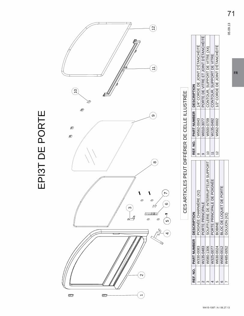
W415-1087 / A / 06.27.13
FR
71
912
11
3
10
1
8
2
56
74
912
11
3
10
1
8
2
56
74
EP
I3T
DE
PO
RTE
05.0
9.13
REF
. NO
.PA
RT
NU
MB
ERD
ESC
RIP
TIO
N1
W33
0-00
83P
OIG
NÉ
E C
HA
RN
IÉR
E (X
2)2
W13
5-04
83P
OR
TE P
RIN
CIP
ALE
3W
080-
1306
SO
UFF
LER
IE D
E IN
TER
RU
PTE
UR
SU
PP
OR
T4
W32
5-00
77P
OR
TE P
RIN
CIP
ALE
DE
PO
IGN
ÉE
5W
630-
0024
BO
BIN
E6
W06
0-00
12B
LOC
DE
LO
QU
ET
DE
PO
RTE
7W
485-
0052
GO
UJO
N (X
2)
REF
. NO
.PA
RT
NU
MB
ERD
ESC
RIP
TIO
N8
W56
2-00
431/
4" C
OR
DE
DE
JO
INT
D’É
TAN
CH
ÉIT
É9
W01
0-30
77P
OR
TE D
E V
ITR
E E
T JO
INT
D’É
TAN
CH
ÉIT
É10
W50
0-07
09C
ON
TOU
R, S
UP
PO
RT
DE
VIT
RE
(X4)
11W
135-
0492
CO
NTO
UR
, SU
PP
OR
T D
E V
ITR
E12
W56
2-00
021/
2" C
OR
DE
DE
JO
INT
D’É
TAN
CH
ÉIT
É
CE
S A
RTI
CLE
S P
EU
T D
IFFÉ
RE
R D
E C
ELL
E IL
LUS
TRÉ
E

W415-1087 / A / 06.27.13
FR
72
12
4
3
111
10
5
29
67
8
12
4
3
111
10
5
29
67
8
EP
I3C
DE
PO
RTE
(W01
0-28
55)
05.0
9.13
REF
. NO
.PA
RT
NU
MB
ERD
ESC
RIP
TIO
N1
W33
0-00
83P
OIG
NÉ
E C
HA
RN
IÉR
E (X
2)2
W13
5-04
87P
OR
TE P
RIN
CIP
ALE
3W
080-
1306
SO
UFF
LER
IE D
E IN
TER
RU
PTE
UR
SU
PP
OR
T4
W32
5-00
77P
OR
TE P
RIN
CIP
ALE
DE
PO
IGN
ÉE
5W
500-
0700
GO
UP
ILLE
DE
RE
TEN
UE
6W
630-
0024
BO
BIN
E7
W06
0-00
12B
LOC
DE
LO
QU
ET
DE
PO
RTE
REF
. NO
.PA
RT
NU
MB
ERD
ESC
RIP
TIO
N8
W48
5-00
52G
OU
JON
(X2)
9W
562-
0043
1/4"
CO
RD
E D
E J
OIN
T D
’ÉTA
NC
HÉ
ITÉ
10W
010-
3076
PO
RTE
DE
VIT
RE
ET
JOIN
T D
’ÉTA
NC
HÉ
ITÉ
11W
500-
0709
CO
NTO
UR
, SU
PP
OR
T D
E V
ITR
E (X
6)12
W56
2-00
021/
2" C
OR
DE
DE
JO
INT
D’É
TAN
CH
ÉIT
É
CE
S A
RTI
CLE
S P
EU
T D
IFFÉ
RE
R D
E C
ELL
E IL
LUS
TRÉ
E

W415-1087 / A / 06.27.13
FR
73
3
25
2427
29
31
26
3023
22
28
14
9
21
15
10
1620
19
11
1817
12
13
8
47
12
65
3
25
2427
29
31
26
3023
22
28
14
9
21
15
10
1620
19
11
1817
12
13
8
47
12
65
VU
E D
’EN
SE
MB
LE E
PI3
T
CE
S A
RTI
CLE
S P
EU
T D
IFFÉ
RE
R D
E C
ELL
E IL
LUS
TRÉ
E
05.0
9.13
REF
. NO
.PA
RT
NU
MB
ERD
ESC
RIP
TIO
N1
W13
5-04
89G
AR
NIT
UR
E D
U C
ÔTÉ
DE
LA
CO
NTO
UR
(X2)
2W
080-
1234
CR
OC
HE
TS D
U C
ON
TOU
R (X
2)3
W65
5-04
27S
UP
PO
RT
DU
CO
NTO
UR
(X2)
4W
500-
0665
SU
PP
OR
T D
U C
ON
TOU
R (C
ÔTÉ
GA
UC
HE
)5
W13
5-04
90G
AR
NIT
UR
E D
U S
OM
ME
T D
E L
A C
ON
TOU
R6
W50
0-06
42S
UP
PO
RT
DU
CO
NTO
UR
(CÔ
TÉ D
RO
ITE
)7
W01
0-28
55L’
AS
SE
MB
LAG
E D
U P
OR
TE8
W19
0-00
53C
ON
TRÔ
LE D
’AIR
9W
385-
0678
PLA
QU
E D
’HO
MO
LOG
ATIO
N10
W20
0-03
56C
OU
VE
RTU
RE
DU
SO
UFF
LER
IE11
W01
0-28
82A
SS
EM
BLA
GE
DU
SO
UFF
LER
IE12
W13
5-04
88L’
AVA
NT
DU
EP
I3T
13W
500-
0639
PLA
QU
E D
E R
ETE
NU
E (X
2)14
N57
0-00
31N
IVE
LEU
RS
(X2)
15W
715-
0916
RE
TEN
UE
DE
S B
ÛC
HE
S16
W48
5-00
47L’
ÉP
ING
LE D
E G
OU
PIL
LE F
EN
DU
E (X
4)
REF
. NO
.PA
RT
NU
MB
ERD
ESC
RIP
TIO
N17
W72
0-01
61TU
YAU
X D
’AIR
SE
CO
ND
AIR
E #
118
W72
0-01
62TU
YAU
X D
’AIR
SE
CO
ND
AIR
E #
219
W72
0-01
63TU
YAU
X D
’AIR
SE
CO
ND
AIR
E #
320
W72
0-01
64TU
YAU
X D
’AIR
SE
CO
ND
AIR
E #
421
W13
5-04
85C
ON
DU
IT D
U C
HIM
INÉ
E22
W09
0-01
95B
RIQ
UE
DE
RE
BO
RD
AVA
NT
23W
090-
0196
BR
IQU
E S
UP
ÉR
IEU
R24
W09
0-01
91B
RIQ
UE
DU
CÔ
TÉ G
AU
CH
E25
W09
0-01
94B
RIQ
UE
INFÉ
RIE
UR
ES
(CÔ
TÉ G
AU
CH
E)
26W
090-
0193
BR
IQU
E IN
FÉR
IEU
RE
S (C
ÔTÉ
DR
OIT
E)
27W
090-
0190
BR
IQU
E D
E L
’AR
RIÉ
RE
28W
090-
0192
BR
IQU
E D
U C
ÔTÉ
DR
OIT
E29
W01
8-01
33D
ÉFL
EC
TEU
R30
W36
1-01
89IS
OLA
NT
DE
CA
ISS
ON
31W
720-
0165
TUB
E D
U P
ILO
TE

W415-1087 / A / 06.27.13
FR
74
24
2326
285
25
30
22
21
27
8
14
20
11
15
7
19
1817
13
16
9
12
10
64
13
2
24
2326
285
25
30
22
21
27
8
14
20
11
15
7
19
1817
13
16
9
12
10
64
13
2
VU
E D
’EN
SE
MB
LE E
PI3
T
CE
S A
RTI
CLE
S P
EU
T D
IFFÉ
RE
R D
E C
ELL
E IL
LUS
TRÉ
E
05.0
9.13
REF
. NO
.PA
RT
NU
MB
ERD
ESC
RIP
TIO
N1
W13
5-04
94C
ON
TOU
R D
U E
PI3
T 2
W13
5-04
93C
ON
TOU
R D
U E
PI3
T3
W65
5-04
69PA
TTE
D’A
PP
UI
4W
080-
1249
SU
PP
OR
T D
E F
IXAT
ION
5W
135-
0495
CO
NTO
UR
DU
EP
I3T
6W
010-
2854
PO
RTE
DU
AS
SE
MB
LAG
E7
W20
0-03
56C
OU
VE
RTU
RE
DE
SO
UFF
LER
IE8
W38
5-06
78P
LAQ
UE
D’H
OM
OLO
GAT
ION
9W
010-
2882
AS
SE
MB
LAG
E D
U S
OU
FFLE
RIE
10W
190-
0052
CO
NTR
ÔLE
D’A
IR11
W71
5-09
16R
ETE
NU
E D
ES
BÛ
CH
ES
12W
135-
0484
L’AV
AN
T D
U E
PI3
T13
W50
0-06
41P
LAQ
UE
DE
RE
TEN
UE
(X4)
14N
570-
0031
NIV
ELE
UR
S (X
2)15
W48
5-00
47L’
ÉP
ING
LE D
E G
OU
PIL
LE F
EN
DU
E (X
4)16
W72
0-01
61TU
YAU
X D
’AIR
SE
CO
ND
AIR
E #
1
REF
. NO
.PA
RT
NU
MB
ERD
ESC
RIP
TIO
N17
W72
0-01
62TU
YAU
X D
’AIR
SE
CO
ND
AIR
E #
218
W72
0-01
63TU
YAU
X D
’AIR
SE
CO
ND
AIR
E #
319
W72
0-01
64TU
YAU
X D
’AIR
SE
CO
ND
AIR
E #
420
W13
5-04
85C
ON
DU
IT D
U C
HIM
INÉ
E21
W09
0-01
95FR
ON
T LE
DG
E B
RIC
K22
W09
0-01
96B
RIQ
UE
SU
PÉ
RIE
UR
23W
090-
0191
BR
IQU
E D
U C
ÔTÉ
GA
UC
HE
24W
090-
0194
BR
IQU
E IN
FÉR
IEU
RE
S (C
ÔTÉ
GA
UC
HE
)25
W09
0-01
93B
RIQ
UE
INFÉ
RIE
UR
ES
(CÔ
TÉ D
RO
ITE
)26
W09
0-01
90B
RIQ
UE
DE
L’A
RR
IÉR
E27
W09
0-01
92B
RIQ
UE
DU
CÔ
TÉ D
RO
ITE
28W
018-
0133
DÉ
FLE
CTE
UR
29W
361-
0189
FIR
EB
OX
INS
ULA
TIO
N30
W72
0-01
65TU
BE
DU
PIL
OTE
21
21W
090-
0195
FRO
NT
LED
GE
BR
ICK
29W
361-
0189
FIR
EB
OX
INS
ULA
TIO
N

W415-1087 / A / 06.27.13
FR
759.0 GUIDE DE DÉPANNAGE
42.14B
! AVERTISSEMENTCOUPEZ L’ALIMENTATION ÉLECTRIQUE AVANT DE PROCÉDER À L’ENTRETIEN DE L’APPAREIL.
L’APPAREIL PEUT ÊTRE CHAUD. ATTENDEZ QU’IL SOIT REFROIDI AVANT D’EN FAIRE L’ENTRETIEN.
N’UTILISEZ PAS DE PRODUITS D’ENTRETIEN ABRASIFS.
LORSQUE VOUS VÉRIFIEZ DES CONNEXIONS, QUE VOUS INSTALLEZ DES FILS DE DÉRIVATION (POUR EFFECTUER DES TESTS UNIQUEMENT) OU QUE VOUS REMPLACEZ DES COMPOSANTS, DÉBRANCHEZ L’APPAREIL DU RÉCEPTACLE AFIN D’ÉVITER LES CHOCS ÉLECTRIQUES OU DES
DOMMAGES AUX COMPOSANTS.
PROBLÈME SOLUTIONSLe feu ne s’allume pas. - Pas assez de bois d’allumage/de papier? Ajoutez-en.
- Pas assez d’air? Assurez-vous que le contrôle d’air est complètement ouvert.
- Blocage d’air froid? Brûlez un morceau de papier journal pour créer un tirage.
- Utilisez du bois bien sec. - Conduit obstrué? Inspectez la cheminée.
Présence de fumée lorsque la porte est ouverte.
- Blocage d’air froid? Brûlez un morceau de papier journal pour créer un tirage.
- Tirage insuffi sant? Ajoutez des conduits. - Laissez l’air se stabiliser avant d’ouvrir la porte. - Assurez-vous que les défl ecteurs sont bien positionnés. - Pression négative? Ouvrez une fenêtre située près de l’appareil.
Une odeur se dégage de l’appareil.
- Cuisson de la peinture. Voir la section « INSTRUCTIONS GÉNÉRALES ».
L’appareil ne devient pas suffi samment chaud.
- Le bois est trop humide. - Tirage insuffi sant? Ajoutez des conduits. - Pas assez d’air? Assurez-vous que le contrôle d’air est complètement
ouvert. Assurez-vous que le contrôle d’air n’est pas obstruée.Le bois brûle trop rapidement.
- Le contrôle d’air doit possiblement être réduit. - Assurez-vous que le couvercle de la chute à cendres est bien installé (s’il
en est muni). - Vérifi ez que le joint d’étanchéité de la porte est bien hermétique. - Le bois est peut-être extrêmement sec.
Vitre sale. - Le contrôle d’air peut être trop fermé. - Faites des feux plus chauds et plus petits. - Utilisez du bois bien sec.
La souffl erie ne fonctionne pas.
- L’appareil n’a peut-être pas atteint sa température. - Assurez-vous que la souffl erie est bien branchée.
La souffl erie ne fonc-tionne pas.
- Le protecteur contre les surcharges thermiques s’est déclenché. - Laissez l’appareil refroidir pour permettre au protecteur contre les
surcharges thermiques de se réinitialiser automatiquement.
Le mécanisme du loquet coince/grince.
- Retirez le mécanisme du bloc de loquet et lubrifi ez le ressort et les goupilles avec de la graisse, voir la section « REMPLACEMENT DU MÉCANISME DU BLOC DE LOQUET ».

W415-1087 / A / 06.27.13
FR
76 10.0 GARANTIE
NAPOLÉON® garantit ses produits contre les défauts de fabrication à l’acheteur d’origine seulement. L’enregistrement de la garantie n’est pas nécessaire. Fournissez simplement une preuve d’achat ainsi que le modèle et le numéro de série afi n d’effectuer une réclamation de garantie. L’achat doit avoir été fait par l’entremise d’un détaillant NAPOLÉON® autorisé et sous réserve des conditions et limitations suivantes :La couverture de la garantie débute à partir de la date d’installation originale.Cette garantie du fabricant n’est pas transférable et ne peut être prolongée ou étendue par aucun de nos représentants quelle qu’en soit la raison.L’appareil à bois doit être installé par un installateur ou un entrepreneur qualifi é. L’installation doit être faite conformément aux instructions d’installation incluses avec le produit et à tous les codes d’incendie et de construction locaux et nationaux.Cette garantie limitée ne couvre pas les dommages causés par un mauvais usage, un manque d’entretien, un accident, des altérations, des abus ou de la négligence, et l’installation de pièces d’autres fabricants annulera cette garantie.Cette garantie limitée ne couvre pas non plus les égratignures, le bossellement, la corrosion ou la décoloration causée par une chaleur excessive, des produits d’entretien chimiques et abrasifs ou l’écaillage des pièces en porcelaine émaillée, le bris de tout composant de ventilation utilisé dans l’installation de l’appareil.Au cours de la première année seulement, cette garantie s’étend à la réparation ou au remplacement des pièces garanties dont les matériaux ou la fabrication sont défectueux sous condition que le produit ait été utilisé conformément aux instructions de fonctionnement et dans des conditions normales.Après la première année, concernant cette Garantie à Vie Limitée du Président, NAPOLÉON® peut, à sa discrétion, se libérer entièrement de toutes obligations en ce qui concerne cette garantie en remboursant à l’acheteur d’origine le prix de gros de toute pièce garantie qui est défectueuse.Après la première année, NAPOLÉON® ne sera pas responsable de l’installation, de la main-d’oeuvre ou autres coûts ou dépenses relatives à la réinstallation d’une pièce garantie et de telles dépenses ne sont pas couvertes par cette garantie.Nonobstant toutes les dispositions contenues dans cette Garantie à Vie Limitée du Président, la responsabilité de NAPOLÉON® sous cette garantie est défi nie comme ci-dessus et elle ne s’étendra à aucun dommage accidentel consécutif ou indirect.Cette garantie défi nit l’obligation et la responsabilité de NAPOLÉON® en ce qui concerne l’appareil à bois NAPOLÉON®. Toute autre garantie énoncée ou implicite en ce qui concerne ce produit, ses composants ou accessoires est exclue.NAPOLÉON® n’endosse ni n’autorise aucun tiers à assumer en son nom toute autre responsabilité concernant la vente de ce produit. NAPOLÉON® ne sera pas responsable d’une surchauffe, des refoulements, des déversements causés par des conditions environnementales telles que des toits, des bâtiments, la proximité d’arbres, de collines, de montagnes, une ventilation ou des évents inadéquats, des confi gurations d’évacuation excessives, un apport d’air insuffi sant ou des pressions négatives qui peuvent ou non être causés par des systèmes mécaniques tels que les ventilateurs d’évacuation, les fournaises, les sèche-linge, etc.Tout dommage causé à l’appareil, à la chambre de combustion, à l’échangeur de chaleur, aux garnitures plaquées ou autres composants par l’eau, les dommages causés par les intempéries, de longues périodes d’humidité, la condensation, des produits chimiques ou produits d’entretien nuisibles ne seront pas la responsabilité de NAPOLÉON®.NAPOLÉON® se réserve le droit de demander à son représentant d’inspecter tout produit ou pièce avant d’honorer toute réclamation.Toutes les pièces remplacées en vertu de la politique de Garantie à vie limitée du Président ne peuvent faire l’objet que d’une seule réclamation. Durant les dix premières années, NAPOLÉON® remplacera ou réparera les pièces défectueuses qui sont couvertes par la garantie à vie limitée à sa discrétion gratuitement. Après les dix premières années, NAPOLÉON® fournira les pièces de rechange à 50 % du prix de détail courant.Toutes les pièces remplacées au titre de la garantie seront couvertes pour une période de 90 jours à partir de leur date d’installation.Le fabricant peut exiger que les pièces défectueuses ou les produits soient retournés ou que des photos numériques soient fournies pour valider la réclamation. Les produits retournés doivent être expédiés port payé au fabricant pour une inspection en usine. Si un produit est déclaré défectueux, le fabricant le réparera ou le remplacera. Avant d’expédier votre appareil ou les pièces défectueuses, votre détaillant doit obtenir un numéro d’autorisation. Toute marchandise expédiée à notre usine sans autorisation sera refusée et retournée à l’expéditeur.Les coûts d’expédition ne sont pas couverts par cette garantie.Des frais de service supplémentaires peuvent être appliqués si vous cherchez à obtenir des services au titre de la garantie auprès d’un détaillant. Les indemnités de main-d’oeuvre au titre de la garantie s’appliquent uniquement pour le remplacement d’une pièce garantie. Les frais de déplacement, de tests de diagnostic, d’expédition et autres frais afférents ne sont pas couverts par cette garantie.
2.2B
Les produits NAPOLÉON® sont fabriqués conformément aux normes strictes du Certifi cat d’Assurance de Qualité ISO 9001 : 2008 mondialement reconnu.
Les produits NAPOLÉON® sont conçus avec des composants et des matériaux de qualité supérieure, assemblés par des artisans qualifi és qui sont fi ers de leur travail. Une fois assemblé, chaque appareil est soigneusement inspecté par un technicien qualifi é avant d’être emballé pour garantir que vous, le client, recevez le produit de qualité dont vous vous
attendez de NAPOLÉON®.
Les matériaux suivants et la fabrication de votre nouveau poêle à bois Napoléon® sont garantis contre les défauts tant que vous en êtes le propriétaire. Ceci couvre : la chambre de combustion, l’échangeur de chaleur, la vitre en céramique (cassure thermique seulement), les pièces plaquées or contre le ternissement, les composants en porcelaine émaillée, les moulures d’extrusion en aluminium, défl ecteurs vortex, le tiroir à cendres et les pièces moulées en fonte.
Les composants électriques (110 V) et les pièces soumises à l’usure tels que la souffl erie, l’interrupteur thermique, les interrupteurs, l’installation électrique, les briques réfractaires, l’attache du défl ecteur en acier inoxydable,tuyaux d’air secondaires et les joints d’étanchéité sont couverts et Napoléon® fournira gratuitement les pièces de rechange durant la première année de la garantie limitée.
Les coûts de main-d’oeuvre relatifs aux réparations garanties sont couverts gratuitement durant la première année. Cependant, les travaux de réparation nécessitent l’approbation préalable d’un représentant autorisé de la compagnie. Les coûts de main-d’oeuvre à la charge de NAPOLÉON® sont basés sur un programme de tarifs prédéterminés et tout travail de réparation doit être accompli par l’entremise d’un détaillant autorisé NAPOLÉON®.Les pièces telles que les briques réfractaires et les défl ecteurs devraient être retirées occasionnellement par l’opérateur dans le cadre d’un entretien normal. Par conséquent, les coûts de main-d’oeuvre associés au remplacement de l’une de ces pièces ne sont pas couverts par la garantie. * La fabrication de chaque modèle varie. La garantie s’applique uniquement aux composants disponibles avec votre appareil.
GARANTIE À VIE LIMITÉE DU PRÉSIDENT DES APPAREILS À BOIS NAPOLÉON®
CONDITIONS ET LIMITATIONS
TOUTES LES SPÉCIFICATIONS ET LES CONCEPTIONS SONT SUJETTES À MODIFICATIONS SANS PRÉAVIS EN RAISON DES AMÉLIORATIONS CONSTANTES APPORTÉES AU PRODUIT. NAPOLÉON® EST UNE MARQUE DE COMMERCE DÉPOSÉE DE
WOLF STEEL LTÉE.

W415-1087 / A / 06.27.13
FR
77
Dat
e
43.1
Pro
blèm
es p
artic
ulie
rsTr
avai
l effe
ctué
Nom
du
tech
nici
enD
étai
llant
His
tori
que
d’en
tret
ien
Wol
f S
teel
Cet
app
arei
l doi
t être
ent
rete
nu a
nnue
llem
ent s
elon
son
usa
ge.
11.0 HISTORIQUE D’ENTRETIEN

W415-1087 / A / 06.27.13
FR
78
44.1
12.0 NOTES

W415-1087 / A / 06.27.13
FR
79
44.1

Autr
es
pro
duits
Napolé
on
®
Foyers encastrés • Grils au charbon de bois • Foyers au gaz • Cascades d’eau Poêles à bois • Produits HVAC • Foyers électriques • Foyers extérieurs • Grils à gaz de qualité
Foyers / Chauffage et Climatisation / Grils composez : 514-737-6294
napoleonproducts.com
7200, Route Transcanadienne, Montréal, Québec H4T 1A3
24 Napoleon Road, Barrie, Ontario, Canada L4M 0G8
214 Bayview Drive, Barrie, Ontario, Canada L4N 4Y8
103 Miller Drive, Crittenden, Kentucky, USA 41030