Embed Size (px)
Citation preview

TESTING PROTOCOL -FRONTAL IMPACT
Version 2.1 January 2017
Preface
Where text is contained within square brackets this denotes that the procedure being discussed
is currently being trialled in ASEAN NCAP. Its incorporation in the Test Protocol will be
reviewed at a later date.
During the test preparation, vehicle manufacturers are encouraged to liaise with the laboratory
and to check that they are satisfied with the way cars are set up for testing. Where a
manufacturer feels that a particular item should be altered, they should ask the laboratory staff
to make any necessary changes. Manufacturers are forbidden from making changes to any
parameter that will influence the test, such as dummy positioning, vehicle setting, laboratory
environment etc.
It is the responsibility of the test laboratory to ensure that any requested changes satisfy the
requirements of ASEAN NCAP. Where a disagreement exists between the laboratory and
manufacturer, the ASEAN NCAP secretariat should be informed immediately to pass final
judgment. Where the laboratory staff suspect that a manufacturer has interfered with any of the
setup, the manufacturer's representative should be warned that they are not allowed to do so
themselves. They should also be informed that if another incident occurs, they will be asked to
leave the test site.
Where there is a recurrence of the problem, the manufacturer’s representative will be told to
leave the test site and the Secretariat should be immediately informed. Any such incident may
be reported by the Secretariat to the manufacturer and the person concerned may not be allowed
to attend further ASEAN NCAP tests.
DISCLAIMER: ASEAN NCAP has taken all reasonable care to ensure that the information
published in this protocol is accurate and reflects the technical decisions taken by the
organisation. In the unlikely event that this protocol contains a typographical error or any other
inaccuracy, ASEAN NCAP reserves the right to make corrections and determine the
assessment and subsequent result of the affected requirement(s).
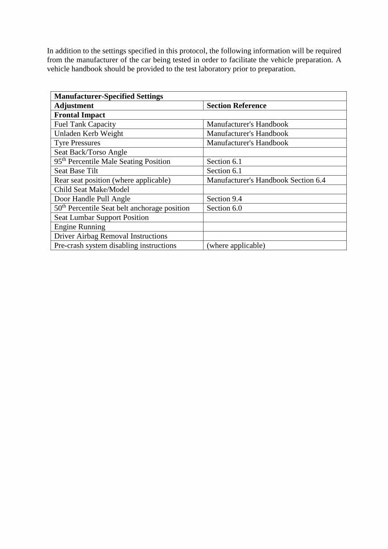
In addition to the settings specified in this protocol, the following information will be required
from the manufacturer of the car being tested in order to facilitate the vehicle preparation. A
vehicle handbook should be provided to the test laboratory prior to preparation.
Manufacturer-Specified Settings
Adjustment Section Reference
Frontal Impact
Fuel Tank Capacity Manufacturer's Handbook
Unladen Kerb Weight Manufacturer's Handbook
Tyre Pressures Manufacturer's Handbook
Seat Back/Torso Angle
95th Percentile Male Seating Position Section 6.1
Seat Base Tilt Section 6.1
Rear seat position (where applicable) Manufacturer's Handbook Section 6.4
Child Seat Make/Model
Door Handle Pull Angle Section 9.4
50th Percentile Seat belt anchorage position Section 6.0
Seat Lumbar Support Position
Engine Running
Driver Airbag Removal Instructions
Pre-crash system disabling instructions (where applicable)

Version 2.1
January 2017 4
Contents Page No.
Frontal Impact
1 VEHICLE PREPARATION 6 1.1 Unladen Kerb Mass 6 1.2 Reference Loads 6 1.3 Vehicle Width and Overlap 6 1.4 Vehicle Preparation 7
1.5 Vehicle Markings 8
2 INTRUSION MEASUREMENTS 8 2.1 Before Test 9
2.2 After Test 10
3 DUMMY PREPARATION AND CERTIFICATION 12 3.1 General 12
3.2 Dummy Certification 12 3.3 Additions and Modifications to the Hybrid III Dummies 12
3.4 Dummy Clothing and Footwear 12
3.5 Dummy Test Condition 13 3.6 Post Test Dummy Inspection 14
4 INSTRUMENTATION 15 4.1 Dummy Instrumentation 15
4.2 Vehicle Instrumentation 16
5 CAMERA LOCATIONS 18
6 PASSENGER COMPARTMENT ADJUSTMENTS 20 6.1 Determination of and Setting the Fore/aft, Tilt and Lumbar Settings of the Seat. 21 6.2 Setting the Steering Wheel Horizontal Adjustment 21
6.3 Setting the Steering Wheel Vertical Adjustment 22 6.4 Use of The Gabarit and Marking For Child Dummy Head Excursion
Measurement 22
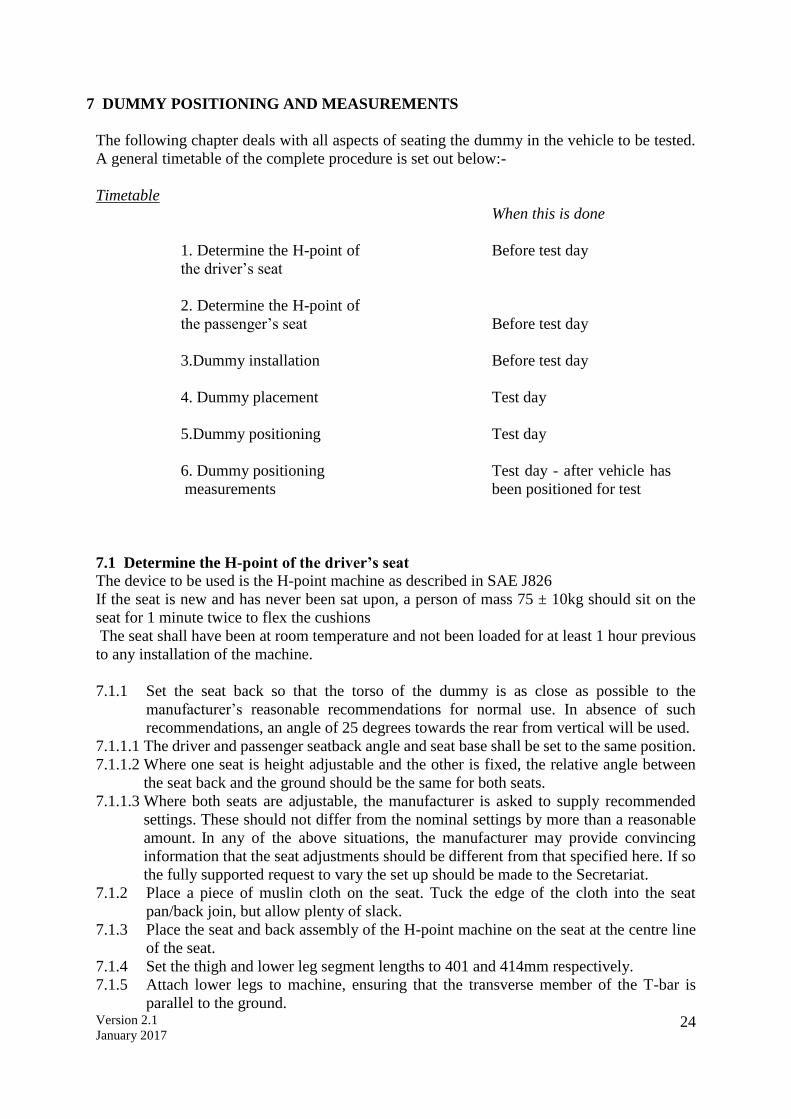
7 DUMMY POSITIONING AND MEASUREMENTS 24 7.1 Determine the H-point of the driver’s seat 24
7.2 Determine the H-point of the Passenger’s Seat 25 7.3 Dummy Installation 25 7.4 Dummy Placement 26
7.5 Dummy Positioning 26 7.6 Child Restraint System (CRS) Installation and Child Dummy Placement 28
7.7 Dummy Measurements 32
8 STILL PHOTOGRAPHY 33
9 TEST PARAMETERS 35
Version 2.1
January 2017 5
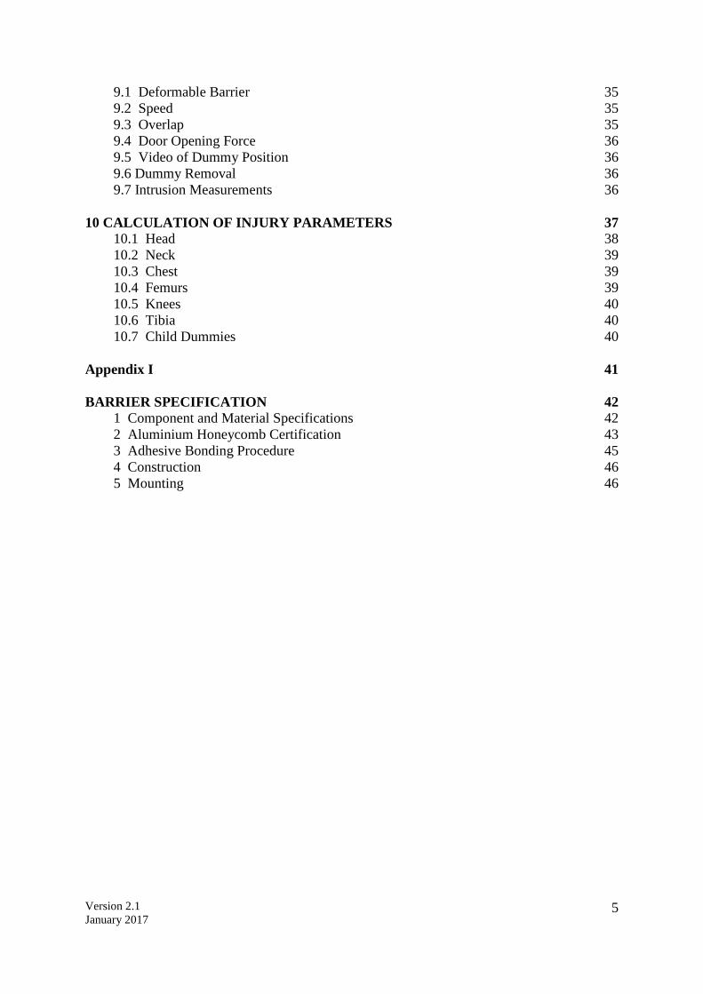
9.1 Deformable Barrier 35 9.2 Speed 35 9.3 Overlap 35 9.4 Door Opening Force 36 9.5 Video of Dummy Position 36
9.6 Dummy Removal 36 9.7 Intrusion Measurements 36
10 CALCULATION OF INJURY PARAMETERS 37 10.1 Head 38
10.2 Neck 39
10.3 Chest 39
10.4 Femurs 39 10.5 Knees 40 10.6 Tibia 40 10.7 Child Dummies 40
Appendix I 41
BARRIER SPECIFICATION 42 1 Component and Material Specifications 42
2 Aluminium Honeycomb Certification 43
3 Adhesive Bonding Procedure 45 4 Construction 46 5 Mounting 46
Version 2.1
January 2017 6
1 VEHICLE PREPARATION
1.1 Unladen Kerb Mass
1.1.1 The capacity of the fuel tank will be specified in the manufacturer’s booklet. This
volume will be referred to throughout as the “fuel tank capacity”.
1.1.2 Syphon most of the fuel from the tank and then run the car until it has run out of fuel.
1.1.3 Calculate the mass of the fuel tank capacity using a density for petrol of 0.745g/ml or
0.840g/ml for diesel. Record this figure in the test details.
1.1.4 Put water, or other ballast, to this mass in the fuel tank.
1.1.5 Check the oil level and top up to its maximum level if necessary. Similarly, top up the
levels of all other fluids to their maximum levels if necessary.
1.1.6 Ensure that the vehicle has its spare wheel on board along with any tools supplied with
the vehicle. Nothing else should be in the car.
1.1.7 Ensure that all tyres are inflated according to the manufacturer’s instructions for half
load.
1.1.8 Measure the front and rear axle weights and determine the total weight of the vehicle.
The total weight is the ‘unladen kerb mass’ of the vehicle. Record this mass in the test
details.
1.1.9 Measure and record the ride heights of the vehicle at all four wheels.
1.2 Reference Loads
1.2.1 Calculate 10 percent of the fuel tank capacity mass as determined in 1.1.3.
1.2.2 Remove this mass of ballast from the fuel tank, leaving 90 percent of the mass in the
tank.
1.2.3 Place both front seats in their mid-positions. If there is no notch at this position, set
the seat in the nearest notch rearward (this will be done more completely in Section 6).
1.2.4 Place a mass of equivalent to a Hybrid-III dummy (88kg with instrumentation and
cables) on each of the front seats.
1.2.5 Place 36kg in the luggage compartment of the vehicle. The normal luggage
compartment should be used i.e. rear seats should not be folded to increase the luggage
capacity. Spread the weights as evenly as possible over the base of the luggage
compartment. If the weights cannot be evenly distributed, concentrate weights towards
the centre of the compartment.
1.2.6 In the child restraints recommended by the manufacturer, place masses equivalent to a
3 and a 1½ year old child dummy on the rear driver seat and passenger seats
respectively (15kg and 11kg). If the child restraints are not available at this time then
default masses of 3kg should be added to the dummy masses.
1.2.7 For two seater vehicles only, the mass of child dummies and child seats shall not be
included in the reference load. For vehicles with limited rear space, child seats and
dummies shall be included in the reference load.
1.2.8 Roll the vehicle back and forth to ‘settle’ the tyres and suspension with the extra weight
on board. Weigh the front and rear axle weights of the vehicle. These loads are the
“axle reference loads” and the total weight is the “reference mass” of the vehicle.
1.2.9 Record the axle reference loads and reference mass in the test details
1.2.10 Record the ride-heights of the vehicle at the point on the wheel arch in the same
transverse plane as the wheel centres. Do this for all four wheels.
1.2.11 Remove the weights from the luggage compartment and the front and rear seats.
1.3 Vehicle Width and Overlap
1.3.1 Determine the widest point of the vehicle ignoring the rear-view mirrors, side marker

Version 2.1
January 2017 7
lamps, tyre pressure indicators, direction indicator lamps, position lamps, flexible mud-
guards and the deflected part of the tyre side-walls immediately above the point of
contact with the ground.
1.3.2 Record this width in test details.
1.3.3 Determine the centre-line of the vehicle. Calculate 10% of the vehicle width (Section
9.3) and mark a line on the bonnet and bumper which is this distance from the centre
line on the steering-wheel side of the car. The distance from this line to the widest point
on the steering wheel side of the car will be the overlap with the deformable barrier.
Take the pre-impact vehicle intrusion measurements at this point. See Section 2 for a full
description of how to do this.
1.4 Vehicle Preparation
Care should be taken during vehicle preparation that the ignition is not switched on
with the battery or airbag disconnected. This will result in an airbag warning light
coming on and the airbag system will need to be reset. The manufacturer will need to
be contacted if this occurs.
1.4.1 Ensure that the vehicle’s battery is connected to the vehicle’s electrical circuit in its
standard position. Check that the dashboard light for the airbag circuit functions as
normal. Alternatively, the vehicle battery acid may be drained or an additional live
battery may be placed in the luggage compartment of the vehicle. If the supply from
the drained battery is not supported by an additional battery, the test must be conducted
within fifteen minutes after draining the battery. Where any additional battery is used
it must be connected directly to the original battery so that the vehicle’s original
electrical system, cable routing and connections remain unaltered. The power cables
connecting both batteries must be positioned on the non-struck side of the car in such a
way to minimise the risk of the cable being cut during the impact. The cable used to
connect both batteries must have a minimum cross section of 5mm2 to ensure a
minimum voltage drop. The current supplied to the vehicle must be monitored
throughout the impact across the original battery. Where an additional battery is to be
used the vehicle manufacturer will be required to indicate the minimum voltage/current
needed during the test for all systems to operate as intended. The manufacturer will be
asked to confirm that the laboratory modifications are suitable for use in the vehicle
being tested and will not influence any of the vehicle systems.
1.4.2 In the event that the engine fluids are to be drained then drain the coolant, oil, air-
conditioning (air conditioning refrigerant should be drained without venting it to the
atmosphere) and Power Assisted Steering (PAS) fluids.
1.4.3 If the fluids are drained then measure the weights of each of these fluids, excluding the
air conditioning fluid, and replace with an equivalent weight of water or other ballast.
1.4.4 Remove the luggage area carpeting, spare wheel and any tools or jack from the car.
The spare wheel should only be removed if it will not affect the crash performance of
the vehicle.
1.4.5 An emergency abort braking system may be fitted to the vehicle. This is optional; the
test facility may elect to test without an abort system. Where such a system is fitted its
inclusion shall not influence the operation or function of any of the foot controls, in
particular the brake pedal. The position and the resistance to movement of the pedals
shall be the same as prior to fitment of the system. Remove as little as possible of the
interior trim; any mass compensation will be made when all equipment has been fitted.
1.4.6 Fit the on-board data acquisition equipment in the boot of the car. Also fit any
associated cables, cabling boxes and power sources.
Version 2.1
January 2017 8
1.4.7 Place weights equivalent to a Hybrid-III dummy (88kg) in each of the front seats of the
car (with the seats in their mid-positions).
1.4.8 In the child restraints recommended by the manufacturer, place masses equivalent to a
3 and a 1½ year old child dummy on the rear driver’s seat and passenger seat
respectively (15kg and 11kg). If the child restraints are not available at this time then
default masses of 7kg should be added to the dummy masses.
1.4.9 Weigh the front and rear axle weights of the vehicle. Compare these weights with those
determined in Section 1.2.9.
1.4.10 If the axle weights differ from those measured in Section 1.2.9 by more than 5% (of
the axle reference loads) or by more than 20kg, remove or add items which do not
influence the structural crash performance of the vehicle. Similarly, if the total vehicle
mass differs by more than 25kg from the reference mass, non-structural items may be
removed or added. The levels of ballast in the fuel tank (equivalent in mass to 90%
capacity of fuel) may also be adjusted to help achieve the desired axle weights. Any
additional mass that is added to the vehicle should be securely and rigidly attached.
1.4.11 Repeat Sections 1.4.9 and 1.4.10 until the front and rear axle weights and the total
vehicle weight are within the limits set in 1.4.10. Record the final axle weights in the
test details.
1.4.12 For fully electric vehicles, if a total vehicle mass within 25kg of the reference mass
cannot be achieved, it is acceptable for the total mass to be within 2% of the reference
mass.
1.4.13 The vehicle manufacturer will be required to inform ASEAN NCAP and the test
laboratory of the presence of any pre-crash systems that must be disabled prior to
impact. Disabling information shall be provided to the laboratory prior to impact. It is
the responsibility of the vehicle manufacturer to ensure that the disconnection of the
system does not influence the performance of any systems that are intended to function
during the impact.
1.5 Vehicle Markings
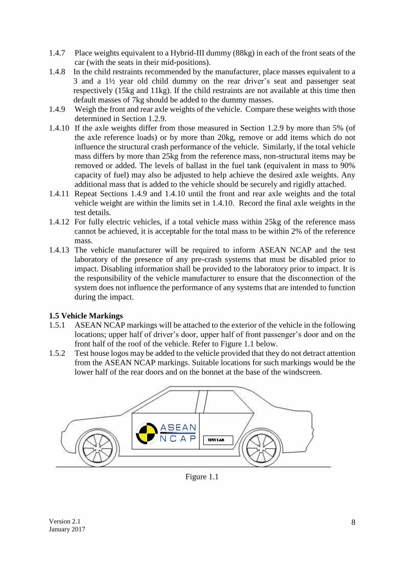
1.5.1 ASEAN NCAP markings will be attached to the exterior of the vehicle in the following
locations; upper half of driver’s door, upper half of front passenger’s door and on the
front half of the roof of the vehicle. Refer to Figure 1.1 below.
1.5.2 Test house logos may be added to the vehicle provided that they do not detract attention
from the ASEAN NCAP markings. Suitable locations for such markings would be the
lower half of the rear doors and on the bonnet at the base of the windscreen.
Figure 1.1
Version 2.1
January 2017 9
2 INTRUSION MEASUREMENTS
For vehicle deformation and intrusion measurements a 3D measuring system which is capable
of recording 3 dimensional co-ordinates of a point in space can be used. A tolerance of +/-
1mm is applicable to such a system. The system requires an axis system to be set up relative to
the object to be measured, typically the transverse, longitudinal and vertical directions of a
vehicle. An origin is first needed, followed by a point on the positive x axis and then a point
in the positive x-y plane. Since the front of the vehicle is highly deformed after the impact, it
is simplest to use some structure at the rear of the vehicle as a reference for measurement; this
obviates the need to level the car after testing, the accuracy of which is limited. Most of the
procedure which follows relates to the setting up of these axes.
2.1 Before Test
2.1.1 Determine and mark the centre of the clutch, brake and accelerator pedals.
2.1.2 Set the steering wheel to its mid-position, if it is adjustable for either rake or reach (for
full description of how to do this, see Section 6).
2.1.3 Remove the centre of the steering wheel or, if fitted, the airbag assembly to expose the
end of the steering column. When doing this, carefully note the connections to the
airbag which will need to be remade on re-assembly. Follow the manufacturer's
instructions when removing the airbag and/or steering wheel assemblies.
2.1.4 Determine and mark the centre of the top of the steering-column.
2.1.5 Remove the carpet, trim and spare wheel from the luggage compartment. The plastic
trim or rubber seals that might influence the latching mechanism should be re-fitted
once the intrusion measurements have been recorded. This is to ensure that any
opening of the rear door during the impact is not caused by the omission of some part
of the trim around the latching mechanism.
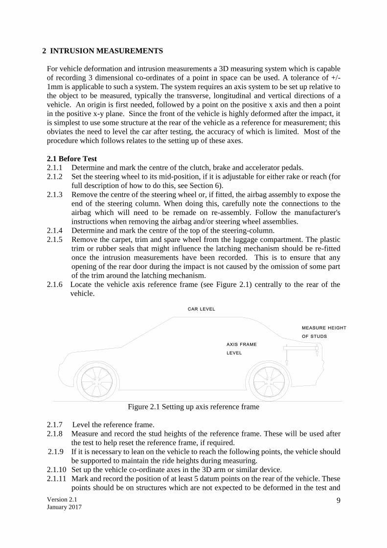
2.1.6 Locate the vehicle axis reference frame (see Figure 2.1) centrally to the rear of the
vehicle.
Figure 2.1 Setting up axis reference frame
2.1.7 Level the reference frame.
2.1.8 Measure and record the stud heights of the reference frame. These will be used after
the test to help reset the reference frame, if required.
2.1.9 If it is necessary to lean on the vehicle to reach the following points, the vehicle should
be supported to maintain the ride heights during measuring.
2.1.10 Set up the vehicle co-ordinate axes in the 3D arm or similar device.
2.1.11 Mark and record the position of at least 5 datum points on the rear of the vehicle. These
points should be on structures which are not expected to be deformed in the test and
Version 2.1
January 2017 10
should be positioned such that they have wide spaced locations in three dimensions and
can all be reached with the 3D measuring system in one position.
2.1.12 Working on the passenger side of the vehicle determine and mark the positions on the
B-post which are: i) at a distance of 100 mm above the sill.
ii) at a distance of 100 mm beneath the lowest level of the side
window aperture.
All points should be as close as possible to the rubber sealing strip around the door
aperture.
2.1.13 Measure and record the pre-impact positions of the two door aperture points.
2.1.14 Working on the driver’s side of the vehicle determine and mark the positions on the A
and B posts which are: i) at a distance of 100 mm above the sill.
ii) at a distance of 100 mm beneath the lowest level of the side
window aperture.
All points should be as close as possible to the rubber sealing strip around the door
aperture.
2.1.15 Use the arm to measure the pre-impact positions of the centre of the top of the steering-
column and the four door aperture points.
2.1.16 Record the position of the centre of the un-depressed clutch, brake and accelerator
pedals and where applicable foot operated parking brake. If the pedal is adjustable, set
it to the mid position or a reasonable variation from this in accordance with the
manufacturer’s recommendations for the 50th percentile position.
2.1.17 Replace the steering wheel and airbag assembly. Check that all bolts are securely
fastened. Ensure that all connections to the airbag are replaced and check the dashboard
light to confirm the circuit is functional.
2.2 After Test
2.2.1 Before dummy removal measure the distance between all foot pedals and a fixed point
in the footwell e.g. seat runner, seat mounting bolt. If access cannot be gained remove
the dummies, according to Section 9.6, taking care not to disturb any pedals and then
record the measurement. This measurement should be re-checked before the pedals
are measured with the 3D measuring system. If the pedal has moved re-position the
pedal using the measurement taken previously.
2.2.2 Remove the dummies according to Section 9.6 and remove the data acquisition and
emergency abort equipment (if fitted) from the luggage compartment.
2.2.3 Remove the centre of the steering wheel or airbag assembly.
2.2.4 Use any 3 of the 5 datum points at the rear of the vehicle, and their pre-impact
measurements, to redefine the measurement axes.
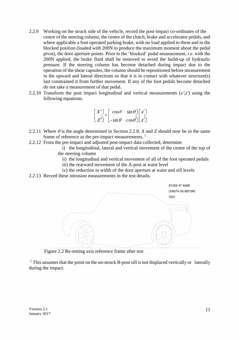
2.2.5 If the axes cannot be redefined from any 3 of the datum points relocate the axis
reference frame in the same position as in Section 2.1.8. Set the studs of the frame to
the same heights as in Section 2.1.11 (Figure 2.2). The frame should now be in the
same position relative to the car as it was before impact. Set up the measurement axes
from the frame.
2.2.6 Record the post-impact positions of the B-post points on the unstruck passenger’s side
of the vehicle.
2.2.7 Compare the vertical co-ordinate of the B-post sill point before (Section 2.1.12) and
after (Section 2.2.5) the test.
2.2.8 Find the angle that best satisfies the following equation: z = - xsin + zcosfor the
B-post sill point (where z = pre impact vertical measurement and x,z = post-impact
longitudinal and vertical).
Version 2.1
January 2017 11
2.2.9 Working on the struck side of the vehicle, record the post-impact co-ordinates of the
centre of the steering column, the centre of the clutch, brake and accelerator pedals, and
where applicable a foot operated parking brake, with no load applied to them and in the
blocked position (loaded with 200N to produce the maximum moment about the pedal
pivot), the door aperture points. Prior to the ‘blocked’ pedal measurement, i.e. with the
200N applied, the brake fluid shall be removed to avoid the build-up of hydraulic
pressure. If the steering column has become detached during impact due to the
operation of the shear capsules, the column should be repositioned before measurement
in the upward and lateral directions so that it is in contact with whatever structure(s)
last constrained it from further movement. If any of the foot pedals become detached
do not take a measurement of that pedal.
2.2.10 Transform the post impact longitudinal and vertical measurements (x,z) using the
following equations.
2.2.11 Where is the angle determined in Section 2.2.8. X and Z should now be in the same
frame of reference as the pre-impact measurements. 1
2.2.12 From the pre-impact and adjusted post-impact data collected, determine
i) the longitudinal, lateral and vertical movement of the centre of the top of
the steering column
ii) the longitudinal and vertical movement of all of the foot operated pedals
iii) the rearward movement of the A-post at waist level
iv) the reduction in width of the door aperture at waist and sill levels
2.2.13 Record these intrusion measurements in the test details.
Figure 2.2 Re-setting axis reference frame after test
1 This assumes that the point on the un-struck B-post sill is not displaced vertically or laterally
during the impact.
z
x
-
θ =
Z
X
cossin
sincos

Version 2.1
January 2017 12
3 DUMMY PREPARATION AND CERTIFICATION
3.1 General
3.1.1 Hybrid III test dummies should be used for the front seat driver and passenger
positions. They should conform to U.S. Department of transportation, Code of Federal
Regulations Part 572 Subpart E and ECE Regulation No. 94, except for modifications
and additions stated later - See Section 3.3.
3.1.2 A Q1½ child dummy, in a suitable Child Restraint System (CRS) (see Section 7.6),
shall be used in the rear passenger side seating position.
3.1.3 A Q3 child dummy, in a suitable CRS (see Section 7.6), shall be used in the rear driver’s
side seating position.
3.2 Dummy Certification
Full details of the certification procedure for the Hybrid-III dummy are available elsewhere
(see Part 572 Subpart E of US Department of Transportation Code of Federal Regulations),
SAE J2856 and Annex 10 of ECE Regulation No. 94). Details of the certification procedure
of the Q1½ and Q3 child dummies are available in the user documentation. No manufacturer
shall have access to any pre-test information regarding any of the test equipment to be used by
ASEAN NCAP, or be permitted to influence its selection in any way.
3.2.1 The Hybrid-III dummies shall be re-certified after every THREE impact tests.
3.2.2 The chest shall be certified according to the frequency above and should meet both the
low speed thorax test as prescribed by SAE J2779, as well as the full certification test
detailed in CFR572. Additionally, chest potentiometer calibration and polynomial post
processing shall also be performed as detailed in SAE J2517. See Technical Bulletin
005 for more details.
3.2.3 The knee slider shall be certified to SAE J2867 after every THREE impact tests and as
specified in SAE J2856 after every NINE impact tests. See Technical Bulletin 006 for
more details.
3.2.5 If an injury criterion reaches or exceeds its normally accepted limit (eg HIC of 700)
then that part of the dummy shall be re-certified.
3.2.6 If any part of a dummy is broken in a test then the part shall be replaced with a fully
certified component.
3.2.7 Copies of the dummy certification certificates will be provided as part of the full report
for a test.
3.3 Additions and Modifications to the Hybrid III Dummies
3.3.1 The additions and modifications which will change the dynamic behaviour of the test
dummies from Part 572E specification dummies are:
3.3.2 Roller ball-bearing knees shall be fitted.
3.3.3 Extra instrumentation is also fitted such as enhanced instrumented lower legs and a 6-
axis neck. See Section 4 for a full instrumentation list.
3.3.4 Foam neck shields (Part 93051-1-DN or equivalent) must be fitted to the driver and
passenger if a frontal protection airbag is present.
3.4 Dummy Clothing and Footwear
3.4.1 Hybrid-III dummies
3.4.1.1 Each dummy will be clothed with formfitting cotton stretch garments with short sleeves
and pants which should not cover the dummy’s knees.
3.4.1.2 Each dummy shall be fitted with shoes equivalent to those specified in MIL-S13192 rev
P. (size XW)
Version 2.1
January 2017 13
3.4.2 Child Dummies
3.4.2.1 Each child dummy shall wear their appropriate suits, Q3 part number 020-8000, Q1½
part number 048-8000.
3.5 Dummy Test Condition
3.5.1 Dummy Temperature
3.5.1.1 The dummy shall have a stabilised temperature in the range of 19oC to 22oC.
3.5.1.2 A stabilised temperature shall be obtained by soaking the dummy in temperatures that
are within the range specified above for at least 5 hours prior to the test.
3.5.1.3 Measure the temperature of the dummy using a recording electronic thermometer
placed inside the dummy’s flesh. The temperature should be recorded at intervals not
exceeding 10 minutes.
3.5.1.4 A printout of the temperature readings is to be supplied as part of the standard output
of the test.
3.5.2 Dummy Joints
All constant friction joints should have their ‘stiffness’ set by the following method
3.5.2.1 Stabilise the dummy temperature by soaking in the required temperature range for at
least 5hours.
3.5.2.2 The tensioning screw or bolt which acts on the constant friction surfaces should be
adjusted until the joint can just hold the adjoining limb in the horizontal. When a small
downward force is applied and then removed, the limb should continue to fall.
3.5.2.3 The dummy joint stiffness should be set as close as possible to the time of the test and,
in any case, not more than 24 hours before the test.
3.5.2.4 Maintain the dummy temperature within the range 19 to 22C between the time of
setting the limbs and up to a maximum of 10 minutes before the time of the test.
3.5.3 Dummy face painting
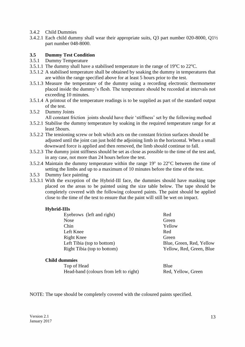
3.5.3.1 With the exception of the Hybrid-III face, the dummies should have masking tape
placed on the areas to be painted using the size table below. The tape should be
completely covered with the following coloured paints. The paint should be applied
close to the time of the test to ensure that the paint will still be wet on impact.
Hybrid-IIIs Eyebrows (left and right) Red
Nose Green
Chin Yellow
Left Knee Red
Right Knee Green
Left Tibia (top to bottom) Blue, Green, Red, Yellow
Right Tibia (top to bottom) Yellow, Red, Green, Blue
Child dummies Top of Head Blue
Head-band (colours from left to right) Red, Yellow, Green
NOTE: The tape should be completely covered with the coloured paints specified.

Version 2.1
January 2017 14
Paint Area Sizes:
Hybrid-IIIs
Eyebrows = (25/2) x 50mm
Nose = 25 x 40mm strip, down nose centre line
Chin = 25 x 25mm square, centre line of chin
Knees = 50 x 50mm square, knee centre line with bottom edge level with top
of tibia flesh
Tibias = 25mm x 50mm, 4 adjacent areas down leg centre line with top edge
level with top of tibia flesh
Child Dummies
Top of Head = 50 x 50mm square
Headbands = 25mm wide, widest circumference remaining at eyebrow level at front,
extending to the head C of G at each side.
3.6 Post Test Dummy Inspection
3.6.1 The dummies should be visually inspected immediately after the test. Any lacerations
of the skin or breakages of a dummy should be noted in the test specification. A dummy
may have to be re-certified in this case. Refer to Section 3.2.

Version 2.1
January 2017 15
4 INSTRUMENTATION
All instrumentation shall be calibrated before the test programme. The Channel Amplitude
Class (CAC) for each transducer shall be chosen to cover the Minimum Amplitude listed in the
table. In order to retain sensitivity, CACs which are orders of magnitude greater than the
Minimum Amplitude should not be used. A transducer shall be re-calibrated if it reaches its
CAC during any test. All instrumentation shall be re-calibrated after one year, regardless of
the number of tests for which it has been used. A list of instrumentation along with calibration
dates should be supplied as part of the standard results of the test. The transducers are mounted
according to procedures laid out in SAE J211 (1995). The sign convention used for configuring
the transducers is stated in SAE J211.
4.1 Dummy Instrumentation
The dummies to be used shall be instrumented to record the channels listed below.
Hybrid-III Location
Parameter
Minimum
Amplitude
Driver No of
channels
Passenger No of
channels Head
Accelerations, Ax Ay Az
250g
3
3
Neck
Forces
Fx Fy
9kN
2
2
Fz
14kN
1
1
Moments, Mx My Mz
290Nm
3
3
Chest
Accelerations, Ax Ay Az
150g
3
3
Deflection, Dchest
100mm
1
1
Pelvis
Accelerations, Ax Ay Az
150g
3
3
Femurs (L & R)
Forces, Fz
20kN
2
2
Knees (L & R)
Displacements, Dknee
19mm
2
2
Upper Tibia
(L & R)
Forces, Fx Fz
12kN
4
4
Moments, Mx My
400Nm
4
4
Lower Tibia2
(L & R)
Forces, Fx Fz (Fy)
12kN
4
4
Moments, Mx My
400Nm
4
4
Total Channels per Dummy
36
36
Total Channels
72
2 Note that for both dummies the measurement of Fy is at the laboratory’s discretion.
Version 2.1
January 2017 16
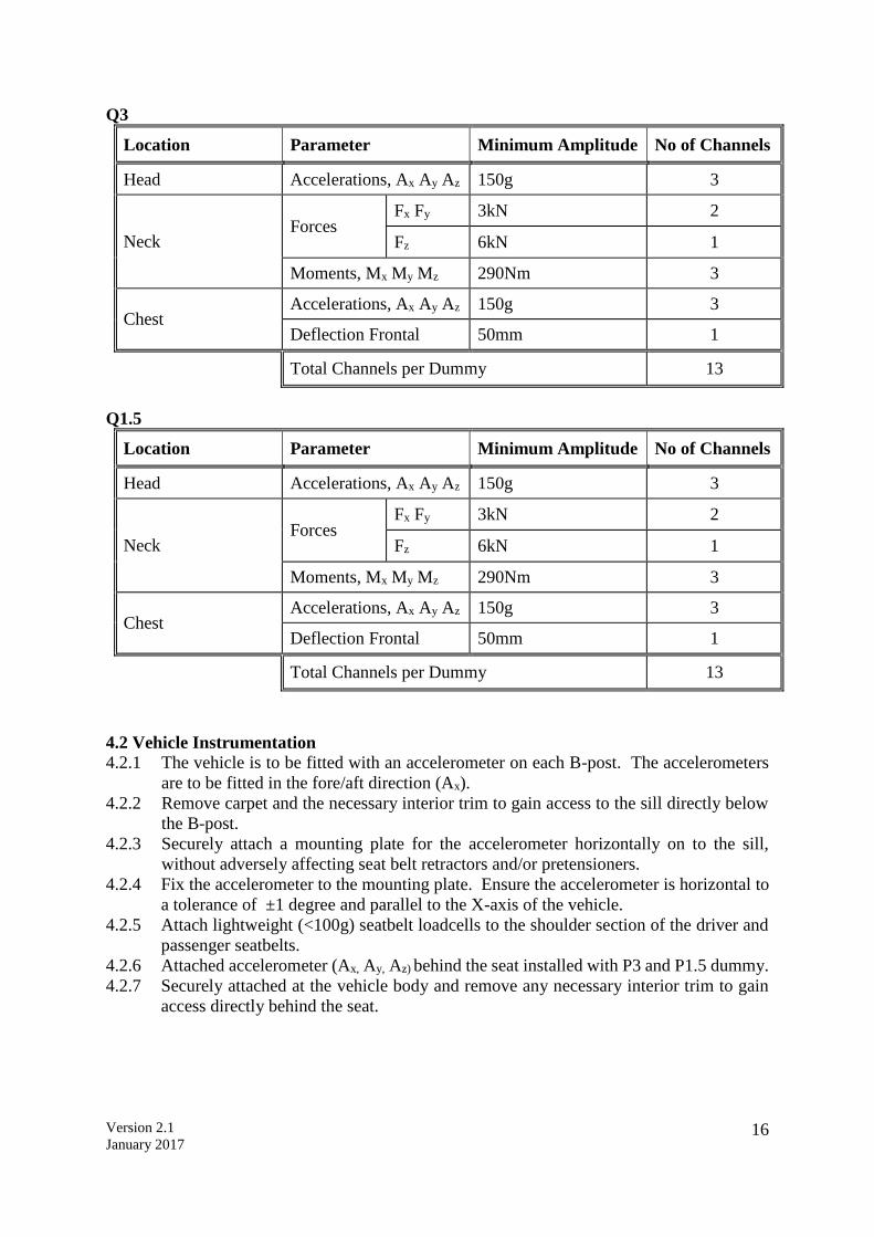
Q3
Location Parameter Minimum Amplitude No of Channels
Head Accelerations, Ax Ay Az 150g 3
Neck Forces
Fx Fy 3kN 2
Fz 6kN 1
Moments, Mx My Mz 290Nm 3
Chest Accelerations, Ax Ay Az 150g 3
Deflection Frontal 50mm 1
Total Channels per Dummy 13
Q1.5
Location Parameter Minimum Amplitude No of Channels
Head Accelerations, Ax Ay Az 150g 3
Neck Forces
Fx Fy 3kN 2
Fz 6kN 1
Moments, Mx My Mz 290Nm 3
Chest Accelerations, Ax Ay Az 150g 3
Deflection Frontal 50mm 1
Total Channels per Dummy 13
4.2 Vehicle Instrumentation
4.2.1 The vehicle is to be fitted with an accelerometer on each B-post. The accelerometers
are to be fitted in the fore/aft direction (Ax).
4.2.2 Remove carpet and the necessary interior trim to gain access to the sill directly below
the B-post.
4.2.3 Securely attach a mounting plate for the accelerometer horizontally on to the sill,
without adversely affecting seat belt retractors and/or pretensioners.
4.2.4 Fix the accelerometer to the mounting plate. Ensure the accelerometer is horizontal to
a tolerance of ±1 degree and parallel to the X-axis of the vehicle.
4.2.5 Attach lightweight (<100g) seatbelt loadcells to the shoulder section of the driver and
passenger seatbelts.
4.2.6 Attached accelerometer (Ax, Ay, Az) behind the seat installed with P3 and P1.5 dummy.
4.2.7 Securely attached at the vehicle body and remove any necessary interior trim to gain
access directly behind the seat.
Version 2.1
January 2017 17
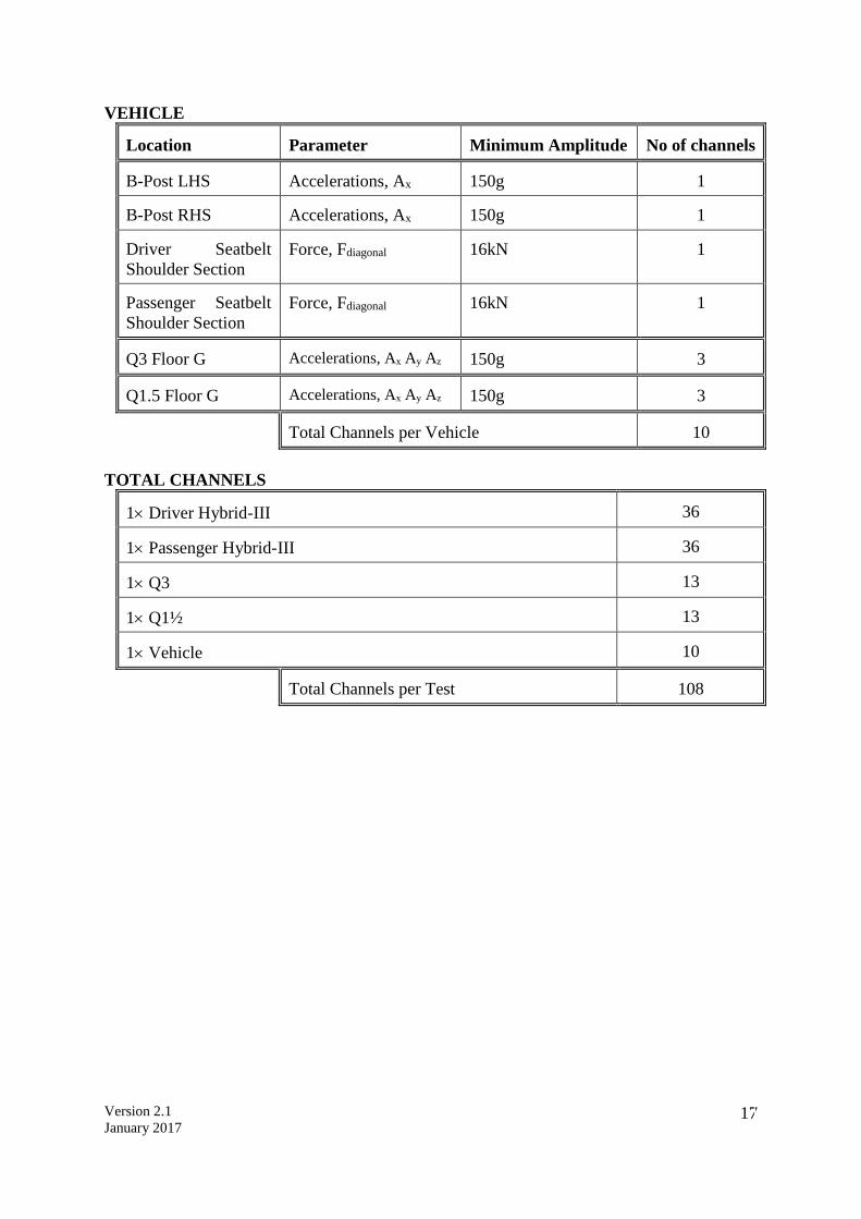
VEHICLE Location
Parameter
Minimum Amplitude
No of channels
B-Post LHS
Accelerations, Ax
150g
1
B-Post RHS
Accelerations, Ax
150g
1
Driver Seatbelt
Shoulder Section
Force, Fdiagonal
16kN
1
Passenger Seatbelt
Shoulder Section
Force, Fdiagonal
16kN
1
Q3 Floor G
Accelerations, Ax Ay Az
150g
3
Q1.5 Floor G
Accelerations, Ax Ay Az
150g
3
Total Channels per Vehicle
10
TOTAL CHANNELS 1 Driver Hybrid-III
36
1 Passenger Hybrid-III
36
1 Q3
13
1 Q1½
13
1 Vehicle
10
Total Channels per Test
108
Version 2.1
January 2017 18
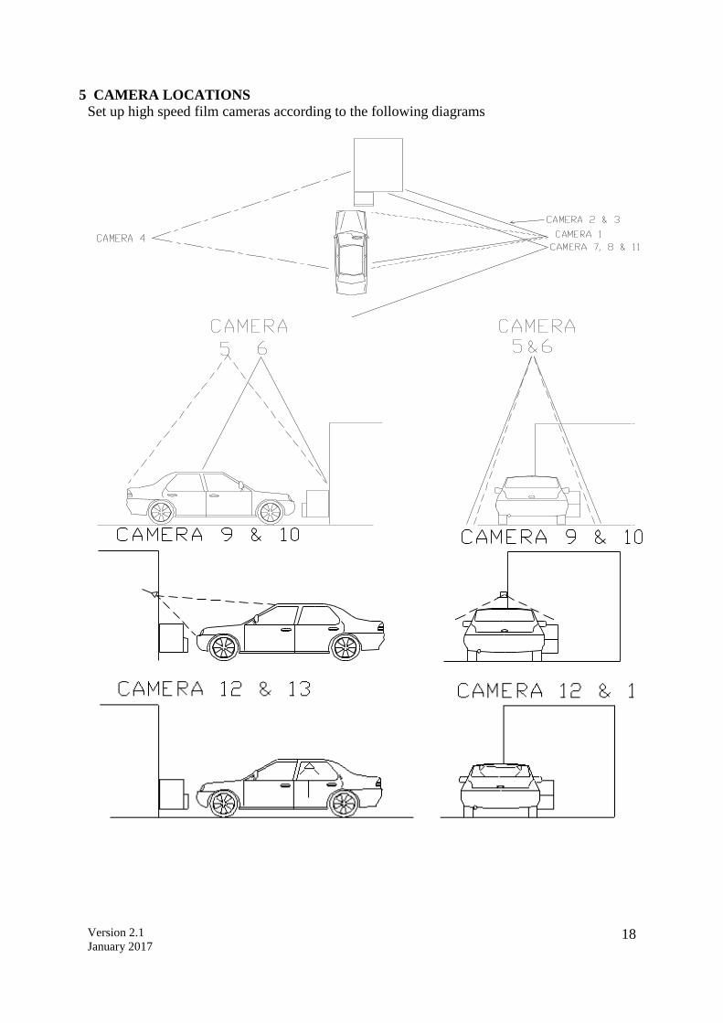
5 CAMERA LOCATIONS
Set up high speed film cameras according to the following diagrams
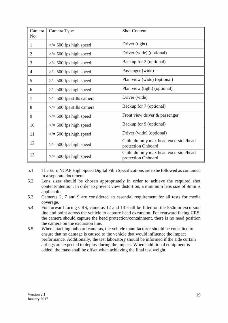
Version 2.1
January 2017 19
Camera
No.
Camera Type Shot Content
1
>/= 500 fps high speed Driver (tight)
2
>/= 500 fps high speed Driver (wide) (optional)
3
>/= 500 fps high speed Backup for 2 (optional)
4
>/= 500 fps high speed Passenger (wide)
5
>/= 500 fps high speed Plan view (wide) (optional)
6
>/= 500 fps high speed Plan view (tight) (optional)
7
>/= 500 fps stills camera Driver (wide)
8
>/= 500 fps stills camera Backup for 7 (optional)
9
>/= 500 fps high speed Front view driver & passenger
10
>/= 500 fps high speed Backup for 9 (optional)
11
>/= 500 fps high speed Driver (wide) (optional)
12
>/= 500 fps high speed
Child dummy max head excursion/head
protection Onboard 13
>/= 500 fps high speed
Child dummy max head excursion/head
protection Onboard
5.1 The Euro NCAP High Speed Digital Film Specifications are to be followed as contained
in a separate document.
5.2 Lens sizes should be chosen appropriately in order to achieve the required shot
content/intention. In order to prevent view distortion, a minimum lens size of 9mm is
applicable.
5.3 Cameras 2, 7 and 9 are considered an essential requirement for all tests for media
coverage.
5.4 For forward facing CRS, cameras 12 and 13 shall be fitted on the 550mm excursion
line and point across the vehicle to capture head excursion. For rearward facing CRS,
the camera should capture the head protection/containment, there is no need position
the camera on the excursion line.
5.5 When attaching onboard cameras, the vehicle manufacturer should be consulted to
ensure that no damage is caused to the vehicle that would influence the impact
performance. Additionally, the test laboratory should be informed if the side curtain
airbags are expected to deploy during the impact. Where additional equipment is
added, the mass shall be offset when achieving the final test weight.
Version 2.1
January 2017 20
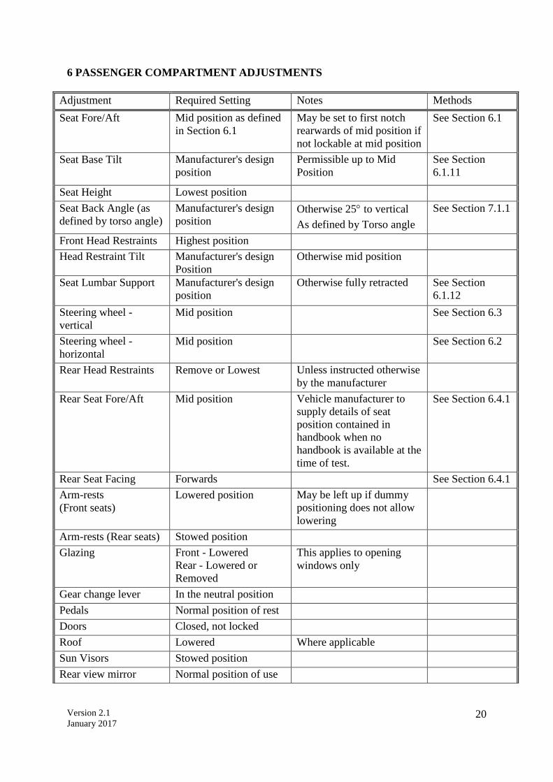
6 PASSENGER COMPARTMENT ADJUSTMENTS
Adjustment Required Setting Notes Methods
Seat Fore/Aft Mid position as defined
in Section 6.1
May be set to first notch
rearwards of mid position if
not lockable at mid position
See Section 6.1
Seat Base Tilt Manufacturer's design
position
Permissible up to Mid
Position
See Section
6.1.11
Seat Height Lowest position
Seat Back Angle (as
defined by torso angle)
Manufacturer's design
position Otherwise 25 to vertical
As defined by Torso angle
See Section 7.1.1
Front Head Restraints Highest position
Head Restraint Tilt
Manufacturer's design
Position
Otherwise mid position
Seat Lumbar Support Manufacturer's design
position
Otherwise fully retracted See Section
6.1.12
Steering wheel -
vertical
Mid position See Section 6.3
Steering wheel -
horizontal
Mid position See Section 6.2
Rear Head Restraints Remove or Lowest Unless instructed otherwise
by the manufacturer
Rear Seat Fore/Aft Mid position Vehicle manufacturer to
supply details of seat
position contained in
handbook when no
handbook is available at the
time of test.
See Section 6.4.1
Rear Seat Facing Forwards See Section 6.4.1
Arm-rests
(Front seats)
Lowered position May be left up if dummy
positioning does not allow
lowering
Arm-rests (Rear seats) Stowed position
Glazing Front - Lowered
Rear - Lowered or
Removed
This applies to opening
windows only
Gear change lever In the neutral position
Pedals Normal position of rest
Doors Closed, not locked
Roof Lowered Where applicable
Sun Visors Stowed position
Rear view mirror Normal position of use

Version 2.1
January 2017 21
Seat belt anchorage
(where adjustable)
Initially, manufacturer’s
50th percentile design
position
If no design position then
set to mid-position, or
nearest notch upwards
Adjustments not listed will be set to mid-positions or nearest positions rearward, lower or outboard.
6.1 Determination of and Setting the Fore/aft, Tilt and Lumbar Settings of the Seat.
6.1.1 The manufacturers seat fore/aft position which corresponds to the 95th percentile male
seating position will have been provided.
6.1.2 Place a mark on the moving part of seat runner close to the unmoving seat guide.
6.1.3 Move the seat to its most forward position of travel.
6.1.4 Mark the unmoving seat guide in line with the mark on the seat runner. This
corresponds to the seat in its most forward position.
6.1.5 Move the seat to the position of its travel provided for the 95th percentile male.
6.1.6 Mark the unmoving seat guide in line with the mark on the seat runner. This
corresponds to the 95th percentile male’s seating position.
6.1.7 Measure the distance between the forwards and rearwards marks. Place a third mark
on the seat guide mid-way between the forwards and rearwards marks.
6.1.8 Move the seat so that the mark on the seat runner aligns with the mark on the seat guide.
6.1.9 Lock the seat at this position. Ensure that the seat is fully latched in its runners on both
sides of the seat. The seat is now defined as being at its ‘mid seating position’. The
vehicle will be tested with the seat in this position.
6.1.10 If the seat will not lock in this position, move the seat to the first locking position that
is rear of the mid seating position. The vehicle will be tested with the seat in this
position.
6.1.11 If the seat base is adjustable for tilt it may be set to any angle from the flattest up to its
mid position according to the manufacturer’s preference. The same seat tilt setting must
be used for frontal and side impact.
6.1.12 If the seat back is adjustable for lumbar support it should be set to the fully retracted
position, unless the manufacturer specifies otherwise or the dummy prevents this.
6.2 Setting the Steering Wheel Horizontal Adjustment
6.2.1 Choose a part of the facia that is adjacent to the steering column and can be used as a
reference.
6.2.2 Move the steering wheel to the most forward position of its travel
6.2.3 Mark the steering column in line with an unmoving part of the facia. This corresponds
to the most forward travel of the steering wheel.
6.2.4 Move the steering wheel to the most rearwards position of its travel
6.2.5 Mark the steering column in line with an unmoving part of the facia. This corresponds
to the most rearwards travel of the steering wheel.
6.2.6 Measure the distance between the forwards and rearwards marks on the steering
column. Place a third mark on the steering column mid-way between the forwards and
rearwards marks. This corresponds to the centre of travel of the steering wheel.
6.2.7 Move the steering wheel so that the mark on the steering column aligns with the facia.
6.2.8 Lock the steering column at this position. The steering wheel is now in its mid-position
of travel. The vehicle will be tested with the steering wheel in this position.
Version 2.1
January 2017 22
6.3 Setting the Steering Wheel Vertical Adjustment
A method that is in principle the same as Section 6.2 should be used to determine and set the
steering wheel vertical adjustment to the mid position.
It is unlikely that the same part of the facia used during the setting procedures for the horizontal
adjustments could be used for the vertical adjustment.
Care should be taken to avoid unintentional adjustment of the horizontal setting during the
vertical adjustment procedure.
6.4 Use of The Gabarit and Marking For Child Dummy Head Excursion Measurement
A device known as a Gabarit (as defined in ECE Regulation 16) is used to check the
compatibility of the vehicle with ECE Regulation 44.03 Universal child restraints. This device
is used to check the following;
i) the position of the buckle tongue stop on the adult seat belt to ensure compatibility
with all types of child restraint.
ii) the length of the adult seat belt webbing compared to the requirement of Universal
restraints for those seats designated as suitable for such restraints.
iii) and the position of the adult seat belt hardware relative to the belt contact zones
specified for universal child restraints.
Position the Gabarit in all seating positions within the vehicle, excluding the driver’s, as
specified in ECE Regulation 16. Photographs of the installation, and in particular, the position
of the lap section of the belt (both sides) and buckle tongue slot in relation to the 150mm radius
shall be taken. The position of the base of the Gabarit relative to the front of the car seat base
cushion should also be photographed for each seating position examined. The photograph
should be taken from a point in a horizontal plane passing through the top of the car seat base
cushion, to illustrate if there is an air gap between the gabarit base and car seat base cushion
and any other indication of insufficient belt webbing.
The test laboratory shall specify in the test report whether the three point seat belts fitted to the
vehicle are in accordance with ECE Regulation 16, Section 8.2.2.5.
This assessment will be done in accordance with ECE Regulation 16 Annex 13. The vehicle
handbook will be checked for guidance about which seat positions in the vehicle are suitable
for use with Universal child restraints and which seat positions are unsuitable for use by
children. In addition the Cr point within the vehicle will be defined by use of the Gabarit.
6.4.1 If the vehicle rear seat position is adjustable put it in the mid position of its horizontal
adjustment range, unless the manufacturer’s handbook says otherwise when using child
seats, and adjust the seat back angle in accordance with the procedure in 7.1. If the
direction of facing of the seat is adjustable it should be set to face forward, with its axis
parallel to the fore/aft direction of the vehicle.
6.4.2 If the adult seat belt has an adjustable upper anchorage set the anchorage in the lowest
position unless permanently attached instructions on the child restraint or vehicle
suggest otherwise.
6.4.3 With the Gabarit positioned as specified in ECE Regulation 16, the positions of the
back and bottom planes of the device will be defined using the 3D Measuring arm,
targets will be applied to the top and side surfaces of the Gabarit to help in this process.
The intersection of these planes will define the Cr point for the seating position in
question. The Cr point is needed to give a reference point for head excursion
measurement on the dummy.
Version 2.1
January 2017 23
6.4.4 The vehicle should be clearly marked to define a scale of at least 400-600mm (50mm
increments) forward of the Cr point. The intention is that these marks should be clearly
visible on the high speed film. The camera views should be set to try to minimise
parallax error when viewing the dummy head at full excursion relative to the defined
scales. Marking should be applied to the exterior top and waist level of the door as well
as inside the car at waist level. Having noted the scale points that are aligned at full
excursion from the high speed film, the same points will be identified on the car
statically after test. The points will be joined by a straight line and the dummy forward
excursion deduced by considering the forward excursion indicated at the mid line of
the seating position in question.
6.4.5 The 550mm excursion line shall be clearly distinguished from the other markings in
some way, for example using a different colour. This line shall also be marked on the
vehicle in locations that are clearly visible to the onboard cameras. Alternatively, it is
acceptable for the line across the vehicle to be superimposed during post film
processing.
Version 2.1
January 2017 24
7 DUMMY POSITIONING AND MEASUREMENTS
The following chapter deals with all aspects of seating the dummy in the vehicle to be tested.
A general timetable of the complete procedure is set out below:-
Timetable
1. Determine the H-point of
the driver’s seat
2. Determine the H-point of
the passenger’s seat
3.Dummy installation
4. Dummy placement
5.Dummy positioning
6. Dummy positioning
measurements
When this is done
Before test day
Before test day
Before test day
Test day
Test day
Test day - after vehicle has
been positioned for test
7.1 Determine the H-point of the driver’s seat
The device to be used is the H-point machine as described in SAE J826
If the seat is new and has never been sat upon, a person of mass 75 ± 10kg should sit on the
seat for 1 minute twice to flex the cushions
The seat shall have been at room temperature and not been loaded for at least 1 hour previous
to any installation of the machine.
7.1.1 Set the seat back so that the torso of the dummy is as close as possible to the
manufacturer’s reasonable recommendations for normal use. In absence of such
recommendations, an angle of 25 degrees towards the rear from vertical will be used.
7.1.1.1 The driver and passenger seatback angle and seat base shall be set to the same position.
7.1.1.2 Where one seat is height adjustable and the other is fixed, the relative angle between
the seat back and the ground should be the same for both seats.
7.1.1.3 Where both seats are adjustable, the manufacturer is asked to supply recommended
settings. These should not differ from the nominal settings by more than a reasonable
amount. In any of the above situations, the manufacturer may provide convincing
information that the seat adjustments should be different from that specified here. If so
the fully supported request to vary the set up should be made to the Secretariat.
7.1.2 Place a piece of muslin cloth on the seat. Tuck the edge of the cloth into the seat
pan/back join, but allow plenty of slack.
7.1.3 Place the seat and back assembly of the H-point machine on the seat at the centre line
of the seat.
7.1.4 Set the thigh and lower leg segment lengths to 401 and 414mm respectively.
7.1.5 Attach lower legs to machine, ensuring that the transverse member of the T-bar is
parallel to the ground.

Version 2.1
January 2017 25
7.1.6 Place right foot on undepressed accelerator pedal, with the heel as far forwards as
allowable. The distance from the centre line of the machine should be noted.
7.1.7 Place left foot at equal distance from centre line of machine as the right leg is from
centre line. Place foot flat on footwell.
7.1.8 Apply lower leg and thigh weights.
7.1.9 Tilt the back pan forwards to the end stop and draw the machine away from the seat-
back.
7.1.10 Allow the machine to slide back until it is stopped by contacting the seat back.
7.1.11 Apply a 10kg load twice to the back and pan assembly positioned at the intersection of
the hip angle intersection to a point just above the thigh bar housing.
7.1.12 Return the machine back to the seat back.
7.1.13 Install the right and left buttock weights.
7.1.14 Apply the torso weights alternately left and right.
7.1.15 Tilt the machine back forwards to the end stop and rock the pan by 5 degrees either
side of the vertical. The feet are NOT to be restrained during the rocking. After rocking
the T-bar should be parallel to the ground.
7.1.16 Reposition the feet by lifting the leg and then lowering the leg so that the heel contacts
the floor and the sole lies on the undepressed accelerator pedal.
7.1.17 Return the machine back to the seat back.
7.1.18 Check the lateral spirit level and if necessary apply a lateral force to the top of the
machine back, sufficient to level the seat pan of the machine.
7.1.19 Adjust the seat back angle to the angle determined in 7.1.1, measured using the spirit
level and torso angle gauge of the H-point machine. Ensure that the torso remains in
contact with the seat back at all times. Ensure that the machine pan remains level at all
times.
7.1.20 Measure and record in the test details the position of the H-point relative to some easily
identifiable part of the vehicle structure
7.2 Determine the H-point of the Passenger’s Seat
Follow the procedure for the determination of the driver’s H-point ensuring that the distance
from the centre line to the legs is the same as that used in the determination of the driver’s H-
point.
For both right and left feet, place the feet flat on the floor.
7.3 Dummy Installation
It is the intention that the dummy should not be left to sit directly on the seat for more than 4
hours prior to the test. It is acceptable for the dummy to be left in the vehicle for a longer period,
provided that the dummy is not left in overnight or for a similarly lengthy period.
If it is known that the dummy will be in the vehicle for a time longer than 4 hours, then the
dummy should be sat on plywood boards placed over the seat. This should eliminate unrealistic
compression of the seat.
Version 2.1
January 2017 26
7.4 Dummy Placement
If the vehicle has only two side doors, it may be necessary to fit the child restraint systems and
child dummies (section 7.6) before setting up the Hybrid-III dummies in the front seats.
7.4.1 Ensure that the seat is in the correct position as defined by Section 6.1.
7.4.2 Place the dummy in the seat with the torso against the seat back, the upper arms against
the seat back and the lower arms and hands against the outside of the upper leg.
7.5 Dummy Positioning
Dummy positioning should be carried out immediately before the test and the vehicle should
not be moved or shaken thereafter until the test has begun. If a test run is aborted and the
vehicle brought to a standstill using an emergency braking method, the dummy placement
procedure should be repeated. If the dummy, after three attempts cannot be positioned within
the tolerances below then it is to be placed as close to the tolerance limits as possible. Record
this in the test details.
7.5.1 H-point
The dummy’s H-point shall be within 13mm in the vertical dimension and 13mm in
the horizontal dimension of a point 6mm below the H-point as determined in Section
7.1. Record the position of the dummy H-point in the test details.
7.5.2 Pelvic Angle
The pelvic angle measurement gauge should read 22.5 ± 2.5 from the horizontal.
Record the measured angle in the test details.
7.5.3 Head
The transverse instrumentation platform of the head shall be horizontal to within 2.5
Levelling of the head shall be carried out in this order:
-Adjust the H-point within the limit (par. 7.5.1)
-Adjust the pelvic angle within the limits (par. 7.5.2)
-Adjust the neck bracket the minimum to ensure that the transverse
instrumentation platform is level within limits
Record the measured angle in the test details.
7.5.4 Arms
The driver’s upper arms shall be adjacent to the torso as far as is possible
The passenger’s arms shall be adjacent to the torso and in contact with the seat back.
7.5.5 Hands
The driver dummy’s hands shall have their palms placed against the steering wheel at
a position of a quarter to three. The thumbs should be lightly taped to the wheel.
The passenger’s hands should be placed with the palms in contact with the outside of
the legs and the little finger in contact with the seat cushion.

Version 2.1
January 2017 27
7.5.6 Torso
The dummies’ backs should be in contact with the seat back and the centre line of the
dummies should be lined up with the centre line of their respective seats.
7.5.7 Legs
The upper legs of both dummies shall be in contact with the seat cushion as far as
possible. The distance apart of the outside metal surfaces of the knees of each dummy
shall be 270mm ± 10mm (except if the left foot is placed on a footrest in par. 7.5.8
below). The legs of the dummies should be in vertical longitudinal planes as far as is
possible.
7.5.8 Feet
The driver dummy’s right foot shall rest on the undepressed accelerator pedal with the
heel on the floor. If the foot cannot be placed on the pedal then it should be placed as
far forwards as possible with the foot perpendicular to the lower tibia, in line with the
centre line of the pedal. The left foot should be placed as flat as possible on the toe-
board parallel to the centre line of the vehicle. If any part of the left foot is in contact
with a foot-rest or wheel arch when in this position then place the foot fully on this rest
providing a normal seating position can still be achieved. Keep the legs in the same
vertical longitudinal plane. The knee gap requirement of 270mm ± 10mm may be
ignored in this case. Note the knee gap in the test details.
The passenger dummy’s feet shall be placed with the heel as far forwards as possible
and the feet as flat as possible. Both feet shall be parallel to the centre line of the vehicle.
7.5.9 Seat belt
7.5.9.1 Where possible, initially position the upper seat belt anchorage in the manufacturers
50th percentile design position. If no design position is provided, set the adjustable
upper seat belt anchorage to the mid-position or nearest notch upward.
7.5.9.2 Carefully place the seat belt across the dummy and lock as normal. It will be necessary
to re-position the hands as described in Section 7.5.5.
7.5.9.3 Remove the slack from the lap section of the webbing until it is resting gently around
the pelvis of the dummy. Only minimal force should be applied to the webbing when
removing the slack. The route of the lap belt should be as natural as possible.
7.5.9.4 Place one finger behind the diagonal section of the webbing at the height of the dummy
sternum. Pull the webbing away from the chest horizontally forward and allow it to
retract in the direction of the D-loop using only the force provided by the retractor
mechanism. Repeat this step three times, only.
7.5.9.5 After following the above steps, the seatbelt should lie in a natural position across the
dummy sternum assembly and shoulder clavicle. Where this is not the case, for example
the belt is close to or in contact with the neck shield or the belt is above the shoulder
rotation adjustment screw, and the upper belt anchorage is adjustable the anchorage
should be lowered and steps 7.5.9.3 and 7.5.9.4 repeated.
7.5.9.6 The upper anchorage should be lowered by a sufficient amount to ensure a natural belt
position following the repetition of .steps 7.5.9.3 and 7.5.9.4 repeated. This may require
multiple attempts.
7.5.9.7 Once the belt is positioned the location of the belt should be marked across the dummy
chest to ensure that no further adjustments are made. Mark also the belt at the level of
the D-loop to be sure that the initial tension is maintained during test preparation.
7.5.9.8 Measure the vertical distance between the dummy nose and the diagonal webbing.
7.5.9.9 Measure the horizontal distance between the diagonal webbing and the door/window.
7.5.9.10 Where the fitment of the shoulder belt loadcell (Section 4.2.5) significantly influences
the natural position of the belt, the loadcell may be supported from above with the use
of a weak non metallic wire or thread.

Version 2.1
January 2017 28
7.6 Child Restraint System (CRS) Installation and Child Dummy Placement
Two CRS’s are to be fitted in the rear seat, one suitable for a 3 year old child, the other for an
18 month old infant. Each will be the system recommended by the manufacturer for that size
of child. The type of system to be fitted will be determined from the manufacturer. There must
be sufficient space between the vehicle interior and CRS to allow for proper installation of the
restraint without the need for excessive force. The restraint must not be prevented from sitting
in its ‘normal’ orientation, for example the vehicle interior trim must not cause any obstruction.
The dummies must also be allowed to rest in a ‘normal’ position.
7.6.1 Read the relevant sections of the vehicle handbook and the instructions provided with
the child restraint. This is to identify any special features of either the vehicle or the
child restraint that are intended to improve performance or may influence installation.
Instructions on tightening of the adult seat belt around the child restraint should be
noted, but the installation itself should follow the procedure below.
7.6.2 Calibrate the seat belt tension load cells to be used in the CRS installation process at
the required load reading i.e. 50N for lap and diagonal installations and 75N for lap
belt applications directly before beginning the installation procedure.
7.6.3 Ensure that the seat and belt anchorage positions are as defined in section 6.4. In the
case of an adult seat belt that is capable of being switched from an emergency locking
retractor (ELR) to an automatic locking retractor (ALR) follow clear advice, obvious
to the user, about how the ALR feature should be used on any labels associated with
the seat belt (information given in the handbook will be ignored as reading of the
handbook cannot be assumed for all users).
Version 2.1
January 2017 29
7.6.4 For Integral Harness Systems
7.6.4.1 Install the child restraint and place the dummy within it. Place the 2.5cm thick and 6cm
wide flexible spacer between the back of the manikin and the back of the child restraint.
The lower end of the spacer should be at the height of the manikin’s hip joint. Adjust
the harness restraining the child in accordance with the manufacturer’s instructions, but
to a tension of 250 +/-50N above the frictional adjuster force. The angle of pull on the
webbing should be as indicated in the fitting instructions.
7.6.4.2 Release the harness buckle, remove the spacer, refasten the harness and push the
dummy towards the seat back. Arrange the slack within the integral harness so that it
is evenly distributed. Make sure the dummy head is upright, and the legs are parallel.
Raise the dummy feet and allow them to fall lightly into a stable resting position. Place
the dummy’s hands so that they are resting on the top of the thighs and tape them lightly
in position using a weak paper tape.
7.6.4.3 In the case of a rearward facing restraint, use weak paper tape to locate the dummy
head relative to the back of the child restraint. The intention is to prevent dummy
displacement under acceleration during the vehicle run-up to the barrier. The tape
should be weak enough to break on impact of the vehicle with the barrier.
7.6.5 For Integral Harness Systems Installed With a 3 Point Seat Belt, With No Lock Off or
Lock Off Design That Can Be Released To Give No Friction During Installation
7.6.5.1 Engage the adult seat belt buckle, fit one load cell outboard on the lap section of the
adult belt and one on the free webbing of the diagonal section between the child
restraint and the pillar loop. Establish a tension of 50N +/-5N in both the lap and
diagonal sections of the adult belt webbing. Apply lock-off devices if available. If the
design of the CRS is such that tension is maintained within the lap and diagonal sections
of webbing, remove the load cell on the free section of diagonal webbing. However, if
removal of the diagonal belt load cell changes the installation tension of the belt, leave
the load cell in place. Disconnect any electrical leads and stow them ready for impact.
7.6.5.2 Draw all remaining webbing off the inertia reel of the adult seat belt and allow it to
retract slowly under the influence of its own retraction mechanism. Where an ALR
system is fitted this action may result in it being activated. If it is the intention for the
system not to be activated for the test then draw all the webbing from the reel and allow
it to fully retract, prior to the installation of the child seats. Do not fully draw the
webbing from the reel after this procedure has been completed.
Version 2.1
January 2017 30
7.6.6 For Integral Harness Systems Installed With a 3 Point Seat Belt, With a Lock-Off
Design That Cannot Be Released To Give No Friction During Installation.
7.6.6.1 Place the diagonal belt load cell between the lock-off and the buckle tongue slot and
leave it in position during the test. All other aspects of the installation are as per 7.6.5.
7.6.7 For Booster Seats In Which The Adult Belt Restrains The Child And In Which There Is
A Fixed Position Lock-Off.
7.6.7.1 Place the dummy in the seat with the spacer in position. Locate the diagonal load cell
between the lock-off and the buckle tongue slot, in a position where it will not interfere
with the dummy’s arm movement. Locate the lap section load cell on the outboard adult
belt webbing. Establish a load of 50N +/-5N in both sections of the webbing. Leave the
load cells in position if their removal would alter the set-up tensions. Release the
buckle, remove the spacer and refasten the buckle. Set the dummy back in position as
described above in section 7.6.4 and check the webbing spooled on the inertia reel of
the adult belt as per section 7.6.5.2.
7.6.8 For Booster Seats In Which The Position Of The Lock-Off/Shoulder Belt Guide Is
Adjustable.
7.6.8.1 Optimise the position of the lock-off/shoulder belt guide before beginning the
installation process. For those systems in which the adult belt is used to restrain the
child directly, insert the spacer and continue the installation as described in 7.6.7. If the
adult belt is used to restrain the child restraint rather than the child itself install the load
cells as described above. After installation to the specified tensions operate any device
that is specifically designed to increase adult seat belt tension by use of a lever or cam
type system or their equivalent. The intention is to correctly credit special design
features aimed at achieving improved installation.
7.6.9 For Child Restraints Using An Impact Shield To Restrain The Child.
7.6.9.1 Install the dummy with the spacer and position the shield. Put load cells on lap and
diagonal sections of the seat belt. Establish a load of 50N +/-5N in both sections of the
webbing and, whilst manually clamping the webbing at the belt guides on the impact
shield, release the buckle and rotate the shield forward on the buckle side the minimum
amount necessary to allow removal of the spacer. Refasten the buckle, check that the
shield is positioned centrally, push the dummy back into the seat and continue with
remaining aspects of dummy positioning procedure described in sections 7.6.4.2 and
7.6.5.2. It will probably be necessary to rest the dummy arms on the shield rather than
the thighs as has been suggested for other restraint types.
7.6.9.2 For seats installed with a static lap belt use one load cell on the non-buckle side of the
adult belt and establish a tension of 75N +/-5N equalised throughout the lap belt. Leave
the load cell in place if its removal would alter the set-up tension.
7.6.9.3 The time between child seat installation and impact should be subject to the same limits
that are applied to adult dummies and should be kept as short as possible.
Version 2.1
January 2017 31
7.6.9.4 Retro-reflective marking should be applied to the dummy head in positions
likely to help assess dummy head movement at full excursion on the high speed films.
7.6.10 For “ISOFIX “ type seats
The installation protocol for these seats is under development. If any manufacturers
request the use of this type of seat the ASEAN NCAP Secretariat must be contacted for
installation instructions. Where a tensioning/ratchet device is provided to secure the
child restraint against the rear seats and/or floor etc, a force not exceeding 100N shall
be applied in the direction of the tensioning system’s movement. Where a top tether is
present it should be attached to the anchorage, a maximum force of 50N 5N should
be applied to the webbing from a position where the user would be expected to install
the tether. The angle of pull on the webbing should be as indicated in the fitting
instructions. Note: the 50N load is applied directly to the free end of the tether, and
intentionally does not take account of the internal frictional characteristics of the
adjuster.
7.6.11 For reclining child restraint systems
To set the seat angle firstly check the seat itself and instruction manual for
recommendations accompanying the seat. If no information is provided consult the
manufacturer. If the manufacturer makes no recommendation set to its mid position.
PLEASE NOTE: ALL PASSENGER COMPARTMENT SETTINGS MUST BE
THE SAME FOR FRONTAL AND SIDE IMPACTS WITH THE EXCEPTION
OF SEAT HEIGHT, GLAZING AND HEAD RESTRAINT HEIGHT
Version 2.1
January 2017 32
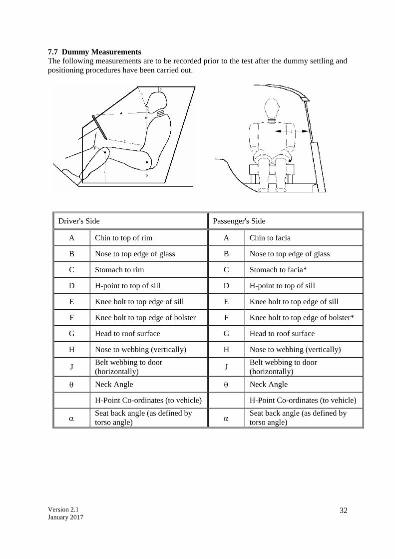
7.7 Dummy Measurements
The following measurements are to be recorded prior to the test after the dummy settling and
positioning procedures have been carried out.
H
Driver's Side Passenger's Side
A Chin to top of rim A Chin to facia
B Nose to top edge of glass B Nose to top edge of glass
C Stomach to rim C Stomach to facia*
D H-point to top of sill D H-point to top of sill
E Knee bolt to top edge of sill E Knee bolt to top edge of sill
F Knee bolt to top edge of bolster F Knee bolt to top edge of bolster*
G Head to roof surface G Head to roof surface
H Nose to webbing (vertically) H Nose to webbing (vertically)
J Belt webbing to door
(horizontally) J
Belt webbing to door
(horizontally)
Neck Angle Neck Angle
H-Point Co-ordinates (to vehicle) H-Point Co-ordinates (to vehicle)
Seat back angle (as defined by
torso angle)
Seat back angle (as defined by
torso angle)
J

Version 2.1
January 2017 33
8 STILL PHOTOGRAPHY
The following photographs will be taken pre and post-test unless otherwise indicated. Pre-test
photographs will be taken with the dummies in their final positions. Examples of the
photographs required are given in Annex 1 (Euro NCAP Frontal Impact Photograph
Specification Version 1).
No. View 1 Front view of barrier.
2 Side view of barrier.
3 Side view of barrier at 45 degrees to front.
4 Side view of barrier with vehicle.
5 Car RHS, with camera centred on junction of B-post waist, showing full car.
6 Car RHS, with camera centred on B-post waist, showing rear passenger compartment.
7 Car RHS, with camera aimed at waist height, showing driver's compartment.
8 Car RHS at 45 degrees to front.
9 Front view of car.
10 Car LHS at 45 degrees to front.
11 Car LHS, with camera aimed at waist height, showing front passenger's compartment.
12 Car LHS, with camera centred on B-post waist, showing rear passenger compartment.
13 Car LHS, with camera centred on B-post waist, showing full car.
14 Driver and seat to show driver compartment and position of seat relative to the sill.
15 To show area immediately in front of driver.
16 To show driver's footwell area and location of dummy's feet and pedals.
17 Passenger and seat to show compartment and position of seat relative to sill.
18 To show area immediately in front of passenger.
19 To show passenger footwell area and dummy's feet.
20 To show both child dummies and restraints through LHS rear door.
21 To show both child dummies and restraints through RHS rear door.
22 *Overall view of where the car has come to rest after impact (including barrier).
23 *To show position of all door latches and/or open doors.
24 *To show driver knee contacts with facia (airbag should be lifted if obscuring view).
25 *To show passenger knee contacts with facia (airbag should be lifted if obscuring
view).
26 ^RHS rear seat belt anchorage with child restraint and P3 dummy in place.
27 ^LHS rear seat belt anchorage with child restraint and P1 ½ dummy in place.
28 *Q3 dummy and restraint through RHS rear door.
29 *Q1 ½ dummy and restraint through LHS rear door.
* Post-test only, ^ Pre-test only
Version 2.1
January 2017 34
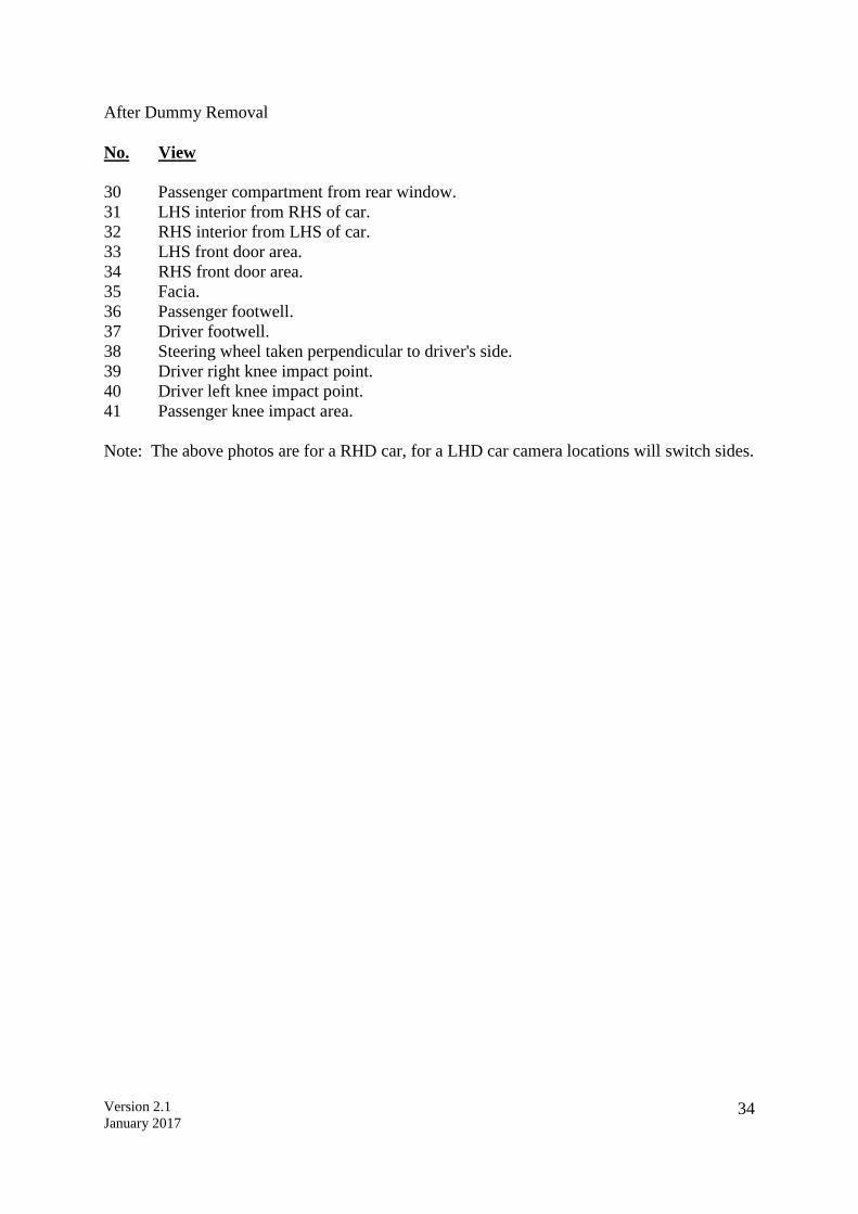
After Dummy Removal
No. View
30 Passenger compartment from rear window.
31 LHS interior from RHS of car.
32 RHS interior from LHS of car.
33 LHS front door area.
34 RHS front door area.
35 Facia.
36 Passenger footwell.
37 Driver footwell.
38 Steering wheel taken perpendicular to driver's side.
39 Driver right knee impact point.
40 Driver left knee impact point.
41 Passenger knee impact area.
Note: The above photos are for a RHD car, for a LHD car camera locations will switch sides.
Version 2.1
January 2017 35
9 TEST PARAMETERS
An on-board data acquisition unit will be used. This equipment will be triggered by a contact
plate at the point of first contact (t=0) and will record digital information at a sample rate of
20kHz (alternatively a sample rate of 10kHz may be used). The equipment conforms to SAE
J211.
BEFORE THE TEST, ENSURE THAT THE LIVE BATTERY IS CONNECTED, A SINGLE
KEY IS IN THE IGNITION, THE IGNITION IS ON AND THAT THE AIRBAG LIGHT ON
THE DASHBOARD ILLUMINATES AS NORMAL (WHERE FITTED)
If the vehicle is fitted with a brake pedal retraction mechanism which requires a vacuum present
in the brake system, the engine may be ran for a predetermined time, specified by the
manufacturer.
9.1 Deformable Barrier
Fix a deformable barrier to the concrete block. The height of this barrier should be 200mm
±5mm from the ground. A full description of the barrier and how it is to be fitted is given in
Appendix 1.
9.2 Speed
9.2.1 Measure the speed of the vehicle as near as possible to the point of impact.
9.2.2 This speed should be 64km/h (40mph) ± 1km/h. Record the actual test speed in the
test details.
TARGET SPEED = 64km/h ± 1km/h
9.3 Overlap
9.3.1 With the vehicle offered up against the barrier, tape a small pin as near as possible to
that edge of the deformable barrier which is to be struck.
9.3.2 Mark the point on the bumper of the vehicle where the pin should strike if an exact
overlap of 40% was achieved.
9.3.3 After the test, if the mark made by the pin is not within the tolerance rectangle described
below, film analysis will be used to try to assess the overlap. Both the horizontal and
vertical alignments shall be noted in the test report.
TARGET OVERLAP = 40% ± 20mm
TARGET VERTICAL ALIGNMENT = ± 25mm

Version 2.1
January 2017 36
After Test
9.4 Door Opening Force
The opening of vehicle doors post test shall be recorded on video.
9.4.1 Check that none of the doors have locked during the test
9.4.2 Try to open each of the doors (front doors followed by rear doors) using a spring-pull
attached to the external handle. The opening force should be applied perpendicular to
the door, in a horizontal plane, unless this is not possible. The manufacturer may
specify a reasonable variation in the angle of the applied force. Gradually increase the
force on the spring-pull, up to a maximum of 500N, until the door unlatches. If the door
does not open record this then try to unlatch the door using the internal handle. Again
attempt to open the door using the spring-pull attached to the external handle. Record
the forces required to unlatch the door and to open it to 45 in the test details.
9.4.3 If a door does not open with a force of 500N then try the adjacent door on the same
side of the vehicle. If this door then opens normally, retry the first door.
9.4.4 If the door still does not open, record in the test details whether the door could be
opened using extreme hand force or if tools were needed.
Note: In the event that sliding doors are fitted, the force required to open the door
sufficiently enough for an adult to escape should be recorded in place of the 45o opening
force.
9.5 Video of Dummy Position
9.5.1 The post impact positions of the dummies will be recorded on video.
9.6 Dummy Removal
9.6.1 Do not move the driver or passenger seats. Try to remove the dummies.
9.6.2 If the dummies cannot be removed with the seats in their original positions, recline the
seat back and try again. Note any entrapment of the dummy.
9.6.3 If the dummies can still not be removed, try to slide the seats back on their runners.
9.6.4 If the dummies can still not be moved, the seats can be cut out of the car.
9.6.5 Record the method used to remove the dummies.
9.7 Intrusion Measurements
Take the vehicle intrusion measurements. See Section 2.2 for a full description of how to do
this.
Where a specified requirement has not been met, ASEAN NCAP reserves the right to
decide whether or not the test will be considered as valid.
Version 2.1
January 2017 37
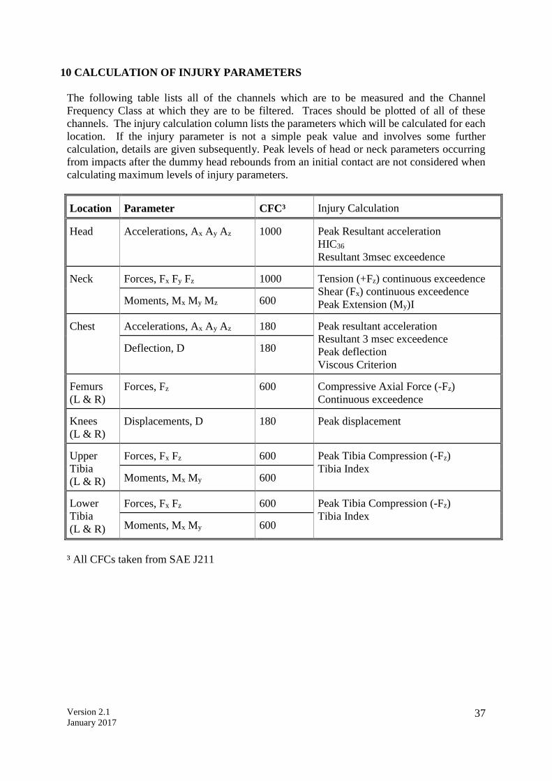
10 CALCULATION OF INJURY PARAMETERS
The following table lists all of the channels which are to be measured and the Channel
Frequency Class at which they are to be filtered. Traces should be plotted of all of these
channels. The injury calculation column lists the parameters which will be calculated for each
location. If the injury parameter is not a simple peak value and involves some further
calculation, details are given subsequently. Peak levels of head or neck parameters occurring
from impacts after the dummy head rebounds from an initial contact are not considered when
calculating maximum levels of injury parameters.
Location
Parameter
CFC³
Injury Calculation
Head
Accelerations, Ax Ay Az
1000
Peak Resultant acceleration
HIC36
Resultant 3msec exceedence Neck
Forces, Fx Fy Fz
1000
Tension (+Fz) continuous exceedence
Shear (Fx) continuous exceedence
Peak Extension (My)I
Moments, Mx My Mz
600
Chest
Accelerations, Ax Ay Az
180
Peak resultant acceleration
Resultant 3 msec exceedence
Peak deflection
Viscous Criterion
Deflection, D
180
Femurs
(L & R)
Forces, Fz
600
Compressive Axial Force (-Fz)
Continuous exceedence Knees
(L & R)
Displacements, D
180
Peak displacement
Upper
Tibia
(L & R)
Forces, Fx Fz
600
Peak Tibia Compression (-Fz)
Tibia Index Moments, Mx My
600
Lower
Tibia
(L & R)
Forces, Fx Fz
600
Peak Tibia Compression (-Fz)
Tibia Index Moments, Mx My
600
³ All CFCs taken from SAE J211
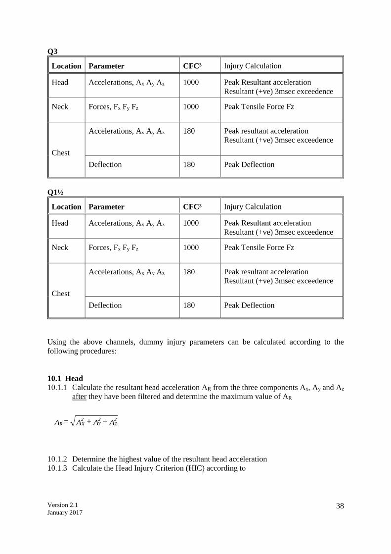
Version 2.1
January 2017 38
Q3 Location
Parameter
CFC³
Injury Calculation
Head
Accelerations, Ax Ay Az
1000
Peak Resultant acceleration
Resultant (+ve) 3msec exceedence Neck
Forces, Fx Fy Fz
1000
Peak Tensile Force Fz
Chest
Accelerations, Ax Ay Az
180
Peak resultant acceleration
Resultant (+ve) 3msec exceedence
Deflection
180
Peak Deflection
Q1½ Location
Parameter
CFC³
Injury Calculation
Head
Accelerations, Ax Ay Az
1000
Peak Resultant acceleration
Resultant (+ve) 3msec exceedence Neck
Forces, Fx Fy Fz
1000
Peak Tensile Force Fz
Chest
Accelerations, Ax Ay Az
180
Peak resultant acceleration
Resultant (+ve) 3msec exceedence
Deflection
180
Peak Deflection
Using the above channels, dummy injury parameters can be calculated according to the
following procedures:
10.1 Head
10.1.1 Calculate the resultant head acceleration AR from the three components Ax, Ay and Az
after they have been filtered and determine the maximum value of AR
10.1.2 Determine the highest value of the resultant head acceleration
10.1.3 Calculate the Head Injury Criterion (HIC) according to
A + A + A = A2Z
2Y
2XR

Version 2.1
January 2017 39
where AR is expressed in multiples of g. Maximise HIC for any time ‘window’ (t2 - t1)
up to 36 milliseconds.
10.1.4 Determine the acceleration level which AR exceeds for a cumulative time period of
three milliseconds i.e. the head 3msec exceedence.
10.2 Neck
10.2.1 Calculate the neck extension bending moment from fx.d - M = )iM( yy
Where My and Fx are bending moment and shear force respectively measured at the
transducer and d is the distance from the transducer to the interface
(d=0.01778).
See (SAEJ1733).
10.2.2 Determine the ‘continuous exceedence’ of both the neck tension (Fz positive) and neck
shear (Fx) forces.
10.3 Chest
10.3.1 Determine the greatest value of the chest deflection Dchest
10.3.2 Calculate the Viscous Criterion according to the equation
Viscous Criterion = 1.3 V(t)C(t)
D(t) is the instantaneous chest deflection at any time t. C(t) is the compression, related
to the chest deflection D(t)
0.229
D = C
(t)
(t)
V is the velocity of deflection and is calculated as the differential of the deflection with respect
to time:
t12
]D-D[ -] D-D[*8 = V
2)-(t2)+(t1)-(t1)+(t
(t)
where t is the time interval between successive digital samples of D(t). Calculate V(t)*C(t)
continuously with time and determine its greatest value.
10.4 Femurs
10.4.1 For each of the femurs, calculate the continuous exceedence in compression (Fz
negative)
)t-t(
.dtA
)t - t( = HIC12
R
t
t
2.5
12
2
1
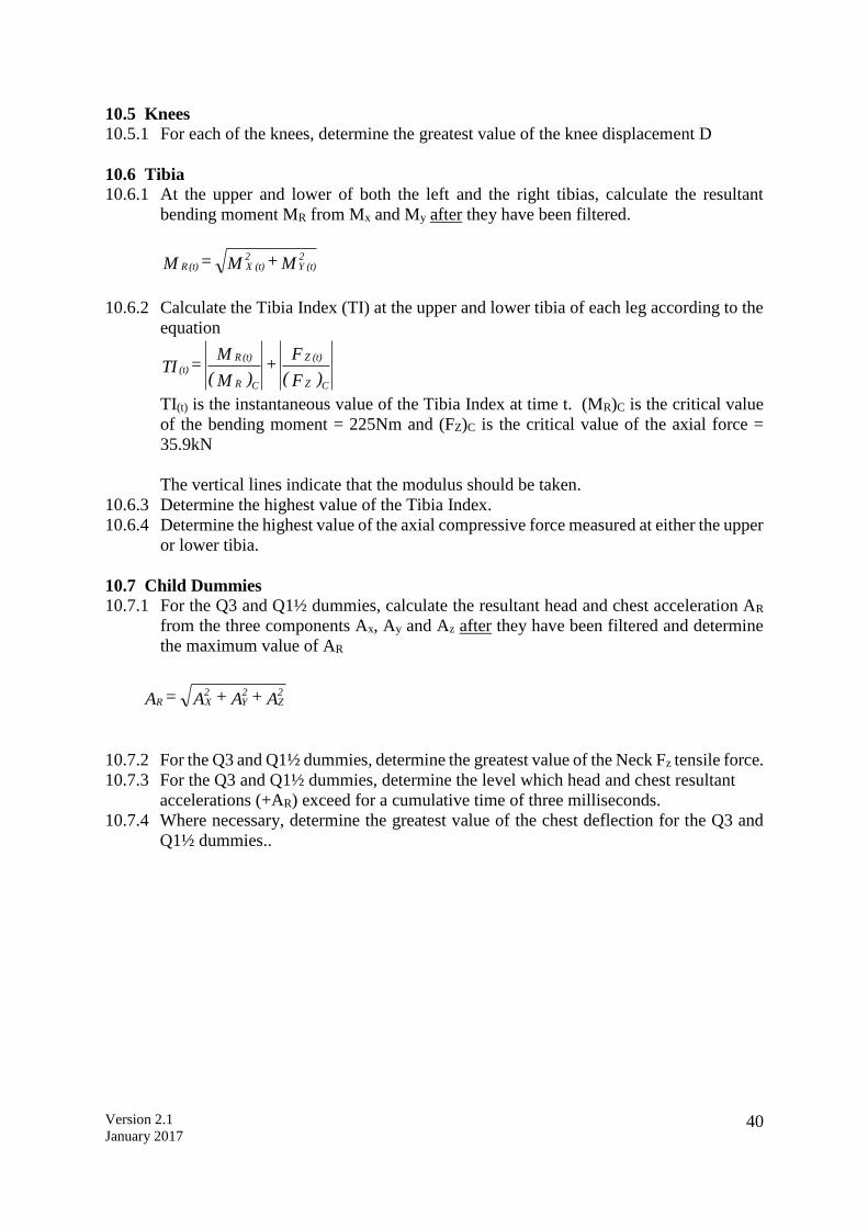
Version 2.1
January 2017 40
10.5 Knees
10.5.1 For each of the knees, determine the greatest value of the knee displacement D
10.6 Tibia
10.6.1 At the upper and lower of both the left and the right tibias, calculate the resultant
bending moment MR from Mx and My after they have been filtered.
M + M = M2
(t) Y2
(t) X(t) R
10.6.2 Calculate the Tibia Index (TI) at the upper and lower tibia of each leg according to the
equation
)F(
F +
)M(
M = TI
CZ
(t) Z
CR
(t) R
(t)
TI(t) is the instantaneous value of the Tibia Index at time t. (MR)C is the critical value
of the bending moment = 225Nm and (FZ)C is the critical value of the axial force =
35.9kN
The vertical lines indicate that the modulus should be taken.
10.6.3 Determine the highest value of the Tibia Index.
10.6.4 Determine the highest value of the axial compressive force measured at either the upper
or lower tibia.
10.7 Child Dummies
10.7.1 For the Q3 and Q1½ dummies, calculate the resultant head and chest acceleration AR
from the three components Ax, Ay and Az after they have been filtered and determine
the maximum value of AR
10.7.2 For the Q3 and Q1½ dummies, determine the greatest value of the Neck Fz tensile force.
10.7.3 For the Q3 and Q1½ dummies, determine the level which head and chest resultant
accelerations (+AR) exceed for a cumulative time of three milliseconds.
10.7.4 Where necessary, determine the greatest value of the chest deflection for the Q3 and
Q1½ dummies..
A + A + A = A2Z
2Y
2XR

Version 2.1
January 2017 41
Appendix I
Frontal Impact
Barrier Specification

Version 2.1
January 2017 42
BARRIER SPECIFICATION
The frontal impact barrier for testing and its mounting to the block shall conform to the
following specification:
1 Component and Material Specifications
The dimensions of the barrier are illustrated in Figure 1. The dimensions of the individual
components of the barrier are listed separately below.
Main Honeycomb Block
Dimensions
Height: 650mm [in direction of honeycomb ribbon (foil) axis]
Width: 1000mm
Depth: 450mm [in direction of honeycomb cell axes]
All above dimensions ± 2.5mm
Material: Aluminium 3003 (BS 1470)
Foil Thickness: 0.076mm ± 15%
Cell Size: 19.1mm ± 20%
Density: 28.6kg/m3 ± 20%
Crush Strength: 0.342MPa +0% -10%
[in accordance with test method described in Section 2]
Bumper Element
Dimensions
Height: 330mm [in direction of honeycomb ribbon axis]
Width: 1000mm
Depth: 90mm [in direction of honeycomb cell axes]
All above dimensions ± 2.5mm
Material: Aluminium 3003 (BS 1470)
Foil Thickness: 0.076mm ± 15%
Cell Size: 6.4mm ± 20%
Density: 82.6kg/m3 ± 20%
Crush Strength: 1.711MPa +0% -10%
[in accordance with test method described in Section 2]
Backing Sheet
Dimensions
Height: 800mm
Width: 1000mm
All above dimensions ± 2.5mm
Thickness: 2.0 ± 0.1mm
Material: Aluminium 5251/5052 (BS 1470)

Version 2.1
January 2017 43
Cladding Sheet
Dimensions
Height: 1700mm
Width: 1000mm
All above dimensions ± 2.5mm
Thickness: 0.81 ± 0.07mm
Material: Aluminium 5251/5052 (BS 1470)
Bumper Facing Sheet
Dimensions
Height: 330mm
Width: 1000mm
All above dimensions ± 2.5mm
Thickness: 0.81 ± 0.07mm
Material: Aluminium 5251/5052 (BS 1470)
Adhesive
The adhesive to be used throughout shall be a two-part polyurethane (such as Ciba-Geigy
XB5090/1 resin with XB5304 hardener, or equivalent).
2 Aluminium Honeycomb Certification
A complete testing procedure for certification of aluminium honeycomb is given in NHTSA
TP-214D-02. The following is a summary of the procedure as it should be applied to 0.342MPa
and 1.711MPa material for the frontal impact barrier.
2.1 Sample Locations To ensure uniformity of crush strength across the whole of the barrier face, 8 samples shall be
taken from 4 locations evenly spaced across the honeycomb block. For a block to pass
certification, 7 of these 8 samples must meet the crush strength requirements of the following
sections.
The location of the samples depends on the size of the honeycomb block. First, four samples,
each measuring 300mm300mm50mm thick shall be cut from the block of barrier face
material. Please refer to Figure 2 for an illustration of how to locate these sections within the
honeycomb block. Each of these larger samples shall be cut into samples for certification
testing (150mm150mm50mm). Certification shall be based on the testing of two samples
from each of these four locations. The other two should be made available to the customer,
upon request.
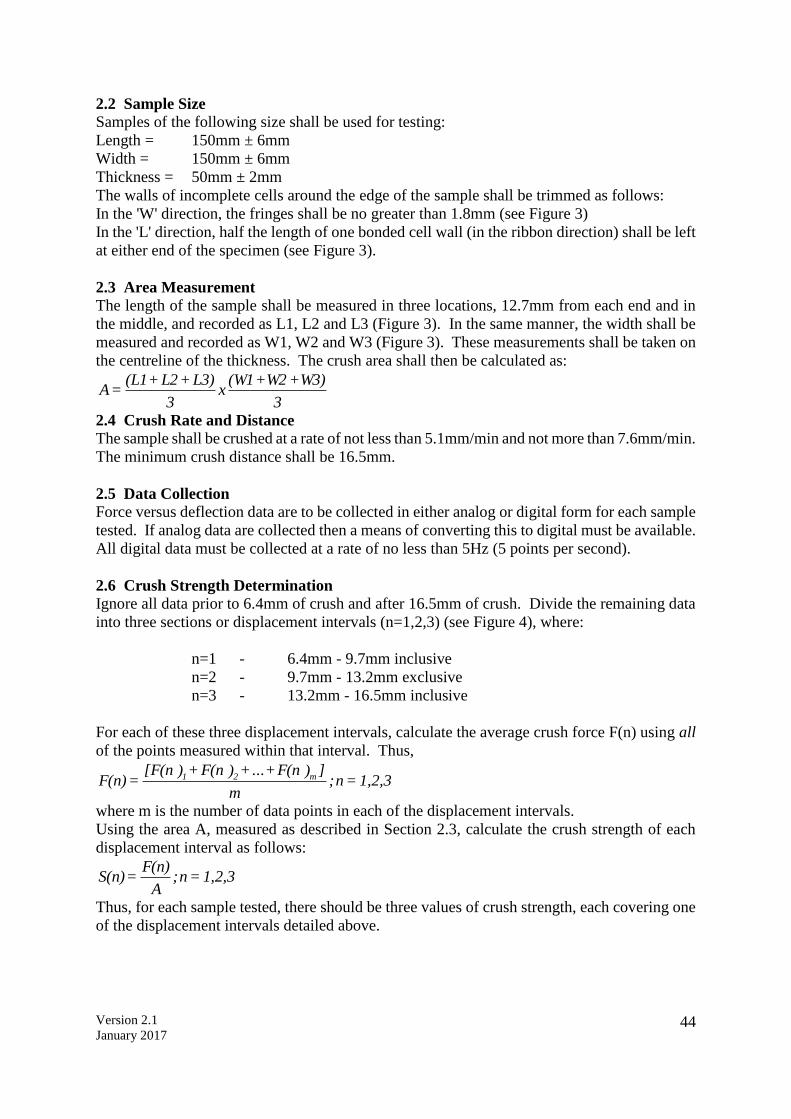
Version 2.1
January 2017 44
2.2 Sample Size Samples of the following size shall be used for testing:
Length = 150mm ± 6mm
Width = 150mm ± 6mm
Thickness = 50mm ± 2mm
The walls of incomplete cells around the edge of the sample shall be trimmed as follows:
In the 'W' direction, the fringes shall be no greater than 1.8mm (see Figure 3)
In the 'L' direction, half the length of one bonded cell wall (in the ribbon direction) shall be left
at either end of the specimen (see Figure 3).
2.3 Area Measurement The length of the sample shall be measured in three locations, 12.7mm from each end and in
the middle, and recorded as L1, L2 and L3 (Figure 3). In the same manner, the width shall be
measured and recorded as W1, W2 and W3 (Figure 3). These measurements shall be taken on
the centreline of the thickness. The crush area shall then be calculated as:
3
W3)+W2+(W1x
3
L3)+L2+(L1=A
2.4 Crush Rate and Distance The sample shall be crushed at a rate of not less than 5.1mm/min and not more than 7.6mm/min.
The minimum crush distance shall be 16.5mm.
2.5 Data Collection Force versus deflection data are to be collected in either analog or digital form for each sample
tested. If analog data are collected then a means of converting this to digital must be available.
All digital data must be collected at a rate of no less than 5Hz (5 points per second).
2.6 Crush Strength Determination Ignore all data prior to 6.4mm of crush and after 16.5mm of crush. Divide the remaining data
into three sections or displacement intervals (n=1,2,3) (see Figure 4), where:
n=1 - 6.4mm - 9.7mm inclusive
n=2 - 9.7mm - 13.2mm exclusive
n=3 - 13.2mm - 16.5mm inclusive
For each of these three displacement intervals, calculate the average crush force F(n) using all
of the points measured within that interval. Thus,
1,2,3=n;m
])F(n...++)F(n+)[F(n=F(n) m21
where m is the number of data points in each of the displacement intervals.
Using the area A, measured as described in Section 2.3, calculate the crush strength of each
displacement interval as follows:
1,2,3=n;A
F(n)=S(n)
Thus, for each sample tested, there should be three values of crush strength, each covering one
of the displacement intervals detailed above.

Version 2.1
January 2017 45
2.7 Sample Crush Strength Specification For a honeycomb sample to pass this certification, the average crush strength of each of the
three displacement intervals must meet the following condition:
0.308MPa S(n) 0.342MPa for 0.342MPa material
1.540MPa S(n) 1.711MPa for 1.711MPa material
n=1,2,3
Note: It is not satisfactory to calculate the crush strength averaged over the entire crush
distance (6.4mm - 16.5mm). A sample may give an overall average that satisfies the
requirement, while individual displacement intervals may not. The procedure of Section 2.6
must therefore be followed.
2.8 Block Crush Strength Specification Eight samples are to be tested from four locations, evenly spaced across the block. For a block
to pass certification, 7 of the 8 samples must meet the crush strength specification of the
previous section.
3 Adhesive Bonding Procedure Immediately before bonding, Aluminium sheet surfaces to be bonded shall be thoroughly
cleaned using a suitable solvent, such as 1,1,1 Trichloroethane. This is to be carried out at least
twice or as required to eliminate grease or dirt deposits. The cleaned surfaces shall then be
abraded using 120 grit abrasive paper. Metallic/Silicon Carbide abrasive paper is not to be
used. The surfaces must be thoroughly abraded and the abrasive paper changed regularly
during the process to avoid clogging, which may lead to a polishing effect. Following abrading,
the surfaces shall be thoroughly cleaned again, as above. In total, the surfaces shall be solvent
cleaned at least four times. All dust and deposits left as a result of the abrading process must
be removed, as these will adversely affect bonding.
The adhesive shall be applied to one surface only, using a ribbed rubber roller. In cases where
honeycomb is to be bonded to Aluminium sheet, the adhesive should be applied to the
Aluminium sheet only. A maximum of 0.5kg/m2 shall be applied evenly over the surface,
giving a maximum film thickness of 0.5mm.

Version 2.1
January 2017 46
4 Construction
The main honeycomb block shall be adhesively bonded to the backing sheet such that the cell
axes are perpendicular to the sheet. The cladding sheet shall be bonded to the front surface of
the honeycomb block. The top and bottom surfaces of the cladding sheet shall NOT be bonded
to the main honeycomb block but should be positioned closely to it. The cladding sheet shall
be adhesively bonded to the backing sheet at the mounting flanges.
The bumper element shall be adhesively bonded to the front of the cladding sheet such that the
cell axes are perpendicular to the sheet. The bottom of the bumper element shall be flush with
the bottom surface of the cladding sheet. The bumper facing sheet shall be adhesively bonded
to the front of the bumper element.
The bumper element shall then be divided into three equal sections by means of two horizontal
slots. These slots shall be cut through the entire depth of the bumper section and extend the
whole width of the bumper. The slots shall be cut using a saw; their width shall be the width
of the blade used and shall not exceed 4.0mm.
Clearance holes for mounting the barrier are to be drilled in the mounting flanges (shown in
Figure 5). The holes shall be of 9.5mm diameter. Five holes shall be drilled in the top flange
at a distance of 40mm from the top edge of the flange and five in the bottom flange, 40mm
from the bottom edge of that flange. The holes shall be at 100mm, 300mm, 500mm, 700mm,
900mm from either edge of the barrier. All holes shall be drilled to ±1mm of the nominal
distances. These hole locations are a recommendation only. Alternative positions may be used
which offer at least the mounting strength and security as that provided by the above mounting
specifications.
5 Mounting
The deformable barrier shall be rigidly fixed to the edge of a block of reinforced concrete
weighing at least 70 tonnes or to some structure attached thereto. The attachment of the barrier
face shall be such that the vehicle shall not come into contact with any structure at any height
above 75mm from the top surface of the barrier (excluding the upper flange) during any stage
of the impact. The front face of the surface to which the deformable face is attached shall be
flat and continuous over the height and width of the face and shall be vertical and perpendicular
to the axis of the run-up track. The attachment surface shall not be displaced by more than
10mm during any stage of the test. If necessary, additional anchorage or arresting devices shall
be used to prevent displacement of the concrete block. The edge of the deformable barrier shall
be aligned with the edge of the attachment surface appropriate for the side of the vehicle to be
tested.
The deformable barrier shall be attached by means of ten bolts, five in the top mounting flange
and five in the bottom. These bolts shall be of at least 8mm diameter. Steel clamping strips
shall be used for both the top and bottom mounting flanges (see Figure 5). These strips shall
be 60mm high and 1000mm wide and have a thickness of at least 3mm. The edges of the
clamping strips should be rounded off to prevent tearing of the barrier against the strip during
impact. The edge of the strip should be located no more than 5mm above the base of the upper
barrier mounting flange, or 5mm below the top of the lower barrier mounting flange. Five
clearance holes of 9.5mm diameter shall be drilled in both strips to correspond with those in
the mounting flange on the barrier (see Section 4). The mounting strip and barrier flange holes

Version 2.1
January 2017 47
may be widened from 9.5mm up to a maximum of 25mm in order to accommodate differences
in back-plate arrangements and/or load cell wall hole configurations. None of the fixtures shall
fail in the impact test.
In the case where the deformable barrier is mounted on a load cell wall (LCW) it should be
noted that the above dimensional requirements for mountings are intended as a minimum.
Where a LCW is present, the mounting strips may be extended to accommodate higher
mounting holes for the bolts. If the strips are required to be extended, then thicker gauge steel
should be used accordingly, such that the barrier does not pull away from the wall, bend or tear
during the impact. If an alternative method of mounting the barrier is used, it should be at least
as secure as that specified in the above paragraphs.

Version 2.1
January 2017 48
Figure 2 Locations of Samples for Certification

Version 2.1
January 2017 49
Figure 3 Honeycomb Axes and Measured Dimensions
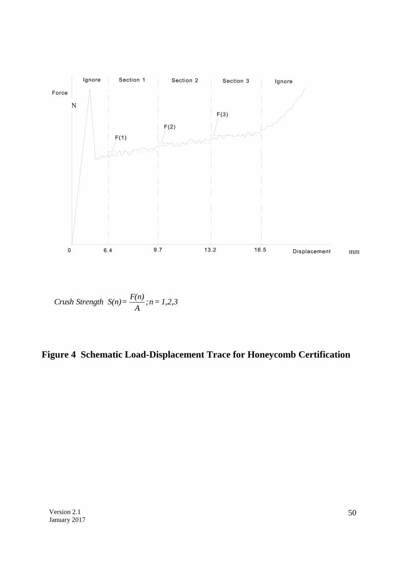
Version 2.1
January 2017 50
Figure 4 Schematic Load-Displacement Trace for Honeycomb Certification
1,2,3=n;A
F(n)= S(n) StrengthCrush
N
mm
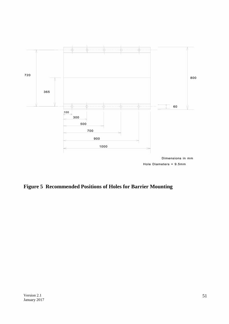
Version 2.1
January 2017 51
Figure 5 Recommended Positions of Holes for Barrier Mounting

Version 2.1
January 2017 52
Members of ASEAN NCAP Technical Committee Yahaya Ahmad Malaysian Institute of Road Safety Research (MIROS) Khairil Anwar Abu Kassim Malaysian Institute of Road Safety Research (MIROS) Mohd Hafzi Md Isa Malaysian Institute of Road Safety Research (MIROS) Ahmed Ismail Automobile Association of Malaysia (AAM) Assoc. Prof. Dr. Saiprasit Koetniyom The Sirindhorn International Thai German Graduate School of Engineering (TGGS) Assoc. Prof. Dr. Julaluk Carmai The Sirindhorn International Thai German Graduate School of Engineering (TGGS) Dr. Ir. Sigit P. Santosa Institut Teknologi Bandung (ITB) Dr. Ly Hung Anh Ho Chi Minh City University of Technology (HCMUT) Dr. Atsuhiro Konosu Japan Automobile Research Institute (JARI) Salina Mustaffa Malaysian Institute of Road Safety Research (MIROS)

Version 2.1
January 2017 53
ASEAN NCAP Ground Floor, Lot 127, Jalan TKS 1, Taman Kajang Sentral, 43000 Kajang, Selangor, Malaysia.
+603-8924 9200 (ext. 425)
+603-8733 2005
www.aseancap.org