Embed Size (px)
Citation preview
DOEINASAI50112-75 NASA TM-I 00899
Testing of a Variable-Stroke Stirling Engine
Lanny G. Thieme National Aeronautics and Space Administration Lewis Research Center
and
David J. Allen Sverdrup Technology, Inc. NASA Lewis Research Center Group
Work performed for U.S. DEPARTMENT OF ENERGY Conservation and Renewable Energy Office of Vehicle and Engine R&D
(EASE-TM-100855) IESZING CE A N8 8-3 C4 72 VLBIAbLE-SIRCBE I l J 6 L I b G EPGI I E F i n d Eeport 4 h A S A ) 2 1 F CSCL 1 C B
Uncld is L) G3/85 0 365643
\
Prepared for the 21 st Intersociety Energy Conversion Engineering Conference (IECEC) cosponsored by the ACS, SAE, ANS, ASME, IEEE, AIAA, and AlChE San Diego, California, August 25-29. 1986
https://ntrs.nasa.gov/search.jsp?R=19880021088 2018-06-06T01:52:31+00:00Z

DISCLAIMER
This report was prepared as an account of work sponsored by an agency of the United States Government. Neither the United States Government nor any agency thereof, nor any of their employees, makes any warranty, express or implied, or assumes any legal liability or responsibility for the accuracy, completeness, or usefulness of any information, apparatus, product, or process disclosed, or represents that its use would not infringe privately owned rights. Reference herein to any specific commercial product, process, or service by trade name, trademark, manufacturer, or otherwise, does not necessarily constitute or imply its endorsement, recommendation, or favoring by the United States Government or any agency thereof. The views and opinions of authors expressed herein do not necessarily state or reflect those of the United States Government or any agency thereof.
Printed in the United States of America
Available from National Technical Information Service U.S. Department of Commerce 5285 Port Royal Road Springfield, VA 22161
Printed copy: A02 Microfiche copy: A01
NTlS price codes1
%odes are used for pricing all publications. The code is determined by the number of pages in the publication. Information pertaining to the pricing codes can be found in the current issues of the following publications, which are generally available in most libraries: Energy Research Abstracts (ERA), Government Reports Announcements and Index (GRA and I); Scientific and Technical Abstract Reports (STAR). and publication, NTIS-PR-360 available from NTlS at the above address.
,
L
DOE/NASA/50112-75 NASA TM-I 00899
Testing of a Variable-Stroke Stirling Engine
Lanny G. Thieme National Aeronautics and Space Administration Lewis Research Center Cleveland, Ohio 441 35
and
David J. Allen Sverdrup Technology, Inc. NASA Lewis Research Center Group Cleveland, Ohio 441 35
Work performed for U.S. DEPARTMENT OF ENERGY Conservation and Renewable Energy Office of Vehicle and Engine R&D Washington, D.C. 20545 Under Interagency Agreement DE-AI01 -85CE50112
Prepared for the 21 st Intersociety Energy Conversion Engineering Conference (I ECEC) cosponsored by the ACS, SAE, ANS, ASME, IEEE, AIAA, and AlChE San Diego, California, August 25-29, 1986

T E S T I N G OF A VARIABLE-STROKE STIRLING ENGINE
Lanny G. Thieme Na t iona l Aeronaut ics and Space A d m i n i s t r a t i o n
Lewis Research Center Cleveland, Oh io 44135
and
David J . A l l e n Sverdrup Technology, I n c .
NASA Lewis Research Center Group Cleveland, Oh io 44135
SUMMARY
I n suppor t o f the U.S. Department o f Energy 's S t i r l i n g Engine Highway V e h i c l e Systems Program, NASA Lewis i n v e s t i g a t e d the use o f v a r i a b l e s t r o k e as an a l t e r n a t i v e t o the complex mean-pressure c o n t r o l system for c o n t r o l l i n g t h e power o u t p u t o f an automot ive S t i r l i n g engine.
e f f i c i e n c y ga in , and l e s s s t a t i c w o r k i n g - f l u i d leakage from the engine due to a lower number o f connect ions t o the work ing space. For t h i s i n v e s t i g a t i o n , t h e Advenco S t i r l i n g engine was purchased from P h i l i p s Research L a b o r a t o r i e s o f t h e Nether lands .
ID
m 0
w
The p r i m a r y b e n e f i t s o f f e r e d I
l-7 by v a r i a b l e - s t r o k e o p e r a t i o n are a s imp ler c o n t r o l system, a p o s s i b l e p a r t - l o a d
Tes t i ng o f the Advenco a t NASA Lewis has been completed.
The Advenco i s a f o u r - c y l i n d e r , doub le-ac t ing engine des igned for a maxi-
The s t r o k e can be v a r i e d from
mum engine o u t p u t of about 40 kW w i t h hydrogen work ing f l u i d a t a d e s i g n mean compression-space pressure o f 10 MPa. w i t h a v a r i a b l e - a n g l e swash-plate d r i v e system. 10 mm a t a 5" swash-plate ang le t o 48.5 mm a t a 22" swash-plate angle.
The engine was t e s t e d for a t o t a l o f about 70 h r w i t h b o t h h e l i u m and hydrogen work ing f l u i d s and over a range of pressures, strokes, and engine speeds. The maximum brake power and brake gross thermal e f f i c i e n c y o b t a i n e d were 10.0 kW and 22.1 percent , r e s p e c t i v e l y . These va lues were recorded for a r u n a t 5-MPa mean compression-space pressure w i t h hydrogen work ing f l u i d and a 40-mm s t r o k e .
V a r i a b l e - s t r o k e o p e r a t i o n i s ach ieved
Comparisons w i t h computer s i m u l a t i o n p r e d i c t i o n s i n d i c a t e d t h a t t h e meas- u red performance was lower than expected. due t o excess ive mechanical losses , as i n d i c a t e d by excess ive heat r e j e c t e d to the o i l and by the occurrence o f two dr ive-sys tem f a i l u r e s .
I t i s f e l t t h a t t h i s was p r i m a r i l y
T e s t s w e r e performed t o a l l o w comparisons o f p a r t - l o a d e f f i c i e n c i e s o b t a i n e d w i t h v a r i a b l e - p r e s s u r e and w i t h v a r i a b l e - s t r o k e o p e r a t i o n . t e s t d a t a and the computer s i m u l a t i o n p r e d i c t i o n s showed a p a r t - l o a d e f f i - c i e n c y g a i n w i t h v a r i a b l e s t roke t h a t inc reased w i t h i n c r e a s i n g engine speed and was g r e a t e r w i t h h e l i u m work ing f l u i d than w i t h hydrogen. Th is e f f i c i e n c y g a i n was p r i m a r i l y due t o lower f l ow l o s s e s th rough the heat exchangers and t o reduced heat losses t h a t tended t o decrease w i t h reduced s t r o k e and pressure r a t i o (such as s h u t t l e l osses ) . For automot ive a p p l i c a t i o n s o p e r a t i n g w i t h
Both t h e

hydrogen work ing f l u i d and m a i n l y a t l ower engine speeds, l i t t l e or no g a i n i n p a r t - l o a d e f f i c i e n c y would be expected.
Two f a i l u r e s w i t h t h e v a r i a b l e - a n g l e swash-plate d r i v e system were encoun- t e r e d d u r i n g t h e t e s t program; these f a i l u r e s l i m i t e d t e s t i n g t o t h e lower power l e v e l s . i n t h e v a r i a b l e - s t r o k e concept b u t t h e y do emphasize t h e need f o r c a r e f u l des ign i n t h e area o f t h e crossheads where t h e f a i l u r e s occu r red .
The f a i l u r e s a r e n o t t hough t t o be caused by problems i n h e r e n t
Th is paper summarizes t h e e n t i r e Advenco t e s t program and p r e s e n t s d e t a i l e d hydrogen t e s t d a t a and i n f o r m a t i o n on t h e second d r i ve -sys tem f a i l - u r e . sented i n d e t a i l i n an e a r l i e r t e s t r e p o r t ( r e f . 1 ) .
The h e l i u m t e s t r e s u l t s and a d e s c r i p t i o n o f t h e f i r s t f a i l u r e were p re -
INTRODUCTION
T h i s t e s t i n g a t NASA Lewis was done i n suppor t o f t h e U.S. Department of Energy (DOE) S t i r l i n g Engine Highway V e h i c l e Systems Program. The NASA Lewis Research Center , through i n t e r a g e n c y agreement DE-AI01-85CE50112 w i t h DOE, i s r e s p o n s i b l e for management o f t h e p r o j e c t under t h e program d i r e c t i o n of t h e DOE O f f i c e o f T r a n s p o r t a t i o n Systems, Heat Engine P r o p u l s i o n D i v i s i o n .
The power o u t p u t o f most k i n e m a t f c S t i r l i n g engines i s v a r i e d by changing t h e mean pressure l e v e l o f t h e work ing f l u i d . f o r au tomot i ve a p p l i c a t i o n s , a r e l a t i v e l y complex mean-pressure c o n t r o l system i s r e q u i r e d w i t h a t t e n d a n t r e l i a b i l i t y and maintenance problems. t h i s c o n t r o l system, t h e many connect ions t o t h e work ing space add more poten- t i a l leakage paths f o r t h e work ing f l u i d . Whi le exper ience w i t h t h e mean- p ressu re c o n t r o l system demonstrates v e r y good performance, these p o s s i b l e problems have r a i s e d i n t e r e s t i n i n v e s t i g a t i n g a l t e r n a t i v e s f o r c o n t r o l l i n g t h e power o u t p u t o f a S t i r l i n g engine.
To o b t a i n t h e d e s i r e d response
A lso , w i t h
T h i s i n t e r e s t l e d t o the purchase o f the Advenco (Advanced Engine Concept) S t i r l i n g engine from P h i l i p s Research L a b o r a t o r i e s o f t h e Ne the r lands . engine i s a f o u r - c y l i n d e r , doub le -ac t i ng engine designed f o r a maximum engine o u t p u t of about 40 kW w i t h hydrogen work ing f l u i d . The major d i f f e r e n c e between t h i s and c u r r e n t k i n e m a t i c S t i r l i n g engines i s t h e use o f v a r i a b l e s t r o k e as a method of power c o n t r o l . angle swash-plate d r i v e s y s t e m .
T h i s
The s t r o k e i s v a r i e d w i t h a v a r i a b l e -
The engine was i n s t a l l e d i n a t e s t c e l l a t NASA Lewis. The o b j e c t i v e s of t h e Advenco t e s t i n g were as fol lows:
( 1 ) Evaluate t h e b e n e f i t s o f v a r i a b l e - s t r o k e power c o n t r o l r e l a t i v e t o mean-pressure c o n t r o l ; compare t h e p a r t - l o a d e f f i c i e n c i e s o b t a i n e d w i t h v a r i a b l e - s t r o k e and v a r i a b l e - p r e s s u r e o p e r a t i o n
( 2 ) Evaluate v a r i a b l e - a n g l e swash-plate d r i v e as a system fo r o b t a i n i n g v a r i a b l e stroke
( 3 ) Prov ide i n f o r m a t i o n t o S t i r l i n g engine R & D companies f o r develop- ment o f va r iab le -ang le swash-plate d r i v e
(4) O b t a i n t e s t da ta ove r a range o f s t r o k e s t o a i d i n t h e v a l i d a t i o n o f S t i r l i n g engine computer s i m u l a t i o n s
2

The b e n e f i t s o f v a r i a b l e - s t r o k e c o n t r o l w i t h r e s p e c t to mean-pressure con- t r o l i n c l u d e reduced c o m p l e x i t y o f the power c o n t r o l system and a p o s s i b l e p a r t - l o a d e f f i c i e n c y g a i n . The use o f t h e v a r i a b l e - s t r o k e c o n t r o l system e l i m - i n a t e s many p o t e n t i a l w o r k i n g - f l u i d leakage pa ths a s s o c i a t e d w i t h t h e mean- p ressu re c o n t r o l system. Also, if des i red , i t p e r m i t s t h e use o f a p r e s s u r i z e d crankcase t h a t may reduce t h e s h a f t - s e a l i n g problem.
T h i s paper p r e s e n t s a summary o f t h e Advenco t e s t program a t NASA Lewis. I t b r i e f l y d e s c r i b e s t h e Advenco engine and t e s t setup, p r e s e n t s t e s t r e s u l t s w i t h h e l i u m and hydrogen work ing f l u i d s , and d i scusses two eng ine f a i l u r e s t h a t l i m i t e d t e s t i n g t o low power l e v e l s . A d e t a i l e d d e s c r i p t i o n o f t h e engine and t h e t e s t r e s u l t s o b t a i n e d w i t h he l ium work ing f l u i d were i n c l u d e d i n an e a r l i e r t e s t r e p o r t ( r e f . 1 ) .
ENGINE D E S C R I P T I O N
The Advenco engine i s a f o u r - c y l i n d e r , d o u b l e - a c t i n g S t i r l i n g engine designed f o r a maximum o u t p u t of about 40 kW w i t h hydrogen work ing f l u i d . The Advenco was b u i l t by P h i l i p s Research L a b o r a t o r i e s o f t h e Ne the r lands . A v a r i a b l e - a n g l e swash-plate d r i v e system i s used t o v a r y p i s t o n s t r o k e i n o r d e r t o c o n t r o l engine power o u t p u t . The s t r o k e can be v a r i e d from 10 mm a t a 5" swash-plate ang le t o 4 8 . 5 mm a t a 22" swash-plate ang le . sure l e v e l i s 10 MPa. The e f f i c i e n c y was maximized a t a par t -power c o n d i t i o n co r respond ing t o a 14" swash-plate angle and a 4500-rpm engine speed.
The des ign mean pres-
F i g u r e 1 i s a photograph of the Advenco engine i n i t s t e s t f a c i l i t y a t NASA Lewis. The engine i s shown i n c ross s e c t i o n i n f i g u r e 2. The Advenco engine has been d e s c r i b e d i n d e t a i l i n an e a r l i e r NASA t e s t r e p o r t ( r e f . 1 ) and a l s o as o r i g i n a l l y manufactured by P h i l i p s Research L a b o r a t o r i e s ( r e f . 2 ) .
The v a r i a b l e - a n g l e swash-plate assembly i s shown i n f i g u r e 3. The swash p l a t e r o t a t e s w i t h t h e main s h a f t . m a i n t a i n l i n e c o n t a c t w i t h the s l i d e r s . A balance r i n g i s a t t a c h e d around t h e o u t s i d e o f t h e swash p l a t e .
I t s surface i s made s l i g h t l y convex t o
To change t h e ang le o f t h e swash p l a t e , h y d r a u l i c f l u i d i s p o r t e d th rough c o n c e n t r i c channels . in t h e main s h a f t to t h e vane-type r o t a r y a c t u a t o r mounted behind t h e swash p l a t e . The h y d r a u l i c p ressu re f o r c e s t h e a c t u a t o r t o r o t a t e r e l a t i v e t o t h e main s h a f t . T h i s r o t a t i o n i s t r a n s m i t t e d by gears to t h e swash p l a t e . The swash p l a t e ' s r o t a t i o n around a t i l t e d s e c t i o n o f t h e main s h a f t causes t h e swash-plate angle to change. F u r t h e r e x p l a n a t i o n o f t h e v a r i a b l e - ang le swash-plate d r i v e sys tem can be found i n r e f e r e n c e 3.
F i g u r e 4 shows a t y p i c a l crosshead and s l i d e r s t h a t se rve as t h e a t t a c h - ment between t h e r e c i p r o c a t i n g r o d and p i s t o n and t h e r o t a t i n g swash p l a t e . O i l l u b r i c a t i o n i s p r o v i d e d t o b o t h s i d e s o f t h e s l i d e r s . F i g u r e 4 a l s o shows t h e r o l l s o c k r o d seal c a r t r i d g e and r o l l s o c k r o d seal used i n t h e Advenco t o seal o f f t h e h igh-pressure work ing f l u i d i n t h e work ing space f r o m t h e o i l i n t h e crankcase.
3

TEST FACILITY
The NASA Lewis t e s t f a c i l i t y used i n t h e i n i t i a l Advenco t e s t i n g with h e l i u m work ing f l u i d i s desc r ibed i n d e t a i l i n r e f e r e n c e 1. These t e s t s used n a t u r a l gas as the f u e l . The a l r f l o w was v a r i e d t o c o n t r o l t h e h e a t e r tempera- t u r e t o t h e average of f o u r thermocouples t h a t measured hea te r - tube work ing f l u i d temperature. The n a t u r a l gas f u e l was c o n t r o l l e d by a mechanical con- t r o l l e r which va r ied t h e f u e l f low t o s e t t h e d e s i r e d a i r - t o - f u e l r a t i o . The coo l i ng -wa te r i n l e t temperature was c o n t r o l l e d t o a c o n s t a n t v a l u e .
A d i r e c t - c u r r e n t dynamometer w i t h a l o w - f r i c t i o n , o i l - f l o a t e d c r a d l e - b e a r i n g system absorbed t h e engine power o u t p u t ; t o rque was measured w i t h a l o a d c e l l . Engine s t r o k e was determined e l e c t r o n i c a l l y from a l i n e a r v a r i a b l e d i f f e r e n t i a l t ransformer (LVDT) s i g n a l . The LVDT measured p i s t o n p o s i t i o n and was a t t a c h e d t o t h e r e a r o f one o f t h e crossheads.
The i n i t i a l Advenco t e s t i n g w i t h h e l i u m work ing f l u i d ended w i t h a ma jo r dr ive-system f a i l u r e . F o l l o w i n g t h e r e b u i l d i n g o f t h e eng ine , t h e t e s t f a c i l - i t y was m o d i f i e d prior t o t e s t i n g w i t h hydrogen work ing f l u i d . These changes were made t o ensure t h e d e s i r e d a i r - t o - f u e l r a t i o and to i n c r e a s e t h e accuracy o f t h e engine energy balance. Because t h e mechanical a i r - f u e l c o n t r o l l e r was no l onger p r o v i d i n g a r e p e a t a b l e a i r - t o - f u e l r a t i o , i t was r e p l a c e d w i t h an e l e c t r o n i c c o n t r o l c i r c u i t . T h i s c i r c u i t measured t h e a i r f l o w and then a d j u s t e d a gas-f low v a l v e t o g i v e t h e c o r r e c t f u e l f low a c c o r d i n g to a p ro - grammed a i r - t o - f u e l r a t i o schedule, The f u e l system was m o d i f i e d t o use 98 pe rcen t pu re methane i n s t e a d o f n a t u r a l gas i n o r d e r t o g i v e an improved knowl- edge o f t h e heat i n p u t from t h e f u e l . va lue w i t h n a t u r a l gas was about '5 p e r c e n t .
The y e a r l y v a r i a t i o n o f t h e h e a t i n g
TEST RESULTS
A s t a t i c pressure decay t e s t was made b e f o r e each eng ine s t a r t to compare work ing f l u i d leakage w i t h p rev ious r u n s . A f t e r each engine s t a r t , s tandard warmup c o n d i t i o n s were s e t and the engine was r u n f o r 30 min. Performance a t these c o n d i t i o n s was checked a g a i n s t r e s u l t s from p r e v i o u s runs to v e r i f y p roper engine opera t i on .
For a l l t e s t s , t h e average hea te r - tube gas temperature was c o n t r o l l e d t o 625 " C and t h e cool ing-water i n l e t temperature t o 50 " C . To a l l o w comparison o f p a r t - l o a d e f f i c i e n c i e s o b t a i n e d w i t h v a r i a b l e - s t r o k e and v a r i a b l e - p r e s s u r e o p e r a t i o n , t h e Advenco was t e s t e d o v e r a range o f b o t h p ressu res and s t r o k e s . For each mean pressure l e v e l , a s e r i e s o f runs was made a t d i f f e r e n t engine strokes. For each engine s t r o k e and p ressu re , t h e engine speed was v a r i e d ove r t h e range of 1500 t o 3500 rpm i n 500-rpm increments. The procedure t h a t was f o l l o w e d was t o s t a r t a t t h e lower va lues o f mean-compression space p res - sure and engine stroke and then p r o g r e s s i v e l y i n c r e a s e these parameters.
The r e s u l t s o f t h e i n i t i a l engine t e s t s w i t h h e l i u m work ing f l u i d a r e presented i n re fe rence 1 . The maximum b rake power and b rake g ross thermal e f f i c i e n c y curves o b t a i n e d i n these t e s t s a r e shown i n f i g u r e 5. Brake g ross thermal e f f i c i e n c y was c a l c u l a t e d by d i v i d i n g t h e brake power by t h e h e a t i n p u t from t h e f u e l (based on t h e lower h e a t i n g va lue ) t i m e s 100. T h i s s e r i e s o f t e s t s was ended by a major d r i ve -sys tem f a i l u r e t h a t o c c u r r e d a t 5-MPa mean
4

I -
compression-space p ressu re , 40-mm stroke, and 3000-rpm eng ine speed f a i l u r e and t h e subsequent engine r e p a i r s a r e d e s c r i b e d i n t h e s e c t "Drive-System F a i l u r e s " .
F o l l o w i n g comp le t i on of the engine r e p a i r s , checkout r u n s were
T h i s on
made w i t h h e l i u m work ing f l u i d . t e s t i n g ; t h i s l e d t o m o d i f i c a t i o n s o f t h e t e s t f a c i l i t y t h a t i n c l u d e d t h e i n s t a l l a t i o n o f a new a i r - t o - f u e l r a t i o c o n t r o l system and t h e changeover t o methane f u e l .
Performance was v e r y d i f f i c u l t t o r e p e a t d u r i n g t h i s
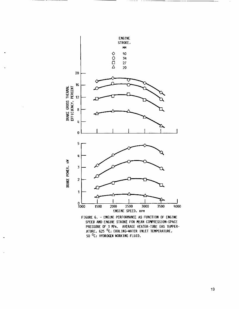
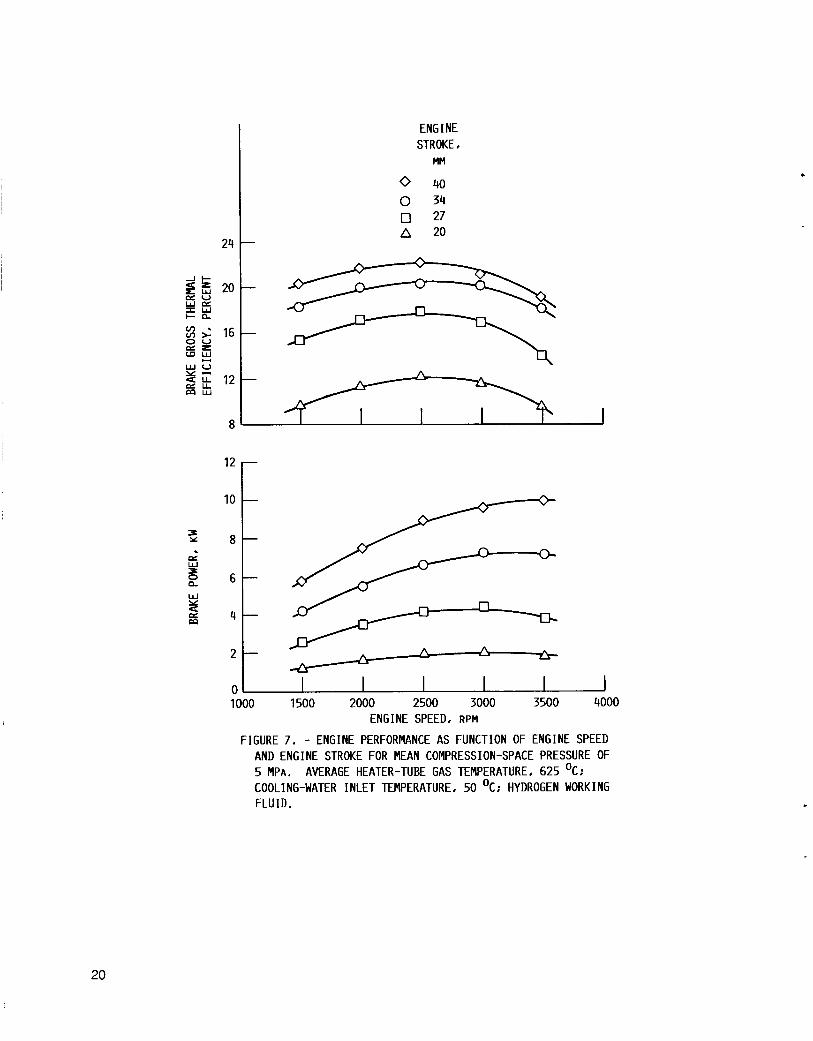
Performance t e s t i n g was then s t a r t e d w i t h hydrogen w o r k i n g f l u i d . The engine was t e s t e d o v e r t h e range of engine s t r o k e s o f 20 to 40 mm f o r mean compression-space p ressu res of 3 and 5 MPa and a t s t r o k e s o f 20 and 27 mm a t 7 MPa pressure. compression-space p ressu res o f 3, 5, and 7 MPa a r e shown i n f i g u r e s 6, 7 , and 8, r e s p e c t i v e l y . was 10.0 kW f o r a 5-MPa mean compression-space p r e s s u r e , a 40-mm eng ine s t r o k e , and a 3500-rpm engine speed. The maximum b rake g ross thermal e f f i c i e n c y was 22.1 p e r c e n t f o r t h e same p ressu re and s t r o k e b u t f o r an eng ine speed o f 2500 rpm. thermal e f f i c l e n c y a r e i n c l u d e d i n the appendix.
Brake power and brake gross thermal e f f i c i e n c y fo r mean
The maximum brake power measured d u r i n g these hydrogen t e s t s
Error analyses for t h e measurements o f b rake power and brake gross
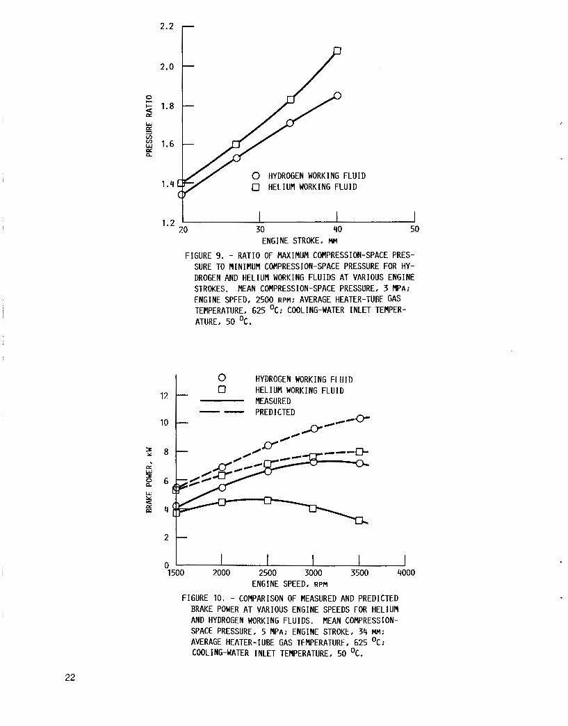
Represen ta t i ve engine pressure r a t i o s o b t a i n e d w i t h h e l i u m and hydrogen work ing f l u i d s a r e shown i n f i g u r e 9. The p ressu re r a t i o i s t h e maximum compression-space p ressu re d i v i d e d by t h e minimum compression-space p ressu re . The minimum and maximum p ressu res were measured i n t h e p r e s s u r i z a t i o n and v e n t l i n e s connec t ing t h e f o u r c y c l e s . These l i n e s were i s o l a t e d from t h e working- f l u i d c y c l e s by check va l ves ; t h e check-valve a c t i o n causes t h e minimum and maximum c y c l e p ressu res to be s to red i n t h e p r e s s u r i z a t i o n and v e n t l i n e s , r e s p e c t i v e l y.
Comparisons o f t h e t e s t d a t a w i t h computer p r e d i c t i o n s i n d i c a t e t h a t t h e exper imen ta l va lues o f power and e f f i c i e n c y a r e lower than was a n t i c i p a t e d . T h i s i s shown i n f i g u r e 10, which compares t h e p r e d i c t e d b rake power w i t h meas- u red va lues for b o t h hydrogen and he l i um work ing f l u i d s . The p r e d i c t i o n s were generated w i t h t h e NASA Lewis S t i r l i n g engine computer s i m u l a t i o n d e s c r i b e d i n r e f e r e n c e 4. The d i f f e r e n c e s between measured and p r e d i c t e d b rake power c o u l d p a r t l y be due t o higher- than-expected mechanical l o s s e s , as ev idenced by t h e d r i ve -sys tem f a i l u r e s (see t h e s e c t i o n "Drive-System F a i l u r e s " ) and by exces- s i v e amounts o f h e a t r e j e c t e d to the o i l l u b r i c a n t . A comparison o f t h e p re - d i c t e d mechanical l osses w i t h t h e heat r e j e c t e d t o t h e o i l i s shown i n f i g u r e 11 f o r o p e r a t i o n a t 5-MPa p ressu re and 34-mm engine s t r o k e and w i t h hydrogen work ing f l u i d . The hea t r e j e c t e d t o t h e o i l was g r e a t e r t han t h e t o t a l p re - d i c t e d mechanical l osses ; t h e p r e d i c t e d mechanical l o s s e s a l s o i n c l u d e p i s t o n r i n g f r i c t i o n t h a t r e p r e s e n t s hea t t h a t i s n o t r e j e c t e d t o t h e o i l l u b r i c a n t . I t appears, then, t h a t t h e a c t u a l mechanical l osses were much g r e a t e r t han those used to generate t h e p r e d i c t i o n s . These unknown mechanical l osses make comparisons w i t h computer s i m u l a t i o n p r e d i c t i o n s d i f f i c u l t a t b e s t .
The da ta were used t o eva lua te p o s s i b l e p a r t - l o a d e f f i c i e n c y ga ins w i t h v a r i a b l e stroke. F i g u r e s 12 and 1 3 compare brake gross thermal e f f i c i e n c i e s a t p a r t loads o b t a i n e d by v a r y i n g the s t r o k e a t c o n s t a n t p r e s s u r e and by v a r y i n g t h e p ressu re a t c o n s t a n t stroke f o r hydrogen and h e l i u m work ing f l u - i d s , r e s p e c t i v e l y . , I n b o t h f i g u r e s , t h e v a r y i n g s t r o k e curves a r e p l o t t e d for a cons tan t p ressu re o f 5 MPa. I n f i g u r e 12, t h e v a r y i n g p r e s s u r e curves
5

f o r hydrogen a re f o r a cons tan t s t r o k e of 40 mm; f o r t h e h e l i u m cu rves o f f i g - u r e 13, t h e constant s t r o k e was 34 mm. The h e l i u m d a t a were taken p r i o r t o the f i r s t dr ive-system f a i l u r e .
For t h e l i m i t e d amount o f t e s t d a t a a v a i l a b l e , t h e e f f i c i e n c i e s o b t a i n e d w i t h hydrogen working f l u i d a t t h e lower engine speeds a r e i d e n t i c a l for b o t h v a r i a b l e - s t r o k e and v a r i a b l e - p r e s s u r e o p e r a t i n g modes. A t t h e h i g h e r engine speeds, t h e v a r i a b l e - s t r o k e mode shows some improvement i n t h e p a r t - l o a d e f f i - c i ency . However, f o r t h e au tomot i ve a p p l i c a t i o n , l i t t l e e f f i c i e n c y g a i n would be r e a l i z e d because t h e m a j o r i t y o f o p e r a t i o n i s a t t h e l ower engine speeds. I n f i g u r e 13, t h e v a r i a b l e - s t r o k e mode w i t h h e l i u m work ing f l u i d compared w i t h the va r iab le -p ressu re mode shows a g r e a t e r improvement than f o r t h e hydrogen curves.
The e f f i c i e n c y improvements for v a r i a b l e - s t r o k e o p e r a t i o n compared w i t h the va r iab le -p ressu re mode a t t h e same power l e v e l a r e due i n p a r t t o lower f low l o s s e s through t h e h e a t exchangers f o r a g i v e n p a r t - l o a d p o i n t . T h i s was p r e d i c t e d by t h e NASA Lewis S t i r l i n g engine computer s i m u l a t i o n . I n a d d i t i o n , heat l osses t h a t tend t o decrease w i t h reduced s t r o k e and p ressu re r a t i o (such as s h u t t l e losses) c o n t r i b u t e to t h i s improvement i n e f f i c i e n c y . The l a r g e r d i f f e r e n c e between t h e v a r i a b l e - s t r o k e and v a r i a b l e - p r e s s u r e modes for h e l i u m work ing f l u i d (compared w i t h hydrogen) may be reduced i n an engine t h a t was designed f o r hel ium ( f o r example, hea t exchangers designed for lower flow l o s s e s ) .
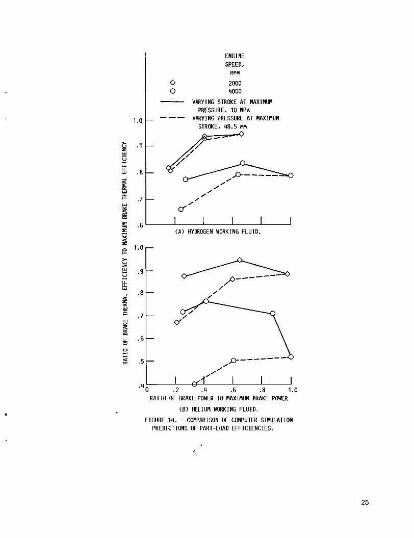
The t e s t data used i n f i g u r e s 12 and 13 were r e s t r i c t e d to t h e l ower power l e v e l s . The NASA Lewis S t i r l i n g engine computer s i m u l a t i o n was used t o generate s i m i l a r comparisons a t t h e maximum s t r o k e o f 48.5 mm and t h e maximum p ressu re o f 10 MPa. These comparisons a r e shown i n f i g u r e 14. For these curves, t h e maximum b rake power (1 .0 on x -ax i s ) was 43.2 kW f o r hydrogen and 24.2 kW f o r hel ium. The maximum brake thermal e f f i c i e n c y (1.0 on y - a x i s ) (does n o t i n c l u d e bu rne r l osses ) was 45 p e r c e n t f o r hydrogen and 40 p e r c e n t f o r hel ium. The same types o f v a r i a t i o n s seen w i t h speed and between hydrogen and h e l i u m i n f i g u r e 14 were o b t a i n e d fo r t h e a c t u a l t e s t d a t a shown i n f i g u r e s 12 and 13.
A v a r i a b l e - s t r o k e engine i s i n tended t o o p e r a t e c o n s t a n t l y a t i t s maximum working-space pressure. Thus, for t h e same des ign l i f e , i t s p ressu re vesse l w a l l s tend t o be t h i c k e r than those f o r a mean-pressure c o n t r o l engine w i t h the same maximum pressure. Th is should g i v e somewhat lower conduc t ion l osses f o r t he comparable mean-pressure c o n t r o l engine; f i g u r e s 12 th rough 14 have n o t been a d j u s t e d f o r t h i s . I t i s n o t a n t i c i p a t e d t h a t t h i s c o r r e c t i o n would be s i g n i f i c a n t or change the conc lus ions based on t h e r e s u l t s o b t a i n e d .
The t e s t i n g w i t h hydrogen work ing f l u i d was ended by ano the r d r i ve -sys tem f a i l u r e , t h i s one much l e s s severe than t h e f i r s t f a i l u r e . T h i s second f a i l - u re occu r red wh i l e r u n n i n g a t 7-MPa p ressu re and a 1500-rpm engine speed w h i l e i n c r e a s i n g the s t roke from 27 t o 34 mm. Approx ima te l y 45 h r of eng ine t e s t i n g w e r e accomplished w i t h t h e engine a f t e r t h e r e b u i l d i n g f o l l o w i n g t h e f i r s t f a i l u r e . Both engine f a i l u r e s a r e rev iewed i n t h e f o l l o w i n g s e c t i o n .
6
Drive-System Fai l u r e s
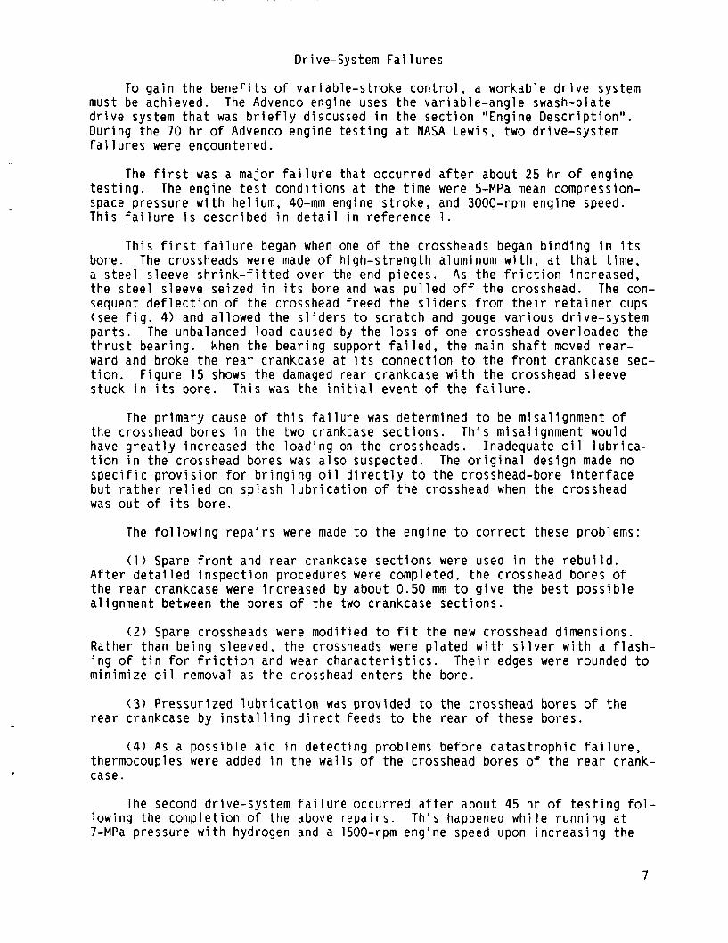
To g a i n t h e b e n e f i t s o f v a r i a b l e - s t r o k e c o n t r o l , a workable d r i v e system must be achieved. The Advenco engine uses t h e v a r i a b l e - a n g l e swash-plate d r i v e system t h a t was b r i e f l y discussed i n t h e s e c t i o n "Engine D e s c r i p t i o n " . Dur ing t h e 70 h r o f Advenco engine t e s t i n g a t NASA Lewis, two d r i ve -sys tem f a i l u r e s were encountered.
The f i r s t was a major f a i l u r e t h a t o c c u r r e d a f t e r about 25 h r of engine t e s t i n g . space p ressu re w i t h he l ium, 40-mm engine s t r o k e , and 3000-rpm engine speed. This f a i l u r e i s desc r ibed i n d e t a i l i n r e f e r e n c e 1 .
The engine t e s t c o n d i t i o n s a t t h e t i m e were 5-MPa mean compression-
Th is f i r s t f a i l u r e began when one o f t h e crossheads began b i n d i n g i n i t s bore. The crossheads were made of h i g h - s t r e n g t h aluminum w i t h , a t t h a t t ime , a s t e e l s leeve s h r i n k - f i t t e d o v e r the end p ieces . A s t h e f r i c t i o n i nc reased , t h e s t e e l s leeve se i zed i n i t s bore and was p u l l e d o f f t h e crosshead. The con- sequent d e f l e c t i o n o f t h e crosshead f reed t h e s l i d e r s from t h e i r r e t a i n e r cups (see f i g . 4) and a l l owed t h e s l i d e r s to s c r a t c h and gouge v a r i o u s d r i ve -sys tem p a r t s . The unbalanced l o a d caused by t h e l o s s o f one crosshead ove r loaded t h e t h r u s t bear ing. ward and broke t h e r e a r crankcase a t i t s connec t ion to t h e f r o n t crankcase sec- t i o n . F i g u r e 15 shows t h e damaged r e a r crankcase w i t h t h e crosshead s leeve s t u c k i n i t s bore. T h i s was the i n i t i a l even t o f t h e f a i l u r e .
When t h e b e a r i n g support f a i l e d , t h e main s h a f t moved r e a r -
The p r i m a r y cause o f t h i s f a i l u r e was determined t o be m isa l i gnmen t o f t h e crosshead bores i n t h e two crankcase s e c t i o n s . T h i s m isa l i gnmen t would have g r e a t l y i nc reased t h e l o a d i n g on t h e crossheads. Inadequate o i l l u b r i c a - t i o n i n t h e crosshead bores was a l s o suspected. The o r i g i n a l des ign made no s p e c i f i c p r o v i s i o n for b r i n g i n g o i l d i r e c t l y t o t h e crosshead-bore i n t e r f a c e b u t r a t h e r r e l i e d on sp lash l u b r i c a t i o n o f t h e crosshead when t h e crosshead was o u t o f i t s bore.
The f o l l o w i n g r e p a i r s were made t o t h e engine t o c o r r e c t these problems:
( 1 ) Spare f r o n t and r e a r crankcase s e c t i o n s were used i n t h e r e b u i l d . A f t e r d e t a i l e d i n s p e c t i o n procedures were completed, t h e crosshead bores o f t h e r e a r crankcase were i nc reased by about 0.50 mm t o g i v e t h e b e s t p o s s i b l e a l i gnmen t between t h e bores o f t h e two crankcase s e c t i o n s .
( 2 ) Spare crossheads w e r e m o d i f i e d t o f i t t h e new crosshead dimensions. Rather than b e i n g sleeved, the crossheads were p l a t e d w i t h s i l v e r w i t h a f l a s h - i n g o f t i n for f r i c t i o n and wear c h a r a c t e r i s t i c s . m in im ize o i l removal as t h e crosshead e n t e r s t h e bore.
T h e i r edges were rounded to
(3 ) P r e s s u r i z e d l u b r i c a t i o n was p r o v i d e d t o the crosshead bores o f t h e r e a r crankcase by i n s t a l l i n g d i r e c t feeds t o t h e r e a r o f these bo res .
( 4 ) A s a p o s s i b l e a i d i n d e t e c t i n g problems b e f o r e c a t a s t r o p h i c f a i l u r e , thermocouples were added i n t h e w a l l s o f t h e crosshead bores o f t h e r e a r crank- case.
The second d r i ve -sys tem f a i l u r e o c c u r r e d a f t e r about 45 h r o f t e s t i n g f o l - l ow ing the comp le t i on o f the above r e p a i r s . Th i s happened w h i l e r u n n i n g a t 7-MPa p ressu re w i t h hydrogen and a 1500-rpm engine speed upon i n c r e a s i n g t h e
7

stroke t o 34 mm. One o f t h e crossheads momentar i ly se i zed i n i t s bo re and then f r e e d i t s e l f , a l l o w i n g t h e engine t o be s a f e l y motored t o a s t o p . The damage t o t h e engine was p r i m a r i l y l i m i t e d t o t h i s one crosshead and i t s two bores.
Two views o f t h e f a i l e d crosshead a r e shown i n f i g u r e 16. Removal o f t h e s i l v e r p l a t i n g can c l e a r l y be seen on t h e r i g h t end o f t h e crosshead; t h i s end r i d e s i n t h e bore o f t he r e a r crankcase. A n a l y s i s o f t h e f a i l u r e i n d i c a t e d t h e cause to be wear i n t h e s i l v e r p l a t i n g and/or a bonding f a i l u r e o f a plasma-sprayed aluminum c o a t i n g used to b u i l d up t h e o u t e r d iamete r o f t h e r e a r end o f t h e crosshead ( b e f o r e t h e s i l v e r was a p p l i e d ) . The d iamete r o f t h e crosshead had t o be i nc reased because o f t h e need f o r e n l a r g i n g t h e r e a r crankcase bores t o p r o v i d e t h e b e s t p o s s i b l e a l i gnmen t . The l a r g e c h i p o f f t h e extreme r i g h t end of t h e crosshead i n t h e upper pho to shows removal o f t h e aluminum c o a t i n g and t h e s i l v e r p l a t i n g . Wear p a t t e r n s i n t h e s i l v e r were a l s o e v i d e n t on the o t h e r t h r e e crossheads; these c o u l d have r e s u l t e d from t h e f a i l u r e or from t h e wear d u r i n g t h e 45 h r o f t e s t i n g . a re shown i n f i g u r e 17 .
These t h r e e crossheads
The o n l y o the r damage found was a r o t a t i o n , w i t h r e s p e c t t o t h e main s h a f t , o f t h e t i l t e d hub around which t h e swash p l a t e r o t a t e s t o change i t s ang le . Th is r o t a t i o n caused a decrease i n t h e minimum s t r o k e o f t h e engine.
Because o f t h e n a t u r e o f t h e crosshead p l a t i n g and p o s s i b l y because o f t h e r e l i e v i n g a c t i o n o f t h e t i l t e d h u b ' s r o t a t i o n , t h i s f a i l u r e was n o t as sud- den as t h e f i r s t f a i l u r e and caused much l e s s damage. Also o f i n t e r e s t was the response o f t h e thermocouples i n t h e w a l l s o f t h e crosshead bo res . The w a l l temperature o f t h e f a i l e d bore rose about 120 "C d u r i n g t h e f a i l u r e ; t h i s should be s u f f i c i e n t to a l l o w these thermocouples t o be used for au tomat i c shutdowns.
CONCLUDING REMARKS
For automot ive a p p l i c a t i o n s , v a r i a b l e - s t r o k e power c o n t r o l o f f e r s reduced c o n t r o l system complex i ty . However, t o achieve t h i s b e n e f i t , a workable d r i v e system must be obta ined. I t i s n o t t hough t t h a t t h e f a i l u r e s a t NASA Lewis w i t h the Advenco engine i n d i c a t e any i n h e r e n t problems w i t h t h e v a r i a b l e - s t r o k e concept but r a t h e r t h a t these f a i l u r e s w e r e r e l a t e d t o r e s t r i c t i o n s o f a hardware- and d o l l a r - l i m i t e d program. However, t h e f a i l u r e s do emphasize t h e need f o r ca re fu l des ign i n t h e a rea o f t h e crossheads. The crossheads r e q u i r e p r o p e r l y a l i g n e d bores and t h e c a r e f u l s e l e c t i o n o f compa t ib le m a t e r i - a l s for the crosshead and bo re t h a t can meet t h e requ i remen ts o f l i f e and engi ne balance.
From t h e l i m i t e d t e s t d a t a t h a t were ob ta ined , o n l y a smal l b e n e f i t , i f any, c o u l d be expected i n part-power e f f i c i e n c y f o r au tomot i ve a p p l i c a t i o n s t h a t r e q u i r e o p e r a t i o n p r i m a r i l y a t low engine speeds. An a p p l i c a t i o n t h a t r e q u i r e s s u b s t a n t i a l high-speed o p e r a t i o n as w e l l as o p e r a t i o n o v e r a range of loads may b e n e f i t t o a g r e a t e r e x t e n t .
A f t e r a review of t h e l a s t f a i l u r e , Advenco t e s t i n g a t NASA Lewis was stopped. Budget and manpower 1 i m i t a t i o n s w e r e t r a d e d o f f w i t h t h e p robab i 1 i t y o f a c h i e v i n g enhanced performance i n a l i m i t e d t i m e w i t h t h e a v a i l a b l e hard- ware. t r o l system. Though no f u r t h e r work i s planned, NASA Lewis does c o n t i n u e
Also, s a t i s f a c t o r y p rog ress was b e i n g made w i t h t h e mean-pressure con-
8
to have an interest in the variable-stroke concept. Development by manufacturer o f a more advanced version of a variable-stroke engine varlable-angle swash-plate drive will be followed with interest. A reliability o f the mean-pressure control system will continue to be
a private using a so, the moni tored.
9

APPENDIX - ERROR ANALYSIS FOR HEAT INPUT, BRAKE POWER, AND BRAKE
GROSS THERMAL EFFICIENCY
An error a n a l y s i s was done t o determine t h e accuracy of t h e measured h e a t i n p u t , brake power, and b rake gross thermal e f f i c i e n c y . I n c l u d e d i n t h i s appendix a re a l i s t i n g o f t h e measurement accu rac ies , sample c a l c u l a t i o n s o f t h e u n c e r t a i n t i e s , and t h e r e s u l t s for r e p r e s e n t a t i v e high-power and low-power d a t a p o i n t s . n a l l y t o see which measurements c o u l d be improved t o decrease c a l c u l a t i o n u n c e r t a i n t i e s and a l s o t o understand these e f f e c t s on t h e r e p e a t a b i l i t y o f t h e da ta . i n t h i s r e p o r t . The methane f u e l system was i n s t a l l e d and a lower range flow- meter f o r the f u e l was purchased. The c a l c u l a t i o n s shown i n t h i s appendix i n - d i c a t e t h e f i n a l r e s u l t s a f t e r t h e f a c i l i t y m o d i f i c a t i o n s .
An error a n a l y s i s f o r t h e Advenco S t i r l i n g engine was done o r i g i -
The error a n a l y s i s l e d t o some o f t h e f a c i l i t y m o d i f i c a t i o n s ment ioned
For each measurement, t h e root-mean-square (rms) method was chosen t o sum t h e i n d i v i d u a l e r r o r s i n s e r i e s from t h e i n s t r u m e n t i t s e l f t o t h e r e c o r d i n g system. The measurement accu rac ies a r e l i s t e d i n t a b l e I. Sample c a l c u l a - t i o n s o f t h e u n c e r t a i n t i e s i n t h e hea t i n p u t , b rake power, and brake gross thermal e f f i c i e n c y a r e shown f o r a high-power d a t a p o i n t . i n g c o n d i t i o n s for t h i s d a t a p o i n t a r e l i s t e d i n t a b l e 11.
The engine o p e r a t -
The r e s u l t s o f t h e e r r o r a n a l y s i s a r e g i v e n i n t a b l e 111 for two represen- t a t i v e d a t a p o i n t s - t h e high-power p o i n t (10 kW) used i n t h e sample c a l c u l a - t i o n s , and a low-power p o i n t ( 2 kW). The engine o p e r a t i n g c o n d i t i o n s for b o t h p o i n t s a r e l i s t e d i n t a b l e 11. These r e s u l t s i n d i c a t e t h a t t h e u n c e r t a i n t i e s f o r t h e h i g h e r power d a t a a r e reasonable, w i t h l a r g e r u n c e r t a i n t i e s a s s o c i a t e d w i t h the low-power p o i n t s . I t should be no ted t h a t t h e maximum power o b t a i n e d d u r i n g t h e Advenco t e s t i n g was o n l y about 25 p e r c e n t o f t h e des ign o u t p u t .
The s tandard c a l c u l a t i o n t h a t was used f o r f i n d i n g t h e u n c e r t a i n t y i s g i v e n by the f o l l o w i n g e q u a t i o n ( r e f . 5 ) :
1 / 2
W R = [(c w l y + (c w2)z + . . . + (q ..)'I where W R u n c e r t a i n t y i n the r e s u l t R
x i , x2, . . . x n independent v a r i a b l e s w1 , w2*. . .w, u n c e r t a i n t i e s i n t h e independent v a r i a b l e s
( 1 )
Sample c a l c u l a t i o n s ( for t h e high-power p o i n t l i s t e d i n t a b l e 11) a r e as fol lows:
Pwr in = Fflom LHV 4.184
10
Heat I n p u t
( 2 )

where
Pwrln power into the engine, kW
Fflom fuel flow, g/sec
LHV lower heating value of the fuel, kcal/g For methane, LHV = 11.955
1 /2
'Pwr i n aPwrin aFflom Fflom 7 + (- "LHV7]
= LHV 0 4.184 aFf 1 om
= Fflom 4.184 aLHV
= (full-scale fuel-flow measurement) (measurement accuracy) Ff lom W
= 2.16 g/sec (0.010)
= 0.0216 g/sec
= 11.955 kcal/g (0.010) 'LHV
= 0.11 955 kcal /g
)' + (Fflom 4.184 wLHV )2] I2 = [(LHV 4.184 wFflom 'pwr i n
112 = [(11.955: 4.184 0.0216)2 + (1.05 4.184 0.11955)2]
(3)
(4)
(5)
(6)
( 7 )
(8 )
= 21.2 kW Measured power into the engine = 52.3 kW (9) 'Pwr i n
Percent error = 22.3
Brake Power
Pwrout = Torq2 RPM/9459.3 (10)
1 1

where
Pwrout brake power, kW
Torq2 engine torque, N-m
RPM engine speed, rpm
aPwrout - RPM aTorq2 - 9549.3
aPwrout - Torq2 aRPM - 9549.3
(12)
(13)
= (full-scale torque measurement) (measurement accuracy) Torq2 W
= 101.7 N-m (0.0061)
= 0.6 N-m (14)
= (full-scale engine speed measurement) (measurement accuracy)
= 6000 rpm (0.0014) 'RPM
= 8.5 rpm (15)
'Pwrout = [(9549.3 RPM 0 w Torq27 + (m 'RPM 1 / 2
- - [(m 9549.3 0.6r + ( 9549.3 27'3 8.5)2]
W Pwrout = 20.2 kW Measured brake power = 10.0 kW
Percent error = *2.0
Brake Gross Thermal Efficiency
Brkeff = Pwrout 100/Pwrin
(18)
( 1 6 )
(17)
12

where
B r k e f f brake g ross thermal e f f i c i e n c y , p e r c e n t
Pwrout brake power, kW
Pwr in power i n t o t h e engine, kW
aBrke f f aPwrou t Pwrou t
a B r k e f f W B r k e f f = [(aPwrin 'Pwr i n
a B r k e f f -100 Pwrout
a P w r i n Pwr in 2 - -
3 B r k e f f - 100 aPwrou t P w r i n
-
= 0.2 kW (from above) 'Pwrout
= 1.2 kW (from above) 'Pwrin
-100 Pwrout 'B rke f f = [( 2 'Pwr i n P w r i n 'Pwrou t
P w r i n
'1 "2
= [(-1005;.;;.o 0 1.2) + (m 100 0.2)
20.6 percentage p o i n t s Measured brake g ross thermal e f f i c i e n c y = 19.1 p e r c e n t 'B rke f f =
(19)
(20)
(21)
(22)
(23)
( 2 4 )
(25)
Percen t e r r o r = 23.1
13

REFERENCES
1 . Thieme, L.G.: I n i t i a l T e s t i n g o f a V a r i a b l e - S t r o k e DOE/NASA/51040-58, NASA TM-86875, 1985.
I
S t i r l i n g Engine.
2 . Vos, J . : Design C h a r a c t e r i s t i c s o f an Advanced S t r l i n g Engine Concept I n Proceedings of t h e 1 4 t h I n t e r s o c i e t y Energy Convers ion E n g i n e e r i n g Con- fe rence , Vol. 1 , American Chemical S o c i e t y , Washington, D.C., 1979, pp. 1191-1196.
3 . M e i j e r , R.J.; and Z iph, 6 . : V a r i a b l e S t r o k e Power C o n t r o l for S t i r l i n g
4. Tew, Roy C., J r . : Computer Program f o r S t i r l i n g Engine Performance
Engines. SAE Paper 810088, 1981.
C a l c u l a t i o n s . DOE/NASA/51040-42, NASA TM-82960, 1983.
5 . Holman, J.P: Exper imenta l Methods f o r Engineers, 2nd e d i t i o n , McGraw-Hi l l , New York, 1971, p. 38.
TABLE I. - MEASUREMENT ACCURACIES I N PERCENT
Torque ( l o a d c e l l ) Load c e l l system . . . . . . . . . . . . . . . . . . . . 0.6 Escort r e c o r d i n g system . . . . . . . . . . . . . . . . 0 . 1 RMS va lue . . . . . . . . . . . . . . . . . . . . . . . 0.61
Flowmeter . . . . . . . . . . . . . . . . . . . . . . . 1 . O Escort r e c o r d i n g system . . . . . . . . . . . . . . . . 0.1 RMS va lue . . . . . . . . . . . . . . . . . . . . . . . 1 .O
Frequency-to-dc conver te r . . . . . . . . . . . . . . . 0.1 Escort r e c o r d i n g system . . . . . . . . . . . . . . . . 0.1 RMS va lue . . . . . . . . . . . . . . . . . . . . . . . 0.14
Methane . . . . . . . . . . . . . . . . . . . . . . . . 1 .O
Fuel f l o w (mass f lowmeter )
Engine speed (magnet ic p i ckup )
Lower h e a t i n g va lue ( f u e l )
TABLE 11. - ENGINE OPERATING CONDITIONS
[Fue l , methane; work ing f l u i d hydrogen. 1
Opera t ing c o n d i t i o n s
Engine speed, rpm Average hea te r gas temperature, "C Cool ing water i n l e t temperature, "C Engine to rque, N-m Mean pressure, MPa Engine s t roke , mm Fuel f l ow , g/sec Power i n t o t h e engine, kW Brake power, kW Brake gross thermal e f f i c i e n c y , pe rcen t
I Hi gh-power p o i n t
3507 623 49
27.3 5.05 40.0 1.05 52.3 10.0 19.1
Low-power
5.03 20.2 0.35 17.5 2.0
11.5
14

ORIGINAL PAGE md POOR QUALm TABLE III. - UNCERTAINTY RESULTS FOR REPRESENTATIVE
HIGH-POWER AND LOW-POWER DATA POINTS
( a ) Power i n t o t h e engine
I I Power i n t o I U n c e r t a i n t y i n I E r r o r , I t h e engine, t he measurement, pe rcen t
kW I kW I H i gh-power 52.3 1.2 2.3
Low-power 17.5 1.1 6.3 da ta p o i n t
da ta p o i n t
( b ) Brake power
Brake power, U n c e r t a i n t y i n E r r o r , kW t h e measurement, pe rcen t
kW
High-power 10.0 0.2 2 .0
Low-power 2.0 0.2 10.0 da ta p o i n t
da ta p o i n t
( c ) Brake gross thermal e f f i c i e n c y
Brake gross U n c e r t a i n t y in
e f f i c i e n c y , percentage p o i n t s
E r r o r , thermal t h e measurement, pe rcen t
percent
I 3 * 1 I 11.3
Hi gh-power I 19.1 I d a t a p o i n t
d a t a p o i n t Low-power 11.5 1.3
F IGURE 1. - ADVENCO S T I R L I N G ENGINE.
15

FIGURE 2. - ADVENCO STIRLING ENGINE CROSS SECTION.
ORlGlNAL PAGE IS OF POOR QUALIW
16

ORIGINAL PAGE IS OF PQOR QUALtTY
FIGURE 3. - VARIABLE-ANGLE SWASH-PLATE ASSEMBLY.
FIGURE 4. - PISTON, ROLLSOCK CARTRIDGE AND SEAL, AND CROSSHEAD WITH SLIDERS.
17

ENGINE STROKE,
MM
0 34 0 27 A 20
v , . v,> o u C L T
$ 2 < L C L L
4
1 2 -
8 -
I I I
YO00 1500 2000 2500 3000 3500 4000 ENGINE SPEED, RPM
FIGURE 5. - ENGINE PERFORMANCE AS FUNCTION OF ENGINE SPEED AND ENGINE STROKE FOR MEAN COMPRESSION-SPACE PRESSURE OF 5 MPA. COOLING-WATER INLET TEMPERATURE, 50 OC; HELIUM WORKING FLUID.
AVERAGE HEATER-TUBE GAS TEMPERATURE, 625 OC:
18
ENGINE STROKE,
MM
0 40 0 34 0 27 A 20
- I I 1
0 1 I I I I I I
5 f 2
U
' I 7 ENGINE SPEED, RPM
FIGURE 6. - ENGINE PERFORMANCE AS FUNCTION OF ENGINE SPEED AND ENGINE STROKE FOR MEAN COMPRESSION-SPACE
ATURE, 625 OC; COOL I NG-WATER INLET TEMPERATURE, 50 OC; HYDROGEN WORKING FLUID.
PRESSURE OF 3 MPA. AVERAGE HEATER-TUBE GAS TEMPER-
19
10 -
3 8 -
Y n 6 -
0:
0
W Y 4 = 4 - m
2 -
ENGINE STROKE,
MM
0 40 0 34 0 27 A 20
01 I I I I I 1000 1500 2000 2500 3000 3500 4000
ENGINE SPEED, RPM
FIGURE 7. - ENGINE PERFORMANCE AS FUNCTION OF ENGINE SPEED AND ENGINE STROKE FOR MEAN CONPRESSION-SPACE PRESSURE OF 5 \PA. AVERAGE HEATER-TUBE GAS TEMPERATURE. 625 OC; COOLING-WATER INLET TEMPERATURE, 50 OC; HYDROGEN WORKING FLUID.
20

20% 16
6 .
4 '
2
ENGINE STROKE,
MM
0 27 A 20
8 /
01 I I I I I I 1000 1500 2000 2500 3000 3500 4000
ENGINE SPEED, RPM
FIGURE 8. - ENGINE PERFORMANCE AS FUNCTION OF ENGINE SPEED AND ENGINE STROKE FOR MEAN COMPRESSION-SPACE PRESSURE OF 7 RPA. AVERAGE HEATER-TUBE GAS TEMPER- ATURE, 625 OC: COOLING-WATER INLET TEMPERATURE, 50 OC: HYDROGEN WORKING FLUID.
21
2 * 2 r P 2.0 t /
0, s !-
W e v) v) W e Q
a
1.8
1.6
1 . 4 0 HYDROGEN WORKING FLUID 0 HELIUM WORKING FLUID c
C
3 30 40 50 1.2
20 ENGINE STROKE. MM
FIGURE 9. - RATIO OF MAXIMUM COMPRESSION-SPACE PRES- SURE TO MINIMUM COMPRESSION-SPACE PRESSURE FOR HY- DROGEN AND HELIUM WORKING FLUIDS AT VARIOUS ENGINE STROKES. ENGINE SPEED, 2500 RPM: AVERAGE HEATER-TUBE GAS TEMPERATURE, 625 OC: COOLING-WATER INLET TEMPER- ATURE, 50 OC.
MEAN COMPRESSION-SPACE PRESSURE, 3 MPA:
0 HYDROGEN WORKING FLUID HELIUM WORKING FLUID MEASURED 12
10
CT W
$ 6 W Y s c p 4
-- PREDICTED
1500 2000 2500 3000 3500 4000 0
ENGINE SPEED, R P M
FIGURE 10. - COMPARISON OF MEASURED AND PREDICTED BRAKE POWER AT VARIOUS ENGINE SPEEDS FOR HELIUM AND HYDROGEN WORK I NG FLU IDS , MEAN COMPRESSION- SPACE PRESSURE, 5 MPA: ENGINE STROKE, 34 MM: AVERAGE HEATER-TUBE GAS TEMPERATURE, 625 OC : COOLING-WATER INLET TEMPERATURE. 50 OC.
22

I 0 PREDICTED LOSSES 3.0
2.5
07 2.0
1.5
v) W v)
OJ J
L
52 2: 1.0 E
.5
L 0 MEASURED HEAT TO OIL - 0 MEASURED HEAT TO O I L
c c
0 1500 2000 2500 3000 3500 4000
ENGINE SPEED. RPM
FIGURE 11.- COMPARISON OF MEASURED HEAT REJECTION TO O I L LUBRICANT WITH PREDICTED MECHANICAL LOSSES FOR VARIOUS ENGINE SPEEDS. MEAN COMPRESSION-SPACE PRES- SURE, 5 MPA; ENGINE STROKE, 34 MM: AVERAGE HEATER- TUBE GAS TEMPERATURE, 625 OC; COOL ING-WATER INLET TEMPERATURE, 50 OC; HYDROGEN WORKING FLUID.
SPEED. RPM
A 2000 - 0 3500
VARY I NG STROKE -- VARYING PRESSURE
2 4 6 8 lo BRAKE POWER. KW
FIGURE 12. - COMPARISON OF EFFICIENCIES AT PART LOAD OB-
ING PRESSURE AT 40 STROKE; HYDROGEN WORKING FLUID. TAINED BY VARYING STROKE AT 5 MPA PRESSURE AND BY VARY-
23

SPEED *
A 2000 0 3000
RPM
VARYING STROKE --- VARYING PRESSURE
a & a 0 1 2 3 4 5
BRAKE POWER, KW
FIGURE 13. - COMPARISON OF E F F I C I E N C I E S AT PART LOAD OB- TAINED BY VARYING STROKE AT 5 MPA PRESSURE AND BY VARY- ING PRESSURE AT 34 STROKE; HELIUM WORKING F L U I D .
.
24
I
1 .o
.9
. a
.?
ENGINE SPEED, uPn
0 2000 0 4000
VARYING STROKE AT MAXIMUM PRESSURE, 10 MPA
STROKE. 48.5 MM
- VARYING PRESSURE AT MAXIMUM
0’
I I I I I . E (A) HYDROGEN WORKING FLUID.
r .9
.8
.7
.6
. 5
25

26
C-82-6697
FIGURE 15. - DAMAGED REAR CRANKCASE FROM F IRST DRIVE-SYSTEM F A I L - URE: NOTE CROSSHEAD SLEEVE STUCK I N BORE.
C-85-6862
FIGURE 16. - TWO VIEWS OF FAILED CROSSHEAD FROM SECOND DRIVE-SYSTEM FAILURE.

.
t
ORIGINAL FASE IS OF POOR QUALW
FIGURE 17. - THREE CROSSHEADS NOT PRIMARILY INVOLVED IN SECOND DRIVE-SYSTEM FAILURE.
27

National Aeronautics and
1. Report No D O E / N A S A / ~ ( ) ~ 12-75 NASA TM-100899
Report Documentation Page 2 Government Accesslon No
19. Security Classif. (of this report)
4. Title and Subtitle
T e s t i n g o f a Var iab le -S t roke Stir1 i n g Engine
22. Price' 20. Security Classif. (of this page) 21. No of pages
7. Author(s)
Lanny G. Thieme and Dav id J . A l l e n
Uncl a s s i f i ed
9. Performing Organization Name and Address N a t i o n a l Aeronaut ics and Space A d m i n i s t r a t i o n Lewis Research Center C1 eve1 and , Oh io 441 35-31 91
U n c l a s s i f i e d 28 A03 I
2. Sponsoring Agency Name and Address
U . S . Department o f Energy O f f i c e o f V e h i c l e and Engine R&D Washington, D.C. 20545
3. Recipient's Catalog No.
5. Report Date
6. Performing Organization Code
8. Performing Organization Report No.
E-3056
10. Work Unit No.
778-35-1 3
11. Contract or Grant No.
13. Type of Report and Period Covered
Techn ica l Memorandum 14. Sponsoring Agency Code
5 . Supplementary Notes F i n a l Report . Research Center and David J . A l l e n , Sverdrup Technology, I n c . . NASA Lewis Research Center Group, C leve land , Ohio 44135. Prepared f o r the 2 1 s t I n t e r s o c i e t y Energy Conversion Engineering Conference ( IECEC), cosponsored by t h e A C S , SAE, ANS. ASME, IEEE, A I A A , and AIChE, San Diego, C a l i f o r n i a ,
Prepared under Interagency Agreement DE-AI01-85CE50112. Lanny G. Thieme, NASA Lewis
August 25-29, 1986.
6. Abstract
T e s t i n g of a v a r i a b l e - s t r o k e S t i r l i n g engine a t NASA Lewis has been completed. I n suppor t o f the U.S. Department o f Energy 's S t i r l i n g Engine Highway V e h i c l e Sys tems Program, the engine was t e s t e d f o r about 70 h r t o t a l w i t h b o t h h e l i u m and hydrogen working f l u i d s o v e r a range o f p ressu res and s t r o k e s . A d i r e c t comparison was made o f p a r t - l o a d e f f i c i e n c i e s o b t a i n e d w i t h v a r i a b l e - s t r o k e and v a r i a b l e - p r e s s u r e o p e r a t i o n . Two f a i l u r e s w i t h t h e v a r i a b l e - a n g l e swash-plate d r i v e system l i m i t e d t e s t i n g t o low power l e v e l s . t o be caused by problems i n h e r e n t i n t h e v a r i a b l e - s t r o k e concept b u t t h e y do emphasize t h e need f o r c a r e f u l des ign i n t h e a r e a o f t h e crossheads where t h e f a i l u r e s occurred. Th is paper d e s c r i b e s these f a i l u r e s and t h e e f f o r t s t o r e s o l v e t h e assoc ia ted problems, and p resen ts t e s t r e s u l t s t h a t were o b t a i n e d .
These f a i l u r e s a re n o t t hough t
17. Key Words (Suggested by Author(s))
S t i r l i n g engine; V a r i a b l e s t r o k e ; S t i r l i n g c y c l e ; Swash p l a t e ; Heat engine
18. Distribution Statement
U n c l a s s i f i e d - U n l i m i t e d S u b j e c t Category 85 DOE Category UC-96
For sale by the National Technical Information Service, Springfield, Virginia 221 61 NASA FORM 1626 OCT 86