Embed Size (px)
Citation preview

TESTING AND TROUBLESHOOTING
OF
VENTILATION SYSTEMS

TESTING AND TROUBLESHOOTING OF
VENTILATION SYSTEMS While this lecture is mine in thought, I have borrowed from
these individuals:
• Marty Schloss, P.E.
Schloss & Associates, LLC
• Jonathan Hale, MAPA Air Systems Corporation

Testing and Troubleshooting Monitoring a Ventilation System
There are 6 reasons for Monitoring a Ventilation System:
1. Commissioning: Recording initial performance of system and determining if it meets design criteria
2. Proof of Performance: Determining the degree of compliance with codes and standards (EPA, OSHA)
3. Balancing Systems: Adjusting airflows to match desired distribution. Done at commissioning, after alterations and after blast gates have been tampered with

Testing and Troubleshooting Monitoring a Ventilation System
There are 6 reasons for Monitoring a Ventilation System:
4. Baseline Maintenance: Obtaining data through periodic checks to determine when maintenance or repairs are needed
5. Troubleshooting: Determine where and why system components have changed and adversely impacted system air flows
6. Change Management: Data to assist in the design or alteration of future systems

Testing and Troubleshooting Monitoring a Ventilation System
• Hoods
– Air flow pattern disturbed
– Adequate air flow and velocity profile
– Contaminant capture
• Duct Work
– Adequate conveying velocity
– Duct airflows disturbed
• Collector
– Differential pressure
– Sub systems operating at base condition
• Fan
– Airflow as intended (shaft speed, motor amps)

Hood Measurements
Face velocity measurements:
• What/Where: Airflow Through Controlled Openings
• Units: Feet per minute (fpm)
• Instruments: Rotary Vane Anemometer Thermal Anemometer
Smoke

Hood Measurements Rotary Vane Anemometer
Vane blade rotations counted by tachometer - Must be calibrated - Should not exceed 5% of cross sectional area - Measures air velocity over time period over probe area -Range 50 fpm – 3,000 fpm

Hood measurements Thermal Anemometer
Measures cooling of wire as air passes probe - Probe orientation is key - Must be calibrated -Range 30 fpm – 6,000 fpm - Wire easily fouled by contaminants

Hood Measurements Measuring Face Velocity
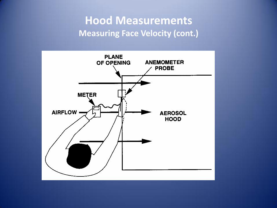
Hood Measurements Measuring Face Velocity (cont.)

Hood Measurements Smoke visualization

Hood Measurements Smoke Generators
Smoke tubes
Theater smoke generator – “DJ Fogger”

Duct Measurements Static Pressure
• What/Where: – Vacuum or Pressure Exerted on the Inside of a Duct and
measured perpendicular to air flow (SP)
– Constant across a cross sectional area of a duct
• Units: – Inches or mm of Water, Pascals
• Instruments: – Slack or U-tube Manometer
– Manometer

Duct Measurements U-tube Liquid Filled Manometer
Primary standard – no calibration needed

Duct Measurements Slack or U-tube Manometer
• Measures: Vacuum or Pressure
• Units: Inches or mm of Water
• Fluids: - Water with Green Coloring - Red Oil
- Mercury

Duct Measurement-
Manometer
Fluid
Comparison

Duct Measurement Measuring Static Pressure

Duct Measurements Magnehelic Gauges
• Measures Pressure or Vacuum (< 15 psig rated)
• Must be routinely calibrated – hard bump can change reading
• Calibrated in mm
WC, in WC, in Hg, PSI

Duct Measurements Velocity Pressure (VP)
• What/Where: – In the linear flow of the airstream – measured parallel to the air
flow (VP) – VP changes across the cross sectional area of a duct (velocity profile) – Air volume can be calculated from VP, Q=VA and V= 4005 (VP/df)0.5
• Units:
– Inches or mm of Water, Pascals
• Instruments: – Pitot tube &
• Inclined Manometer • Slack or U-tube Manometer • Manometer, Magnehelic gage

Duct Measurements Pitot Tube – VP
Remember TP = VP + SP?
VP = TP – SP; V = 4005 (VP/df)0.5

Duct Measurements Inclined Manometer
• Range: – 0-2 inches of
Water
– 0-50 mm of Water
• Uses “0.826 Red Oil”
• Being level is critical!

Duct Measurements Pitot Tube & Inclined Manometer

Duct Measurements Measuring Airflows
• Equipment set-up
• Location of Test Port
– 7 D upstream
– 4 D downstream
• Traverse Pattern
• Recording Data
• Proper Calculations
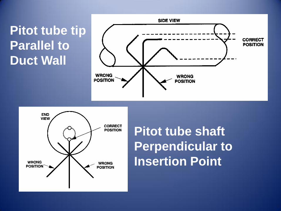
Pitot tube tip
Parallel to
Duct Wall
Pitot tube shaft
Perpendicular to
Insertion Point

Duct Velocity
Profile
Duct Traverse
Points – Equal
Concentric
Areas – Good
Averaging

Equal Area Traverse Points
Traverse Point/
% diameter
2 4 6 8 10
1 14.6 6.7 4.4 3.2 2.6
2 85.4 25.0 14.6 10.5 8.2
3 X 75.0 29.6 19.4 14.6
4 X 93.3 70.4 32.3 22.6
5 X X 85.4 67.7 34.2
6 X X 95.6 80.6 65.8
7 X X X 89.5 77.4
8 X X X 96.8 85.4
9 X X X X 91.8
10 X X X X 97.4

Volumetric Flow Rate – Pitot Tube Traverse
Points VPh Vh VPv Vv
0.19” 0.55 0.57
0.81” 0.79 0.78
1.93” 0.95 0.90
4.07” 0.94 0.91
5.19” 0.81 0.79
5.81” 0.64 0.61
Dry air at 70 F is flowing in a 6” diameter duct at sea level. Calculate Volumetric Flow Rate.

Calculate Air Flow
• Convert Velocity Pressures to Velocity
– V=4005(VP/df) (1/2)
– df = 1 for sea level and 70 F
• For first value:
– V=4005(0.55/1) (1/2) = 2970 ft/min

Volumetric Flow Rate – Pitot Tube Traverse
Points VPh Vh VPv Vv
0.19” 0.55 2970 0.57 3024
0.81” 0.79 3560 0.78 3537
1.93” 0.95 3904 0.90 3799
4.07” 0.94 3883 0.91 3821
5.19” 0.81 3605 0.79 3560
5.81” 0.64 3204 0.61 3128
21126 20869
Dry air at 70 F is flowing in a 6” diameter duct at sea level. Calculate Volumetric Flow Rate.

Complete Calculation
• Average velocity:
– (21126 + 20869)/12 = 3500 ft/min
• Q = V x A
• A 6” duct = pi x 62/4 x (144) = 0.1963 sq.ft.
• Q = 3500 x 0.1963 = 687 ft3/min

Volumetric Flow Rate – Pitot Tube Traverse
Points VPh Vh VPv Vv
0.19” 0.55 0.57
0.81” 0.79 0.78
1.93” 0.95 0.90
4.07” 0.94 0.91
5.19” 0.81 0.79
5.81” 0.64 0.61
The actual air temperature was 150 F. What is the corrected flow rate for the 6” diameter duct at sea level.

Pitot Tube Traverse
• The Pitot Tube and monometer are calibrated at standard air
• Standard Air is dry air at 70 F and 29.92 (ins HG) barameter. The density of air at STP is 0.075 lb/ft³ and the df is 1.0
• Therefore, under non-standard conditions the measured VPs taken with a pitot tube must be corrected by:
V=4005(VP/df) (1/2)
In order to determine Actual Cubic feet per minute
(ACFM)

Pitot Tube Traverse Density Factors
Air Density Correction Factors (df) :

Air with different density
• Convert Velocity Pressures to Velocity
– V=4005(VP/df) (1/2)
– df = 1 for sea level and 70 F
– df = (70+460)/(150+460) = 530/610 = 0.87
• For first value:
– V=4005(0.55/0.87) (1/2) = 3184 versus 2970 ft/min

Volumetric Flow Rate – Pitot Tube Traverse
Points VPh Vh VPv Vv
0.19” 0.55 3184 0.57 3241
0.81” 0.79 3816 0.78 3792
1.93” 0.95 4185 0.90 4073
4.07” 0.94 4163 0.91 4096
5.19” 0.81 3864 0.79 3816
5.81” 0.64 3435 0.61 3354
22648 22372
The actual air temperature was 150 F. What is the corrected flow rate for the 6” diameter duct at sea level. df=0.87

Complete Calculation
• Average velocity:
– (22648 + 22372)/12 = 3752 ft/min
• Q = V x A
• A 6” duct = pi x 62/4 x (1/44) = 0.1963 sq.ft.
• Q = 3752 x 0.1963 = 736 versus 687 ACFM (7% greater volume)

Fan Measurements
• Shaft speed: (check against fan curve)
– hand held tachometer
• Fan motor current: (rough estimate of total airflow)
– Clamp on ammeter

Troubleshooting
If an existing ventilation system appears to not be functioning properly, the following simple checks can be made without extensive measurements or expert
help: • Is the fan belt broken or slipping?
• Is the fan wired backward (reversed polarity)?
• Is ductwork clogged with dust?
• Is there holes, cracks or openings in the ducting?
• Is the air cleaner clogged?
• Are any dampers in the ductwork closed?
• Is there insufficient makeup air?

Troubleshooting
• Has ductwork been changed to include more length, more or sharper bends, or abrupt diameter changes?
• Have additional hoods and ductwork been added? Without proper airflow balancing, some hoods in a multiple system may have inadequate flow. Or the fan may be too small to handle the additional resistance.
• Has the contaminant source been moved further away from the hood opening?

Troubleshooting
• Is more contaminant being generated at the source?
• Are cooling fans causing cross drafts?
• Have employees modified the hood because it interferes with their job tasks?
Many of these problems can be avoided by periodic maintenance and measurements of air velocities or pressures
of ventilation systems.

TESTING AND TROUBLESHOOTING
OF
VENTILATION SYSTEMS
Questions?


