Embed Size (px)
DESCRIPTION
Test Switches & Plugs. Type FT. Type RT. Type PK-2. Agenda. What are Test Switches & Test Plugs? 10 Pole FT Test Switches Features & Uses Design Details Selection & Ordering Information Typical Connection Diagram 10 Pole FT Test Plugs “In-Service Series” Application - PowerPoint PPT Presentation
Citation preview

1
GE Digital EnergyInstrument Transformers, Inc.
Test Switches & Plugs
Type FT
Type RT
Type PK-2

2
GE Digital EnergyInstrument Transformers, Inc.
Agenda What are Test Switches & Test Plugs?
10 Pole FT Test SwitchesFeatures & UsesDesign DetailsSelection & Ordering InformationTypical Connection Diagram
10 Pole FT Test Plugs“In-Service Series” Application“Separate Source” Application
Typical FT Test Switch Installations
RT Rack Mounted Test Switches
ABB to ITI Cross Reference for FT Test Switches
4 & 6 Pole PK-2 Test Blocks and PlugsOrdering InformationFeatures & UsesDesign Details
3
GE Digital EnergyInstrument Transformers, Inc.
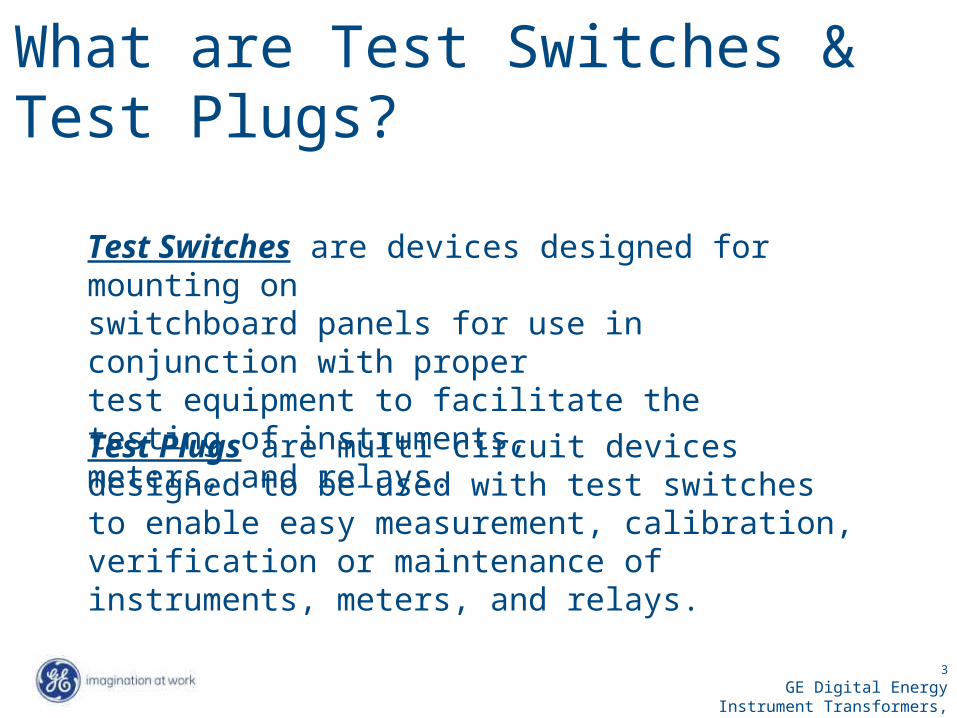
What are Test Switches & Test Plugs?
Test Switches are devices designed for mounting on switchboard panels for use in conjunction with proper test equipment to facilitate the testing of instruments,meters, and relays. Test Plugs are multi circuit devices designed to be used with test switches to enable easy measurement, calibration, verification or maintenance of instruments, meters, and relays.

4
GE Digital EnergyInstrument Transformers, Inc.
FT Test Switches
10 PoleFT Test Switch
10 PoleFT Test Plug
Consist of (2) components

5
GE Digital EnergyInstrument Transformers, Inc.
10 Pole FT Test Switch -- Features & Uses
Semi-flush mounted in front panel
Rear termination provisions
Configurable to meet customer requirements
Black or clear (optional) safety cover
Provisions for meter type seal
Isolate relay inputs & outputs for injection of current & voltage from separate sources(Use “Separate Source” Test Plug)
Measure system currents & voltages during field testing & commissioning (Use “In-Service Series” Test Plug)
FTC-066 Test Switch with clear coverFT-066 Test Switch with black cover
6
GE Digital EnergyInstrument Transformers, Inc.
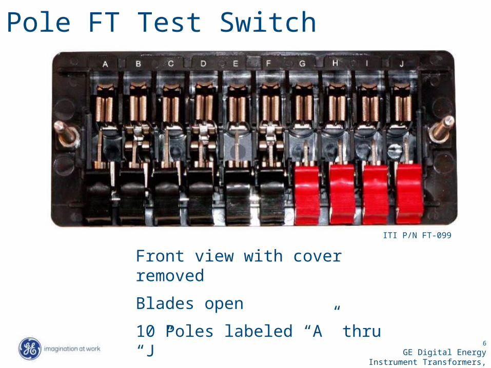
10 Pole FT Test Switch
Front view with cover removed
Blades open
10 Poles labeled “A” thru “J”
ITI P/N FT-099

7
GE Digital EnergyInstrument Transformers, Inc.
FT Test Switch – Rear terminals
Threaded rear terminals
Terminal numbers molded into base
Nickel plated brass pan head screws, flats, & locks supplied loose
Threaded studs and hex nuts available as option

8
GE Digital EnergyInstrument Transformers, Inc.
FT Pole Assemblies
“P” = Potential “C” = CurrentNon-Shorting
“C-C” Current
Shorting (2-Poles Required)
“C-C-C” Current
Shorting (3-Poles Required)
“C-C-C-C” Current
Shorting (4-Poles Required)

9
GE Digital EnergyInstrument Transformers, Inc.
10 Pole FT Test Switch Typical Selection table
(Note poles A through J……Reference slide 4)
“P” = Potential (Poles A, B, & J)
“C” = CurrentNon-Shorting
(Pole C)
“C-C” = Current Shorting (2-Poles
Required)(Poles D-E, F-G, & H-I)
Schematic Symbols

10
GE Digital EnergyInstrument Transformers, Inc.
FT Test Switch Potential Pole “P”
Non-Shorting Blade used for voltage and trip circuits
Blade assembly of (1) position potential pole (P)
Rear Termination Provision
11
GE Digital EnergyInstrument Transformers, Inc.
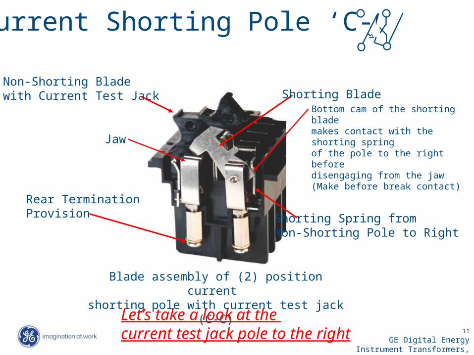
Blade assembly of (2) position current shorting pole with current test jack (C-C)
Shorting BladeBottom cam of the shorting blademakes contact with the shorting springof the pole to the right before disengaging from the jaw (Make before break contact)
Shorting Spring from Non-Shorting Pole to Right
Non-Shorting Bladewith Current Test Jack
Rear Termination Provision
FT Current Shorting Pole ‘C-C’
Jaw
Let’s take a look at the current test jack pole to the right

12
GE Digital EnergyInstrument Transformers, Inc.
FT Non-Shorting Current Pole ‘C’
Blade assembly of non-shorting current pole with current test jack (C) --- Part of 2-pole
(C-C)
Current Test Jackfor insertion of current test probe
Rear Termination Provision
Jaw
Non-Shorting Blade (Open)
13
GE Digital EnergyInstrument Transformers, Inc.
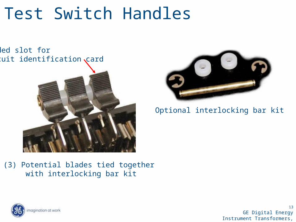
FT Test Switch Handles
Optional interlocking bar kit
(3) Potential blades tied together with interlocking bar kit
Molded slot for circuit identification card

14
GE Digital EnergyInstrument Transformers, Inc.
FT Test Switch Part Number System
See next slide for typical selection chart

15
GE Digital EnergyInstrument Transformers, Inc.
Typical FT Test Switch & Test Plug Selection Chart
Test Switch Part Number FT-066
In-Service Series Test Plug Part Number
Potential Pole Position “A” (2) Pole Current Shorting with Test Jack Position “F-G”

16
GE Digital EnergyInstrument Transformers, Inc.
Non-Standard FT Test Switch Specification FormStep 1The switch body can support 1 to 10 poles in slots marked A through J.
Enter a letter from the legend. Leave unused slots blank.
Legend:P = Potential, Black; T = Potential, Red; O = Potential, Orange; Y = Potential, Yellow; G = Potential, Green;B = Potential, Blue; W = Potential, White C = Current, Non-shorting, BlackR = Current, Non-shorting, RedC--C, C--C--C, C--C--C--C = Current, Shorting with current test jack right most position, BlackR--R, R--R--R, R--R--R--R = Current, Shorting with current test jack right most position, RedCO = Current, Orange; CY = Current, Yellow;CG = Current, Green; CB = Current, Blue; CW = Current, White Note: Some functions will require more than one slot in the switch body
Step 2If a tie bar is required check this boxand draw a dark heavy line over the poles to be joined.In the example above positions H, I, & J will operate together.
Step 3 Select a cover styleClear (Installs over open or closed switches)Black (Installs over closed switches only)
Step 4 Select a rear terminal type
Screws (Standard) Studs (Optional)
A B C D E F G H I J
C C- -C R- -R- -R- -R PP PExample:
A B C D E F G H I J
17
GE Digital EnergyInstrument Transformers, Inc.
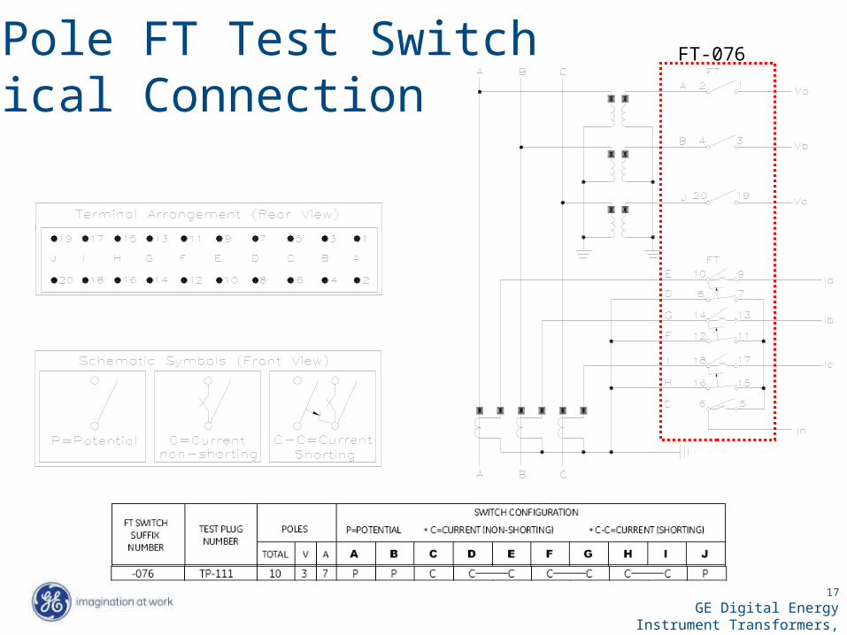
10 Pole FT Test Switch Typical Connection
FT-076
18
GE Digital EnergyInstrument Transformers, Inc.
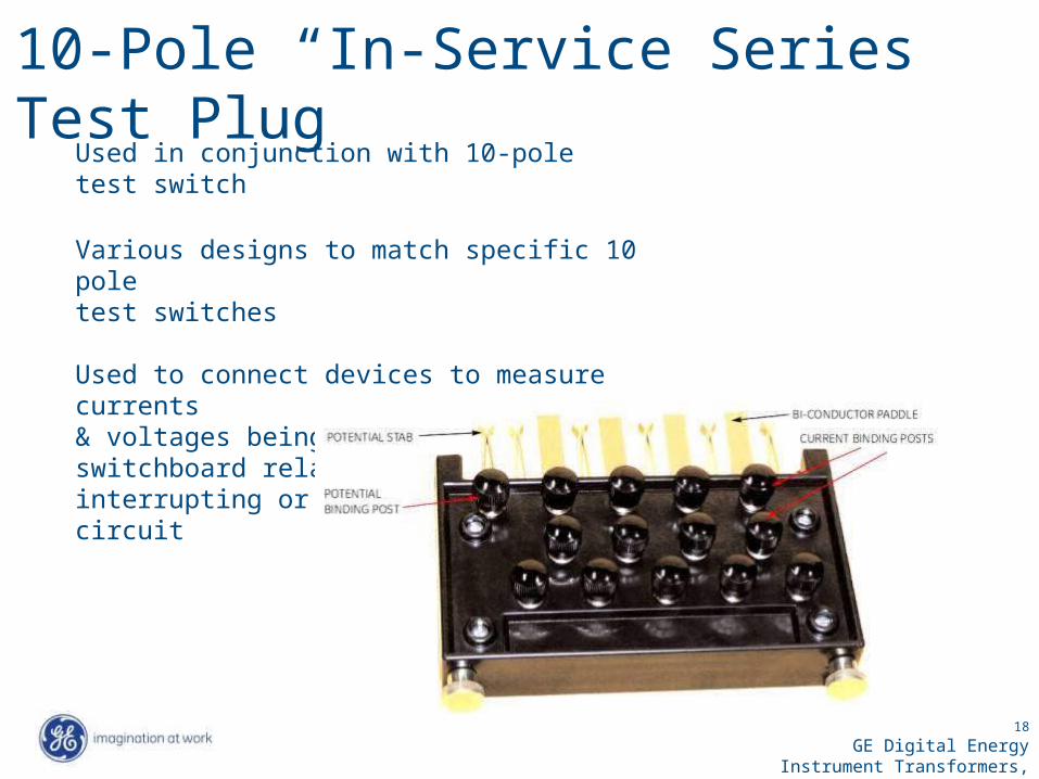
10-Pole “In-Service Series” Test Plug
Used in conjunction with 10-pole test switch
Various designs to match specific 10 pole test switches
Used to connect devices to measure currents & voltages being applied to the switchboard relays & meters without interrupting or short circuiting the circuit
19
GE Digital EnergyInstrument Transformers, Inc.
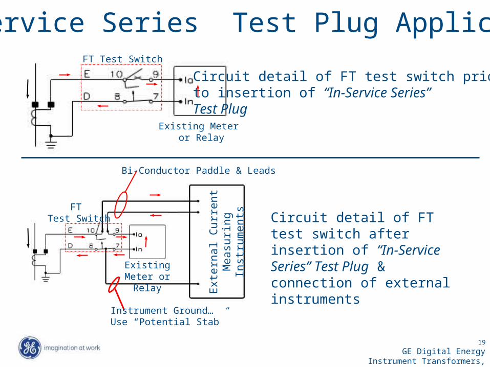
“In-Service Series” Test Plug Application
Circuit detail of FT test switch prior to insertion of “In-Service Series” Test Plug
FT Test Switch
Existing Meter or Relay
Existing Meter or
Relay
Circuit detail of FT test switch after insertion of “In-Service Series” Test Plug & connection of external instrumentsE
xte
rnal C
urr
ent
Measu
ring
Inst
rum
ents
FT Test Switch
Bi-Conductor Paddle & Leads
Instrument Ground…Use “Potential Stab”

20
GE Digital EnergyInstrument Transformers, Inc.
10-Pole “Separate Source” Test Plug
Used in conjunction with 10-pole test switch
Used to isolate and connect the “out of service” relays or switchboard devices to external test instruments
Currently Not Available from ITI
ABB Part Number 1164046States Part Number FTP10-10

21
GE Digital EnergyInstrument Transformers, Inc.
Bi-Conductor Paddle & Leadto External Current Supply
“Separate Source” Test Plug Application
Circuit detail of FT test switch prior to insertion of “Separate Source” Test Plug
FT Test Switch
Existing Meter or Relay
Separ a
te S
our c
e
Cur r
ent
Su
pply
Circuit detail of FT test switch after insertion of “Separate Source” Test Plug & connection of external current supply
Existing Meter or
Relay
FT Test Switch

22
GE Digital EnergyInstrument Transformers, Inc.
MV MCC
MV Switchgear
FT Switches – Typical Installations
Relay / ControlPanels

23
GE Digital EnergyInstrument Transformers, Inc.
Multilin Standard RT Model
Up to (3) type FT Switches per panel
Black panel – 19 inches wide x 5.22” high
Full width clear cover – handles either open or closed
Meter seal provisions
Padlock provisions
Access to panel mounting hardware prevented with cover installed
Clear safety shield at rear screw terminal area
Right FT suffix
Center FT suffix
Left FT suffix
RT LLL CCC RRR
Part number system

24
GE Digital EnergyInstrument Transformers, Inc.
Optional RT Models Available
Up to (3) type FT switches per panel
Panel heights: 3.47”5.22”5.22” offset6.97”
Panel colors:ANSI 61 & 49 grayBrushed aluminum
Full width clear cover –handles either open or closed

25
GE Digital EnergyInstrument Transformers, Inc.
Part number system for optional RT models

26
GE Digital EnergyInstrument Transformers, Inc.
FT Test Switch - ABB to ITI Cross Reference (*)ABB
Part Number
ITI Part Number(FT-____)
ABB Part Number
ITI Part Number(FT-____)
ABB Part Number
ITI Part Number(FT-____)
ABB Part Number
ITI Part Number(FT-____)
ABB Part Number
ITI Part Number(FT-____)
129A501G01 066 129A521G01 054 129A545G01 062 291B956G13 013 498A027G01 012129A502G01 044 129A523G01 028 129A546G01 043 291B956G18 010 629A315G01 052129A503G01 035 129A524G01 009 129A547G01 032 291B956G23 014 629A483G01 061129A504G01 021 129A525G01 053 129A548G01 060 291B959G18 036 837A101G01 130129A505G01 015 129A526G01 033 129A549G01 045 291B959G19 034 837A407G01 085129A506G01 008 129A528G01 075 129A550G01 020 291B960G26 047129A507G01 011 129A529G01 081 129A551G01 059 498A002G01 018129A508G01 017 129A530G01 050 129A553G01 069 498A004G01 057129A509G01 023 129A531G01 004 129A555G01 019 498A008G01 040129A510G01 037 129A532G01 070 188A229G01 056 498A010G01 084129A511G01 041 129A533G01 016 188A261G01 038 498A011G01 067129A512G01 051 129A534G01 002 188A304G01 026 498A013G01 031129A513G01 072 129A535G01 076 188A416G01 022 498A014G01 027129A514G01 074 129A537G01 025 188A454G01 030 498A015G01 073129A515G01 064 129A538G01 007 188A477G01 039 498A016G01 049129A516G01 029 129A539G01 083 188A618G01 042 498A019G01 055129A517G01 058 129A541G01 080 188A632G01 046 498A020G01 082129A518G01 078 129A542G01 068 188A633G01 063 498A021G01 065129A519G01 077 129A543G01 024 291B954G12 005 498A022G01 006129A520G01 071 129A544G01 048 291B954G13 001 498A026G01 003
Consult factory for other part numbers
(*) This cross reference is intended to be accurate; however, all equivalent part numbers are based on available competitor product data only. Therefore this cross reference should be used as a guide only. All recommended ITI configurations to be confirmed by customer before placing orders.

27
GE Digital EnergyInstrument Transformers, Inc.
PK-2 Test Blocks & Plugs
4 & 6 PolePK-2 Test Block
4 & 6 PolePK-2 Test Plug
P/N 6422120G1 4-Pole; surface mount on 1 to 2 inch panels
P/N 6422120G2 6-Pole; surface mount on 1 to 2 inch panels
P/N 6422120G3 4-Pole; semi-flush on 0.12 inch panelssurface mount on 0.12 to 0.5 inch
panels
P/N 6422120G4 6-Pole; semi-flush on 0.12 inch panelssurface mount on 0.12 to 0.5 inch
panels
P/N 6129533G1 4-Pole
P/N 6129533G2 6-Pole

28
GE Digital EnergyInstrument Transformers, Inc.
PK-2 Test Blocks – Features & Uses
Semi-flush or surface mounted
Cover removal automatically shorts current circuits
Rear termination provisions
Provided with unmounted auxiliary contacts, jumpers,and hardware for field installation into test block
Reference application data for typical arrangements of contacts & jumpershttp://www.multilin.com; Type PK-2 in “search”; Select “PK-2 test Blocks and Plugs – Product Information”; Select “Brochures”
Routine testing accomplished by removing coverand inserting the properly connected test plug
Normal connections restored by replacing cover

29
GE Digital EnergyInstrument Transformers, Inc.
PK-2 Test Blocks
Legend:
6-Pole Test Block with Cover Removed(Component parts defined below)
(1) Auxiliary Contact Maintains circuit with cover or plug not installed
(2) Auxiliary Contact Short circuits CT with cover or plug not installed
(3) Jumper Used with contacts (2) or (4) -- short circuits CT or interconnects phases when cover-fastening stud is to
be bypassed
(4) Auxiliary Contact Equal to one pole of contact (2) & used with jumper (3)
2
1
3
4

30
GE Digital EnergyInstrument Transformers, Inc.
PK-2 Test Plugs
Test Links supplied with plug(4) with the 4-pole(6) With the 6-pole
Links can be installed vertically or horizontally
Refer to application data for typical test link arrangements http://www.multilin.com; Type PK-2 in “search”; Select “PK-2 test Blocks and Plugs – Product Information”; Select “Brochures”
Test Links

31
GE Digital EnergyInstrument Transformers, Inc.
QUESTIONS