Embed Size (px)
Citation preview

TRF No. IEC 62509_V1.0
Page 1 of 55
Test Report issued under the responsibility of:
TEST REPORT IEC 62509
Battery charge controllers for photovoltaic systems – Performance and functioning
Report:
Report Reference No…................... : 6046293.50
Tested by (name + signature) ......... : Jason Guo
Approved by (name + signature) ..... : Allan Chen
Date of issue................................... : 2019-01-14
Total number of pages ……………...: 55 pages
Testing Laboratory ....................... : DEKRA Testing and Certification (Shanghai) Ltd.
Address .......................................... : 3F #250, Jiangchangsan Road Building 16, Headquarter Economy Park Shibei Hi-Tech Park, Zhabei District, Shanghai 200436, China
Applicant’s name .......................... : SRNE Solar Co., Ltd
Address .......................................... : 4-5F,13A Wutong Island, Neihuan Rd, Xixiang, Bao’an, Shenzhen, Guangdong, China
Test specification:
Standard ......................................... : IEC 62509:2010 (Edition 1.0)
Test procedure ............................... : Type test
Non-standard test method ............... : N/A
Test Report Form No. ................... : IEC 62509_V1.0
TRF Originator ................................ : DEKRA Testing and Certification (Shanghai) Ltd.
Master TRF .................................... : 2016-03
Test item description .................... : Solar Charge Controller
Trade Mark ..................................... :
Manufacturer .................................. : SRNE Solar Co., Ltd
4-5F,13A Wutong Island, Neihuan Rd, Xixiang, Bao’an, Shenzhen, Guangdong, China
Model/Type reference ..................... : ML2420, ML2430, ML2440, ML4830

Page 2 of 55 Report No. 6046293.50
TRF No. IEC 62509_V1.0
Rating ............................................. : ML2420:
Max PV input: 100 Vdc (25°C), 90 Vdc (-25°C), 260 W / 12Vdc, 520 W / 24Vdc;
Battery: 12 / 24 Vdc, max charging current: 20 A;
Load output: 12 / 24 Vdc, 20 A max
ML2430:
Max PV input: 100 Vdc (25°C), 90 Vdc (-25°C), 400 W / 12Vdc, 800 W / 24Vdc;
Battery: 12 / 24 Vdc, max charging current: 30 A;
Load output: 12 / 24 Vdc, 20 A max
ML2440:
Max PV input: 100 Vdc (25°C), 90 Vdc (-25°C), 550 W / 12Vdc, 1100 W / 24Vdc;
Battery: 12 / 24 Vdc, max charging current: 40 A;
Load output: 12 / 24 Vdc, 20 A max
ML4830:
Max PV input: 150 Vdc, 400 W / 12Vdc, 800 W / 24Vdc, 1200 W / 36Vdc, 1600 W / 48Vdc;
Battery: 12 / 24 / 36 / 48 Vdc, max charging current: 30 A;
Load output: 12 / 24 / 36 / 48 Vdc, 20 A max

Page 3 of 55 Report No. 6046293.50
TRF No. IEC 62509_V1.0
Test item particulars............................................... :
Equipment mobility .................................................. : movable hand-held stationary fixed transportable for building-in
Connection to the mains .......................................... : pluggable equipment direct plug-in permanent connection for building-in Not connected to mains
Enviromental category ............................................. : outdoor indoor indoor unconditional conditional
Over voltage category Mains .................................... : OVC I OVC II OVC III OVC IV Not connected to mains
Over voltage category PV ........................................ : OVC I OVC II OVC III OVC IV
Over voltage category Battery .................................. : OVC I OVC II OVC III OVC IV
Mains supply tolerance (%) ...................................... : --
Tested for power systems ........................................ : --
IT testing, phase-phase voltage (V) .......................... : --
Class of equipment ................................................. : Class I Class II Class III Not classified
Mass of equipment (kg)............................................ : 1.4 kg for ML2420; 2.0 kg for ML2430, ML2440;
2.3 kg for ML4830
Pollution degree ....................................................... : PD2
IP protection class .................................................... : IP32
Possible test case verdicts:
- test case does not apply to the test object : N/A
- test object does meet the requirement ..................... : P(Pass)
- test object does not meet the requirement ............... : F(Fail)
Testing .................................................................... :
Date of receipt of test item ........................................ : 2018-11-29
Date (s) of performance of tests ................................ : 2018-11-29 to 2018-12-21
General remarks:
The test results presented in this report relate only to the object tested.
This report shall not be reproduced, except in full, without the written approval of the Issuing testing
laboratory.
"(see Appendix #)" refers to additional information appended to the report.
Throughout this report a point is used as the decimal separator.
The test results presented in this report relate only to the item tested.
This report is not used for social proof function in China market
The measurement result is considered in conformance with the requirement if it is within the prescribed limit, It
is not necessary to account the uncertainty associated with the measurement result.
Name and address of factory (ies):
SRNE Solar Co., Ltd
4F, Xinju Road No.10, Shangjiao Village, Chang’an Town, Dongguan City, Guangdong, China

Page 4 of 55 Report No. 6046293.50
TRF No. IEC 62509_V1.0
General product information:
This solar charge controller can keep monitoring the solar panel's generating power and tracking the highest voltage and current values (V-I) in real time, enabling the system to charge the battery in maximum power. It's designed to be used in off-grid solar photovoltaic systems to coordinate operation of the solar panel, battery and load, functioning as the core control unit in off-grid photovoltaic systems. This solar charge controller have below protection function: - Input power limiting protection - Battery reverse connection protection - Photovoltaic input side too high voltage protection - Photovoltaic input side short-circuit protection - Photovoltaic input reverse-connection protection - Load overpower protection - Load short-circuit protection - Reverse charging protection at night - TVS lighting protection - Over-temperature protection. The operation temperature range is specified as: - 35°C to 45°C. The product was tested on: ML2420 Hardware Version: V0.3 Software Version: V1.3.5 ML2430 Hardware Version: V0.5 Software Version: V1.3.0 ML2440 Hardware Version: V0.5 Software Version: V1.4.8 ML4830 Hardware Version: V0.7.1 Software Version: V2.0.1

Page 5 of 55 Report No. 6046293.50
TRF No. IEC 62509_V1.0
Copy of marking plate:

Page 6 of 55 Report No. 6046293.50
IEC 62509
Clause Requirement - Test Result - Remark Verdict
TRF No. IEC 62509_V1.0
4 Functionality and performance requirements of a PV BCC P
4.1 General P
This Clause describes the performance and functionality requirements for PV battery charge controllers (BCC). These requirements are divided in 5 main categories:
P
Battery lifetime protection. Considered. P
Efficiency. Considered. P
User interface. Considered. P
Fail safe functions. Considered. P
Marking and documentation. Considered. P
The provisions in this standard are not intended to preclude or rule out innovative control techniques aimed at providing effective battery charging. These however shall be verifiable by testing.
P
4.2 Applicability of requirements P
Required provisions ensure reliable operation and essential protection functions, and are generally easily achievable on even inexpensive BCCs intended for small installations (e.g. single module installations at extra low voltage).
P
Recommended provisions ensure more effective battery charging, better efficiencies, longer battery lifetime and additional user interface functions. They are intended to provide and/or facilitate more advanced battery charging and load management.
P
4.3 Battery lifetime protection requirements P
4.3.1 Prevent leakage current from battery to PV generator
See appended table. P
The BCC shall limit leakage current flowing from the battery to the PV generator in order to prevent battery discharging at night. The allowable reverse current on the PV side shall be ≤ 0,1 % of the BCC rated input current when the battery voltage is equal to the rated voltage.
P
Compliance shall be verified by test according to 5.2.1.
P
4.3.2 Basic battery charging functions P
4.3.2.1 General P
The BCC shall provide appropriate charging set-points and load disconnect set-points for the specific battery technology or technologies it is intended to be used for.
P

Page 7 of 55 Report No. 6046293.50
IEC 62509
Clause Requirement - Test Result - Remark Verdict
TRF No. IEC 62509_V1.0
4.3.2.2 Protect battery from over-charge P
The BCC shall cut out or regulate the charging current to avoid over-charging of the battery according to battery manufacturer recommended end of charge set point.
Considered. P
Compliance shall be determined by test according to 5.2.2.
P
4.3.2.3 Protect battery from over-discharge P
The BCC shall have a provision to prevent the battery from over-discharging either by directly interrupting the current to the load, or by a trip signal to enable an external piece of equipment to stop the current to the load, or an alarm.
Considered. P
If battery over-discharge protection is achieved by means of audible or visible alarms that prompt the system user to disconnect all or non-essential load, this shall be clearly stated in the operation manual.
P
If over-discharge protection is reliant on the installation of an external device that provides over-discharge protection (such as an inverter), this fact shall be clearly stated in the installation manual.
Not rely on the installation of an external device.
N/A
Battery over-discharge protection can be triggered by a battery voltage measurement, a state of charge calculation, a combination of both or other algorithms. The protection set-points may be current compensated. Battery over-discharge protection set-point shall be verifiable by testing. The BCC documentation and/or interface shall clearly specify the algorithms and criteria used to establish the load disconnect and reconnect set-points.
P
Compliance shall be determined by test according to 5.2.3.
P
4.3.2.4 Set-point accuracy P
The BCC measurement accuracy for voltage
set-points for charge control shall be ±1 % or
better. For load disconnect it shall be ±2 % or
better.
Considered. P
Compliance shall be determined by test according to 5.2.2 and 5.2.3.
P
4.3.3 Charging regime P
4.3.3.1 General P

Page 8 of 55 Report No. 6046293.50
IEC 62509
Clause Requirement - Test Result - Remark Verdict
TRF No. IEC 62509_V1.0
The BCC shall be matched to the specific battery technology for its intended use to ensure that correct charging set-points are implemented. The PV BCC can use a variety of methods to ensure correct charging of batteries, the requirements in this clause include some of the possible solutions and do not limit other solutions.
P
4.3.3.2 Required charging stages P
As a minimum, PV battery charge controllers shall have bulk and float charging stages.
Considered. P
4.3.3.3 Recommended charging stages P
In addition to the requirements of 4.3.3.2, battery charge controllers should provide equalize charge periodically to the battery. The periodicity of equalise charge should be more than 7 days.
Considered. P
4.3.3.4 Adjustable charging set-points P
Self-adaptive set-points based on advanced algorithms shall be able to be verified using information provided by the user interface and the BCC documentation. No specific test procedure has been developed for devices employing these advanced techniques.
Automatic recognition of battery voltage is supported.
P
4.3.3.5 Temperature compensated charging set-points P
Bulk, float, and other high voltage or end of charge set-points should be temperature compensated. Temperature compensation if provided should be in accordance with battery manufacturer recommendations for the particular type of battery. Temperature compensated set-points shall be identifiable from the charge controller documentation.
Considered. P
4.3.3.6 Voltage drop compensation for set-point measurement
P
The BCC should provide a means to compensate for voltage drop in battery cables, or provide installation instructions to minimise voltage drop.
Provide installation instructions to minimise voltage drop.
P
If the battery charge controller has the provision for battery sense cables, it shall be able to operate with or without these. This is to protect the unit against unintended disconnection of the battery sense cables. This requirement is tested according to 5.2.2 and 5.2.3 by performing the test with and without the sense wires connected at 25 °C test conditions.
N/A
4.3.4 Set-point security P

Page 9 of 55 Report No. 6046293.50
IEC 62509
Clause Requirement - Test Result - Remark Verdict
TRF No. IEC 62509_V1.0
Charging set-points shall be secured against change other than by a deliberate and qualified action.
P
Compliance shall be determined by inspection of the unit and accompanying operating instructions.
P
4.3.5 Load disconnect capability P
Where over-discharge protection is provided by means of load disconnect functionality the load disconnect and reconnect set-points shall be verified by testing according 5.2.3.
Disconnect set-point: 11.1 V, reconnect set-point: 12.6 V for each 12 V battery voltage.
P
The load could be either a load directly switched or a load controlled by the BCC by other means. In the case of a BCC directly switching the load this should be provided by means of an integrated load breaking switching device.
P
If a BCC has multiple load disconnect set-points, these shall be verifiable by testing and able to be determined from the BCC user interface and/or clearly written in documentation.
N/A
4.4 Energy performance requirements P
4.4.1 Stand by self-consumption P
With no PV input or load the self-consumption of a PV BCC shall be as detailed in Table 1, when the
battery voltage is equivalent to 2,1 V/Cell ± 2 %,
and the ambient temperature is 25 °C±2 °C.
See appended table. P
Compliance shall be determined by test according to 5.3.1.
P
4.4.2 BCC efficiency P
Power efficiency of the BCC shall be evaluated from 10 % to 100 % of the rated charging current,
at a battery voltage equivalent to 2,2 V/Cell±2 %
and at ambient temperature of 25 °C±2 °C.
See appended table. P
The efficiency shall be determined by test according to 5.3.2
P
4.5 Protection and fail safe requirements P
4.5.1 Thermal performance P

Page 10 of 55 Report No. 6046293.50
IEC 62509
Clause Requirement - Test Result - Remark Verdict
TRF No. IEC 62509_V1.0
The BCC shall be capable of handling rated input current/power from the generator and, simultaneously, rated load current to load terminals (if provided) for at least 1 h at the manufacturer’s specified maximum rated ambient operating
temperature±2 °C. Battery voltage shall be 2,2
V/Cell±2 %.
Considered. P
Compliance shall be determined by test according to 5.4.1.
P
4.5.2 Overcurrent operation P
4.5.2.1 PV side P
The BCC shall not be damaged by excessive current from the PV generator up to 125 % of the full rated current. The BCC shall continue to operate normally after such an event and shall not require manual resetting.
See appended table. P
Compliance shall be determined by test according to 5.4.2.
P
4.5.2.2 Load side P
If the BCC has a load terminal, this terminal shall be current protected to prevent over loads from causing damage to the operation of the essential PV BCC functions.
Considered. P
The rating of the load terminals should match the requirement of the intended application/s.
P
4.5.3 PV generator and battery reverse polarity P
The BCC shall be protected from reverse polarity connection of the PV generator or the battery by hardware or by documented procedure and markings.
P
4.5.4 Open circuit on battery terminals (no battery connection)
P
BCC with load terminals shall be protected from damage to itself and protect the load from the open circuit voltage of the PV generator in the case of battery disconnection.
Considered. P
4.6 User interface requirements P
4.6.1 General P
The user interface of a BCC should include any of the following types; LCD screen, LED indicators, audible alarms, relay contacts, other computer interface or other analogue or digital interface. The interface can provide the user with valuable information about the system operation if implemented properly.
LCD screen provided. P

Page 11 of 55 Report No. 6046293.50
IEC 62509
Clause Requirement - Test Result - Remark Verdict
TRF No. IEC 62509_V1.0
The user interface may be integrated into another system component separate from the BCC such as an additional control/logging/interface unit that can be physically connected to the BCC or operate via wireless communication.
P
4.6.2 Operational information P
4.6.2.1 General P
The level of information provided to the user is determined by the intended application and its specific requirements.
P
The user interface of the charge controller should provide information such as detailed in 4.6.2.2.
P
4.6.2.2 Recommended operation information Considered. P
An indication of charging status (i.e. charging or not charging).
P
An indication of load-disconnect state (or over discharge protection status).
P
An indication of the state-of-charge of the connected battery.
P
Other additional operational information displayed by the unit may include but is not limited to:
Considered. P
Charging set-points. P
Battery voltage. P
Charging current. P
Energy input/output. Input/output power provided. N/A
4.6.3 User adjustable set-points and parameters N/A
If user-adjustable set-points or parameters are provided, the user interface shall provide a facility to modify and display those adjustments as specified in 4.3.3.4.
No user-adjustable set-points or parameters are provided.
N/A
Compliance shall be determined by inspection of the unit and accompanying user/installation manual.
N/A
4.6.4 Alarms P
The following conditions should be signalled by the user interface:
P
Low battery state of charge / Low battery voltage / Low availability.
P
Load disconnect. P
BCC trip (e.g. by over temperature). P

Page 12 of 55 Report No. 6046293.50
IEC 62509
Clause Requirement - Test Result - Remark Verdict
TRF No. IEC 62509_V1.0
Visible and/or audible alarms, clearly identifiable by the system user, shall be triggered within the unit in case of any of the above conditions occurring. Audible alarms shall be time limited and revert to a visible alarm or be pulsed.
LED fault indicators and LCD screen which can display abnormal information help users to identify system faults.
P
Compliance shall be determined by test according to 5.2.2 and 5.2.3.
P
5 Tests P
5.1 General conditions for tests P
5.1.1 Setup and preconditioning for tests P
The BCC shall be mounted and installed according to the instructions supplied with the unit. Where the BCC is intended to be installed in a particular manner or configuration (e.g. wallmounting), the installation shall mimic such conditions.
P
The BCC shall be installed in a temperature-controlled chamber for all tests. The test procedure shall not commence until the chamber and BCC temperatures have reached thermal stability.
P
5.1.2 DC power sources for testing P
5.1.2.1 PV input P
The power source used as the PV input should be a PV generator simulator, however, a voltage and current controlled power source in combination with a series resistor (RS in the test diagrams) can be used.
PV simulator used. P
5.1.2.2 Battery simulator P
5.1.3 General test setup P
The general test setup shall be as specified in Figure 1. Any variations or modifications to the basic setup for a particular test are specified in 5.1.4, 5.1.5 and 5.1.6 and in the corresponding test clauses.
P

Page 13 of 55 Report No. 6046293.50
IEC 62509
Clause Requirement - Test Result - Remark Verdict
TRF No. IEC 62509_V1.0
Voltage measurements shall be made at the BCC terminals.
P
5.1.4 Reverse current test setup P
The test setup shall be as specified in Figure 2. P
5.1.5 Charging cycle test setup P
5.1.5.1 General P
The test setup shall be as specified in Figure 1, with the considerations described below.
P
5.1.5.2 PV input P
A PV generator simulator is the preferred option. If a PV generator simulator of the required voltage and/or current ratings is not available, use a power supply with a series resistor (RS).
P
5.1.5.3 Battery simulator P
The battery side PSU is required as a back up for those BCCs that scan the PV IV curve and therefore disconnect the PV current for a few seconds to perform this operation. It is intended to prevent the battery voltage from dipping too much during such IV curve scans.
P
5.1.6 Efficiency, thermal performance and PV overcurrent test setup
P
5.1.6.1 General P
The test setup shall be as specified in Figure 1, with the considerations described in 5.1.5.2 and 5.1.6.2.
P
5.1.6.2 Battery simulator P
5.2 Battery lifetime protection tests P
5.2.1 Battery to PV generator leakage current test See appended table. P
5.2.1.1 Objective/scope P
This test is intended to measure the reverse current through the BCC from the battery to the PV generator, when the PV generator is connected but not producing any current. The test verifies compliance with the requirements of 4.3.1.
Measurements are to be made at 25 °C±2 °C.
P
5.2.1.2 Test setup P
5.2.1.3 Test procedure P
Connect test setup as specified in Figure 2. P
Ensure the conditions specified in 5.1.1 are met.
P
Adjust the battery voltage to 2,1 V/Cell±2 %. P

Page 14 of 55 Report No. 6046293.50
IEC 62509
Clause Requirement - Test Result - Remark Verdict
TRF No. IEC 62509_V1.0
Measure the current in the RPV loop. P
Compare result to requirement of 4.3.1. P
5.2.2 Charging cycle tests See appended table. P
5.2.2.1 Objective/scope P
These tests are intended to measure the charging set-points of the BCC at 25 °C and 40 °C. Measurement at both temperatures allows for verification of set-point temperature compensation when the BCC has this capability.
P
5.2.2.2 Test setup P
As specified in 5.1.5. P
5.2.2.3 Test procedure P
5.2.3 Load disconnect / load reconnect test P
5.2.3.1 Objective/scope P
This test is intended to verify the low voltage set-points used for load disconnect (LVD) and load reconnect (LVR). Measurements are required at 25 °C.
P
5.2.3.2 Test setup P
As specified in 5.1.3. P
5.2.3.3 Test procedure P
5.3 Energy performance tests P
5.3.1 Standby self-consumption test See appended table. P
5.3.1.1 Objective/scope P
The aim of this test is to determine the self-consumption of the battery charge controller in standby mode (no PV input or load).
P
5.3.1.2 Test setup P
As specified in 5.1.3. P
5.3.1.3 Test procedure P
5.3.2 Efficiency test See appended table. P
5.3.2.1 Objective/scope P
The aim of this test is to determine the efficiency curves of the battery charge controller over the range 10 % to 100 % charging current at an ambient temperature of 25 °C.
P
5.3.2.2 Test setup P
As specified in 5.1.6. P
5.3.2.3 Test procedure P

Page 15 of 55 Report No. 6046293.50
IEC 62509
Clause Requirement - Test Result - Remark Verdict
TRF No. IEC 62509_V1.0
5.4 Protection and fail safe tests P
5.4.1 Thermal performance test See appended table. P
5.4.1.1 Objective/scope P
This test is carried out to evaluate the performance of the charge controller at the maximum rated temperature and rated charging current in bulk mode. Where no manufacturer’s maximum rated ambient operating condition is specified then this
test is to be done at 40 C. The effect of a load connected via integrated load switching device should be included in this test.
P
5.4.1.2 Test setup P
As specified in 5.1.6. P
5.4.1.3 Test procedure P
5.4.2 PV overcurrent protection test See appended table. P
5.4.2.1 Test setup P
As specified in 5.1.6. P
5.4.2.2 Objective/scope P
This test is carried out to evaluate the performance of the charge controller under over load conditions
at 25 C and 125 % of the rated charging current in bulk mode.
P
5.4.2.3 Test procedure P
5.4.3 Load over current protection test See appended table. P
5.4.3.1 Objective/scope P
This test is carried out to evaluate the performance of the charge controller at 25 °C and 125 % of the rated load current.
P
5.4.3.2 Test setup P
As specified in 5.1.3. P
5.4.3.3 Test procedure P
5.4.4 Battery reverse polarity test See appended table. P
5.4.4.1 Objective/scope P
This test is intended to verify the BCC tolerance to the connection of the battery in reverse polarity and also to verify the protection of the load from being supplied with negative voltage.
P
5.4.4.2 Test Setup P
As specified in 5.1.3, with the observations specified in the test procedure.
P
5.4.4.3 Test procedure P

Page 16 of 55 Report No. 6046293.50
IEC 62509
Clause Requirement - Test Result - Remark Verdict
TRF No. IEC 62509_V1.0
Review the BCC documentation and the unit itself to verify whether it is capable of withstanding a reverse polarity connection on the battery terminals, or if there is a specific warning not to do so. If a warning is given in the unit or its documentation do not go ahead with the test.
P
5.4.5 PV generator reverse polarity test See appended table. P
5.4.5.1 Objective/scope P
This test is intended to verify the BCC tolerance to the connection of the PV generator in reverse polarity and also to verify the protection of the load from being supplied with negative voltage.
P
5.4.5.2 Test setup P
As specified in 5.1.3 with the observations specified in the test procedure.
P
5.4.5.3 Test procedure P
Revise the BCC documentation and the unit itself to verify whether it is capable of withstanding a reverse polarity connection on PV terminals, or if there is a specific warning not to do so. If a warning is given in the unit or its documentation do not go ahead with the test.
P
5.4.6 Battery open circuit test P
5.4.6.1 Objective/scope P
This test is intended to verify the BCC tolerance to the occurrence of an open circuit on the battery terminals, and the protection of the load from being connected directly to the PV generator voltage.
P
5.4.6.2 Test setup P
As specified in 5.1.6 with the modifications indicated in the test procedure.
P
5.4.6.3 Test procedure After test the BCC can reconnect the battery and is operating normally.
P
5.5 User interface tests Considered. P
User interface requirements are verified mainly by inspection of the BCC and the accompanying instruction and installation manuals. Alarms are verified during other tests such as:
P
Load disconnect / load reconnect test (5.2.3) P
Reverse polarity tests (5.4.4 and 5.4.5) P
Thermal performance test (5.4.1) P
Overcurrent protection test (5.4.2 and 5.4.3) P

Page 17 of 55 Report No. 6046293.50
TRF No. IEC 62509_V1.0
5.2.1 TABLE: Battery to PV generator leakage current test P
Model ML2420
Parameter Test condition Measured value Limits
ILeakage 24 V battery system <1 mA 20 mA (≤ 0,1 %*Irated)
ILeakage 12 V battery system <1 mA 20 mA (≤ 0,1 %*Irated)
5.2.1 TABLE: Battery to PV generator leakage current test P
Model ML2430
Parameter Test condition Measured value Limits
ILeakage 24 V battery system <1 mA 30 mA (≤ 0,1 %*Irated)
ILeakage 12 V battery system <1 mA 30 mA (≤ 0,1 %*Irated)
5.2.1 TABLE: Battery to PV generator leakage current test P
Model ML2440
Parameter Test condition Measured value Limits
ILeakage 24 V battery system <1 mA 40 mA (≤ 0,1 %*Irated)
ILeakage 12 V battery system <1 mA 40 mA (≤ 0,1 %*Irated)
5.2.1 TABLE: Battery to PV generator leakage current test P
Model ML4830
Parameter Test condition Measured value Limits
ILeakage 48 V battery system <1 mA 30 mA (≤ 0,1 %*Irated)
ILeakage 36 V battery system <1 mA 30 mA (≤ 0,1 %*Irated)
ILeakage 24 V battery system <1 mA 30 mA (≤ 0,1 %*Irated)
ILeakage 12 V battery system <1 mA 30 mA (≤ 0,1 %*Irated)
Supplementary information:
The BCC shall limit leakage current flowing from the battery to the PV generator in order to prevent battery discharging at night. The allowable reverse current on the PV side shall be ≤ 0,1 % of the BCC rated input current when the battery voltage is equal to the rated voltage.

Page 18 of 55 Report No. 6046293.50
TRF No. IEC 62509_V1.0
5.2.2 TABLE: Charging cycle test P
Model ML2420
Chamber temperature 25°C
Battery voltage:2.1V/Cell±2% 12.6V
Charging stages Input
voltage (V)
Input current
(A)
Output voltage
(V)
Output current
(A)
Set-point Voltage
(V)
Measured Voltage
(V)
Accuracy (%)
Bulk charge 27.822 10.193 13.11 20.04 N/A N/A N/A
End of bulk charge
29.299 0.075 14.438 0.085 14.4 14.438 0.26
Float charge 30.106 0.069 13.87 0.081 13.8 13.87 0.51
Chamber temperature 40°C
Battery voltage:2.1V/Cell±2% 12.6V
Bulk charge 24.723 12.429 13.129 21.57 N/A N/A N/A
End of bulk charge
24.989 0.083 14.162 0.079 14.13 14.162 0.23
Float charge 24.878 0.075 13.56 0.077 13.53 13.56 0.22
Temperature compensation Set value Measured Value
-3mV/°C / 2V -3.07mV/°C / 2V
Chamber temperature 25°C
Battery voltage:2.1V/Cell±2% 25.2V
Charging stages Input
voltage (V)
Input current
(A)
Output voltage
(V)
Output current
(A)
Set-point Voltage
(V)
Measured Voltage
(V)
Accuracy (%)
Bulk charge 42.781 12.990 25.929 20.487 N/A N/A N/A
End of bulk charge
44.304 0.0827 28.831 0.0899 28.8 28.831 0.11
Float charge 44.705 0.0786 27.57 0.0787 27.6 27.57 0.11
Chamber temperature 40°C
Battery voltage:2.1V/Cell±2% 25.2V
Bulk charge 39.670 14.928 26.129 21.639 N/A N/A N/A
End of bulk charge
39.991 0.091 28.294 0.088 28.26 28.294 0.12
Float charge 39.898 0.087 26.93 0.076 27.06 26.93 0.48
Temperature compensation Set value Measured Value
-3mV/°C / 2V -2.98mV/°C / 2V
Supplementary information:
The temperature compensation function provided, the controller can automatically adjust charging set-point parameters according to temperature change.
The BCC measurement accuracy for voltage set-points for charge control shall be ±1 % or better.

Page 19 of 55 Report No. 6046293.50
TRF No. IEC 62509_V1.0
5.2.2 TABLE: Charging cycle test P
Model ML2430
Chamber temperature 25°C
Battery voltage:2.1V/Cell±2% 12.6V
Charging stages Input
voltage (V)
Input current
(A)
Output voltage
(V)
Output current
(A)
Set-point Voltage
(V)
Measured Voltage
(V)
Accuracy (%)
Bulk charge 28.333 14.359 13.359 28.376 N/A N/A N/A
End of bulk charge
29.298 0.0826 14.328 0.0865 14.4 14.328 0.50
Float charge 29.385 0.0798 13.732 0.0803 13.8 13.732 0.49
Chamber temperature 40°C
Battery voltage:2.1V/Cell±2% 12.6V
Bulk charge 24.633 16.604 13.331 28.52 N/A N/A N/A
End of bulk charge
24.986 0.097 14.063 0 14.13 14.063 0.47
Float charge 24.989 0.078 13.474 0 13.53 13.474 0.41
Temperature compensation Set value Measured Value
-3mV/°C / 2V -2.94mV/°C / 2V
Chamber temperature 25°C
Battery voltage:2.1V/Cell±2% 25.2V
Charging stages Input
voltage (V)
Input current
(A)
Output voltage
(V)
Output current
(A)
Set-point Voltage
(V)
Measured Voltage
(V)
Accuracy (%)
Bulk charge 43.148 18.011 26.132 28.559 N/A N/A N/A
End of bulk charge
44.297 0.0867 28.675 0.0899 28.8 28.675 0.43
Float charge 44.538 0.0795 27.486 0.0856 27.6 27.486 0.41
Chamber temperature 40°C
Battery voltage:2.1V/Cell±2% 25.2V
Bulk charge 44.615 17.585 26.328 28.593 N/A N/A N/A
End of bulk charge
44.992 0 28.118 0 28.26 28.118 0.50
Float charge 44.895 0 26.932 0 27.06 26.932 0.47
Temperature compensation Set value Measured Value
-3mV/°C / 2V -3.09mV/°C / 2V
Supplementary information:
The temperature compensation function provided, the controller can automatically adjust charging set-point parameters according to temperature change.
The BCC measurement accuracy for voltage set-points for charge control shall be ±1 % or better.

Page 20 of 55 Report No. 6046293.50
TRF No. IEC 62509_V1.0
5.2.2 TABLE: Charging cycle test P
Model ML2440
Chamber temperature 25°C
Battery voltage:2.1V/Cell±2% 12.6V
Charging stages Input
voltage (V)
Input current
(A)
Output voltage
(V)
Output current
(A)
Set-point Voltage
(V)
Measured Voltage
(V)
Accuracy (%)
Bulk charge 28.015 21.174 13.829 39.585 N/A N/A N/A
End of bulk charge
29.298 0 14.4 0 14.4 14.4 0
Float charge 29.586 0 13.72 0 13.8 13.72 0.58
Chamber temperature 40°C
Battery voltage:2.1V/Cell±2% 12.6V
Bulk charge 24.476 24.016 13.652 39.64 N/A N/A N/A
End of bulk charge
24.987 0 14.13 0 14.13 14.13 0
Float charge 24.985 0 13.58 0 13.53 13.58 0.37
Temperature compensation Set value Measured Value
-3mV/°C / 2V -3.0mV/°C / 2V
Chamber temperature 25°C
Battery voltage:2.1V/Cell±2% 25.2V
Charging stages Input
voltage (V)
Input current
(A)
Output voltage
(V)
Output current
(A)
Set-point Voltage
(V)
Measured Voltage
(V)
Accuracy (%)
Bulk charge 58.121 19.06 26.933 39.378 N/A N/A N/A
End of bulk charge
59.313 0 28.779 0 28.8 28.779 0.003
Float charge 59.417 0 27.63 0 27.6 27.63 0.11
Chamber temperature 40°C
Battery voltage:2.1V/Cell±2% 25.2V
Bulk charge 44.457 24.941 26.655 39.783 N/A N/A N/A
End of bulk charge
44.993 0 28.228 0 28.26 28.228 0.11
Float charge 44.896 0 27.12 0 27.06 27.12 0.22
Temperature compensation Set value Measured Value
-3mV/°C / 2V -3.06mV/°C / 2V
Supplementary information:
The temperature compensation function provided, the controller can automatically adjust charging set-point parameters according to temperature change.
The BCC measurement accuracy for voltage set-points for charge control shall be ±1 % or better.

Page 21 of 55 Report No. 6046293.50
TRF No. IEC 62509_V1.0
5.2.2 TABLE: Charging cycle test P
Model ML4830
Chamber temperature 25°C
Battery voltage:2.1V/Cell±2% 12.6V
Charging stages Input
voltage (V)
Input current
(A)
Output voltage
(V)
Output current
(A)
Set-point Voltage
(V)
Measured Voltage
(V)
Accuracy (%)
Bulk charge 38.482 11.452 13.558 30.33 N/A N/A N/A
End of bulk charge 39.355 0 14.502 0 14.4 14.502 0.71
Float charge 39.595 0 13.889 0 13.8 13.889 0.64
Chamber temperature 40°C
Battery voltage:2.1V/Cell±2% 12.6V
Bulk charge 24.610 17.603 13.378 30.28 N/A N/A N/A
End of bulk charge 24.987 0.229 14.205 0 14.13 14.205 0.53
Float charge 24.993 0.108 13.602 0 13.53 13.602 0.53
Temperature compensation Set value Measured Value
-3mV/°C / 2V -3.3mV/°C / 2V
Chamber temperature 25°C
Battery voltage:2.1V/Cell±2% 25.2V
Charging stages Input
voltage (V)
Input current
(A)
Output voltage
(V)
Output current
(A)
Set-point Voltage
(V)
Measured Voltage
(V)
Accuracy (%)
Bulk charge 48.150 17.683 26.969 30.37 N/A N/A N/A
End of bulk charge 49.346 0 28.924 0 28.8 28.924 0.43
Float charge 49.858 0 27.68 0 27.6 27.68 0.29
Chamber temperature 40°C
Battery voltage:2.1V/Cell±2% 25.2V
Bulk charge 44.589 18.841 26.389 30.605 N/A N/A N/A
End of bulk charge 44.993 0.233 28.349 0 28.26 28.349 0.31
Float charge 44.996 0.109 27.151 0 27.06 27.151 0.34
Temperature compensation Set value Measured Value
-3mV/°C / 2V -3.19mV/°C / 2V
Chamber temperature 25°C
Battery voltage:2.1V/Cell±2% 37.8V
Charging stages Input
voltage (V)
Input current
(A)
Output voltage
(V)
Output current
(A)
Set-point Voltage
(V)
Measured Voltage
(V)
Accuracy (%)
Bulk charge 66.171 18.519 38.975 30.502 N/A N/A N/A
End of bulk charge 67.420 0 43.478 0 43.2 43.478 0.64
Float charge 68.03 0 41.658 0 41.4 41.658 0.62
Chamber temperature 40°C

Page 22 of 55 Report No. 6046293.50
TRF No. IEC 62509_V1.0
Battery voltage:2.1V/Cell±2% 37.8V
Bulk charge 59.557 20.46 38.885 30.414 N/A N/A N/A
End of bulk charge 59.996 0.224 42.593 0 42.39 42.593 0.48
Float charge 59.988 0.218 40.785 0 40.59 40.785 0.48
Temperature compensation Set value Measured Value
-3mV/°C / 2V -3.28mV/°C / 2V
Chamber temperature 25°C
Battery voltage:2.1V/Cell±2% 50.4V
Charging stages Input
voltage (V)
Input current
(A)
Output voltage
(V)
Output current
(A)
Set-point Voltage
(V)
Measured Voltage
(V)
Accuracy (%)
Bulk charge 106.31 16.538 55.983 30.579 N/A N/A N/A
End of bulk charge 107.40 0 57.816 0 57.6 57.816 0.38
Float charge 108.1 0 55.428 0 55.2 55.428 0.41
Chamber temperature 40°C
Battery voltage:2.1V/Cell±2% 50.4V
Bulk charge 99.64 16.705 52.892 30.646 N/A N/A N/A
End of bulk charge 100.00 0.227 56.723 0 56.52 56.723 0.36
Float charge 100 0.118 54.351 0 54.12 54.351 0.43
Temperature compensation Set value Measured Value
-3mV/°C / 2V -3.04mV/°C / 2V
Supplementary information:
The temperature compensation function provided, the controller can automatically adjust charging set-point parameters according to temperature change.
The BCC measurement accuracy for voltage set-points for charge control shall be ±1 % or better.

Page 23 of 55 Report No. 6046293.50
TRF No. IEC 62509_V1.0
5.2.3 TABLE: Load disconnect / load reconnect test P
Model ML2420
Parameter Test condition Measured voltage (V) Measured current (A) Accuracy Chamber
temperature Battery Load Battery Load (%)
e) Low voltage for disconnect (LVD)
24 V battery system
22.314 0 0 0 0.51 25°C
f) Low voltage for reconnect (LVR)
24 V battery system
25.040 25.015 19.27 19.06 0.63 25°C
e) Low voltage for disconnect (LVD)
12 V battery system
11.235 0 0 0 1.22 25°C
f) Low voltage for reconnect (LVR)
12 V battery system
12.491 12.465 19.28 18.82 0.87 25°C
Parameter Test condition Measured voltage (V) Measured current (A) Accuracy Chamber
temperature Battery Load Battery Load (%)
e) Low voltage for disconnect (LVD)
24 V battery system
22.206 0 0 0 0.03 40°C
f) Low voltage for reconnect (LVR)
24 V battery system
25.084 25.059 19.3 19.1 0.46 40°C
e) Low voltage for disconnect (LVD)
12 V battery system
11.264 0 0 0 1.48 40°C
f) Low voltage for reconnect (LVR)
12 V battery system
12.458 12.432 19.27 18.80 1.13 40°C
Supplementary information:
Disconnect set-point: 11.1 V, reconnect set-point: 12.6 V for 12 V battery system.
Disconnect set-point: 22.2 V, reconnect set-point: 25.2 V for 24 V battery system.
The BCC measurement accuracy for voltage set-points for load disconnect shall be ±2 % or better.
Page 24 of 55 Report No. 6046293.50
TRF No. IEC 62509_V1.0
5.2.3 TABLE: Load disconnect / load reconnect test P
Model ML2430
Parameter Test condition Measured voltage (V) Measured current (A) Accuracy Chamber
temperature Battery Load Battery Load (%)
e) Low voltage for disconnect (LVD)
24 V battery system
22.314 0 0 0 0.51 25°C
f) Low voltage for reconnect (LVR)
24 V battery system
25.045 25.02 19.26 19.06 0.62 25°C
e) Low voltage for disconnect (LVD)
12 V battery system
11.235 0 0.025 0 1.22 25°C
f) Low voltage for reconnect (LVR)
12 V battery system
12.491 12.465 19.28 18.82 0.87 25°C
Parameter Test condition Measured voltage (V) Measured current (A) Accuracy Chamber
temperature Battery Load Battery Load (%)
e) Low voltage for disconnect (LVD)
24 V battery system
22.206 0 0 0 0.03 40°C
f) Low voltage for reconnect (LVR)
24 V battery system
25.084 25.059 19.3 19.1 0.46 40°C
e) Low voltage for disconnect (LVD)
12 V battery system
11.264 0 0.025 0 1.48 40°C
f) Low voltage for reconnect (LVR)
12 V battery system
12.458 12.432 19.27 18.8 1.13 40°C
Supplementary information:
Disconnect set-point: 11.1 V, reconnect set-point: 12.6 V for 12 V battery system.
Disconnect set-point: 22.2 V, reconnect set-point: 25.2 V for 24 V battery system.
The BCC measurement accuracy for voltage set-points for load disconnect shall be ±2 % or better.

Page 25 of 55 Report No. 6046293.50
TRF No. IEC 62509_V1.0
5.2.3 TABLE: Load disconnect / load reconnect test P
Model ML2440
Parameter Test condition Measured voltage (V) Measured current (A) Accuracy Chamber
temperature Battery Load Battery Load (%)
e) Low voltage for disconnect (LVD)
24 V battery system
22.287 0 0 0 0.39 25°C
f) Low voltage for reconnect (LVR)
24 V battery system
25.104 24.323 18.75 18.54 0.38 25°C
e) Low voltage for disconnect (LVD)
12 V battery system
11.175 0 0 0 0.68 25°C
f) Low voltage for reconnect (LVR)
12 V battery system
12.475 12.445 19.03 18.58 0.99 25°C
Parameter Test condition Measured voltage (V) Measured current (A) Accuracy Chamber
temperature Battery Load Battery Load (%)
e) Low voltage for disconnect (LVD)
24 V battery system
22.236 0 0 0 0.16 40°C
f) Low voltage for reconnect (LVR)
24 V battery system
25.147 23.933 18.41 18.22 0.21 40°C
e) Low voltage for disconnect (LVD)
12 V battery system
11.222 0 0 0 1.10 40°C
f) Low voltage for reconnect (LVR)
12 V battery system
12.505 12.479 19.31 18.85 0.75 40°C
Supplementary information:
Disconnect set-point: 11.1 V, reconnect set-point: 12.6 V for 12 V battery system.
Disconnect set-point: 22.2 V, reconnect set-point: 25.2 V for 24 V battery system.
The BCC measurement accuracy for voltage set-points for load disconnect shall be ±2 % or better.

Page 26 of 55 Report No. 6046293.50
TRF No. IEC 62509_V1.0
5.2.3 TABLE: Load disconnect / load reconnect test P
Model ML4830
Parameter Test condition Measured voltage (V) Measured current (A) Accuracy Chamber
temperature Battery Load Battery Load (%)
e) Low voltage for disconnect (LVD)
48 V battery system
44.473 0 0 0 0.16 25°C
f) Low voltage for reconnect (LVR)
48 V battery system
50.499 50.459 19.555 19.441 0.20 25°C
e) Low voltage for disconnect (LVD)
36 V battery system
33.53 0 0 0 0.69 25°C
f) Low voltage for reconnect (LVR)
36 V battery system
37.878 37.84 19.218 19.088 0.21 25°C
e) Low voltage for disconnect (LVD)
24 V battery system
22.453 0 0 0 1.14 25°C
f) Low voltage for reconnect (LVR)
24 V battery system
25.145 25.099 19.295 19.161 0.22 25°C
e) Low voltage for disconnect (LVD)
12 V battery system
11.297 0 0.0219 0 1.77 25°C
f) Low voltage for reconnect (LVR)
12 V battery system
12.469 12.441 19.276 18.853 1.04 25°C
Parameter Test condition Measured voltage (V) Measured current (A) Accuracy Chamber
temperature Battery Load Battery Load (%)
e) Low voltage for disconnect (LVD)
48 V battery system
44.543 0 0 0 0.32 40°C
f) Low voltage for reconnect (LVR)
48 V battery system
50.507 50.467 19.594 19.485 0.21 40°C
e) Low voltage for disconnect (LVD)
36 V battery system
33.431 0 0 0 0.39 40°C
f) Low voltage for reconnect (LVR)
36 V battery system
37.903 37.874 19.568 19.391 0.27 40°C
e) Low voltage for disconnect (LVD)
24 V battery system
22.239 0 0 0 0.18 40°C
f) Low voltage for reconnect (LVR)
24 V battery system
25.262 25.24 19.452 19.084 0.25 40°C
e) Low voltage for disconnect (LVD)
12 V battery system
11.162 0 0.023 0 0.56 40°C
f) Low voltage for reconnect (LVR)
12 V battery system
12.638 12.624 19.469 18.675 0.30 40°C

Page 27 of 55 Report No. 6046293.50
TRF No. IEC 62509_V1.0
Supplementary information:
Disconnect set-point: 11.1 V, reconnect set-point: 12.6 V for 12 V battery system.
Disconnect set-point: 22.2 V, reconnect set-point: 25.2 V for 24 V battery system.
Disconnect set-point: 33.3 V, reconnect set-point: 37.8 V for 36 V battery system.
Disconnect set-point: 44.4 V, reconnect set-point: 50.4 V for 48 V battery system.
The BCC measurement accuracy for voltage set-points for load disconnect shall be ±2 % or better.
5.3.1 TABLE: Standby self-consumption test P
Model ML2420
Parameter Test condition Measured voltage (V) Measured current (mA) Limit (mA)
2,1 V/Cell 24 V battery system 25.20 8 20
2,0 V/Cell 24 V battery system 24.00 8 20
1,9 V/Cell 24 V battery system 22.80 9 20
1,8 V/Cell 24 V battery system 21.60 9 20
1,7 V/Cell 24 V battery system 20.40 10 20
2,1 V/Cell 12 V battery system 12.61 16 20
2,0 V/Cell 12 V battery system 12.01 16 20
1,9 V/Cell 12 V battery system 11.41 17 20
1,8 V/Cell 12 V battery system 10.81 18 20
1,7 V/Cell 12 V battery system 10.21 19 20
Supplementary information:
Maximum self-consumption limit is 0,1 % of nominal charging current.
5.3.1 TABLE: Standby self-consumption test P
Model ML2430
Parameter Test condition Measured voltage (V) Measured current (mA) Limit (mA)
2,1 V/Cell 24 V battery system 25.20 13 30
2,0 V/Cell 24 V battery system 24.01 13 30
1,9 V/Cell 24 V battery system 22.80 14 30
1,8 V/Cell 24 V battery system 21.60 14 30
1,7 V/Cell 24 V battery system 20.40 15 30
2,1 V/Cell 12 V battery system 12.60 23 30
2,0 V/Cell 12 V battery system 11.41 26 30
1,9 V/Cell 12 V battery system 11.41 26 30
1,8 V/Cell 12 V battery system 10.81 27 30
1,7 V/Cell 12 V battery system 10.20 29 30
Supplementary information:
Maximum self-consumption limit is 0,1 % of nominal charging current.

Page 28 of 55 Report No. 6046293.50
TRF No. IEC 62509_V1.0
5.3.1 TABLE: Standby self-consumption test P
Model ML2440
Parameter Test condition Measured voltage (V) Measured current (mA) Limit (mA)
2,1 V/Cell 24 V battery system 25.20 17 40
2,0 V/Cell 24 V battery system 24.02 18 40
1,9 V/Cell 24 V battery system 22.81 18 40
1,8 V/Cell 24 V battery system 21.60 19 40
1,7 V/Cell 24 V battery system 20.40 21 40
2,1 V/Cell 12 V battery system 12.62 31 40
2,0 V/Cell 12 V battery system 12.01 33 40
1,9 V/Cell 12 V battery system 11.41 35 40
1,8 V/Cell 12 V battery system 10.81 37 40
1,7 V/Cell 12 V battery system 10.21 39 40
Supplementary information:
Maximum self-consumption limit is 0,1 % of nominal charging current.
5.3.1 TABLE: Standby self-consumption test P
Model ML4830
Parameter Test condition Measured voltage (V) Measured current (mA) Limit (mA)
2,1 V/Cell 48 V battery system 50.41 6.2 30
2,0 V/Cell 48 V battery system 48.01 6.4 30
1,9 V/Cell 48 V battery system 45.60 6.5 30
1,8 V/Cell 48 V battery system 43.20 7.0 30
1,7 V/Cell 48 V battery system 40.80 7.0 30
2,1 V/Cell 36 V battery system 37.80 7.4 30
2,0 V/Cell 36 V battery system 36.04 7.8 30
1,9 V/Cell 36 V battery system 34.20 7.9 30
1,8 V/Cell 36 V battery system 32.40 8.3 30
1,7 V/Cell 36 V battery system 30.61 8.8 30
2,1 V/Cell 24 V battery system 25.21 10.1 30
2,0 V/Cell 24 V battery system 24.01 10.5 30
1,9 V/Cell 24 V battery system 22.81 11.3 30
1,8 V/Cell 24 V battery system 21.61 11.6 30
1,7 V/Cell 24 V battery system 20.41 12.6 30
2,1 V/Cell 12 V battery system 12.60 20.2 30
2,0 V/Cell 12 V battery system 12.00 21.3 30

Page 29 of 55 Report No. 6046293.50
TRF No. IEC 62509_V1.0
1,9 V/Cell 12 V battery system 11.40 21.9 30
1,8 V/Cell 12 V battery system 10.80 25.1 30
1,7 V/Cell 12 V battery system 10.20 29.2 30
Supplementary information:
Maximum self-consumption limit is 0,1 % of nominal charging current.
5.3.2 TABLE: Efficiency test P
Model ML2420
Power Level
(%)
PV Battery Efficiency
(%) Voltage (V) Current (A) Power (W) Voltage (V) Current (A) Power (W)
24 V battery system:
10% 34.133 1.686 57.5 26.413 2.07 54.67 95.029
20% 36.249 3.029 109.76 26.406 4.047 106.85 97.353
30% 35.816 4.51 161.51 26.4 5.961 157.37 97.436
40% 35.028 6.229 218.16 26.404 8.042 212.35 97.339
50% 36.243 7.509 272.09 26.411 10.028 264.84 97.337
60% 35.823 9.166 328.31 26.407 12.07 318.73 97.081
70% 35.354 10.875 384.44 26.406 14.091 372.1 96.789
80% 36.113 12.18 439.81 26.404 16.07 424.3 96.473
90% 34.989 14.183 496 26.401 18.07 477.07 96.140
100% 35.387 15.639 553 26.393 20.072 529.75 95.732
12 V battery system:
10% 17.875 1.6122 28.8 13.202 1.9911 26.28 91.237
20% 17.405 3.139 54.62 13.202 3.9581 52.25 95.658
30% 17.914 4.6379 83.07 13.2 6.0184 79.44 95.635
40% 17.552 6.3395 111.25 13.205 8.038 106.14 95.409
50% 17.47 7.972 139.26 13.201 10.07 132.93 95.453
60% 17.806 9.404 167.42 13.206 12.039 158.98 94.958
70% 17.651 11.06 195.19 13.202 13.965 184.37 94.458
80% 17.802 12.671 225.55 13.21 16.031 211.77 93.892
90% 17.529 14.589 255.69 13.2 18.065 238.45 93.257
100% 17.822 16.021 285.48 13.206 20.02 264.39 92.610
Supplementary information:

Page 30 of 55 Report No. 6046293.50
TRF No. IEC 62509_V1.0
5.3.2 TABLE: Efficiency test P
Model ML2430
Power Level
(%)
PV Battery Efficiency
(%) Voltage (V) Current (A) Power (W) Voltage (V) Current (A) Power (W)
24 V battery system:
10% 36.308 2.3446 85.12 26.405 3.093 81.67 95.953
20% 35.528 4.4971 159.76 26.402 5.912 156.09 97.703
30% 35.878 6.714 240.84 26.406 8.911 235.31 97.702
40% 34.995 9.195 321.77 26.402 11.895 314.03 97.597
50% 35.529 11.483 407.93 26.403 15.038 397.04 97.332
60% 35.419 13.903 492 26.405 18.119 478.44 97.170
70% 35.129 16.254 571 26.41 20.956 553.44 96.931
80% 35.554 18.488 657 26.415 24.047 635.2 96.644
90% 35.678 20.812 743 26.413 27.087 715.46 96.361
100% 39.784 20.837 824 26.451 29.988 793.05 96.244
12 V battery system:
10% 17.903 2.4689 44.19 13.198 3.082 40.68 92.053
20% 17.994 4.6607 83.85 13.207 6.101 80.57 96.084
30% 17.781 6.934 123.28 13.192 8.98 118.46 96.091
40% 17.868 9.313 166.38 13.199 12.072 159.34 95.769
50% 17.692 11.797 208.69 13.204 15.079 199.11 95.411
60% 17.728 14.169 251.16 13.205 18.083 238.80 95.077
70% 17.682 16.593 293.38 13.204 21.021 277.57 94.611
80% 17.715 18.921 335.16 13.204 23.895 315.52 94.140
90% 17.579 21.655 380.63 13.212 26.972 356.35 93.620
100% 18.471 22.873 422.25 13.213 30.001 396.38 93.873
Supplementary information:

Page 31 of 55 Report No. 6046293.50
TRF No. IEC 62509_V1.0
5.3.2 TABLE: Efficiency test P
Model ML2440
Power Level
(%)
PV Battery Efficiency
(%) Voltage (V) Current (A) Power (W) Voltage (V) Current (A) Power (W)
24 V battery system:
10% 35.454 3.087 109.43 26.408 4.016 106.05 96.907
20% 35.337 6.1936 218.84 26.4 8.111 214.11 97.840
30% 35.382 9.256 327.47 26.407 12.118 319.99 97.717
40% 35.431 12.292 435.46 26.404 16.079 424.56 97.496
50% 35.911 15.125 543 26.407 20.021 528.68 97.348
60% 35.639 18.332 653 26.409 24.012 634.14 97.069
70% 35.963 21.285 765 26.412 28.045 741 96.775
80% 35.288 24.865 877 26.411 32.038 846 96.440
90% 35.703 27.748 991 26.407 36.04 952 96.072
100% 37.018 29.937 1100 26.418 39.934 1050 95.899
12 V battery system:
10% 18.236 3.019 55.03 13.205 3.993 52.72 95.804
20% 18.115 6.04 109.4 13.199 7.979 105.32 96.275
30% 17.841 9.331 166.46 13.199 12.113 159.88 96.048
40% 17.544 12.558 220.29 13.202 15.964 210.76 95.674
50% 17.488 15.906 278.14 13.203 20.085 265.18 95.342
60% 17.452 19.226 335.5 13.208 24.071 317.93 94.765
70% 17.416 22.522 392.21 13.213 27.956 369.38 94.180
80% 17.605 25.762 453.47 13.215 32.094 424 93.526
90% 17.472 29.429 514 13.214 36.11 477 92.813
100% 18.723 30.952 572 13.215 40.02 528 92.403
Supplementary information:

Page 32 of 55 Report No. 6046293.50
TRF No. IEC 62509_V1.0
5.3.2 TABLE: Efficiency test P
Model ML4830
Power Level
(%)
PV Battery Efficiency
(%) Voltage (V) Current (A) Power (W) Voltage (V) Current (A) Power (W)
48 V battery system:
10% 69.22 2.3391 160.87 52.8 2.962 156.09 97.028
20% 70.08 4.5771 320.74 52.803 5.963 314.85 98.161
30% 71.17 6.7522 480.52 52.806 8.943 472.26 98.279
40% 71.29 8.974 640 52.801 11.906 629 98.269
50% 69.99 11.514 806 52.804 14.987 791 98.202
60% 69.77 13.881 969 52.805 17.994 950 98.111
70% 71.25 15.912 1130 52.807 21.033 1110 97.979
80% 71.31 18.174 1300 52.811 24.009 1270 97.844
90% 70.27 20.76 1460 52.815 26.991 1430 97.712
100% 71.8 22.644 1630 52.823 30.027 1590 97.563
36 V battery system:
10% 51.941 2.4169 124.77 39.606 3.055 120.79 96.815
20% 53.894 4.5499 245.21 39.601 6.0676 240.28 97.989
30% 54.028 6.7748 366.02 39.603 9.059 358.76 98.016
40% 53.806 8.978 483.08 39.606 11.955 473.49 98.016
50% 54.095 11.187 605.18 39.605 14.957 592 97.886
60% 53.826 13.467 724.86 39.603 17.893 709 97.757
70% 54.359 15.582 847 39.601 20.874 827 97.592
80% 53.844 18.087 974 39.606 23.953 949 97.412
90% 52.551 21.011 1100 39.609 27.099 1070 97.220
100% 53.809 22.861 1230 39.609 30.133 1190 97.026
24V battery system:
10% 35.03 2.3951 83.36 26.403 3.037 80.02 95.99
20% 35.881 4.5996 165.04 26.401 6.096 160.95 97.524
30% 35.839 6.8433 245.25 26.404 9.075 239.6 97.697
40% 35.925 9.083 326.3 26.404 12.058 318.37 97.571
50% 35.39 11.509 407.3 26.409 15.024 396.76 97.412
60% 36.083 13.567 489.5 26.403 18.022 475.83 97.206
70% 35.919 15.92 572 26.41 20.996 554.49 96.974
80% 35.607 18.389 655 26.407 23.986 633.39 96.736
90% 35.109 21.048 739 26.407 26.994 712.83 96.466
100% 35.873 22.954 823 26.417 29.988 792 96.212
Page 33 of 55 Report No. 6046293.50
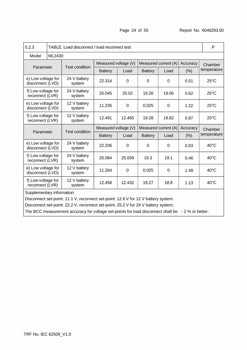
TRF No. IEC 62509_V1.0
12 V battery system:
10% 18.094 2.371 42.63 13.209 3.004 39.57 92.837
20% 17.706 4.733 83.8 13.2 6.087 80.34 95.871
30% 17.752 6.967 123.67 13.202 9.002 118.84 96.095
40% 17.714 9.346 165.54 13.207 12.018 158.72 95.877
50% 17.833 11.649 207.72 13.199 15.034 198.44 95.531
60% 17.742 14.145 250.95 13.206 18.076 239 95.123
70% 17.498 16.76 293.24 13.213 21.013 278 94.678
80% 17.925 18.742 335.94 13.203 23.973 317 94.222
90% 17.879 21.309 380.96 13.206 27.03 357 93.701
100% 17.962 23.752 426.6 13.221 30.062 397 93.166
Supplementary information:

Page 34 of 55 Report No. 6046293.50
TRF No. IEC 62509_V1.0
5.3.2 TABLE: Voltage Drop P
Model ML2420
Parameter Load Level Battery Voltage (V) Load Voltage (V)
24 V battery system No Load 26.406 26.416
24 V battery system 100% Load 26.411 26.114
Voltage drop between battery and load @ full load (V) 0.297
Parameter Load Level Battery Voltage (V) Load Voltage (V)
12 V battery system No Load 13.204 13.210
12 V battery system 100% Load 13.207 12.911
Voltage drop between battery and load @ full load (V) 0.296
Supplementary information:
5.3.2 TABLE: Voltage Drop P
Model ML2430
Parameter Load Level Battery Voltage (V) Load Voltage (V)
24 V battery system No Load 26.407 26.413
24 V battery system 100% Load 26.401 26.196
Voltage drop between battery and load @ full load (V) 0.205
Parameter Load Level Battery Voltage (V) Load Voltage (V)
12 V battery system No Load 13.203 13.209
12 V battery system 100% Load 13.207 12.998
Voltage drop between battery and load @ full load (V) 0.209
Supplementary information:

Page 35 of 55 Report No. 6046293.50
TRF No. IEC 62509_V1.0
5.3.2 TABLE: Voltage Drop P
Model ML2440
Parameter Load Level Battery Voltage (V) Load Voltage (V)
24 V battery system No Load 26.406 26.413
24 V battery system 100% Load 26.406 26.194
Voltage drop between battery and load @ full load (V) 0.212
Parameter Load Level Battery Voltage (V) Load Voltage (V)
12 V battery system No Load 13.203 13.209
12 V battery system 100% Load 13.204 12.993
Voltage drop between battery and load @ full load (V) 0.211
Supplementary information:
5.3.2 TABLE: Voltage Drop P
Model ML4830
Parameter Load Level Battery Voltage (V) Load Voltage (V)
24 V battery system No Load 52.806 52.816
24 V battery system 100% Load 52.805 52.676
Voltage drop between battery and load @ full load (V) 0.129
Parameter Load Level Battery Voltage (V) Load Voltage (V)
12 V battery system No Load 39.602 39.61
12 V battery system 100% Load 39.608 39.476
Voltage drop between battery and load @ full load (V) 0.132
Parameter Load Level Battery Voltage (V) Load Voltage (V)
24 V battery system No Load 26.406 26.413
24 V battery system 100% Load 26.407 26.274
Voltage drop between battery and load @ full load (V) 0.133
Parameter Load Level Battery Voltage (V) Load Voltage (V)
12 V battery system No Load 13.204 13.21
12 V battery system 100% Load 13.212 13.074
Voltage drop between battery and load @ full load (V) 0.138
Supplementary information:

Page 36 of 55 Report No. 6046293.50
TRF No. IEC 62509_V1.0
5.4.1 TABLE: Thermal performance test (Charge state with load output) P
Model ML2420
Test condition
PV Battery Load
Voltage (V)
Current (A)
Power (W)
Voltage (V)
Current (A)
Power (W)
Voltage (V)
Current (A)
Power (W)
24 V battery voltage
35.775 15.292 547 26.386 0.192 4.92 26.185 20.076 525.69
5.4.1 TABLE: Thermal performance test (Charge state without load output)
Test condition
PV Battery Load
Voltage (V)
Current (A)
Power (W)
Voltage (V)
Current (A)
Power (W)
Voltage (V)
Current (A)
Power (W)
24 V battery voltage
35.53 15.525 552 26.436 19.955 528 0 0 0
Supplementary information:
The test was performed on 24 V battery voltage also valid to 12 V battery voltage due to the have same current rating.
5.4.1 TABLE: Thermal performance test (Charge state with load output) P
Model ML2430
Test condition
PV Battery Load
Voltage (V)
Current (A)
Power (W)
Voltage (V)
Current (A)
Power (W)
Voltage (V)
Current (A)
Power (W)
24 V battery voltage
41.83 19.858 829 26.403 9.907 260 26.291 20.018 526
5.4.1 TABLE: Thermal performance test (Charge state without load output)
Test condition
PV Battery Load
Voltage (V)
Current (A)
Power (W)
Voltage (V)
Current (A)
Power (W)
Voltage (V)
Current (A)
Power (W)
24 V battery voltage
42.341 19.339 817 26.408 29.76 786 0 0 0
Supplementary information:
The test was performed on 24 V battery voltage also valid to 12 V battery voltage due to the have same current rating.

Page 37 of 55 Report No. 6046293.50
TRF No. IEC 62509_V1.0
5.4.1 TABLE: Thermal performance test (Charge state with load output) P
Model ML2440
Test condition
PV Battery Load
Voltage (V)
Current (A)
Power (W)
Voltage (V)
Current (A)
Power (W)
Voltage (V)
Current (A)
Power (W)
24 V battery voltage
41.26 30.253 1240 26.392 20.194 529 26.313 20.008 526
5.4.1 TABLE: Thermal performance test (Charge state without load output)
Test condition
PV Battery Load
Voltage (V)
Current (A)
Power (W)
Voltage (V)
Current (A)
Power (W)
Voltage (V)
Current (A)
Power (W)
24 V battery voltage
40.12 27.375 1100 26.452 39.710 1050 0 0 0
Supplementary information:
The test was performed on 24 V battery voltage also valid to 12 V battery voltage due to the have same current rating.
5.4.1 TABLE: Thermal performance test (Charge state with load output) P
Model ML4830
Test condition
PV Battery Load
Voltage (V)
Current (A)
Power (W)
Voltage (V)
Current (A)
Power (W)
Voltage (V)
Current (A)
Power (W)
48 V battery voltage
74.24 21.68 1610 52.803 9.708 513 52.713 19.932 1050
5.4.1 TABLE: Thermal performance test (Charge state without load output)
Test condition
PV Battery Load
Voltage (V)
Current (A)
Power (W)
Voltage (V)
Current (A)
Power (W)
Voltage (V)
Current (A)
Power (W)
48 V battery voltage
83.28 17.238 1440 52.794 26.538 1400 0 0 0
Supplementary information:
The test was performed on 48 V battery voltage also valid to 12/24/36 V battery voltage due to the have same current rating.

Page 38 of 55 Report No. 6046293.50
TRF No. IEC 62509_V1.0
5.4.2 TABLE: PV overcurrent protection test P
Model ML2420
Test condition PV Battery
Voltage (V) Current (A) Power (W) Voltage (V) Current (A) Power (W)
24 V battery voltage
39.921 14.778 589 26.407 21.305 562.6
Supplementary information:
The test was performed on 24 V battery voltage also valid to 12 V battery voltage due to the have same current rating.
5.4.2 TABLE: PV overcurrent protection test P
Model ML2430
Test condition PV Battery
Voltage (V) Current (A) Power (W) Voltage (V) Current (A) Power (W)
24 V battery voltage
42.21 19.587 825 26.404 30.09 794
Supplementary information:
The test was performed on 24 V battery voltage also valid to 12 V battery voltage due to the have same current rating.
5.4.2 TABLE: PV overcurrent protection test P
Model ML2430
Test condition PV Battery
Voltage (V) Current (A) Power (W) Voltage (V) Current (A) Power (W)
24 V battery voltage
41.29 27.131 1110 26.421 40.38 1070
Supplementary information:
The test was performed on 24 V battery voltage also valid to 12 V battery voltage due to the have same current rating.
5.4.2 TABLE: PV overcurrent protection test P
Model ML4830
Test condition PV Battery
Voltage (V) Current (A) Power (W) Voltage (V) Current (A) Power (W)
24 V battery voltage
84.66 19.294 1630 52.806 30.14 1590
Supplementary information:
The test was performed on 48 V battery voltage also valid to 12/24/36 V battery voltage due to the have same current rating.

Page 39 of 55 Report No. 6046293.50
TRF No. IEC 62509_V1.0
5.4.3 TABLE: Load over current protection test P
Model ML2420
Test condition Battery Load
Voltage (V) Current (A) Power (W) Voltage (V) Current (A) Power (W)
24V battery voltage
24.004 28.317 680 23.6 28.283 668
Supplementary information:
The test was performed on 24 V battery voltage also valid to 12 V battery voltage due to the have same current rating.
5.4.3 TABLE: Load over current protection test P
Model ML2430
Test condition Battery Load
Voltage (V) Current (A) Power (W) Voltage (V) Current (A) Power (W)
24V battery voltage
24.19 25.575 619 24.04 25.288 608
Supplementary information:
The test was performed on 24 V battery voltage also valid to 12 V battery voltage due to the have same current rating.
5.4.3 TABLE: Load over current protection test P
Model ML2440
Test condition Battery Load
Voltage (V) Current (A) Power (W) Voltage (V) Current (A) Power (W)
24V battery voltage
24.101 25.422 613 23.952 25.138 602
Supplementary information:
The test was performed on 24 V battery voltage also valid to 12 V battery voltage due to the have same current rating.
5.4.3 TABLE: Load over current protection test P
Model ML4830
Test condition Battery Load
Voltage (V) Current (A) Power (W) Voltage (V) Current (A) Power (W)
48V battery voltage
48.088 26.191 1260 47.933 25.924 1240
Supplementary information:
The test was performed on 48 V battery voltage also valid to 12/24/36 V battery voltage due to the have same current rating.

Page 40 of 55 Report No. 6046293.50
TRF No. IEC 62509_V1.0
5.4.4 TABLE: Battery reverse polarity test P
Model ML2420
Test condition
PV Battery Load
Voltage (V)
Current (A)
Power (W)
Voltage (V)
Current (A)
Power (W)
Power (W)
Current (A)
Power (W)
24 V battery voltage
36.09 0.016 0.58 26.363 0 0 0 0 0
12 V battery voltage
18.05 0.019 0.34 13.202 0 0 0 0 0
Supplementary information:
5.4.4 TABLE: Battery reverse polarity test P
Model ML2430
Test condition
PV Battery Load
Voltage (V)
Current (A)
Power (W)
Voltage (V)
Current (A)
Power (W)
Power (W)
Current (A)
Power (W)
24 V battery voltage
36.09 0.014 0.51 26.367 0 0 0 0 0
12 V battery voltage
18.05 0.02 0.36 13.21 0 0 0 0 0
Supplementary information:

Page 41 of 55 Report No. 6046293.50
TRF No. IEC 62509_V1.0
5.4.4 TABLE: Battery reverse polarity test P
Model ML2440
Test condition
PV Battery Load
Voltage (V)
Current (A)
Power (W)
Voltage (V)
Current (A)
Power (W)
Power (W)
Current (A)
Power (W)
24 V battery voltage
36.10 0.012 0.43 26.341 0 0 0 0 0
12 V battery voltage
18.05 0.023 0.42 13.195 0 0 0 0 0
Supplementary information:
5.4.4 TABLE: Battery reverse polarity test P
Model ML4830
Test condition
PV Battery Load
Voltage (V)
Current (A)
Power (W)
Voltage (V)
Current (A)
Power (W)
Power (W)
Current (A)
Power (W)
48 V battery voltage
72.19 0.009 0.65 52.873 0 0 0 0 0
36 V battery voltage
54.14 0.017 0.92 39.59 0 0 0 0 0
24 V battery voltage
36.10 0.02 0.72 26.444 0 0 0 0 0
12 V battery voltage
18.05 0.027 0.49 13.252 0 0 0 0 0
Supplementary information:
5.4.5 TABLE: PV generator reverse polarity test P
Model ML2420
Test condition
PV Battery Load
Voltage (V)
Current (A)
Power (W)
Voltage (V)
Current (A)
Power (W)
Voltage(V)
Current (A)
Power (W)
24 V battery voltage
35.997 0 0 25.961 19.228 -499.18 25.893 19.135 495.46
12 V battery voltage
18.07V 0 0.49 13.103 19.953 -261.45 12.999 19.671 255.7
Supplementary information:

Page 42 of 55 Report No. 6046293.50
TRF No. IEC 62509_V1.0
5.4.5 TABLE: PV generator reverse polarity test P
Model ML2430
Test condition
PV Battery Load
Voltage (V)
Current (A)
Power (W)
Voltage (V)
Current (A)
Power (W)
Voltage(V)
Current (A)
Power (W)
24 V battery voltage
36.001 0 0 26.337 19.609 -516.44 26.298 19.451 511.51
12 V battery voltage
17.996 0 0 13.189 19.993 -263.7 13.141 19.326 253.97
Supplementary information:
5.4.5 TABLE: PV generator reverse polarity test P
Model ML2440
Test condition
PV Battery Load
Voltage (V)
Current (A)
Power (W)
Voltage (V)
Current (A)
Power (W)
Voltage(V)
Current (A)
Power (W)
24 V battery voltage
36.002 0 0 26.175 19.778 -517.68 26.034 19.631 511.06
12 V battery voltage
17.996 0 0 13.175 19.975 -263.17 13.1 19.309 252.95
Supplementary information:
5.4.5 TABLE: PV generator reverse polarity test P
Model ML4830
Test condition
PV Battery Load
Voltage (V)
Current (A)
Power (W)
Voltage (V)
Current (A)
Power (W)
Voltage(V)
Current (A)
Power (W)
48 V battery voltage
72.009 0 0 52.776 19.805 -1045.22 52.623 19.606 1031.7
36 V battery voltage
54.004 0 0 39.587 19.823 -784.75 39.48 19.631 775.03
24 V battery voltage
36.002 0 0 26.377 19.712 -519.95 26.287 19.565 514.3
12 V battery voltage
17.995 0 0 13.198 19.845 -261.92 13.102 19.66 257.58
Supplementary information:

Page 43 of 55 Report No. 6046293.50
TRF No. IEC 62509_V1.0
Appendix: Pictures
ML2420 Front View
ML2420 Bottom View
Page 44 of 55 Report No. 6046293.50
TRF No. IEC 62509_V1.0
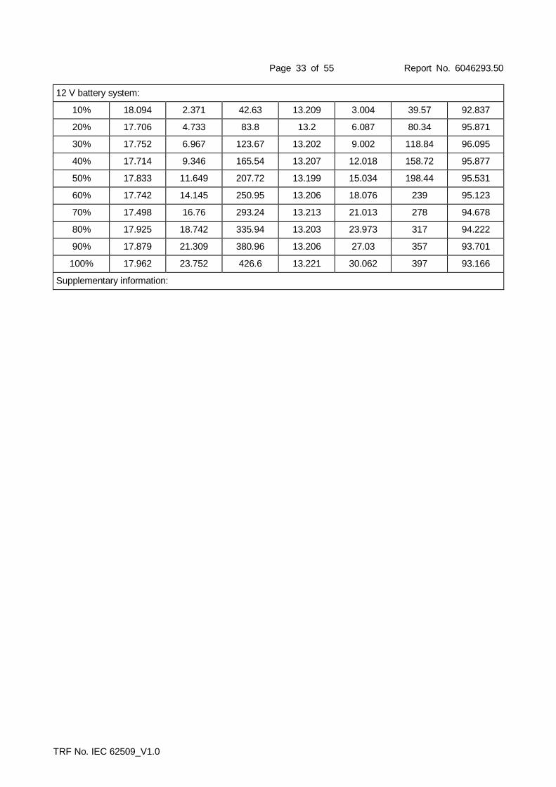
ML2420 Rear View
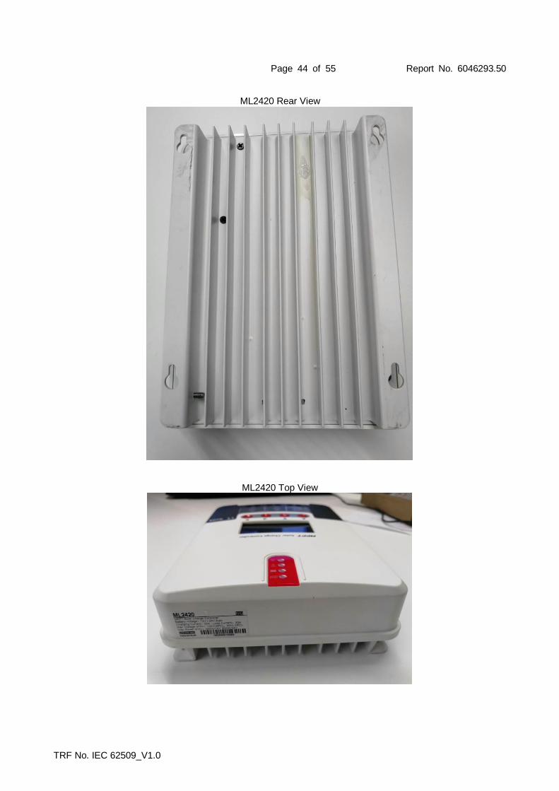
ML2420 Top View

Page 45 of 55 Report No. 6046293.50
TRF No. IEC 62509_V1.0
ML2430 / ML2440 Front View
ML2430 / ML2440 Bottom View

Page 46 of 55 Report No. 6046293.50
TRF No. IEC 62509_V1.0
ML2430 Rear View
ML2430 Top View

Page 47 of 55 Report No. 6046293.50
TRF No. IEC 62509_V1.0
ML2440 Rear View
ML2440 Top View

Page 48 of 55 Report No. 6046293.50
TRF No. IEC 62509_V1.0
ML4830 Front View
ML4830 Bottom View

Page 49 of 55 Report No. 6046293.50
TRF No. IEC 62509_V1.0
ML4830 Rear View
ML4830 Top View

Page 50 of 55 Report No. 6046293.50
TRF No. IEC 62509_V1.0
ML2420, ML2430, ML2440 Display Board - Component Side
ML2420, ML2430, ML2440 Display Board – Soldering Side

Page 51 of 55 Report No. 6046293.50
TRF No. IEC 62509_V1.0
ML2420 Main Board – Component Side
ML2420 Main Board –Soldering Side
Page 52 of 55 Report No. 6046293.50
TRF No. IEC 62509_V1.0
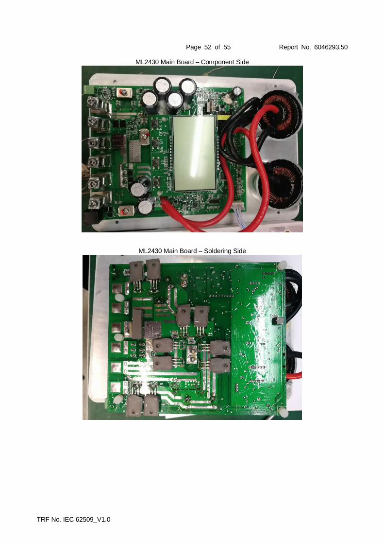
ML2430 Main Board – Component Side
ML2430 Main Board – Soldering Side

Page 53 of 55 Report No. 6046293.50
TRF No. IEC 62509_V1.0
ML2440 Main Board – Component Side
ML2430 Main Board – Soldering Side

Page 54 of 55 Report No. 6046293.50
TRF No. IEC 62509_V1.0
ML4830 Open View
ML4830 Display Board

Page 55 of 55 Report No. 6046293.50
TRF No. IEC 62509_V1.0
ML4830 Main Board – Component Side
ML4830 Main Board –Soldering Side
------------------------------------------------------------------END------------------------------------------------------------------------