Embed Size (px)
Citation preview

Page 1 of 95
Test Report
Hotpoint
Fridge Freezer
Model FF175B
Report No. 103250895MKS-001
Commercial-in-confidence
Client contact: Regulatory Delivery
Prepared by:
Report approved by:
Name: Michael Dyer
Title: Consultant Engineer
Name: Petr Bauer
Title: Laboratory Manager
Date: 12 February 2018
TESTED BY INTERTEK
This report is for the exclusive use of Intertek's Client and is provided pursuant to the agreement between Intertek and its Client. Intertek's responsibility and liability are limited to the terms and conditions of the agreement. Intertek assumes no liability to any party, other than to the Client in accordance with the agreement, for any loss, expense or damage occasioned by the use of this report. Only the Client is authorized to permit copying or distribution of this report and then only in its entirety. Any use of the Intertek name or one of its marks for the sale or advertisement of the tested material, product or service must first be approved in writing by Intertek. The observations and test results in this report are relevant only to the sample tested. This report by itself does not imply that the material, product, or service is or has ever been under an Intertek certification program.
Intertek Testing & Certification Ltd,
Registered office: Academy Place, 1-9 Brook Street, Brentwood, Essex, CM14 5NQ, United Kingdom
Registered No: 3272281 (England), VAT No: GB 672-7639-96-011.
Davy Avenue, Knowlhill
Milton Keynes
MK5 8NL, United Kingdom
Telephone: +44 1908 85 7777
www.intertek.com
Opinions and interpretations expressed herein are outside the scope of UKAS accreditation
Tests subcontracted to ITRi – who are UKAS accredited, but the ISO 9772 tests are not covered by their accreditation scope

TRF No. IEC60335_2_24F
Test Report issued under the responsibility of
TEST REPORT
IEC 60 335-2-24
Safety of household and similar electrical appliances
Part 2: Particular requirements for
refrigerating appliances, ice-cream appliances and ice-makers
Report reference No. .................. : 103250895MKS-001
Tested by (name + signature) ..... : Michal Dyer (Consultant Engineer)
Witnessed by (name + signature): N/A
Supervised by (name + signature): N/A
Approved by (name + signature) .. : Petr Bauer (Laboratory Manager)
Date of issue ............................... : 12 February 2018
Testing Laboratory ..................... : Intertek
Address ........................................ : Davy Avenue, Knowlhill, Milton Keynes, MK5 8NL, United Kingdom
Testing location/procedure ........... : CBTL RMT SMT WMT TMP
Address ........................................ : Same as above
Applicant’s Name ...................... : Regulatory Delivery
Address ....................................... : Regulatory Delivery, Stanton Avenue, Teddington, Middlesex, TW11 0JZ
Test specification
Standard ...................................... : EN 60335-2-24:2003 + A2:2007 in conj. with EN 60335-1:2002 + A2:2006
Test procedure ............................ : Intertek
Procedure deviation .................... : N/A
Non-standard test method ........... : N/A
Test Report Form IEC60335_2_24F (modified)
TRF originator. ............................ : SEV
Master TRF (date) ....................... : Dated 2005-08
Copyright 2005 IEC System for Conformity Testing and Certification of Electrical Equipment (IECEE), Geneva, Switzerland. All rights reserved. This publication may be reproduced in whole or in part for non-commercial purposes as long as the IECEE is acknowledged as copyright owner and source of the material. IECEE takes no responsibility for and will not assume liability for damages resulting from the reader’s interpretation of the reproduced material due to its placement and context. If this Test Report Form is used by non-IECEE members, the IECEE/IEC logo shall be removed
page 3 of 95 Report reference No: 103250895MKS-001
TRF No. IEC60335_2_24F
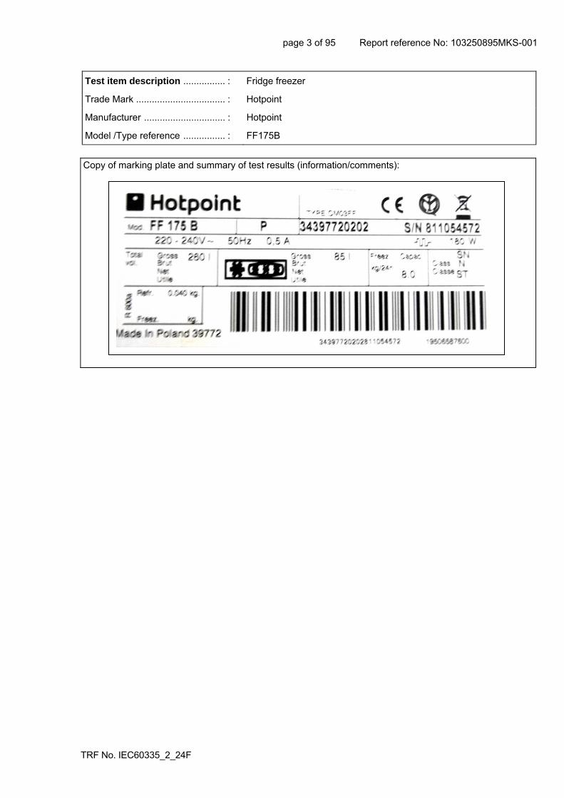
Test item description ................ : Fridge freezer
Trade Mark .................................. : Hotpoint
Manufacturer ............................... : Hotpoint
Model /Type reference ................ : FF175B
Copy of marking plate and summary of test results (information/comments):

page 4 of 95 Report reference No: 103250895MKS-001
TRF No. IEC60335_2_24F
Summary of testing:
Test of the fridge freezer was conducted against EN 60335-2-24:2003 + A2:2007 in conjunction with EN 60335-1:2002 + A2:2006; these being the current versions of the Standards at the time of appliance manufacture.
This test report must be read in conjunction with Intertek report 103250895LHD-002 which provides further narrative and context.
Within the attachment on page 82 covering European differences and national differences, a number of requirements relating to countries other than the United Kingdom have been noted as not assessed.
Nine samples of the fridge freezer were submitted with each assigned an identifying number from 1 to 9 inclusive. The majority of tests within this report were conducted on sample No. 2 which was fitted with a compressor manufactured by Embraco, model EMY66CLP with a compressor motor capacitor manufactured by Ducati, model 16.87.27, see attachment 2 on page 91 for further details.
The user instructions assessed consisted of 12 pages, with what appears to be a control/ident on page 12 of 195055538.01 dated 10/2006.
No component approvals were submitted to allow assessment of the requirements in Clause 24 (Components), and as such this clause has been marked within this report as not assessed and the components table 24 unfilled. For the purposes of this report it was assumed that the compressor was approved to EN 60335-2-34.
No circuit diagram for the control PCB was submitted to assist with test of the appliance, as a result there may be omissions within the abnormal operation tests of Clause 19 that would have otherwise been identified.
Test to the constructional requirements for a compression type appliance using a flammable refrigerant gas with an unprotected cooling system were conducted by Intertek’s Leatherhead HAZLOC facility – specifically clauses 22.108 and 22.109 with results held on file. These tests were conducted on the appliance assigned sample No 3, which was fitted with the same model compressor and compressor capacitor as sample No 2.
Clause 30.2 requires that non-metallic material shall be resistant to ignition and spread of fire. Parts made of soft or foamy materials are required to meet the flammability requirements of ISO 9772. However, the flammability tests are not conducted on parts unlikely to be ignited or to propagate flames that originate inside the appliance. Given that on the tested sample, bare foam insulation material was exposed within the rear compressor cavity, additional material testing was performed and is documented in the Attachment to this test report.
page 5 of 95 Report reference No: 103250895MKS-001
TRF No. IEC60335_2_24F
Test items particulars :
Classification of installation and use ............................ : Class I (with Class II construction), temperature Class SN, N and ST
Supply Connection ....................................................... : Non-detachable power cord fitted with mains plug (assessment based on type Y connection)
Possible test case verdicts :
Test case does not apply to the test object ................ : N/A
Test item does meet the requirement ........................ : P(ass)
Test item does not meet the requirement .................. : F(ail)
Testing
Date of receipt of test item ......................................... : 12 July 2017
Date(s) of performance of test.................................... : 19 July 2017 to 30 August 2017
Product verification per IECEE 02, Clause 6.2.5 . : Steps taken by the NCB to ensure that the products from all the factories stated in the CB Test Certificate are equal ............................................. :N/A
N/A
General remarks
The test results presented in this report relate only to the object tested. This report shall not be reproduced, except in full, without the written approval of the Issuing testing laboratory. This test report must be read in conjunction with Intertek report 103250895LHD-002 which provides further narrative and context.
"(see Enclosure #)" refers to additional information appended to the report. "(see appended table)" refers to a table appended to the report. Throughout this report a point is used as the decimal separator.
European Group Differences and National Differences – 4 pages
Attachment 1 - Photographs – 5 pages
Attachment 2 - machine configuration – 1 page
Attachment 3 - Standard gap analysis (standard differences between versions at the time of appliance manufacture and the present time) – 3 pages
Attachment 4 - Additional Clause 30.2.1 testing (1 page)
General product information:
The product tested is a used freestanding fridge freezer, model FF175B – originally manufactured in 2008.
It should be noted that at the time of test, the appliance tested was over 8 years old.
The appliance uses a flammable refrigerant gas, Isobutane (R-600a).

page 6 of 95 Report reference No: 103250895MKS-001
TRF No. IEC60335_2_24F
IEC 60 335-2-24
Clause Requirement – Test Result – Remark Verdict
5 GENERAL CONDITIONS FOR THE TESTS
Tests performed according to cl. 5, e.g. nature of supply, sequence of testing, etc.
P
5.3 Before starting the tests (IEC 60335-2-24:2002):
- ice cream appliances are operated empty of rated voltage for 1 h
N/A
- other compression-type appliances shall be operated at rated voltage for 24 h then switched off for 12 h
P
5.4 Tests are additionally carried out with all combinations of energy sources supplied simultaneously unless this is prevented by interlocking devices (IEC 60335-2-24:2002)
N/A
5.7 Tests according to sub-clause 10, 11,13 and subcl. 19.103 at ambient temperature of (IEC 60335-2-24:2002) :
(23 + 2) °C for ice-cream appliances N/A
(32 + 1) °C Climatic class SN P
(32 + 1) °C Climatic class N P
(38 + 1) °C Climatic class ST P
(43 + 1) °C Climatic class T N/A
5.102 Compression-type appliances with heating systems and Peltier-type appliances are tested as combined appliances (IEC 60335-2-24:2002)
N/A
6 CLASSIFICATION
6.1 Protection against electric shock: Class 0, 0I, I, II, III
Class I P
6.2 Protection against harmful ingress of water IPX0 N/A
6.101 Appliances, other than ice-cream appliances, shall be of one or more of the following climatic classes: SN, N, ST, T (IEC 60335-2-24:2002)
7 MARKING AND INSTRUCTIONS
7.1 Rated voltage or voltage range (V): 220-240 P
Nature of supply: ~ P
Rated frequency (Hz): 50 P
Rated power input (W): N/A
Rated current (A): 0.5 P
Manufacturer's or responsible vendor's name, trademark or identification mark:
Hotpoint P
Model or type reference: FF175B P

page 7 of 95 Report reference No: 103250895MKS-001
TRF No. IEC60335_2_24F
IEC 60 335-2-24
Clause Requirement – Test Result – Remark Verdict
Symbol 5172 of IEC 60417, for Class II appliances N/A
IP number, other than IPX0: N/A
Power input of heating systems, if greater than 100 W, (W) (IEC 60335-2-24:2002)
N/A
Defrosting input, in W, if greater than the rated power input, (W) (IEC 60335-2-24:2002)
180W P
Rated power input in Watts (IEC 60335-2-24:2002)
180W P
Rated current in Amperes for compression-type appliances (IEC 60335-2-24:2002)
P
Climatic class of the appliance (SN, N, ST or T) (IEC 60335-2-24:2002)
SN, N, ST P
Maximum rated input of lamps in Watts (IEC 60335-2-24:2002)
10W P
Total mass of the refrigerant (IEC 60335-2-24:2002)
0.04kg P
For a single component refrigerant, at least one of the following (IEC 60335-2-24:2002) :
- the chemical name N/A
- the chemical formula N/A
- the refrigerant number R-600a P
For a blended refrigerant, at least one of the following (IEC 60335-2-24:2002) :
- the chemical name and nominal proportion of each of the components
N/A
- the chemical formula and nominal proportion for each of the components
N/A
- the refrigerant numbers and nominal proportion of each of the components
N/A
- the refrigerant number of the refrigerant blend N/A
The chemical name or refrigerant number of the insulation blowing gas (IEC 60335-2-24:2002)
C Pentane P
Battery voltage for appliances which can be mains and battery operated (IEC 60335-2-24:2002)
N/A
Max. power input for incorporated ice-maker, if greater than 100 W (IEC 60335-2-24:2002)
N/A
Ice-makers shall be marked with the maximum permissible water level (IEC 60335-2-24:2002)
N/A
Compression-type refrigerating systems appliance shall be marked with mass of the refrigerant for each separate refrigerant circuit (IEC 60335-2-24:2002)
N/A

page 8 of 95 Report reference No: 103250895MKS-001
TRF No. IEC60335_2_24F
IEC 60 335-2-24
Clause Requirement – Test Result – Remark Verdict
Compression-type appliances flammable which use refrigerants shall be marked with warning sign B.3.2 from ISO 3864 (IEC 60335-2-24:2002)
P
A The enclosure of electrically-operated water valves incorporated in external hose-sets for connection of an appliance to the water mains shall be marked with symbol IEC 60417-5036 (DB:2002-10) if their working voltage exceeds extra-low voltage (IEC 60335-1:01 + A1:2004)
N/A
7.2 Warning for stationary appliances for multiple supply
N/A
Warning placed in vicinity of terminal cover N/A
7.3 Range of rated values marked with the lower and upper limits separated by a hyphen
P
Different rated values marked with the values separated by an oblique stroke
N/A
7.4 Appliances adjustable for different rated voltages, the voltage setting is clearly discernible
N/A
7.5 Appliances with more than one rated voltage or one or more rated voltage ranges, marked with rated input or rated current for each rated voltage or range, unless
N/A
the power input is related to the mean value of the rated voltage range
P
Relation between marking for upper and lower limits of rated power input or rated current and voltage is clear
N/A
7.6 Correct symbols used P
The perpendicular height of the triangle shall be at least 15 mm (IEC 60335-2-24:2002)
15mm P
7.7 Connection diagram fixed to appliances to be connected to more than two supply conductors and appliances for multiple supply
N/A
7.8 Except for type Z attachment, terminals for connection to the supply mains indicated as follows:
- marking of terminals exclusively for the neutral conductor (N)
P
- marking of protective earthing terminals (symbol 5019 of IEC 60417)
P
- marking not placed on removable parts On removable cover plate of the compressor (See Intertek Report 103250895LHD-002 for narrative)
F
7.9 Marking or placing of switches which may cause a hazard
N/A

page 9 of 95 Report reference No: 103250895MKS-001
TRF No. IEC60335_2_24F
IEC 60 335-2-24
Clause Requirement – Test Result – Remark Verdict
7.10 Indications of switches on stationary appliances and controls on all appliances by use of figures, letters or other visual means:
P
The figure 0 indicates only OFF position, unless no confusion with the OFF position
P
See Note (IEC 60335-2-24:2002) N/A
7.11 Indication for direction of adjustment of controls P
7.12 Instructions for safe use provided P
Instructions for refrigerating appliances and ice-makers for camping or similar use include the substance of the following (IEC 60335-2-24:2002) :
- suitable for camping use N/A
- the appliances connected to more than one source of energy
N/A
- the appliances shall not be exposed to rain unless at least IPX4
N/A
- for ice-makers not intended to be connected to the water supply
WARNING: fill with potable water only
N/A
For compression-type appliances which use flammable refrigerants, instructions shall include information pertaining to the installation, handling, servicing (IEC 60335-2-24:2002)
P
The instructions shall include the warnings (IEC 60335-2-24:2002)
See below (See Intertek Report 103250895LHD-002 for narrative)
F
WARNING – Keep ventilation openings, in the appliance enclosure or in the built-in structure, clear of obstruction (IEC 60335-2-24:2002)
P
WARNING – Do not use mechanical devices or other means to accelerate the defrosting process, other than those recommended by the manufacturer (IEC 60335-2-24:2002)
P
WARNING – Do not damage the refrigerant circuit (IEC 60335-2-24:2002)
No such warning (See Intertek Report 103250895LHD-002 for narrative)
F
WARNING – Do not use electrical appliances inside the food storage compartments of the appliance, unless they are of the type recommended by the manufacturer (IEC 60335-2-24:2002)
No such warning (See Intertek Report 103250895LHD-002 for narrative)
F
Appliances which use flammable insulation blowing gases, instructions shall include information regarding disposal of the appliance (IEC 60335-2-24:2002)
In Spanish P

page 10 of 95 Report reference No: 103250895MKS-001
TRF No. IEC60335_2_24F
IEC 60 335-2-24
Clause Requirement – Test Result – Remark Verdict
Instructions for ice-cream appliances shall include ingredients and max. quantity of mixtures that can be used in the appliance (IEC 60335-2-24:2002)
N/A
7.12.1 Sufficient details for installation supplied P
The method for replacing illuminating lamps included (IEC 60335-2-24:2002)
P
Appliances designed for incorporating ice-makers, the types of ice-makers (IEC 60335-2-24:2002)
N/A
Information on the installation of incorporated ice-makers as optional accessories (IEC 60335-2-24:2002)
N/A
Incorporated ice-makers installed only by the manufacturer or its service agent (IEC 60335-2-24:2002)
N/A
Ice makers intended to be connected to the water supply (IEC 60335-2-24:2002) :
- the maximum permissible inlet water pressure, (Pa) or (bar)
N/A
- the minimum permissible inlet water pressure, if necessary (Pa) or (bar)
N/A
WARNING: connect to potable water supply only (IEC 60335-2-24:2002)
N/A
Instructions for fixed appliances shall include the following warning (IEC 60335-2-24:2002) :
WARNING: To avoid a hazard due to instability of the appliance, it must be fixed in accordance with the instructions (IEC 60335-2-24:2002)
N/A
7.12.2 Stationary appliances not fitted with means for disconnection from the supply mains having a contact separation in all poles that provide full disconnection under overvoltage category III, the instructions state that means for disconnection must be incorporated in the fixed wiring in accordance with the wiring rules
Mains plug is disconnect device
N/A
7.12.3 Insulation of the fixed wiring in contact with parts exceeding 50 K during clause 11; instructions stating that the fixed wiring must be protected
N/A
7.12.4 Instructions for built-in appliances:
- dimensions of space N/A
- dimensions and position of supporting means N/A
- distances between parts and surrounding structure
N/A
- dimensions of ventilation openings and arrangement
N/A
- connection to supply mains and interconnection of separate components
N/A

page 11 of 95 Report reference No: 103250895MKS-001
TRF No. IEC60335_2_24F
IEC 60 335-2-24
Clause Requirement – Test Result – Remark Verdict
- plug accessible after installation, unless N/A
a switch complying with 24.3 N/A
Applicable to fixed appliances (IEC 60335-2-24:2002)
N/A
R - necessity to allow disconnection of the appliance from the supply after installation, unless the appliance incorporates a switch complying with 24.3 (IEC 60335-1:01 + A1:2004)
N/A
R - The disconnection may be achieved by having the plug accessible or by incorporating a switch in the fixed wiring in accordance with the wiring rules (IEC 60335-1:01 + A1:2004)
N/A
7.12.5 Replacement cord instructions, type X attachment with a specially prepared cord
N/A
Replacement cord instructions, type Y attachment P
Replacement cord instructions, type Z attachment N/A
7.12.6 A The instructions for heating appliances incorporating a non-self-resetting thermal cut-out that is reset by disconnection of the supply mains shall contain the substance of the following: (IEC 60335-1:01 + A1:2004)
N/A
A CAUTION: In order to avoid a hazard due to inadvertent resetting of the thermal cut-out, this appliance must not be supplied through an external switching device, such as a timer, or connected to a circuit that is regularly switched on and off by the utility. (IEC 60335-1:01 + A1:2004)
N/A
7.12.7 The instructions for fixed appliances shall state how the appliance is to be fixed to its support (IEC 60335-1:01 + A1:2004)
N/A
7.12.8 The instructions for appliances connected to the water mains shall state (IEC 60335-1:01 + A1:2004)
N/A
- the maximum inlet water pressure, in pascals; N/A
- the minimum inlet water pressure, in pascals, if this is necessary for the correct operation of the appliance.
N/A
The instructions for appliances connected to the water mains by detachable hose-sets shall state that the new hose-sets supplied with the appliance are to be used and that old hose-sets should not be reused. (IEC 60335-1:01 + A1:2004)
N/A
7.13 Instructions and other texts in an official language Disposal instructions in Spanish (See Intertek Report 103250895LHD-002 for narrative)
F

page 12 of 95 Report reference No: 103250895MKS-001
TRF No. IEC60335_2_24F
IEC 60 335-2-24
Clause Requirement – Test Result – Remark Verdict
7.14 Marking clearly legible and durable (IEC 60335-1:01 + A1:2004)
P
Hight of triangle symbol shall be at least 15 mm (IEC 60335-2-24:2003 + A2:2007)
P
7.15 Marking on a main part P
Marking clearly discernible from the outside, if necessary after removal of a cover
P
For portable appliances, cover can be removed or opened without a tool
N/A
For stationary appliances, name, trademark or identification mark and model or type reference visible after installation
N/A
For fixed appliances, name, trademark or identification mark and model or type reference visible after installation according to the instructions
N/A
Indications for switches and controls placed on or near the components. Marking not on parts which can be positioned or repositioned in such a way that the marking is misleading
P
Max. rated input of lamps discernible (IEC 60335-2-24:2002)
P
Compression-type appliances the marking of the type of flammable refrigerant and of the flammable insulation blowing gas, as well as the warning sign B.3.2 from ISO 3864, shall be visible when gaining access to the motor-compressors (IEC 60335-2-24:2002)
P
7.16 Marking of a possible replaceable thermal link or fuse link clearly visible regarding replacing the link
N/A
7.101 Appliances which can be battery operated the connection shall be indicated by the symbol “+” or the colour red and “-“ or black (IEC 60335-2-24:2002)
N/A
8 PROTECTION AGAINST ACCESS TO LIVE PARTS
8.1 Adequate protection against accidental contact with live parts
P
8.1.1 Requirement applies for all positions, detachable parts removed
P
Insertion or removal of lamps, protection against contact with live parts of the lamp cap
P
Use of test probe B of IEC 61032: no contact with live parts
P
Removal of lamps: protection against contact with live parts (IEC 60335-2-24:2002)
P

page 13 of 95 Report reference No: 103250895MKS-001
TRF No. IEC60335_2_24F
IEC 60 335-2-24
Clause Requirement – Test Result – Remark Verdict
8.1.2 Use of test probe 13 of IEC 61032 through openings in class 0 appliances and class II appliances/ constructions: no contact with live parts
P
Test probe 13 also applied through openings in earthed metal enclosures having a non-conductive coating: no contact with live parts
N/A
8.1.3 For appliances other than class II, use of test probe 41 of IEC 61032: no contact with live parts of visible glowing heating elements
N/A
8.1.4 Accessible part not considered live if:
- safety extra-low a.c. voltage: peak value not exceeding 42.4 V
N/A
- safety extra-low d.c. voltage: not exceeding 42.4 V
N/A
- or separated from live parts by protective impedance
N/A
If protective impedance: d.c. current not exceeding 2 mA, and
N/A
a.c. peak value not exceeding 0.7 mA N/A
- for peak values over 42.4 V up to and including 450 V, capacitance not exceeding 0,1 F
N/A
- for peak values over 450 V up to and including 15 kV, discharge not exceeding 45 C
N/A
The quantity of electricity in the discharge is measured using a resistor having a nominal non-inductive resistance of 2 000 Q. (IEC 60335-1:01 + A1:2004)
N/A
Number the existing note as Note 1 and add the following note: (IEC 60335-1:01 + A1:2004)
N/A
8.1.5 Live parts protected at least by basic insulation before installation or assembly:
- built-in appliances N/A
- fixed appliances N/A
- appliances delivered in separate units N/A
8.2 Class II appliances and constructions constructed so that there is adequate protection against accidental contact with basic insulation and metal parts separated from live parts by basic insulation only
P
Only possible to touch parts separated from live parts by double or reinforced insulation
P

page 14 of 95 Report reference No: 103250895MKS-001
TRF No. IEC60335_2_24F
IEC 60 335-2-24
Clause Requirement – Test Result – Remark Verdict
9 STARTING OF MOTOR-OPERATED APPLIANCES
Not applicable
10 POWER INPUT AND CURRENT
10.1 Power input at normal operating temperature, rated voltage and normal operation not deviating from rated power input by more than shown in table 1
N/A
Appliances being operated under normal operation, user adjustable temperature controls are set to give the lowest temperature (IEC 60335-2-24:2002)
N/A
The power input stabilized, steady conditions established (IEC 60335-2-24:2002)
N/A
A period between the making and the breaking of the temperature control, or highest and lowest values of power input measured (IEC 60335-2-24:2002)
N/A
10.2 Current at normal operating temperature, rated voltage and normal operation not deviating from rated current by more than shown in table 2
(see appended table) (See Intertek Report 103250895LHD-002 for narrative)
F
The appliance being operated under normal operation, user adjustable temperature controls are set to give the lowest temperature (IEC 60335-2-24:2002)
P
The appliance is operated for 1 h. The max. value of the current averaged over any 5 min period is obtained. The interval shall not exceed 30s. Starting after 1 min (IEC 60335-2-24:2002)
P
10.101 The power input of the defrosting system, deviation shown in table 1 (IEC 60335-2-24:2002)
165W P
10.102 The power input of any heating system, deviation shown in table 1 (IEC 60335-2-24:2002)
N/A
11 HEATING
11.1 No excessive temperatures in normal use P
If the winding temperatures of motor-compressors exceed the values given in table 101, compliance is checked by the test of 11.101 (IEC 60335-2-24:2002)
Approved compressor N/A
The winding temperatures of motor-compressors conforming IEC 60335-2-34 (incl. Annex AA) are not measured (IEC 60335-2-24:2002)
P
11.2 Placing and mounting of appliance as described (IEC 60335-2-24:2002)
P

page 15 of 95 Report reference No: 103250895MKS-001
TRF No. IEC60335_2_24F
IEC 60 335-2-24
Clause Requirement – Test Result – Remark Verdict
- according to instructions for installation N/A
- in a test corner N/A
- test enclosure P
11.3 Temperature rises, other than of windings, determined by thermocouples
P
Temperature rises of windings determined by resistance method, unless
N/A
the windings makes it difficult to make the necessary connections
P
11.4 Heating appliances operated under normal operation at 1.15 times rated power input:
N/A
11.5 Motor-operated appliances operated under normal operation at most unfavourable voltage between 0.94 and 1.06 times rated voltage:
N/A
11.6 Combined appliances operated under normal operation at most unfavourable voltage between 0.94 and 1.06 times rated voltage:
P
11.7 The appliances is operated until steady conditions are established (IEC 60335-2-24:2002)
P
11.8 Temperature rises not exceeding values in table 3 (see appended tables) P
During the test protective devices do not operate (IEC 60335-2-24:2002)
P
During the test sealing compound doesn’t flow out (IEC 60335-2-24:2002)
P
During the test temperatures are monitored conti- nuously (IEC 60335-2-24:2002)
P
For (SN) and (N) class, the temperature rises not exceeding values in table 3 (IEC 60335-2-24:2002)
P
For (ST) and (T) class, the temperature rises not exceeding values in table 3 reduced by 7 K (IEC 60335-2-24:2002)
P
The temperature rise of the external enclosure of motor-operated appliances not applicable for: (IEC 60335-2-24:2002)
- built-in appliances N/A
- other appliances (distance from a wall < 75 mm) P
- max. temperature rises specified in table 101 P
- temperatures are not measured for motor- compressors complying with (IEC 60 335-2-34) (IEC 60335-2-24:2002)
P

page 16 of 95 Report reference No: 103250895MKS-001
TRF No. IEC60335_2_24F
IEC 60 335-2-24
Clause Requirement – Test Result – Remark Verdict
A However, components in protective electronic circuits are allowed to operate provided they are tested for the number of cycles of operation specified in 24.1.4. (IEC 60335-1:01 + A1:2004)
N/A
A The temperature of ballast windings and their associated wiring shall not exceed the values specified in 12.4 of IEC 60598-1, when measured under the conditions stated. (IEC 60335-2-24:2002/A1:2005)
N/A
11.101 If the temperatures exceed the limits, the test is carried out again (IEC 60335-2-24:2002) :
- winding temperatures at the end of a running cycle not higher than the limits given in table 101
N/A
11.102 Any defrosting system, temperature rises don’t exceed the values given in 11.8 (IEC 60335-2-24:2002)
P
Manual defrosting (IEC 60335-2-24:2002) N/A
Automatic defrosting (IEC 60335-2-24:2002) P
11.103 Heating systems, other than defrosting, tempera- ture rises don’t exceed the values given in 11.8 (IEC 60335-2-24:2002)
N/A
13 LEAKAGE CURRENT AND ELECTRIC STRENGTH AT OPERATING TEMPERATURE
13.1 Leakage current not excessive and electric strength adequate
P
Heating appliances operated at 1.15 times rated power input:
N/A
Motor-operated appliances and combined appliances supplied at 1.06 times rated voltage:
P
Protective impedance and radio interference filters disconnected before carrying out the tests
N/A
The test of 13.2 does not apply to battery circuit (IEC 60335-2-24:2002)
N/A
13.2 Leakage current measured by means of the circuit described in figure 4 of IEC 60990
P
Leakage current measurements and limits (IEC 60335-2-24:2002)
(see appended table) P
13.3 Electric strength tests according to table 4 (see appended table) P
No breakdown during the tests P
page 17 of 95 Report reference No: 103250895MKS-001
TRF No. IEC60335_2_24F
IEC 60 335-2-24
Clause Requirement – Test Result – Remark Verdict
The test voltage for reinforced insulation is applied between separate circuits for battery operation and mains supply operation (IEC 60335-2-24:2002)
N/A
The appliance is disconnected from the supply and the insulation is immediately subjected to a voltage having a frequency of 50 Hz or 60 Hz for 1 min, in accordance with IEC 61180-1.(IEC 60335-1:01 + A1:2004)
P
The high-voltage source used for the test is to be capable of supplying a short circuit current ls between the output terminals after the output voltage has been adjusted to the appropriate test voltage. (IEC 60335-1:01 + A1:2004)
P
The overload release of the circuit is not to be operated by any current below the tripping current lr The values of ls and lr are given in Table 5 for various high-voltage sources. (IEC 60335-1:01 + A1:2004)
P
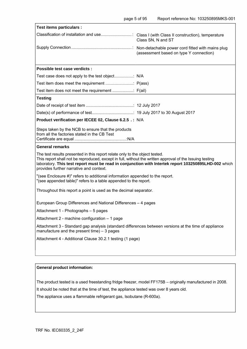
14 TRANSIENT OVERVOLTAGES
Appliances withstand the transient overvoltages to which they may be subjected
N/A
Clearances having a value less than specified in table 16 subjected to an impulse voltage test, the test voltage specified in table 6
N/A
No flashover during the test, unless of functional insulation
N/A
In case of flashover of functional insulation, the appliance complies with clause 19 with the clearance short circuited
N/A
15 MOISTURE RESISTANCE
15.1 Enclosure provides the degree of moisture protection according to classification of the appliance
P
Compliance checked as specified in 15.1.1, taking into account 15.1.2, followed by the electric strength test of 16.3
P
No trace of water on insulation which can result in a reduction of clearances and creepage distances below values specified in clause 29
P
15.1.1 Appliances, other than IPX0, subjected to tests as specified in IEC 60529:
N/A
page 18 of 95 Report reference No: 103250895MKS-001
TRF No. IEC60335_2_24F
IEC 60 335-2-24
Clause Requirement – Test Result – Remark Verdict
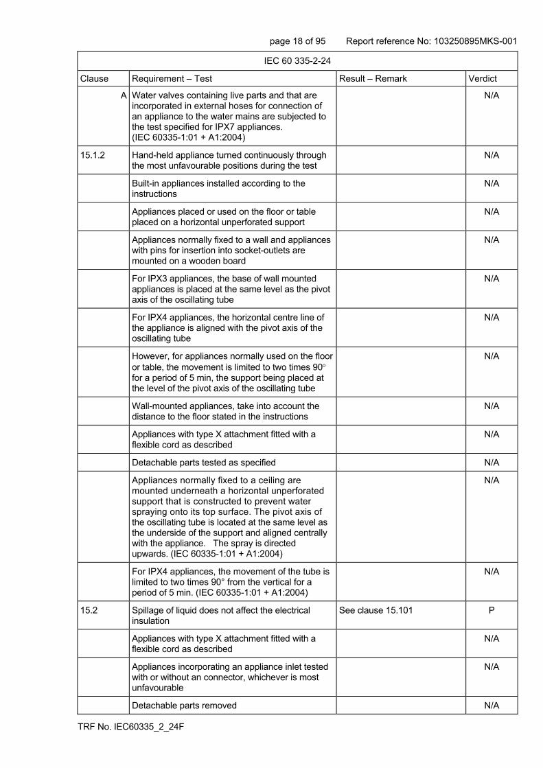
A Water valves containing live parts and that are incorporated in external hoses for connection of an appliance to the water mains are subjected to the test specified for IPX7 appliances. (IEC 60335-1:01 + A1:2004)
N/A
15.1.2 Hand-held appliance turned continuously through the most unfavourable positions during the test
N/A
Built-in appliances installed according to the instructions
N/A
Appliances placed or used on the floor or table placed on a horizontal unperforated support
N/A
Appliances normally fixed to a wall and appliances with pins for insertion into socket-outlets are mounted on a wooden board
N/A
For IPX3 appliances, the base of wall mounted appliances is placed at the same level as the pivot axis of the oscillating tube
N/A
For IPX4 appliances, the horizontal centre line of the appliance is aligned with the pivot axis of the oscillating tube
N/A
However, for appliances normally used on the floor or table, the movement is limited to two times 90 for a period of 5 min, the support being placed at the level of the pivot axis of the oscillating tube
N/A
Wall-mounted appliances, take into account the distance to the floor stated in the instructions
N/A
Appliances with type X attachment fitted with a flexible cord as described
N/A
Detachable parts tested as specified N/A
Appliances normally fixed to a ceiling are mounted underneath a horizontal unperforated support that is constructed to prevent water spraying onto its top surface. The pivot axis of the oscillating tube is located at the same level as the underside of the support and aligned centrally with the appliance. The spray is directed upwards. (IEC 60335-1:01 + A1:2004)
N/A
For IPX4 appliances, the movement of the tube is limited to two times 90° from the vertical for a period of 5 min. (IEC 60335-1:01 + A1:2004)
N/A
15.2 Spillage of liquid does not affect the electrical insulation
See clause 15.101 P
Appliances with type X attachment fitted with a flexible cord as described
N/A
Appliances incorporating an appliance inlet tested with or without an connector, whichever is most unfavourable
N/A
Detachable parts removed N/A

page 19 of 95 Report reference No: 103250895MKS-001
TRF No. IEC60335_2_24F
IEC 60 335-2-24
Clause Requirement – Test Result – Remark Verdict
Overfilling test with additional amount of water, over a period of 1 min (l):
N/A
The appliance withstands the electric strength test of 16.3
N/A
No trace of water on insulation that can result in a reduction of clearances and creepage distances below values specified in clause 29
N/A
Lamp covers are not removed (IEC 60335-2-24:2002)
N/A
15.3 Appliances proof against humid conditions P
Humidity test for 48 h in a humidity cabinet P
The appliance withstands the tests of clause 16 P
15.101 Spillage of liquid from inside does not affect their electrical insulation (IEC 60335-2-24:2002)
P
The relevant tests of 15.102, 15.103 and 15.104. are carried out (IEC 60335-2-24:2002)
P
15.102 The apparatus shown in figure 101 is filled with water containing 1% NaCl and 0,6% of acid rinsing agent (IEC 60335-2-24:2002)
P
15.103 Appliances, other than built-in appliances, ice-makers and ice-cream appliances, are tilted at an angle of up to 2° (IEC 60335-2-24:2002)
P
Test with 0,5 l water containing 1% NaCl and 0,6% of acid rinsing agent over the top of the appliance (IEC 60335-2-24:2002)
P
15.104 Ice-makers which are directly connected to the water supply, is filled with water as in normal use.The inlet valve is then held open for 1 min (IEC 60335-2-24:2002)
N/A
15.105 Operation of a defrosting system does not affect the electrical insulation of defrost heating elements (IEC 60335-2-24:2002)
P
If the water is in contact with the defrost heating element or its insulation, test of 22.102 is carried out (IEC 60335-2-24:2002)
N/A
16 LEAKAGE CURRENT AND ELECTRIC STRENGTH
16.1 Leakage current not excessive and electric strength adequate
P
Protective impedance disconnected from live parts before carrying out the tests
N/A
The test of 16.2 does not apply to battery circuits(IEC 60335-2-24:2002)
N/A
16.2 Single-phase appliances: test voltage 1.06 times rated voltage:
P
page 20 of 95 Report reference No: 103250895MKS-001
TRF No. IEC60335_2_24F
IEC 60 335-2-24
Clause Requirement – Test Result – Remark Verdict
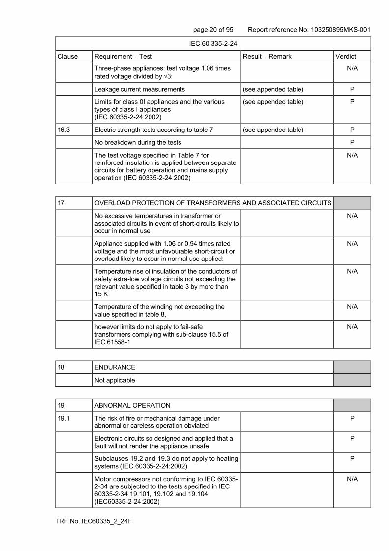
Three-phase appliances: test voltage 1.06 times rated voltage divided by 3:
N/A
Leakage current measurements (see appended table) P
Limits for class 0I appliances and the various types of class I appliances (IEC 60335-2-24:2002)
(see appended table) P
16.3 Electric strength tests according to table 7 (see appended table) P
No breakdown during the tests P
The test voltage specified in Table 7 for reinforced insulation is applied between separate circuits for battery operation and mains supply operation (IEC 60335-2-24:2002)
N/A
17 OVERLOAD PROTECTION OF TRANSFORMERS AND ASSOCIATED CIRCUITS
No excessive temperatures in transformer or associated circuits in event of short-circuits likely to occur in normal use
N/A
Appliance supplied with 1.06 or 0.94 times rated voltage and the most unfavourable short-circuit or overload likely to occur in normal use applied:
N/A
Temperature rise of insulation of the conductors of safety extra-low voltage circuits not exceeding the relevant value specified in table 3 by more than 15 K
N/A
Temperature of the winding not exceeding the value specified in table 8,
N/A
however limits do not apply to fail-safe transformers complying with sub-clause 15.5 of IEC 61558-1
N/A
18 ENDURANCE
Not applicable
19 ABNORMAL OPERATION
19.1 The risk of fire or mechanical damage under abnormal or careless operation obviated
P
Electronic circuits so designed and applied that a fault will not render the appliance unsafe
P
Subclauses 19.2 and 19.3 do not apply to heating systems (IEC 60335-2-24:2002)
P
Motor compressors not conforming to IEC 60335-2-34 are subjected to the tests specified in IEC 60335-2-34 19.101, 19.102 and 19.104 (IEC60335-2-24:2002)
N/A

page 21 of 95 Report reference No: 103250895MKS-001
TRF No. IEC60335_2_24F
IEC 60 335-2-24
Clause Requirement – Test Result – Remark Verdict
Fan motors of ice-cream appliances are not subject to the locked-rotor test specified in Annex (IEC 60335-2-24:2002)
N/A
19.2 A Controls that operate during the test of Clause 11 are allowed to operate (IEC 60335-1:01 + A1:2004)
19.3 A Controls that operate during the test of Clause 11 are allowed to operate (IEC 60335-1:01 + A1:2004)
19.4 Test conditions as in cl. 11, any control limiting the temperature during tests of cl. 11 short-circuited
P
19.5 Test of 19.4 repeated on Class 0I and I appliances with tubular sheathed or embedded heating elements. No short-circuiting, but one end of the element connected to the elements sheath
P
The test repeated with reversed polarity and the other end of the heating element connected to the sheath
P
The test is not carried out on appliances intended to be permanently connected to fixed wiring and on appliances where an all-pole disconnection occurs during the test of 19.4
P
19.6 Appliances with PTC heating elements tested at rated voltage, establishing steady conditions
N/A
The working voltage of the PTC heating element is increased by 5% and the appliance is operated until steady conditions are re-established. The voltage is then increased in similar steps until 1.5 times working voltage or until the PTC heating element ruptures
N/A
19.7 Stalling test by locking the rotor if the locked rotor torque is smaller than the full load torque or locking moving parts of other appliances
P
Locked rotor, motor capacitors open-circuited or short-circuited, if required
Approved compressor unit N/A
Locked rotor, capacitors open-circuited one at a time
N/A
Test repeated with capacitors short-circuited one at a time, if required
N/A
Appliances with timer or programmer supplied with rated voltage for each of the tests, for a period equal to the maximum period allowed
N/A
Other appliances supplied with rated voltage for a period as specified
N/A
Winding temperatures not exceeding values specified in table 8
(see appended table) Internal fan
P
Fan motors of ice-cream appliances are tested for 5 min (IEC 60335-2-24:2002)
N/A

page 22 of 95 Report reference No: 103250895MKS-001
TRF No. IEC60335_2_24F
IEC 60 335-2-24
Clause Requirement – Test Result – Remark Verdict
19.8 Three-phase motors operated at rated voltage with one phase disconnected
N/A
Three-phase motor compressors operated at rated voltage with one phase disconnected, unless complying with IEC 60335-2-34 (IEC 60335-2-24:2002)
N/A
19.9 Not applicable
19.10 Series motor operated at 1.3 times rated voltage for 1 min:
N/A
During the test, parts not being ejected from the appliance
N/A
19.11 Electronic circuits, compliance checked by evaluation of the fault conditions specified in 19.11.2 for all circuits or parts of circuits, unless they comply with the conditions specified in 19.11.1
S/C of varistor P
R Appliances incorporating a protective electronic circuit are subjected to the tests of 19.11.3 and 19.11.4. (IEC 60335-1:01 + A1:2004)
N/A
R Appliances having a switch with an off position obtained by electronic disconnection, or a switch that can place the appliance in a stand-by mode, are subjected to the tests of 19.11.4. (IEC 60335-1:01 + A1:2004)
N/A
19.11.1 Before applying the fault conditions a) to f) in 19.11.2, it is checked if circuits or parts of circuit meet both of the following conditions:
- the electronic circuit is a low-power circuit, that is, the maximum power at low-power points does not exceed 15 W according to the tests specified
N/A
- the protection against electric shock, fire hazard, mechanical hazard or dangerous malfunction in other parts of the appliance does not rely on the correct functioning of the electronic circuit
N/A
- the protection against electric shock, fire hazard, mechanical hazard or dangerous malfunction in other parts of the appliance does not rely on the correct functioning of the electronic circuit (IEC 60335-1:01 + A1:2004)
N/A
19.11.2 Fault conditions applied one at a time, the appliance operated under conditions specified in cl. 11, but supplied at rated voltage, the duration of the tests as specified:
a) short circuit of functional insulation if clearances or creepage distances are less than the values specified in 29
P
b) open circuit at the terminals of any component P
c) short circuit of capacitors, unless they comply with IEC 60384-14
P

page 23 of 95 Report reference No: 103250895MKS-001
TRF No. IEC60335_2_24F
IEC 60 335-2-24
Clause Requirement – Test Result – Remark Verdict
d) short circuit of any two terminals of an electronic component, other than integrated circuits. This fault condition is not applied between the two circuits of an optocoupler
P
e) failure of triacs in the diode mode N/A
f) failure of an integrated circuit. The possible hazardous situations of the appliance are assessed to ensure that safety does not rely on the correct functioning of such a component
N/A
In this case the possible hazardous (IEC 60335-1:01 + A1:2004)
N/A
R In each case, the test is ended if a non-self-resetting interruption of the supply occurs within the appliance (IEC 60335-1:01 + A1:2004)
N/A
19.11.3 If the appliance incorporates a protective electronic circuit which operates to ensure compliance with clause 19, the relevant test is repeated with a single fault simulated, as indicated in a) to f) of 19.11.2
N/A
During and after each test the following is checked:
- the temperature rise of the windings do not exceed the values specified in table 8
N/A
- the appliance complies with the conditions specified in 19.13
N/A
- any current flowing through protective impedance not exceeding the limits specified in 8.1.4
N/A
If a conductor of a printed board becomes open-circuited, the appliance is considered to have withstood the particular test, provided all three of the following conditions are met:
- the material of the printed circuit board withstands the burning test of annex E
N/A
- any loosened conductor does not reduce the clearances or creepage distances between live parts and accessible metal parts below the values specified in cl. 29
N/A
- the appliance withstands the tests of 19.11.2 with open-circuited conductor bridged
N/A
19.11.4 A Appliances having a switch with an off position obtained by electronic disconnection, or a switch that can be placed in the stand-by mode, are subjected to the tests of 19.11.4.1 to 19.11.4.7. The tests are carried out with the appliance supplied at rated voltage, the switch being set in the off position or in the stand-by mode. (IEC 60335-1:01 + A1:2004)
N/A

page 24 of 95 Report reference No: 103250895MKS-001
TRF No. IEC60335_2_24F
IEC 60 335-2-24
Clause Requirement – Test Result – Remark Verdict
A Appliances incorporating a protective electronic circuit are subjected to the tests of 19.11.4.1 to 19.11.4.7. The tests are carried out after the protective electronic circuit has operated during the relevant tests of Clause 19 except 19.2, 19.6 and 19.11.3. However, appliances that are operated for 30 s or 5 min during the test of 19.7 are not subjected to the tests for electromagnetic phenomena. (IEC 60335-1:01 + A1:2004)
N/A
A The tests are carried out with surge arresters disconnected, unless they incorporate spark gaps. (IEC 60335-1:01 + A1:2004)
N/A
A NOTE 1 If the appliance has several modes of operation, the tests are carried out with the appliance operating in each mode, if necessary. (IEC 60335-1:01 + A1:2004)
A NOTE 2 Appliances incorporating electronic controls complying with the IEC 60730 series are not exempt from the tests. (IEC 60335-1:01 + A1:2004)
19.11.4.1 The appliance is subjected to electrostatic discharges in accordance with IEC 61000-4-2, test level 4 being applicable. Ten discharges having a positive polarity and ten discharges having a negative polarity are applied at each preselected point. (IEC 60335-1:01 + A1:2004)
N/A
19.11.4.2 The appliance is subjected to radiated fields in accordance with IEC 61000-4-3, test level 3 being applicable. (IEC 60335-1:01 + A1:2004)
N/A
19.11.4.3 A The appliance is subjected to fast transient bursts in accordance with IEC 61000-4-4. (IEC 60335-1:01 + A1:2004)
N/A
A Test level 3 is applicable for signal and control lines. (IEC 60335-1:01 + A1:2004)
N/A
A Test level 4 is applicable for the power supply lines. (IEC 60335-1:01 + A1:2004)
N/A
A The bursts are applied for 2 min with a positive polarity and for 2 min with a negative polarity. (IEC 60335-1:01 + A1:2004)
N/A
A The power supply terminals of the appliance are subjected to voltage surges in accordance with IEC 61000-4-5, five positive impulses and five negative impulses being applied at the selected points. (IEC 60335-1:01 + A1:2004)
N/A
A Test level 3 is applicable for the line-to-line coupling mode, a generator having a source impedance of 2 Ω being used. (IEC 60335-1:01 + A1:2004)
N/A
A Test level 4 is applicable for the line-to-earth coupling mode, a generator having a source impedance of 12 Ω being used. (IEC 60335-1:01 + A1:2004)
N/A

page 25 of 95 Report reference No: 103250895MKS-001
TRF No. IEC60335_2_24F
IEC 60 335-2-24
Clause Requirement – Test Result – Remark Verdict
A Earthed heating elements in class I appliances are disconnected during this test. (IEC 60335-1:01 + A1:2004)
N/A
A NOTE: If a feedback system depends on inputs related to a disconnected heating element, an artificial network may be needed. (IEC 60335-1:01 + A1:2004)
A For appliances having surge arresters incorporating spark gaps, the test is repeated at a level that is 95 % of the flashover voltage. (IEC 60335-1:01 + A1:2004)
N/A
19.11.4.5 A The appliance is subjected to injected currents in accordance with IEC 61000-4-6, test level 3 being applicable. (IEC 60335-1:01 + A1:2004)
N/A
A During the test, all frequencies between 0,15 MHz to 80 MHz are covered. (IEC 60335-1:01 + A1:2004)
N/A
A NOTE The dwell time for each frequency is to be sufficient to observe a possible malfunction of the protective electronic circuit. (IEC 60335-1:01 + A1:2004)
19.11.4.6 A The appliance is subjected to voltage dips and interruptions in accordance with IEC 61000-4-11 (IEC 60335-1:01 + A1:2004)
N/A
A The durations specified in Table 1 of IEC 61000-4-11 are applied to each test level, the dips and interruptions being applied at zero crossing of the supply voltage. (IEC 60335-1:01 + A1:2004)
N/A
19.11.4.7 A The appliance is subjected to mains signals in accordance with IEC 61000-4-13, test level class 2 being applicable (IEC 60335-1:01 + A1:2004)
N/A
19.12 If the safety of the appliance for any of the fault conditions specified in 19.11.2 depends on the operation of a miniature fuse-link complying with IEC 60127, the test is repeated, measuring the current flowing through the fuse-link; measured current (A); rated current of the fuse-link (A):
N/A
19.13 During the tests the appliance does not emit flames, molten metal, poisonous or ignitable gas in hazardous amounts
P
Temperature rises not exceeding the values shown in table 9
(see appended table) P
Enclosures not deformed to such an extent that compliance with cl. 8 is impaired
P
If the appliance can still be operated it complies with 20.2
P
Insulation, other than of class III appliance, withstand the electric strength test of 16.3, the test voltage specified in table 4:
- basic insulation: P
- supplementary insulation: N/A

page 26 of 95 Report reference No: 103250895MKS-001
TRF No. IEC60335_2_24F
IEC 60 335-2-24
Clause Requirement – Test Result – Remark Verdict
- reinforced insulation: P
Temperature rises not exceeding the values shown in table 7 or 150 °C for housing of motor-compressors (IEC 60335-2-24:2002)
Approved compressor N/A
A The appliance does not undergo a dangerous malfunction, and (IEC 60335-1:01 + A1:2004)
P
A no failure of protective electronic circuits, if the appliance is still operable (IEC 60335-1:01 + A1:2004)
N/A
A Appliances tested with an electronic switch in the off position or in the stand-by mode, do not become operational (IEC 60335-1:01 + A1:2004)
N/A
19.101 Heating systems dimensioned and located properly and comply with 19.13 during and after the test (IEC 60335-2-24:2002)
N/A
19.102 Ice-makers and ice-cream appliances so constructed that they do not cause any risk and comply with 19.13 during and after the tests (IEC 60335-2-24:2002)
N/A
19.103 Appliances intended for camping and similar use tested on an inclined support (5°) and comply with 19.13 during and after the test (IEC 60335-2-24:2002)
N/A
19.104 Illuminating equipment shall not cause any fire hazard under abnormal operating conditions (IEC 60335-2-24:2002/A1:2005)
P
Test as specified (IEC 60335-2-24:2002/A1:2005)
P
Illuminating equipment having discharge lamps is operated under the fault conditions specified in items a), d) and e) of 12.5.1 of IEC 60598-1, the appliance being supplied at rated voltage (IEC 60335-2-24:2002/A1:2005)
N/A
During the test, surrounding plastic parts shall not show any distortion which may affect safety in the sense of this standard (IEC 60335-2-24:2002/A1:2005)
P
The temperature of ballast windings shall not exceed the values specified in 12.5 of IEC 60598-1 when measured under the conditions specified (IEC 60335-2-24:2002/A1:2005)
N/A
19.105 Appliances intended for battery operation properly constructed and comply with 19.13 during and after the test (IEC 60335-2-24:2002)
N/A

page 27 of 95 Report reference No: 103250895MKS-001
TRF No. IEC60335_2_24F
IEC 60 335-2-24
Clause Requirement – Test Result – Remark Verdict
20 STABILITY AND MECHANICAL HAZARDS
20.1 Adequate stability P
Tilting test through an angle of 10 (appliance placed on an inclined plane/horizontal plane); appliance does not overturn
N/A
Tilting test repeated on appliances with heating elements, angle of inclination increased to 15
N/A
Possible heating test in overturned position; temperature rise does not exceed values shown in table 9
N/A
Ice-cream appliances shall have adequate stability (IEC 60335-2-24:2002)
N/A
20.2 Moving parts adequately arranged or enclosed as to provide protection against personal injury
Fan P
Protective enclosures, guards and similar parts are non-detachable
P
Adequate mechanical strength and fixing of protective enclosures
P
Self-resetting thermal cut-outs and overcurrent protective devices not causing a hazard, by unexpected reclosure
N/A
Not possible to touch dangerous moving parts with test probe
P
20.101 Refrigeration appliances and ice-makers shall have adequate stability. Tests according to 20.102, 20.103 and 20.104 (IEC 60335-2-24:2002)
P
This requirement does not apply to built-in appliances (IEC 60335-2-24:2002)
N/A
20.102 Test with door opened to 90° (IEC60335-2-24:2002 + A1:05)
P
Test with door opened to 180° or to the limit of door stop (IEC60335-2-24:2002 + A1:05)
P
20.103 Test with one of the drawers is pulled to the most onerous out position (IEC 60335-2-24:2002)
P
Test with two drawers are pulled to the most onerous out position (IEC 60335-2-24:2002)
N/A
20.104 Test with sliding drawers accessible without opening a door (IEC 60335-2-24:2002)
N/A
Doors shelves are loaded as specified in 20.102 and opened 90° (IEC 60335-2-24:2002)
N/A

page 28 of 95 Report reference No: 103250895MKS-001
TRF No. IEC60335_2_24F
IEC 60 335-2-24
Clause Requirement – Test Result – Remark Verdict
21 MECHANICAL STRENGTH
Appliance has adequate mechanical strength and is constructed as to withstand rough handling
P
No damage after three blows applied to various parts of the enclosure, impact energy 0,5 ± 0,04 J
P
If necessary, supplementary or reinforced insulation subjected to the electric strength test of 16.3
N/A
If necessary, repetition of groups of three blows on a new sample
N/A
Covers of lamps within the appliance are considered likely to be damaged in normal use. Lamps are not tested (IEC 60335-2-24:2002)
P
21.1 R Compliance is checked by applying blows to the appliance in accordance with test Ehb of IEC 60068-2-75, the spring hammer test. (IEC 60335-1:01 + A1:2004)
P
R The appliance is rigidly supported and three blows, having an impact energy of 0,5 J, are applied to every point of the enclosure that is likely to be weak. (IEC 60335-1:01 + A1:2004)
P
21.2 Accessible parts of solid insulation shall have sufficient strength to prevent Penetration by sharp implements. (IEC 60335-1:01 + A1:2004)
N/A
A Compliance is checked by subjecting the insulation to the following test, unless the thickness of supplementary insulation is at least 1 mm and that of reinforced insulation is at least 2 mm. (IEC 60335-1:01 + A1:2004)
reinforced insulation >2mm N/A
A The insulation is raised to the temperature measured during the test of Clause 11. Its tip is rounded with a radius of 0,25 mm ± 0,02 mm. (IEC 60335-1:01 + A1:2004)
N/A
A The surface of the insulation is then scratched by means of a hardened steel pin, the end of which has the form of a cone with an angle of 40°. (IEC 60335-1:01 + A1:2004)
N/A
A The pin is held at an angle of 80° - 85° to the horizontal and loaded so that the force exerted along its axis is 10 N ±0,5 N. (IEC 60335-1:01 + A1:2004)
N/A
A The scratches are made by drawing the pin along the surface of the insulation at a speed of approximately 20 mm/s. (IEC 60335-1:01 + A1:2004)
N/A
A Two parallel scratches are made. (IEC 60335-1:01 + A1:2004)
N/A

page 29 of 95 Report reference No: 103250895MKS-001
TRF No. IEC60335_2_24F
IEC 60 335-2-24
Clause Requirement – Test Result – Remark Verdict
A They are spaced sufficiently apart so that they are not affected by each other, their length covering approximately 25 % of the length of the insulation. (IEC 60335-1:01 + A1:2004)
N/A
A Two similar scratches are made at 90° to the first pair without crossing them. (IEC 60335-1:01 + A1:2004)
N/A
A The test fingernail of Figure 7 is then applied to the scratched surface with a force of approximately 10 N. (IEC 60335-1:01 + A1:2004)
N/A
A No further damage, such as separation of the material, shall occur. (IEC 60335-1:01 + A1:2004)
N/A
A The insulation shall then withstand the electric strength test of 16.3. (IEC 60335-1:01 + A1:2004)
N/A
A The hardened steel pin is then applied perpendicularly with a force of 30 N ± 0,5 N to an unscratched part of the surface. (IEC 60335-1:01 + A1:2004)
N/A
A The insulation shall then withstand the electric strength test of 16.3 with the pin still applied and used as one of the electrodes (IEC 60335-1:01 + A1:2004)
N/A
21.101 Appliances for camping or similar use tested against the effects of dropping and vibration as specified (IEC 60335-2-24:2002)
N/A
21.102 Lamps are protected against mechanical shocks (IEC 60335-2-24:2002)
P
22 CONSTRUCTION
22.1 Appliance marked with the first numeral of the IP system, relevant requirements of IEC 60529 are fulfilled
IPX0 N/A
22.2 Stationary appliance: means to provide all-pole disconnection from the supply provided, the following means being available:
- a supply cord fitted with a plug P
- a switch complying with 24.3 N/A
- a statement in the instruction sheet that a disconnection incorporated in the fixed wiring is to be provided
N/A
- an appliance inlet N/A
Singe-pole switches and single-pole protective devices for the disconnection of heating elements in single-phase permanently connected class I appliances, connected in the phase conductor
N/A
22.3 Appliance provided with pins: no undue strain on socket-outlets
N/A

page 30 of 95 Report reference No: 103250895MKS-001
TRF No. IEC60335_2_24F
IEC 60 335-2-24
Clause Requirement – Test Result – Remark Verdict
Applied torque not exceeding 0.25 Nm N/A
Pull force of 50N to each pin after the appliance has being placed in the heating cabinet; when cooled to room temperature the pins are not displaced by more than 1mm
N/A
Each pin subjected to a tork of 0.4Nm; the pins are not rotating unless rotating does not impair compliance with the standard
N/A
22.4 Appliance for heating liquids and appliance causing undue vibration not provided with pins for insertion into socket-outlets
N/A
22.5 No risk of electric shock when touching the pins of the plug
P
R The appliance is supplied at rated voltage. Any switch is then placed in the off position and the appliance is disconnected from the supply mains at the instant of voltage peak. One second after disconnection, the voltage between the pins of the plug is measured with an instrument that does not appreciably affect the value to be measured (IEC 60335-1:01 + A1:2004)
P
22.6 Electrical insulation not affected by condensing water or leaking liquid
P
Electrical insulation of Class II appliances not affected in case of a hose rupture or seal leak
N/A
Thermostats are not in contact with the evaporator unless they are adequately protected (IEC 60335-2-24:2002)
P
Fluids don’t flow along parts such as stems and tubes of thermostats (IEC 60335-2-24:2002)
P
22.7 Compression-type appliances, including protective enclosures of a protected cooling system, using flammable refrigerants shall withstand (IEC 60335-2-24:2002)
- a pressure of 3,5 times the saturated vapour pressure (70 °C)
Requires a specially prepared sample
-
- a pressure of 5 times the saturated vapour pressure (20 °C)
Requires a specially prepared sample
-
22.8 Electrical connections not subject to pulling during cleaning of compartments to which access can be gained without the aid of a tool, and that are likely to be cleaned in normal use
P
22.9 Insulation, internal wiring, windings, commutators and slip rings not exposed to oil, grease or similar substances
P
Adequate insulating properties of oil or grease to which insulation is exposed
N/A
page 31 of 95 Report reference No: 103250895MKS-001
TRF No. IEC60335_2_24F
IEC 60 335-2-24
Clause Requirement – Test Result – Remark Verdict
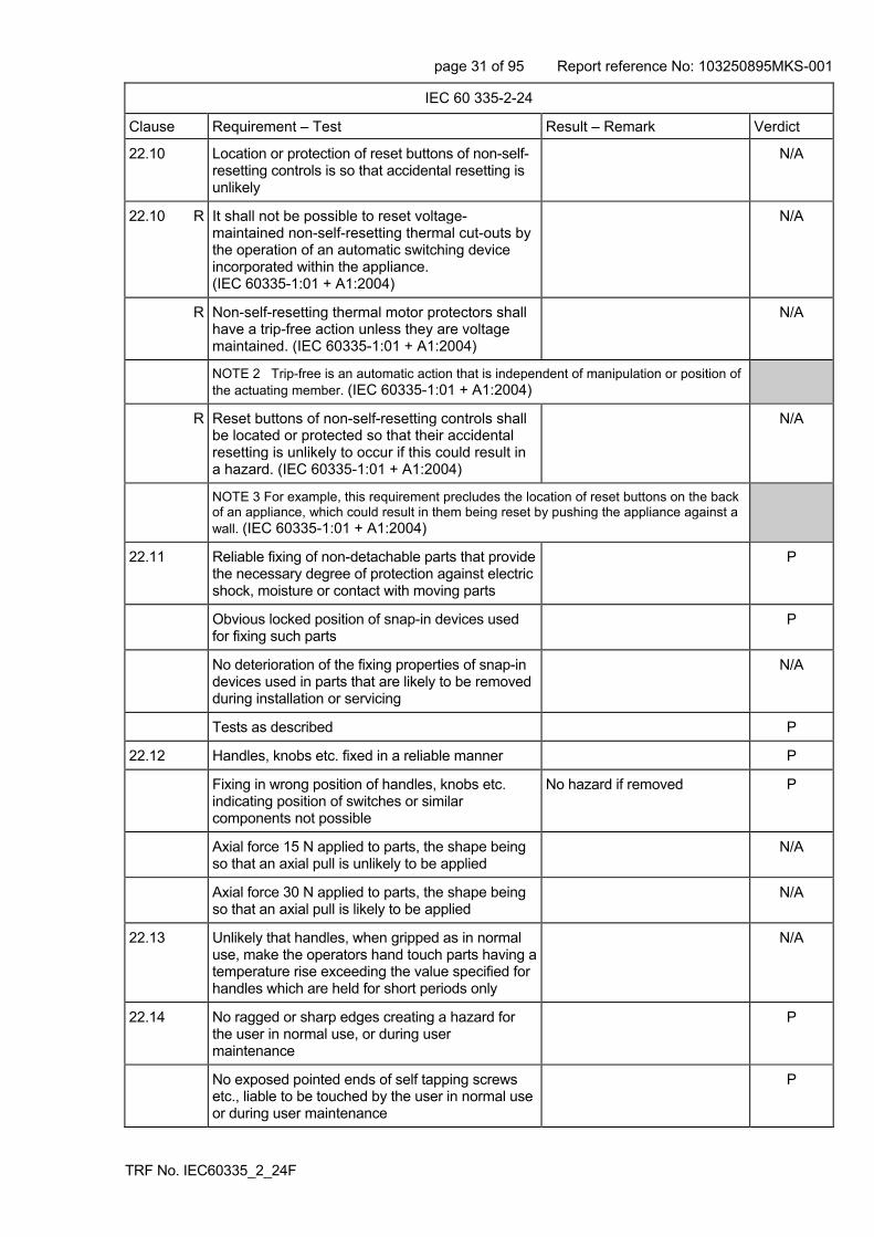
22.10 Location or protection of reset buttons of non-self-resetting controls is so that accidental resetting is unlikely
N/A
22.10 R It shall not be possible to reset voltage-maintained non-self-resetting thermal cut-outs by the operation of an automatic switching device incorporated within the appliance. (IEC 60335-1:01 + A1:2004)
N/A
R Non-self-resetting thermal motor protectors shall have a trip-free action unless they are voltage maintained. (IEC 60335-1:01 + A1:2004)
N/A
NOTE 2 Trip-free is an automatic action that is independent of manipulation or position of the actuating member. (IEC 60335-1:01 + A1:2004)
R Reset buttons of non-self-resetting controls shall be located or protected so that their accidental resetting is unlikely to occur if this could result in a hazard. (IEC 60335-1:01 + A1:2004)
N/A
NOTE 3 For example, this requirement precludes the location of reset buttons on the back of an appliance, which could result in them being reset by pushing the appliance against a wall. (IEC 60335-1:01 + A1:2004)
22.11 Reliable fixing of non-detachable parts that provide the necessary degree of protection against electric shock, moisture or contact with moving parts
P
Obvious locked position of snap-in devices used for fixing such parts
P
No deterioration of the fixing properties of snap-in devices used in parts that are likely to be removed during installation or servicing
N/A
Tests as described P
22.12 Handles, knobs etc. fixed in a reliable manner P
Fixing in wrong position of handles, knobs etc. indicating position of switches or similar components not possible
No hazard if removed P
Axial force 15 N applied to parts, the shape being so that an axial pull is unlikely to be applied
N/A
Axial force 30 N applied to parts, the shape being so that an axial pull is likely to be applied
N/A
22.13 Unlikely that handles, when gripped as in normal use, make the operators hand touch parts having a temperature rise exceeding the value specified for handles which are held for short periods only
N/A
22.14 No ragged or sharp edges creating a hazard for the user in normal use, or during user maintenance
P
No exposed pointed ends of self tapping screws etc., liable to be touched by the user in normal use or during user maintenance
P

page 32 of 95 Report reference No: 103250895MKS-001
TRF No. IEC60335_2_24F
IEC 60 335-2-24
Clause Requirement – Test Result – Remark Verdict
22.15 Storage hooks and the like for flexible cords smooth and well rounded
N/A
22.16 Automatic cord reels cause no undue abrasion or damage to the sheath of the flexible cord, no breakage of conductors strands, no undue wear of contacts
N/A
Cord reel tested with 6000 operations, as specified N/A
Electric strength test of 16.3, voltage of 1000 V applied
N/A
22.17 Spacers not removable from the outside by hand or by means of a screwdriver or a spanner
N/A
Not applicable to refrigeration appliances and ice-makers (IEC 60335-2-24:2002)
22.18 Current-carrying parts and other metal parts resistant to corrosion under normal conditions of use
P
22.19 Driving belts not used as electrical insulation N/A
22.20 Direct contact between live parts and thermal insulation effectively prevented, unless material used is non-corrosive, non-hygroscopic and non-combustible
P
Compliance is checked by inspection and, if necessary, by appropriate test
P
22.21 Wood, cotton, silk, ordinary paper and fibrous or hygroscopic material not used as insulation, unless impregnated
P
22.22 Appliances not containing asbestos P
22.23 Oils containing polychlorinated biphenyl (PCB) not used
P
22.24 Bare heating elements adequately supported N/A
In case of rupture, the heating conductor is unlikely to come in contact with accessible metal parts
N/A
22.25 Sagging heating conductors cannot come into contact with accessible metal parts
N/A
22.26 The insulation between parts operating at safety extra-low voltage and other live parts complies with the requirements for double or reinforced insulation
N/A
22.27 Parts connected by protective impedance separated by double or reinforced insulation
N/A
22.28 Metal parts of Class II appliances conductively connected to gas pipes or in contact with water: separated from live parts by double or reinforced insulation
N/A
22.29 Class II appliances permanently connected to fixed wiring so constructed that the required degree of access to live parts is maintained after installation
N/A

page 33 of 95 Report reference No: 103250895MKS-001
TRF No. IEC60335_2_24F
IEC 60 335-2-24
Clause Requirement – Test Result – Remark Verdict
22.30 Parts serving as supplementary or reinforced insulation fixed so that they cannot be removed without being seriously damaged, or
P
so constructed that they cannot be replaced in an incorrect position, and so that if they are omitted, the appliance is rendered inoperable or manifestly incomplete
P
22.31 TME Clearances and creepage distances over supplementary and reinforced insulation not reduced below values specified in clause 29 as result of war
P
TME Clearances and creeping distances between live parts and accessible parts not reduced below values for supplementary insulation, if wires, screws, etc. become loose
P
22.32 Supplementary and reinforced insulation designed or protected against deposition of dirt or dust
P
Supplementary insulation of natural or synthetic rubber resistant to ageing, or arranged and dimensioned so that creepage distances are not reduced below values specified in 29.2
N/A
Ceramic material not tightly sintered, similar material or beads alone not used as supplementary or reinforced insulation
N/A
Oxygen bomb test at 70 C for 96 h and 16 h at room temperature
N/A
22.33 Conductive liquids that are or may become accessible in normal use are not in direct contact with live parts
P
Electrodes not used for heating liquids P
For class II constructions, conductive liquids that are or may become accessible in normal use, not in direct contact with basic or reinforced insulation
P
For class II constructions, conductive liquids which are in contact with live parts, not in direct contact with reinforced insulation
N/A
Heating conductors having only one layer of insulation are not in direct contact with water or ice during normal use (IEC 60335-2-24:2002)
N/A
NOTE : Frozen water is regarded as a conducting liquid (IEC 60335-2-24:2002)
P
22.34 Shafts of operating knobs, handles, levers etc. not live, unless the shaft is not accessible when the part is removed
P
22.35 Handles, levers and knobs, held or actuated in normal use, not becoming live in the event of an insulation fault
P

page 34 of 95 Report reference No: 103250895MKS-001
TRF No. IEC60335_2_24F
IEC 60 335-2-24
Clause Requirement – Test Result – Remark Verdict
Such parts being of metal, and their shafts or fixings are likely to become live in the event of an insulation fault, they are either adequately covered by insulation material, or their accessible parts are separated from their shafts or fixings by supplementary insulation
N/A
This requirement does not apply to handles, levers and knobs on stationary appliances other than those of electrical components, provided they are either reliably connected to an earthing terminal or earthing contact, or separated from live parts by earthed metal
N/A
22.36 Handles continuously held in the hand in normal use are so constructed that when gripped as in normal use, the operators hand is not likely to touch metal parts, unless they are separated from live parts by double or reinforced insulation
N/A
22.37 Capacitors in Class II appliances not connected to accessible metal parts, unless complying with 22.42
N/A
Metal casings of capacitors in Class II appliances separated from accessible metal parts by supplementary insulation, unless complying with 22.42
N/A
22.38 Capacitors not connected between the contacts of a thermal cut-out
P
22.39 Lamp holders used only for the connection of lamps
P
22.40 Motor-operated appliances and combined appliances intended to be moved while in operation, or having accessible moving parts, fitted with a switch to control the motor. The actuating member of the switch being easily visible and accessible
N/A
22.41 No components, other than lamps, containing mercury
P
22.42 Protective impedance consisting of at least two separate components
N/A
Values specified in 8.1.4 not exceeded if any one of the components are short-circuited or open-circuited
N/A
22.43 Appliances adjustable for different voltages, accidental changing of the setting of the voltage unlikely to occur
N/A
22.44 Appliances are not allowed to have an enclosure that is shaped and decorated so that the appliance is likely to be treated as a toy by children
P
page 35 of 95 Report reference No: 103250895MKS-001
TRF No. IEC60335_2_24F
IEC 60 335-2-24
Clause Requirement – Test Result – Remark Verdict
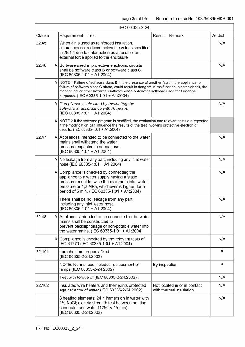
22.45 When air is used as reinforced insulation, clearances not reduced below the values specified in 29.1.4 due to deformation as a result of an external force applied to the enclosure
N/A
22.46 A Software used in protective electronic circuits shall be software class B or software class C. (IEC 60335-1:01 + A1:2004)
N/A
A NOTE 1 Failure of software class B in the presence of another fault in the appliance, or failure of software class C alone, could result in dangerous malfunction, electric shock, fire, mechanical or other hazards. Software class A denotes software used for functional purposes. (IEC 60335-1:01 + A1:2004)
A Compliance is checked by evaluating the software in accordance with Annex R. (IEC 60335-1:01 + A1:2004)
N/A
A NOTE 2 If the software program is modified, the evaluation and relevant tests are repeated if the modification can influence the results of the test involving protective electronic circuits. (IEC 60335-1:01 + A1:2004)
22.47 A Appliances intended to be connected to the water mains shall withstand the water pressure expected in normal use. (IEC 60335-1:01 + A1:2004)
N/A
A No leakage from any part, including any inlet water hose (IEC 60335-1:01 + A1:2004)
N/A
A Compliance is checked by connecting the appliance to a water supply having a static pressure equal to twice the maximum inlet water pressure or 1,2 MPa, whichever is higher, for a period of 5 min. (IEC 60335-1:01 + A1:2004)
N/A
There shall be no leakage from any part, including any inlet water hose. (IEC 60335-1:01 + A1:2004)
N/A
22.48 A Appliances intended to be connected to the water mains shall be constructed to prevent backsiphonage of non-potable water into the water mains. (IEC 60335-1:01 + A1:2004)
N/A
A Compliance is checked by the relevant tests of IEC 61770 (IEC 60335-1:01 + A1:2004)
N/A
22.101 Lampholders properly fixed (IEC 60335-2-24:2002)
P
NOTE: Normal use includes replacement of lamps (IEC 60335-2-24:2002)
By inspection P
Test with torque of (IEC 60335-2-24:2002) : N/A
22.102 Insulated wire heaters and their joints protected against entry of water (IEC 60335-2-24:2002)
Not located in or in contact with thermal insulation
N/A
3 heating elements: 24 h immersion in water with 1% NaCl; electric strength test between heating conductor and water (1250 V 15 min) (IEC 60335-2-24:2002)
N/A

page 36 of 95 Report reference No: 103250895MKS-001
TRF No. IEC60335_2_24F
IEC 60 335-2-24
Clause Requirement – Test Result – Remark Verdict
22.104 Appliances with two or more temperature control devices controlling the same motor-compressor don’t cause undue operation of the thermal motor-protector (IEC 60335-2-24:2002)
N/A
The test is carried out separately with each combination of control devices (IEC 60335-2-24:2002)
N/A
22.105 Appliances which can also be battery operated, the battery circuit is insulated from live parts by double insulation or reinforced insulation (IEC 60335-2-24:2002)
N/A
It is not possible to touch live parts when making the connections to the battery (IEC 60335-2-24:2002)
N/A
Specified for double insulation or reinforced insulation (IEC 60335-2-24:2002)
N/A
22.106 The mass of refrigerant (flammable refrigerant) shall not exceed 150g (IEC 60335-2-24:2002)
P
22.107 Compression-type appliances with a protected cooling system and which use flammable refrigerants shall be constructed to avoid any fire or explosion hazard, in the event of leakage of the cooling system (IEC 60335-2-24:2002)
N/A
22.107.1 A leakage is simulated at the most critical point of the cooling system (method as specified) (IEC60335-2-24:2002 + A1:05)
N/A
The measured value shall not exceed 75% LEL of the refrigerant (table 102) and shall not exceed 50% LEL for a period exceeding 5 min. (IEC 60335-2-24:2002)
N/A
22.107.2 All accessible surfaces of protected cooling system components, are scratched using the tool whose tip is shown in figure 102 (IEC 60335-2-24:2002)
N/A
The tool is applied using the following parameters (IEC 60335-2-24:2002) :
- force at right angles to the surface to be tested 35 N + 3 N
N/A
- force parallel to the surface to be tested 250 N N/A
The appropriate part shall withstand the test of 22.7 reduced by 50% (IEC 60335-2-24:2002)
N/A
22.108 Compression-type appliances with unprotected cooling systems and which use flammable refrigerants, any electrical apparatus other than non-self resetting protective devices, shall be tested and found to comply with the requirementsin Annex CC for group IIA gases or the refrigerant used (IEC60335-2-24:2002 + A1:05)
P

page 37 of 95 Report reference No: 103250895MKS-001
TRF No. IEC60335_2_24F
IEC 60 335-2-24
Clause Requirement – Test Result – Remark Verdict
Refrigerant leakage into food storage shall not result in an explosive atmosphere outside the food storage compartment in areas where electrical apparatus are mounted, except in those areas which contain only non-self resetting protective devices, necessary for compliance with the requirements in Annex CC for group IIA gases or the refrigerant used (IEC60335-2-24:2002 + A1:05)
P
The measured value shall not exceed 75% LEL of the refrigerant (table 102) and shall not exceed 50% LEL for a period exceeding 5 min (IEC60335-2-24:2002 + A1:05)
P
22.109 Compression-type appliance which use flammable refrigerants shall be constructed so that leaked refrigerant will not stagnate so as to cause a fire hazard in areas outside the food storage compartments where the appliance’s electrical components, other than non-self-resetting protective devices necessary for compliance with clause 19, are fitted (IEC60335-2-24:2002 + A1:05)
P
Unless the electrical components comply least with the requirements in Annex CC for group IIA gases or the refrigerant used (IEC60335-2-24:2002 + A1:05)
N/A
Test: A quantity equal to 50% + 1,5g of the refrigerant charge is injected into the considered area (IEC 60335-2-24:2002)
P
The measured value shall not exceed 75% LEL of the refrigerant (table 102) and shall not exceed 50% LEL for a period exceeding 5 min (IEC60335-2-24:2002 + A1:05)
P
22.110 Temperatures on surfaces be exposed to leakage of flammable refrigerants shall not exceed the ignition temperature (table 102) reduced by 100 K(IEC 60335-2-24:2002)
P
22.111 Doors and lids of compartments in appliances with a free space shall be capable of being opened from the inside (IEC 60335-2-24:2002)
P
The door shall open before the force exceeds 70 N (IEC 60335-2-24:2002)
P
22.112 Drawers which are only accessible after openings a door or lid shall not contain a free space (IEC 60335-2-24:2002)
P
22.113 Drawers which are accessible with out opening a door and which contain a free space shall have an opening in their rear wall and be capable of being opened from the inside (IEC 60335-2-24:2002)
N/A
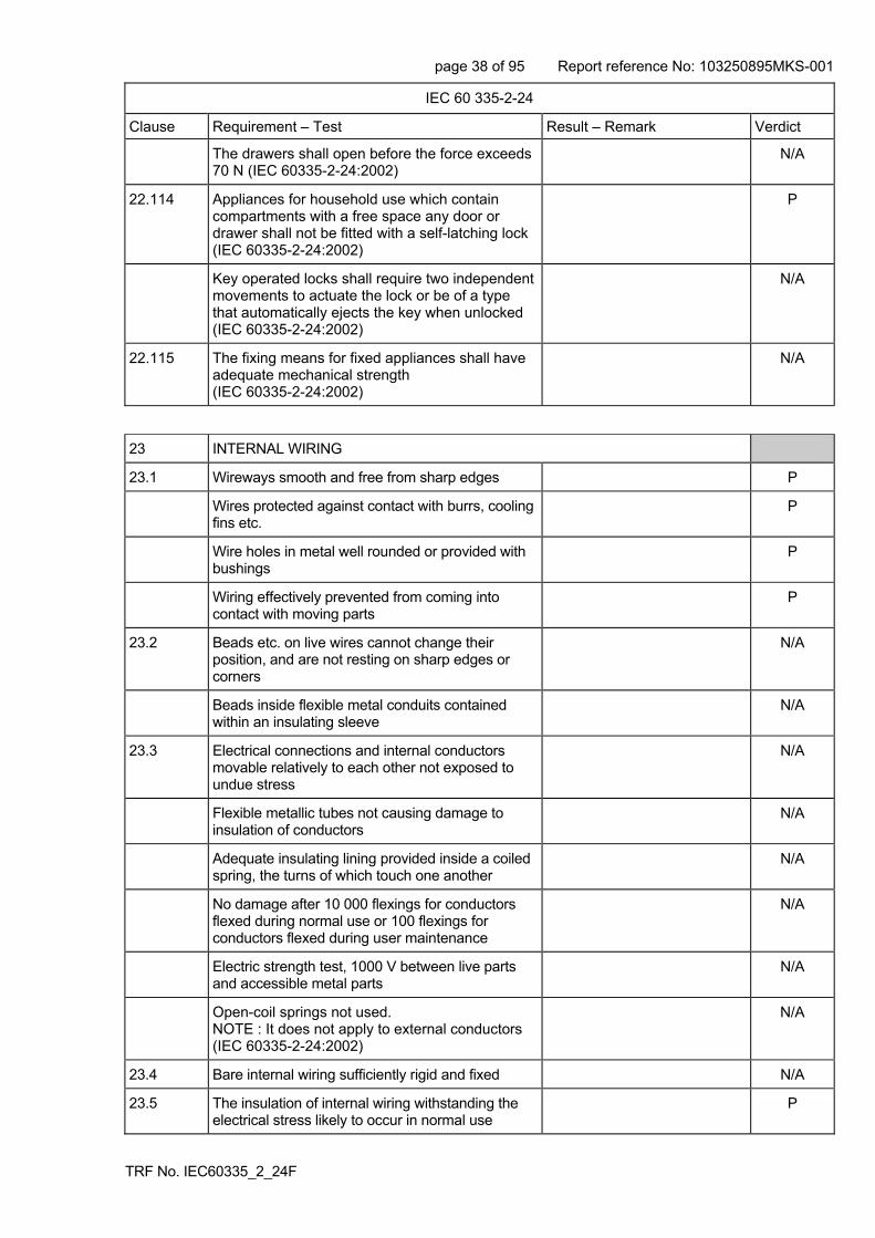
page 38 of 95 Report reference No: 103250895MKS-001
TRF No. IEC60335_2_24F
IEC 60 335-2-24
Clause Requirement – Test Result – Remark Verdict
The drawers shall open before the force exceeds 70 N (IEC 60335-2-24:2002)
N/A
22.114 Appliances for household use which contain compartments with a free space any door or drawer shall not be fitted with a self-latching lock (IEC 60335-2-24:2002)
P
Key operated locks shall require two independent movements to actuate the lock or be of a type that automatically ejects the key when unlocked (IEC 60335-2-24:2002)
N/A
22.115 The fixing means for fixed appliances shall have adequate mechanical strength (IEC 60335-2-24:2002)
N/A
23 INTERNAL WIRING
23.1 Wireways smooth and free from sharp edges P
Wires protected against contact with burrs, cooling fins etc.
P
Wire holes in metal well rounded or provided with bushings
P
Wiring effectively prevented from coming into contact with moving parts
P
23.2 Beads etc. on live wires cannot change their position, and are not resting on sharp edges or corners
N/A
Beads inside flexible metal conduits contained within an insulating sleeve
N/A
23.3 Electrical connections and internal conductors movable relatively to each other not exposed to undue stress
N/A
Flexible metallic tubes not causing damage to insulation of conductors
N/A
Adequate insulating lining provided inside a coiled spring, the turns of which touch one another
N/A
No damage after 10 000 flexings for conductors flexed during normal use or 100 flexings for conductors flexed during user maintenance
N/A
Electric strength test, 1000 V between live parts and accessible metal parts
N/A
Open-coil springs not used. NOTE : It does not apply to external conductors (IEC 60335-2-24:2002)
N/A
23.4 Bare internal wiring sufficiently rigid and fixed N/A
23.5 The insulation of internal wiring withstanding the electrical stress likely to occur in normal use
P

page 39 of 95 Report reference No: 103250895MKS-001
TRF No. IEC60335_2_24F
IEC 60 335-2-24
Clause Requirement – Test Result – Remark Verdict
No breakdown when a voltage of 2000 V is applied for 15 min between the conductor and metal foil wrapped around the insulation
P
23.6 Sleeving used as supplementary insulation on internal wiring retained in position by positive means
N/A
23.7 The colour combination green/yellow used only for earthing conductors
P
23.8 Aluminium wires not used for internal wiring P
23.9 No lead-tin soldering of stranded conductors where they are subject to contact pressure, unless
P
clamping means so constructed that there is no risk of bad contact due to cold flow of the solder
N/A
23.10 A The insulation and sheath of internal wiring, incorporated in external hoses for the connection of an appliance to the water mains, shall be at least equivalent to that of light polyvinyl chloride sheathed flexible cord (code designation 60227 IEC 52) (IEC 60335-1:01 + A1:2004)
N/A
A NOTE The mechanical characteristics specified in IEC 60227 are not evaluated. (IEC 60335-1:01 + A1:2004)
24 COMPONENTS
24.1 Components comply with safety requirements in relevant IEC standards
No component approval details submitted – see summary of testing on page 4.
-
List of components Not assessed -
Components not tested and found to comply with relevant IEC standard for the number of cycles specified are tested in accordance with 24.1.1 to 24.1.6
Not assessed -
Components not tested and found to comply with relevant IEC standard, components not marked or not used in accordance with its marking, tested under the conditions occurring in the appliance
Not assessed -
Motor-compressors are not required to be separately tested according to (IEC 60 335-2-34) nor are they required to meet the requirements of (IEC 60 335-2-34) if they meet the requirements of this standard (IEC 60335-2-24:2002)
Not assessed -
A Motors are not required to comply with IEC 60034-1. (IEC 60335-1:01 + A1:2004)
Not assessed -
24.1.1 Capacitors likely to be permanently subjected to the supply voltage and used for radio interference suppression or for voltage dividing, complying with IEC 60384-14, or
Not assessed -
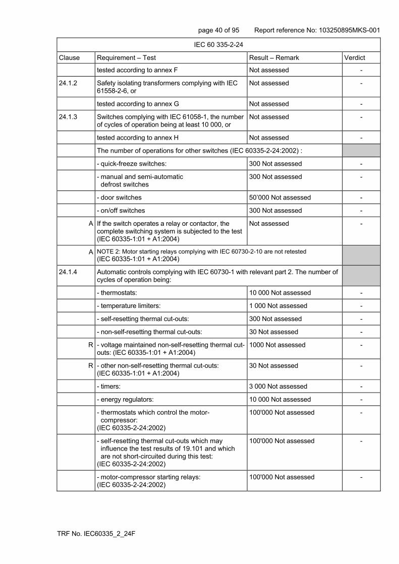
page 40 of 95 Report reference No: 103250895MKS-001
TRF No. IEC60335_2_24F
IEC 60 335-2-24
Clause Requirement – Test Result – Remark Verdict
tested according to annex F Not assessed -
24.1.2 Safety isolating transformers complying with IEC 61558-2-6, or
Not assessed -
tested according to annex G Not assessed -
24.1.3 Switches complying with IEC 61058-1, the number of cycles of operation being at least 10 000, or
Not assessed -
tested according to annex H Not assessed -
The number of operations for other switches (IEC 60335-2-24:2002) :
- quick-freeze switches: 300 Not assessed -
- manual and semi-automatic defrost switches
300 Not assessed -
- door switches 50’000 Not assessed -
- on/off switches 300 Not assessed -
A If the switch operates a relay or contactor, the complete switching system is subjected to the test(IEC 60335-1:01 + A1:2004)
Not assessed -
A NOTE 2: Motor starting relays complying with IEC 60730-2-10 are not retested (IEC 60335-1:01 + A1:2004)
24.1.4 Automatic controls complying with IEC 60730-1 with relevant part 2. The number of cycles of operation being:
- thermostats: 10 000 Not assessed -
- temperature limiters: 1 000 Not assessed -
- self-resetting thermal cut-outs: 300 Not assessed -
- non-self-resetting thermal cut-outs: 30 Not assessed -
R - voltage maintained non-self-resetting thermal cut-outs: (IEC 60335-1:01 + A1:2004)
1000 Not assessed -
R - other non-self-resetting thermal cut-outs: (IEC 60335-1:01 + A1:2004)
30 Not assessed -
- timers: 3 000 Not assessed -
- energy regulators: 10 000 Not assessed -
- thermostats which control the motor- compressor: (IEC 60335-2-24:2002)
100'000 Not assessed -
- self-resetting thermal cut-outs which may influence the test results of 19.101 and which are not short-circuited during this test: (IEC 60335-2-24:2002)
100'000 Not assessed -
- motor-compressor starting relays: (IEC 60335-2-24:2002)
100'000 Not assessed
-

page 41 of 95 Report reference No: 103250895MKS-001
TRF No. IEC60335_2_24F
IEC 60 335-2-24
Clause Requirement – Test Result – Remark Verdict
- automatic thermal motor-protectors for motor- compressors of the hermetic and semi-hermetic type: minimum 2000, but not less than the number of operations during the locked-rotor test (IEC 60335-2-24:2002)
Not assessed -
- manual reset thermal motor-protectors for motor-compressors of the hermetic and semi- hermetic type: 50 (IEC 60335-2-24:2002)
Not assessed -
- other automatic thermal motor-protectors: (IEC 60335-2-24:2002)
2000 Not assessed -
- other manual test thermal motor protectors: (IEC 60335-2-24:2002)
30 Not assessed -
A NOTE 3 The ambient temperature during the test of Clause 17 of IEC 60730-1 is that occurring during the test of Clause 11 in the appliance, as specified in footnote b of Table 3. (IEC 60335-1:01 + A1:2004)
R Thermal motor protectors are tested in combination with their motor under the conditions specified in Annex D (IEC 60335-1:01 + A1:2004)
Not assessed -
R For water valves containing live parts and that are incorporated in external hoses for connection of an appliance to the water mains, the degree of protection declared for subclause 6.5.2 of IEC 60730-2-8 is IPX7 (IEC 60335-1:01 + A1:2004)
Not assessed -
24.1.5 Appliance couplers complying with IEC 60320-1 Not assessed -
However, appliances classified higher than IPX0, the appliance couplers complying with IEC 60320-2-3
Not assessed -
24.1.6 Small lamp holders similar to E10 lampholders complying with IEC 60238, the requirements for E10 lampholders being applicable
Not assessed -
24.2 No switches or automatic controls in flexible cords Not assessed -
No devices causing the protective device in the fixed wiring to operate in the event of a fault in the appliance
Not assessed -
No thermal cut-outs that can be reset by soldering Not assessed -
24.3 Switches intended for all-pole disconnection of stationary appliances are directly connected to the supply terminals and having a contact separation in all poles, providing full disconnection under overvoltage category III conditions
Not assessed -
Appliances for camping or similar use (IEC 60335-2-24:2002) :
Voltage selection switches used in appliances for camping or similar use shall have a contact separation in all poles that provide full disconnection from the supply under overvoltage category III conditions (IEC 60335-2-24:2002)
Not assessed -

page 42 of 95 Report reference No: 103250895MKS-001
TRF No. IEC60335_2_24F
IEC 60 335-2-24
Clause Requirement – Test Result – Remark Verdict
24.4 Plugs and socket-outlets for extra-low voltage circuits and heating elements, not interchangeable with plugs and socket-outlets listed in IEC 60083 or IEC 60906-1 or with connectors and appliance inlets complying with the standard sheets of IEC 60320-1
Not assessed -
24.5 Capacitors in auxiliary windings of motors marked with their rated voltage and capacitance and used accordingly
Not assessed -
Voltage across capacitors in series with a motor winding does not exceed 1,1 times rated voltage, when the appliance is supplied at 1,1 times rated voltage under minimum load
Not assessed -
For starting capacitors, the voltage across the capacitors shall not exceed 1,3 times the rated voltage of the capacitor at 1.1xUn (IEC 60335-2-24:2002)
Not assessed -
24.6 Working voltage of motors connected to the supply mains and having basic insulation that is inadequate for the rated voltage of the appliance, not exceeding 42V.
Not assessed -
In addition, the motors are complying with the requirements of Annex I
Not assessed -
24.7 A Hose-sets for connection of appliances to the water mains, complying with IEC 61770 and supplied with the appliance (IEC 60335-1:01 + A1:2004)
Not assessed -
24.101 Lampholders shall be of the insulated type (IEC 60335-2-24:2002)
Not assessed -
25 SUPPLY CONNECTION AND EXTERNAL FLEXIBLE CORDS
Motor-compressors with facilities for connecting a supply cord, complying with the appropriate requirements of IEC 60 335-2-34 are not subjects to the following tests (IEC 60335-2-24:2002)
P
25.1 Appliance not intended for permanent connection to fixed wiring, means for connection to the supply:
- supply cord fitted with a plug P
- an appliance inlet having at least the same degree of protection against moisture as required for the appliance
N/A
- pins for insertion into socket-outlets N/A
25.2 Appliance not provided with more than one means of connection to the supply mains
P
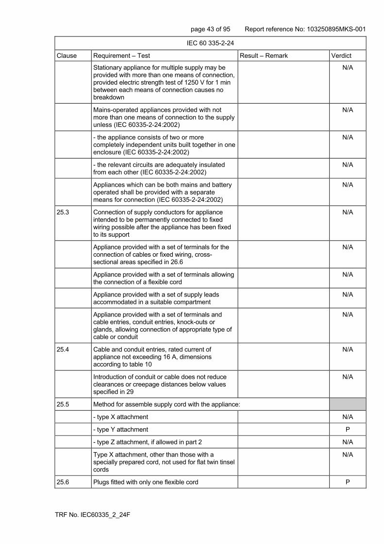
page 43 of 95 Report reference No: 103250895MKS-001
TRF No. IEC60335_2_24F
IEC 60 335-2-24
Clause Requirement – Test Result – Remark Verdict
Stationary appliance for multiple supply may be provided with more than one means of connection, provided electric strength test of 1250 V for 1 min between each means of connection causes no breakdown
N/A
Mains-operated appliances provided with not more than one means of connection to the supply unless (IEC 60335-2-24:2002)
N/A
- the appliance consists of two or more completely independent units built together in one enclosure (IEC 60335-2-24:2002)
N/A
- the relevant circuits are adequately insulated from each other (IEC 60335-2-24:2002)
N/A
Appliances which can be both mains and battery operated shall be provided with a separate means for connection (IEC 60335-2-24:2002)
N/A
25.3 Connection of supply conductors for appliance intended to be permanently connected to fixed wiring possible after the appliance has been fixed to its support
N/A
Appliance provided with a set of terminals for the connection of cables or fixed wiring, cross-sectional areas specified in 26.6
N/A
Appliance provided with a set of terminals allowing the connection of a flexible cord
N/A
Appliance provided with a set of supply leads accommodated in a suitable compartment
N/A
Appliance provided with a set of terminals and cable entries, conduit entries, knock-outs or glands, allowing connection of appropriate type of cable or conduit
N/A
25.4 Cable and conduit entries, rated current of appliance not exceeding 16 A, dimensions according to table 10
N/A
Introduction of conduit or cable does not reduce clearances or creepage distances below values specified in 29
N/A
25.5 Method for assemble supply cord with the appliance:
- type X attachment N/A
- type Y attachment P
- type Z attachment, if allowed in part 2 N/A
Type X attachment, other than those with a specially prepared cord, not used for flat twin tinsel cords
N/A
25.6 Plugs fitted with only one flexible cord P

page 44 of 95 Report reference No: 103250895MKS-001
TRF No. IEC60335_2_24F
IEC 60 335-2-24
Clause Requirement – Test Result – Remark Verdict
25.7 Supply cord not lighter than:
- braided cord (60245 IEC 51) N/A
- ordinary tough rubber sheathed cord (60245 IEC 53)
N/A
- flat twin tinsel cord (60227 IEC 41) N/A
- ordinary polyvinyl chloride sheathed cord (60227 IEC 53), appliance exceeding 3 kg
H05VV-F P
Temperature rise of external metal parts exceeding 75 K, PVC cord not used, unless
N/A
appliance so constructed that the supply cord is not likely to touch external metal parts in normal use, or
N/A
the supply cord is appropriate for higher temperatures, type Y or type Z attachment used
N/A
Appliance supply cord other then SELV power supply not lighter than (IEC 60335-2-24:2002) :
- light polyvinyl chloride sheathed cord (code designation 60227 IEC 52)
N/A
25.8 Nominal cross-sectional area of supply cords according to table 11; rated current (A); cross-sectional area (mm²):
0.5A, 0.75mm2 P
25.9 Supply cord not in contact with sharp points or edges
P
25.10 Green/yellow core for earthing purposes in Class I appliance
P
25.11 Conductors of supply cords not consolidated by lead-tin soldering where they are subject to contact pressure, unless
P
clamping means so constructed that there is no risk of bad contacts due to cold flow of the solder
N/A
25.12 Moulding the cord to part of the enclosure does not damage the insulation of the supply cord
N/A
25.13 Inlet opening so shaped as to prevent damage to the supply cord
P
Unless the enclosure at the inlet opening is of insulation material, a non-detachable lining or bushing complying with 29.3 for supplementary insulation provided
N/A
If unsheathed supply cord, a similar additional bushing or lining is required, unless
N/A
the appliance is class 0 N/A
Does not apply to flexible leads used to connected an appliance to a SELV power supply(IEC 60335-2-24:2002)
N/A

page 45 of 95 Report reference No: 103250895MKS-001
TRF No. IEC60335_2_24F
IEC 60 335-2-24
Clause Requirement – Test Result – Remark Verdict
25.14 Supply cords adequately protected against excessive flexing
N/A
Flexing test:
- applied force (N): N/A
- number of flexings: N/A
The test does not result in:
- short circuit between the conductors N/A
- breakage of more than 10% of the strands of any conductor
N/A
- separation of the conductor from its terminal N/A
- loosening of any cord guard N/A
- damage, within the meaning of the standard, to the cord or the cord guard
N/A
- broken strands piercing the insulation and becoming accessible
N/A
25.15 Conductors of the supply cord relieved from strain, twisting and abrasion by use of cord anchorage
P
The cord cannot be pushed into the appliance to such an extent that the cord or internal parts of the appliance can be damaged
P
Pull and torque test of supply cord, values shown in table 10: pull (N); torque (not on automatic cord reel) (Nm) :
P
Max. 2 mm displacement of the cord, and conductors not moved more than 1 mm in the terminals
P
Creepage distances and clearances not reduced below values specified in 29.1
P
25.16 Cord anchorages for type X attachments constructed and located so that:
- replacement of the cord is easily possible N/A
- it is clear how the relief from strain and the prevention of twisting are obtained
N/A
- they are suitable for different types of cord N/A
- cord cannot touch the clamping screws of cord anchorage if these screws are accessible, unless separated from accessible metal parts by supplementary insulation
N/A
- the cord is not clamped by a metal screw which bears directly on the cord
N/A
- at least one part of the cord anchorage securely fixed to the appliance, unless part of a specially prepared cord
N/A

page 46 of 95 Report reference No: 103250895MKS-001
TRF No. IEC60335_2_24F
IEC 60 335-2-24
Clause Requirement – Test Result – Remark Verdict
- screws which have to be operated when replacing the cord do not fix any other component, if applicable
N/A
- if labyrinths can be bypassed the test of 25.15 is nevertheless withstood
N/A
- for Class 0, 0I and I appliances: they are of insulating material or are provided with an insulating lining, unless a failure of the insulation of the cord does not make accessible metal parts live
N/A
- for Class II appliances: they are of insulating material, or if of metal, they are insulated from accessible metal parts by supplementary insulation
N/A
25.17 Adequate cord anchorages for type Y and Z attachment
P
25.18 Cord anchorages only accessible with the aid of a tool, or
N/A
so constructed that the cord can only be fitted with the aid of a tool
P
A25.19 Type X attachment, glands not used as cord anchorage in portable appliances
N/A
Tying the cord into a knot or tying the cord with string not used
N/A
25.20 Conductors of the supply cord for type Y and Z attachment adequately additionally insulated
P
25.21 Space for supply cord for type X attachment or for connection of fixed wiring constructed to permit checking of conductors with respect to correct positioning and connection before fitting any cover, no risk of damage to the conductors when fitting the cover, no contact with accessible metal parts if a conductor becomes loose, etc.
N/A
For portable appliances, the uninsulated end of a conductor prevented from any contact with accessible metal parts, unless the end of the cord is such that the conductors are unlikely to slip free
N/A
25.22 Appliance inlet:
- live parts not accessible during insertion or removal
N/A
- connector can be inserted without difficulty N/A
- the appliance is not supported by the connector N/A
- is not for cold conditions if temp. rise of external metal parts exceeds 75 K, unless the supply cord is not likely to touch such metal parts
N/A
25.23 Interconnection cords comply with the requirements for the supply cord, except as specified
N/A

page 47 of 95 Report reference No: 103250895MKS-001
TRF No. IEC60335_2_24F
IEC 60 335-2-24
Clause Requirement – Test Result – Remark Verdict
If necessary, electric strength test of 16.3 N/A
Interconnection cord for battery operated appliances (IEC 60335-2-24:2002)
N/A
25.24 Interconnection cords not detachable without the aid of a tool if compliance with the standard is impaired when they are disconnected
N/A
25.25 Dimensions of pins compatible with the dimensions of the relevant socket-outlet. Dimensions of pins and engagement face in accordance with the relevant plug in IEC 60083
N/A
25.101 Appliances which can be battery operated shall have suitable means for connection of the battery(IEC 60335-2-24:2002)
N/A
26 TERMINALS FOR EXTERNAL CONDUCTORS
This clause of part 1 is not applicable to those parts of motor-compressors with facilities for connecting a supply cord and complying with IEC 60 335-2-34 (IEC 60335-2-24:2002)
Part of approved compressor P
26.1 Appliances provided with terminals or equally effective devices for connection of external conductors
N/A
Terminals only accessible after removal of a non-detachable cover
N/A
A However, earthing terminals may be accessible if a tool is required to make the connections and means are provided to clamp the wire independently from its connection (IEC 60335-1:01 + A1:2004)
N/A
26.2 Appliances with type X attachment and appliances for connection to fixed wiring provided with terminals in which connections are made by means of screws, nuts or similar devices, unless the connections are soldered
N/A
Screws and nuts serve only to clamp supply conductors, except
N/A
internal conductors, if so arranged that they are unlikely to be displaced when fitting the supply conductors
N/A
If soldered connections used, the conductor so positioned or fixed that reliance is not placed on soldering alone
N/A
Soldering alone used, barriers provided, clearances and creepage distances satisfactory if the conductor becomes free at the soldered joint
N/A

page 48 of 95 Report reference No: 103250895MKS-001
TRF No. IEC60335_2_24F
IEC 60 335-2-24
Clause Requirement – Test Result – Remark Verdict
26.3 Terminals for type X attachment and for connection to fixed wiring so constructed that the conductor is clamped between metal surfaces with sufficient contact pressure and without damaging the conductor
N/A
Terminals for type X attachment and those for connection to fixed wiring so fixed that when tightening or loosening the clamping means:
- the terminal does not loosen N/A
- internal wiring is not subjected to stress N/A
- clearances and creepage distances are not reduced below the values in 29
N/A
Compliance checked by inspection and by the test of subclause 8.6 of IEC 60999-1, the torque applied being equal to two-thirds of the torque specified. Nominal diameter of thread (mm); screw category; torque (Nm):
N/A
26.4 Terminals for type X attachment, except those with a specially prepared cord, and those for connection to fixed wiring, no special preparation of conductors required, and so constructed or placed that conductors prevented from slipping out
N/A
26.5 Terminals for type X attachment so located or shielded that if a wire of a stranded conductor escapes, no risk of accidental connection to other parts that result in a hazard
N/A
Stranded conductor test, 8 mm insulation removed N/A
No contact between live parts and accessible metal parts and, for class II constructions, between live parts and metal parts separated from accessible metal parts by supplementary insulation only
N/A
26.6 Terminals for type X attachment and for connection to fixed wiring suitable for connection of conductors with required cross-sectional area according to table 13; rated current (A); nominal cross-sectional area (mm²):
N/A
Terminals only suitable for a specially prepared cord
N/A
26.7 Terminals for type X attachment accessible after removal of a cover or part of the enclosure
N/A
26.8 Terminals for the connection to fixed wiring, including the earthing terminal, located close to each other
N/A
26.9 Terminals of the pillar type constructed and located as specified
N/A

page 49 of 95 Report reference No: 103250895MKS-001
TRF No. IEC60335_2_24F
IEC 60 335-2-24
Clause Requirement – Test Result – Remark Verdict
26.10 Terminals with screw clamping and screwless terminals not used for flat twin tinsel cords, unless conductors ends fitted with a device suitable for screw terminals
N/A
Pull test of 5 N to the connection N/A
26.11 For type Y and Z attachment: soldered, welded, crimped and similar connections may be used
N/A
For Class II appliances: the conductor so positioned or fixed that reliance is not placed on soldering, welding or crimping alone
N/A
For Class II appliances: soldering, welding or crimping alone used, barriers provided, clearances and creepage distances satisfactory if the conductor becomes free
N/A
Terminals for type X attachment so located or shielded that if a wire of a stranded conductor escapes, no risk of accidental connection between live parts and accessible metal parts, between battery supply terminals if any (IEC 60335-2-24:2002)
N/A
27 PROVISION FOR EARTHING
Compliance is not checked on parts related to motor-compressors if the motor-compressor complies with IEC 60 335-2-34 (IEC 60335-2-24:2002)
P
27.1 Accessible metal parts of Class 0I and I appliances, permanently and reliably connected to an earthing terminal or contact of the appliance inlet
P
Earthing terminals not connected to neutral terminal
P
Class 0, II and III appliance have no provision for earthing
N/A
Safety extra-low voltage circuits not earthed, unless protective extra-low voltage circuits
N/A
27.2 Clamping means adequately secured against accidental loosening
P
Terminals used for the connection of external equipotential bonding conductors allow connection of conductors of 2.5 to 6 mm², and
N/A
do not provide earthing continuity between different parts of the appliance
N/A
Conductors cannot be loosened without the aid of a tool
N/A

page 50 of 95 Report reference No: 103250895MKS-001
TRF No. IEC60335_2_24F
IEC 60 335-2-24
Clause Requirement – Test Result – Remark Verdict
27.3 For appliances with supply cord, current-carrying conductors become taut before earthing conductor, if the cord slips out of the cord anchorage
P
27.3 A If a detachable part having an earth connection is plugged into another part of the appliance, the earth connection shall be made before the current-carrying connections are established. (IEC 60335-1:01 + A1:2004)
N/A
A The current-carrying connections shall be separated before the earth connection when removing the part (IEC 60335-1:01 + A1:2004)
N/A
27.4 No risk of corrosion resulting from contact between metal of earthing terminal and other metal
P
Adequate resistance to corrosion of coated or uncoated parts providing earthing continuity, other than parts of a metal frame or enclosure
P
Parts of steel providing earthing continuity provided at the essential areas with an electroplated coating, thickness at least 5 µm
P
Adequate protection against rusting of parts of coated or uncoated steel, only intended to provide or transmit contact pressure
P
In case of aluminium alloys precautions taken to avoid risk of corrosion
N/A
27.5 Low resistance of connection between earthing terminal and earthed metal parts
P
This requirement does not apply to connections providing earthing continuity in the protective extra-low voltage circuit, provided that clearances of basic insulation are based on the rated voltage of the appliance
N/A
Resistance not exceeding 0,1 Ω at the specified low-resistance test
P
27.6 The printed conductors of printed circuit boards not used to provide earthing continuity in hand held appliances
N/A
They may be used in other appliances if:
- at least two tracks are used with independent soldering points and the appliance complies with requirements of 27.5 for each circuit
N/A
- the material of the printed circuit board complies with IEC 60249-2-4 or IEC 60249-2-5
N/A
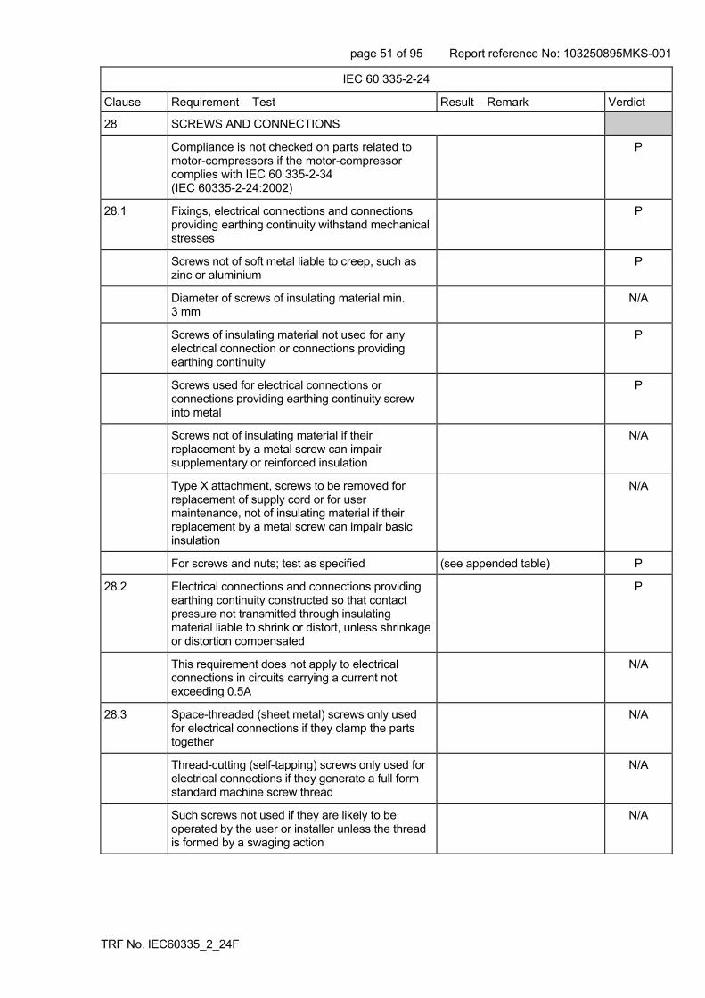
page 51 of 95 Report reference No: 103250895MKS-001
TRF No. IEC60335_2_24F
IEC 60 335-2-24
Clause Requirement – Test Result – Remark Verdict
28 SCREWS AND CONNECTIONS
Compliance is not checked on parts related to motor-compressors if the motor-compressor complies with IEC 60 335-2-34 (IEC 60335-2-24:2002)
P
28.1 Fixings, electrical connections and connections providing earthing continuity withstand mechanical stresses
P
Screws not of soft metal liable to creep, such as zinc or aluminium
P
Diameter of screws of insulating material min. 3 mm
N/A
Screws of insulating material not used for any electrical connection or connections providing earthing continuity
P
Screws used for electrical connections or connections providing earthing continuity screw into metal
P
Screws not of insulating material if their replacement by a metal screw can impair supplementary or reinforced insulation
N/A
Type X attachment, screws to be removed for replacement of supply cord or for user maintenance, not of insulating material if their replacement by a metal screw can impair basic insulation
N/A
For screws and nuts; test as specified (see appended table) P
28.2 Electrical connections and connections providing earthing continuity constructed so that contact pressure not transmitted through insulating material liable to shrink or distort, unless shrinkage or distortion compensated
P
This requirement does not apply to electrical connections in circuits carrying a current not exceeding 0.5A
N/A
28.3 Space-threaded (sheet metal) screws only used for electrical connections if they clamp the parts together
N/A
Thread-cutting (self-tapping) screws only used for electrical connections if they generate a full form standard machine screw thread
N/A
Such screws not used if they are likely to be operated by the user or installer unless the thread is formed by a swaging action
N/A

page 52 of 95 Report reference No: 103250895MKS-001
TRF No. IEC60335_2_24F
IEC 60 335-2-24
Clause Requirement – Test Result – Remark Verdict
Thread-cutting and space-threaded screws may be used in connections providing earthing continuity, provided unnecessary to disturb the connection and at least two screws are used for each connection
N/A
28.4 Screws and nuts that make mechanical connection secured against loosening if they also make electrical connections or connections providing earthing continuity
P
Rivets for electrical connections or connections providing earthing continuity secured against loosening if subjected to torsion
N/A
29 CLEARANCES, CREEPAGE DISTANCES AND SOLID INSULATION
Compliance is not checked on parts related to motor-compressors if the motor-compressor complies with IEC 60 335-2-34 (IEC 60335-2-24:2002)
P
Clearances, creepage distances and solid insulation withstand electrical stress
P
For coatings used on printed circuits boards to protect the microenvironment or to provide basic insulation, annex J applies
N/A
R If coatings are used on printed circuit boards to protect the microenvironment (Type A coating) or to provide basic insulation (Type B coating), Annex J applies. (IEC 60335-1:01 + A1:2004)
N/A
R The microenvironment is pollution degree 1 under Type A coating. (IEC 60335-1:01 + A1:2004)
N/A
R There are no creepage distance or clearance requirements under Type B coating. (IEC 60335-1:01 + A1:2004)
N/A
29.1 Clearances not less than the values specified in table 16, taking into account the rated impulse voltage for the overvoltage categories of table 15
(see appended table) P
The values specified may be smaller for basic insulation and functional insulation if the clearance meets the impulse voltage test of clause 14
N/A
Appliances are in overvoltage category II P
Clearances less than specified in table 16 not allowed for basic insulation of class 0 and class 0I appliances,
P
or if pollution degree 3 is applicable Within fridge freezer compartments
P
Compliance is checked by inspection and measurements as specified
P

page 53 of 95 Report reference No: 103250895MKS-001
TRF No. IEC60335_2_24F
IEC 60 335-2-24
Clause Requirement – Test Result – Remark Verdict
29.1 R Clearances not less than the values specified in table 16, taking into account the rated impulse voltage for the overvoltage categories of table 15, unless for basic insulation and functional insulation they comply with the impulse voltage test of clause 14 (IEC 60335-1:01 + A1:2004)
P
R However, if the construction is affected by wear, distortion, movement of the parts or during assembly, the clearances for rated impulse voltages of 1500V and above are increased by 0,5 mm and the impulse voltage test is not applicable (IEC 60335-1:01 + A1:2004)
N/A
R The impulse voltage test is not applicable when the microenvironment is pollution degree 3 or for basic insulation of class 0 appliances and class 0I appliances (IEC 60335-1:01 + A1:2004)
N/A
R Lacquered conductors of windings considered to be bare conductors (IEC 60335-1:01 + A1:2004)
P
29.1.3 Clearances of reinforced insulation not less than those specified for basic insulation in table 16, but using the next higher step for rated impulse voltage
P
29.1.4 For functional insulation, the values of table 16 are applicable, unless
P
the appliance complies with clause 19 with the functional insulation short-circuited
N/A
Clearances at crossover points of lacquered conductors not measured
N/A
Clearance between surfaces of PTC heating elements may be reduced to 1mm
N/A
Lacquered conductors of windings assumed to be bare conductors, but the clearances specified in table 16 are reduced by 0.5mm for rated impulse voltages of at least 1500V
N/A
R Lacquered conductors of windings considered to be bare conductors (IEC 60335-1:01 + A1:2004)
N/A
R However, clearances at crossover points are not measured (IEC 60335-1:01 + A1:2004)
N/A
29.1.5 Appliances having higher working voltage than rated voltage, the voltage used for determining clearances from table 16 is the sum of the rated impulse voltage and the difference between the peak value of the working voltage and the peak value of the rated voltage
N/A
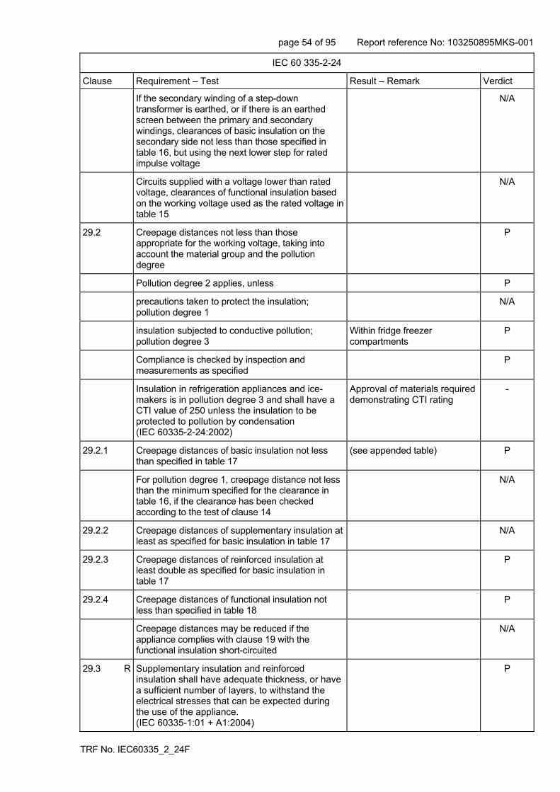
page 54 of 95 Report reference No: 103250895MKS-001
TRF No. IEC60335_2_24F
IEC 60 335-2-24
Clause Requirement – Test Result – Remark Verdict
If the secondary winding of a step-down transformer is earthed, or if there is an earthed screen between the primary and secondary windings, clearances of basic insulation on the secondary side not less than those specified in table 16, but using the next lower step for rated impulse voltage
N/A
Circuits supplied with a voltage lower than rated voltage, clearances of functional insulation based on the working voltage used as the rated voltage in table 15
N/A
29.2 Creepage distances not less than those appropriate for the working voltage, taking into account the material group and the pollution degree
P
Pollution degree 2 applies, unless P
precautions taken to protect the insulation; pollution degree 1
N/A
insulation subjected to conductive pollution; pollution degree 3
Within fridge freezer compartments
P
Compliance is checked by inspection and measurements as specified
P
Insulation in refrigeration appliances and ice-makers is in pollution degree 3 and shall have a CTI value of 250 unless the insulation to be protected to pollution by condensation (IEC 60335-2-24:2002)
Approval of materials required demonstrating CTI rating
-
29.2.1 Creepage distances of basic insulation not less than specified in table 17
(see appended table) P
For pollution degree 1, creepage distance not less than the minimum specified for the clearance in table 16, if the clearance has been checked according to the test of clause 14
N/A
29.2.2 Creepage distances of supplementary insulation at least as specified for basic insulation in table 17
N/A
29.2.3 Creepage distances of reinforced insulation at least double as specified for basic insulation in table 17
P
29.2.4 Creepage distances of functional insulation not less than specified in table 18
P
Creepage distances may be reduced if the appliance complies with clause 19 with the functional insulation short-circuited
N/A
29.3 R Supplementary insulation and reinforced insulation shall have adequate thickness, or have a sufficient number of layers, to withstand the electrical stresses that can be expected during the use of the appliance. (IEC 60335-1:01 + A1:2004)
P
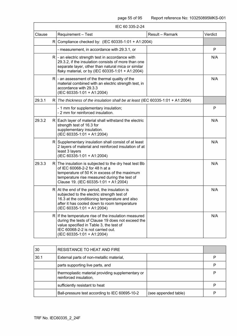
page 55 of 95 Report reference No: 103250895MKS-001
TRF No. IEC60335_2_24F
IEC 60 335-2-24
Clause Requirement – Test Result – Remark Verdict
R Compliance checked by: (IEC 60335-1:01 + A1:2004)
- measurement, in accordance with 29.3.1, or P
R - an electric strength test in accordance with 29.3.2, if the insulation consists of more than one separate layer, other than natural mica or similar flaky material, or by (IEC 60335-1:01 + A1:2004)
N/A
R - an assessment of the thermal quality of the material combined with an electric strength test, in accordance with 29.3.3 (IEC 60335-1:01 + A1:2004)
N/A
29.3.1 R The thickness of the insulation shall be at least (IEC 60335-1:01 + A1:2004)
- 1 mm for supplementary insulation; - 2 mm for reinforced insulation.
P
29.3.2 R Each layer of material shall withstand the electric strength test of 16.3 for supplementary insulation. (IEC 60335-1:01 + A1:2004)
N/A
R Supplementary insulation shall consist of at least 2 layers of material and reinforced insulation of at least 3 layers (IEC 60335-1:01 + A1:2004)
N/A
29.3.3 R The insulation is subjected to the dry heat test Bb of IEC 60068-2-2 for 48 h at a temperature of 50 K in excess of the maximum temperature rise measured during the test of Clause 19. (IEC 60335-1:01 + A1:2004)
N/A
R At the end of the period, the insulation is subjected to the electric strength test of 16.3 at the conditioning temperature and also after it has cooled down to room temperature (IEC 60335-1:01 + A1:2004)
N/A
R If the temperature rise of the insulation measured during the tests of Clause 19 does not exceed the value specified in Table 3, the test of IEC 60068-2-2 is not carried out. (IEC 60335-1:01 + A1:2004)
N/A
30 RESISTANCE TO HEAT AND FIRE
30.1 External parts of non-metallic material, P
parts supporting live parts, and P
thermoplastic material providing supplementary or reinforced insulation,
P
sufficiently resistant to heat P
Ball-pressure test according to IEC 60695-10-2 (see appended table) P

page 56 of 95 Report reference No: 103250895MKS-001
TRF No. IEC60335_2_24F
IEC 60 335-2-24
Clause Requirement – Test Result – Remark Verdict
External parts: at 40 C plus the maximum temperature rise determined during the test of clause 11, or at 75 C, whichever is the higher; temperature (C):
P
Parts supporting live parts: at 40C plus the maximum temperature rise determined during the test of clause 11, or at 125C, whichever is the higher; temperature (C):
P
Parts of thermoplastic material providing supplementary or reinforced insulation, 25C plus the maximum temperature rise determined during clause 19, if higher; temperature (C):
N/A
Relevant external parts of non-metallic material also within the storage compartment parts (IEC 60335-2-24:2002)
P
Accessible parts within the storage compartment 65 °C (IEC 60335-2-24:2002)
P
Following tests do not apply to parts related to the motor-compressor if the motor-compressor complies with IEC 60 335-2-34 (IEC 60335-2-24:2002)
P
30.2 Relevant parts of non-metallic material adequately resistant to ignition and spread of fire
(see appended table) P
Following tests do not apply to parts related to the motor-compressor if the motor-compressor complies with IEC 60 335-2-34 with no ignition (IEC 60335-2-24:2002)
P
30.2.1 Glow-wire test of IEC 60695-2-11 at 550 C, unless
P
the material is classified at least HB40 according to IEC 60695-11-10
N/A
Parts for which the glow-wire test cannot be carried out meet the requirements in ISO9772 for category FH3 material
N/A
Parts for which the glow-wire test cannot be carried out meet the requirements in ISO9772 for category HBF material (IEC 60335-1:01 + A1:2004)
See summary of additional testing in Attachment 4 (and see Intertek Report 103250895LHD-002 for narrative)
P
30.2.2 Not applicable
30.2.3 Appliances operated while unattended, tested as specified in 30.2.3.1 and 30.2.3.2
P
Test not applicable to conditions as specified P
30.2.3.1 Parts of insulating material supporting connections carrying a current exceeding 0.2A during normal operation, and
P

page 57 of 95 Report reference No: 103250895MKS-001
TRF No. IEC60335_2_24F
IEC 60 335-2-24
Clause Requirement – Test Result – Remark Verdict
parts of insulating material within a distance of 3mm,
N/A
having a glow-wire flammability index of at least 850C according to IEC 60695-2-12
P
30.2.3.2 Parts of insulating material supporting current-carrying connections, and
P
parts of insulating material within a distance of 3mm,
N/A
subjected to glow-wire test of IEC 60695-2-11 P
Test not carried out on material having a glow-wire ignition temperature according to IEC 60695-2-13 as specified
P
Glow-wire test of IEC 60695-2-11, the temperature being:
-750C, for connections carrying a current exceeding 0,2A during normal operation
P
-650C, for other connections P
Parts that during the test produce a flame persisting longer than 2 s, tested as specified
N/A
If a flame persists longer than 2 s during the test, parts above the connection, as specified, subjected to the needle-flame test of annex E, unless
N/A
the material is classified as V-0 or V-1 according to IEC 60695-11-10
N/A
30.2.4 Base material of printed circuit boards subjected to needle-flame test of annex E
N/A
Test not applicable to conditions as specified UL 94V-0 P
31 RESISTANCE TO RUSTING
Relevant ferrous parts adequately protected against rusting
P
32 RADIATION, TOXICITY AND SIMILAR HAZARDS
Not applicable
A ANNEX A (INFORMATIVE) ROUTINE TESTS
Description of routine tests to be carried out by the manufacturer
-
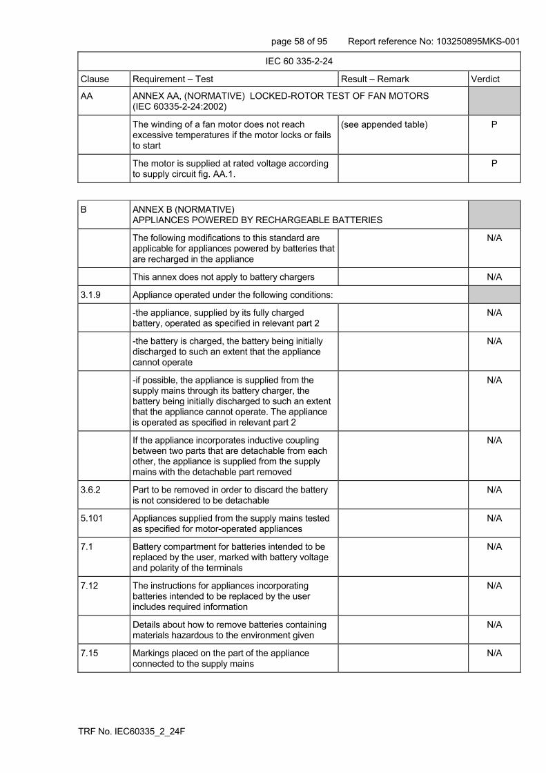
page 58 of 95 Report reference No: 103250895MKS-001
TRF No. IEC60335_2_24F
IEC 60 335-2-24
Clause Requirement – Test Result – Remark Verdict
AA ANNEX AA, (NORMATIVE) LOCKED-ROTOR TEST OF FAN MOTORS (IEC 60335-2-24:2002)
The winding of a fan motor does not reach excessive temperatures if the motor locks or fails to start
(see appended table) P
The motor is supplied at rated voltage according to supply circuit fig. AA.1.
P
B ANNEX B (NORMATIVE) APPLIANCES POWERED BY RECHARGEABLE BATTERIES
The following modifications to this standard are applicable for appliances powered by batteries that are recharged in the appliance
N/A
This annex does not apply to battery chargers N/A
3.1.9 Appliance operated under the following conditions:
-the appliance, supplied by its fully charged battery, operated as specified in relevant part 2
N/A
-the battery is charged, the battery being initially discharged to such an extent that the appliance cannot operate
N/A
-if possible, the appliance is supplied from the supply mains through its battery charger, the battery being initially discharged to such an extent that the appliance cannot operate. The appliance is operated as specified in relevant part 2
N/A
If the appliance incorporates inductive coupling between two parts that are detachable from each other, the appliance is supplied from the supply mains with the detachable part removed
N/A
3.6.2 Part to be removed in order to discard the battery is not considered to be detachable
N/A
5.101 Appliances supplied from the supply mains tested as specified for motor-operated appliances
N/A
7.1 Battery compartment for batteries intended to be replaced by the user, marked with battery voltage and polarity of the terminals
N/A
7.12 The instructions for appliances incorporating batteries intended to be replaced by the user includes required information
N/A
Details about how to remove batteries containing materials hazardous to the environment given
N/A
7.15 Markings placed on the part of the appliance connected to the supply mains
N/A

page 59 of 95 Report reference No: 103250895MKS-001
TRF No. IEC60335_2_24F
IEC 60 335-2-24
Clause Requirement – Test Result – Remark Verdict
8.2 Appliances having batteries that according to the instruction may be replaced by the user need only have basic insulation between live parts and the inner surface of the battery compartment
N/A
If the appliance can be operated without batteries, double or reinforced insulation required
N/A
11.7 The battery is charged for the period described N/A
19.1 Appliances subjected to tests of 19.101, 19.102 and 19.103
N/A
19.101 Appliances supplied at rated voltage for 168 h, the battery being continually charged
N/A
19.102 Short-circuiting of the terminals of the battery, being fully charged, for appliances having batteries that can be removed without the aid of a tool
N/A
19.103 Appliances having batteries replaceable by the user supplied at rated voltage under normal operation with the battery removed or in any position allowed by the construction
N/A
21.101 Appliances having pins for insertion into socket-outlets have adequate mechanical strength, checked according to procedure 2 of IEC 68-2-32
N/A
Part of the appliance incorporating the pins subjected to the free fall test, procedure 2, of IEC 60068-2-32, the number of falls being:
- 100, the mass of part does not exceed 250 g N/A
- 50, the mass of part exceeds 250 g N/A
After the test, the requirements of 8.1, 15.1.1, 16.3 and clause 29 are met
N/A
22.3 Appliances having pins for insertion into socket-outlets tested as fully assembled as possible
N/A
25.13 An additional lining or bushing not required for interconnection cords operating at safety extra-low voltage
N/A
30.2 For parts of the appliance connected to the supply mains during the charging period, 30.2.3 applies
N/A
For other parts, 30.2.2 applies N/A
C ANNEX C (NORMATIVE) AGEING TEST ON MOTORS
Tests, as described, carried out when doubt with regard to the temperature classification of the insulation of a motor winding
N/A
This annex does not apply to motor-compressors(IEC 60335-2-24:2002)
N/A

page 60 of 95 Report reference No: 103250895MKS-001
TRF No. IEC60335_2_24F
IEC 60 335-2-24
Clause Requirement – Test Result – Remark Verdict
CC ANNEX CC (NORMATIVE) NON-SPARKING “N” ELECTRICAL APPARATUS
Where reference is made to IEC 60079-15, the following clauses are applicable as modified below (IEC 60335-2-24:2002/A1:2005)
21 Supplementary requirements for non-sparking luminaires (IEC 60335-2-24:2002/A1:2005)
All of subclauses of Clause 21 are applicable, except 21.2.5.1, 21.2.5.5, 21.2.7, 21.2.8, 21.2.9, 21.2.10, 21.2.11, 21.2.12 and 21.3 (IEC 60335-2-24:2002/A1:2005)
N/A
29 Supplementary requirements for sealed devices or encapsulated devices producing arcs, sparks or hot surfaces (IEC 60335-2-24:2002/A1:2005)
All of the subclauses of Clause 29 are applicable, except 29.1 and 29.8, which are replaced by the following (IEC 60335-2-24:2002/A1:2005)
N/A
29.1 Non metallic materials (IEC 60335-2-24:2002/A1:2005)
Seals are tested using 33.5. However if the device is tested in the appliance, then 33.5.1 and 33.5.1 are not applicable. (IEC 60335-2-24:2002/A1:2005)
N/A
However, after the tests of Clause 19 in IEC 60335-2-24, by inspection, no damage of the encapsulation that could impair the type of protection shall be evident, such as cracks in the resin or exposure of encapsulated parts (IEC 60335-2-24:2002/A1:2005)
N/A
29.8 Type tests (IEC 60335-2-24:2002/A1:2005)
The type tests described in 33.5 shall be performed where relevant (IEC 60335-2-24:2002/A1:2005)
N/A
30 Supplementary requirements for energy-limited apparatus and circuits producing arcs, sparks or hot surfaces (IEC 60335-2-24:2002/A1:2005)
All of the subclauses of Clause 30 are applicable, except 30.5, 30.6 and 30.10
N/A
31 Supplementary requirements for restricted-breathing enclosures protecting apparatus producing arcs, sparks or hot surfaces (IEC 60335-2-24:2002/A1:2005)
All of the subclauses of Clause 31 are applicable, except 31.6 which is replaced by the following
N/A
31.6 Restricted-breathing enclosures shall be type tested, including the cable entry devices (IEC 60335-2-24:2002/A1:2005)
N/A

page 61 of 95 Report reference No: 103250895MKS-001
TRF No. IEC60335_2_24F
IEC 60 335-2-24
Clause Requirement – Test Result – Remark Verdict
D ANNEX D (NORMATIVE) ALTERNATIVE REQUIREMENTS FOR PROTECTED MOTORS
Applicable to protected motors for unattended use, test of 19.7 carried out on a separate sample according to the specification
N/A
This annex does not apply to motor-compressors or condenser fan motors (IEC 60335-2-24:2002)
N/A
This annex is applicable to appliances having motors that incorporate thermal motor protectors (IEC 60335-1:01 + A1:2004).
N/A
The appliance is supplied at rated voltage with the rotor of the motor locked. (IEC 60335-1:01 + A1:2004)
N/A
The duration of the test is as follows: (IEC 60335-1:01 + A1:2004)
- motors having self-resetting thermal motor protectors are operated for 300 cycles or for 72 h, whichever occurs first, unless they are likely to be permanently subjected to the supply voltage in which case the duration is 432 h; (IEC 60335-1:01 + A1:2004)
N/A
- motors having non-self-resetting thermal motor protectors are operated for 30 cycles, the thermal motor protector being reset as soon as possible after each operation, but in not less than 30 s; (IEC 60335-1:01 + A1:2004)
N/A
During the test, temperatures shall not exceed the values specified in 19.7 and the appliance shall comply with 19.13 (IEC 60335-1:01 + A1:2004)
N/A
NOTE This test may be carried out on a separate appliance. (IEC 60335-1:01 + A1:2004)
E ANNEX E (NORMATIVE) NEEDLE-FLAME TEST
Needle-flame test carried out in accordance with IEC 60695-2-2, with the following modifications:
N/A
5 Severities
The duration of application of the test flame is 30 s ± 1 s
N/A
8 Test procedure
8.2 The specimen so arranged that the flame can be applied to a vertical or horizontal edge as shown in the examples of figure 1
N/A
8.4 The first paragraph does not apply N/A
If possible, the flame is applied at least 10 mm from a corner
N/A

page 62 of 95 Report reference No: 103250895MKS-001
TRF No. IEC60335_2_24F
IEC 60 335-2-24
Clause Requirement – Test Result – Remark Verdict
8.5 The test is carried out on one specimen N/A
If the specimen does not withstand the test, the test may be repeated on two further specimens, both withstanding the test
N/A
10 Evaluation of test results
The duration of burning not exceeding 30 s N/A
However, for printed circuit boards, the duration of burning not exceeding 15 s
N/A
F ANNEX F (NORMATIVE) CAPACITORS
Capacitors likely to be permanently subjected to the supply voltage, and used for radio interference suppression or voltage dividing, comply with the following clauses of IEC 60384-14, with the following modifications:
N/A
1.5 Terminology
1.5.3 Class X capacitors tested according to subclass X2
N/A
1.5.4 This subclause is applicable N/A
1.6 Marking
Items a) and b) are applicable N/A
3.4 Approval testing
3.4.3.2 Table II is applicable as described N/A
4.1 Visual examination and check of dimensions
This subclause is applicable NA
4.2 Electrical tests
4.2.1 This subclause is applicable N/A
4.2.5 This subclause is applicable N/A
4.2.5.2 Only table IX is applicable N/A
Values for test A apply N/A
However, for capacitors in heating appliances the values for test B or C apply
N/A
4.12 Damp heat, steady state
This subclause is applicable N/A
Only insulation resistance and voltage proof are checked
N/A
4.13 Impulse voltage
This subclause is applicable N/A

page 63 of 95 Report reference No: 103250895MKS-001
TRF No. IEC60335_2_24F
IEC 60 335-2-24
Clause Requirement – Test Result – Remark Verdict
4.14 Endurance
Subclauses 4.14.1, 4.14.3, 4.14.4 and 4.14.7 applicable
N/A
4.14.7 Only insulation resistance and voltage proof are checked
N/A
Visual examination, no visible damage N/A
4.17 Passive flammability test
This subclause is applicable N/A
4.18 Active flammability test
This subclause is applicable N/A
G ANNEX G (NORMATIVE) SAFETY ISOLATING TRANSFORMERS
The following modifications to this standard are applicable for safety isolating transformers:
N/A
7 Marking and instructions
7.1 Transformers for specific use marked with:
-name, trademark or identification mark of the manufacturer or responsible vendor
N/A
-model or type reference N/A
17 Overload protection of transformers and associated circuits
Fail-safe transformers comply with subclause 15.5 of IEC 61558-1
N/A
22 Construction
Subclauses 19.1 and 19.1.2 of IEC 61558-2-6 are applicable
N/A
29 Clearances, creepage distances and solid insulation
29.1 and 29.2
The distances specified in items 2a, 2c and 3 in table 13 of IEC 61558-1 apply
N/A
H ANNEX H (NORMATIVE) SWITCHES
Switches comply with the following clauses of IEC 61058-1, as modified:
-The tests of IEC 61058-1 carried out under the conditions occurring in the appliance
N/A
-Before being tested, switches are operated 20 times without load
N/A
8 Marking and documentation
Switches are not required to be marked N/A

page 64 of 95 Report reference No: 103250895MKS-001
TRF No. IEC60335_2_24F
IEC 60 335-2-24
Clause Requirement – Test Result – Remark Verdict
However, switches that can be tested separately from the appliance marked with the manufacturer’s name or trade mark and the type reference
N/A
13 Mechanism
The tests may be carried out on a separate sample N/A
15 Insulation resistance and dielectric strength
15.1 Not applicable N/A
15.2 Not applicable N/A
15.3 Applicable for full disconnection and micro-disconnection
N/A
17 Endurance
Compliance is checked on three separate appliances or switches
N/A
For 17.2.4.4, the number of cycles is 10 000, unless otherwise specified in 24.1.3 of the relevant part 2 of IEC 60335
N/A
Switches for operation under no load and which can be operated only by a tool and switches operated by hand that are interlocked so that they cannot be operated under load, are not subjected to the tests
N/A
Subclause 17.2.5.2 is not applicable N/A
Temperature rise of the terminals not more than 30 K above the temperature rise measured in clause 11 of IEC 60335-1
N/A
Subclauses 17.2.2 and 17.2.5.2 are not applicable. The ambient temperature during the test is that occurring in the appliance during the test of Clause 11 in IEC 60335-1, as specified in footnote b of Table 3. (IEC 60335-1:01 + A1:2004)
N/A
20 Clearances, creepage distances, solid insulation and coatings of rigid printed board assemblies
This clause is applicable to clearances and creepage distances for functional insulation, across full disconnection and micro-disconnection, as stated in table 24
N/A
I ANNEX I (NORMATIVE) MOTORS HAVING BASIC INSULATION THAT IS INADEQUATE FOR THE RATED VOLTAGE OF THE APPLIANCE
The following modifications to this standard are applicable for motors having basic insulation that is inadequate for the rated voltage of the appliance:
N/A

page 65 of 95 Report reference No: 103250895MKS-001
TRF No. IEC60335_2_24F
IEC 60 335-2-24
Clause Requirement – Test Result – Remark Verdict
8 Protection against access to live parts
8.1 Metal parts of the motor are considered to be bare live parts
N/A
11 Heating
11.3 Temperature rise of the body of the motor is determined instead of the temperature rise of the windings
N/A
11.8 Temperature rise of the body of the motor, where in contact with insulating material, not exceeding values in table 3 for the relevant insulating material
N/A
16 Leakage current and electric strength
16.3 Insulation between live parts of the motor and its other metal parts not subjected to the test
N/A
19 Abnormal operation
19.1 The tests of 19.7 to 19.9 not carried out N/A
19.101 Appliance operated at rated voltage with each of the following fault conditions:
- short circuit of the terminals of the motor, including any capacitor incorporated in the motor circuit
N/A
- short circuit of each diode of the rectifier N/A
- open circuit of the supply to the motor N/A
- open circuit of any parallel resistor, the motor being in operation
N/A
Only one fault simulated at a time, the tests carried out consecutively
N/A
22 Construction
22.101 For class I appliances incorporating a motor supplied by a rectifier circuit, the d.c. circuit being insulated from accessible parts of the appliance by double or reinforced insulation
N/A
Compliance checked by the tests specified for double and reinforced insulation
N/A
J TME ANNEX J (NORMATIVE) COATED PRINTED CIRCUIT BOARDS
Testing of protective coatings of printed circuit boards carried out in accordance with IEC 60664-3 with the following modifications:
N/A

page 66 of 95 Report reference No: 103250895MKS-001
TRF No. IEC60335_2_24F
IEC 60 335-2-24
Clause Requirement – Test Result – Remark Verdict
K TME ANNEX K (NORMATIVE) OVERVOLTAGE CATEGORIES
The information on overvoltage categories is extracted from IEC 60664-1
P
L ANNEX L (INFORMATIVE) GUIDANCE FOR THE MEASUREMENT OF CLEARANCES AND CREEPAGE DISTANCES
Sequences for the determination of clearances and creepage distances
P
M TME ANNEX M (NORMATIVE) POLLUTION DEGREE
The information on pollution degrees is extracted from IEC 60664-1
P
N ANNEX N (NORMATIVE) PROOF TRACKING TEST
The proof tracking test is carried out in accordance with IEC 60112 with the following modifications:
N/A
5 Test apparatus
5.1 Electrodes
The note does not apply N/A
5.4 Test solutions
Test solution A is used N/A
6 Procedure
6.3 Proof tracking test
Voltage is 100V, 175V, 400V or 600V: N/A
Note 3 of clause 3 applies N/A
The test is carried out on five specimens N/A
In case of doubt, additional test with voltage reduced by 25V, the number of drops increased to 100
N/A
7 Report
The report stating if the PTI value was based on a test using 100 drops with a test voltage of (PTI-25) V
N/A
The proof tracking test is carried out in accordance with IEC 60112 with the following modifications: (IEC 60335-1:01 + A1:2004)
N/A

page 67 of 95 Report reference No: 103250895MKS-001
TRF No. IEC60335_2_24F
IEC 60 335-2-24
Clause Requirement – Test Result – Remark Verdict
Test apparatus (IEC 60335-1:01 + A1:2004)
7.3 Test solutions (IEC 60335-1:01 + A1:2004)
Test solution A is used (IEC 60335-1:01 + A1:2004)
N/A
10 Determination of proof tracking index (PTI) (IEC 60335-1:01 + A1:2004)
10.1 The last paragraph of Clause 3 applies (IEC 60335-1:01 + A1:2004)
N/A
The test is carried out on five specimens (IEC 60335-1:01 + A1:2004)
N/A
In case of doubt, a material is considered to have a PTI of the specified value if it withstands the test at a voltage equal to the proof voltage reduced by 25 V, the number of drops being increased to 100. (IEC 60335-1:01 + A1:2004)
N/A
10.2 The report shall state if the PTI value was based on a test using 100 drops with a test voltage of (PTI-25) V (IEC 60335-1:01 + A1:2004)
N/A
O ANNEX O (INFORMATIVE) SELECTION AND SEQUENCE OF THE TESTS OF CLAUSE 30
Description of tests for determination of resistance to heat and fire
P
P ANNEX P (INFORMATIVE) GUIDANCE FOR THE APPLICATION OF THIS STANDARD TO APPLIANCES USED IN WARM DAMP EQUABLE CLIMATES
The following modifications to this standard are applicable for class 0 appliances and class OI appliances having a rated voltage exceeding 150 V, that are intended to be used in countries having a warm damp equable climate and that are marked WDaE. (IEC 60335-1:01 + A1:2004)
N/A
NOTE Warm damp equable climates are characterized by high humidity and high ambient temperatures with little variation, as specified in IEC 60721-2-1. (IEC 60335-1:01 + A1:2004)
They may also be applied to class I appliances having a rated voltage exceeding 150 V that are intended to be used in countries having a warm damp equable climate and that are marked WDaE, if they are able to be connected to a supply mains that excludes the protective earthing conductor due to deficiencies in the fixed wiring system. (IEC 60335-1:01 + A1:2004)
5.7 The ambient temperature for the tests of Clauses 11 and 13 is 40 +3/0 (IEC 60335-1:01 + A1:2004)
7.1 The appliance marked with the letters WdaE (IEC 60335-1:01 + A1:2004)

page 68 of 95 Report reference No: 103250895MKS-001
TRF No. IEC60335_2_24F
IEC 60 335-2-24
Clause Requirement – Test Result – Remark Verdict
7.12 The instructions shall state that the appliance is to be supplied through a residual current device (RCD) having a rated residual operating current not exceeding 30 mA. (IEC 60335-1:01 + A1:2004)
The instructions shall state the substance of the following: (IEC 60335-1:01 + A1:2004)
11.8 The values of Table 3 are reduced by 15 K (IEC 60335-1:01 + A1:2004)
N/A
13.2 The leakage current for class I appliances not exceeding 0,5 mA (IEC 60335-1:01 + A1:2004)
N/A
15.3 The value of t is 37 C (IEC 60335-1:01 + A1:2004)
N/A
16.2 The leakage current for class I appliances not exceeding 0,5 mA (IEC 60335-1:01 + A1:2004)
N/A
19.13 The leakage current test of 16.2 is applied in addition to the electric strength test of 16.3 (IEC 60335-1:01 + A1:2004)
N/A
R ANNEX R (NORMATIVE) SOFTWARE EVALUATION
Software evaluated in accordance with the following clauses of Annex H of IEC 60730-1, as modified (IEC 60335-1:01 + A1:2004)
H.2 Definitions
Only definitions H.2.16 to H.2.20 applicable (IEC 60335-1:01 + A1:2004)
N/A
H.7 Information
Only footnotes 12) to 18) of Table 7.2, as modified, applicable (IEC 60335-1:01 + A1:2004)
N/A
H.11.12 Controls using software
All of the subclauses of H.11.12 as modified below are applicable, except subclauses H.11.12.6 and H.11.12.6.1 which are not applicable. (IEC 60335-1:01 + A1:2004)
N/A
In the second paragraph, replace "required in items 66 to 72 inclusive" by "referred to in footnotes 12) to 18) inclusive". (IEC 60335-1:01 + A1:2004)
N/A
H.11.12.7 Delete "and identified in table 7.2, requirement 68 (IEC 60335-1:01 + A1:2004)
H.11.12.7.1 For appliances using software class C having a single channel with self-test and monitoring structure, the manufacturer shall provide the measures necessary to address the fault/errors in safety related segments and data indicated in Table H. 11.12.7-1. (IEC 60335-1:01 + A1:2004)
N/A

page 69 of 95 Report reference No: 103250895MKS-001
TRF No. IEC60335_2_24F
IEC 60 335-2-24
Clause Requirement – Test Result – Remark Verdict
H.11.12.8 Software fault/error detection shall occur before compliance with 19.13 of IEC 60335-1 is impaired. (IEC 60335-1:01 + A1:2004)
N/A
H.11.12.8.1RReplace "result in the response declared in table 7.2, requirement 72" by "occur before compliance with 19.13 of IEC 60335-1 is impaired". (IEC 60335-1:01 + A1:2004)
H.11.12.13 The software and safety related hardware under its control shall initialize and terminate before compliance with 19.13 of IEC 60335-1 is impaired. (IEC 60335-1:01 + A1:2004)
N/A

page 70 of 95 Report reference No: 103250895MKS-001
TRF No. IEC60335_2_24F
IEC 60 335-2-58
Remarks
10.1 TABLE: Power input deviation N/A
Input deviation of/at: P rated (W) P measured (W)
dP Required dP Remark
10.2 TABLE: Current deviation F
Current deviation of/at: I rated (A) I measured (A) dI Required dI Remark
220V 0.5 0.650 +30% +20% >+20%
230V 0.5 0.640 +28% +20% >+20%
240V 0.5 0.635 +27% +20% >+20%
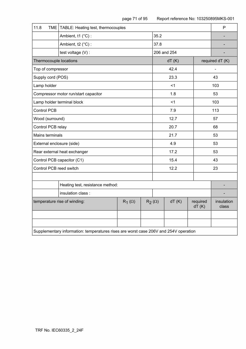
page 71 of 95 Report reference No: 103250895MKS-001
TRF No. IEC60335_2_24F
11.8 TME TABLE: Heating test, thermocouples P
Ambient, t1 (°C) : 35.2 -
Ambient, t2 (°C) : 37.8 -
test voltage (V) : 206 and 254 -
Thermocouple locations dT (K) required dT (K)
Top of compressor 42.4 -
Supply cord (POS) 23.3 43
Lamp holder <1 103
Compressor motor run/start capacitor 1.8 53
Lamp holder terminal block <1 103
Control PCB 7.9 113
Wood (surround) 12.7 57
Control PCB relay 20.7 68
Mains terminals 21.7 53
External enclosure (side) 4.9 53
Rear external heat exchanger 17.2 53
Control PCB capacitor (C1) 15.4 43
Control PCB reed switch 12.2 23
Heating test, resistance method: -
insulation class : -
temperature rise of winding: R1 () R2 () dT (K) required dT (K)
insulation class
Supplementary information: temperatures rises are worst case 206V and 254V operation

page 72 of 95 Report reference No: 103250895MKS-001
TRF No. IEC60335_2_24F
13.2 TME TABLE: Leakage current P
Heating appliances: 1.15 x rated input ................. : -
Motor-operated and combined appliances: 1.06 x rated voltage ............................................... :
254V
Leakage current between Max. allowed I (mA)
accessible metal parts and N <0.1mA 3.5mA
accessible metal parts and L <0.1mA 3.5mA
Other accessible parts and N 0.030mA 0.25mA
Other accessible l parts and L 0.028mA 0.25mA
L1/L2/L3 (Switches a, b and c in ON position) - -
L1 (Switch a is opened) - -
L2 (Switch b is opened) - -
L3 (Switch c is opened) - -
13.3 TME TABLE: Electric strength P
Test voltage applied between: Voltage (V) Breakdown (Yes/No)
live parts and accessible parts over basic insulation 500 -
live parts and accessible parts over basic insulation 1000 No
live parts and accessible parts over supplementary insulation 1750 -
live parts and accessible parts over reinforced insulation 3000 No
14 TABLE: Transient overvoltages N/A
Clearance between: Cl (mm) Required Cl (mm)
Rated impulse voltage (V)
Impulse test voltage (V)
Flashover (Yes/No)

page 73 of 95 Report reference No: 103250895MKS-001
TRF No. IEC60335_2_24F
16.2 TME TABLE: Leakage current P
Single phase appliances: 1.06 x rated voltage ..... : 254V -
Three phase appliances 1.06 x rated voltage divided by 3: ......................................................... :
-
Leakage current between I (mA) Max. allowed I (mA)
Class I Between live parts and metal parts – basic insulation only
0.23 3.5
Class II Between live parts and accessible parts – reinforced insulation
0.03 0.25
Between metal enclosures or covers lined with insulating material and metal foil in contact with the inner surface of the lining.
- -
16.3 TME TABLE: Electric strength P
Test voltage applied between: Voltage (V) Breakdown (Yes/No)
basic insulation 500 -
basic insulation 1250 No
reinforced insulation 3000 No
supplementary insulation 1750 -

page 74 of 95 Report reference No: 103250895MKS-001
TRF No. IEC60335_2_24F
17 TME TABLE: Overload protection of transformers and associated circuits N/A
Temperature rise of part/at: dT (K) Max. dT (K)
Heating test, resistance method: -
temperature rise of winding: R1 () R2 () dT (K) required dT (K)
insulation class
19.7 TABLE: Abnormal operation, locked rotor/moving parts P
Test voltage (V) ........................................................ : 240 -
Ambient, t1 (C) ........................................................ : 23.5 -
Ambient, t2 (C) ........................................................ : 23.7 -
Temperature of winding R1 (Ω) R2 (Ω) (°C) required (C)
insulation class
Fan motor 534.1 623.2 66.5 <90 -
Test as per Annex AA – stabilised within 24 hours

page 75 of 95 Report reference No: 103250895MKS-001
TRF No. IEC60335_2_24F
19.9 TABLE: Abnormal operation, running overload N/A
Test voltage (V) ........................................................ : -
Ambient, t1 (C) ........................................................ : -
Ambient, t2 (C) ........................................................ : -
Temperature of winding R1 (Ω) R2 (Ω) (°C) required (C)
insulation class
19.11 TABLE: Abnormal operation, running overload P
Test voltage (V) ........................................................ : 254 -
Ambient, t1 (C) ........................................................ : 22.5 -
Ambient, t2 (C) ........................................................ : 22.5 -
Temperature of winding R1 (Ω) R2 (Ω) (°C) required (C)
insulation class
- - - - - -
Supplementary information: No temperature rises above normal operation
19.13 TABLE: Abnormal operation, temperature rises P
Thermocouple locations dT (K) Max. dT (K)
Wood (surround) 16.6 150
Mains cable 24.3 150
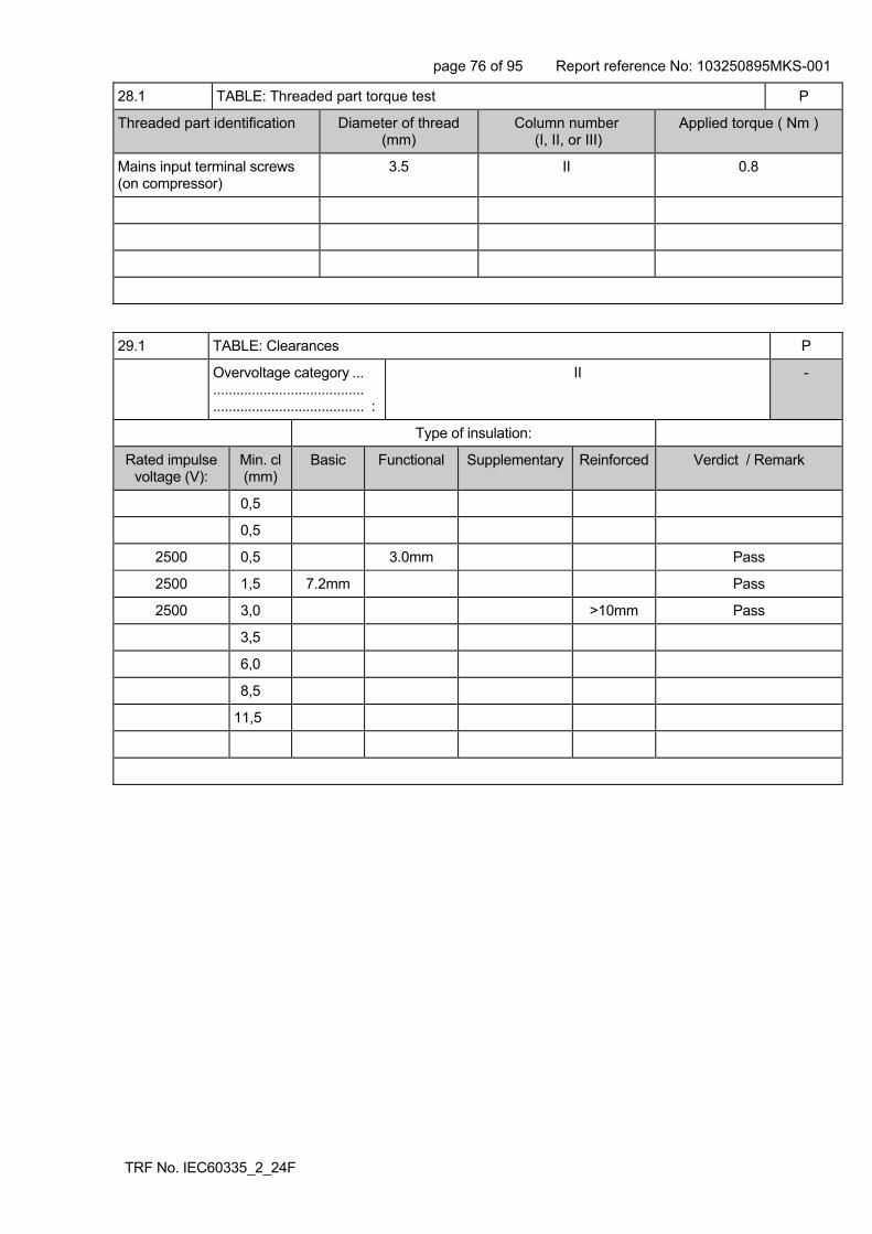
page 76 of 95 Report reference No: 103250895MKS-001
TRF No. IEC60335_2_24F
28.1 TABLE: Threaded part torque test P
Threaded part identification Diameter of thread (mm)
Column number (I, II, or III)
Applied torque ( Nm )
Mains input terminal screws (on compressor)
3.5 II 0.8
29.1 TABLE: Clearances P
Overvoltage category ... ....................................... ....................................... :
II -
Type of insulation:
Rated impulse voltage (V):
Min. cl (mm)
Basic Functional Supplementary Reinforced Verdict / Remark
0,5
0,5
2500 0,5 3.0mm Pass
2500 1,5 7.2mm Pass
2500 3,0 >10mm Pass
3,5
6,0
8,5
11,5

page 77 of 95 Report reference No: 103250895MKS-001
TRF No. IEC60335_2_24F
29.2 TABLE: Creepage distances, basic, supplementary and reinforced insulation P
Working voltage (V)
Creepage distance (mm)
Pollution degree
1 2 3 Type of insulation
Material group Material group (mm)
I II IIIa/IIIb I II Iliad/IIIb B*) S*) R*) Verdict
< 50 0,2 0,6 0,9 1,2 1,5 1,7 1,9
< 50 0,2 0,6 0,9 1,2 1,5 1,7 1,9
< 50 0,4 1,2 1,8 2,4 3,0 3,4 3,8
> 50 and < 125 0,3 0,8 1,1 1,5 1,9 2,1 2,4
> 50 and < 125 0,3 0,8 1,1 1,5 1,9 2,1 2,4
> 50 and < 125 0,6 1,6 2,2 3,0 3,8 4,2 4,8
> 125 and < 250 0,6 1,3 1,8 2,5 3,2 3,6 4,0 >10 Pass
> 125 and < 250 0,6 1,3 1,8 2,5 3,2 3,6 4,0
> 125 and < 250 1,2 2,6 3,6 5,0 6,4 7,2 8,0 >15 Pass
> 250 and < 400 1,0 2,0 2,8 4,0 5,0 5,6 6,3
> 250 and < 400 1,0 2,0 2,8 4,0 5,0 5,6 6,3
> 250 and < 400 2,0 4,0 5,6 8,0 10,0 11,2 12,6
> 400 and < 500 1,3 2,5 3,6 5,0 6,3 7,1 8,0
> 400 and < 500 1,3 2,5 3,6 5,0 6,3 7,1 8,0
> 400 and < 500 2,6 5,0 7,2 10,0 12,6 14,2 16,0
> 500 and < 800 1,8 3,2 4,5 6,3 8,0 9,0 10,0
> 500 and < 800 1,8 3,2 4,5 6,3 8,0 9,0 10,0
> 500 and < 800 3,6 6,4 9,0 12,6 16,0 18,0 20,0
> 800 and < 1000 2,4 4,0 5,6 8,0 10,0 11,0 12,5
> 800 and < 1000 2,4 4,0 5,6 8,0 10,0 11,0 12,5
> 800 and < 1000 4,8 8,0 11,2 16,0 20,0 22,0 25,0
> 1000 and < 1250 3,2 5,0 7,1 10,0 12,5 14,0 16,0
> 1000 and < 1250 3,2 5,0 7,1 10,0 12,5 14,0 16,0
> 1000 and < 1250 6,4 10,0 14,2 20,0 25,0 28,0 32,0
> 1250 and < 1600 4,2 6,3 9,0 12,5 16,0 18,0 20,0
> 1250 and < 1600 4,2 6,3 9,0 12,5 16,0 18,0 20,0
> 1250 and < 1600 8,4 12,6 18,0 25,0 32,0 36,0 40,0
> 1600 and < 2000 5,6 8,0 11,0 16,0 20,0 22,0 25,0
> 1600 and < 2000 5,6 8,0 11,0 16,0 20,0 22,0 25,0
> 1600 and < 2000 11,2 16,0 22,0 32,0 40,0 44,0 50,0
> 2000 and < 2500 7,5 10,0 14,0 20,0 25, 0 28,0 32,0
> 2000 and < 2500 7,5 10,0 14,0 20,0 25, 0 28,0 32,0

page 78 of 95 Report reference No: 103250895MKS-001
TRF No. IEC60335_2_24F
> 2000 and < 2500 15,0 20,0 28,0 40,0 50,0 56,0 64,0
> 2500 and < 3200 10,0 12,5 18,0 25,0 32,0 36,0 40,0
> 2500 and < 3200 10,0 12,5 18,0 25,0 32,0 36,0 40,0
> 2500 and < 3200 20,0 25,0 36,0 50,0 64,0 72,0 80,0
> 3200 and < 4000 12,5 16,0 22,0 32,0 40,0 45,0 50,0
> 3200 and < 4000 12,5 16,0 22,0 32,0 40,0 45,0 50,0
> 3200 and < 4000 25,0 32,0 44,0 64,0 80,0 90,0 100,0
> 4000 and < 5000 16,0 20,0 28,0 40,0 50,0 56,0 63,0
> 4000 and < 5000 16,0 20,0 28,0 40,0 50,0 56,0 63,0
> 4000 and < 5000 32,0 40,0 56,0 80,0 100,0 112,0 126,0
> 5000 and < 6300 20,0 25,0 36,0 50,0 63,0 71,0 80,0
> 5000 and < 6300 20,0 25,0 36,0 50,0 63,0 71,0 80,0
> 5000 and < 6300 40,0 50,0 72,0 100,0 126,0 142,0 160,0
> 6300 and < 8000 25,0 32,0 45,0 63,0 80,0 90,0 100,0
> 6300 and < 8000 25,0 32,0 45,0 63,0 80,0 90,0 100,0
> 6300 and < 8000 50,0 64,0 90,0 126,0 160,0 180,0 200,0
> 8000 and < 10000 32,0 40,0 56,0 80,0 100,0 110,0 125,0
> 8000 and < 10000 32,0 40,0 56,0 80,0 100,0 110,0 125,0
> 8000 and < 10000 64,0 80,0 112,0 160,0 200,0 220,0 250,0
> 10000 and < 12500 40,0 50,0 71,0 100,0 125,0 140,0 160,0
> 10000 and < 12500 40,0 50,0 71,0 100,0 125,0 140,0 160,0
> 10000 and < 12500 80,0 100,0 142,0 200,0 250,0 280,0 320,0
*), B=Basic, S=Supplementary and R=Reinforced

page 79 of 95 Report reference No: 103250895MKS-001
TRF No. IEC60335_2_24F
29.2 TABLE: Creepage distances, functional insulation P
Working voltage (V)
Creepage distance (mm)
Pollution degree
1 2 3
Material group Material group
I II IIIa/IIIb I II IIIa/IIIb Verdict / Remark
< 50 0,2 0,6 0,8 1,1 1,4 1,6 1,8
> 50 and < 125 0,3 0,7 1,0 1,4 1,8 2,0 2,2
> 125 and < 250 0,4 1,0 1,4 2,0 2,5 2,8 3,2 Pass
> 250 and < 400 0,8 1,6 2,2 3,2 4,0 4,5 5,0
> 400 and < 500 1,0 2,0 2,8 4,0 5,0 5,6 6,3
> 500 and < 800 1,8 3,2 4,5 6,3 8,0 9,0 10,0
> 800 and < 1000 2,4 4,0 5,6 8,0 10,0 11,0 12,5
> 1000 and < 1250 3,2 5,0 7,1 10,0 12,5 14,0 16,0
> 1250 and < 1600 4,2 6,3 9,0 12,5 16,0 18,0 20,0
> 1600 and < 2000 5,6 8,0 11,0 16,0 20,0 22,0 25,0
> 2000 and < 2500 7,5 10,0 14,0 20,0 25,0 28,0 32,0
> 2500 and < 3200 10,0 12,5 18,0 25,0 32,0 36,0 40,0
> 3200 and < 4000 12,5 16,0 22,0 32,0 40,0 45,0 50,0
> 4000 and < 5000 16,0 20,0 28,0 40,0 50,0 56,0 63,0
> 5000 and < 6300 20,0 25,0 36,0 50,0 63,0 71,0 80,0
> 6300 and < 8000 25,0 32,0 45,0 63,0 80,0 90,0 100,0
> 8000 and < 10000 32,0 40,0 56,0 80,0 100,0 110,0 125,0
> 10000 and < 12500 40,0 50,0 71,0 100,0 125,0 140,0 160,0
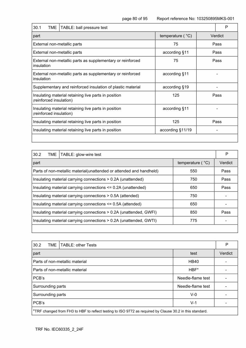
page 80 of 95 Report reference No: 103250895MKS-001
TRF No. IEC60335_2_24F
30.1 TME TABLE: ball pressure test P
part temperature ( °C) Verdict
External non-metallic parts 75 Pass
External non-metallic parts according §11 Pass
External non-metallic parts as supplementary or reinforced insulation
75 Pass
External non-metallic parts as supplementary or reinforced insulation
according §11 -
Supplementary and reinforced insulation of plastic material according §19 -
Insulating material retaining live parts in position (reinforced insulation)
125 Pass
Insulating material retaining live parts in position (reinforced insulation)
according §11 -
Insulating material retaining live parts in position 125 Pass
Insulating material retaining live parts in position according §11/19 -
30.2 TME TABLE: glow-wire test P
part temperature ( °C) Verdict
Parts of non-metallic material(unattended or attended and handheld) 550 Pass
Insulating material carrying connections > 0.2A (unattended) 750 Pass
Insulating material carrying connections <= 0.2A (unattended) 650 Pass
Insulating material carrying connections > 0.5A (attended) 750 -
Insulating material carrying connections <= 0.5A (attended) 650 -
Insulating material carrying connections > 0.2A (unattended, GWFI) 850 Pass
Insulating material carrying connections > 0.2A (unattended, GWTI) 775 -
30.2 TME TABLE: other Tests P
part test Verdict
Parts of non-metallic material HB40 -
Parts of non-metallic material HBF* -
PCB’s Needle-flame test -
Surrounding parts Needle-flame test -
Surrounding parts V-0 -
PCB’s V-1 -
*TRF changed from FH3 to HBF to reflect testing to ISO 9772 as required by Clause 30.2 in this standard.
page 81 of 95 Report reference No: 103250895MKS-001
TRF No. IEC60335_2_24F
This page left intentionally blank

page 82 of 95 Report reference No: 103250895MKS-001
IEC60335_2_24I – ATTACHMENT
Clause Requirement + Test Result - Remark Verdict
TRF No. IEC60335_2_24F
ATTACHMENT TO TEST REPORT IEC 60335-2-24 EUROPEAN GROUP DIFFERENCES AND NATIONAL DIFFERENCES
Part 2: Particular requirements for refrigerating appliances, ice-cream appliances and ice-makers
Differences according to ................ : EN 60335-2-24:2003 + A11:2004 + A1:2005 + A2:2007 + A12:2009EN 60335-1 : 2002+A1 :2004 + A11 :2004 + A2 :2006 + A12 :2006 + A13 : 2008 EN 62233 :08
Attachment Form No. ..................... : EU_GD_IEC60335_2_24I
Attachment Originator ................... : Electrosuisse
Master Attachment ......................... : Dated 2010-04
Copyright © 2010 IEC System for Conformity Testing and Certification of Electrical Equipment (IECEE), Geneva, Switzerland. All rights reserved.
CENELEC COMMON MODIFICATIONS (EN)
6 CLASSIFICATION P
6.1 Protection against electric shock: Class I, II, III
P
7 MARKING AND INSTRUCTIONS
7.1 A Marking of rated voltage or rated voltage range, for appliances intended to be connected to the supply mains, shall cover:
- 230 V for single-phase appliances P
- 400 V for multi-phase appliances N/A
7.15 The height of the letters used for the marking of the type of flammable insulation blowing gas shall be at least 40 mm. (A12:2009)
P
24 COMPONENTS
24.1.7 R If the remote operation of the appliance is via a telecommunication network, the relevant standard for the telecommunication interface circuitry in the appliance are EN 41003 and EN 60960-1:2006, Subclause 6.3.(A13:2008)
N/A
24.5 The second paragraph of the requirement is not applicable (EN 60335-1:2002 + A11:2004)
N/A
25 SUPPLY CONNECTION AND EXTERNAL FLEXIBLE CORDS
25.6 A Supply cords of single-phase portable appliances having a rated current not exceeding 16 A shall be fitted with a plug complying with the standard sheets of IEC 60083:1975:
- for class I appliances standard sheet C2b, C3b, or C4
P
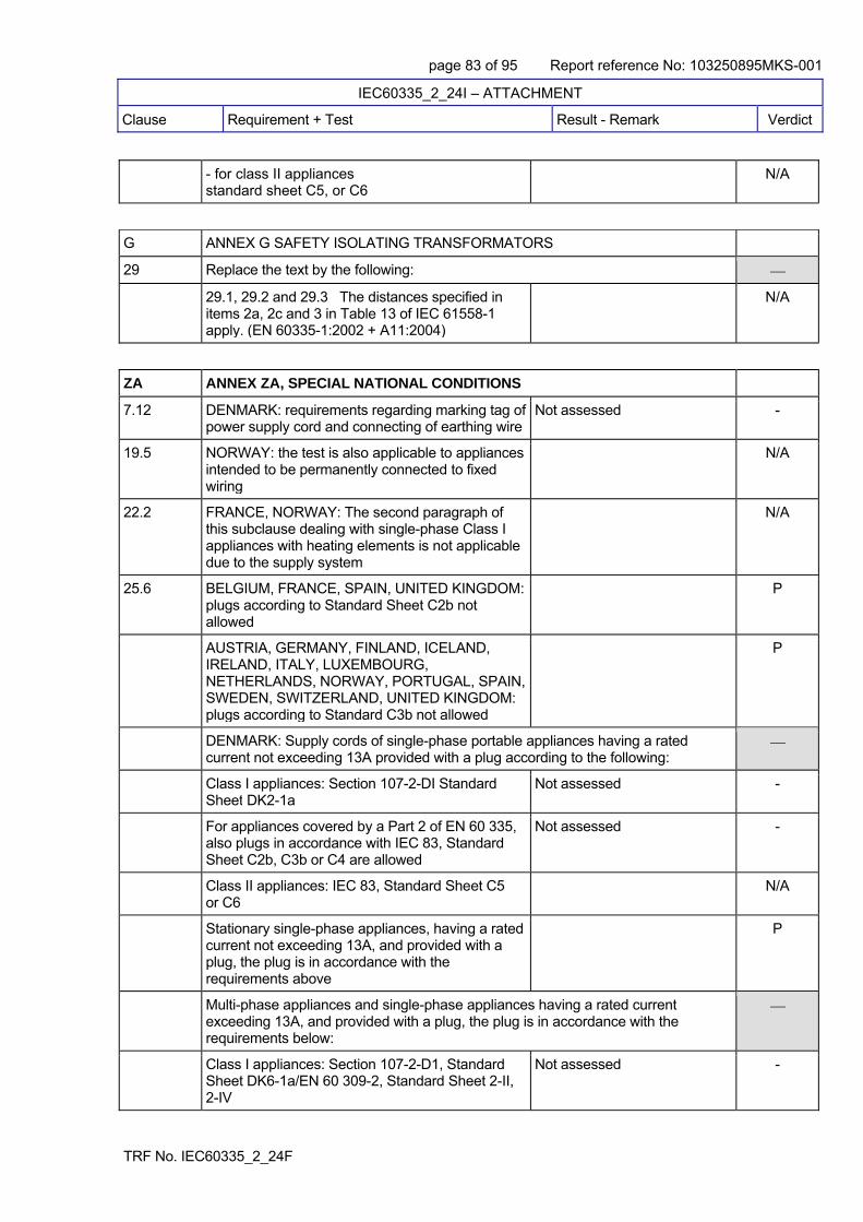
page 83 of 95 Report reference No: 103250895MKS-001
IEC60335_2_24I – ATTACHMENT
Clause Requirement + Test Result - Remark Verdict
TRF No. IEC60335_2_24F
- for class II appliances standard sheet C5, or C6
N/A
G ANNEX G SAFETY ISOLATING TRANSFORMATORS
29 Replace the text by the following:
29.1, 29.2 and 29.3 The distances specified in items 2a, 2c and 3 in Table 13 of IEC 61558-1 apply. (EN 60335-1:2002 + A11:2004)
N/A
ZA ANNEX ZA, SPECIAL NATIONAL CONDITIONS
7.12 DENMARK: requirements regarding marking tag of power supply cord and connecting of earthing wire
Not assessed -
19.5 NORWAY: the test is also applicable to appliances intended to be permanently connected to fixed wiring
N/A
22.2 FRANCE, NORWAY: The second paragraph of this subclause dealing with single-phase Class I appliances with heating elements is not applicable due to the supply system
N/A
25.6 BELGIUM, FRANCE, SPAIN, UNITED KINGDOM: plugs according to Standard Sheet C2b not allowed
P
AUSTRIA, GERMANY, FINLAND, ICELAND, IRELAND, ITALY, LUXEMBOURG, NETHERLANDS, NORWAY, PORTUGAL, SPAIN, SWEDEN, SWITZERLAND, UNITED KINGDOM: plugs according to Standard C3b not allowed
P
DENMARK: Supply cords of single-phase portable appliances having a rated current not exceeding 13A provided with a plug according to the following:
Class I appliances: Section 107-2-DI Standard Sheet DK2-1a
Not assessed -
For appliances covered by a Part 2 of EN 60 335, also plugs in accordance with IEC 83, Standard Sheet C2b, C3b or C4 are allowed
Not assessed -
Class II appliances: IEC 83, Standard Sheet C5 or C6
N/A
Stationary single-phase appliances, having a rated current not exceeding 13A, and provided with a plug, the plug is in accordance with the requirements above
P
Multi-phase appliances and single-phase appliances having a rated current exceeding 13A, and provided with a plug, the plug is in accordance with the requirements below:
Class I appliances: Section 107-2-D1, Standard Sheet DK6-1a/EN 60 309-2, Standard Sheet 2-II, 2-IV
Not assessed -

page 84 of 95 Report reference No: 103250895MKS-001
IEC60335_2_24I – ATTACHMENT
Clause Requirement + Test Result - Remark Verdict
TRF No. IEC60335_2_24F
Class II appliances: Section 107-2-D1, Standard Sheet DK6-1a/2-II, 2-IV
Not assessed -
IRELAND: plug is in accordance with Standard Sheets B2 and C5 are allowed
Not assessed -
ITALY: Only plugs listed in CENENLEC Report ROBT-005:2001 are allowed
Not assessed -
SPAIN: For appliances for household use, only the following plugs are allowed:
- according to UNE 20315: ESC 10-1b, C2b, C4, C6 or ESB 25-5b
Not assessed -
- according to UNE-EN 50075 Not assessed -
SWITZERLAND: supply cords of portable household and similar electrical appliances, rated current not exceeding 10 A, provided with a plug complying with SEV 1011 or IEC 884-1 and one of the following dimension sheets:
SEV 6532-2:1991 plug type 15 3P+N+PE 250/400 V, 10 A
Not assessed -
SEV 6532-2:1991 plug type 11 L+N 250 V, 10 A Not assessed -
SEV 6532-2:1991 plug type 12 L+N+PE 250 V, 10 A
Not assessed -
25.8 IRELAND, UNITED KINGDOM: replacement of figures (rated current/cross-sectional area) in the table
P
29 CLEARANCES, CREEPAGE DISTANCES AND SOLID INSULATION
29.3 R - an assessment of the thermal quality of the material combined with an electric strength test, in accordance with 29.3.3 and, for accessible reinforced insulation consisting of a single layer, measurement in accordance with 29.3.Z1 (EN 60335-1/A12:2006)
N/A
ZAA ANNEX ZAA, informative
Relevance of the Directive for pressure equipment(EN 60335-2-24:2003 + A11:2004)
N/A
ZB ANNEX ZB, A-DEVIATIONS
4 SWITZERLAND: information about batteries N/A
7.1 ITALY: the voltage is 220 V/380 V N/A
25.6 IRELAND: regulations concerning plugs to be fitted to domestic appliances
N/A

page 85 of 95 Report reference No: 103250895MKS-001
IEC60335_2_24I – ATTACHMENT
Clause Requirement + Test Result - Remark Verdict
TRF No. IEC60335_2_24F
UNITED KINGDOM: regulations concerning plugs to be fitted to domestic appliances
P
29.3 The provisions of the third dashed item are not applicable for appliances, where the insulation is accessible (EN 60335-1:2002/A1:2004)
N/A
Appropriate additional measures, such as a multi-layered insulation or adequate thickness, shall be taken if used for accessible insulation to ensure that the appliance will not become hazardous in case of the presence of one failure (e.g. a hole in the layer) (EN 60335-1:2002/A1:2004)
N/A
ZC ANNEX ZC, NORMATIVE REFERENCES TO INTERNATIONAL PUBLICATIONS WITH THEIR CORRESPONDING EUROPEAN PUBLICATIONS
The annex contains a list of standards which are referred to, and thus become part of, this standard(A1:2005)
P
ZD ANNEX ZD, informative
IEC and CENELEC code designations for flexible cords
P
29.3.Z1 Minimum thickness of single layers used for accessible reinforce insulation mm (EN A12/2006)
Rated voltage V Overvoltage cat I Overvoltage cat II Overvoltage cat. III Verdict
< 50 0.01 0.04 0.1 N/A
50 ≤ 150 0.1 0.3 0.6 N/A
150 ≤ 300 0.3 0.6 1.2 N/A
EMF ANNEX EMF, ELECTROMAGNETIC FIELDS
The Tested product also complies to the requirements of EN 62233:08
Limit 100% Measured max.: 0.13% P

page 86 of 95 Report reference No: 103250895MKS-001
TRF No. IEC60335_2_24F
Attachment 1 - Photographs
Front view of fridge freezer (sample ident No 9)
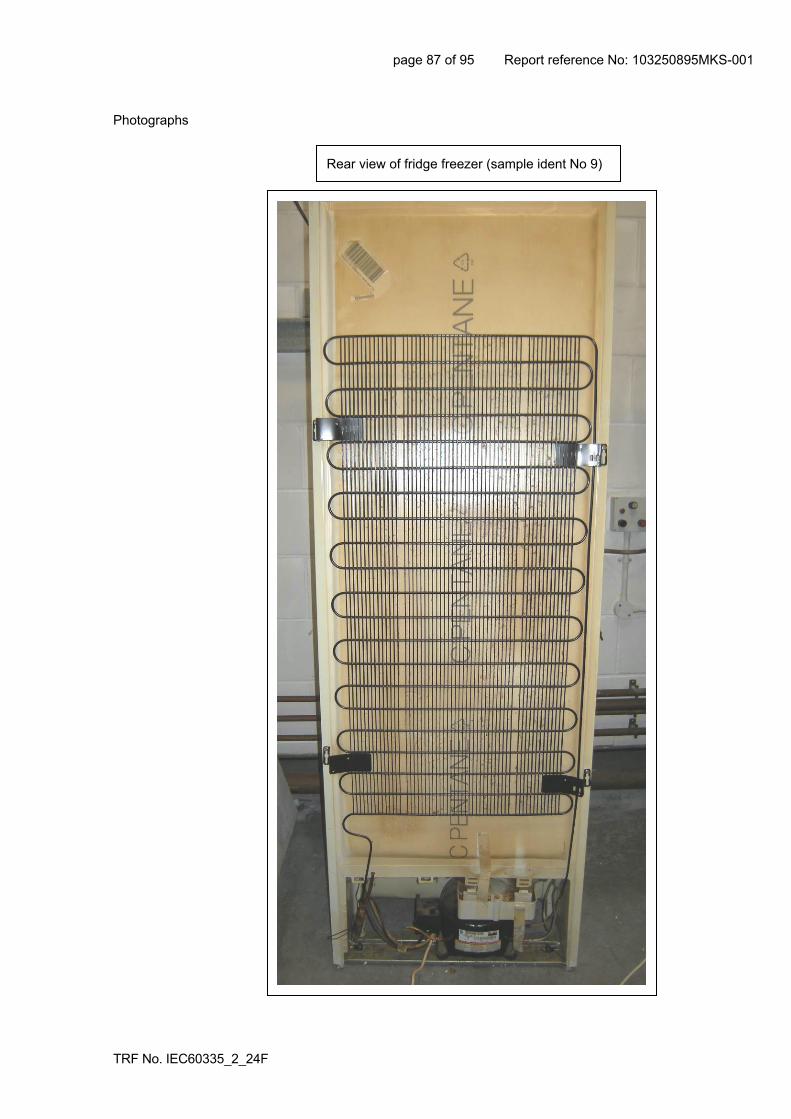
page 87 of 95 Report reference No: 103250895MKS-001
TRF No. IEC60335_2_24F
Photographs
Rear view of fridge freezer (sample ident No 9)

page 88 of 95 Report reference No: 103250895MKS-001
TRF No. IEC60335_2_24F
Photographs
Rear lower section, showing water tray (defrost) above the compressor
Compressor marking label

page 89 of 95 Report reference No: 103250895MKS-001
TRF No. IEC60335_2_24F
Photographs
Ducati compressor motor capacitor
Control PCB

page 90 of 95 Report reference No: 103250895MKS-001
TRF No. IEC60335_2_24F
Photographs
View of insulation foam visible at roof of compressor cavity
View of insulation foam visible at roof of compressor cavity

page 91 of 95 Report reference No: 103250895MKS-001
TRF No. IEC60335_2_24F
Attachment 2 - Machine Configuration – Assigned No: 2
Serial No: 811054572
Manufacture Date: 08/11/05 (YY/MM/DD)
Mains Plug: Manufacturer MC, model S200 (moulded plug), rating 250V~ 13A, Approval ASTA Ref 744, BS 1363/A.
Mains plug fuse: Manufacturer Atlas, rating 13A, Approval ASTA/BSI, BS1362.
Mains power cord: Manufacturer Matcavi, type H05VV-F, IEC 60227-5.
Compressor: Manufacturer Embraco, model EMY66CLP, rated 220-240V~ 50Hz marked 23/oct/08, Approval VDE, PCT.
Compressor Capacitor: manufacturer Ducati, model 16.87.27, rating 4µF 450V~, Approval IMQ/VDE P2 EN 60252-1.
Other
Colour: White
Door Hinge: RHS
Overall power/current rating: 0.5A (220-240V~)
Heater rating: 180W
Classification: SN, N, ST
Refrigerant R600a mass: 0.04kg

page 92 of 95 Report reference No: 103250895MKS-001
TRF No. IEC60335_2_24F
Attachment 3 - Gap analysis
Note that this gap analysis has identified only those changes to the standard applicable to the fridge/freezer tested, other differences have been ignored.
The gap analysis has been split first by standard (EN 60335-2-24 and EN 60335-1) and then by clause.
Comments have been given, briefly explaining the rational for the requirements; no assessment has been made as to whether the product meets the requirements.
EN 60335-2-24:2003+A2:2007 Vs EN 60335-2-24:2010
Clause 7 Marking and instructions
Clause 7.12 Instructions shall state the substance of the following:
Do not store explosive substances such as aerosol cans with a flammable propellant in this appliance.
Clause 7.12.1 Instructions shall include the method for replacing illuminating lamps.
Comment: above requirements are self-explanatory
Clause 22 Construction
Clause 22.111 In compression-type appliances which use flammable refrigerant in their cooling system, all possible inadvertent contact points between uncoated aluminium and copper pipes or similar dissimilar metals shall be prevented from galvanic coupling by positive means such as the use of insulated sleeving or spacers.
Comment: requirement avoids galvanic corrosion that could compromise the integrity of the sealed flammable refrigerant system.
Clause 22.116 Accessible glass panels with an area having any two orthogonal dimensions exceeding 75mm shall be either made from glass that shatters into small pieces when broken or be made from glass that has enhanced mechanical strength.
Comment: requirement reduces the likelihood that a broken glass will present an injury/cut hazard.

page 93 of 95 Report reference No: 103250895MKS-001
TRF No. IEC60335_2_24F
Gap analysis continued
EN 60335-1:2002+A2:2006 Vs EN 60335-1:2012+A11:2014
Clause 3 Definitions
Clause 3.Z.1 – Added definitions of children, young children, older children, vulnerable people etc.
Clause 7 Marking and instructions
Clause 7.12 Instructions shall include the substance of the following:
Required instructions relate to the permitted use, cleaning and maintenance by persons in clause 3.Z.1.
Clause 7.12.Z1 The specific instructions related to the safe operation of this appliance (as given in 7.12 of this standard) shall be collated together in the front section of the user instructions. The height of the characters, measured on the capital letters, shall be at least 3 mm. These instructions shall also be available in an alternative format, e.g. on a website.
Comment: above requirements are self-explanatory
Clause 8 Protection against access to live parts
Clause 8.1.1 Adds the use of probe 18 of IEC 61032 in determining accessible live parts.
Note: This probe is intended to simulate access to hazards parts by children between the ages of 3 and 14 years.
Comment: requirement included to protect children from accessing live parts.

page 94 of 95 Report reference No: 103250895MKS-001
TRF No. IEC60335_2_24F
Gap analysis continued
Clause 24 Components Clause 24.8 was added in the 2012 edition of EN 60335-1. Clause 24.8 Motor running capacitors in appliances for which 30.2.3 is applicable and that are permanently connected in series with a motor winding shall not cause a hazard in the event of a capacitor failure. The requirement is considered to be met by one or more of the following conditions: – the capacitors are of class of safety protection P2 according to IEC 60252-1; – the capacitors are housed within a metallic or ceramic enclosure that will prevent the emission of flame or molten material resulting from failure of the capacitor; NOTE The enclosure may have an entry or exit hole for the wiring connecting the capacitor to the motor. – the distance of separation of the outer surface of the capacitor to adjacent non-metallic parts exceeds 50 mm; – adjacent non-metallic parts within 50 mm of the outer surface of the capacitor withstand the needle-flame test of Annex E; – adjacent non-metallic parts within 50 mm of the outer surface of the capacitor are classified as at least V-1 according to IEC 60695-11-10, provided that the test sample used for the classification was no thicker than the relevant part of the appliance.
Comment: requirement reduces the likelihood that the motor capacitor will present a fire source in the event of the capacitor failure.
Clause 32 Radiation, toxicity and similar hazards
Clause 32 EMF checked according to EN 50366 or EN 62233.
Comment: requirement ensures that the appliance does not generate electro-magnetic fields that are harmful to health.
It should be noted that the Official Journal of the EU (EUOJ) still lists ALL previous editions of EN 60335-1. This implies that any of these editions may be used as a Presumption of Conformity with the Low Voltage Directive when used in conjunction with the applicable Part 2 standard. This conflicts with the current edition of the standard EN 60335-1:2012 + A11:2014 which states that the 2012 edition was withdrawn from the 21st November 2014.

page 95 of 95 Report reference No: 103250895MKS-001
TRF No. IEC60335_2_24F
Attachment 4 - Additional Testing – Clause 30.2.1 - Opinion
Whilst the gap analysis covering the later edition of these standards shows that Clause 30.2 remained unchanged, it is hard to ignore the nature of the subject incident, the construction of FF175B, reports from the London Fire Brigade on capacitor fires and the updates to capacitor construction (P0, P1, P2 and S0, S1, S2) that have occurred since the date of manufacture of the sample under test (2008).
Given the construction of the FF175B includes several large holes in the surface above the compressor and the run capacitor, Intertek conducted additional material testing, in agreement with BEIS, on the insulation foam in isolation for exposed material.
Clause 30.2 requires that ‘…tests are carried out on non-metallic materials that have been removed from the appliance.’
Furthermore, Clause 30.2.1 states
A full narrative covering this additional testing is included in 103250895LHD-002
Despite the findings noted, it remains Intertek’s view that the Hotpoint FF175B represents no greater risk than other, similar refrigeration appliances placed on the market over the same period.
In 2006, when this model was first placed on the market, there was insufficient historical data that would indicate that run or start capacitors represented a potential ignition source and therefore any exposed foam within the compressor cavity would very likely NOT have been assessed by test laboratories, including Intertek.
Flammability tests of the soft foamy materials used in the appliance construction (the bulk of the thermal insulation material at the back, top and sides of the appliance, and polystyrene material behind rear panel within the fridge compartment) to the requirements of ISO 9772, were conducted by ITIR Innovation Limited. The results of this testing are contained within ITIR Innovation Limited’s report L17-419 dated 29 August 2017 (report held on file).
End of report