Embed Size (px)
Citation preview

TEST REPORT
BS 1363
Rewirable and non-rewirable 13 A fused plugs
Part 1: 2016 Incorporating Amendment 1:2018
Report No. ........................................ : 4376968.50
Tested by (printed name and signature) ......................................... : A. Han (Engineer)
……………………
Approved by (printed name and signature) ......................................... : J. Peng (Reviewer)
……………………
Page of report .................................. : 45 pages
Date of issue .................................... : 2021-08-23
This report is based on a blank test report that was prepared by DEKRA.
Testing Laboratory Name ................ : DEKRA Testing and Certification (Shanghai) Ltd., Guangzhou branch
Address ........................................... : No.3, Qiyun Road, Huangpu District, Guangzhou, Guangdong, China
Testing location ............................... : As above
Applicant's Name ............................. : ShenZhen Konua Technology Industry Co., Ltd.
Address ........................................... : 12A10 Information Building Baoyunda Logistics Center, Qianjin Second Road, Xixiang Avenue, Xixiang Street, Baoan Area, 518101, Shenzhen City, China
Test specification
Standard ........................................... : BS 1363-1: 2016+A1: 2018
Test procedure ................................ : Type test
Procedure deviation ......................... : N/A
Non-standard test method ............... : N/A
Test Report Form
Test Report Form No. ....................... : BS 1363_1D
TRF originator . ................................. : DEKRA
Master TRF ...................................... : dated 18-08
Test item description ....................... : Fused plug
Type of accessory ............................ : Fused plug
Trade mark ...................................... : KONUA
Manufacturer…………………………..: Xinfeng Konua Electronics Co., Ltd.
Chengxin Road, Xinfeng Industrial Park, Xinfeng County, 341600, Ganzhou City, Jiangxi Province, China
Model and/or type reference ........... : KP-26

Page 2 of 45 Report No.: 4376968.50
TRF No.: BS 1363_1D TRF originator: DEKRA
Test item particulars
Rated current (A) ............................................ : 3A, 6A, 10A, 13A
Rated voltage (V)............................................ : 250V~
Kind of use ...................................................... : Rough use
Provision for earthing...................................... : With earthing contact / with ISOD (Insulated Shutter Opening Device)
Method of connecting the cable ..................... : Non-rewirable
Type of cable .................................................. : with ISOD:
H03VV-F 2X0,5/0,75mm2 H03VVH2-F 2X0,5/0,75mm2 H05VVH2-F 2X0,75/1,0mm2 H05VV-F 2X0,75/1,0/1,5mm2 H05RR-F 2X0,75/1,0/1,5mm2 H05RN-F 2X0,75/1,0mm2 with earthing pin: H03VV-F 3X0,5/0,75mm2 H05VV-F 3X0,75/1,0/1,5mm2 H05RR-F 3X0,75/1,0/1,5mm2 H05RN-F 3X0,75/1,0mm2
Nominal cross-sectional areas (mm2) ............ : See above
Type of terminals ............................................ : N/A
Type of connections ....................................... : Crimped
Test case verdicts
Test case does not apply to the test object ... : N/A
Test item does meet the requirement ............ : P(ass)
Test item does not meet the requirement ..... : F(ail)
Testing
Date of receipt of test item ............................ : 2021-06-28
Date(s) of performance of test ....................... : 2021-07-08 to 2021-07-24
National differences:
N/A.
General remarks
This report shall not be reproduced except in full without the written approval of the testing laboratory.
The test results presented in this report relate only to the item(s) tested.
”(see remark #)" refers to a remark appended to the report.
"(see Annex #)" refers to an annex appended to the report.
Throughout this report a comma is used as the decimal separator.
The measurement result is considered in conformance with the requirement if it is within the prescribed limit, It is not necessary to calculate the uncertainty associated with the measurement result.
This report is not used for social proof in China market.
Full type testing.

Page 3 of 45 Report No.: 4376968.50
TRF No.: BS 1363_1D TRF originator: DEKRA
Copy of marking plate, for example:
On the engagement surface:
On external accessible surface:
FUSED
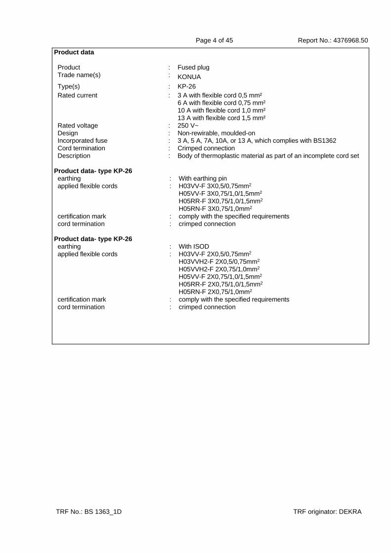
Page 4 of 45 Report No.: 4376968.50
TRF No.: BS 1363_1D TRF originator: DEKRA
Product data Product : Fused plug Trade name(s) : KONUA
Type(s) : KP-26
Rated current : 3 A with flexible cord 0,5 mm² 6 A with flexible cord 0,75 mm² 10 A with flexible cord 1,0 mm² 13 A with flexible cord 1,5 mm²
Rated voltage : 250 V~ Design : Non-rewirable, moulded-on Incorporated fuse : 3 A, 5 A, 7A, 10A, or 13 A, which complies with BS1362 Cord termination : Crimped connection Description : Body of thermoplastic material as part of an incomplete cord set
Product data- type KP-26 earthing : With earthing pin applied flexible cords : H03VV-F 3X0,5/0,75mm2
H05VV-F 3X0,75/1,0/1,5mm2 H05RR-F 3X0,75/1,0/1,5mm2 H05RN-F 3X0,75/1,0mm2
certification mark : comply with the specified requirements cord termination : crimped connection
Product data- type KP-26 earthing : With ISOD applied flexible cords : H03VV-F 2X0,5/0,75mm2
H03VVH2-F 2X0,5/0,75mm2 H05VVH2-F 2X0,75/1,0mm2 H05VV-F 2X0,75/1,0/1,5mm2 H05RR-F 2X0,75/1,0/1,5mm2 H05RN-F 2X0,75/1,0mm2
certification mark : comply with the specified requirements cord termination : crimped connection

Page 5 of 45 Report No.: 4376968.50
TRF No.: BS 1363_1D TRF originator: DEKRA
List of components
Component Manufacturer Type/ technical data Approval mark 1)
Fuse link Dongguan Ubill Electrical Co., Ltd.
UBL8808 3 A, 5A, 7A, 10A, or 13 A
ASTA 1204
Flexible cables KONUA H03VV-F 3G0,5/0,75 mm2 H03VV-F 2X0,5/0,75mm2 H03VVH2-F 2X0,5/0,75mm2
KEMA KEUR 31-120749
Flexible cables KONUA H05VV-F 3G0,75/1,0/1,5 mm2 H05VVH2-F 2X0,75/1,0mm2 H05VV-F 2X0,75/1,0/1,5mm2
KEMA KEUR 31-120805
Flexible cables Huizhou Mainland Electric Wire & Cable Co., Ltd.
H05RR-F 3X0,75/1,0/1,5mm2 H05RN-F 3X0,75/1,0mm2
H05RR-F 2X0,75/1,0/1,5mm2 H05RN-F 2X0,75/1,0mm2
VDE 40026038
Insert with earthing pin
Dongguan Zhenghao Electrical Co., Ltd.
ZH888 *
Insert with ISOD Dongguan Zhenghao Electrical Co., Ltd.
ZH889 *
L, N, E pins SUZHOU SHENGFU TECH METAL MATERIALS CO LTD
H59-3, Brass, Cu>57%, Nickel plated
*
Current carrying plate, fuse clip
SUZHOU SHENGFU TECH METAL MATERIALS CO LTD
H59-3, Brass, Cu>63% *
Insulating material of inert
NANTONG ORIENT PLASTICS CO LTD
3080 G30, PBT UL E332375
Material of insert cover
Dongguan Zhenghao Electrical Co., Ltd.
5003(+), PP
*
Material of ISOD NANTONG ORIENT PLASTICS CO LTD
PA6+Fe *
Material of fuse cover
Dongguan Zhenghao Electrical Co., Ltd.
PA6 *
Moulding material
GuangDong QiLong Technology Co., Ltd.
QL80A, PVC, all colours UL E351522
1) * indicates a component tested as part of the product(s)
Factory location:
Xinfeng Konua Electronics Co., Ltd.
Chengxin Road, Xinfeng Industrial Park, Xinfeng County, 341600, Ganzhou City, Jiangxi Province, China

Page 6 of 45 Report No.: 4376968.50
BS 1363 : Part 1 : 2016 Incorporating Amendment 1:2018
Cl. Requirement – Test Result Verdict
TRF No.: BS 1363_1D TRF originator: DEKRA
Inspection, measurement, gauging and manipulation P
Sequence no. 1 P
5 General conditions for type testing P
5.1 All tests shall be type tests P
Samples tested as delivered P
Samples tested at ambient temperature of 20°C ± 5 °C and after being conditioned at normal laboratory temperature and humidity levels for at least four days
P
5.2 All inspections and tests, of any one classification (see clause 6), shall be carried out as specified in the clauses listed in table 1 on the number of samples in the samples and in the order given.
P
5.3. Gauges in accordance with fig. 5 shall be considered to conform to the dimensional requirements of the results of the measured values are within the specified dimensions and the uncertainty of measurement at not less than 95 confidence level does not exceed ± 0,005 mm
P
6 Classification P
rewirable plug N/A
non-rewirable plug P
Switched plug N/A
Unswitched plug P
plug for normal use N/A
plug for rough use P
Plug for electric vehicle (EV) charging N/A
fitted with screw terminals N/A
fitted with screwless terminals N/A
non-rewirable plugs for class II: fitted with un-terminated brass earth pin or ISOD (Insulated Shutter Opening Device)
fitted with ISOD P
7 Marking and labelling P
- manufacturer’s or responsible vendor’s name...... : KONUA P
- the number of the BS standard (BS 1363) BS1363 P
- rough use plugs the number of this standard shall be followed by /A
/A P

Page 7 of 45 Report No.: 4376968.50
BS 1363 : Part 1 : 2016 Incorporating Amendment 1:2018
Cl. Requirement – Test Result Verdict
TRF No.: BS 1363_1D TRF originator: DEKRA
- rewirable plugs; terminals intended for the connection of the various conductors shall be identified by the symbols given in 7.5
N/A
- the word FUSE or FUSED or the symbol (as given in 7.5) on the external accessible surface of the plug
FUSED P
- rewirable plugs shall be marked with rated current on the engagement face
N/A
- non-rewirable plugs shall be marked with the fuse link fitted (A) ............................................................ :
3 A, 5 A, 7 A, 10 A, or 13 A P
- rated current fuse shall not exceed the value given in table 2 for the appropriate size of the flexible cord
P
- plugs with screwless terminals marked with length of conductor insulation to be removed before fitting the conductor in the terminal
N/A
- for plugs for electric vehicle charging, the number of this British Standard shall be followed by “/EV”.
N/A
7.1.1 Marking durable and easily legible. Test: 15 s with water and 15 s with aliphatic solvent hexane with a content of aromatics of maximum 0,1 % by volume, a kauri-butanol value of 29, an initial boiling point of approximately 69 °C, and relative density of approximately 0,68
P
Markings produced by an engraving or moulding process shall be deemed to conform without test
Moulded P
7.2 rewirable plugs shall have a removable tag or label indicating the rating of the fuse link fitted, e.g. “fitted with 3 ampere fuse”
N/A
7.2.1 Conformity shall be checked by inspection N/A
7.3 plugs fitted with flexible cord not supplied directly to a manufacturer for incorporation in other equipment, the free end of such an assembly shall have label showing the following information
N/A
- the statement: “The flexible cord of this plug must be connected to a piece of equipment before plugged into a socket-outlet.
N/A
- the maximum rating, in amperes, of the equipment to which it may be fitted (as given in table 2).
N/A
- the colour code of the cores of the flexible cord as follows: “IMPORTANT. Wires in the mains lead are coloured in accordance with the following code
N/A
Green/yellow Earth ( if any) N/A
Blue Neutral N/A
Page 8 of 45 Report No.: 4376968.50
BS 1363 : Part 1 : 2016 Incorporating Amendment 1:2018
Cl. Requirement – Test Result Verdict
TRF No.: BS 1363_1D TRF originator: DEKRA
Brown Live N/A
if the plug fitted with a 2-core flexible cord, the following statement:
N/A
“This lead must not be used with equipment requiring the protection of an earth continuity conductor”
N/A
7.3.1. Conformity shall be checked by inspection N/A
7.4 rewirable plugs provided with adequate instructions concerning safe connection and removal of insulation
N/A
rewirable plugs with screwless terminals provided with adequate instructions removal of insulation and effective connection and disconnection
N/A
7.4.1 Conformity shall be checked by inspection N/A
7.5 Symbols shall be as follows: P
amperes A P
volts V P
line L P
neutral N P
earth earth symbol in circle or earth symbol or E
P
fuse fuse symbol N/A
11 Terminals and terminations P
11.1 Terminals and terminations shall provide for effective clamping and securing of conductors connected to them, so that efficient electrical connection is made
P
11.1.1 Conformity shall be checked in accordance with 11.2 to 11.9
P
11.2 rewirable plugs shall be provided with terminals as defined in 3.8 or 3.9
N/A
3.8 – screw-type terminal N/A
3.9 – screwless terminal N/A
11.2.1 Conformity shall be checked by inspection N/A
11.3 Non-rewirable plugs provided with soldered, welded, crimped or similar terminals
Crimped terminations P
not more than one strand of a 0.5 mm² conductor or two strands of other sized conductors fractured during connection
P
Screwed or snap-on connections not used P

Page 9 of 45 Report No.: 4376968.50
BS 1363 : Part 1 : 2016 Incorporating Amendment 1:2018
Cl. Requirement – Test Result Verdict
TRF No.: BS 1363_1D TRF originator: DEKRA
crimped connections not made on pre-soldered flexible cords unless soldered area entirely outside the crimp
P
a terminal or termination shall not be provided on an ISOD
P
11.3.1 Conformity shall be checked by inspection P
11.4 terminals of rewirable plugs shall permit the connection, without special preparation, of flexible cords having nominal conductor cross-sectional areas of 0,5 mm² to 1,5 mm²
N/A
11.4.1 Conformity shall be checked by inspection and fitting the appropriate conductors
N/A
11.5 Pillar terminals: N/A
- clamping screws of sufficient length N/A
- end of the screw slightly rounded N/A
- clearance not exceed 0,4 mm N/A
11.5.1 Conformity shall be checked by inspection and measurement.
N/A
11.6 outside diameter of terminal screw not less than or not smaller than 6 B.A.
N/A
thread cutting and/or thread forming screws not used
N/A
11.6.1 Conformity shall be checked by inspection and measurement.
N/A
11.7 Insulating barriers in plugs shall be an integral part, so arranged that with the cable anchorage rendered inoperative and the earth or line conductors becoming detached from their respective terminals, there is negligible risk of
Non-rewirable plug N/A
- earth conductor coming in contact with parts with line potential
N/A
- line conductor coming into contact with the line pin assembly
N/A
11.7.1 - Conformity shall be checked by inspection for non-rewirable plugs
P
- for rewirable plugs, plug is wired with as in normal use with a 0,5 mm² 3-core flexible cord as given in BS EN 50525-2-11:2011. Terminal screws tightened with torque as given in table 6
N/A
test is made six times, cable rotated 60° N/A
there shall be no contact between parts at line potential and the earth conductor or between the line conductor and the line pin assembly, thus bypassing the fuse link
N/A
Page 10 of 45 Report No.: 4376968.50
BS 1363 : Part 1 : 2016 Incorporating Amendment 1:2018
Cl. Requirement – Test Result Verdict
TRF No.: BS 1363_1D TRF originator: DEKRA
11.8 rewirable plugs shall be designed so that they can be wired in a manner which prevents strain to the earth connection before the line and/or neutral connection when the cable anchorage is rendered inoperative
N/A
11.8.1 Conformity shall be checked by inspection and manipulation using a plug wired in accordance with the manufacturer’s instructions
N/A
11.9 terminals so located or shielded that should a strand of a flexible conductor escape when the conductors are fitted, there is negligible risk of accidental connection between live parts and accessible external surfaces, or of a stray strand bypassing the fuselink
N/A
11.9.1 conformity shall be checked by inspection and the test with a free strand with a length in accordance with the manufacturer’s instructions. The free strand:
N/A
- not touch any metal part so as to by-pass the fuse link
N/A
- touch any accessible metal parts N/A
- reduce creepage distances and clearances to accessible surfaces to less than 1,3 mm
N/A
the free stand of the conductor connected to an terminal not touch any live part
N/A
9 Accessibility of live parts P
9.1 Live parts of plugs: not accessible when the plugs wired as in normal use is in complete engagement with a socket-outlet
P
Removal of detachable fuse carriers shall not result in live parts becoming accessible when the plug is in full engagement with the socket-outlet or the socket outlet portion of an adaptor.
P
9.1.1 conformity shall be checked by the application of test probe 12 of BS EN 61032:1998
P
force 5 N P
- rewirable plugs fitted with a 2-core 0,5 mm² as given in BS EN 50525-2-71:2011
N/A
- non-rewirable plugs tested as supplied P
Detachable fuse carriers shall be removed before this test is undertaken
P
9.2 plugs so designed and constructed, there is no risk of accidental contact with live parts during insertion or withdrawal
P

Page 11 of 45 Report No.: 4376968.50
BS 1363 : Part 1 : 2016 Incorporating Amendment 1:2018
Cl. Requirement – Test Result Verdict
TRF No.: BS 1363_1D TRF originator: DEKRA
9.2.1 conformity shall be proved by satisfying the dimensional and gauging requirements of this clause
P
9.4 Except for a plug fitted with a flexible cable supplied to equipment manufacturers for incorporation into their equipment, a plug supplied with a flexible cable shall have the free end encapsulated in insulating material.
N/A
9.4.1 conformity shall be checked by inspection N/A
12 Construction of plugs P
12.1 The disposition of the plug pins (including ISODs where applicable) shall be as shown in fig 4a
P
12.1.1 Conformity shall be checked by inspection P
12.2 The outline of the plug shall not exceed the dimensions shown in fig 4
P
pin disposition, length and body outline shall be checked by use of the gauge shown in fig 5
P
pin and sleeve dimensions shall be checked by measurement and shall conform to fig 4.
P
non-solid pins shall be checked by the test of 12.9.5
N/A
ISODs shall be of generally rectangular cross-section. ‘I’ sections are not permitted although castellated cross-sections are permitted provided their dimensions conform to fig 4b and all other requirements of the standard are met
P
The maintenance of these dimensions shall not rely on the terminal screws
P
plugs fitted with an ISOD shall conform to all the dimensions specified in fig 4a with the exception of the ISOD width which shall be 4.05 mm maximum and 3.90 mm minimum and its height which shall be 8.05 mm maximum and 7.75 mm minimum.
P
12.2.1 Conformity shall be checked by inspection, measurement and by the use of the gauge shown in fig 5
P
- rewirable plugs tested with a 3-core 1,25 mm² N/A
- non-rewirable plugs tested as delivered P
plugs with ISODs: alignment of ISODs is allowed when inserting into the fig. 5 gauge. where alignment cannot be maintained the test of Clause 13.8 of BS 1363-2:2016 shall be applied and the maximum withdrawal force from a socket-outlet conforming to BS 1363-2:2016 shall not exceed 36 N
P

Page 12 of 45 Report No.: 4376968.50
BS 1363 : Part 1 : 2016 Incorporating Amendment 1:2018
Cl. Requirement – Test Result Verdict
TRF No.: BS 1363_1D TRF originator: DEKRA
12.3 No part of a line or neutral pin shall be less than 9,5 mm from the periphery of the plug measured along the engagement surface
10 mm P
12.3.1 Conformity shall be checked by measurement P
12.4 Plug provided with fuse link conforming to BS 1362:1973
P
Fuse link shall be mounted in appropriate contacts only between the line terminal or termination and corresponding plug pin
P
fuse link cannot be displaced when plug is in use P
fuse link cannot be left in inadequate contact when the plug cover, fuse-cover or the fuse-carrier is replaced and firmly secured in position
P
plug manufacturer may supply plugs to a manufacturer for incorporation in other equipment with or without fuse if complete plug complies with this part of BS 1363
P
Impossible to replace fuse link in plug unless completely withdrawn from the socket-outlet
P
current of the fuse link at non-rewirable plugs not exceed the value given in table 2 for the appropriate size of flexible cable
P
12.4.1 Conformity shall be checked by inspection P
12.5 fuse carries of non-rewirable plugs shall be: P
- non-detachable during normal replacement of the fuse-link or
N/A
- readily identifiable in relation to its plug by means of marking
P
12.5.1 Conformity shall be checked by inspection P
12.9 plug pins of brass Nickel plated brass P
other materials shall not be used for pins except the sleeves (as specified in 12.16)
P
plug pins and ISODs shall conform to 12.9.1 P
non-solid pins shall conform to 12.9.2 N/A
12.9.1 all exposed surfaces of plug pins shall be smooth, free from burs or sharp edges or other irregularities which could damage socket contacts or shutters
P
12.9.1.1 Conformity shall be checked by inspection P
12.9.2 surfaces of non-solid pins shall be free of apertures
N/A
12.9.2.1 Conformity shall be checked by inspection N/A
12.9.3 all seams and joints of non-solid pins shall be closed over their entire length
N/A

Page 13 of 45 Report No.: 4376968.50
BS 1363 : Part 1 : 2016 Incorporating Amendment 1:2018
Cl. Requirement – Test Result Verdict
TRF No.: BS 1363_1D TRF originator: DEKRA
12.9.3.1 Conformity shall be checked by inspection and in case of doubt by the following test
N/A
it shall not possible to enter the probe of 0,2 mm diameter of steel(table 1 of BS 5216:1991) into all seams and joints with a depth greater than the thickness of the material
N/A
12.9.6 plug pins and ISODs shall have adequate mechanical strength to ensure that they cannot be distorted by twisting
P
12.9.6.1 Conformity shall be checked by inspection and by the following test
P
torque test with plug pins: 1 Nm for 1 min. P
after the test plug shall fit the gauge shown in figure 5
P
again in opposite direction: 1 Nm for 1 min. P
after the test plug shall fit the gauge shown in figure 5
P
12.13 Plugs: can easily withdraw by hand from the relevant socket-outlet
P
Gripping surfaces: so designed that the plug can be withdrawn without pull on the flexible cable
P
12.13.1 Conformity shall be checked by inspection P
12.14 non-rewirable plugs shall be fitted with flexible cords in accordance with 19.4
P
12.14.1 Conformity shall be checked by inspection P
12.15 conductive component parts of plugs shall be so located and separated that, in normal use, they cannot be displaced so as to affect adversely the safety or proper operation of the plug
P
12.15.1 Conformity shall be checked by inspection and manual manipulation
P
12.16 Line and neutral pins provided with insulating sleeves
P
dimensions of the pins as given in figure 4 P
earthing pin not provided with insulating sleeve P
Conformity shall be checked by inspection and by measurement for pin and sleeve and use of the gauge shown in figure 5 as described in 12.2.1 for socket-outlet compatibility
P
Page 14 of 45 Report No.: 4376968.50
BS 1363 : Part 1 : 2016 Incorporating Amendment 1:2018
Cl. Requirement – Test Result Verdict
TRF No.: BS 1363_1D TRF originator: DEKRA
19 Connection of flexible cables and cable anchorage P
19.2 cable anchorage’s of rewirable plugs secure and correctly designed
N/A
design of cable anchorage shall be as follows: N/A
- cable anchorage shall not be removable from the outside of the plug without the use of a tool
N/A
- it shall not be possible to touch cable anchorage screws, if any, with test probe B of BS EN 61032:1998 when the plug is energized
N/A
- cable anchorage so designed that no metal part bearing directly on the flexible cable
N/A
- at least one part of the cable anchorage is securely fixed to the plug
N/A
- so that clamping the flexible cable does not require a special tool
N/A
- if tightening the cable anchorage screws to the torque prescribed in table 6 does not distort the engagement face of the plug to such an extent that conformity with 12.2 is affected
N/A
- cover should be fitted correctly without damage after fitted the plug with the largest specified flexible cable and cable anchorage screws are tightened with the torque specified in table 6
N/A
19.2.1 Conformity shall be checked by inspection and test N/A
19.3 screws which are used when clamping the flexible cord shall not serve to fix any other component
N/A
unless either the plug is rendered manifestly incomplete if the component is omitted or replaced in an incorrect position
N/A
or the component intended to be fixed cannot be removed without further use of a tool
N/A
19.3.1 Conformity shall be checked by inspection N/A
19.4 non-rewirable plugs shall be fitted with flexible cables conforming to BS EN 50525-2-11:2011, BS EN 50525-2-12:2011, BS EN 50525-2-21:2011, BS EN 50525-2-71:2011 or with flexible cables conforming with the requirements
P
connections shall be as given in table 9 P
19.4.1 Conformity shall be checked by inspection P
19.6 the flexible cable entry to rewirable plugs shall be so shaped as to prevent damage to the flexible cable
N/A
Conformity shall be checked by inspection N/A
Page 15 of 45 Report No.: 4376968.50
BS 1363 : Part 1 : 2016 Incorporating Amendment 1:2018
Cl. Requirement – Test Result Verdict
TRF No.: BS 1363_1D TRF originator: DEKRA
21 Screws, current-carrying parts and connections P
21.1 connections withstand mechanical stresses occurring in normal use
P
screws and nuts which transmit contact pressure: in engagement with a metal thread
N/A
screws not of metal which is soft and liable to creep
N/A
screws not of insulating material if their replacement by a metal screw would affect the safety or performance requirements of the plug
N/A
contact pressure: not transmitted through insulating material other than ceramic, pure mica or other material no less suitable unless there is sufficient resiliency in metallic parts
P
21.1.1 Conformity shall be checked by inspection and for screws and nuts which are intended to be tightened during installation, or use, or during replacement of the fuse link by the following test
N/A
- ten times for screws in engagement with a thread of insulating material and for screws of insulating material
N/A
- five times for all other cases N/A
- terminals: screw diameter (mm); torque (Nm); times ........................................................................ :
N/A
- earthing terminals: screw diameter (mm); torque (Nm); times .............................................................. :
N/A
- assembly screws: screw diameter (mm); torque (Nm); times .............................................................. :
N/A
- cord anchorage: screw diameter (mm); torque (Nm); times .............................................................. :
N/A
- other screws or nuts: diameter (mm); torque (Nm); times .............................................................. :
N/A
During the test: no damage impairing the further use of the screwed connections
N/A
21.2 Thread-forming and/or thread-cutting screws shall not be used for the making of current-carrying or earth continuity connections
N/A
screws which make a mechanical connection between different parts of the plug shall be locked against loosening, if the connection carries current
N/A
rivets used for current-carrying parts shall be locked against loosening, if these connections are subject to torsion in normal use which is likely to loosen the connection
N/A

Page 16 of 45 Report No.: 4376968.50
BS 1363 : Part 1 : 2016 Incorporating Amendment 1:2018
Cl. Requirement – Test Result Verdict
TRF No.: BS 1363_1D TRF originator: DEKRA
21.2.1 Conformity shall be checked by inspection and by manual test
N/A
21.3 Current carrying parts (except for live and neutral plug pins) and earthing plug pins shall be of brass, copper, phosphor-bronze or other metal at least equivalent with regard to its conductivity, resistance to abrasion and resistance to corrosion , except for screws, nuts, washers, clamping plates and similar parts of terminals, nor to parts of plugs used for earth continuity purposes.
Brass P
21.3.1 Conformity shall be checked by inspection and by the relevant tests described in 10.1 and clauses 16 and 24
P
8 Creepage distances, clearances and distances through insulation P
minimum clearance through air and the minimum creepage distance shall be at least 2,5 mm between:
P
8.1 Clearances: P
8.1.1 Clearances for basic insulation: 3 mm >4 mm P
8.1.2 Clearances for functional insulation: 3 mm Different poles: >4 mm
live parts separated by fuse:
>4 mm
P
8.1.3 Clearances for supplementary insulation: N/A
8.1.4 Clearances for reinforced insulation: 5,5 mm >6 mm P
8.1.5 Contact gap: minimum 1,2 mm in the open position
N/A
8.2 Creepage distances: P
CTI and/or PTI value: PTI: 175 V P
Material group: I, II, IIIa, IIIb IIIa P
8.2.1 Creepage for basic insulation: 2,5 mm >4 mm P
8.2.2 Creepage for functional insulation: 2,5 mm Different poles: >4 mm
live parts separated by fuse:
>4 mm
P
8.2.3 Creepage for supplementary insulation: 2,5 mm N/A
8.2.4 Creepage for reinforced insulation: 5,0 mm >6 mm P
8.3 Solid insulation: P
solid insulation for basic, functional, supplementary and reinforced insulation shall be capable of withstanding electrical stresses which can occur in normal use
P
No minimum thickness is specified for solid insulation
P

Page 17 of 45 Report No.: 4376968.50
BS 1363 : Part 1 : 2016 Incorporating Amendment 1:2018
Cl. Requirement – Test Result Verdict
TRF No.: BS 1363_1D TRF originator: DEKRA
8.3.1 Conformity shall be checked by tests in accordance with 15.1.3 using the values given in Table 5.
P
Functional insulation P
Basic insulation P
Supplementary insulation N/A
Reinforced insulation P
8.4 Requirements for printed wiring boards and equivalent
construction
N/A
Printed wiring boards and equivalent construction shall conform to BS EN 60664-5:2007.
N/A
Where coating, potting or moulding is used articles shall conform to BS EN 60664-3:2003+A1:2010.
N/A
General P
Sequence no. 2 P
5 General conditions for type testing P
5.1 All tests shall be type tests P
Samples tested as delivered P
Samples tested at ambient temperature of 20°C ± 5 °C and after being conditioned at normal laboratory temperature and humidity levels for at least four days
P
5.2 All inspections and tests, of any one classification (see clause 6), shall be carried out as specified in the clauses listed in table 1 on the number of samples in the samples and in the order given.
P
5.3. Gauges in accordance with fig. 5 shall be considered to conform to the dimensional requirements of the results of the measured values are within the specified dimensions and the uncertainty of measurement at not less than 95 confidence level does not exceed ± 0,005 mm
P
9 Accessibility of live parts P
9.3.1 Conformity shall be checked by pressure test 240 N for 60 s.
P
during the test a test voltage of 2000 V connected P
during the test no flashover or breakdown shall occur
P
after the test no live parts accessible P

Page 18 of 45 Report No.: 4376968.50
BS 1363 : Part 1 : 2016 Incorporating Amendment 1:2018
Cl. Requirement – Test Result Verdict
TRF No.: BS 1363_1D TRF originator: DEKRA
19 Connection of flexible cables and cable anchorage P
19.1 The entry of the flexible cable shall be between the current-carrying pins at the side of the plug opposite the earth pin
P
Provision shall be made for the entry and effective clamping without bending of 2-core and 3-core flexible cables for rewirable plugs as given in BS EN 50525-2-21:2011 and BS EN 50525-2-11:2011, having nominal conductor cross-sectional areas not exceeding 1,5 mm2
N/A
non-rewirable plugs provided with cable entry and adequate retention
P
The cable anchorage shall contain the sheath. Cable anchorages shall either be of insulating material or if of metal shall be provided with an insulating lining fixed to the metal parts.
P
Methods such as tying the flexible cable in a knot or tying the end with string or the like shall not be used.
P
19.1.1 Conformity shall be checked by inspection and by the following test
P
Rewirable plugs are fitted with a 2-core 0,5 mm2 flexible cord as given in BS EN 50525-2-11:2011.
N/A
Conductors are introduced into the terminals and the terminal screws tightened to one-third of the appropriate torque values listed in Table 6.
N/A
Cable anchorage is used in the normal way, the clamping screws, if any, being tightened to a torque of two-thirds of that given in Table 6.
N/A
Assembly left untouched for min. 24 h. N/A
Pull test: 25 times, pull is given in Table 2 N/A
Torque test; Torque is given in Table 2, 60 sec. N/A
After the test the flexible cable cord not displaced by more than 2 mm.
N/A
a rewirable plug provided with a 3-core flexible cable having a nominal cross-sectional area of 1,5 mm² as given in BS EN 50525-2-11:2011
N/A
Clamping screw tightened with two-thirds of that given in table 6.
N/A
Assembly left untouched for min. 24 h. N/A
Pull test: 25 times, pull is given in Table 2 N/A
Torque test; Torque is given in Table 2, 60 sec. N/A
After the test the flexible cable cord not displaced by more than 2 mm.
N/A
Page 19 of 45 Report No.: 4376968.50
BS 1363 : Part 1 : 2016 Incorporating Amendment 1:2018
Cl. Requirement – Test Result Verdict
TRF No.: BS 1363_1D TRF originator: DEKRA
non-rewirable plugs tested with the flexible cord as delivered
P
type of cord: mm2 See annex A P
load: kg See annex A P
torque: Nm See annex A P
After the test the flexible cable cord not displaced by more than 2 mm.
P
After the test a voltage of 3750 V is applied for 60 s.
P
no breakdown or flashover P
12 Construction of plugs P
12.12 the degree of flexibility of mounting of the plug pins or the angular movement of the pins in the base shall not be greater than 3° 30’ in the directions shown in figure 8 from an axis which is perpendicular to the plug engagement face when the pins are subjected to a force as shown in figure 8
P
12.12.1 Conformity shall be checked by inspection and in case of a doubt by test at all the plug pins
P
during the test the declination from the horizontal measured on the scale shall not exceed 3° 30’.
1° P
after the test plug shall fit the gauge shown in figure 5 when used in the manner as described in 12.2.1
P
12.17.2 electric strength test 1250 V ac: P
between each L and N pin and a thin metal strip of between 5,5 mm and 6 mm width wrapped around the base of the plug pin sleeve adjacent to the base of the plug for 1 min.
P
after the test no breakdown or flashover shall occur
P
12.17.3 Abrasion test for insulating sleeves; 10 000 times P
after the test the sleeve shall show no damage which might impair the further use of the plug. The sleeve shall not have been penetrated or creased and shall satisfy the following electric strength test of 12.17.2:
P
12.17.2 electric strength test 1250 V ac: after abrasion test P
between each L and N pin and a thin metal strip of between 5,5 mm and 6 mm width wrapped around the base of the plug pin sleeve adjacent to the base of the plug for 1 min.
P
Page 20 of 45 Report No.: 4376968.50
BS 1363 : Part 1 : 2016 Incorporating Amendment 1:2018
Cl. Requirement – Test Result Verdict
TRF No.: BS 1363_1D TRF originator: DEKRA
Sequence no. 3 P
5 General conditions for type testing P
5.1 All tests shall be type tests P
Samples tested as delivered P
Samples tested at ambient temperature of 20°C ± 5 °C and after being conditioned at normal laboratory temperature and humidity levels for at least four days
P
5.2 All inspections and tests, of any one classification (see clause 6), shall be carried out as specified in the clauses listed in table 1 on the number of samples in the samples and in the order given.
P
5.3. Gauges in accordance with fig. 5 shall be considered to conform to the dimensional requirements of the results of the measured values are within the specified dimensions and the uncertainty of measurement at not less than 95 confidence level does not exceed ± 0,005 mm
P
14 Resistance to ageing and to humidity P
14.2 Plugs shall be proof against humid conditions which may occur in normal use
P
14.2.1 Conformity checked by a humidity treatment carried out in a humidity cabinet containing air with relative humidity maintained between 85 % and 95 % followed by the test of clause 15
P
Samples kept in the cabinet for two days (48 h) P
After this treatment the samples show no damage P
12 Construction of plugs P
12.8 non-rewirable plugs means shall be provided to prevent loose strands of a conductor or current-carrying parts from reducing the minimum insulation thickness requirements between such parts and all accessible external surfaces of the plug
P
12.8.1 Conformity shall be checked by inspection and the test of 15.2
P
19 Connection of flexible cords and cord anchorage P
19.5 Non-rewirable plugs designed that the flexible cable is protected against excessive bending
P
Flexing test (10.000 flexings): P
Page 21 of 45 Report No.: 4376968.50
BS 1363 : Part 1 : 2016 Incorporating Amendment 1:2018
Cl. Requirement – Test Result Verdict
TRF No.: BS 1363_1D TRF originator: DEKRA
- type of flexible cable and nominal cross-sectional area (mm2) ............................................... :
See annex B P
- test current (A) ....................................................... : See annex B P
- mass (N) ................................................................ : See annex B P
During the test: no interruption of the test current and no short-circuit between conductors
P
after the test the samples shall show no damage except breakage of no more than 10% of the total number of conductor strands in any core is ignored provided they have not pierced the insulation
P
12 Construction of plugs P
12.17.4 pressure test at plug pins at high temperature; 2.5 N, 200° 2 h.
P
after the test the thickness of the insulation remaining at the point of impression shall not been reduced by more than 50%
Before test: 0,65 mm
After test: 0,43 mm
Reduced 34%
P
Sequence no. 4 P
5 General conditions for type testing P
5.1 All tests shall be type tests P
Samples tested as delivered P
Samples tested at ambient temperature of 20°C ± 5 °C and after being conditioned at normal laboratory temperature and humidity levels for at least four days
P
5.2 All inspections and tests, of any one classification (see clause 6), shall be carried out as specified in the clauses listed in table 1 on the number of samples in the samples and in the order given.
P
5.3. Gauges in accordance with fig. 5 shall be considered to conform to the dimensional requirements of the results of the measured values are within the specified dimensions and the uncertainty of measurement at not less than 95 confidence level does not exceed ± 0,005 mm
P
14 Resistance to ageing and to humidity P
14.1 plugs shall be resistant to ageing P
14.1.1 plugs subjected to a test in a heating cabinet at
70 °C 2 °C for seven days (168 h)
P
after the tests, samples shall show: P

Page 22 of 45 Report No.: 4376968.50
BS 1363 : Part 1 : 2016 Incorporating Amendment 1:2018
Cl. Requirement – Test Result Verdict
TRF No.: BS 1363_1D TRF originator: DEKRA
- no crack visible with normal or corrected vision without additional magnification
P
- no sticky or greasy material P
- no trace of cloth (forefinger pressed with 5 N) P
- no damage P
15 Insulation resistance and electric strength P
15.1.2 insulation resistance (500 V +250 V for 1 min): P
a) between line and neutral terminals/terminations
5 M ...................................................................... : 5000 M P
b) line and neutral terminals/terminations connected together and: P
1) a metal foil in contact with the entire accessible
external surface 5 M .......................................... : 5000 M P
2) the earthing terminal/terminations 5 M.......... : 5000 M P
3) any metal part of a cord anchorage 5 M ........ : N/A
c) each switched pole terminal of a switched plug and corresponding plug pin, with the switch contacts open.
N/A
The insulation resistance shall be not less than the following N/A
i)between parts of opposite polarity 5 M……..: N/A
ii)between parts of opposite polarity connected together, and other parts, including earthed metal,
intended to be insulated from them 5 M……….:
N/A
iii) 2 MΩ across switch contacts with the switch open, where applicable.
N/A
15.1.3 a) between line and neutral terminals/terminations 2000 V
P
b) line and neutral terminals/terminations connected together and: P
1) a metal foil in contact with the entire accessible external surface
P
2) the earthing terminal/terminations P
3) any metal part of a cord anchorage N/A
15.2 high voltage test for non-rewirable plugs between all current-carrying parts connected together and a metal foil in contact with the entire accessible external surface); test voltage 6000 V for 3-5 s.
P
during test no breakdown or flash-over shall occur P
16 Temperature rise P
16.1 Plugs and their surroundings shall not attain excessive temperatures in normal use
P
Page 23 of 45 Report No.: 4376968.50
BS 1363 : Part 1 : 2016 Incorporating Amendment 1:2018
Cl. Requirement – Test Result Verdict
TRF No.: BS 1363_1D TRF originator: DEKRA
16.1.1 test carried out at rated voltage+10%, -20% P
rewirable plugs with screwless terminals; connection shall be made in accordance with manufacturers instructions
N/A
Rewirable plugs are tested with 1000 mm of 1.25 mm² 3-core PVC insulated flexible cord as given in table of BS 6500:2000
N/A
Terminal screws or nuts tightened with a torque equal to 2/3 of the values given in table 6
N/A
Non-rewirable accessories tested with 1000 mm of the flexible cord supplied at an appropriate test current as given in table 2
P
- type of flexible cable; number of conductors and nominal cross-sectional area (mm2) ...................... :
With earthing pin,
H05VV-F 3G1,5 mm2
P
- test current as specified in table 2 for a minimum continuous period of 4 hour or longer until steady state...................................................... :
14 A P
sample no.: 10 11 12 P
- line pin spacer (K) .............................................. : 30,1 30,6 30,0 P
- neutral pin spacer (K) ........................................ : 29,1 28,9 27,5 P
- line terminations (K) ........................................... : 35,1 34,5 33,7 P
- neutral terminations (K) ..................................... : 32,6 31,4 30,2 P
- accessible external surfaces (K) ........................ : 23,7 23,5 22,7 P
17 Breaking capacity of switches incorporated in fused plugs N/A
12 Construction of plugs N/A
18 Normal operation of switches N/A
20 Mechanical strength P
20.1 plugs shall have adequate mechanical strength and be so constructed as to withstand such handling as may be expected in normal use
P
20.1.1 Conformity shall be checked by the tests given in 20.1.2 and 20.1.3
P
20.1.2 a solid link of stainless steel is inserted and withdraw from the fuse clips 20 times. after test a normal fuse link conform to BS 1362:1973 is inserted and the appropriate mechanical test completed
P
20.1.3 tumbling barrel test; number of falls: 5000, all inserts P

Page 24 of 45 Report No.: 4376968.50
BS 1363 : Part 1 : 2016 Incorporating Amendment 1:2018
Cl. Requirement – Test Result Verdict
TRF No.: BS 1363_1D TRF originator: DEKRA
- rewirable plugs are fitted with a 3-core PVC 1,25 mm² flexible cable as given in BS EN 50525-2-11:2011
N/A
- terminals and cover screws tightened with the torque given in Table 6
N/A
- non-rewirable plugs tested as delivered P
After the test plug shall not show external damage which may affect the safety and no components shall have become detached
P
earthing terminal, if any, still tightened with a torque not less than 70% of the original torque
N/A
samples shall conform to appropriate test described in clause 16
P
repetition of clause 16 P
sample no.: 14 A, with earthing pin, H05VV-F 3G1,5 mm2
10 11 12 P
- line pin spacer (K) ................................................ : 32,7 33,5 32,2 P
- neutral pin spacer (K) .......................................... : 31,8 30,0 29,5 P
- line terminations (K) ............................................. : 36,7 36,0 35,3 P
- neutral terminations (K) ....................................... : 34,4 33,7 32,9 P
- accessible external surfaces (K) ......................... : 24,6 24,2 23,4 P
12 Construction of plugs P
12.7 plugs shall be so designed and constructed that they cannot readily be deformed to allow access to live parts
P
12.7.1 Conformity shall be checked by inspection and the following test
P
immediately after the test of clause 16 test probe 11 of BS EN 61032:1998 is applied to the accessible surfaces of the plug with a force of 30 N; It shall not be possible to touch live parts
P
10 Provision for earthing P
10.1 all accessible metal parts of plugs shall be in effective electrical contact with the earthing plug pin
N/A
10.1.1 connection between earthing terminal and earth conductor of a flexible cord : of low resistance
P
Test: P
a) for metal parts insulated from live parts, by test described in 15.1.3
N/A

Page 25 of 45 Report No.: 4376968.50
BS 1363 : Part 1 : 2016 Incorporating Amendment 1:2018
Cl. Requirement – Test Result Verdict
TRF No.: BS 1363_1D TRF originator: DEKRA
b) for metal parts connected to an earthing terminal or earthing plug pin; test current 25 A; resistance not exceed 0.05 Ω
Max. 0,012 Ω P
11.12 Terminals and terminations N/A
Clamp type (screwless ) terminals shall be adequately located in the plug when assembled for normal use.
N/A
12 Construction of plugs P
12.10 terminals of earthing and neutral pins shall be formed as one piece with or shall be permanently connected to the pin in such a way that efficient electrical connection is made that cannot work loose in use. This connection shall not be made by means of a screw
P
connection between fuse link and line terminal or termination, one piece, permanently connected, not work loose, not by means of a screw
P
line terminal or termination shall provide for effective clamping and securing conductors
P
12.10.1 Conformity shall be checked by inspection and the tests described in 20.1.3 and clause 16
P
12.6 base and cover of non-rewirable plugs shall be permanently attached to each other
Moulded-on P
flexible cable of non-rewirable plugs cannot be separated without making it permanently useless
P
non-rewirable plug cannot be opened by hand or by using a general purpose tool
P
base and cover of a rewirable plug shall be firmly secured to each other. It shall not be possible to remove the cover unless the plug is completely withdrawn from the socket-outlet.
N/A
Any fixing screws shall be captive N/A
12.6.1 Conformity shall be checked by inspection and by the following tests as applicable
N/A
a) Each plug cover fixing screw has a pull of 60 N exerted upon it for 60 s whilst the surface temperature of the product is 70 °C ± 5 °C
N/A
The test is carried out using apparatus similar to that shown in Figure 6 and for the test the plug cover and apparatus are placed in an oven until they reach the required temperature.
N/A
Page 26 of 45 Report No.: 4376968.50
BS 1363 : Part 1 : 2016 Incorporating Amendment 1:2018
Cl. Requirement – Test Result Verdict
TRF No.: BS 1363_1D TRF originator: DEKRA
After the end of the test any screw thread shall be serviceable and any insert shall not have moved to such an extent that correct assembly of the plug is prevented
N/A
b) For rewirable plugs having covers fixed by means other than screws and for non-moulded-on, non-rewirable plugs, all the plug pins are clamped together in a suitable jig and subjected to a pull of 60 N whilst suspending the cover by means of a ‘nest’ to suit the plug cover profile
N/A
The test is carried out in an oven at the temperature of 70 °C ± 5 °C and the pull applied for 60 s after the temperature has been attained
N/A
After the test is shall not be possible to touch live parts with the test pin shown in Figure 1 applied with a force of 5 -1N
N/A
c) Non moulded on, non-rewirable plugs are tested with the flexible cable supplied. The plug pins are clamped in the vertical position using a suitable jig with the plug pins uppermost.
N/A
The plug lead fitted shall be extended with a cable totalling 1 m in length in such a way that any joint has negligible from the end of the cable anchorage, and at the same height.
N/A
The weight is allowed to fall freely and this test shall be carried out five times.
N/A
After the test, the plug cover shall be in place and show no damage.
N/A
If the flexible cord becomes detached during this test but the plug cover remains in place and shows no damage the plug shall be deemed to have passed this test.
N/A
Conformity shall be checked by inspection. N/A
12.11 plugs shall be so designed that when fully assembled the pins are adequately retained in position such that there is no likelihood of them becoming detached from the plug during normal use
P
12.11.1 Conformity shall be checked by the following test P
pull test at each pin; 100 N for 60 sec. at an ambient temperature of 70°C
P
after the test the plug pin shall fit the gauge shown in figure 5 when used in the manner as described in 12.2.1
P
21 Screws, current-carrying parts and connection P

Page 27 of 45 Report No.: 4376968.50
BS 1363 : Part 1 : 2016 Incorporating Amendment 1:2018
Cl. Requirement – Test Result Verdict
TRF No.: BS 1363_1D TRF originator: DEKRA
21.3 current-carrying part (except for live and neutral plug pins) and earthing plug pins shall be of brass, copper, phosphor-bronze or other metal at least equivalent with regard to its conductivity, resistance to abrasion and resistance to corrosion , except for screws, nuts, washers, clamping plates and similar parts of terminals, nor to parts of plugs used for earth continuity purposes.
brass P
21.3.1 Conformity shall be checked by inspection and by the relevant tests described in 10.1 and clauses 16 and 24
P
Sequence no. 5 P
5 General conditions for type testing P
5.1 All tests shall be type tests P
Samples tested as delivered P
Samples tested at ambient temperature of 20°C ± 5 °C and after being conditioned at normal laboratory temperature and humidity levels for at least four days
P
5.2 All inspections and tests, of any one classification (see clause 6), shall be carried out as specified in the clauses listed in table 1 on the number of samples in the samples and in the order given.
P
5.3. Gauges in accordance with fig. 5 shall be considered to conform to the dimensional requirements of the results of the measured values are within the specified dimensions and the uncertainty of measurement at not less than 95 confidence level does not exceed ± 0,005 mm
P
12 Construction of plugs P
12.9.4 plug pins and ISODs shall have adequate strength to withstand the stresses of normal use
P
12.9.4.1 for solid pins: pressure test 1100 N,position a pin on the fixed anvil of the apparatus, as shown in figure 32
P
after the test the plug shall fit the gauge to figure 5 when used in the manner described in 12.2.1
P
12.9.4.2 non-solid pins; pressure test 800 N to the movable anvil 50 times without impact
N/A
after the test the pins shall conform to 12.9.2 and 12.9.3 and the plug shall fit gauge shown in figure 5 when used in the manner described in 12.2.1
N/A
Page 28 of 45 Report No.: 4376968.50
BS 1363 : Part 1 : 2016 Incorporating Amendment 1:2018
Cl. Requirement – Test Result Verdict
TRF No.: BS 1363_1D TRF originator: DEKRA
non-solid pins push test 1100 N, position a pin on the fixed anvil of the apparatus, as shown in figure 32
N/A
Additional tests for rewirable plugs with clamp type (screwless) terminals N/A
Sequence no. 6 N/A
Sequence no. 7 N/A
Additional tests for plugs with nickel plated brass pins, non-solid pins and ISODs
P
Sequence no. 8a) P
5 General conditions for type testing P
5.1 All tests shall be type tests P
Samples tested as delivered P
Samples tested at ambient temperature of 20°C ± 5 °C and after being conditioned at normal laboratory temperature and humidity levels for at least four days
P
5.2 All inspections and tests, of any one classification (see clause 6), shall be carried out as specified in the clauses listed in table 1 on the number of samples in the samples and in the order given.
P
5.3. Gauges in accordance with fig. 5 shall be considered to conform to the dimensional requirements of the results of the measured values are within the specified dimensions and the uncertainty of measurement at not less than 95 confidence level does not exceed ± 0,005 mm
P
12 Construction of plugs P
12.9.5 plugs with nickel plated brass pins, non-solid pins and/or ISODs shall not cause excessive wear to socket-contacts or shutters of socket-outlets in accordance with BS 1363-2:2016
P
for plugs with nickel plated brass pins and/or non-solid pins conformity shall be checked by 12.9.5.1.
P
for plugs with ISODs conformity shall be checked by 12.9.5.2.
P
12.9.5.1 normal operation test: P
rewirable plugs tested with 13 A/250 V N/A

Page 29 of 45 Report No.: 4376968.50
BS 1363 : Part 1 : 2016 Incorporating Amendment 1:2018
Cl. Requirement – Test Result Verdict
TRF No.: BS 1363_1D TRF originator: DEKRA
non-rewirable plugs tested with the current appropriate to the flexible cable given in table 2 at 250 V
13 A P
15 000 times P
after the test the shutters of the socket-outlets shall be operating satisfactorily, the socket contacts safely shielded and the socket-outlets shall be in accordance with 9.1, 16, 15, 13.4.1a, 10.2, 13.6, 13.7 and 13.8 of BS 1363-2:2016 and the permitted values of the voltage drop specified in 13.4.1a) of BS 1363-2:2016
See test results in Annex C. P
12.9.5.2 normal operation test: P
5000 times P
after 5000 insertions and withdrawals of the plugs with ISODs, the earth resistance test is repeated and shall be in accordance with BS 1363-2:2016, 10.2.1b)
Max 0,022 Ω P
the socket-outlet shall show no sign of damage that would impair further use
P
the plugs under test shall show no damage and shall conform to the dimensional requirements of this standard
P
the shutters of the socket-outlet shall be operating satisfactorily and the socket-contacts shall be safely shielded
P
Additional tests for plugs fitted with ISOD P
Sequence no. 8b) P
5 General conditions for type testing P
5.1 All tests shall be type tests P
Samples tested as delivered P
Samples tested at ambient temperature of 20°C ± 5 °C and after being conditioned at normal laboratory temperature and humidity levels for at least four days
P
5.2 All inspections and tests, of any one classification (see clause 6), shall be carried out as specified in the clauses listed in table 1 on the number of samples in the samples and in the order given.
P
5.3. Gauges in accordance with fig. 5 shall be considered to conform to the dimensional requirements of the results of the measured values are within the specified dimensions and the uncertainty of measurement at not less than 95 confidence level does not exceed ± 0,005 mm
P

Page 30 of 45 Report No.: 4376968.50
BS 1363 : Part 1 : 2016 Incorporating Amendment 1:2018
Cl. Requirement – Test Result Verdict
TRF No.: BS 1363_1D TRF originator: DEKRA
12 Construction of plugs P
12.9.4.3 ISODs; pressure test 400 N,positioned on the fixed anvil of the apparatus, as shown in figure 32
P
after the test the plug shall fit the gauge to figure 5 when used in the manner described in 12.2.1 with a force not exceeding 20 N
P
alignment of ISODs are allowed. where alignment cannot be maintained the test of Clause 13.8 of BS 1363-2:2016 shall be applied and the maximum withdrawal force from a socket-outlet conform to BS 1363-2:2016 shall not exceed 36 N
P
Material P
Sequence no. 9 P
5 General conditions for type testing P
5.1 All tests shall be type tests P
Samples tested as delivered P
Samples tested at ambient temperature of 20°C ± 5 °C and after being conditioned at normal laboratory temperature and humidity levels for at least four days
P
5.2 All inspections and tests, of any one classification (see clause 6), shall be carried out as specified in the clauses listed in table 1 on the number of samples in the samples and in the order given.
P
5.3. Gauges in accordance with fig. 5 shall be considered to conform to the dimensional requirements of the results of the measured values are within the specified dimensions and the uncertainty of measurement at not less than 95 confidence level does not exceed ± 0,005 mm
P
22 Resistance to heat P
22.1 plugs shall be resistant to heat P
22.1.1 Conformity shall be checked by the tests of 22.1.2 or 22.1.3
P
22.1.2 heating cabinet 70 °C for 1 hour P
During the test plug shall not undergo any change impairing their further use and the sealing compound if any, not flow
P
22.1.3 plugs with external parts of resilient material are subjected to a pressure test by means of an apparatus similar to that shown in figure 23, ambient temperature 70°C, 1 hour
P

Page 31 of 45 Report No.: 4376968.50
BS 1363 : Part 1 : 2016 Incorporating Amendment 1:2018
Cl. Requirement – Test Result Verdict
TRF No.: BS 1363_1D TRF originator: DEKRA
after the test plugs shall satisfy tests of 15.1.2b and 15.1.3 and shall fit the gauge given in figure 5
P
22.2 parts of insulating material shall be sufficiently resistant to heat having particular regard for their location and function in the complete plug
P
22.2.1 Conformity shall be checked as follows P
- parts of ceramic material are deemed to conform without testing
N/A
- external parts tested according to 22.1.3, are deemed to conform without further testing
P
- all other parts of insulating material including ISOD if fitted shall be subjected to a ball pressure test in accordance with BS EN 60695-10-2:2014
P
The test is made in a heating cabinet maintained at a temperature of 75 °C ± 5 °C
P
after the test: diameter of impression 2 mm Fuse cover: Max. 1,6 mm
Insert: Max. 1,5 mm
ISOD: Max. 1,13 mm
Insert cover: Max. 1,7 mm
P
Sequence no. 10 P
5 General conditions for type testing P
5.1 All tests shall be type tests P
Samples tested as delivered P
Samples tested at ambient temperature of 20°C ± 5 °C and after being conditioned at normal laboratory temperature and humidity levels for at least four days
P
5.2 All inspections and tests, of any one classification (see clause 6), shall be carried out as specified in the clauses listed in table 1 on the number of samples in the samples and in the order given.
P
5.3. Gauges in accordance with fig. 5 shall be considered to conform to the dimensional requirements of the results of the measured values are within the specified dimensions and the uncertainty of measurement at not less than 95 confidence level does not exceed ± 0,005 mm
P
23 Resistance to abnormal heat, fire and tracking P
23.2 Glow-wire test: P

Page 32 of 45 Report No.: 4376968.50
BS 1363 : Part 1 : 2016 Incorporating Amendment 1:2018
Cl. Requirement – Test Result Verdict
TRF No.: BS 1363_1D TRF originator: DEKRA
Glow-wire test is performed according to BS EN 60695-2-11:2014 and at the temperature given in Table 10
P
Parts necessary to retain live parts in position including ISOD: test temperature 750 °C
Insert, black, no flame
ISOD, black: no flame
P
For parts not necessary to retain live parts in position (although they may be in contact with live
parts): test temperature 650 C
insert cover, white: flame, extinguished within 3,5 s
fuse cover, black: flame, extinguished within 6,1 s
enclosure, black: flame, extinguished within 5,9 s
enclosure, white: flame, extinguished within 4,4 s
P
Small parts (see 3.31), parts of insignificant mass (see 3.30), parts unlikely to be subjected to abnormal heat and parts whose failure to pass these tests would not materially affect the safety of the plug are not subjected to this glow-wire test.
P
No visible flame and no sustained glowing P
Flame and glowing extinguish within 30 s .............. : P
No ignition of the tissue paper P
8 Clearances, creepage distances and solid insulation P
8.2 Creepage distances P
Annex C tracking test (PTI) P
parts of insulating material supporting or in contact with live parts of plugs: test voltage: 175 V, 50 drops, solution A
Insert, fuse cover, insert cover, enclosure
175 V
P
no flashover or breakdown P
Sequence no. 11 P
5 General conditions for type testing P
5.1 All tests shall be type tests P
Samples tested as delivered P
Samples tested at ambient temperature of 20°C ± 5 °C and after being conditioned at normal laboratory temperature and humidity levels for at least four days
P
5.2 All inspections and tests, of any one classification (see clause 6), shall be carried out as specified in the clauses listed in table 1 on the number of samples in the samples and in the order given.
P

Page 33 of 45 Report No.: 4376968.50
BS 1363 : Part 1 : 2016 Incorporating Amendment 1:2018
Cl. Requirement – Test Result Verdict
TRF No.: BS 1363_1D TRF originator: DEKRA
5.3. Gauges in accordance with fig. 5 shall be considered to conform to the dimensional requirements of the results of the measured values are within the specified dimensions and the uncertainty of measurement at not less than 95 confidence level does not exceed ± 0,005 mm
P
24 Resistance to excessive residual stress and rusting P
24.1 press-formed or similar current-carrying parts of copper alloy containing less than 80% of copper shall be resistant to failure in use due to stress corrosion
P
24.1.1 Conformity shall be checked by the following test P
immersion in a aqueous solution for 30 min. at a temperature of 20°C
P
after test no cracks visible P
24.2 ferrous parts protected against rusting N/A
Conformity shall be checked by rust test N/A
after the test no signs of rust N/A
21 Screws, current-carrying parts and connections P
21.3 current-carrying part (except for live and neutral plug pins) and earthing plug pins shall be of brass, copper, phosphor-bronze or other metal at least equivalent with regard to its conductivity, resistance to abrasion and resistance to corrosion , except for screws, nuts, washers, clamping plates and similar parts of terminals, nor to parts of plugs used for earth continuity purposes.
brass P
21.3.1 Conformity shall be checked by inspection and by the relevant tests described in 10.1 and clauses 16 and 24
P
Positive break (switched plugs) N/A
Sequence no. 12 N/A
Overloads P
Sequence no. 13 P
5 General conditions for type testing P
5.1 All tests shall be type tests P
Samples tested as delivered P

Page 34 of 45 Report No.: 4376968.50
BS 1363 : Part 1 : 2016 Incorporating Amendment 1:2018
Cl. Requirement – Test Result Verdict
TRF No.: BS 1363_1D TRF originator: DEKRA
Samples tested at ambient temperature of 20°C ± 5 °C and after being conditioned at normal laboratory temperature and humidity levels for at least four days
P
5.2 All inspections and tests, of any one classification (see clause 6), shall be carried out as specified in the clauses listed in table 1 on the number of samples in the samples and in the order given.
P
5.3. Gauges in accordance with fig. 5 shall be considered to conform to the dimensional requirements of the results of the measured values are within the specified dimensions and the uncertainty of measurement at not less than 95 confidence level does not exceed ± 0,005 mm
P
14 Resistance to ageing and to humidity P
14.1 plugs shall be resistant to ageing P
14.1.1 plugs subjected to a test in a heating cabinet at
70 °C 2 °C for seven days (168 h)
P
after the tests, the samples are removed from the cabinet and kept at room temperature and relative humidity for 1 h, and following which they are examined and shall no damage which:
P
- would lead to non- conformity with this standard P
- would impair safety P
- would prevent further use P
26 Overload tests P
The below tests were done with a 10 A fuse and fitted with a 0,75 mm² flexible cord type.
P
26.1 Plugs shall withstand overload currents, which could occur due to overload, without creating a risk of contact with live parts
P
26.1.1 Conformity shall be checked by the test given in 26.1.2 to 26.1.4. P
The test arrangement shall be as described in 16.1 except no thermocouplers or pin spacers shall be used and the test can be conducted at any voltage between 12 V and 250 V.
P
26.1.2 The plug shall be fitted with a fuse link conform to BS 1362:1973 with a rating as marked on the plug.
P
The plug shall then be subjected to a test current of 1,6 times the rating of the fuse for 60 min or until the fuse operated (if less than 60 min).
20,8A
Fuse operated after 22 min
P
Immediately afterwards, the checks specified in 26.1.4 shall be made
P

Page 35 of 45 Report No.: 4376968.50
BS 1363 : Part 1 : 2016 Incorporating Amendment 1:2018
Cl. Requirement – Test Result Verdict
TRF No.: BS 1363_1D TRF originator: DEKRA
26.1.3 The plug shall be fitted with a fuse link conform to BS 1362:1973 with a rating as marked on the plug.
P
The plug shall then be subjected to a test current of 1,9 times the rating of the fuse for 30 min or until the fuse operated (if less than 30 min).
24,7A
Fuse operated after 11 min
P
Immediately afterwards, the checks specified in 26.1.4 shall be made
P
26.1.4 Each plug shall be checked for conformity with 9.1, 12.6.1a), 12.6.1b) and 12.11.1, except that the tests shall be performed at ambient temperature.
P
Deterioration which does not compromise access to live parts shall be deemed to be acceptable.
P
Inspection shall not reveal any damage to the plug which would impair its safety within the requirements of this part of BS 1363.
P
Cyclic loading test (plugs for EV) N/A
Sequence no. 14 N/A
5 General conditions for type testing N/A
27 Cyclic loading test N/A

Page 36 of 45 Report No.: 4376968.50
BS 1363 : Part 1 : 2016 Incorporating Amendment 1:2018
Cl. Requirement – Test Result Verdict
TRF No.: BS 1363_1D TRF originator: DEKRA
Annex A P
specimen type of flexible
cable
number of conductors and nominal
cross-sectional area
(mm2)
pull (25 x) (kg)
torque (60 s)
as specified in table 2
(Nm)
Displa-cement (mm)
high voltage (60 s, 3750 V) flashover / breakdown
(Yes/No)
verdict
KP-26 H03VV-F 2x0,5 3 0,15 0,9 No P
H03VV-F 2x0,75 3 0,20 1,1 No P
H03VVH2-F 2x0,5 3 0,15 0,8 No P
H03VVH2-F 2x0,75 3 0,20 1,1 No P
H05VVH2-F 2x0,75 3 0,20 1,1 No P
H05VVH2-F 2x1,0 3 0,25 1,4 No P
H05VV-F 2x0,75 3 0,20 1,1 No P
H05VV-F 2x1,0 3 0,25 1,3 No P
H05VV-F 2x1,5 6 0,35 1,4 No P
H05RR-F 2x0,75 3 0,20 1,1 No P
H05RR-F 2x1,0 3 0,25 1,5 No P
H05RR-F 2x1,5 6 0,35 1,5 No P
H05RN-F 2x0,75 3 0,20 1,2 No P
H05RN-F 2x1,0 3 0,25 1,2 No P
H03VV-F 3G0,5 3 0,15 0,8 No P
H03VV-F 3G0,75 3 0,20 0,9 No P
H05VV-F 3G0,75 3 0,20 1,1 No P
H05VV-F 3G1,0 3 0,25 1,4 No P
H05VV-F 3G1,5 6 0,35 1,6 No P
H05RR-F 3G0,75 3 0,20 1,5 No P
H05RR-F 3G1,0 3 0,25 1,6 No P
H05RR-F 3G1,5 6 0,35 1,4 No P
H05RR-F 3G0,75 3 0,20 1,3 No P
H05RR-F 3G1,0 3 0,25 1,5 No P
Page 37 of 45 Report No.: 4376968.50
BS 1363 : Part 1 : 2016 Incorporating Amendment 1:2018
Cl. Requirement – Test Result Verdict
TRF No.: BS 1363_1D TRF originator: DEKRA
Annex B P
specimen type of
flexible cable
number of conductors and nominal
cross-sectional area
(mm2)
test current
(A)
mass (N)
% of broken strands
verdict
L N E
KP-26 H03VV-F 2x0,5 3,5 10 < 10 < 10 < 10 P
H03VV-F 2x0,75 7 10 < 10 < 10 < 10 P
H03VVH2-F 2x0,5 3,5 10 < 10 < 10 < 10 P
H03VVH2-F 2x0,75 7 10 < 10 < 10 < 10 P
H05VVH2-F 2x0,75 7 10 < 10 < 10 < 10 P
H05VVH2-F 2x1,0 11 20 < 10 < 10 < 10 P
H05VV-F 2x0,75 7 10 < 10 < 10 < 10 P
H05VV-F 2x1,0 11 20 < 10 < 10 < 10 P
H05VV-F 2x1,5 14 20 < 10 < 10 < 10 P
H05RR-F 2x0,75 7 10 < 10 < 10 < 10 P
H05RR-F 2x1,0 11 20 < 10 < 10 < 10 P
H05RR-F 2x1,5 14 20 < 10 < 10 < 10 P
H05RN-F 2x0,75 7 10 < 10 < 10 < 10 P
H05RN-F 2x1,0 11 20 < 10 < 10 < 10 P
H03VV-F 3G0,5 3,5 10 < 10 < 10 < 10 P
H03VV-F 3G0,75 7 10 < 10 < 10 < 10 P
H05VV-F 3G0,75 7 10 < 10 < 10 < 10 P
H05VV-F 3G1,0 11 20 < 10 < 10 < 10 P
H05VV-F 3G1,5 14 20 < 10 < 10 < 10 P
H05RR-F 3G0,75 7 10 < 10 < 10 < 10 P
H05RR-F 3G1,0 11 20 < 10 < 10 < 10 P
H05RR-F 3G1,5 14 20 < 10 < 10 < 10 P
H05RN-F 3G0,75 7 10 < 10 < 10 < 10 P
H05RN-F 3G1,0 11 20 < 10 < 10 < 10 P

Page 38 of 45 Report No.: 4376968.50
BS 1363 : Part 1 : 2016 Incorporating Amendment 1:2018
Cl. Requirement – Test Result Verdict
TRF No.: BS 1363_1D TRF originator: DEKRA
Annex C:
Test Results of the socket-outlets used for the normal operation tests
P
9 Accessibility of live parts P
9.1 socket-outlets shall be so designed that when they are mounted and wired as in normal use, live parts are not accessible
P
9.1.1 Compliance shall be checked by the application of the test pin shown in Figure. 1 perpendicular to the accessible external surface of the socket-outlet with a force of 5 N; It shall not be possible to touch live parts
P
16 Temperature rise P
16.1 Socket-outlets and their surroundings shall not attain excessive temperatures in normal use
P
16.1.1 compliance shall be checked by the tests described in 16.1.2 for fixed socket-outlets
P
16.1.1 test carried out at rated voltage 250 V ~ P
terminals tightened with two-thirds of the values given in Table 3a
1,2 Nm P
16.1.2 fixed socket-outlets: P
The line, neutral and earth terminals of a single socket-outlet are connected to an incoming and outgoing 2,5 mm² 2-core and earth PVC insulated and sheathed cable as given in Table 8 of BS 6004:2000
P
The line, neutral and earth terminals of a twin unfused socket-outlet are connected to an incoming and outgoing 2,5 mm² 2-core and earth PVC insulated and sheathed cable as given in Table 8 of BS 6004:2000
P
test current (A) : - 1 outlet: 1 x 14 A with balance load 6 A - 2 outlets: 1 x 14 A + 1 x 6 A
1 outlet: 1 x 14 A with balance load 6 A
P
sample no.: 1 2 3 ⎯
- terminals or terminations Max. 52 (K) ............... : 33,4 36,1 35,8 P
- accessible external surfaces Max. 52 (K) ......... : 23,2 23,9 24,2 P
15 Insulation resistance and electric strength P
15.1 The insulation resistance and electric strength of socket-outlets shall be adequate
P

Page 39 of 45 Report No.: 4376968.50
BS 1363 : Part 1 : 2016 Incorporating Amendment 1:2018
Cl. Requirement – Test Result Verdict
TRF No.: BS 1363_1D TRF originator: DEKRA
15.1.1 compliance shall be checked by the tests described in 15.1.2 and 15.1.3
P
15.1.2 insulation resistance (500 V +250 V for 1 min): P
a) between line and neutral terminals/terminations
5 M ............................................................. : 200 M P
b) line and neutral terminals/terminations connected together and: P
1) a metal foil in contact with the entire accessible
external surface 5 M .................................. : 200 M P
2) the earthing terminal/terminations 5 M ...... : 200 M P
3) any metal part of a cord anchorage 5 M ..... : N/A
c) each switched pole terminal and corresponding
socket-outlet contact 2 M ........................... :
N/A
15.1.3 a) between line and neutral terminals/terminations 2000 V
P
b) line and neutral terminals/terminations connected together and: P
1) a metal foil in contact with the entire accessible external surface 2000 V
P
2) the earthing terminal/terminations 2000 V P
3) any metal part of a cord anchorage 2000 V N/A
c) each switched pole terminal and corresponding socket-outlet contact 2000 V:
N/A
during test no breakdown or flash-over shall occur P
13 Construction of socket-outlets P
sample no.: 1 2 3 P
13.4.1a voltage drop before 12.9.5 not exceed 25 mV at 13 A between any individual line or neutral socket contact and corresponding plug pin
L: 18,7
N: 17,9
E: 18,3
L: 18,5
N: 18,1
E: 18,4
L: 17,7
N: 18,2
E: 18,5
P
13.4.1a voltage drop after 12.9.5 at 13 A between any individual line or neutral socket contact and corresponding plug pin
L: 20,3
N: 19,6
E: 19,2
L: 20,4
N: 19,8
E: 20,1
L: 19,2
N: 19,7
E: 20,3
P
increase of the permitted values of voltage drop specified in 13.4.1a of BS 1363-2:1995 not more than 50 %
P
10 Provision for earthing P

Page 40 of 45 Report No.: 4376968.50
BS 1363 : Part 1 : 2016 Incorporating Amendment 1:2018
Cl. Requirement – Test Result Verdict
TRF No.: BS 1363_1D TRF originator: DEKRA
10.2 all accessible metal parts of socket-outlets shall be in effective electrical contact with the earthing socket-outlet, except that metal parts on, or screws in or through, non-conducting material, and separated by such material from current-carrying parts in such a way that in normal use they cannot become live, need not to be in effective electrical contact with the earthing socket-contact
P
10.2.1 compliance shall be checked by inspection and the following: P
Test: P
a) for metal parts insulated from live parts, by test described in 15.1.3
N/A
b) for metal parts connected to an earthing terminal or earthing plug pin; test current 25 A; resistance not exceed 0.05 Ω
Max 0,03 Ω P
13 Construction of socket-outlets P
13.6 Earth socket contacts shall withstand the stresses imposed upon them by the attempted incorrect insertion of plugs
P
13.6.1 Compliance shall be checked by the gauge shown in Figure 15. After the test the earth socket contact shall retain the weight gauge shown in Figure 16a not less than 30 s
P
13.7 The construction of the socket-outlet shall be such that when a plug is withdrawn from it, the current-carrying socket contacts are automatically screened by shutters.
P
The shutters shall be operated either by the insertion of the earthing pin or by the simultaneous insertion of any two or more pins of the plug, provided that the gauge (see Figure 16b) inserted into any current-carrying socket aperture shall not open the shutter
P
13.7.1 Compliance shall be checked by inspection, by the test described in 18.1.2, and by the application of the gauge shown in Figure16b. The gauge and test pin, shown in figure 1 applied to the shutter with 5 N
P
it shall not be possible to touch current-carrying parts
P
13.8 the construction of socket-outlets shall be such as to allow for easy withdrawal of the plug
P
13.8.1 compliance shall be checked by the following test; withdrawal test; pull 36 N; plug should be come out of the socket-outlet
P

Page 41 of 45 Report No.: 4376968.50
TRF No.: BS 1363_1D TRF originator: DEKRA
Pictures:

Page 42 of 45 Report No.: 4376968.50
TRF No.: BS 1363_1D TRF originator: DEKRA
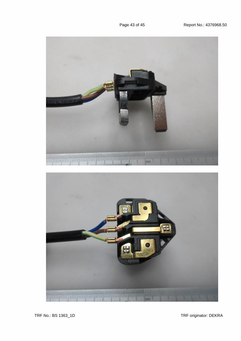
Page 43 of 45 Report No.: 4376968.50
TRF No.: BS 1363_1D TRF originator: DEKRA
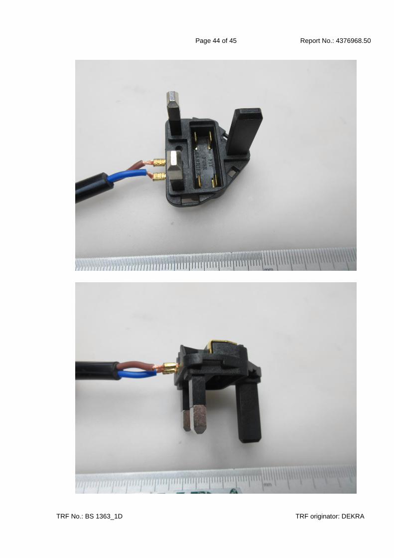
Page 44 of 45 Report No.: 4376968.50
TRF No.: BS 1363_1D TRF originator: DEKRA

Page 45 of 45 Report No.: 4376968.50
TRF No.: BS 1363_1D TRF originator: DEKRA
*** End of Test Report Form ***