Embed Size (px)
Citation preview

TEST READINESS REVIEW
(TRR) Geocentric Heliogyro Operational Solar-sail Technology (GHOST)
DATE
Nicholas Busbey, Mark Dolezal, Casey Myers, Lauren Persons,
Emily Proano, Megan Scheele, Taylor Smith, Karynna Tuan
1

Presentation Sections
•Project Overview
•Schedule
•Project Budget
•Test Readiness
• Deployment Test
• Pitching Test
• Deflection Test
2
2

Project Purpose and Specific Objectives
• Purpose: Design, build, and test a heliogyro solar sail deployment and
pitching mechanism housed in a 6U CubeSat to improve current
technology
• Top Level Objectives and Requirements: • GHOST_001: Deploy a heliogyro solar sail in a 1G environment at a controlled rate between
1 and 10 cm/s
• GHOST_002 : Pitch solar sail blades in a repeatable periodic motion within error margin of 0.5˚
• GHOST_003: House adequate length of solar sail to achieve minimum characteristic
acceleration of 0.1 mm/s2
• GHOST_004: Withstand static loads experienced from contact points with the Canesterized Satellite
Dispenser (CSD) during launch and static loads experienced during ejection from CSD after
launch
• GHOST_005: Deployment and pitching system shall not exceed 10W of power.
Project Overview 3

3.0 1- G Controlled deployment of solar sails
3.1 Suspend CubeSat in 1G environment
3.2 Initiate deployment mechanism
3.3 Measure Controlled sail deployment
using motors
Concept of Operations: Testing Overview
4 Project Overview
GHOST project responsible for deployment
and pitching validation: Steps 3 and 5
3: Controlled Deployment
5: Solar Sail Root Pitch Control
(Major Tests to be Performed)
5.0 1-G Pitch control of blade reel module
5.1 Establish connection to pitching mechanism
5.2 Send appropriate pitch command
5.3 Measure resulting pitch angle
5.3.1 Measure actual pitch angle and compare
to expected pitch angle.
5.4 Ensure both actuators are capable of generating
synchronized – collective, ½ P, and 1P cyclic
root pitch deflections

Front View
Top View
Side View
Top View
Blade
Blade
C-Brackets Tip Mass
Stepper Motor
Ball Bearing
Hub
Servo Motors/Encoders
Servo Motor Clamps Motor Drivers
and PCB
“Launch Locks”
Project Overview 5
Blade Reel
Module (BRM)
Central Control
Module (CCM)
Theoretical (kg) Measured (kg)
BRM Outer Structure 0.717 0.670
CCM Outer Structure 0.999 1.060
Total 2.433 2.400
Mass Budget – In Progress
Theoretical (kg) Measured (kg)
BRM Total 1.306 TBD
CCM Total 1.263 TBD
Total 3.875* TBD
Mass Budget – Total
*Note: Theoretical mass estimation does not include misc. electrical parts
such as wiring, resistors, capacitors, etc.
Design Solution: Mechanical Overview
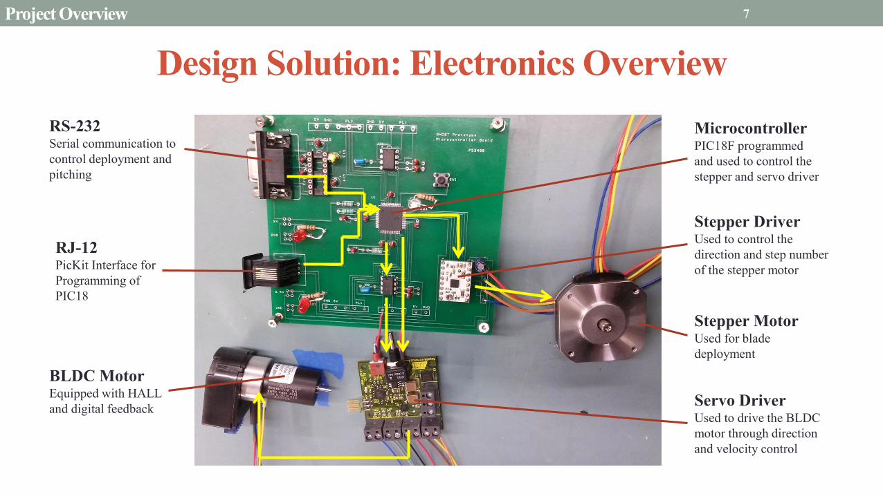
Design Solution: Electronics Overview
6
Microcontroller PIC18F programmed
and used to control the
stepper and servo driver
Stepper Driver Used to control the
direction and step number
of the stepper motor
BLDC Motor Equipped with HALL
and digital feedback
RS-232 Serial communication to
control deployment and
pitching
RJ-12 PicKit Interface for
Programming of
PIC18
Project Overview
Stepper Motor Used for blade
deployment
Servo Driver Used to drive the BLDC
motor through direction
and velocity control
7

Functional Block Diagram
Project Overview 7
Microcontroller (PIC)
Pitching
Motor (BLDC Motor)
Pitching
Driver
(Servo Driver)
Deployment
Motor (Stepper)
Deployment
Driver (Stepper)
Serial
Communication (RealTerm via RS-232)
HALL
Encoder
Digital
Encoder
DAC
Direction
PWM
Direction
Step
Voltage
Angular
Speed
Internal Position
Feedback
Position
Feedback

Presentation Sections
•Project Overview
•Schedule
•Project Budget
•Test Readiness
• Deployment Test
• Pitching Test
• Deflection Test
8
8

1/13 1/20 1/27 2/03 2/10 2/17 2/24 3/03 3/10 3/17 3/24 3/31 4/07 4/14 4/21 4/28
MSR TRR SFR PFR
Time (date)
Purchase
motors/drivers/PIC
Preliminary code
Electronic integration
Test code
Electronics/code
interface
Purchase
raw materials
Manufacture frame
Assemble bus
Manufacture
axles, brackets, and stabilizers
Integrate system
Deployment test
Pitching test
Structural Dynamics Tests
Ta
sks
GHOST Spring Schedule
Completed Still need to do
Key
Test procedures/set up
9 Schedule

Current Progress Pitching Axle Press Fit
to Motor Shaft
Stabilizers
PCB
Servo
Motor
Stepper
Motor
10 Schedule
Assembled Outer Structure
Deployment
Axle
Rolled Mylar
Blade

Presentation Sections
•Project Overview
•Schedule
•Project Budget
•Test Readiness
• Deployment Test
• Pitching Test
• Deflection Test
11
11

Project Budget
Part Cost Supplier Arrived?
2 Aluminum Sheets – 1/8”
thick $105.84 Metals Depot Yes
1 Aluminum Rod – 1/4”
diameter $1.96 Metals Depot Yes
1 Aluminum Rod – 7/16”
diameter $23.97 Metals Depot Yes
1 roll Kapton Tape – ¾”
wide $25.00 Unline Yes
Miscellaneous Screws,
Nuts, Bolts, etc. $66.37 McMaster-Carr Yes
Pic, DACs and Sipex Chip $30.00 Mouser Yes
Total Cost of Purchased
Components & Shipping
Projected Total Cost of
Remaining Components
Total Estimated Budget
Used
$1937.43 $400.00 $2337.43
12 Budget

Presentation Sections
•Project Overview
•Schedule
•Project Budget
•Test Readiness
• Deployment Test
• Pitching Test
• Deflection Test
13
13

Deployment Test Overview
14 Test Readiness - Deployment Test
• Design Requirements Satisfied:
1. Deploy solar sail in a 1G environment at a controlled rate.
2. User input changes sail deployment velocity and maintains
this rate within 1 cm/s.
• Objectives:
1. Verify GHOST subsystems perform together within error
tolerance of 1 cm/s.
2. Prove Deployment system responds to user rate input.
• Testing Strategy:
1. Mount CubeSat vertically at top of plywood scaffolding in
Fleming.
2. Input predetermined deployment rate and direction via
Realterm.
3. Record data and compare to expected performance.

5V 3.5V
15
Deployment Test Setup
• Mount to Plywood Scaffolding
• Calibrate camera to 3 meter window
• 3.5 and 5V Power Supply
• Power On (begins holding torque)
• Remove tip mass locks
• Command deployment at 5 cm/sec
• Measure Deployment Rate
• Compare footage to expected rate
• Repeated for variable rate testing
• Compare footage to predetermined deployment profile
Fleming High Bay
1 m
2 m
3 m
Scaffolding
Input via RealTerm
5 cm/s
CubeSat

Deployment Verification Tests
16
Test Design Requirement Objective Equipment
Component
Connection
• Stepper motor axle rotates when
connected to a waveform generator
• Ensure deployment system
electronics work properly before
loading code to PIC
• Oscilloscope
• Waveform
Generator
Deployment
System Power
Check
• Deployment system hardware does
not exceed 10W power
• Measure current and voltage drops
across electrical components
individually to calculate power
• Voltmeter
• Ammeter
Software
Integration
• Verify software is uploaded
• Verify deployment rate is received
by user input
• LED lights were designed in the
board to light up to verify software
• Computer
Variable
Deployment Rate
• Deployment can be stopped given
user command
• Deployment rate can be changed at
any time given user command
• Measure the pulses given by
stepper motor and compare to
predicted models
• Voltmeter
• Oscilloscope
Test Readiness - Deployment Test

Deployment Test: Electrical
• Measurements - Current (Ammeter)
- Voltage (Multimeter)
• Process
P = ∑ IV = ∑ 𝑉2
𝑅
P = 𝐼𝑚𝑉𝑚 + 𝐼𝑑𝑉𝑑 + 𝑉𝑚𝑐
2
𝑅𝑚𝑐
• Peak Expected Values
Micro-
controller
+5V +3.5V
Stepper
Driver
(Deploy
ment)
Stepper Motor
Res
Logic Supply
Logic Supply
Motor
Supply
System Voltage (V) Current (A) Power (W)
Microcontroller 5 (R = 150 Ω) 0.16
Stepper Driver 5 0.004 0.02
Stepper Motor 3.5 1.5 5.25
Total - - 5.43
17 Test Readiness - Deployment Test
A
V V

Deployment Software Calculate Circumference
C= 𝜋𝑑
Calculate length deployed with step
𝑠𝑡𝑒𝑝𝐿𝑒𝑛𝑔𝑡ℎ =𝐶 ∗ 𝑠𝑡𝑒𝑝𝐴𝑛𝑔𝑙𝑒
𝑓𝑢𝑙𝑙𝐶𝑖𝑟𝑐𝑙𝑒
Calculate the delay until the next step
𝑑𝑒𝑙𝑎𝑦𝑇𝑖𝑚𝑒 = 𝑙𝑒𝑛𝑔𝑡ℎ𝑆𝑡𝑒𝑝
2𝜋 ∗ 𝑑𝑒𝑝𝑙𝑜𝑦𝑅𝑎𝑡𝑒
Calculate reduction to diameter
𝑑 = 𝑑 −2 ∗ 𝑠𝑎𝑖𝑙𝑇ℎ𝑖𝑐𝑘𝑛𝑒𝑠𝑠 ∗ 𝑠𝑡𝑒𝑝𝐴𝑛𝑔𝑙𝑒
𝑓𝑢𝑙𝑙𝐶𝑖𝑟𝑙𝑐𝑒
Wait delayTime, then set motor outputs to
HIGH and then LOW to step the motor
stepAngle 1.8 Degrees
fullCircle 360 Degrees
sailThickness TBD
deployRate Variable which can
be set via interupt
To Test:
- Can reach deployment
routine via interrupt
- Can maintain constant
deployment rate and
deploys in within error
margin of 1 cm/s
18 Test Readiness - Deployment Test

Presentation Sections
•Project Overview
•Schedule
•Project Budget
•Test Readiness
• Deployment Test
• Pitching Test
• Deflection Test
19
19
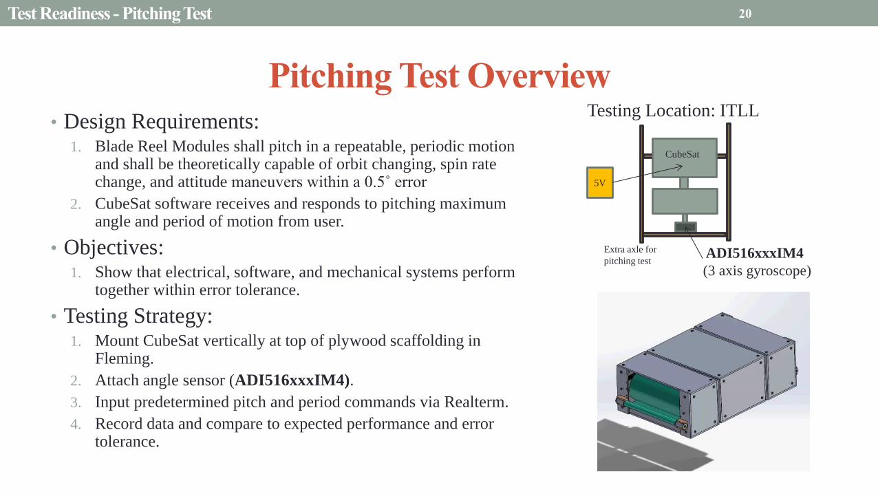
Pitching Test Overview
• Design Requirements: 1. Blade Reel Modules shall pitch in a repeatable, periodic motion
and shall be theoretically capable of orbit changing, spin rate change, and attitude maneuvers within a 0.5˚ error
2. CubeSat software receives and responds to pitching maximum angle and period of motion from user.
• Objectives: 1. Show that electrical, software, and mechanical systems perform
together within error tolerance.
• Testing Strategy: 1. Mount CubeSat vertically at top of plywood scaffolding in
Fleming.
2. Attach angle sensor (ADI516xxxIM4).
3. Input predetermined pitch and period commands via Realterm.
4. Record data and compare to expected performance and error tolerance.
20 Test Readiness - Pitching Test
Testing Location: ITLL
Extra axle for
pitching test ADI516xxxIM4
(3 axis gyroscope)
5V
CubeSat

0 200 400 600 800 1000 1200 1400 1600 1800-2
-1.5
-1
-0.5
0
0.5
1
1.5
2
2.5
3
Time (seconds)
Pitch R
ate
Sent
to S
erv
o (
degre
es)
Pitch rate response (1P, hP collective) - Oscillating Error of 0.5 deg, Period of 60 sec
Ideal Rate
Rate Sent
Pitch Rate Response (1P, hP collective) – Oscillating Error of 0.5°, Period of 60 sec P
itch
An
gle
sen
t to
Ser
vo (
deg
rees
)
Pitching Test Overview: Expected Results
21
0 200 400 600 800 1000 1200 1400 1600 1800-2
-1.5
-1
-0.5
0
0.5
1
1.5
2
2.5
3
Time (seconds)
Pitch R
ate
Sent
to S
erv
o (
degre
es)
Pitch rate response (1P, hP collective) - Oscillating Error of 0.5 deg, Period of 60 sec
Ideal Rate
Rate Sent
Pitch Rate Response (1P, hP collective) – Oscillating Error of 0.5°, Period of 60 sec) P
itch
Rat
e S
ent
to S
ervo (
deg
ree)
0 200 400 600 800 1000 1200 1400 1600 1800-20
-15
-10
-5
0
5
10
15
20
Time (seconds)
Pitch A
ngle
( d
egre
es)
Pitch angle response (1P, hP collective) - Error margin 0.5 deg, Period of 60 sec
Upper Limit
Lower Limit
Pitch Angle Response
Pitch Angle Response (1P, hP collective) –Error Margin 0.5°, Period of 60 sec P
itch
An
gle
(d
egre
es)
Begin at 1-P:
• Period = 60 sec
• Amp = 15˚
Transition to half-P:
• Period = 120 sec
• Amp = 15˚
Transition to Collective
• Period = 0 sec
• Amp = 15˚
Time (seconds)
Test Readiness - Pitching Test

Pitching Verification Tests
22
Test Design Requirement Objective Equipment
Component
Connection
• Servo motor axle rotates when driver
receives constant voltage
• DAC receives PWM signal and outputs
constant voltage
• Ensure deployment system
electronics work properly before
loading code to PIC
• Oscilloscope
• Waveform
generator
• Power supply
Pitching System
Power Check
• Deployment system hardware does not
exceed 10W power
• Measure current and voltage drops
across electrical components
individually to calculate power
• Voltmeter
• Ammeter
• Power supply
Servo Motor
Voltage
Calibration
• Single servo must use no more than 5W
power
• Motor is designed to have a peak
voltage of 5V
• Need calibration to model system
power
• Voltmeter
• Power supply
• Ammeter
Software
Integration
• Verify software is uploaded
• Verify deployment rate is received by
user input
• LED lights were designed in the
board to light up to verify software
• Computer
Variable Pitch
Period and
Amplitude
• Pitch profiles: collective, 1P, and ½P
• Pitching system capable of deflecting
180°
• Measure the angles rotated by servo
motor and compare to predicted
models
• Voltmeter
• Oscilloscope
Test Readiness - Pitching Test

Electronics Pitching Test
• Measurements - Current (Ammeter)
- Voltage (Multimeter)
• Process
P = ∑ IV = ∑ 𝑉2
𝑅
P = 𝐼𝑚𝑉𝑚 + 𝐼𝑑𝑉𝑑 + 𝐼𝑒𝑉𝑒+ 𝑉𝑚𝑐
2
𝑅𝑚𝑐
• Peak Expected Values
Micro-
controller
DAC
+5V Res
Servo
Driver
(Pitching)
Servo Motor
Encoder
Logic Supply
Logic Supply
Motor
Supply Encoder
Supply
System Voltage (V) Current (A) Power (W)
Microcontroller 5 (R = 150 Ω) 0.16
Servo Driver 5 0.025 0.13
Servo Motor 5 1 5.00
Encoder 5 0.023 0.11
Total - - 5.40
23 Test Readiness - Pitching Test
A
V
V
V

Pitching Software
Calculate current angles desired
• Current desired angle
• “Next step” desire angle
Update maximum angle, A Update
Period, P Global Variables
Convert to velocity (PWM signal)
• Adjust for error calculated
θ𝑎𝑐𝑡𝑢𝑎𝑙
Compare previous desired angle to
current actual angle
• Error = θ𝑝𝑟𝑒𝑣 - θ𝑎𝑐𝑡𝑢𝑎𝑙
Send Angular Velocity
24
• Controller inputs Maximum angle, period of rotation
• Follows θ𝑛𝑒𝑥𝑡 = (θ𝑑𝑒𝑠𝑖𝑟𝑒𝑑 + 𝑒𝑟𝑟𝑜𝑟) ∗ sin(2π𝑡/𝑃)
• Sends angular velocity:
ω𝑠𝑒𝑛𝑡 = − 2π𝑃 θ𝑑𝑒𝑠𝑖𝑟𝑒𝑑 + 𝑒𝑟𝑟𝑜𝑟 cos(2π𝑡
𝑃)
• Time t resets to zero at the start of each period
• Angle and Period may be changed dynamically
Test Readiness - Pitching Test
Presentation Sections
•Project Overview
•Schedule
•Project Budget
•Test Readiness
• Deployment Test
• Pitching Test
• Deflection Test
25
25

Deflection Test
𝐹 = 𝑘𝑑
where F is the applied force
on the right BRM and d is
the displacement
The stiffness k can be
determined
𝝎 =𝒌
𝒎
where ω is the modal
frequency and m is the
mass of the system
26 Test Readiness - Deflection Test
F
Analysis assumes CubeSat as three hollow pieces (with center
of mass in the center of each respective part) and two
composite rods along X-axis
X-axis
F
d
Clamp left BRM to table
k = 1.4 × 10⁸ N/m
ω = 767.8 Hz
Testing Location:
Aerospace Shop
Calculated modal frequency is larger than the peak
frequency we expect to experience

Deflection Verification Tests
27 Test Readiness – Electrical System Testing
Test Design Requirement Objective Equipment
Static Load • CubeSat walls shall not break in
shear stress under loads of 169N
• Ensure that the structure itself will
not fail under launch loads
• Weights
• Table
Axial
Compression
• CubeSat walls shall not deflect
greater than 1% under 44N force
experienced by CSD push
• During the ejection of the CSD
container, the CubeSat structure
will stay intact
• Dial indicator
(measure)
• Weights
CCM Deflection • Central command module shall not
deflect more than 1% during load
of 169N experienced under 100 G
• The pitching axels won’t fail under
loads on the CCM
• Weights
• Dial indicator
BRM Deflection • Blade reel modules shall not
deflect more than 1% during load
of 169N experienced under 100 G
• The pitching axels won’t fail under
loads on the BRM
• Weights
• Dial indicator

Thank you!
Questions?
28

Deployment Test Considerations
Remove Screws and Washers from
Tip Mass for Deployment
29
Tip mass is secured with washers and screws to
C-brackets for ease of transfer
Both screws and washers will be removed during
testing so blade and tip mass can deploy correctly
Deployment Test

Tolerance of Blade Axle Stabilizers
• For solar blade to deploy smoothly and avoid
ripping, Mylar blade must not contact front face
plates of Blade Reel Module:
• Due to geometric constraints, this leaves a tolerance
of ~3.8˚ in the horizontal alignment of the blade
deployment axle and stabilizers
• Significant to make sure the deployment axle and
stabilizer arrangement is not vertically tilted as to
impart a significant torque on the spacecraft due
to the misalignment of the deployed blades
• Assuming a restriction of erroneous torque being less
than ~3% of the maximum torque, the tolerance of the
alignment vertical tilt is ~0.66˚
Key: Perfect Alignment
Absolute Tolerance
θmax = 3.8˚ (horizontal),
0.66˚ (vertical)
30 Deployment Test

Pitching Test Considerations
Remove Screws and Nuts from inside CCM for Pitching
31 Pitching Test
Screw and nut hold the BRM to the CCM for
ease of transfers, simulated “launch locks”
Top wall of CCM must be unscrewed to remove
“launch locks” and replaced
Tool will be inserted into front of BRM to hold
nut while screw is taken out

Drawing Tree – Parts List 32 Appendix
Part Name Part Number Distributor Quantity Stock Stock Quantity Ordered? Completed? Total Cost Theoretical Mass Measured Mass Notes
BRM Side Wall
S318T6 Metals Depot
4
1/8" Thick Aluminum 2 Y
Y
$105.84
0.062 0.060 May want to cut out triangles
BRM Back Wall 2 Y 0.168 0.160
BRM Top and Bottom Wall 4 Y 0.132 0.130
BRM Left Front Wall 2 Y 0.0245 0.020
BRM Right Front Wall 2 Y 0.0245 0.020
CCM Side Wall 2 Y 0.0964 0.100 May want to cut out triangles
CCM Front and Back Wall 2 Y 0.15 0.160
CCM Top and Bottom Wall 2 Y 0.215 0.230 May want to cut out triangles
Left Blade Stabilizer 2 Y 0.023 0.023
Right Blade Stabilizer 2 Y 0.018 0.017
Corner Cube 99108A130 McMaster 24 5/8 x 5/8 x 12" Aluminum Key Stock 2 Y Y $22.86 0.009 0.010
Blade Deployment Axle R314 Metals Depot 2 1/4 x 24" Aluminum Axle 1 Y Y $1.96 0.0136 0.013 Needs to be press fit onto stepper motor
Pitching Axle R3716 Metals Depot
2 7/16 x 24" Aluminum Axle 1 Y
Y $4.94
0.0059 0.010 Needs to be press fit onto servo motor
Tip Mass 2 N 0.046
Hub N/A Matt Rhode 2 3/2 x 3/4" Aluminum Cylinder 2 N/A Y $0.00 0.041 0.043
C-Brackets N/A Matt Rhode 4 4 x 3/4 x 3/10" Aluminum Block 1 N/A N $0.00 0.0056
Servo Motor Clamps N/A Matt Rhode 4 1 x 1/2 x 1/2" Aluminum Block 1 N/A N $0.00 0.0033
Stepper Motor SS2421-5011 Polulu 1 N/A N/A Y N/A $59.95 0.07 0.073
Servo Motor 2036U012BK312+OPEC05 Micromo
2 N/A N/A Y N/A $372.10
0.05 0.080 Encoder and motor ordered together, company interfaced them for us
Encoder HEDM5500J06 2 N/A N/A Y N/A 0.085
Rolled Blade N/A NASA LaRC 2 N/A N/A Y N $0.00 0.393 Theoretical mass based off entire blade length
Kapton Tape Unline 1 1 roll, 3/4" wide 1 Y Y $25.00
PIC 18F87K22 Mouser 1 N/A N/A Y N/A $5.29 0.006667
0.080 DAQ MAS522CPA Mouser 2 N/A N/A Y N/A $12.02
Sipex chip SP232EEP Mouser 1 N/A N/A Y N/A $1.05
PCB Board Advanced Circuits 1 N/A N/A Y N $33.00 0.034
Stepper Motor Driver DRV8834 Polulu 2 N/A N/A Y N/A $9.95 None 0.070
Servo Motor Driver ATA6832-DK Atmel 2 N/A N/A Need 1 N/A None Currently only have 1 because of supply shortage with distributor
Misc. Electronics parts N/A JB Saunders N/A N/A N/A N N ~$50.00 Wires, resistors, capacitors, etc…
Flathead Torx 92703A207 McMaster 72 4-40 x 5/16" 2 Y Y $15.20 0.00045 0.00040 Connecting all walls to cubes
Friction-Resistant Shoulder 95446A652 McMaster 2 10-32 x 1/4 x 7/16" 2 Y Y $5.76 0.00770 Launch Locks
Flathead Phillips 91771A053 McMaster 20 0-80 x 5/32" 1 Y Y $8.62 0.00013 Connecting stabillizers to walls
Flathead Phillips 91771A170 McMaster 20 1-72 x 1/2" 1 N N $13.93 0.00026 Connecting tip mass to walls
Hex Nut 90545A111 McMaster 2 10-32 x 3/8 W x 1/8" H 2 N N $5.26 0.00363 Launch Lock Nuts
Set Screw 92313A109 McMaster 8 4-40 x 1/2" 1 N N $10.00 0.00064 Securing pitching axle into hub
Flathead Phillips 91771A168 McMaster 8 1-72 x 3/8" 1 N N $12.78 0.00026 Connecting servo motor clamps to walls
Flathead Phillips 91771A175 McMaster 4 1-72 x 1" 1 N N $9.64 0.00026 Connecting servo motor clamps together
Hex Nut 90480A002 McMaster 12 1-72 x 5/32 x 3/64" 1 N N $2.92 0.00013 Nuts for connecting servo motor clamps to walls and together
Washer 90107A003 McMaster 4 1/8 ID x 1/4" OD 1 N N $2.64 0.00013

Electronics Testing Overview
• Design Requirement
• 10 Watt power constraint
• Objective
• Control pitching and deployment system
independently to alleviate
power draw
• Testing Strategy
• Test pitching and deployment
system components power independently
• Calibrate servo motor voltage input
• Compare measured voltage and
current across all subsystems to
expected amount
Micro-
controller
+5V +3.5V
DAC
Stepper
Driver
(Deploy
ment)
Stepper Motor
Res
Servo
Driver
(Pitching)
Servo Motor
Encoder
Logic Supply
Logic Supply
Logic Supply
Motor
Supply
Motor
Supply Encoder Supply
33 Test Readiness

Software Testing Overview
• Design Requirement
• Asynchronous communication
• Objective
• Command pitching and deployment systems
• Be able to change pithing and deployment information
• Stop functions at any time
• Testing Strategy
• Test code on computer for expected behavior before integration
• Run individual functions on hardware to debug
• Run full system checks
34 Test Readiness

CubeSat Bus
CDH Pitch Servo
Motor
Gear
Blade Reel
Module
BPCS SSDM
Solar Sail
Pitch
VC
τM
τB
θ
Deployment
Stepper Motor
Shaft
Gear
System
τA
τC
τG
Solar
Blade
Solar Sail
Deployment
Ground Station
(User Input)
Com
man
ds
via
Inte
rrupts
Power Encoder
5 V
EPS
3.5 V
Deployment
Software
Step Pulse
Pitching
Software
Power
35 Test Readiness
Functional Block Diagram

Pitching Capabilities
• Collective Pitch Profile - spacecraft spin-up
• 𝑀1 is net moment vector that demonstrates increasing/decreasing spin
36 Appendix

Pitching Capabilities
• Cyclic Pitch Profile - Orbit Raising Maneuver
• 𝐹1 is net force vector that demonstrates in-plane thrust
• Used for orbit raising/lowering maneuvers
37 Appendix

Pitching Capabilities
• h𝑃 Pitch Profile – Precesses angular momentum vector
• 𝑀2 is net moment vector that demonstrates movement of gyro rotational axis
• Used to reorient SC towards sun
38 Appendix

Critical Project Elements
• Cut, attach, and roll the
aluminized mylar solar sail and
maintaining a straight blade
• Integration between the
software and the servomotor
• Manufacturing and aligning the
deployment axle and stepper
motor within alignment of 4°
• Manufacturing and aligning the
pitching axles with servo
motors within alignment of 1°
Project Overview 39

Major Changes in Project Schedule
• Software took a week longer than scheduled
• Integration and test got pushed back a week
• Added an extra week to create the test procedures and set up
• Moved deployment and pitching test to right after the TRR all the way to a week after
spring break
• Have four weeks to complete tests
• Created a stiffness/deflection test
• Have two weeks to complete test
• Electronics Assembly is done
• Mechanical Assembly is done
40 Schedule
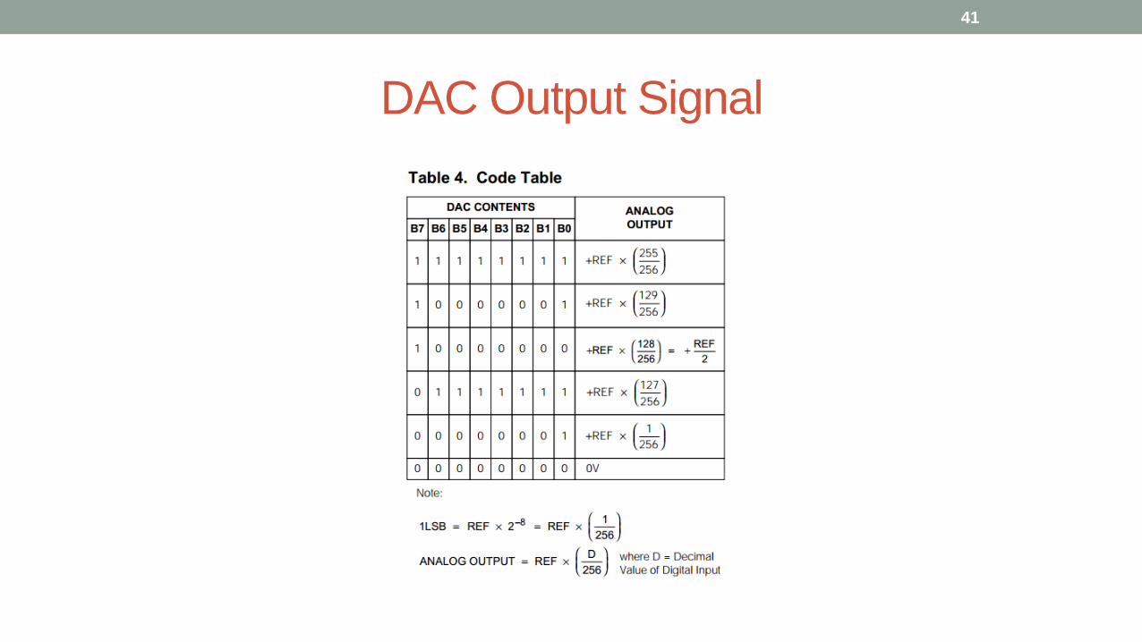
DAC Output Signal
41