Embed Size (px)
Citation preview

WiMax Test Plan Procedures - 1 - SUIRG, February 2008
Test Plan & Procedures
for
Measurement of WiMAX to FSS Interference
[Addendum to SUIRG WiMax Field Test Report]
Prepared by: Adam Edwards, SES-NewSkies/SUIRG
Robert Ames, SUIRG Kenneth Carrigan, US Navy NSWC Dahlgren
Reviewed and approved by:
SUIRG WBU/ISOG GVF NABA US Navy SAP-REG WTA

WiMax Test Plan Procedures - 2 - SUIRG, February 2008
Test Plan and Procedures for Measurement of WiMAX to FSS Interference
Objective: Measure the interference level generated by WiMAX transmission into a Fixed Satellite Service (FSS) satellite receiving station by taking measurements of C/N, BER and digital power of a test satellite channel. The testing was performed in 2 phases where during phase 1 the FSS antenna was fixed and a WiMAX subscriber unit was moved to several locations with various angles and distances to the FSS antenna. During Phase 2 the WiMAX base antenna was fixed at a height of 50 meters on a tower and the FSS antenna was moved to several locations with various angles and distances from the WiMAX antenna. Figure 1 shows the typical test set-up for both phases.
Test Equipment and Set Up
The following equipment was used during the test. The connection of test set up is shown in Figure 1. The specification of antenna system and WiMAX equipment are given in Appendix 1.
Item Description Manufacturer Model
(a) 2.4-meter Diameter Antenna with C-band Dual Feed horn
Prodelin Series 1244
(b) LNA in 3.4 – 4.2 GHz Band Vertex/RSI LCC4S30
(c) Down Converter Novella SatComs
BD500 Series
(d) Coupler Narda
(e) WiMAX Base Station Equipment Proxim 3500-B00-AM0 – MP.16 3500
(f) WiMAX Base Station Panel Antenna Proxim 3338-A00-120
(g) WiMAX Subscriber Station Equipment Proxim 3500-S00-AM0 – MP.16 3500
(h) WiMAX Subscriber Station Antenna Proxim 3437-A00-018
(i) Portable Handheld GPS GARMIN GPS 45XL
(j) Spectrum Analyzer H/P-ESA 4407B
(k) Digital Satellite Receiver Tandberg 1260 Mpeg2-DVB
(l) 15” LCD Television Set Polaroid FLM-1511
(m) Power Inverter
(n) Misc. cables & connectors

WiMax Test Plan Procedures - 3 - SUIRG, February 2008
Test Methodology The interference effect to satellite signal reception from Satellite NSS 806 @ 319.5E was measured in this test during phase 1 and phase 2. The testing was done in two phases at two difference locations: Phase 1 was done in Punta Gorda, Florida where the WiMAX transmitter was located at several different locations while the FSS antenna remains fixed. Phase 2 was conducted in the Maryland and Virginia area where the WiMAX antenna was mounted on a tower at 50 meters and the FSS antenna moved to various distances and angles from the WiMAX antenna. WiMAX frequencies used for the test are detailed in the following test procedure. The C/N, BER and digital power of a video program channel was measured directly at the LNA output. The data collected was reviewed and compared with that of theoretical analysis. The following outlines the steps involved in the test. The detailed test procedures are provided in
Appendix 1.
Phase 1- Punta Gorda, Florida
• A carrier was transmitted from a known location on Satellite NSS 806, utilizing various modulation and coding techniques.
• Aligned the satellite antenna to receive video program channel at 3,515 MHz.
• Measured at the D/C output the C/N, BER and digital power of the carrier @ 3,515 MHz to establish a baseline.
• Located the WiMAX transmitter at varying distances and angles relative to the satellite antenna
using the GPS and make a measurement at each angle and distance.
• Adjusted the WiMAX transmitter to various frequencies and various output power levels.
• Measured the C/N, BER and digital power of the received signal at the D/C output and record the TV picture quality.
• Measured, with the spectrum analyzer, the WiMAX transmitter output power level within the immediate area of the C-Band antenna at the assigned WIMAX test frequency.
Phase 2- Maryland and Virginia Area along the Potomac River
• A carrier was transmitted from a known location on Satellite NSS 806, utilizing various modulation and coding techniques.
• Aligned the satellite antenna to receive video program channel at 3,515 MHz.
• Measured at the D/C output the C/N, BER and digital power of the carrier @ 3,515 MHz to established a baseline.
• Located the WiMAX transmitter antenna at an elevation of 50 meters on a tower.
• Made measurements at the FSS antenna at varying distances and angles relative to the
WiMAX antenna.
• Adjusted the WiMAX transmitter to various frequencies and various output power levels.
• Measured the C/N, BER and digital power of the received signal at the D/C output and recorded the TV picture quality.
• Measured, with the spectrum analyzer, the WiMAX transmitter output power level within the immediate area of the C-Band antenna using a unity gain handheld antenna at the assigned WIMAX test frequency.

WiMax Test Plan Procedures - 4 - SUIRG, February 2008
Test General Notes 1. This procedure was verified and agreed upon by the following organizations:
SUIRG: Satellite Users Interference Reduction Group WBU-ISOG: World Broadcasting Union – Inter Satellite Operations Group GVF: Global VSAT Forum SAP-REG Satellite Action Plan Regulatory Working Group NABA: North American Broadcasters Association US Navy: NSWC Dahlgren WTA: World Teleport Association
2. The entire testing process could be witnessed by any interested party involved in the Satellite
Industry.
3. The “TV Picture Quality” result was based on the following: Grade 1: Excellent Broadcast quality Grade 2: Occasional Blocking, poor BER Grade 3: Frequent Blocking, Emergency Broadcasts only Grade 4: Unusable
4. Procedural steps A—J were to be repeated upon the insertion of the band pass filter to address the problem of LNA saturation; however, the LNA never saturated.
5. Spectrum Plots from the Analyzer were taken at every point during procedure using the
following settings: Span: 50Mhz RBW: 100Khz VBW: 1Khz 5dB/div (or a more applicable as deemed necessary during the test) Max hold or Video Averaging Techniques may be used if deemed necessary
6. Data Sheet Definitions
Site ID: Remote terminal location where measurements were made Nominal C/I0 @ LNA: Carrier to Interference Ratio at LNA output with no WiMAX
Carrier present. TV Picture Quality: See note 3 C/N (dB) WiMAX: Carrier to Noise Ratio of WiMAX transmit carrier RX BER: Receive Bit Error Rate as measured by the receiver C/I (d/B) LNA: Carrier to Interference Ratio @ LNA output with WiMAX carrier
present I @ LNA: Difference in Interference level with and without WiMAX carrier
present

WiMax Test Plan Procedures 5 SUIRG, February 2008
Figure 1: Typical test set-up
WiMax Test Plan Procedures - 6 - SUIRG, February 2008
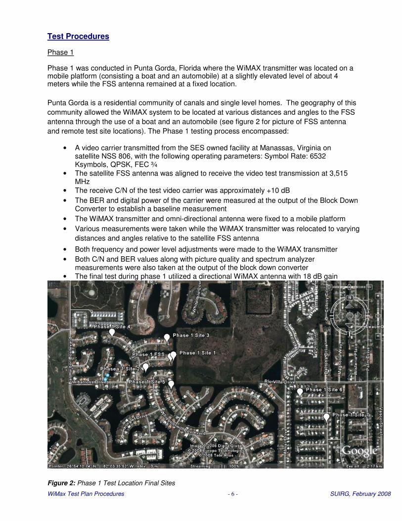
Test Procedures Phase 1 Phase 1 was conducted in Punta Gorda, Florida where the WiMAX transmitter was located on a mobile platform (consisting a boat and an automobile) at a slightly elevated level of about 4 meters while the FSS antenna remained at a fixed location.
Punta Gorda is a residential community of canals and single level homes. The geography of this
community allowed the WiMAX system to be located at various distances and angles to the FSS
antenna through the use of a boat and an automobile (see figure 2 for picture of FSS antenna
and remote test site locations). The Phase 1 testing process encompassed:
• A video carrier transmitted from the SES owned facility at Manassas, Virginia on satellite NSS 806, with the following operating parameters: Symbol Rate: 6532 Ksymbols, QPSK, FEC ¾
• The satellite FSS antenna was aligned to receive the video test transmission at 3,515 MHz
• The receive C/N of the test video carrier was approximately +10 dB
• The BER and digital power of the carrier were measured at the output of the Block Down Converter to establish a baseline measurement
• The WiMAX transmitter and omni-directional antenna were fixed to a mobile platform
• Various measurements were taken while the WiMAX transmitter was relocated to varying
distances and angles relative to the satellite FSS antenna
• Both frequency and power level adjustments were made to the WiMAX transmitter
• Both C/N and BER values along with picture quality and spectrum analyzer measurements were also taken at the output of the block down converter
• The final test during phase 1 utilized a directional WiMAX antenna with 18 dB gain
Figure 2: Phase 1 Test Location Final Sites

WiMax Test Plan Procedures - 7 - SUIRG, February 2008
Phase 1: FSS Antenna and Remote WiMAX Test Locations
FSS Antenna Location
N26°54’13.6” W82°03’47.8”
As the measurement process continued it became apparent that some pre-selected sites would not have provided any usable information and that additional locations were defined to provided additional data to support previous measurements. As a result, the sites as defined in the above chart were the actual measurement sites.
Phase 2
The Maryland and Virginia areas along the shores of the Potomac River allowed for longer
distance testing while maintaining a direct line-of-sight between the WiMAX antenna and the FSS
system (see figure 3 for picture of FSS antenna test set-up location and figure 4 for the water
tower where the WiMAX hub antenna was installed). Figure 5 provides an overview of the Phase
2 sites including the water tower and the 2 FSS test sites identified as short and long to
distinguish the distances of 3.5 km and 12 km, respectively.
Figure 3: Phase 2 WiMAX antenna location
Figure 4: Phase 2 test locations
Phase 2 Antenna Locations
WiMAX antenna on Water Tower FSS Antenna Short FSS Antenna Long
N38°20’12” W77°12’32” N38°21’58” W77°13’11” N38°23’47” W77°19’03”

WiMax Test Plan Procedures - 8 - SUIRG, February 2008
The Phase 2 testing process encompassed:
A carrier transmitted from an SES owned facility in Manassas, Virginia on the NSS 806 satellite @ 319.5 East, with the following operating parameters: Symbol Rate: 6532 Ksymbols, QPSK, FEC ¾
The WiMAX antenna and hub transmit equipment were located on a water tower (approximately 50 meters elevation) along the shores of the Potomac River in Northern Virginia
The satellite FSS antenna was mounted onto a mobile platform and aligned at the various locations to receive the test carrier at 3,515 MHz
The receive C/N of the test carrier was approximately 10 dB
The BER and digital power of the carrier were measured at the output of the Block Down Converter to establish a baseline measurement
The FSS antenna was relocated to varying distances and angles relative to the
WiMAX antenna and a measurement was made at each location
Operational Test Procedures
Tests were conducted using various different operational modes as described below: Step
#
Operational Test Procedure
Satellite Name & Orbital Location: NSS 806 Align the satellite antenna to receive video carrier at 3,510 MHz and measure. A1 Set the WiMAX transmitter to transmit : MHz a) 3400 b) 3450 c) 3500 d) 3550 e) 3600 A2 Set the output of the WIMAX transmitter to: dBm
a) 5 b) 10 c) 15 d) 20
e) 25
A3 Locate the WIMAX transmitter from Satellite Antenna: Meters a) 20 b) 75 c) 150 d) 300 e) 500 f) 1000 A4 Nominal angle of WIMAX transmitter towards FSS antenna dependent upon available
locations. Degrees a) 0 b) 45 c) 90 d) 135 e) 180 For the purposes of this test, particular attention was paid to the following:
i. Output level from the WIMAX transmitter (A2) ii. Distance of the WIMX transmitter from the Satellite antenna.(A3) iii. Angle of WIMAX transmitter from Satellite antenna bore sight (A4)
If required, testing will also be conducted using different transmit frequencies from the WIMAX transmitter.

WiMax Test Plan Procedures - 9 - SUIRG, February 2008
Sample of Test Procedures and Measurement Data Sheet I. Test Configuration: A1B1C1: WIMAX transmitter 3400 MHz @ 5 dBm w/ 20 meter distance and various angles
Step # Procedures
Align the satellite antenna to receive @ 3,510 MHz and take measurement. A1 Set the WIMAX transmitter to transmit 3400 MHz B1 Set the output of the WIMAX transmitter to 5 dBm C1 Locate the WIMAX transmitter 20 meters from Satellite Antenna
D1-4 Angle of WIMAX transmitter towards FSS antenna- Test site IDs A1, A2, A3, A4
E Measure Results and record below
Results
Site ID TV Picture Quality
C/N (dB) WIMAX
BER Rx Signal
C/N (dB) LNA
WiMAX power @ Satellite Antenna (dBm)
A1
A2
A3
A4
Test Configuration A1B2C1: WIMAX transmitter @ 10 dBm w/ 20 meter distance and various angles
Results
Site ID TV Picture Quality
C/N (dB) WIMAX
BER Rx Signal
C/N (dB) LNA
WiMAX power @ Satellite Antenna (dBm)
A1
A2
A3
A4
Test Configuration A1B3C1: WIMAX transmitter @ 15 dBm w/ 20 meter distance and various angles
Results
Site ID TV Picture Quality
C/N (dB) WIMAX
BER Rx Signal
C/N (dB) LNA
WiMAX power @ Satellite Antenna (dBm)
A1
A2
A3
A4
Test Configuration A1B4C1: WIMAX transmitter @ 20 dBm w/ 20 meter distance and various angles
Results
Site ID TV Picture Quality
C/N (dB) WIMAX
BER Rx Signal
C/N (dB) LNA
WiMAX power @ Satellite Antenna (dBm)
A1
A2
A3
A4
Test Configuration A1B5C1: WIMAX transmitter @ 25 dBm w/ 20 meter distance and various angles
Results
Site ID TV Picture Quality
C/N (dB) WIMAX
BER Rx Signal
C/N (dB) LNA
WiMAX power @ Satellite Antenna (dBm)
A1
A2
A3

WiMax Test Plan Procedures - 1 - SUIRG, February 2008
APPENDIX 1: Equipment Specifications Appendix 1A: Antenna System Equipment Specifications 1A-1: Receive 2.4 meter FSS Antenna (Prodelin Model 1244)
See specification sheet Annex 1C.
1a-1.1 Receive FSS Antenna subsystems:
1a-1.1.1 C-band Dual Feed horn
1a-1.1.1.2 C-Band down-converter (Novella SatComs Model – BD511) See specification sheets Annex 1D 1a-1.1.1.3 LNA in 3.4 – 4.2 GHz Band (Model – Vertex/RSI LCC4S30 )
See specification sheets Annex 1E.
1A-2: WiMAX Base Station Panel Antenna (Proxim Model 3338-A00-120) Description: Outdoor 13 dBi, 120° Sector antenna for the 3.3-3.8 GHz frequency range. The 13 dBi, 120° Sector antenna is ideally suited for use with the MP.16 3500 base station.
Specifications:
Electrical
Part Number 3437-A00-018
Frequency Range 3300 MHz - 3800 MHz
VSWR 1.7:1 (max)
Gain 13 dBi
Polarization Vertical
HPBW/horizontal 120°
Downtilt 8°
Power Handling 6W
Impedance 50 Ohm
Connect or Type N-type Female
Mechanical & Environmental Specifications
Dimensions 500 x 200 x 30 mm
Weight 1.5 Kg
Temperature Range -45°C to 70° C
Humidity 144h @ 95%
Survival wind speed 220 Km/hr
Lightning Protection DC Grounded
Radome Color Gray, White
Radome Material Plastic

WiMax Test Plan Procedures - 2 - SUIRG, February 2008
1A-3: WiMAX Subscriber Station Panel Antenna (Proxim Wireless Tsunami WiMAX MP.16 3437
Outdoor, 18 dBi Flat Panel Subscriber Antenna) Description: Outdoor, 18 dBi Flat Panel antenna for the 3.3-3.7 GHz frequency range. The 18 dBi Flat Panel antenna is for use with the Proxim MP.16 3500 subscriber station.
Specifications: Electrical
Part Number 3437-A00-018
Frequency Range 3300 MHz - 3700 MHz
VSWR 1.5:1 (max)
Gain 18 dBi
Polarization Linear, vertical
HPBW/horizontal 18°
HPBW/vertical 18°
Power Handling 20 W
Impedance 50 ohms
Connector Type N-type Female
Mechanical & Environmental
Dimensions 305 x 305 x 25 mm
Weight 1.5 Kg
Temperature Range -40°C to 80° C
Humidity 95% @ 55° C
Survival wind speed 216 km/hr
Lightning Protection DC Grounded
Radome Color Gray - White
Radome Material PC, V-2

WiMax Test Plan Procedures - 3 - SUIRG, February 2008
APPENDIX 1B: WiMAX Base and Subscriber System Equipment Specifications 1.2.1 WiMAX Base Station (Proxim Tsunami 3500-B00-AMD) & Subscriber Station (Proxim Tsunami 3500-
S00-AM0) Technical Specifications
Equipment description: Consists of an all-outdoor, single sector base station and multiple subscriber configurations (integrated antenna or N-Connector for external antenna), the Tsunami MP.16 series offers a scalable, WiMAX certified system for the 3.5 GHz frequency band.
Tsunami™ MP.16 Series Highlights
Product Model MP.16 3500 Description WiMAX Forum Certified™ products for 3.5 GHz frequency band Applications • Broadband last-mile access for metropolitan and rural areas
• Voice, video and data transmission with optimal economics • Security and surveillance
Environments • Service provider and municipal broadband networks • Security and surveillance
Key Features Product complies with IEEE 802.16 - 2004 standard • WiMAX QoS for voice, voice, data • All-in-one, outdoor base station delivers scalable solution by allowing single sector deployments to grow into multi-sector deployments
SPECIFICATIONS Frequency Band 3.40 - 3.60 GHz Wireless Protocol 802.16-2004 Data Rate 25.4 Mbps QoS 802.16d QoS (WiMAX) Security • AES
• Radius base authentication of subscribers based on MAC address Form Factors • Base: ODU, N-connector
• Subscriber station: ODU, N-connector or Integrated 21 dBi Antenna
CONFIGURATIONS/ MODEL
WIMAX COMPLIANCE WARRANTY
FREQUENCY
DUPLEXING MODE
CHANNEL BANDWIDTH
INTEGRATED ANTENNA
ANTENNA PORT
DATA COMMUNICATION
PORT
SERIAL PORT / GPS PORT
NLOS & INTERFERENCE
MITIGATION FEATURES
OUTPUT POWER
(AT ANTENNA PORT)
MODULATION
3500-B00-AM0 – MP.16 3500 Base Station
3500-S00-AM0 – MP.16 3500 Subscriber Station
IEEE 802.16-2004 (WiMAX profile 3.5T1)
1 Year Parts and Labor
3.4 GHz to 3.6 GHz
TDD
3.5 MHz and 7 MHz
Gain 18 dBi (3,500 dBi only)
Connector N-Female, 50 ohms
Standard 10/100 Base-TX Ethernet, Manual/Auto Negotiate, Half/Full Duplex, RJ-45 RJ-45 Connector
OFDM 256 FFT, Adaptive Modulation, FEC
Up to 21 dBm
User Attenuation Control: Maximum BS Output Power configurable to 5-21 in one dB step
OFDM modulation, 256 FFT points; BPSK, QPSK, 16QAM, 64QAM

WiMax Test Plan Procedures - 4 - SUIRG, February 2008
FRAME DURATION
Modulation &
FEC
Rx Sensitivity
(10-6)
Minimum
C/I Spectral Efficiency
Burst Data
Rate,
Mbps Tg/Tb =
1/16
BPSK- 1/2 -95 dBm 4.5 dB 0.5 bps/Hz 1.4 Mbps
QPSK- 1/2 -92 dBm 6.6 dB 1 bps/Hz 2.8 Mbps
QPSK- 3/4 -90 dBm 8.9 dB 1.5 bps/Hz 4.2 Mbps
16QAM- 1/2 -87 dBm 11.9 dB 2 bps/Hz 5.6 Mbps
16QAM- 3/4 -84 dBm 15.2 dB 3 bps/Hz 8.5 Mbps
64QAM- 2/3 -80 dBm 19.3 dB 4 bps/Hz 11.3 Mbps
3.5 MHz
64QAM- 3/4 -78 dBm 21.3 dB 4.5 bps/Hz 12.7 Mbps
BPSK- 1/2 -92 dBm 4.5 dB 0.5 bps/Hz 2.8 Mbps
QPSK-1/2 -89 dBm 6.6 dB 1 bps/Hz 6.6 Mbps
QPSK- 3/4 -87 dBm 8.9 dB 1.5 bps/Hz 8.5 Mbps
16QAM- 1/2 -84 dBm 11.9 dB 2 bps/Hz 11.3 Mbps
16QAM- 3/4 -81 dBm 15.2 dB 3 bps/Hz 16.9 Mbps
64QAM- 2/3 -77 dBm 19.3 dB 4 bps/Hz 22.6 Mbps
RADIO PERFORMANCE
7 MHz
64QAM- 3/4 -75 dBm 21.3 dB 4.5 bps/Hz 25.4 Mbps
LOCAL MONITORING Serial/CLI RJ45 Port; Logging feature which logs to serial port, flash, RAM, or a
syslog server REMOTE MONITORING Telnet/CLI, HTTP, TFTP; SNMP v1, v2 (MIBII, Proxim MIBs, Bridge MIB, RIPv2
MPB, 802.16 MIB, Ether like MIB)
REMOTE MGMT ACCESS Wired-LAN or over-the-air
PASSWORD Multi-Level Password (user, administrator, installer, factory, engineering)
SUBSCRIBER AUTHENT X509v3 digital certificate; Radius Authentication and Provisioning; MAC
Address Table
VLAN Support for 802.1Q VLAN tagging and filtering; Support for transparent passing of 802.1Q-compliant VLAN tagged frames

WiMax Test Plan Procedures - 5 - SUIRG, February 2008
QOS Asymmetric Bandwidth: Uplink and Downlink CIR Control "committed
information rate" per service flow
Control: Uplink and Downlink MIR Control "maximum information rate" per service flow
Packet Classification: 802.1D/802.1Q/802.1p priority, IPTOS, VLAN ID, IP
source/destination address
Capabilities: source/destination port, Ethernet source/destination address ,IP protocol, and Ether type Scheduling: Best Effort, Universal Grant Services, Traffic is scheduled per service flow, enabling min/max bandwidth, priority, jitter and latency control for voice, video and data
OPERATING
TEMPERATURE
WEIGHT
DIMENSIONS
SAFETY STANDARDS
EMI STANDARDS
Outdoor Radio Unit (SS and BS) Indoor Power_ Injector
-40° to +60°C ° to +40°C
5.3 lbs 2.7 lbs
Packaged (BS, SSR): 14.57 x 13.70 x 8.19 in 5.12 x 3.62 x 2.64 in EN 60950 (CE) UL 1950 D3; CSA 22.2 N0.950 or CUL, VDE EN60950 or TUV. RSS-210 (Canada), ETS EN 301 489-1, 301 021, Conduction: FCC docket TS2 (SS), ETS 301 02ETS 3021 085 CS2 (BS) 20780 curve “B”ETS 302
. 085 VDE 0871 curve“ B Radiation: FCC class “B”
STATIONS BASE STATION: SUBSCRIBER STATION: Tsunami MP.16 Base Station Radio Tsunami MP.16 Subscriber Radio
Indoor Subscriber Station Power Injector (either with Type-N or Integrated Antenna)
4" Pole Mount Bracket 4" Pole Mount Bracket
Serial Dongle for Antenna Alignment Cable Termination Kit
Cable Termination Kit Power Cord (for Indoor Power Injector)
Quick Installation Guide Printed Quick Installation Guide CD-ROM containing User Documentation
Indoor Base Station Power Injector
ACCESSORY AND
SPARE KITS
Spare Power DC Injector (69823)
Surge Arrestor 5 GHz - Standard-N Female to Female (5054-SURGE)
POE (Power Over Ethernet) Surge Arrestor (70251);
WiMax Test Plan Procedures - 6 - SUIRG, February 2008
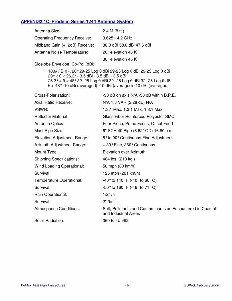
APPENDIX 1C: Prodelin Series 1244 Antenna System
Antenna Size: 2.4 M (8 ft.)
Operating Frequency Receive: 3.625 - 4.2 GHz
Midband Gain (+ .2dB) Receive: 38.0 dBi 38.0 dBi 47.6 dBi
Antenna Noise Temperature: 20° elevation 46 K
30° elevation 45 K Sidelobe Envelope, Co-Pol (dBi):
100λ / D θ < 20° 29-25 Log θ dBi 29-25 Log θ dBi 29-25 Log θ dBi 20° < θ < 26.3° - 3.5 dBi - 3.5 dBi - 3.5 dBi 26.3° < θ < 48° 32 -25 Log θ dBi 32 -25 Log θ dBi 32 -25 Log θ dBi θ > 48° -10 dBi (averaged) -10 dBi (averaged) -10 dBi (averaged) Cross-Polarization: -30 dB on axis N/A -30 dB within B.P.E.
Axial Ratio Receive: N/A 1.3 VAR (2.28 dB) N/A
VSWR: 1.3:1 Max. 1.3:1 Max. 1.3:1 Max.
Reflector Material: Glass Fiber Reinforced Polyester SMC
Antenna Optics: Four Piece, Prime Focus, Offset Feed
Mast Pipe Size: 6" SCH 40 Pipe (6.62" OD) 16.80 cm.
Elevation Adjustment Range: 5° to 90° Continuous Fine Adjustment
Azimuth Adjustment Range: + 30° Fine, 360° Continuous
Mount Type: Elevation over Azimuth
Shipping Specifications: 484 lbs. (218 kg.)
Wind Loading Operational: 50 mph (80 km/h)
Survival: 125 mph (201 km/h)
Temperature Operational: -40° to 140° F (-40° to 60° C)
Survival: -50° to 160° F (-46° to 71° C)
Rain Operational: 1/2" /hr
Survival: 2" /hr
Atmospheric Conditions: Salt, Pollutants and Contaminants as Encountered in Coastal and Industrial Areas
Solar Radiation: 360 BTU/h/ft2

WiMax Test Plan Procedures - 7 - SUIRG, February 2008
LOCAL OSCILLATOR
16. Local oscillator frequency: 5.15GHz 17. Frequency stability, 0°C to 50°C: 2 x 10⁻⁷ Option 1:
Option 2: Option 3: 18. External reference: 10MHz, 0dBm SPURIOUS
19. Image rejection: >75dB 20. In-band spurious (at 0dBm output):
<-60dBc 21. Out of band Spurious: ≤-40dBm
PHASE NOISE
22. 10Hz: <-45dBc/Hz 23. 100Hz: <-70dBc/Hz 24. 1kHz: <-80dBc/Hz 25. 10kHz: <-85dBc/Hz 26. 100kHz: <-95dBc/Hz 27. 1MHz: <-110dBc/Hz 28. Mains related: <-60dBc
MISCELLANEOUS
29. Power supply: 115V/230V ±10%
50/60Hz ±10%, 30VA
APPENDIX 1D: Novella SatComs BD511 C-band Block Down Converter
INPUT SPECIFICATION Options
1. Frequency range: 3.4 to 4.2GHz 2. Connector: SMA N-type 3. Impedance: 50Ω 4. Return loss: ≥20dB
OUTPUT SPECIFICATION
5. Frequency range: 950 to 1,750MHz (check model 6. Connector: SMA N-type 7. Impedance: 50Ω 8. Return loss: 15dB typical ≥20dB (*) 9. 1dB compression point: +10dBm 10. Third order intercept:: +20dBm
TRANSFER CHARACTERISTICS
11. Gain: 25d12. Gain ripple: over ±20MHz: ≤1dB p.t.p.
over input band: ≤3dB p.t.p
13. Gain stability,
0°C to 50°C: ±1dB 14. Gain slope: ≤0.02dB/MHz 15. Noise figure: 16dB typical
10-7
10-8
3 x 10⁻⁹
5MHz, 0dBm
30. Temperature:
Operating: 0° to 50°C
Storage: -40° to 85°C 31. Relative humidity: Operating: 0 to 90%
Storage: 0 to 95% 32. Summary alarm: NO and NC dry relay contacts via rear mounted 33. Summary alarm indication:
Front panel LED
.

WiMax Test Plan Procedures - 8 - SUIRG, February 2008
APPENDIX 1E: Vertex LNA Specifications, LC-4000 Series
Parameter
Notes
Min Nom./Typ.a Max
Units Frequency Range
Gain
Gain Flatness
VSWR
Noise Temperatureb Power Output at
1 dB compression 3rd Order Output
Intercept Point Group Delay
per 40 MHz AM/PM Conversion
Gain Stability
(Constant Temp) Gain Stability
Maximum Input Power
Connectors
Power Requirements
Operating Temperature
Band “C” Band “D”
Full band Per 40 MHz
Input Output
At +23 °C Versus temperature
Standard Option 2
Standard Option 2
Linear Parabolic Ripple
-5 dBm output power
Short term (10 min) Medium term (24 hrs) Long term (1 week)
Versus temperature
Damage threshold Desens. threshold,
5.825-6.425 GHz Input Output Power
Voltage Current, standard Current, with Option 2
3.6 4.2 3.4 4.2
60 64 66
±0.5 ±0.2
1.20 1.25 1.20 1.50
See Table 1
See Table 2
+10 +15 +20 +22
+20 +26 +30 +32
0.01
0.001 0.1
0.05
±0.1 ±0.2 ±0.5
-0.05
0
-10
CPR 229G Flange Type N Female
MS3112E10-6P (mate supplied) 12 15 24
140 180 200 240
GHz GHz
dB
dB dB
:1 :1
dBm dBm
dBm dBm
ns/MHz ns/MHz2 ns p-p
°/dB
dB dB dB
dB per °C
dBm dBm
V mA mA
°C
Notes: A: When there is only one entry on a line, the Nom/Typ column is a nominal value; otherwise it
is a typical value. Typical values are intended to illustrate typical performance, but are not guaranteed.
B: Maximum noise temperature at +23 °C at any frequency in the specified band.
# # # For more information visit www.suirg.org or email [email protected]