Embed Size (px)
Citation preview

1
Secretariat for building components
approved for drinking water
Test method for certain
water treatment devices
M01
October 2015 Version 1.1
–
2
Table of contents
Preface ................................................................................................................. 4
1. Introduction .................................................................................................... 5
2. Legislation ...................................................................................................... 6
3. Plants and appliances covered by the approval scheme ........................................ 7
4. Toxicological assessment and test programme .................................................... 8
5. Chemical analyses ........................................................................................... 9
5.1. Scope of testing ...................................................................................... 9
5.2. Test water .............................................................................................. 9
5.3. Test temperatures ................................................................................... 9
5.4. Preliminary treatment and handling of test samples ....................................10
5.5. Migration ...............................................................................................10
6. Bacteriological analyses ...................................................................................11
6.1. Test conditions .......................................................................................11
6.1.1. Water temperature (cold water) ......................................................11
6.1.2. Room temperature ........................................................................11
6.1.3. Water pressure .............................................................................11
6.1.4. Amount of water ...........................................................................11
6.2. Water quality of the test installation ..........................................................11
6.3. Installation ............................................................................................11
6.3.1. Test setup ....................................................................................12
6.3.2. Initial mechanical testing ...............................................................12
6.4. Practical implementation .........................................................................12
6.4.1. Test period ...................................................................................13
6.4.2. Flushing .......................................................................................14
6.4.3. Grafting .......................................................................................14
6.4.4. Test sampling ...............................................................................14
6.4.5. Analyses ......................................................................................14
6.4.6. Logbook.......................................................................................15
6.5. Test water .............................................................................................15
6.5.1. Production of test water .................................................................15
6.6. Grafting of the device ..............................................................................15
6.7. Test sampling.........................................................................................16
6.7.1. Sampling on the day of grafting ......................................................17
6.7.2. Test sampling during testing ..........................................................17
3
6.8. Analyses ................................................................................................17
6.8.1. Test water ...................................................................................17
6.8.2. Cold water samples .......................................................................18
6.9. Acceptance requirements for cold water devices .........................................18
6.10. Assessment of microbiological flora ...........................................................19
4
Preface
This test method is applied for certain water treatment devices (M01) for use in building
installations in connection with the approval scheme for building components that come
into contact with drinking water (the GDV, Approved for Drinking Water, approval scheme).
The test method is defined on the basis of the test method stated in the Danish document
“Orientering fra Miljøstyrelsen Nr. 6 2004 VA-godkendelse af vandbehandlingsanlæg til
montering i husinstallationer”. Moreover, the method is based on the experience gained
and the testing of the microbiological test applied in the Danish project “Miljøprojekt nr.
1105/2006 Opstilling af forsøgsprotokol til vurdering af mikrobiel vækst i forbindelse med
VA-godkendelse af større vandbehandlingsanlæg”.
On the initiative of the Danish Energy Agency, the test method M01 is developed in coop-
eration with Eurofins, DHI and the Secretariat for building components approved for drink-
ing water.
On 1 April 2013, the GDV scheme, “Approved for drinking water”, replaced the VA approval
scheme with respect to the mandatory approval of health-related properties for building
components that come into contact with drinking water. GDV approvals are issued by the
Secretariat for building components approved for drinking water. The requirements for the
GDV approval are defined in the Executive Order concerning the issue of approvals for
building components that come into contact with drinking water. For further information,
see the website of the GDV approval scheme: www.godkendttildrikkevand.dk.
5
1. Introduction
The test method M01 applies for certain water treatment devices for use in building instal-
lations that require an approval as building components that come into contact with drink-
ing water (the GDV approval). The background and statutory authority are described fur-
ther in chapter 2.
For the purpose of this report, water treatment devices mean plants and appliances in-
tended for a physical and/or chemical treatment of water, e.g. active carbon filters, ion
exchangers, membrane filters etc. The test method does not include pure mechanical treat-
ment such as dirt traps and sieves. The test samples subject for testing are described
further in chapter 3.
The purpose of the test method is to test the influence of water treatment devices on the
quality of the drinking water, either by influence of the unit itself or by changing the com-
position of the water.
A condition for achieving the GDV approval is that the building components used for drink-
ing water installations must not influence the drinking water in ways that are hazardous to
human health. The approval of building components that come into contact with drinking
water concerns the health-related properties of the building components, and it must en-
sure the quality of the drinking water. Thus, as stated in the Danish Executive Order con-
cerning the issue of approvals for building components that come into contact with drinking
water, building components must be suited for contact with drinking water so that the
drinking water as a minimum meets the quality requirements stated in the Danish Execu-
tive Order on water quality and inspection of water supply systems.
The test programme concerns general parameters as indicators of the influence on the
water quality, including microbiological parameters and specific substances, which depend
on the choice of materials for the parts that come into contact with water. The test pro-
gramme of relevant testing is determined on the basis of a toxicological assessment as
described in chapter 4.
The procedure for testing of water treatment devices with regard to the general parameters
and specific substances is described partly in chapter 5, Chemical analyses, and partly in
chapter 6, Bacteriological analyses.
The test method (i.e. testing and analyses) must be carried out by an independent labor-
atory, which has the necessary equipment and personnel to carry out the tests. The labor-
atory must also be accredited for testing and carrying out microbiological environmental
analyses.

6
2. Legislation
The approval of health-related properties of building components used for drinking water
installations in buildings is granted according to the Executive Order concerning the issue
of approvals of building components that come into contact with drinking water (the GDV
Executive Order), which is issued pursuant to the Building Act.
The requirements for approval in the GDV approval scheme include among others water
treatment devices, which are a part of or connected to the fixed water installations in a
building and thus connected to the public drinking water supplies, i.e. leading the drinking
water from the drinking water supply system to the draining point. Only water treatment
devices that are marketed and sold with this purpose are covered by the executive order
concerning the GDV approval scheme, and only such water treatment devices can obtain
a GDV approval.
The GDV approval of such water treatment devices is based on a health-related assessment
of the applied materials that come into contact with drinking water as well as necessary
testing of the influence of the device on the drinking water parameters. Which testing to
be carries out, depends on a concrete assessment of the individual device, the purpose of
the device and the materials that come into contact with drinking water.
This test method M01 can be accepted as a migration test for the included water treatment
devices in relation to Annex 1 of the GDV Executive Order, if the test method provides an
equivalent level of protection, and the Approvals Secretariat, thus, deems it adequate for
the water treatment device seeking the approval.
A condition for installing water treatment devices in building installations is that they are
installed in accordance with the Building Code. Simultaneously, it is a condition that water,
which is supplied to the drinking water installation, meets the drinking water requirements
of the Danish Ministry of the Environment; cf. the Executive Order on water quality and
inspection of water supply systems.
When installing water treatment devices for treatment of water centrally in a building, it
should be taken into consideration that certain types of treatment devices can change the
water quality, which might cause an increase in the corrosion or dissolution of metals in
the subsequent part of the drinking water installation. At worst, the quality requirements
for these might be exceeded.
Devices designed to treat water from supply plants that are not a part of the general water
supply system are not covered by the requirements for approval of the GDV Executive
Order.
7
3. Plants and appliances covered by the approval scheme
The test method covers water treatment devices for building installations used for drinking
water, regardless of whether the device is intended for water treatment centrally at the
entrance of the property or at the tap. Appliances and equipment used for water treatment
after the water has been drawn from the tap or installed only with a detachable hose
coupling or a corresponding connection to the fixed piping system for drinking water are
not covered by the regulations concerning the GDV approval.
Water treatment device means:
Units intended for the treatment of drinking water with the purpose of removing either
unwanted substances or flavours and odours from the drinking water, which can
emerge in the installation because of the residence time of the water in the installation.
Examples of such plants and appliances are softening units, demineralizer, carbon filters,
membrane filters, bacteriological filters, ion exchangers etc.
The approval scheme also includes drinking water coolers, which are a part of or attached
to the fixed drinking water installation and installed before the draining point.
Plants and appliances producing technical water are not covered by the GDV approval
scheme.
The GDV requirement for an examination of the influence on the drinking water quality
only covers the parts of the device that come into contact with drinking water. For drinking
water coolers without any kind of water treatment than cooling, the only requirement is an
assessment of the contamination from the materials.
The test method does not cover appliances and installations that mechanically work e.g.
as dirt traps and sieves. Typically, such building components are tested in the same way
as fittings, manifolds, valves etc.
An assessment must be made for each water treatment device to determine whether it is
most appropriately to test the device according to this test method or whether it should be
tested according to the general test requirements stated in Annex 1 of the GDV Executive
Order. The assessment must be included in the toxicological assessment of the water treat-
ment device in question.
If doubts whether the water treatment device should be tested according to this test
method or the general test requirements stated in Annex 1 of the GDV Executive Order,
you or your toxicological adviser are welcome to contact the Secretariat for building com-
ponents approved for drinking water.
8
4. Toxicological assessment and test programme
The toxicological assessment is carried out according to section 9(1) of the GDV Executive
Order. The scope is further specified in the instruction material for the GDV approval
scheme. Special reference can be given to:
Guidelines for building components approved for use with drinking water
Application guidelines
Relevant schedule of materials for the water treatment device in question
The toxicological assessment includes the materials of the parts of the water treatment
device that come into contact with drinking water. The assessment includes the general
parameters as well as the specific chemical substances and the bacteriological parameters.
Among these, the filter media (resin) and the polymeric materials that may occur are as-
sessed based on the chemical composition of the materials.
The applicant is responsible for having the toxicological assessment of the materials that
come into contact with drinking water or have an impact on it carried out.
The toxicological assessment must indicate which parameters require further examination
based on the information on the different types of materials in contact with water, which
the parts of the device in contact with water are made of.
The assessment is based on the following information:
Chemical names and/or trade names as well as the manufacturer of the different parts
that come into contact with drinking water
Contact time between the drinking water and the individual parts; usually all parts
that come into contact with water for more than 30 minutes should be assessed
Ratio between the water and the surface of the individual parts compared to the entire
device
Based on this information and the toxicological assessment of the device, the toxicological
adviser sets up a test programme for examining the migration of relevant substances from
the materials applied in the device.
All tests must be carried out by a laboratory accredited for carrying out the analyses in
question.
After testing, the toxicological adviser will carry out a toxicological assessment of the test
results for the water treatment device.

9
5. Chemical analyses
In principle, the device is tested as a whole (cf. note 1). All the components that are
included in a given installation, e.g. primary filter, UV lamps or buffer tanks, must be
included in the overall device for testing. If the manufacturer/supplier specifies special
installation packages for correct installation, these must be included in the testing. More-
over, it can be a question of special hoses and/or fittings, which ease the installation, but
are not a precondition for correct installation. These must be included in the testing as
well.
Note 1: If the water treatment device cannot be tested as a whole for physical/technical
reasons, the parts that come into contact with water and the resins are tested separately.
Reference is made to EN 12873-1 and the guidance material for the GDV Executive Order,
including the schedules of materials, which state the testing of area/volume ratio of 1
cm²/ml. For the resins, which are tested separately, reference is made to EN 12873-3.
5.1. Scope of testing
According to the test programme, water samples drawn after the water treatment device
(outlet) are analysed in terms of the relevant general parameters (colour, turbidity, flavour
and odour, TOC (VOC + NVOC), phenols and/or bacterial count with reference to Annex 1,
table 1 of the GDV Executive Order). Moreover, the samples are analysed in terms of the
specific substances determined by the toxicological assessment, including silver (see chap-
ter 4).
5.2. Test water
For the testing of the general water parameters and the specific substances, water without
chlorine (<0.2 mg chlorine per litre) conducted through pipes must be applied as test
water. The test water must not be influenced by the installations in the laboratory. If nec-
essary, water filtered through a millipore filter are applied for the test.
For the testing of TOC (VOC + NVOC) and certain chemical parameters, distilled water with
a TOC content of <0.1 mg per litre can be applied.
The water must not contain metals of any significance, i.e. the test water must meet the
requirements for drinking water when entering the building.
5.3. Test temperatures
Appliances and plants for treatment of cold water are placed on the cold water pipe. The
water temperature for the migration tests must be 23 °C, +/- 2 °C. If the appliances are
designed for placement in rooms with a higher temperature than normal room tempera-
ture, the appliance during testing must be placed in a room with this higher temperature.
The appliance must be marked with the maximum allowed installation/operation temper-
ature, which is determined by the manufacturer, and the appliance is tested at the specified
temperature.
10
5.4. Preliminary treatment and handling of test samples
In principle, the water treatment device is tested as a whole and connected to the power
and water supply of the laboratory according to the instructions that are delivered by the
manufacturer/supplier, including that regeneration occurs as under normal use. The device
is set up with a “normal” water consumption for a day (the ion exchangers must be regen-
erated at least once).
Be aware of the specifications of flow direction, flow rate and capacity.
The following values can be applied for a normal water consumption unless otherwise is
specified by the manufacturer/supplier:
Kitchen taps: 10 litre/minute
Larger plants: 20 litre/minute
A “normal” water consumption is imitated by tapping water for five minutes every hour of
the day.
During this period, it must be checked in order to see that everything works normally
according to the manual, including the function of the non-return valve as well as alarms
and closing devices when there is a need for replacing the cartridge/filters.
5.5. Migration
After the preliminary treatment, the water is replaced so that the device is filled with fresh
test water. The device stands connected for 24 hours (day 1) without any tapping of water.
Subsequently, test water equivalent to at least one bed volume (amount of water in the
appliance) is tapped, and the equipment stands for another 24 hours (day 2) without any
tapping of water (cf. note 2).
Subsequently, test water equivalent to at least one bed volume is tapped, and the equip-
ment stands for another 24 hours (day 3) without any tapping of water (cf. note 2).
At this point, water is tapped for the chemical analyses. A maximum of one bed volume of
water can be tapped. If this amount of water is not sufficient in order to carry out all the
chemical analyses, the test must be carried out on several devices.
The acceptance requirements must be meet for analyses carried out on test water from
day 3 (third extraction). Conditional to the results of the analyses, the testing can be ex-
tended by several days if it is assessed that the acceptance requirements can be met by
later extractions within a reasonable period of time (up to and including the ninth extrac-
tion). This only applies to measurements of turbidity, flavour and odour as well as TOC.
Note 2: For the ion exchangers, it should be ensured that the device regenerates before
the start of each period of standing. The same residence time of the water is applied, i.e.
the maximum amount of residence time before the next change of water/regeneration.
The maximum residence time depends on the individual device. The water sample is drawn
for analysis after the maximum residence time in the device and immediately before the
next regeneration, yet a maximum of 24 hours.

11
6. Bacteriological analyses
In connection with the bacteriological analyses, the device must be tested as a whole. All
components included in the installation, e.g. primary filter, UV lamps or buffer tanks, must
be included in the overall device for testing. It is not sufficient that the individual compo-
nents are approved separately. It is necessary to test the device as a complete unit. If the
manufacturer/supplier specifies special installation packages for correct installation, these
must be included in the testing. Moreover, it can be a question of special hoses and/or
fittings, which ease the installation, but are not a precondition for correct installation. These
must be included in the testing as well.
6.1. Test conditions
The following test conditions must be available during the entire test period:
6.1.1. Water temperature (cold water)
The temperature of the test installation must be between 5 C and 20 C, without any
temperature adjustment. Thus, the device should be mounted on the cold water supply.
6.1.2. Room temperature
A room temperature between 15 C and 25 C should be ensured in the room, where the
device is to be installed. It should also be ensured that the device is not placed in direct
solar radiation.
6.1.3. Water pressure
The device must be connected to a tap with an ordinary water pressure (more than 3.5
bar).
6.1.4. Amount of water
It should be ensured that the device functions at the flow rate specified by the supplier.
However, a variation of 10 % of the specified flow rate is acceptable.
6.2. Water quality of the test installation
Tap water with chlorine must not be applied.
The tap water in the test installation must meet the general requirements of water quality
stated in the Executive Order on water quality and inspection of water supply systems for
the time being in force.
6.3. Installation
The device must be installed in a test setup that is connected to the normal distribution
system of the laboratory/test site. The device is installed according to the instructions of
the manufacturer/supplier.
The test site does not have to be physically connected to the laboratory provided that the
test sampling, flushing and analyses can be carried out as prescribed in the test method

12
and kept under surveillance by the person responsible from the laboratory. All test samples
and analyses must be carried out by an accredited laboratory.
6.3.1. Test setup
The test setup consists of:
Draining point
Non-return valve
Quick-acting coupling
Connecting pipes (possibly with a sampling tap for drawing of water samples before
the device)
Coupling
Ball valve
Water treatment device
Ball valve or drain tap mounted on the device
It is important that all the building components used for the test setup together with the
water treatment device are approved for drinking water (GDV).
The non-return valve, which should be installed at the draining point, must ensure that the
tap water installation is not contaminated rearwards of the test setup.
Moreover, a flexible and transparent hose with a length of approximately two meters is
applied in connection with the grafting of the water. The hose should be able to withstand
boiling for a minimum of 15 minutes.
6.3.2. Initial mechanical testing
The device should be setup for use at a normal water consumption. Moreover, the device
should be tested prior to the microbiological testing to ensure that it is functional and
operates according to the instructions of the manufacturer/supplier.
Initially, the function of the device should be tested for two successive days by tapping
water for two minutes every hour in the course of a workday. A total of minimum 6 X 2
minutes should be tapped each day during the two days of testing.
If the equipment is installed with devices for backwashing of filter pulp etc., it should be
ensured that these operate at optimum level and according to the instructions of the man-
ufacturer/supplier.
6.4. Practical implementation
For assessing the microbial growth in the water treatment device, it is necessary to test
the device for some time in that potential problems of growth in the device only build up
gradually. Therefore, the microbial growth can only be detected gradually by means of the
microbiological measurements in the tapped water.
Moreover, it is necessary to challenge the systems by grafting with test water that has an
increased microbiological load in that Danish tap water has a very low concentration of
microorganisms. Therefore, growth-related problems in the device can only be detected

13
after a very long use. If tap water with a normal microbiological load is applied for the
testing, it will result in an inappropriately extensive test period.
6.4.1. Test period
The test period is set to six weeks with two graftings to challenge the system. The first
grafting is carried out immediately after the initial mechanical testing of the device, and
the second grafting is carried out after two weeks of testing.
Week Grafting (section 6.4.3
& 6.6)
Flushing (Section 6.4.2) Sampling (Section 6.4.4 & 6.7)
0 2 days with 6 X 2 minutes.
1 Carried out on Mon-
day, week 1.
After grafting, the equipment stands with
the test water for four hours before being
flushed.
Subsequently, samples are drawn for analy-
sis.
The equipment is flushed once more during
the day.
During the following four weekdays, the
equipment is flushed six times for two minutes to simulate the daily consumption.
The equipment is not flushed during week-
ends (=weekend standing).
After the grafting and four hours of
standing, samples are drawn for micro-
biological analysis.
During the other four weekdays, sam-
ples are drawn for microbiological analy-
sis after the first flushing.
Five samples are collected during week
1.
2 On all weekdays, the equipment is flushed
six times for two minutes. The equipment is
not flushed during weekends (=weekend
standing).
Samples are collected after the first
flushing on Monday and Thursday.
Two samples are collected during week
2.
3 Carried out on Mon-
day, week 3.
After grafting, the equipment stands with
the test water for four hours before being
flushed.
Subsequently, samples are drawn for analy-
sis.
The equipment is flushed once more during the day.
During the following four weekdays, the
equipment is flushed six times for two
minutes to simulate the daily consumption.
The equipment is not flushed during week-
ends (=weekend standing).
After the grafting and four hours of
standing, samples are drawn for micro-
biological analysis.
Moreover, microbiological samples are
collected after the first flushing on
Thursday.
Two samples are collected during week
3.
4, 5 &
6
On all weekdays, the equipment is flushed
six times for two minutes. The equipment is
not flushed during weekends (=weekend
standing).
Samples are collected after the first
flushing on Monday and Thursday.
Two samples are collected during week
4, 5 & 6.
Table 1 - Schematic of the test period.
14
6.4.2. Flushing
During the test period, a flushing of the equipment must be carried out to simulate a
normal consumption of the draining point. Daily, the system is flushed six times for two
minutes with an interval of approximately one hour so that it practically can be carried out
in the course of a working day. During weekends, the flushing is not carried out in order
to simulate prolonged standing.
Flushing occurs by fully opening the tap for two minutes. In the case of equipment with a
reservoir/buffer tank, the water is tapped equally for two minutes by fully opening the tap.
Prior to all tests, a two-minute flushing of the equipment is carried out as well.
During weekends, the device stands without being flushed, and the consumption is simu-
lated in terms of prolonged standing. This is defined as a weekend standing.
6.4.3. Grafting
The two graftings are carried out on Mondays during week one and three.
After the grafting, the equipment stands with the test water for four hours without any
consumption or flushing.
6.4.4. Test sampling
Two samples (sample A and B) must be collected during all tests. The samples must be
collected from the tap water going into the system (inlet) as well as the water after the
water treatment device (outlet). The samples from the inlet must be collected as close to
the equipment as possible and the samples from the outlet must be collected directly from
the equipment, if possible. If a drain tap is not built-in in the equipment, one must be
established in the test setup.
During the collection of the samples from the inlet, the system must be disconnected for a
brief period, see section 6.7 for further description of test sampling.
In the described test method, samples are collected on a daily basis during week one and
on Mondays and Thursdays during the following weeks. To make the sampling schedule
more flexible, it can be permissible to change the current days of sampling to other week-
days during week two, three, four, five and six. However, the number of samples per week
must be complied with.
6.4.5. Analyses
The water samples are analysed in the following way:
Cold-water device: 22 C and 37 C aerobic bacterial count (DS/EN ISO 6222).

15
6.4.6. Logbook
A logbook is kept of the running-in as well as the graftings and flushing operations.
6.5. Test water
Test water that reflects the microbiological flora in the tap water is applied. The test water
is produced by concentrating the microorganisms that are naturally found in the tap water
in the test installation. Moreover, the device is grafted immediately after the concentration
of the bacteria so that the bacteria are assumed to be in the same physiological conditions
as they naturally occur in the tap water. Thereby, it is ensured that the bacteria have the
same growth rate as they naturally have in the tap water.
6.5.1. Production of test water
The test water is produced by membrane filtering an amount of water from a cold-water
tap equivalent to 10 times the bed volume of the device (a minimum of five litres, though).
A normal membrane filtration unit or a device developed in connection with the sampling
of large amounts of water to determine the legionella bacterium in drinking water should
be applied. A membrane filter with a pore size of 0.45 m should be applied.
After the membrane filtration, the microorganisms are suspended in 200 ml of tap water.
Thus, a concentration occurs so that the total number of microorganisms present in the
filtered volume (10 x the bed volume) is now suspended in the 200 ml of tap water. This
suspension is now referred to as the test water.
When using this technique, the contents of microorganisms, which are introduced in the
overall system of the device, will be 10 times larger than the level of microorganisms in
the tap water.
The suspension occurs by transferring the filter to a stomacher bag with 200 ml of cold tap
water. Then, the bag and its content are being stomached for one minute, where after the
suspension is transferred to a sterile bottle. The test water is now ready for the grafting of
the device. The test water should be kept cool for no more than two hours before the
grafting. Moreover, the test water should be kept in a dark place if the suspension is not
to be applied immediately.
Immediately before the grafting, 1 ml of test water is drawn to determine the bacterial
count at 22 C and 37 C, see section 6.8.
6.6. Grafting of the device
The grafting occurs by connecting the flexible and transparent hose between the tap and
the device. The hose is connected to the water supply system by means of the quick-acting
coupling and is half filled with tap water. Subsequently, the test water is poured into the
hose from the end where the connection to the device is placed. When the entire amount
of test water is poured into the hose, the rest of the volume of the hose is filled with tap
water by carefully opening the tap until the hose is just full. Then, the water is turned off.
The non-return valve is mounted on the connection tap to ensure that the test water cannot
enter the water supply system of the test laboratory.

16
It is important that the above work is carried out with great caution and calmness to avoid
a mixing of the test water and the tap water, whereby the volume that goes into the device
for grafting is increased. This is in particular critical for devices with a very small bed
volume. It is also important that there are no air pockets in the hose in that this may
influence the function of the water treatment device as well as the amount of water in the
system after the grafting.
After this, the hose is connected to the water treatment device, and a pressure is slowly
added to the system. From the tapping side of the device, an amount of water equivalent
to the bed volume of the system is now tapped, i.e. a minimum of 200 ml equivalent to
the amount of test water. Hereby, the test water is led into the device where it must stand
for four hours.
6.7. Test sampling
In principle, test sampling must comply with DS 2250 with the following specifications:
For the analyses of cold water, samples of approximately 200 ml per sample are col-
lected.
Two samples (sample A and sample B) are collected for each test sample and each
sampling location.
Taps, hose connectors etc. are cleaned with 70 % ethanol before the collection of sam-
ples.
The samples must be analysed within four hours after sampling and must be kept in a
dark and cool place (maximum 5 C).
17
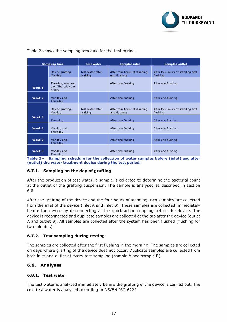
Table 2 shows the sampling schedule for the test period.
Sampling time Test water Samples inlet Samples outlet
Week 1
Day of grafting,
Monday
Test water after
grafting
After four hours of standing
and flushing
After four hours of standing and
flushing
Tuesday, Wednes-
day, Thursday and
Friday
After one flushing After one flushing
Week 2 Monday and
Thursday
After one flushing After one flushing
Week 3
Day of grafting,
Monday
Test water after
grafting
After four hours of standing
and flushing
After four hours of standing and
flushing
Thursday After one flushing After one flushing
Week 4 Monday and
Thursday
After one flushing After one flushing
Week 5 Monday and
Thursday
After one flushing After one flushing
Week 6 Monday and
Thursday
After one flushing After one flushing
Table 2 - Sampling schedule for the collection of water samples before (inlet) and after (outlet) the water treatment device during the test period.
6.7.1. Sampling on the day of grafting
After the production of test water, a sample is collected to determine the bacterial count
at the outlet of the grafting suspension. The sample is analysed as described in section
6.8.
After the grafting of the device and the four hours of standing, two samples are collected
from the inlet of the device (inlet A and inlet B). These samples are collected immediately
before the device by disconnecting at the quick-action coupling before the device. The
device is reconnected and duplicate samples are collected at the tap after the device (outlet
A and outlet B). All samples are collected after the system has been flushed (flushing for
two minutes).
6.7.2. Test sampling during testing
The samples are collected after the first flushing in the morning. The samples are collected
on days where grafting of the device does not occur. Duplicate samples are collected from
both inlet and outlet at every test sampling (sample A and sample B).
6.8. Analyses
6.8.1. Test water
The test water is analysed immediately before the grafting of the device is carried out. The
cold test water is analysed according to DS/EN ISO 6222.
18
6.8.2. Cold water samples
Samples of water collected during testing of devices for cold water must be analysed for
aerobic bacterial count in yeast extract agar by using the pour plate method as well as by
incubating at 22 C for three days and 37 C for two days according to DS/EN ISO 6222.
6.9. Acceptance requirements for cold water devices
The aerobic bacterial count at 22 C and 37 C (DS/EN ISO 6222) measured in water
drawn immediately after the water treatment device must be less than five times the
level of aerobic bacteria in the water from the distribution system measured at the in-
let of the water treatment device. However, a value of 10 times the content of the in-
let water measured immediately after grafting is acceptable.
The bacterial count at 37 C must not increase systematically or gradually over the
test period.
There must be no selection of the bacterial count at 22 C and 37 C towards a pure
culture at the end of the test period. This requirement is assessed on the basis of a
characterization of the bacterial flora, and if necessary an identification of the dominant
flora in the water that is led into the device as well as the processed water. This takes
place during week 6.

19
Table 3 shows the requirements, accept criteria and calculation methods for microbiological
testing of water treatment devices.
Requirements Calculation method Accept criteria
Co
ld w
ate
r d
evic
e
The aerobic bacterial count of the processed water is less than five times the level of aerobic bacteria in the inlet water. A value of 10 times the content of the inlet water measured im-mediately after both graft-ings is acceptable.
Ratio: outlet/inlet = The average of (A outlet + B out-let) divided by the average of (A inlet + B inlet) This is calculated for both the aer-obic bacterial count at 22 C and 37 C
Week 1: After grafting, day 1: Ratio: outlet/inlet <10 Other days: Ratio: outlet/inlet <5 Week 2: Ratio: outlet/inlet <5 Week 3 After grafting, day 1: Ratio: outlet/inlet <10 Thursday: Ratio: outlet/inlet <5 Week 4, 5 & 6: Ratio: outlet/inlet <5
Bacterial count determined at 37 C must not increase
systematically or gradually during the test period.
Ratio: 37/22 = The average of (A outlet 37 + B outlet 37) divided by the average of (A outlet 22 + B outlet 22)
The entire test period: Ratio: 37/22 <1,5
Table 3 – Requirements, accept criteria and calculation methods for microbiological testing of water treatment device.
6.10. Assessment of microbiological flora
An assessment of the microbiological flora should be made in connection with the samples
collected during week 6. A macroscopic and a microscopic examination of the emerged
bacterial flora should be carried out in connection with the water samples collected at the
inlet as well as after the water treatment device (outlet).
The composition of the bacterial flora must be described by extracting a minimum of five
representative colonies from water samples collected at the inlet as well as the outlet dur-
ing week 6.
This assessment of the bacterial flora must be accompanied by a conclusion to which the
requirement is that a shifting tendency of the bacterial flora before or after the water
treatment must not be detected. Moreover, there should be no sign that the flora, which
grows from the samples after the water treatment, is a pure culture.