Embed Size (px)
Citation preview

TEST EQUIPMENT ~ /NSTRUCT/ON
MANUAL

MODEL 630-PL & PLK
VOLT-OHM-MILLIAMMETER
One Triplett Drive Bluffton, Ohio 4581 7

SAFETY RULES Warning
This tester has been designed with your safety in mind. However, no design can completely protect against incorrect use. Electrical ~ircuits can be dangerous and/or lethal when lack of caution or poor safety practices are used.
Read The Manual Read this Instruction Manual carefully and completely. Voltages and currents within the capability of this test equipment can be
hazardous. Follow the instructions in this manual for every measurement. Read and understand the general instructions before attempting to use this tester. Do not exceed the limits of the tester.
Safely Cheek Double check the switch setting and lead connections ,before making
measurements. Are you following all of the instructions? , Disconnect the tester or turn off the power before changing switch positions. Do not connect to circuits with voltage present when switch is in any ohms or
current position. When replacing fuses use only specified type fuses and insert in correct fuse
holder. Don't Touch
Don't touch exposed wiring, connections or otherl"live" parts of an elec- trical circuit. If in doubt, check the circuit first for voltage before touching it.
Turn off the power to a circuit before connecting test probes to it. Be sure there is no voltage present before you touch the circuit.
Do not use cracked or broken test leads. High Voltage Is Dangerous
Always start with the power off. Be sure there is no voltage present before making connections to the circuit.
Don't touch the tester, its test leads, or any part of the circuit while it is on. Before disconnecting the tester, turn the circuit off and wait for the meter to
return to "zero." Distribution Circuits Pack A Punch !
In high energy circuits such as distribution transformers and bus bars, dangerous arcs of explosive nature can occur if the circuit is shorted. If the tester is connected across a high energy circuit when set to a low resistance range, a cur- rent range, or any other low impedance range, the circuit is virtually shorted.
Special equipment designed for use with these circuits is available. Contact a qualified person for assistance before attempting to make measurements on any high energy circuit.
Safety Is No Accident
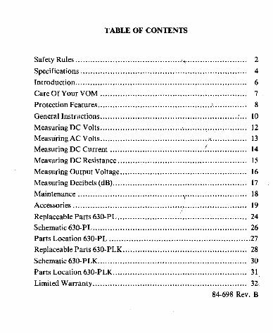
TABLE OF CONTENTS
............................................ ........................ Safety Rules , 2
Specifications ................................................................... 4
Introduction ..................................................................... 6
Care Of Your VOM ........................................................... 7
Protection Features .......................................... ....I .............. 8
General Instructions ........................................................... 10
Measuring DC Volts ............................................................ 12 . . . Measuring AC Volts ............................................................ 13
t Measuring DC Current ....................................................... 14
Measuring DC Resistance .................................................... 15
Measuring Output Voltage ................................................... 16
...................................................... Measuring Decibels (dB) 17
Maintenance .................................................................. 18
Accessories ...................................................................... 19
Replaceable Parts 630-PL .................................................... 24
Schematic 630.PL .................... ; ......................................... 26 Parts Location 630-PL ......................................................... 27 Replaceable Parts 630-PLK .................................................. 28
Schematic 630-PLK .......................................................... 30
Parts Location 630.PLK ...................................................... 31. Limited Warranty ........................................................... 32\
84-698 Rev . B

SPECIFICATIONS DC Volts
Ranges
Accuracy
Sensitivity
Maximum Input Voltage
AC Volts Ranges Accuracy
Sensitivity Maximum Input Voltage
DC Current
Ranges
Ohms Ranges
Accuracy
Maximum Voltage - Volts Maximum Current - niA Maximum Power Transfer
to Load - mW
I
0-250 Milliyplt, 0 - 2.5, 10, 50, 250, 1000
k 1 1/2% of Full Scale Reading (Calibrated at 77 OF (25 OC))
20,000 Ohms per Volt, 10,000 Ohms per Volt on a250 Millivolt
1000 Volts
0 - 3, 10, 50, 250, $boo 3% of Full Scale Reading
(Calibrated at 77 "F (25 OC))
5000 Ohms per Volt 1000 Volts RMS
0-100 Microamperes at 250 mV 0 - 10, 100, 1000 Milliamperes at 250 mV
0-10 Amperes at approx. 1 Volt (at end of test leads)
0 - 1000,10,000. . . 0 - lM, l00M (4.4 - 44,4400 - 440,000 at Center Scale)
+ 1 1 /2% of Full Scale Length
X1 XI0 XlK Xl00K 1.6 1.6 1.6 34 364 36.4 .364 .0773
150 75.0 .I50 .655
4
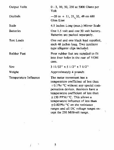
Output Volts
Decibels
Scale
Batteries
Test Leads
Rubber Feet
Size
Weight
Temperature Influence
0 - 3, 10, 50, 250 at 5000 Ohms per Volt
-20 to + 11, 21,L35, 49 on 600 Ohm Line
4.5 Inches Long ( m a ) Mirror Scale
One 1.5 volt and one 30 volt battery. Batteries are packed separately.
One red and one black lead supplied, each 48 inches long. Two insulator type alligator clips included.
Four rubber feet are supplied to fit into four holes in the rear of VOM case.
3 11/32" x 5 1/2" x 7 1/2"
Approximately 4 pounds >
The meter movement has a temperature coefficient of less than + 0.1 %/ OC without any special com- pensation devices. Resistors have a temperature coefficient of less than + 150 PPM/OC. This allows a temperature influence of less than + 0.0250/0/ OC on the resistance ranges and all DC voltage ranges ex- cept the 250 Millivolt range. ,

INTRODUCTION Your VOM is a compact, rugged, portable volt-ohm-milliammeter.
It has been designed to make fast, accurate measurements on all types of electrical and electronic equipment and is backed by a company which has been making quality instruments an'd test equipment for over half a century.
The indicating portion of the VOM is actuated by the latest concept in instrumentation, namely, a taut band suspension meter (shown below) having a sensitivity of 50 microampere full scale: This meter, by omitting conventional pivots, bearings and hairsprings provides the following advantages.
I. Increased repeatability by elimination of frihion between pivots and bearings.
spnsnrian Band
Lwf Tension Spring

2. Greater ruggedness and durability as no moving parts are in contact and the elimination of the hairspring prevents snag- ging and tangling. The tension spring acts as a built-in shock absorber.
3. Temperature variations can not cause sticky operation of the pointer.
Reference to the illustration will assist in understanding the princi- ple of operation. The moving coil floats in the magnet by virtue of the suspension bands which are held in tension by a spring. These bands, which are fabricated of a precious metal alloy, provide torque and carry the current to the moving coil. The moving coil a2sembly is held by a rigid one piece die cast frame in a large self-shielded "Bar Ring'' magnet.
1 CARE OF YOUR VOM
Although this instrument is portable and rugged it should be treated with care. Do not drop or handle it roughly.
Avoid placing it on a bench where machine tools are used or severe vibration is encountered.
When possible keep it in a place of moderate temperature. Avoid subjecting it to extreme temperatures and severe temperature changes.
If the VOM has not been used for a long period of time, rotate the selector switch in both directions several times to wipe the switch con- tacts for good contact.
Turn the selector switch to OFF when the VOM is to be carried. The meter is damped in the OFF position to prevent wild swinging of the pointer.

MODEL 630-PLK PROTECTION FEATURES
Your VOM is equipped with an overload protection circuit to pro- tect against overloads which normally would 'damage or destroy cir- cuit components and/or the meter. The protection circuit uses a tran- sistorized amplifier which controls a manually reset latching type relay. The amplifier senses the voltage across the meter terminals. When this voltage reaches four to six times the rated full scale meter voltage, the amplifier "fires" and energizes the relay. Smaller overloads not sufficient to make the amplifier "fire" will not cause damage to the instrument. The relay contacts, located in the VOM in- put circuit, latch open and remain open until the manual reset button (located to the right of the selector switch on the front panel) is depressed. b
In the normal operating condition (reset button in), the tran- sistorized protection amplifier draws negligible stand-by current (less than 1 microampere-the approximate shelf life drain on the 30 volt battery).
The overload protection feature is intended to guard against occa- sional human error, not to encourage careless instrument use. Par- ticular care should be exercised to prevent the application of voltages exceeding 100 volts to the current and low ohms ranges as the low im- pedance of these circuits may cause momentary surges of current beyond the capacity of the overload relay contacts. The fuse in the in- put circuit provides added protection for the relay contacts; under some conditions the fuse may blow in addition to the overload relay contacts opening.
All ranges are provided with protection to prevent damage as follows:
1. The 1 and 10 ampere ranges are protected by 1 and 10 ampere fuses respectively.
2. The inherent high resistance of the l00K ohm, 1000 Volt AC and DC range circuits limits current to a level which will not damage the instrument.
3, All other ranges are protected by the transistorized overload protection circuit previously described.
As an added protection to the meter, a silicon diode network prevents damage to the meter pointer by by-passing instantaneous transient voltages that might bend the meter pointer before the relay contacts open.

PRECAUTIONS The 30 volt ohmmeter battery must be installed and tested before
the VOM is placed in service since this battery is used in the overload protection circuit. After installing the batteries,'they should be tested as follows:
1. Turn the selector switch to the XlOOK position.
2. Short the test leads together.
3. Adjust the meter pointer to zero ohms with the bhms adjust control. If the pointer cannot be set at zero the 30 volt bakery should be replaced at once. DO NOT operate the VOM if the lOOK ohms range will not zero since the overload protector will not operate properly. I
This procedure should be repeated periodically to i n s u ~ proper operation of the overload protection circuits.

GENERAL INSTRUCTIONS The following section should be read carefully; it contains instruc-
tions and precautions to be observed in making measurements with the VOM.
h
Measurements are made with the test leads plugged into the COM - and V-R-A jacks, except when measuring output volts (dB). For these ranges the V-R-A test lead is plugged into the appropriate jack (one test lead is in the COM - jack for all measurements).
The insulated alligator clios orovided with the VOM fit over the end of the test probei. When measuring high voltages, the use of'these alligator clios will allow measurement without. handling the test oro- b e s y ~ s a safety measure, always shut off power source before attemp- ting to connect alligator clips.
/
Caution: If the VOM has been overloaded-disconnect the test probes from the power source before depressing the "reset" button.
When the approximate value of the quantity being measured is not known, always start on the highest range. For greatest accuracy, choose the range which will allow readings t o p taken in the upper (right hand) portion of the scale.
Readings are taken on the scale having the appropriate significant figures (both 2.5 and 250 volts are read on the 0-250 scale) by multiplying or dividing by a factor of 10 or 100 as indicated by the range scale ratio (i.e.; on the 2.5 volt range divide the scale readings by 100).
The polarity reversing switch reverses the polarity of the entire VOM at the input jacks. This allows fast switching in case of,wrong polarity; and also provides a convenient polarity reversal for ohms ranges, a very useful tool in semiconductor checking. The V-R-A jack ' is positive when the polarity switch is in the DC+-R-ACV position.
Whenever possible, the test probes should be disconnected from the voltage source (or the source shut off) before the range switch or polarity switch positions are changed. This practice will result in an in- creased life and reliability for the VOM.
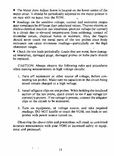
The Meter Zero Adjust Screw is located on the lower center of the meter cover. It should be periodically adjusted so the meter pointer is on zero with no input into the VOM.
Readings on the sensitive voltage, current and resistance ranges may sometimes be different than calculated values. Thermo-electric or electro-chemical reaction can sometimes generate voltage (or current) in a circuit due to elevated temperatures from soldering, contact of dissimilar metals, chemical fumes or moisture. Alsa, the fingers should never touch the metal parts of the test probes since ,body resistance can cause erroneous readings-particularly on the high ohmmeter ranges. , ,
Check the test leads periodcally. Leads that are worn', have damag- ed insulation, damaged plugs, damaged probes or lodse parts should be replaced.
CAUTION: Always observe the following rules and procedures when making measurements in high voltage circuits:
1. Turn off equipment or other source oP voltage, before con- necting test probes. Make sure no capacitors in the circuit being tested remain charged to a high voltage.
2. Install alligator clips on test probes. While holding the insulated section of the test probe, check circuit to see if any voltage (or current) is present. If no voltage is present, connect the alligator clips to the circuit to be measured.
3. Turn on equipment, or voltage source, and take required readings. DO NOT handle or touch the VOM, test leads or test probes with power source turned on.
Observing the above rules and precautions will result in continued accurate measurments with your VOM or increased safety to equip- ment and personnel.

MEASURING DC VOLTS 0-250 DC Millivolts:
1. Insert test leads in V-R-A and COM - jacks.
2. Place selector switch in 100 pA position.
3. Connect the test probes across the voltage to be measured as shown in Fig. 1.
4. Read DC millivolts on black "AC-DC" scale. '
0-2.5 thm 0-1000 DC Volts:
1. Insert test leads in V-R-A and COM - j'acks.
2. Place selector switch in appropriate DCV posiJion.
3. Connect the test probes across the voltage to be measured as shown in Fig. 1.
4. Read voltage on black "AC-DC" scale.
Fig. 1 Mcmuring DC Volts
12
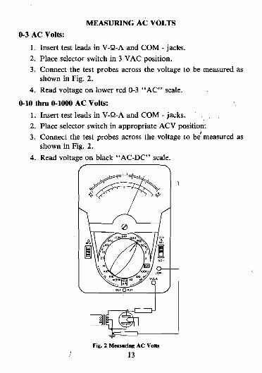
MEASURING AC VOLTS 0-3 AC Volts:
1. Insert test leads in V-R-A and COM - jacks. 2. Place selector switch in 3 VAC position. 3. Connect the test probes across the voltage to be measured as
shown in Fig. 2.
4. Read voltage on lower red 0-3 "AC" scale.
0-10 thru 0-1000 AC Volts:
1. Insert test leads in V-R-A and COM - jacks. 2. Place selector switch in appropriate ACV position! 3. Connect the test probes across the voltage to blmeasured as
shown in Fig. 2.
4. Read voltage on black "AC-DC" scale.
Fig. 2 Measuring AC Volts I 13

MEASURING DC CURRENT 0-100 pA thru 0-10 Amps:
1. Insert test leads in V-R-A and COM - jacks.
2. Place selector switch in appropriate position. 3. Connect the test probes in series with the circuit (use alligator
clips) as shown in Fig 3.
4. Read current on black "AC-DC" scale. In most cases, the voltage drop across the VOM on current ranges
will not affect the circuit being measured. However, in some 'low voltage transistor circuits it may be necessary to compensate the cir- cuit for the added voltage drop.
NOTE: The 1000 DCMA and 10A ranges are fused for overload protection. If the meter fails to indicate, a fuse may be blown. (See Fuse Replacement Section under "Maintenance.")
Fig. 3 Measuring DC Current
I 14

MEASURING DC RESISTANCE
X1 thru XlOOK Ohms Ranges: 1. Place selector switch in appropriate ohms range.
,, 2. Short test probes together.
3. Adjust "RADJ" control until meter reads zero ohms.
4. Connect test probes to component being measured.
5. Read ohms on top black "R" scale (multiply value read times range switch factor).
The component being measured should be disconnected f r o i the circuit before its resistance is measured since any added circuit path can cause an error in measurement. Also any voltage or current pre- sent in the circuit during measurement can cause an erfor in resistance measurement.
When using the ohmmeter for general continuity and circuit trac- ing it is recommended the X1K resistance range be used. The lower battery drain on this range (compared to the X1 range) will result in increased battery life.
Fig. 4 Measuring DC Resistance
15

MEASURING OUTPUT VOLTAGE
Output voltage is the AC part of a combine4 AC and DC voltage. Such a voltage is usually found in amplifier circuits, but it may also be found in other circuits. To measure output voltage, the DC part of the combined voltage must be removed or "blocked." This is done by in- serting a capacitor in series with the AC voltage section of the VOM. The VOM has a .I@ 400 VDC capacitor between the OUTPUT and V-R-A jacks to do this.
0-3 Volts (Figure 5): . . .,
1. Insert test leads into the OUTPUT and COM -,{acks. 2. Set the selector switch to 3 ACV position. 3. Connect test probes across the voltage to be measured. 4. Read voltage on the Red 0-3 "ACV" scale.
0-10 thru 0-250 Volts (Figure 5):
1. Insert test leads into the OUTPUT and COM - jacks. 2. Set selector switch to appropriate ACV range.
3. Connect test probes across the voltage to be measured. 4. Read voltage on "AC-DC" scale.
DO NOT USE THE OUTPUT range in circuits where the sum of the DC voltage and the peak AC voltage is greater than 400 volts.
The impedance of the capacitor is generally insignificant at audio frequencies. However, it may cause the meter to read low at low fre- quencies. Its effect should be considered in critical low frequency measurements.
WHEN THE VOLTAGE BEING MEASURED is AC with no DC present, the standard AC voltage measurement procedure should be used.
i 16

Fig. 5. Measuring Ovtput
MEASURING DECIBELS $dB)
The decibel is a unit that expresses the ratio of power levels. It is mathematically derived to reduce multiplication and division to ad- dition and subtraction, respectively, (e.g. - 10 dB represents multiplication by 10, 20 dB - 100, 30 dB - 1000). The decibel roughly approximates human hearing ratios. For this reason, it is commonly used in audio and telephone measurements.
Because the decibel represents a ratio, there is a reference level. The reference level for 0 dB is 1 milliwatt into a 600 ohm load (.775 ACV across 600 ohms). Measurements made across loads other than, 600 ohms are relative measurements.
To measure decibels, connect the VOM the same as for measuring AC voltage (or OUTPUT voltage, if there is DC voltage present). But, read the dB scale instead of the voltage scales. A chart on the dial shows the dB values to be added to the reading for the different voltage ranges. (e.g. - When the selector switch is set to the 50 VAC position, add 24 dB to the indicated value.) As explained above, addi- tion of dB represents multiplication of power (or voltage).
i 17

MAINTENANCE
Battery Replacement
Two batteries are used in the ohmmeter circuits.
A 1.5 volt battery, (size D NEDA 13F). 1s Gsed in the XI, X10, and XIK ranges. If the pointer cannot be adjusted to zero when the selec- tor switch is on one of these ranges and the test prods are touched together, the 1.5 volt battery should be replaced.
A 30 volt battery, NEDA 210, is used in the XlOOK range. The 30 volt battery should be replaced if the pointer cannot be adjusted to zero when the selector switch is on the XlOOK range and the test prods are touched together.
The 30 volt battery is also used in the overload protective circuit. This battery must be installed and in good condition or the overload protective circuit will not operate.
To replace the batteries, remove the four screws in the bottom of the case and lift the back up and off. Remove the old batteries and replace with new ones. Be careful to observe ~olar i ty as indicated on the battery compartment.
Fuse Replacement
Spare 1 amp and 10 amp fuses are supplied with this instrument and are stored in the bottom of the battery compartment. CAUTION: Use only the fuses supplied or identical fuses as listed in the parts list. The substitution of fuses of other types and values may not afford proper protection and may also disturb the accuracy of the meter.
Cleaning The Plastic Window The plastic window has been treated at the factory to dissipate
static charges that otherwise would attract the meter pointer and make it cling to the window.
If cleaning is required use cotton dipped in a solution o f household detergent and water. After cleaning allow the solution to dry without rubbing or polishing.
18 I

Parts Replacement Parts available for replacement are listed in the parts list. When
replacing any parts, be careful to not disturb or damage any others. Do not overheat resistors or diodes, but be sure to make a good solder connection. I
In some cases, it is wise to leave part of the lead from the old com- ponent and solder the new component to the old lead to prevent damage to surrounding components.
If there is evidence of smoke or an electrical arc inside the VOM, return the VOM to the factory or an authorized service center. There is a chance of hidden damage that could cause another failure in the VOM. Calibration
With normal use, readjustment of this VOM should not be necessary. Replacement parts are designed to be installed without any need for recalibration of the VOM. An occasional check of the VOM against a known reference voltage or another VOM is good practice. If there is a question about the accuracy of the VOM, it should be returned to the factory or an authorized service center for a calibra- tion check. ACCESSORIES ,
The usefulness and range of your VOM can be extended by the use of the following listed accessories.
High Voltage Measurement Accessory probes are available for measuring high voltages such as
found in television receivers and other equipment. To use these probes, plug the probe into the V-R-A jack, connect the black ground lead into the COM - jack, and set the selector switch to the position indicated below.
Use extreme caution in measuring high voltages-observe all the rules and precautions listed in the "General Instructions" regarding high voltage measurements.
Probe Set Part No. Selector Read o n Mult~ply Kilovolt Range Switch To, Range: By:

AC Current Measuring Adapter
AC line loads can be checked easily, withod breaking the conduc- tors or insulation of the circuit under test, when the Model 10 CLAMP-ON AMMETER ADAPTER (Cat. No. 60-21 1) is used. The Adapter is connected with a No. 61 1 LEAD ASSEMBLY (Part No. 79-415). The lever on the side of the Model 10 Adapter.is pressed to open the split yoke of the adapter so it can be placed over and closed around the lead or bus bar carrying the current being measured. Readings up to 300 AC amperes can be made.' , .,
MODEL 10 CLAMP-ON ADAPTER ,"
NO. 611 LEAD ASSEMBLY
Fig. 7. Model 10 Clamp-On Adspler

THE MODEL 101 LINE SEPARATOR (Cat. No. 60-218) is used to divide a circuit using two-conductor cable so one conductor can be encircled by the adapter yoke. The Model 101 is plugged into the AC outlet and the AC cord of the equipment to be measured is plugged into the appropriate socket on the Model 101. The split yoke of the Model 10 Adapter is clipped through the loop in the Model 101 to make the current measurement. Use of the "Divide by 10" and "Divide by 20" sockets on the Model 101 Line Separator makes a convenient and fast method of measuring extremely low AC current.
'
MODEL 10 CLAMP-ON ADAPTER PLUG INTO
Fig. 8. Model 101 Line Separator
Carrying Cases - ..
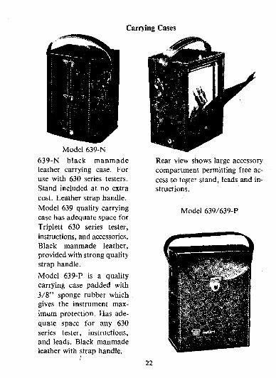
Model 639-N 639-N black manmade leather carrying case. For use with 630 series testers. Stand included at no extra cost. Leather strap handle. Model 639 quality carrying case has adequate space for Triplett 630 series tester, instructions, and accessories. Black manmade leather, provided with strong quality strap handle.
Model 639-P is a quality carrying case padded with 3/8" sponge rubber which gives the instrument max- imum protection. Has ade- quate space for any 630 series tester, instructions, and leads. Black manmade leather with strap handle.
Rear view shows large accessory compartment permitting free ac- cess to te,ster stand, leads and in- structions.
Model 639/639-P

Carrying Case
Model 639-0s

MODEL 630-PL TYPE 6 REPLACEABLE PARTS
Ref. No. Description P& Number Battery 30V
(NEDA 210) Battery 1.5V
(NEDA 13F) Capacitor .1pF 400V Fuse 10 Amp 250V Fuse 1 1/4 Amp
250V Meter VOM Front Resistor 3.75 Meg Resistor 1 Meg Resistor 200k Resistor 35k Resistor 5000R Resistor 5000R Resistor .25R Resistor 2.5R Resistor 25.12R Resistor 50009 Resistor 423 k Resistor 13.6k Resistor 4690R Resistor 37.257 Resistor 3.7'2 Resistor 73257 Resistor 6.5R Resistor 45k Resistor 150k Resistor 800k Resistor 4 Meg Resistor 7.5 Meg Resistor 7.5 Meg Not Used 24

Ref. No. Description Part Number
R29, R30 R3 1 SWI
SW2 CRAl CRIA, CRlB
RADJ Control 20k 16-31 Shunt Assembly 10 ' a
AMP 90-1036 Not used Resistor 5100R 15R-512JC Switch 22-319 Switch, with Resistors 22-585 ' Switch, Slide 22-152 Rectifier Assem. 2250-30 Diode Assembly Meter
Protect 127-114 , Knob Red, with Spring 34-62 Case with Handle 10-784 Test Leads 79- 127
Repair or Service For repair of the VOM, return it to the factory or an authorized
service center. To help in repairing the VOM, give a detailed descrip- tion of the problem and any other data that might be helpful such as what kind of circuit was being measured when the problem was discovered.
If the VOM is damaged by an o,ferload and there is evidence of smoke or an electrical arc inside, return it to the factory or an authorized service center for inspection and repair. There could be some hidden damage that would cause a future failure of the VOM.

Schematic 6WPL

8 1
82
CRI
F 2
R l 2
R I I R I O
R 9 ,
R 3 1
R 8
R 7
R 6
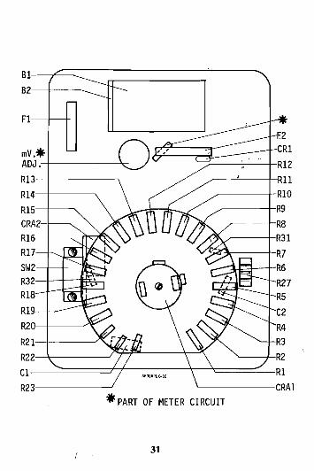
Parts Location 630-PL

84-698 REV C
'I
MODEL 630-PLK TYPE 9 REPLACEABLE PARTS
Ref. No. Description Part Number Battery 30V
(NEDA 210) Battery 1.5V
(NEDA 13F) Capacitor .1pF 400V Capacitor 10pF 50V Fuse 10 Amp 250V Fuse 1 Amp 125V Meter VOM Front Resistor 3.75 Meg Resistor 1 Meg Resistor 200K Resistor 35k Resistor 5000R Resistor 5000S2 Resistor .25R Resistor 2.5R Resistor 25.12R Resistor 5000R Resistor 860052 Resistor 423 k Resistor 73252 Resistor 6.5R Resistor .15R Resistor 37.252 Resistor 469052 Resistor 45k Resistor 150k Resistor 800k Resistor 4 Meg Resistor 7.5 Meg Resistor 7.5 Meg Not used

Ref. No. Description Part Number
R27 RADJ Control 20k 16-31 R28 Shunt Assembly ' L
lOAMP 90-1037 R29, R30 Not used R3 1 Resistor 5 100R 15R-512JC R32 Resistor 3.66R 15-5898 SWl Switch 22-466 .
Switch, with Resistors 22-584 SW2 Switch, Slide 22-152 CRAl Rectifier Assem. 2250-30 CRl Diode Assembly Meter
I Protection 11670
CRA2 Overload Protection Circuit Board 87-1054
Knob Red, with Spring 34-62 Case with Handle 10-784 Test Leads 79-127 Pushbutton 62-7 Spring 42-232
Repair or Service For repair of the VOM, return it to the factory or an authorized
service center. To help in repairing the VOM, give a detailed descrip- tion of the problem and any other data that might be helpfu1,such as what kind of circuit was being measured when the problem wass discovered.
If the VOM is damaged by an overload and there is evidence of smoke or an electrical arc inside, return it to the factory or an authorized service center for inspection and repair. There could be some hidden damage that would cause a future failure of the VOM.

SWI SELECTOR SWITCH SHOWN INPOSITION
NO. I (1000ACV)

LIMITED WARRANTY % a The Triplett Corporation warrants instruments and test equipment manufactured by it
to be free from defective material or factory workmanship and agrees to repair or replace such products which, under normal use and service, disclose the defect to be the fault of our manufacturing, with no charge for parts and service. If we are unable to repair or replace the product, we will makc a refund of the purchase price. Consult the Instruction Manual for instructions regarding the proper use and servicing of instruments and test equipment. Our obligation undcr this warranty is limited to repairing, replacing or daking refund on any instrument or tcst equipment which proves to be defcctive within three years (on? year guaranteed calibration) from the datc of original purchase.
This warranty does not apply to any of our products which have been.,repaired or altered by unauthorized persons in any way so as, in our sole judgment, to injure their stability or reliability, or which have becn subject to misuse, abus,;: misapplication, ncgligence or accidcnt or which have had the serial numbers altered, defaced, or removed. Accessories, including batteries and fuses, not of our manufacturc used with this product are not covercd by this warranty.
To rcgister a claim under the provisions of this warranty, return the instrument or test equipment to Triplett Corporation, Bluffton, Ohio 45817, transportation prepaid. Upon our inspection of the product, we will advise you as to thc disposition of your claim.
ALL WARRANTIES IMPLIED BY LAW ARE HEREBY LIMITED TO A PERIOD OF THREE YEARS, AND THE PROVISIONS OF THE WARRANTY ARE EXPRESS- LY IN LIEU OF ANY OTHER WARRANTIES EXPRESSED OR IMPLIED.
The purchaser agrees to assume all liability for any damages and bodily injury which mav result from the use or misusc of the oroduct bv the ourcharer. his emolovees. or others, and the remedies provided for in this warranty are &pressly in lieu o i any other liability Triplett Corporation may have, including incidental or consequential damages.
Some statcs (USA only) do not allow the exclusion or limitation of incidental or conse- quential damages. so the above limitation or exclusion may not apply to you. No represen- tative of Triolett Corooration or any other oerson is authorized to extend the liabilitv o f Triplctt Corporation in connection with the sale of its products bcyond the terms hereof.
Triplctt Corporation rcscrves thc right to discontinue modcls at any time, or'change specifications, price or design, without notice and without incurring any obligation. '
This warranty gives you specific legal rights, and you may have other rights which vary from state to state.
TRIPLETT CORPORATION Bluffton, Ohio 45817

m CORPORA770N Quality andTechnobgy for Tomorrow ONE TRIPLE77 DRIVE, BLUFFTON, OH 4581 7 (419) 358-5015 1-800-874-7538 FAX (419) 358-7956