Embed Size (px)
Citation preview

Terms Used by Power System Protection Engineers PREPARED BY THE Power System Relaying Committee Relay Standards Subcommittee Power System Engineers Working Group
IEEE Power & Energy Society
Jul 1997 TECHNICAL REPORT
PES-TR8 Formerly TP130
© IEEE 2013 The Institute of Electrical and Electronic Engineers, Inc. No part of this publication may be reproduced in any form, in an electronic retrieval system or otherwise, without the prior written permission of the publisher.

THIS PAGE LEFT BLANK INTENTIONALLY

Terms Used by Power System Protection Engineers
A Special Publication of theIEEE
Power System Relaying Oommittee
•~\)\"EEIIJ4'q~
~ ~C). ~~ -<
IEEt
Prepared by theTerms Used by Power System Engineers Working Group
of theRelay Standards Subcommittee
1997-July-31

Terms Used by Power System Protection Engineers
This special report was prepared for and approved by the "Power System Relaying Committee" of the "IEEE Power Engi-neering Society". It was prepared by the "Terms Used by Power System Engineers Working Group" of the "Relaying Stan-dards Subcommittee".
At the time of its approval, January 1997, the Working Group Membership was
M.S. Sachdev, ChairDepartment of Electrical Engineering
University of Saskatchewan57 Campus Drive
SASKATOON SKCanada S7N 5A9
B.D. Nelson, Vice ChairWisconsin Power and Light222 W. Washington Avenue
MADISONWI 53703
Bajpai, M., Phoenix, AZBeckwith, B.L., Lavina, MTClough, G.K., Vancouver, WADalke, G.R., Edmond, OKDarlington, A.N., Tampa, FL
Elmore, W.A., Coral Springs, FLlIar, F., Baden, SwitzerlandPlumptre, F.P., Vancouver, BCWiedman, T.E., Chicago, ILWhittaker, J., London, UKZugris, D., Washington, DC
Abstracting is permitted with credit to the source. For other copying, reprint, or republication permission, write to theIEEE Copyright Manager, IEEE Operations Center, 445 Hoes Lane, Piscataway, NJ 08855-1331. All rights reserved.Copyright © 1998 by The Institute of Electrical and Electronics Engineers, Inc.
IEEE Catalog Number: TP130-0-031998-1-0
Additional copies of this publication are available from
IEEE Operations CenterP. O. Box 1331445 Hoes LanePiscataway, NJ 08855-1331 USA
1-800-678-IEEE (IndividuallMember Orders)1-800-701-IEEE (Institutional Orders)1-732-981-00601-732-981-9667 (FAX)email: [email protected]

Foreword
Members of the "Power System Relaying Committee"have expressed concern from time to time that recentlygraduated engineers, technologists and engineers fromother disciplines usually experience difficulty with prop-erly interpreting the terminology used in the area of PowerSystem Protection. The consequence is that they experi-ence difficulty in communicating effectively with theircolleagues.
To overcome this difficulty, the "Power System RelayingCommittee" of the IEEE formed, in January 1991, the"Terms Used by Power System Protection EngineersWorking Group". This working group was assigned thetask of preparing a special publication which should de-scribe in a straight forward manner the terms commonlyused by power system protection engineers.
Almost all the terms, discussed in this report, are definedin the IEEE Std 100-1992 "The New IEEE Dictionary ofElectrical and Electronics Terms", the "International Elec-trotechnical Commission's" publication, "IEC Multilin-gual Dictionary of Electricity" and standards published byvarious organizations. The objective of the report was notto redefine the terms but provide brief explanations to as-sist the recent graduate engineers, technologists and new
entrants in the area of power system protection in under-standing them properly.
To keep the explanations from conflicting with the defmi-tions of terms provided in the standards, the WorkingGroup maintained liaison with the "Terminology UsageReview Working Group" (of the "Relay Standards Sub-committee" of the "Power System Relaying Committee"of the IEEE "Power Engineering Society") that recom-mends adoption of new definitions for inclusion in theIEEE dictionary and IEEE/ANSI standards.
The explanations of the terms were written and then re-vised several times to avoid conflict with the official defi-nitions and to make the explanations suitable for achievingthe intended objectives of this report. The Working Grouphopes that this document will be found useful by recentengineering graduates, technologists, and engineers whodo not have formal training in Power System Protectionbut have to interact with protection engineers.
M.S. SachdevWorking Group Chair
- iii -
Terms Used by Power System Protection EngineersCopyrightCO The Instituteof Electrical and Electronics Engineers, Inc.

Table of Contents
Working Group Membership............ ii 5.1 Distance Relay ..................... 13Foreword.................................... iii 5.2 Impedance Relay ...................... 13Table of Contents........................... iv 5.3 Mho Relay ......................... 14List of Figures................................... v 5.4 Blinder.............................. 15
1. Introduction.............................. 16. Other Relays............................. 16
6.1 Differential Relays ................ 162. General Terms........................... 2 6.1.1 Transformer differential
2.1 Accuracy........................... 2 protection.................... 172.2 Accuracy Class .................... 2 6.1.2 Magnetizing inrush currents 17
2.3 Reliability............................. 2 6.2 Other Relays for Transformer
2.3.1 Dependability.............. 3 Protection.......................... 18
2.3.2 Security..................... 3 6.2.1 Combustible gas relay ...... 18
2.4 Sensitivity.......................... 3 6.2.2 Gas accumulation relay .... 18
2.5 Relay Stability..................... 3 6.2.3 Static pressure relay ........ 18
2.6 Primary Protection................ 3 6.2.4 Sudden pressure relay ...... 18
2.7 Backup Protection................ 3 6.3 Thermal Relay ..................... 18
2.8 Dual Protection..................... 3 6.4 Temperature Relay ............... 18
2.9 Device Number................... 3 6.4.1 Replica Relay or replicatemperature relay .......... 19
3. Relay Types............................... 5 6.4.2 RTD Relay ................... 203.1 Relay ................................ 5 6.5 Loss of field (excitation) Relay. 203.2 Electromagnetic Relay ............ 5 6.6 Out-of-step Relay ................. 203.3 Electromechanical Relay .......... 53.4 Solid-state and Static Relay...... 6 7. Circuit Breaker Applications......... 21
3.5 Microprocessor-based Relay .... 6 7.1 Breaker Failure ..................... 21
3.5.1 Multi-function Relay ........ 7 7.2 Poie Disagreement................ 227.3 Pole Flashover..................... 22
4. Overcurrent Relay....................... 9 7.4 Single-Pole Tripping............. 224.1 Instantaneous Overcurrent Relay 94.2 Overcurrent Relay Time-Current 8. System Disturbances................... 23
Characteristic...................... 9 8.1 Underfrequency Relay ............ 234.2.1 Time dial, (Time lever, Time 9. Disturbance Analysis..................... 24
multiplier).................. 9 9.1 Sequential Events Recorder....... 244.3 Directional Overcurrent. .............. 10 9.2 Transient Fault Recorder.......... 24
4.3.1 Connection angle ........... 11 9.2 Pre-fault, Fault and Post-fault4.3.2 Polarizing quantity .......... 11 Periods .............................. 24
5. Ohmic Relay Applications............ 13 Bibliography..................................... 25
- iv -Terms Used by Power System Protection Engineers
Copyright © The Institute of Electrical and Electronics Engineers, Inc.

List of Figures
Fig.No.
1.
2.
3.
4.
5.
6.
7.
8.
9.
9.
10.
11.
12.
Title of Figure Page
A line protected by a current re-lay......................................... 2
An Electromagnetic (current operated)plunger relay. .. ... ... ... .. . . . . . .... 6
Block diagram of a microprocessor-based relay. . . . . . . . . . . . . . . . . . . . . . . . .. . . .. . 7
Signal and data flow of a microproc-essor based relay 0 • • • • • 8
Time current characteristics com-monly used in inverse time overcur-rent relays , " 9
Electrical and mechanical arrange-ment of a typical inverse time over-current relay....................... ..... 10
Impact of time dial adjustment on theoperating time of an overcurrent re-lay......................................... 10
Voltage phasors used in 60° and 90°connection angles..................... 12
(a) Phase and polarizing voltages, andphase currents during normal opera-tion ,., 12
(b) Phase currents and polarizing volt-ages for identifying the direction of aphase-b to phase-c fault. 12
"Zones of protection" of relays pro-tecting a transmission line... . . . . . . . . . 13
Generally used characteristics of ge-neric distance relays... . . . .. . .. . . .. . . . .. . 14
Operating characteristics of imped-ance and offset impedance relays.. ... ,. 15
Fig.No.
13.
14.
15.
16.
17.
18.
19.
20.
21.
22.
23.
24.
25.
26.
Title of Figure Page
Typical operating characteristic of amho relay......... 15
A typical current differential re-lay.......................................... 16
A typical percentage differential re-lay......................................... 16
Zero sequence currents in a delta-wyetransformer.......................... 17
Typical magnetizing inrush currents ina delta-wye transformer.............. 18
Mounting and schematic arrangementof a sudden pressure relay... 19
Thermal relay monitors 12R losses inthe protected equipment... . . . . . . . . . . . . 19
The mounting of a typical temperaturerelay...... 19
The circuit diagram of a replica re-lay........................................ 20
Circuit ofa typical RTD relay....... 20
Single bus switching arrangement;circuit breaker A fails to interrupt cur-rent.................................... 21
A breaker-and-a-half switching ar-rangement; circuit breaker A fails tointerrupt current to fault on the line tocircuit breaker J.. . .. . . . . . . . . . .. .. .. ... 21
Circuit breaker failure in a ring busswitching station....................... 22
Contact arrangement of the a threephase circuit breaker which has twopoles per phase.. 22
- v -
Terms Used by Power System Protection EngineersCopyright o The Institute of Electrical and Electronics Engineers, Inc.

1. INTRODUCTION
There is considerable concern among power system engi-neers in general, and power system protection engineers inparticular, that recent graduates and engineers from otherdisciplines usually experience difficulty with properlyinterpreting the terminology used in applying relays, ana-lyzing their performance and designing protection sys-tems.
This makes it difficult for relay engineers to communicateeffectively with their colleagues and convey their inter-pretations of relaying issues and questions effectively. Toovercome this difficulty, the "Power System RelayingCommittee" of the IEEE "Power Engineering Society"decided to prepare a special publication that would pro-vide, in simple and straightforward language, interpreta-tions of the terms used in the area of power system pro-tection. The "Terms Used by Power System ProtectionEngineers Working Group" was formed in January 1991and was assigned the task of preparing a special publica-tion describing the terms commonly used by power systemprotection engineers.
The Working Group appreciated at the outset that defini-tions of almost all the terms used by power system protec-tion engineers are included in the IEEE Std 100-1992"The New IEEE Dictionary of Electrical and ElectronicsTerms" [2], the "International Electrotechnical Commis-sion's" publication, "IEC Multilingual Dictionary of Elec-tricity" [9] and standards published by various organiza-tions.
The Working Group discussed and decided
• neither to redefme the terms already included in thedictionaries and standards,
• nor to reproduce the established definitions fromstandards, and also
• not to provide historical development of terms.
The Working Group decided to provide, in its special re-port, explanations of the terms in a straight forward man-ner so that recent graduate engineers, technologists andnew entrants in the area of power system protection canunderstand them properly and become useful participantsin their work without unnecessary frustration.
- 1 -Terms Used by Power System Protection Engineers
Copyright © The Institute of Electrical and Electronics Engineers, Inc.

2. GENERAL TERMS
Figure 1. A line protected by a current relay.
2.3 Reliability
Fault
12,000 A
---+
Ct Ratio 600/5
Ct secondarycurrent> IOOA
---+
2.3.1 Dependability
Dependability is the aspect of reliability that expresses thedegree of certainty that a relay will operate correctly. Forrelay systems, dependability is assured by using redundantprotection systems and backup relays.
Example: The primary protection for a transmis-sion line may be provided by using a phase comparisonprotection scheme. The degree of certainty that thisscheme will operate for all faults on the transmissionline is the dependability index of the scheme. To in-crease this index for the transmission line protection
Reliability is an index that expresses the attribute of aprotective relay or a system to operate correctly for situa-tions in which it is designed to operate. This also includesthe attribute of not operating (incorrectly) for all othersituations. Reliability is expressed in terms of two com-peting fundamental attributes, dependability and security.
2.2 Accuracy Class
This term is used to define the quality of the steady stateperformance of a current transformer. The accuracy classof a current transformer (ct) used for protection functionsis described by a letter which indicates whether the accu-racy can be calculated (class C) or it must be obtainedfrom physical tests (class T). This letter is followed by anumber which is equal to the maximum secondary tenni-nal voltage that the ct will produce at 20 times the ratedsecondary current with no more than 10% error.
Examples of accuracy classes for 10% error class C cts areCIOO, C200, C400 and C800. At this time, there is noaccuracy class higher than C800. Examples of accuracyclasses for 10% error class T cts are TI05, 1250, T375and T750.
• accuracy,
• accuracy class,
• reliability,
• security,
• dependability,
• sensitivity,
• relay stability,
• primary protection,
• backup protection,
• dual protection, and
• device number.
2.1 Accuracy
This term is used for at least two different purposes, one todescribe the accuracy of a device and the other to specifythe accuracy of a measurement.
In the first context, accuracy is the degree to which a de-vice (relay, instrument or meter) conforms to an acceptedstandard. The statement of an accuracy is only as good asthe methods used to express it for individual componentsand the manner in which they affect the overall accuracyof the device.
In the second case, the accuracy of a measurement speci-fies the difference between the measured and true valuesof a quantity. The deviation from the true value is theindication of how accurately a reading has been taken or asetting has been made.
Example: If a relay is specified to have ±5% accu-racy, it means that the relay should operate when itsexciting quantity (current or voltage) is between -5%and +5% of its setting.
Let us consider the case of Figure 1 and assume thatthe ct provides secondary current which is an accuraterepresentation of the primary current. When the faultcurrent is12,000 A, the current in the relay will be100 A. If the relay accuracy is ±5%, it could interpretthe current to be of any level from 95 A to 105 A. Incase the relay is set to operate at 100 A, it mayor maynot operate depending on its interpretation of the levelof current in the circuit.
The terms concerning the quality of measurements andphilosophy of protection are described in this section. Thespecific terms included in this section are
- 2 -
Terms Usedby PowerSystem Protection EngineersCopyright (Q The Instituteof Electrical and Electronics Engineers, Inc.
system, distance relays can be included to act asbackup relays.
2.3.2 Security
Security is the aspect of reliability that expresses the de-gree of certainty that a relay will not operate incorrectly
irrespective of the nature of the operating state of thepower system.
Example: If a differential relay is designed to operatefor faults in a transformer it is protecting, the degree ofcertainty that the relay will not operate for faults out-side the transformer zone is the security index of therelay.
2.4 Sensitivity
This term is used to express different attributes of devices.One definition expresses it as a ratio of the response of thedevice to the change of the input. In the power systemprotection field, sensitivity is the minimum value of aninput (or change of an input) that would cause a relay tooperate.
Example: An instantaneous ground fault directionalrelay designed to operate at a minimum current of O.5Awould be classified as having a sensitivity of 0.5 A.
2.5 Relay Stability
A relay is considered to be stable if, starting from a steadystate, it returns to the same steady state following the in-troduction and removal of inputs representing a distur-bance in the system to which it is connected.
Example: A solid-state timing relay, whose timing ac-curacy is not affected by the changes in the dc voltagesupply used to operate it, is considered to be stable.
Example: Consider that a relay system experiences amomentary loss of de supply used for performing logicand/or tripping functions. If the relay system returns toa normal steady state mode on restoration of the desupply, the relay is considered to be stable.
Stability differs from security. A stable but insecure pilotrelay system may trip incorrectly due to a weakness in thetripping logic or design. A secure but unstable pilot relaysystem may experience wide variations in the input andoutput levels but will not trip incorrectly.
2.6 Primary Protection
The protection system that is designed to operate beforeother devices respond to a disturbance due to its sensitivityand speed, is said to provide primary protection.
Example: A differential relay protecting a transformeris expected to operate when a fault is experienced in itsprotection zone. Other devices used to protect thetransformer, such as overcurrent relays, are expected tooperate if the differential relay fails to detect the fault.In this case, the differential relay provides primaryprotection for faults in its zone of protection.
2.7 Backup Protection
Relays used to provide second line of defense are said toprovide backup protection. The operating time of theserelays is longer than the operating time of primary relays,and, therefore, they operate but trip appropriate circuitbreakers only if the primary relays fail to detect the pres-ence of the disturbance or fail to open the circuit breakers.These relays could be physically in the substation in whichthe primary relays are located or may be located in a re-mote substation.
Example: A phase comparison system can be used toprovide primary protection of a transmission line.Distance relays may be used, without permissive over-reach or transfer trip, to provide backup protection ofthe line.
2.8 Dual Protection
Power system equipment of bulk transmission systems isoften protected with dual primary relays. Both primaryprotection systems are kept independent of each other asfar as possible. Depending on the protection philosophyadopted, each protection system may be connected to itsown cts, vts, relays, trip coils of circuit breakers and bat-teries. These systems are sometimes referred to as "Pro-tection system A" and "Protection system B".
Example: A transmission line may be protected by adifferential protection system, which is expected to op-erate in 10 to 15 ms, and a distance protection systemwith transfer trip, which is also expected to operate incomparable time. The differential protection in thiscase could be classified as "Protection system A" or"Protection system 1" and the distance protection sys-tem could be classified as "Protection system B" or"Protection system 2."
2.9 Device Number
The circuit diagrams used in power systems use nomen-clatures and device numbers as specified in theANSI/IEEE Standard C37.2. A device number is assignedfor each type of relay and instrument. The phases areidentified as A, B, C or a, b, c. The numerals 1, 2 and 3are not used because I is used to identify positive se-
- 3 -Terms Used by Power System Protection Engineers
Copyright ~ The Institute of Electrical and Electronics Engineers, Inc.
quence quantities and 2 is used to identify negative se-quence quantities.
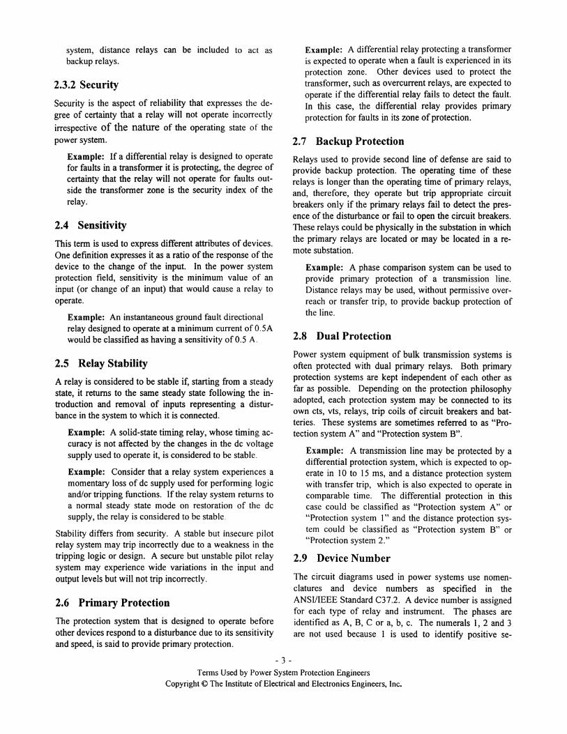
Examples: Some of the device numbers specified inthe Standard are listedin the following table.
Device AssignedNumber
Distance relay 21Undervoltage relay 27Instantaneous overcurrent relay 50Ac time overcurrent relay 51Overvoltage relay 59Ac directional overcurrent relay 67Frequency relay 81Differential relay 87
- 4-TermsUsedby PowerSystemProtectionEngineers
CopyrightCO The Instituteof Electrical and ElectronicsEngineers, Inc.

3. RELAY TYPES
This section briefly describes the following terms used fordescribing different types of relays.
• Relay• Electromagnetic relay• Electromechanical relay• Solid-state and static relays• Microprocessor-based relay
3.1 Relay
A relay is a device which operates when the input providedto it exceeds (or decreases below) a specified level andother specified conditions are met. The relay may open orclose an electrical contact directly, or indirectly by operat-ing another relay. Electromagnetic, electromechanical,analog electronic, digital electronic, or a combination ofthese technologies, are used in manufacturing them.
The operation of any protection relay is based on compari-sons of perceived values, calculated from the inputs, withpre-specified limits for operation. The following tableillustrates the characteristic values compared in differenttechnologies.
Technology Comparison of
Electromechanical Electromagnetic forcesSolid-state Electrical signalsDigital Numerically processed quan-
tized samples
Example: Overcurrent relay, directional relay, differ-ential relay, distance relay, frequency relay and under-voltage relay are a few examples of relays used in elec-tric power systems.
Example: An overcurrent relay may be designed tooperate when the current applied to it exceeds a speci-fied level and remains above that level for a pre-specified time.
3.2 Electromagnetic Relay
An electromagnetic relay is a device which uses electro-magnetic energy, directly or indirectly, to operate. Theoperation of the relay may close some of its contacts whileopening the remaining contacts. These contacts are used inexternal circuits energizing or de-energizing those circuits.
Most electromagnetic relays use one of the following phe-nomena.
• Electromagnetic attraction (or repulsion)• Electromagnetic induction
• Magnetic amplification
The phenomena of electromagnetic attraction (or repul-sion) and electromagnetic induction are used to causephysical movement of parts of a relay causing the relaycontacts to open or close.
A magnetic amplifier relay usually has an ac and a de coil(or two ac coils) on a magnetic core. Interaction betweenthe fields generated by the two coils can be used to com-pare either the levels of two inputs or the relative phaseangle between the inputs. These devices can also be de-signed to amplify input signals of small levels.
3.3 Electromechanical Relay
An electromechanical relay is a device which has one ormore mechanical parts that move when current flow in itselectrical circuit exceeds a specified level. Typical elec-tromechanical relays used for power system protection arebased on the principle of electromagnetic attraction (orrepulsion) or electromagnetic induction.
A typical electromagnetic attraction relay is shown in Fig-ure 2. When the electromagnetic force generated by theflow of current (ac or de) in its electrical circuit exceedsthe force of the restraining spring and the gravitationalforce on the plunger, the plunger moves. The shorting barmounted on the plunger bridges the output contacts caus-ing current to flow in that circuit. Several variations ofsuch relays are used in power system protection applica-tions.
In an electromagnetic induction relay, ac current flowing inthe relay produces a flux which generates eddy currents inits rotor which can either be a disc or a cup. The interac-tion between the magnetic flux and the eddy currents gen-erates a force which tries to rotate the disk. The disk isfree to rotate but is restrained by a spring. When the forcegenerated by induction exceeds the restraining force of thespring, electrical contacts attached to the rotor move tobridge stationary contacts. For more details, see overcur-rent relays, and time-dial / time-lever / time-multiplier sec-tions.
- 5 -Terms Used by Power System Protection Engineers
Copyright (g The Institute of Electrical and Electronics Engineers, Inc.

During digital processing, high frequency components canappear to belong to the fundamental frequency class. Thisphenomenon is referred to as aliasing. To prevent aliasingfrom affecting the relaying functions, anti-aliasing filtersare used along with the analog input isolation block.
galvanic isolation for the relay from the power system,reduces the level of the input voltages, converts currents toequivalent voltages and removes high frequency compo-nents from the signals using analog filters. Other relayscould be monitoring temperature, pressure, flow and otherparameters. The outputs of the analog input subsystem areapplied to the analog interface, which includes amplifiers,multiplexers and analog-to-digital (AID) converters. Thesecomponents sample the reduced level signals and converttheir analog levels to equivalent digital numbers which arestored in memory. The status of switches and circuitbreakers in the power system is provided to the relay viathe digital input subsystem and are read into the micro-computer memory.
The acquired information is processed by a relaying algo-rithm, which is a part of the software. The algorithm usessignal processing techniques to measure magnitudes andphase angles of voltages and currents. In some cases, thefrequency of the system is also measured. These meas-urements are used to calculate other quantities, such asimpedances. The computed quantities are compared withpre-specified thresholds (settings) to decide whether thepower system is experiencing a fault or not. If it is, therelay sends a command to open one or more circuit break-ers for isolating the faulted zone of the power system. Thetrip output is transmitted to the power system through thedigital output subsystem.
The software, relay settings and other vital information arestored in non-volatile memory of the relay. Random-access memory (RAM) is used for storing data temporar-ily. The power supply to a relaying microcomputer mustbe available even when the system supply is interrupted.Arrangements are, therefore, made to provide energy to therelay during normal and abnormal operating conditions ofthe power system.
Sometimes, these relays are called numerical relays spe-cifically if they calculate the algorithm numerically. Thesignal and data flows in these relays are shown in Figure 4.The relay is isolated from the power system by using aux-iliary transformers which receive analog signals and reducetheir levels to make them suitable for use in the microproc-essor- based relay. Since the analog to digital converterscan handle voltages only, the currents are passed throughshunts to convert them to voltages proportional to the cur-rents.
ContactOutput
up
1-----.I
Figure 2. An Electromagnetic (current operated)plunger relay.
A solid-state or static relay uses semi-conductor technol-ogy to perform its intended functions. It may also usemagnetic or optical elements.
Sometimes a distinction is made between solid-state relaysand static relays. Relays with solid-state output circuits areclassified as solid-state relays. A static relay may have anelectromechanical relay to energize the trip circuit.
Microprocessor relays, which utilize semi-conductor com-ponents, have a special defmition reserved for them; theyare not referred to as solid-state relays. For more detailsof those relays refer to the sections on microprocessor re-lays, digital relays and numerical relays.
3.5 Microprocessor-based Relay
Early relays for power system protection used electrome-chanical technology which was later supplemented bysolid-state electronics. A large number of electromechani-cal and solid-state relays are in operation at this time. Withthe advent of digital processing technology, designersstarted to use microprocessors in relay designs. These re-lays are now marketed by several manufacturers.
Figure 3 shows an example of the block diagram of a mi-croprocessor-based relay. This relay monitors voltages andcurrents, which, at the power system level, are in the rangeof hundreds of kilo volts and kilo amperes respectively.The levels of these signals are reduced by vts and cts typi-cally to 67 V and 5 A nominal values.
The outputs of the vts and cts are applied to the analoginput subsystem of the relay. This subsystem provides
- 6 -Terms Used by Power System Protection Engineers
Copyright <0 The Institute of Electrical and Electronics Engineers, Inc.
3.4 Solid-state and Static Relay

After being quantized by the AID converter, analog electri-cal signals are described by discrete values of the samplestaken at specified instants of time. These discrete numbersare processed by using numerical methods. For example,quantized values of current and voltage samples may beused to estimate the magnitudes and phase angles of theirpha-sors. Voltage and current phasors may be further usedto calculate impedances as seen from a relay location.
The digital signals are applied to the relay via optic isola-tors which insure physical disconnection of the relay fromthe power system.
3.5.1 Multi-function relay
Microprocessor relays were initially developed to replacethe existing single-function relays. For example, separaterelays were used to perform differential, loss of field, over-current and unbalanced loading protections of generators.During the past few years, relays that perform more thantwo protective functions have been developed. These areclassified as multi-function relays.
POWER. SYSTEM
cts & vts
,rAnalog Input
Subsystem"Digital Input
Subsystem
Digital OutputSubsystem
AnalogInterface
,rMicro-
processor
IRAM ROM
Control
PowerSupply
MICRO-COMPUTER
Communication
RELAY
Figure 3. Block diagram of a microprocessor-based relay.
- 7 -
Terms Used by Power System Protection EngineersCopyright o The Institute of Electrical and Electronics Engineers, Inc.

Analog Input Low pass Sample Multi- AIDIsolation Shunt Filter Amplifier and Hold plexer Conversion
1'1 * -{>- Analog toAI S/H MUX AID Digital
Converson
DigitalFilters Numerical
COM MMI Signal
*Z<
~Processing
I>etc. Serial
Com m unicationFault/Event
Binary Input Trip Recording Binary OutputIsolation Algorithm PLC Isolation Binary
Processing AR Signaletc.
~Processing
BI V~k DO
Logic FunctionProcessing
Figure 4. Signal and data flow of a microprocessor-based relay.
- 8-TermsUsedby PowerSystemProtection Engineers
Copyright~ The Instituteof Electrical and Electronics Engineers, Inc.

4. OVERCURRENT RELAY
4.2.1 Time dial (Time lever, Time multiplier)
Figure 7 shows how the operating time of a relay changeswhen the time dial setting is changed from 0.5 to 7.
The time dial (also referred to as time lever or time multi-plier) is the means for controlling the operating time of therelay. This is achieved by changing the angle throughwhich the disk must rotate before its contacts are closed.Since the moving contact travels in an arc, it can be length-ened or shortened by selecting an appropriate time dialsetting. The adjustment of the arc is calibrated in the formof an index which is known as the time dial.
\~ Extremely inverse
Very inverse
current •
Time current characteristics commonlyused in inverse time overcurrent relays.
CI)
E;
t
Figure 5.
air gap of an electro-magnet which is excited by currentflowing in its coil. The current in the coil produces flux inthe air gap. Because the current in the coil is alternating innature, the flux in the air gap is also time varying. Theflux induces eddy currents in the disk. The air gap fluxand the eddy currents interact with each other producing atorque that tries to rotate the disk. Since the disk is heldback with a spring, it does not start to rotate until thetorque exceeds a specified level.
A moving contact, which is attached to the shaft, as well asa stationary contact are provided in the relay. The coil ofthe electromagnet is provided with taps which allows therelay engineers to change the effective turns on the elec-tromagnet. These settings are used to select the pickupcurrent of the relay.
• inverse time,• very inverse time,• extremely inverse time, and• definite minimum time.
Inverse time overcurrent relays (device number 51), oper-ate when the current in the relay exceeds a threshold. In-verse time delay means that the higher the relay current,the lower is the operating time. Some of the commonlyused time delay characteristics are
4.2 Overcurrent Relay Time-CurrentCharacteristic
Sample current-time characteristics are shown in Figure 5.These curves represent the operating time of the relaywithin specified tolerance. Notice that the definite mini-mum time characteristic has approximately constant timedelay for relay currents larger than three times the setvalue. Relay engineers use these curves, that are publishedby the manufacturers, to predict the time the relay wouldtake to operate for different levels of relay current.An induction disk inverse time overcurrent relay is shownin Figure 6. It has a non-magnetic disk, usually made ofaluminum, mounted on a shaft. The disk is placed in the
4.1 Instantaneous Overcurrent Relay
This type of relay has been assigned by ANSI the devicenumber 50. The term instantaneous has at least twomeanings and functions. The first concerns the operationof a relay or the tripping of a circuit breaker. It means thatno intentional time delay is added to the trip function. Therelay operates when it detects that the current level hasexceeded the threshold setting. These relays operate typi-cally in 4 to 16 ms on a 60 Hz system. The second func-tion concerns the reclosing of circuit breakers. In thiscontext, it means that reclosing of a circuit breaker is notintentionally delayed after it has been tripped. There is,however, an inherent albeit small time delay in performingthese functions.
• instantaneous overcurrent relay,• inverse time overcurrent relay,• directional overcurrent relay,• time dial (time lever, time multiplier),• connection angle, and• polarizing quantity.
The terms used in the area of overcurrent relay are de-scribed in this section. These include
- 9 -Terms Used by Power System Protection Engineers
Copyright o The Institute of Electrical and Electronics Engineers, Inc.

~-1IllIIo... Time Dial - only dial6 numbers 6-9 shown
Stationary
cont~
~~ingContact
Disk rotor,
C.T.
Figure 6. Electrical and mechanical arrangement of a typical inverse time overcurrent relay.
relay location. This is sometimes not desirable. For ex-ample, in a line of a network, fault currents at a relay loca-tion could be flowing for faults on the line side of the relayas well as for faults on the bus side of the relay. A lineprotection relay must be restrained from operating forfaults on the bus side of the relay.
Directional overcurrent relays are used in such situations.These relays (classified as device number 67), when de-signed with electromechanical or analog electronic tech-nologies, consist of an overcurrent element supervised by adirectional element. The overcurrent element respondsonly if the fault is in the specified direction.
Some directional relay applications use single-phase direc-tional relays; one relay is applied in each phase of thethree-phase power system. Another application is forground directional protection, which use ground (or resid-ual current) and the sum of the three phase voltages (orcurrent in the neutral connection of the source).
In the phase directional relays, the phase angle of the cur-rent with respect to the voltage is checked. In the grounddirectional relays, the phase angle of the ground or residualcurrent is checked with respect to the phase angle of thesum of the three-phase voltages. Alternatively, the phase
0.5
Time dial
7
10 100 1000
CURRENT-A ---+
Overcurrent relays respond to currents during faults expe-rienced on the power system in either direction from the
4.3 Directional Overcurrent
Figure 7. Impact of time dial adjustment on the oper-ating time of an overcurrent relay.
- 10 -TermsUsedby PowerSystemProtection Engineers
Copyright© The Institute of Electrical and Electronics Engineers, Inc.

angle of the residual current is checked with respect to aneutral current of a source that provides a constant refer-ence no matter where the fault is located.
4.3.1 Connection angle
In the phase directional relays, the phase angle between thecurrent and voltage is used to decide if the fault is in theforward direction. Different combinations of currents andvoltages can be used for this comparison. Consider thatthe three directional relays are applied currents fromphases A, B and C. Two of the several options for select-ing the voltages for use in these relays are listed in Table 1.
In Option 1, the voltage element of the relay, which re-ceives phase A current, is applied voltage from phase C.As shown in Figure 8, unity power factor load currentleads the applied voltage by 60°. This is also true for therelays which receive phase B and phase C currents usingconnections of Option 1. The relays which use this combi-nation of currents and voltages are identified as having aconnection angle of 60°.
Similarly, when connections of Option 2 are used, the re-lay, which receives phase A current, is applied the voltagefrom phase B minus the voltage from phase C. In thiscase, the unity power factor current leads the applied volt-age by 90°. This is also true for the relays that receivephase B and phase C currents. The relays using this com-bination of currents and voltages are identified as having aconnection angle of 90°. The phasor diagram for thissituation is also shown in Figure 8. The polarizing voltage,Vb-Vc, and fault current for phase A to ground fault. la' arealso shown in this figure. Notice that the phase displace-ment between the fault current and the polarizing voltage isless than 30°.
The voltages, which are referred to as polarizing voltages,are selected in such a manner that they remain relativelyunchanged during a fault. This ensures that during systemfaults, when the currents have substantial magnitudes, thepolarizing voltages are as close to the nominal value aspossible.
Example: Consider that directional relays using Op-tion 2 for connecting the voltage elements have beenapplied at a relay location. Figure 9 (a) shows thephase voltages, Va' Vb and Vc' and the currents I, , I,and I, when the system is operating normally. Thepolarizing voltages (Vb-Vc ' v.v, and Va-Vb) and thecurrents during normal operation are also shown in thisfigure. Now consider that a phase A to phase B faulthas occurred on the line side of the relay and the fault isvery close to the relay location. The voltages and cur-rents for this situation are shown in Figure 9 (b). No-tice that the current I, leads the polarizing voltage (Ve-
VJ by a small angle, from 10° to 30°. Also, the currentI, leads the polarizing voltage (Va-Vc) by a small angle.This ensures that the relays sense that the fault is in theforward direction.
4.3.2 Polarizing quantity
Many relays use a voltage or current as a reference forcomparing their operating signal. This quantity has a pre-dictable phasor relationship to the current flowing to afault, irrespective of the location of the fault. The refer-ence voltage or current is referred to as the polarizing sig-nal.
Example: A healthy phase voltage, in addition to thefaulted phase voltage, is sometimes used in a relay as apolarizing voltage to assist in accurately determiningthe direction of the fault. This helps in correctly iden-tifying the direction of the fault especially when themagnitude of the faulted phase voltage is small. If afault, between phase b and phase c is experienced veryclose to the relay location, the phase b to phase c volt-age collapses. The phase voltages for this situation andthe currents are shown in Figure 9 (b). The polarizingvoltages and fault currents are also shown in this fig-ure. It is obvious from this figure that even if the phaseb and phase c voltages have collapsed to low values, thepolarizing voltages are substantial to ensure relay op-eration.
Table 1. Voltage and current combinations for 60° and 90° connections for directional relays.
Relay 1 Relay 2 Relay 3
Current applied
I~:Vc I~:v. I~~VbVoltage applied Option 1Voltage applied Option 2
- 11 -Terms Used by Power System Protection Engineers
Copyright <0 The Institute of Electrical and Electronics Engineers, Inc.

9cP ConnectionPhase A Fault
Vc Vc
Va I~ I a Va\
\
~ I bVb Vpo1= -Vc Vb
y
6cP Connection Vpo1= 'b-Vc
9cP Connection
Figure 8. Voltage phasors used in 60° and 90° connection angles.
v -Vc a
V -Vb c
V -Va b
Phase voltages andcurrentsduring normal operation
Polarizing voltages andcurrentsduring normal operation
Figure 9 (a). Phase and polarizing voltages, and phase currents during normal operation.
Phase voltages andcurrentsfora twophase fault close to
the relay location
Phase B current andthe
polarizing voltage Vc-Va
Phase C current andthe
polarizing voltage Va-Vb
Figure 9 (b). Phase currents and polarizing voltages for identifying the direction of a phase-b to phase-c fault.
- 12 -Terms Usedby PowerSystemProtectionEngineers
CopyrightC The Instituteof Electrical and Electronics Engineers, Inc.

5. OHMIC RELAY APPLICATIONS
5.2 Impedance Relay
Relays that respond to the magnitude of the measured im-pedance are classified as impedance relays. The measure-ment is taken by determining the ratio of the rms voltage ofthe line at the relay location to the rms current flowing inthe line at the relay location. These relays are commonlyapplied to detect faults on transmission lines. A compari-son of the measured impedance with the line impedanceprovides an indication whether the fault is in the protectedzone of the relay or not. This type of relay is also assigneda device number of21.
predominantly resistive. But, during faults, this impedanceis lower and highly reactive in nature. A change in thedetected impedance is used to determine if a fault has oc-curred, and also if the fault is in its zone of protection or iselsewhere on the system. This is accomplished by limitingthe operation of the relay to a certain range of the observedimpedance, commonly called, "reach." When a fault oc-curs within the protected zone of a distance relay protect-ing an end to end line, only the faulted transmission line isisolated.
The operating characteristics of these relays are expressedin terms of impedance or its components, resistance andreactance. Plotted on a rectangular coordinate system,(using resistance, R, as the abscissa and reactance, X, asthe ordinate) the characteristics usually form simple geo-metric figures. Commonly used operating characteristicsare shown in Figure 11. The point of measurement for adistance relay is located at the origin of the figures, and therelay is designed to generally operate when the measuredimpedance falls within the shaded area in the figures.
The major advantage of using a distance relay for multi-phase faults, not involving ground, is that its zone of op-eration is a function of only the impedance of the protectedline and the fault resistance (except for the situations whenthere is current in-feed from the remote terminal of the lineor there is mutual coupling with lines on the same right ofway). This is approximately a fixed constant, irrespectiveof the levels of fault current magnitudes. Therefore, a dis-tance relay has a fixed reach, as opposed to an overcurrentrelay whose reach varies as the system operating condi-tions change. Consequently, it is not necessary to changethe settings of distance relays unless the line characteristicschange. This makes distance relays ideally suited for pri-mary and backup protection for faults on transmissionlines.
Bus 2
Location of
jaYBRelay A Reach
~lZone of Protection of Relay A I
-----nZ .1I
t--_---- Z I1 Transmission Line I II~ nZ-----1 Zone of Protecuon of Relay 8I"Relay BReach
distance relay,impedance relay,mho relay, andBlinder.
BuslYLocation ofRelay A
Figure 10. Protection zones for relays protecting atransmission line.
The impedance measured during normal operation of a lineis the ratio of the voltage at the line terminal and the cur-rent flowing in the line; this value is usually high and is
- 13 -
5.1 Distance Relay
Faults on transmission lines are commonly detected byprotective relays that measure and respond to one or an-other form of the ratio of voltage to current. This ratio isimpedance or a component of impedance. These relays aretermed distance relays because (ideally) the measured im-pedance is proportional to the distance along a homogene-ous transmission line from the relay location to the fault.This class of relays is assigned device number 21.
The portion of line that is being protected by a distancerelay is called the "zone of protection" or the "protectedzone." Figure 10 shows that the zone of protection of Re-lay A, installed at bus 1, is from the relay location to a lo-cation close to bus 2. Similarly, the zone of protection ofRelay B, installed at bus 2, is from the relay location to alocation close to bus 1. If the line impedance is Z, thereach of each relay is nZ; n ranging from 0.75 to 0.90 insome applications, and more than 1.0 in some others.
•
•
••
This class of relays was originally used to protect transmis-sion lines and were believed to measure the distance fromthe relay location to a fault. Currently, several types areapplied to power systems for protecting lines during faults,generators during loss of excitation, and the system duringpower swings. The terms most commonly used and de-scribed in this section are
Terms Usedby PowerSystem Protection EngineersCopyright o The Institute of Electrical and Electronics Engineers, Inc.

jX Line Impedance
R
jX Line Impedance
Restraint
MaximumSensitivity Angle
R
Impedance CharacteristicMho Characteristic- Forward Reach
jX
Restraint
R
Offset Mho Characteristic- Forward Reach
jX
Restraint
R
Reverse Offset MhoCharacteristic
Figure 11. Generally used characteristics of generic distance relays.
power crossing the air gap being less than the load on theshaft, which is a function of the supply voltage and itsphase displacement from the voltage of the receiving sys-tem.
Mho Relay5.3
The operating characteristics of the impedance relay, andthe "reach," plotted on a rectangular coordinate system, isshown in Figure 12. Since an impedance relay responds tomeasurements in all quadrants, a directional unit is gener-ally used to limit the reach to the line side of the relay, as isshown in this figure. With this combination, the impedancerelay responds only to the measured impedances which are
Distance relays can be designed to have circular operatingin the shaded portion of this diagram.
characteristics, plotted on an impedance plane, that passesA variation of the impedance relays, called "offset imped- through the origin of the plane as shown in Figure 13. Thisance relays," whose characteristic is also shown in Figure type of relay is called a Mho relay or Admittance relay. A12, are used to start power line carrier protection. These fraction n of the line impedance ZL is a measure of dis-relays look from the circuit breaker towards the line as well tance of the fault on the line from the relay location. Theas the station bus. In addition, impedance relays can be Mho relay is inherently directional ; that is, it will "see"used to protect generators and transmission lines from out- and, therefore, respond only to transmission line faults inof-step conditions. On generators, this condition is due to one direction from the relay location. Maximum torque
- 14-Terms Used by Power System Protection Engineers
Copyright © The Institute of Electrical and Electronics Engineers, Inc.

angle is the impedance angle at which the relay is mostsensitive.
5.4 Blinder
Sometimes transmission lines are heavily loaded . Thepower being transmitted is such that the voltage to currentratio (apparent impedance) at the line terminal is less than
jX Line Impedance
Restraint
MaximumSensitivity Angle
R
Operating characteristicof an impedance and a
directional relay
the reach of the third zone setting of the line protectionrelays. A distance relay which has a straight-line non-directional characteristic is used to block the line relayfrom tripping during normal operation of the line. Thecharacteristic takes advantage of the fact that the apparentimpedance is predominantly resistive. The typical charac-teristic ofa blinder is shown in Figure 13.
R
Figure 12. Operating characteristics of impedance and offset impedance relays.
jX Line Impedance
Maximum Torque Line
Restraint
MaximumSensitivity Angle
R
Mho Characteristic- Forward Reach
jX
Blinder Characteristic
Restraint
R
Figure 13. Typical operating characteristic of a mho relay and a blinder.
- 15 -Terms Used by Power System Protection Engineers
Copyright © The Institute of Electricaland ElectronicsEngineers, Inc.
6. OTHER RELAYS
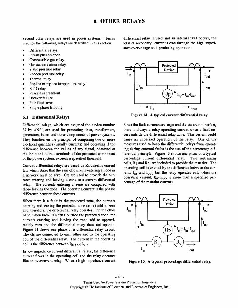
differential relay is used and an internal fault occurs, thetotal ct secondary current flows through the high imped-ance overvoltage coil, producing operation.
Several other relays are used in power systems. Termsused for the following relays are described in this section.
• Differential relays
• Inrush phenomenon
• Combustible gas relay
• Gas accumulation relay
• Static pressure relay
• Sudden pressure relay
• Thermal relay
• Replica or replica temperature relay
• RTD relay
• Phase disagreement
• Breaker failure
• Pole flash-over
• Single phase tripping
---.I.In
---. I-In
Protected ...._..,......~..__Device
---. Iout
Figure 14. A typical current differential relay.
---.Iout
j I =1.-1op In out
Protected t--..,....~...--Device
---.I.In
I I.t In
---.I-In
Figure 15. A typical percentage differential relay.
Since the fault currents are large and the cts are not perfect,there is always a relay operating current when a fault oc-curs outside the differential relay zone. This current couldcause an undesired operation of the relay. One of themeasures used to keep the differential relays from operat-ing during external faults is the use of the percentage dif-ferential principle. Figure 15 shows one phase of a typicalpercentage current differential relay. Two restrainingcoils, R1 and R2, are included to provide the restraint. Theoperating coil is excited by the difference between the cur-rents lin and lout, but the relay operates only when theoperating current, lin-lout, is more than a specified per-centage of the restraint currents.
6.1 Differential Relays
Differential relays, which are assigned the device number87 by ANSI, are used for protecting lines, transformers,generators, buses and other components of power systems.They function on the principal of comparing two or moreelectrical quantities (usually currents) and operating if thedifference between the values of any signal, observed atthe input and output terminals of the protected componentof the power system, exceeds a specified threshold.
Current differential relays are based on Kirchhoffs currentlaw which states that the sum of currents entering a node ina network must be zero. Cts are used to provide the cur-rents entering and leaving a zone to a current differentialrelay. The currents entering a zone are compared withthose leaving the zone. The operating current is the phasordifference between these currents.
When there is a fault in the protected zone, the currentsentering and leaving the protected zone do not add to zeroand, therefore, the differential relay operates. On the otherhand, when there is a fault outside the protected zone, thecurrents entering and leaving the zone add to approxi-mately zero and the differential relay does not operate.Figure 14 shows one phase of a differential relay circuit.The cts are connected to each other and to the operatingcoil of the differential relay. The current in the operatingcoil is the difference between lin and lout.
In low impedance current differential relays, the differencecurrent flows in the operating coil and the relay operateslike an overcurrent relay. When a high impedance current
- 16 -TermsUsedby PowerSystem Protection Engineers
Copyright (0 The Institute of Electrical and Electronics Engineers, Inc.

No 10 flow Singleline-to-groundfault
Figure 16. Zero-sequence currents in a delta-wyetransformer.
6.1.2 Magnetizing inrush currents
When a transformer is disconnected from the system andthe flow of current is interrupted, the transformer core re-tains a residual flux. The next time the transformer is en-ergized, the core may saturate and, therefore, draw largemagnetizing currents from the source even if no load isconnected to the transformer. Since the magnetizing cur-rent is supplied by the source and is not reflected on theoutput side of the transformer, it shows up as operatingcurrent in the differential relay circuit. Therefore, the relaymust be restrained from operating for this current.
The waveforms of magnetizing inrush currents are not si-nusoids of a single frequency; they contain substantialamounts of harmonics. Figure 17 shows two examples ofthe magnetizing inrush currents flowing into a delta wind-ing of a delta-wye transformer. These currents decay overa period of time, which depends on the size and type of thetransformer and the nature of the system.
The phase shift matching can also be achieved (incorrectly)by connecting the wye-side cts in wye and delta-side cts indelta. This arrangement would not compensate for thezero-sequence currents that would flow in the wye-connected winding and not in the delta-connected winding.In the arrangement of Figure 16, zero-sequence currentsflow in the wye-connected winding but circulate in thedelta winding when a single phase to ground fault on thesystem connected to the wye winding of the transformer isexperienced. The outputs of the cts provided on the deltaside do not contain the zero-sequence currents. The solu-tion is to eliminate the zero-sequence currents from theoutputs of the cts connected to the wye connected winding.This can be done by using a zero-sequence shunt (or trap)or by connecting the ct secondaries in delta, which alsosolves the phase shift problem described above.
6.1.1 Transformer differential protection
The ratio of the cts provided at the two terminals of theprotected zone and the differences in their characteristicsare always of concern in most applications. When differ-ential relays are used to protect transformers, the issuesthat are given special consideration include
• matching of ct ratios and performance,• phase shift due to transformer winding interconnec-tions,• elimination of zero sequence currents, and• transformer inrush.
The volt-amperes at the primary and secondary terminalsof a two-winding transformer are equal if the magnetizingcurrents are negligible. If a transformer steps up the pri-mary voltage to a higher level, the current at the high volt-age terminal is proportionately reduced. Selection of ap-propriate ct ratios is used to match the magnitudes of thecurrents entering and leaving the protected zone as appliedto the relay.
The connections of the windings of the protected trans-former may introduce a phase shift. For example, a trans-former with the high-side winding connected in delta andthe low-side winding connected in wye, would shift thephase angle of the low-side current by 30°. To compensatefor this phase shift, the cts of the wye side are connected indelta and cts outside the delta winding are connected inwye.
Example: Consider a three-phase 100 MVA delta-wye 13.8/230 kV transformer. The nominal currents onthe 13.8 kV and 230 kV sides are
100 *1000.;. (13.8 *~) = 4,184 A
100 *1000.;. (230 *~) = 251 A
If the primary cts are of 5,000/5 ratio and the secondarycts are of 400/5 ratio, the outputs of the primary andsecondary cts will be 4.18 A and 3.14 A respectively,when the transformer is supplying rated current.
Since cts on the wye-side of the transformer are connectedin delta, the outputs applied to the relay by the secondarycts will be 3.14*"3 = 5.43 A. The difference between the4.18 A current from the primary cts and 5.43 A currentfrom the secondary cts is eliminated by using ratio match-ing cts provided in the relays (or installed outside the relay)or taps provided on the relay. In some microprocessorrelays, this is achieved by including a multiplier in the re-lay software.
- 17 -Terms Used by PowerSystem Protection Engineers
Copyright© The Institute of Electrical and Electronics Engineers, Inc.

101,--- ----,- ----,-----,----.-- ---,----,-----,
2O',-------,-----.----..------r----.---,---~ portion of the gas released by the protected equipment. Itoperates when the volume of gas reaches a certain level.The accumulator relay can only be applied to transformerswith conservator tanks . Another name for this device is agas detection relay .
6.2.3 Static pressure relay
This relay (assigned the device number 71) can be used onall types of oil-immersed transformers. It is mounted be-low the oil level on the transformer tank wall and is acti-vated by the pressure in the tank . Because of the manyincorrect operations of the static pressure relays over theyears, most have been superseded by sudden pressure re-lays.
,ao120100eo 00'm,oe.,..20(a>
!5
~ 011--------"
jl<
~ -5
6.3 Thermal Relay
A thermal relay, (assigned device number 49) operates ifthe heat developed within the relay as a result of externaland internal conditions exceeds a specified level. The re-lay uses input(s) from ct(s) to monitor the 12R heating inthe protected equipment. This relay is different from atemperature relay which uses a temperature sensing device,either in or on the equipment being monitored. The circuitof a typical thermal relay is shown in Figure 19.
6.2.4 Sudden pressure relay
Two types of sudden pressure relays (assigned devicenumber 63) generally used to protect transformers are thesudden gas pressure and sudden oil pressure relays.
Sudden gas pressure relays operate if the rate of rise ofpressure in the transformer exceeds a specified level.These relays can be applied on all gas cushioned oil-immersed transformers and are mounted in the gas spaceabove the oil.
Sudden oil pressure relays measure the rate of rise of oilpressure and operate if it exceeds a specified value. Theserelays can be applied on all oil-immersed transformers andare usually mounted near the bottom of the transformertank wall.
These relays are commonly used to protect transformersand are generally connected to trip circuit breakers to dis-connect the transformer from the rest of the power system.Because the micro-switch contacts used in sudden pressurerelays are sensitive to control circuit disturbances, an aux-iliary relay is often included in the sudden pressure circuit.
120'00eo 00TlWE-'"
20(b)
Figure 17. Typical magnetizing inrush currents in adelta-wye transformer.
6.2 Other Relays for Transformer Protection
Other relays generally used for transformer protection in-clude
• combustible gas relay,• gas accumulation relay,• static pressure relay,• sudden pressure relay,• thermal replica relay ,• RTD relay,• loss-of-field (excitation) relay, and• out-of-step relay.
These relays are briefly described in this section .
6.2.1 Combustible gas relay
The combustible gas relay is applied to transformers whichare equipped with positive pressure inert gas-oil preserva-tion systems. This device measures the presence of com-bustible gas in the transformer in the inert gas blanket. Thepresence of the combustible gas indicates the decomposi-tion of insulating materials due to faults or corona. Sincethese faults are not accompanied with large fault currents,they are usually not detected by other relays until they de-velop into major short circuits which usually cause sub-stantial damage. The combustible gas relay is expensiveand is not normally applied on substation transformers.
.'OIO!----=----f;;---~-__.;;---___,;il-____,;O-_;:,40
6.2.2 Gas accumulation relay
Commonly known as a Buchholz relay, the gas accumula-tion relay is constructed so that it accumulates all or a fixed
6.4 Temperature Relay
A temperature relay (assigned device number 49) measuresthe external temperature of the protected equipment.
- 18-TermsUsedby Power SystemProtectionEngineers
Copyright<I} The Instituteof Electrical and Electronics Engineers, Inc.

Monitoring of the temperature is accomplished by using anRTD, gas bulb, thermocouple or another temperaturesensing device located at the point to be monitored. Themounting of a typical temperature relay is shown in Figure20.
6.4.1 Replica relay or replica temperaturerelay
These relays (assigned device number 49) are designed toachieve an internal temperature rise proportional to the
temperature rise of the protected apparatus, or conductor,over a range of values. A current proportional to the cur-rent in the protected equipment is passed through a heatingelement in the relay. The relay is designed to simulate theheating and cooling of the protected apparatus. The mod-eling of the cooling of the equipment is essential to protectthe equipment from being returned to service too soon aftera thermal overload. A typical circuit for a replica relay isshown in Figure 21.
Transformertank wall
Tripcircuit Micro-switch
Bellows Enlargedview . - - . - ~
Sudden / .....
pressure relayT ransformer tank
Sealedchambermounted ontheoutsideof the tankwall
Equalizingorifice
Simplified scheme fora sudden gaspressure relay Sudden gaspressure relay mounting onthesideof a transformer above theoil level
Figure 18. Mounting and schematic arrangement of a sudden gas pressure relay.
ElectricalSource
ThermalRelay
To protected!monitored equipment Electrical Source to Equipment
Figure 19. Thermal relay monitors IZR losses in theprotected equipment.
Figure 20. The mounting of a typical temperature re-lay.
- 19 -Terms Used by Power System Protection Engineers
Copyright © The Institute of Electrical andElectronics Engineers, Inc.

Figure 22. Circuit of a typical RTD relay.
Figure 21. The circuit diagram of a replica relay.
6.6 Out-or-step Relay
When two or more interconnected synchronous generatorsor systems have lost synchronism with respect to one an-other and are operating at different frequencies, they aresaid to be operating under an out-of-step condition. Thiscondition can be caused by a mismatch between the elec-trical output of the generator and the mechanical input tothe generator. Distance relays (in conjunction with blind-ers) are applied to detect and trip the generators when thisis suspected to have happened. Generally, the protection isdesigned either to trip the generator breaker or to open theline interconnecting the two systems. The disconnectedgenerator, or the interconnecting line are brought back inservice after the condition has stabilized. The out-of-steprelays are assigned the device number 78.
of the system experiencing a disturbance, the magneticfield must be changed to maintain the system voltage (at ornear the generator terminals) at the nominal value.
The excitation system can be supplied current from anauxiliary generator mounted on the shaft of the main tur-bine-generator unit, or from the plant auxiliary bus, or themain generator. Several circumstances can result in loss-of-field; these include
• accidental tripping of the field circuit breaker,• poor brush contact in the slip rings of the rotor, and• loss of ac supply to the excitation system.
Reduced levels of excitation, or complete loss of field canresult in loss of synchronism, instability and, possibly,damage to the generator. When a disturbance is experi-enced, the generator output oscillates (accompanied withrotor oscillations) in an attempt to stay in synchronous op-eration with the system. If the disturbance is accompaniedby a substantial decrease in the terminal voltage, systemstability is threatened. For these reasons, a loss-of-fieldrelay is applied to protect the generator and the system towhich it is connected. The relay is usually designed to tripthe generator when the relationship between the alternatingvoltages and currents, measured at the generator terminals,indicates that a loss-of-field condition has occurred. ANSIhas assigned device number 40 to loss-of-field relays.
Resistororheat source
Bi-metal
To protected!monitored equipment
ElectricalSource
MonitoredEquipment
6.5 Loss-or-field (excitation) Relay
The magnetic field is set up in a generator by providing dccurrents to the field winding of the generator. In the event
To~Power
SUP~--I----~--t_'
6.4.2 RTD relay
A temperature relay, assigned device number 49, uses aresistance temperature detector (RTO) to monitor the tem-perature of the protected equipment. An RTO is a resistormade of a material whose resistance changes in a prede-termined manner when the temperature changes. Electro-mechanical RTD relays normally use a Wheatstone bridge(or an equivalent circuit) to sense the temperature changesand respond with a predetermined output. One form ofmicroprocessor RTD relay applies a low level of current tothe resistor and measures the voltage drop across the re-sistor. From this measurement, it calculates the resistanceand the temperature. The electrical circuit of a RTD relayis shown in Figure 22.
- 20-Terms Usedby PowerSystemProtection Engineers
CopyrightC The Instituteof Electrical and Electronics Engineers, Inc.

7. CIRCUIT BREAKER APPLICATIONS
Circuit breaker A fails tointerrupt the fault current
A few terms concerning circuit breakers often used byprotection engineers are
• breaker failure,• phase disagreement,• pole flashover, or• single-phase tripping.
These terms are briefly described in this section.
7.1 Breaker Failure
B c D
The failure of a circuit breaker to interrupt fault currentfollowing the attempt to energize its trip coil by a protec-tive relay is described as breaker failure. The reason forsuch failures include
• inadequate or damaged interrupter,• mechanically damaged mechanism, and• lack of electrical continuity of the trip circuit.
A breaker failure relay (assigned device number 50BF)recognizes the condition of current continuing to flow inthe circuit breaker after a reasonable period of time haselapsed since a relay made an attempt to energize the tripcoil of the circuit breaker. On recognizing such a condi-tion, the breaker failure relay initiates the clearing of all thecircuits that can feed current to the fault via the failedbreaker.
The following three examples show the circuit breakersthat are tripped by a breaker failure relay.
Example: Circuit breaker A of a single bus switchingstation, shown in Figure 23, has failed to interrupt cur-rent flowing to a fault on the line it controls. The con-dition is identified by the breaker failure relay which is-sues commands to trip circuit breakers B, C and D. Therelay also issues a trip command to trip circuit breakerA.
Example: Circuit breaker A of the switching station,shown in Figure 24, has failed to interrupt currentflowing to a fault on line to circuit breaker J at the re-mote station. Circuit breakers Band J have success-fully interrupted the flow of current through them. Ondetecting circuit breaker failure, the breaker failure re-lays issues trip commands to circuit breakers 0 and G,as well as A and B. If communication facilities areavailable, the trip command is also sent to circuitbreaker J.
Figure 23. Single bus switching arrangement; circuitbreaker A fails to interrupt current.
- - -I
Remote IStation I
J I
"'-I-I-I •
K I Fault
-0--1- - -
I
I_I
Circuit breaker A fails to interrupt current tothe fault on the lineto the remote station.
Figure 24. A breaker-and-a-half switching arrange-ment; circuit breaker A fails to interruptcurrent to fault on the line to circuitbreaker J.
Example: Circuit breaker A of the switching station,shown in Figure 25, has failed to interrupt currentflowing to a fault on the line to circuit breaker H at theremote station Y. Circuit breakers D and H have suc-cessfully interrupted the flow of current through them.On detecting circuit breaker failure, the breaker failurerelay issues trip commands to circuit breakers Band J,as well as A, D and H.
- 21 -TermsUsedby PowerSystemProtection Engineers
Copyright0 The Institute of Electrical and Electronics Engineers, Inc.

Circuit breaker A fails to interrupt currentto the fault on the line to the remote station.
-------------,
Remote iStation X 1
J !--e--:_--
,--H__[L-II-
D I RemoteFault I Station Y
EL
F
• the contacts of interrupters in the other twophases are closed
is identified as pole disagreement. If the contacts ofinterrupter A, or A and B, are open and the contactsof interrupters C, D, E and F are closed, pole dis-agreement has occurred.
Pole disagreement is supervised by auxiliary contact arrays("a" and "b" switches) or by comparing phase currents inthe three phases. On identifying a pole disagreement, thepole disagreement relay starts a timer and, if the disagree-ment continues for a specified time, either all three poles ofthe circuit breaker are tripped or backup clearing of thecondition is initiated.
Figure 25. Circuit breaker failure in a ring busswitching station.
The three examples, one for a single bus switching station,one for a breaker-and-a-half switching arrangement and thethird for a ring bus switching station show the local, aswell as, remote circuit breakers that could supply fault cur-rent through the failed circuit breaker. The breaker failurerelay issues trip commands to these circuit breakers as wellas the circuit breakers that have successfully interruptedthe flow of fault current.
7.2 Pole Disagreement
This is the condition in which one pole of a three-phasecircuit breaker is open while the remaining poles areclosed. It also includes the condition in which two poles ofa three-phase circuit breaker are open while the remainingpole is closed. Such conditions cause negative-sequencecurrents to flow in the equipment controlled by the circuitbreaker. Since the flow of negative-sequence currents candamage equipment, especially the rotating machines, theseconditions must be recognized and the circuit breakeropened. This condition also causes zero-sequence currentsto flow in the system which can result in ground fault re-lays to operate. This condition is sometimes called "poledisagreement".
Example: Figure 26 shows the contact arrangement ofa three-phase breaker which has two breaks per pole.The condition in which
• the contacts of an interrupter, or interrupters in onephase are open, and
JI' JtA B
- .......IH.....I-C D
----IH 1--1-E F
Figure 26. Contact arrangement of a three phase cir-cuit breaker which has two interrupters perphase. The contacts of interrupters "A"and "B" are closed whereas the interrupters"C", "D", "E" and "F" are open.
7.3 Pole Flashover
A flashover across an open or partially open pole of athree-phase circuit beaker can occur due to lightning,switching surges or loss of dielectric in a pressurized inter-rupter. This phenomenon is called pole flashover. Flash-over can occur on circuit breakers which have one operat-ing mechanism for all three poles and also on circuitbreakers which have independent operating mechanismsfor each pole.
7.4 Single-Pole Tripping
When a single-phase fault is experienced on a system, faultcurrent flows in one phase only. In many situations, onlyone pole of the circuit breaker controlling a line is openedduring these faults. Most power system protection engi-neers call this practice "single-pole tripping" but some-times it is called single phase tripping".
Faults other than single phase to ground faults are usuallyisolated by tripping all three poles.
- 22-Terms Used by Power System Protection Engineers
Copyright o The Institute of Electrical and Electronics Engineers, Inc.

8. SYSTEM DISTURBANCES
The importance of protection from system disturbances hasincreased with the development of interconnections be-tween power systems. Load generation unbalance may becaused in a system by loss of generators or interconnec-tions with the neighboring utilities. If the load of a systemexceeds the available generation, the frequency decreases.Severe overloads produce rapid frequency decay. Rotatingmachinery, especially steam turbines, cannot operate safelyat frequencies less than a few percent below the rated fre-quency. Frequency relays are, therefore, used to shed loadto restore generation-load balance.
8.1 Underfrequency Relay
Underfrequency relays (assigned device number 81) areapplied to automatically shed load when the system oper-
ating frequency decreases to a specified level below thenominal frequency or if its rate of decay (df/dt) exceeds aspecified level. They trip selected loads to prevent a sys-tem from collapsing, or experiencing a major blackout, byrestoring the balance between load and generation.
Underfrequency relays are usually installed at distributionsubstations and industrial installations, and are generallyset between 59.7 and 58.5 Hz. Time delays are usuallyapplied to provide system security. In addition, particu-larly for solid-state underfrequency relays, an undervoltageinhibit function is included to further improve security.Relays may have multiple settings to ensure that loads aretripped in small increments as the frequency decreases.
- 23 -TermsUsed by PowerSystem Protection Engineers
Copyright (g The Institute of Electrical and Electronics Engineers, Inc.

9. DISTURBANCE ANALYSIS
Fault analysis has become an important activity because itprovides a better insight in the operation of the system aswell as its equipment. Power system engineers, especiallyprotection engineers had been recording waveforms ofvoltages and currents during faults for many year.
Before the use of the digital electronics technology becamewide spread in power systems, light beam oscilloscopeswere being used. As the manufacturers developed digitalrelays, they found that some capabilities for recordingwaveforms of power system signals could be include in therelays. Consequently, several devices were made availablethat could record voltages and currents during systemsdisturbances. However, many stand-alone devices havebeen developed and used in power systems to record volt-ages and currents during system disturbances. The differ-ence between the capabilities of the commercial relays anddedicated recording devices is that the resolution of therecording made by the relays are usually not as good as therecordings made by the dedicated devices.
Out of the several terms used in this area, the followingterms are briefly described in this section.
• Sequential events recorder• Transient fault recorder• Pre-fault, fault and post-fault periods
9.1 Sequential Events Recorder
A sequential events recorder is a system that monitors and
records the state of discrete events, such as, "on" or "off'status of a circuit breaker, "closing" or "opening" of a cir-cuit breaker, activation of an alarm or its deactivation. Inaddition to this binary information, the sequential eventrecorders note the absolute or relative time of the occur-rence of the observed events. Other names used for a se-quential event recorder include sequence of events re-corder, SER and data logger.
9.2 Transient Fault Recorder
A transient fault recorder is a device that records the mag-nitudes of system quantities (typically currents, voltages,etc.) along with the time when those magnitudes were ob-served. Each recorder has a frequency response and a dy-namic range that dictates the quality of the observations.Depending on the design of the recorder, the signals can berecorded for monitoring transient system changes, includ-ing the high frequency components in them, or for ob-serving long term changes, such as monitoring power sys-tem swings. Often, a transient recorder includes the abilityto record binary changes of states as described for the se-quential events recorder.
9.3 Pre-fault, Fault and Post-Fault Periods
Pre-fault period is the time before the inception of a fault.Fault period is the time during which the system continuesto experience a fault. The post-fault period is the time thatstarts from the instant a fault has been cleared.
- 24-Terms Usedby PowerSystem Protection Engineers
Copyright C The Institute of Electrical and Electronics Engineers, Inc.

Bibliography
Books
1.
2.
3.
4.
5.
6.
7.
8.
9.
10.
11.
12.
Sachdev, M.S. (Coordinator), "Advance-ments in Microprocessor Based Protec-tion and Communication", Tutorial Text,Publication No. 97TPI20-0, IEEE Serv-ice Center, Piscataway, NJ, 1997.
"Protective Relaying Theory and Applica-tions", Walter A. Elmore Editor, MarcelDekker, Inc., New York, 1994.
Horowitz, S.H. and Phadke, A.G., "PowerSystem Relaying", John Wiley and Sons,Inc., New York, NY, 1992.
IEEE Guides and Standards for ProtectiveRelaying Systems, Product No. SH14399,The Institute of Electrical and ElectronicsEngineers, Inc., New York, NY, 199L
Phadke, A.G. and Thorp, 1.5., "ComputerRelaying for Power Systems", ResearchStudies Press Ltd., Taunton, Somerset,England, 1988.
Sachdev, M.S. (Co-ordinator), "Micro-processor Relays and Protection Sys-terns", Tutorial Text, Publication No. 88EH0269-1-PWR, IEEE Service Center,Piscataway, NJ, 1988.
Blackburn, 1. Lewis, "Protective Relaying,Principles and Applications", MarcelDekker, Inc., New York, NY, 1987.
"Protective Relays Application Guide", GECMeasurements Ltd., Stafford, UK, 1987.
"Applied Protective Relaying", Westing-house Electric Corporation, 1987.
"IEC Multilingual Dictionary of Electricity",International Electrotechnical Commis-sion, Geneva, Switzerland, 1983.
Madhava Rao, T.S., "Power System Protec-tion - Static Relays", McGraw Hill BookCompany, New Delhi, 1981,
Power System Protection - Vol. 1, 2 and 3,Peter Peregrinus Ltd., Stevenage, UK,1981.
13.
14.
15.
16.
17.
18.
19.
20.
21.
22.
23.
24.
Sachdev, M.S. (Coordinator), "ComputerRelaying", Tutorial Text, Publication No.79 EHOI48-7-PWR, IEEE Service Cen-ter, Piscataway, NJ, 1979.
Warrington, A.R., "Protective Relays - TheirTheory and Practice", Vol. I and II,Chapman and Hall, London (UK), 1962,1969.
Transmission and Distribution ReferenceBook, Westinghouse Electric Corpora-tion, Fourth Edition, 1964.
Atabekov, G.I., "The Relay Protection ofHigh Voltage Networks", PergamonPress, New York, NY, 1960.
Kimbark, E.W., "Power System Stability",Vol. II, John Wiley and Sons, Inc., NewYork, NY, 1960.
Richard L. Bean, Nicholas Chackan, Jr.,Harold R. Moore, Edward C, Wentz,McGraw Hill Book Co., Inc., 1959.
Mason, C.R., "The Art and Science of Pro-tective Relaying", John Wiley and Sons,Inc., New York, NY, 1956.
Kaufmann, M., "The Protective Gear Hand-book", Sir Isaac Pitman and Sons, Ltd.,London (UK), 1945.
Edith Clarke, Circuit Analysis of A-C PowerSystems, Vol. 1, John Wiley & Sons, Inc.,1943.
Monseth, LT. and Robinson, P.H., "RelaySystems - Theory and Applications",McGraw Hill Book Company, New York,NY, 1935.
International Elecrotechnical VocabularyChapter 448: Power System Protection.IEC Publication 50(448), IEC Head Of-fice, Geneva, Switzerland, 1995
"The New IEEE Standard Dictionary ofElectrical and Electronics Terms", IEEEStd 100-1992, The Institute of Electricaland Electronics Engineers, Inc., NewYork, NY, 1993.
- 25 -Terms Used by Power System Protection Engineers
Copyright © The Institute of Electrical and Electronics Engineers, Inc.

ANSI/IEEE 1021-1988, RecommendedPractice for Utility Interconnection ofSmall Wind Energy Conversion Systems.
ANSI/IEEE 1094-1991, RecommendedPractice for the Electrical Design and Op-eration of Windfann Generating Stations.
ANSI/IEEE C37.103-1990, Guide for Dif-ferential and Polarizing Relay CircuitTesting.
ANSI/IEEE C37.106-1987 (R 1992), Guidefor Abnormal-Frequency Protection forPower Generating Plants.
ANSI/IEEE C37.108-1989 (R 1994), Guidefor the Protection of Network Transform-ers.
ANSI/IEEE C37.109-1988 (R 1993), Guidefor the Protection of Shunt Reactors.
ANSI/IEEE C37.99-1990 (R 1994), Guidefor Protection of Shunt Capacitor Banks.
ANSI/IEEE C37.101-1993, Guide for Gen-erator Ground Protection.
ANSI/IEEE C57.13.1-1981 (R 1992), Guidefor Field Testing of Relaying CurrentTransformers.
ANSI/IEEE C37.97-1979 (R 1990), Guidefor Protective Relay Applications toPower System Buses.
ANSI/IEEE C37.102-1987 (R 1990), Guidefor AC Generator Protection.
51.
52.
44.
48.
39.
49.
43.
42.
46.
40.
45.
41.
47.
ANSI/IEEE C57.13.3-1983 (R 1990), Guidefor the Grounding of Instrument Trans-former Secondary Circuits and Cases.
ANSI/IEEE 643-1980 (R 1992), Guide forPower Line Carrier Applications.
50. ANSI/IEEE 1001-1988, Guide for Interfac-ing Dispersed Storage anad GenerationFacilities with Electric Utility Systems.
Recommended Practices
Special Publications
53. "Transient Response of Current Transform-ers." IEEE Publication No. 76 CH 1130-4 PWR, 1976.
ANSI/IEEE C37.91-1985 (R 1990), Guidefor Protective Relay Applications toPower Transformers,
ANSI/IEEE C37.93-1987 (R 1992), Guidefor Power System Relay Applications ofAudio Tones over Telephone Channels.
ANSI/IEEE C37.95-1989 (R 1994), Guidefor Protective Relaying of Utility-Consumer Interconnection.
ANSI/IEEE C37.96-1988, Guide for ACMotor Protection.
ANSI/IEEE C37.98-1987 (R 1990), Stan-dard for Seismic Testing ofRelays.
ANSI/IEEE C37.100-1992, Standard Defi-nitions of Power Switchgear.
ANSI/IEEE C37.105-1987 (R 1990), Stan-dard for Qualifying Class IE ProtectiveRelays and Auxiliaries for Nuclear PowerGenerating Stations.
ANSI/IEEE C37.111-1991, Standard Com-mon Format for Transient Data Exchange(COMTRADE) for Power Systems.
ANSI/IEEE C57.13.2-1991, Standard Con-formance Test Procedures for InstrumentTransformers.
38.
36.
37.
28.
31.
IEEE Std 141-1993, Recommended Practicefor Electric Power Distribution for In-dustrial Plants.
34. IEEE Std 242-1991, Recommended Practicefor Protection and Coordination of Indus-trial and Commercial Power Systems.
27.
32.
33.
30.
29.
Guides
35.
Standards
25. ANSI/IEEE C37.90-1989 (R 1994), Stan-dard for Relays and Relay Systems Asso-ciated with Electric Power Apparatus.
26. ANSI/IEEE C37.90.1-1989 (R 1994), Stan-dard Surge Withstand Capability (SWC)Tests for Protective Relays and RelaySystems.
ANSI/IEEE C37.90.2-1995, Standard With-stand Capability of Relay Systems to Ra-diated Electromagnetic Interference fromTransceivers.
- 26-Terms Usedby PowerSystem Protection Engineers
Copyright C The Institute of Electrical and Electronics Engineers, Inc.

54.
55.
56.
57.
"Protection Aspects of Multi-TerminalLines." IEEE Publication No. 79TH0056-2 PWR, 1979.
"Sine-Wave Distortions in Power Systemsand the Impact on Protective Relaying."IEEE Publication No. 84 TH 0115-6PWR,1985.
"Microwave Communication Channels forProtective Relaying Applications." IEEEPublication No. 85 TH 0129-7 PWR.
"Application of Fault and Disturbance Re-cording Devices for Protective SystemAnalysis." IEEE Publication No. 87 TH0195-8 PWR, 1987.
58.
59.
60.
61.
"Intertie Protection of Consumer-OwnedSources of Generation." IEEE Publica-tion No. 88 TH 0224-6 PWR, 1988.
"Voltage Stability of Power Systems: Con-cepts, Analytical Tools, and Industry Ex-perience." IEEE Publication No. 90 TH0358-2 PWR, 1990.
"System Protection and Voltage Stability."IEEE Publication No. 93 TH 0596-7PWR,1993.
"Relay Performance Testing", IEEE publi-cation No. 96 TP 115-0, 1996.
- 27-TermsUsed by PowerSystem Protection Engineers
Copyright<0 The Institute of Electrical and Electronics Engineers, Inc.


