Embed Size (px)
Citation preview

TEPCO Fukushima Daini Nuclear Power Station
Research on the status of response to the Tohoku-Pacific Ocean
Earthquake and Tsunami and Lessons learned therefrom
(Proposals)
October 2012
Japan Nuclear Safety Institute

Table of contents 1. Introduction......................................................................................................................2 2. Overview of Fukushima Daini Nuclear Power Station .................................................4
2.1 Overall Layout...........................................................................................................4 2.2 System Configuration ..............................................................................................5 2.3 Power Supply System ..............................................................................................7 2.4 Severe Accident Countermeasures; Accident Management ................................9
3. Overview of the tsunami caused by the Tohoku-Pacific Ocean Earthquake ...........11 3.1 Overview of the Earthquake and the tsunami......................................................11 3.2 Results of observation at Fukushima Daini .........................................................15 3.3 Data on the earthquake and subsequent tsunami...............................................16 3.4 Damage of Equipment............................................................................................17
3.4.1 Damage by the earthquake .............................................................................17 3.4.2 Damage by the tsunami ..................................................................................19
4. Response to the accident at Fukushima Daini ...........................................................23 4.1 Response status from the time of the earthquake and tsunami until restoration
and cold shutdown ................................................................................................29 4.2 Emergency response situation .............................................................................30
4.2.1 Immediately after the earthquake...................................................................30 4.2.2 Immediately after the arrival of the tsunami..................................................33 4.2.3 Responses toward restoration after the arrival of the tsunami...................34
4.2.3.1 Overview of the power plant ....................................................................34 4.2.3.2 Situation of Fukushima Daini Unit 1. ......................................................38 4.2.3.3 Situation of Fukushima Daini Unit 2. ......................................................39 4.2.3.4 Situation of Fukushima Daini Unit 3. ......................................................41 4.2.3.5 Situation of Fukushima Daini Unit 4 .......................................................42
4.3 Cooling of spent fuel pool of Fukushima Daini ...................................................44 5. Analysis of accident response.....................................................................................45
5.1 Purpose of the analysis of accident response ....................................................45 5.2 Concept of analysis................................................................................................45 5.3 Specific analysis procedures ................................................................................46 5.4 Important lessons obtained from the analysis ....................................................59
6. Emergency response as seen from the viewpoint of the human factor ..................61 7. Lessons..........................................................................................................................64
7.1 Organization, management, communication.......................................................64 7.2 Advance preparation (equipment, manual, training)...........................................65 7.3 Initial response in the accident .............................................................................66 7.4 Additional measures ..............................................................................................67
8. Conclusion.....................................................................................................................68
Attachment Recommended Actions for the Emergency Response by Equipments/Materials Reinforcement ................................................................................69

1. Introduction.
For everyone associated with nuclear power, March 11, 2011 has become a day which will never be forgotten. This day will be long remembered by those in the nuclear industry for years to come.
Even now, a large number of people still have to endure stressful lives as refugees. If we consider the length of time as well as the size and range of the damage, we will profoundly recognize the enormity of the damage of the nuclear disaster.
Meanwhile, TEPCO’s Fukushima Daiichi Nuclear Power Station (hereinafter referred to as "Fukushima Daiichi"), is in the middle of a restoration process for accident convergence in accordance with the roadmap, and the situation of the power plant may be considered to have subsided substantially.
National agencies, local governments, industries, academia, volunteer groups and local residents are making efforts for decontamination and other tasks toward the restoration of the region, and as a result, some areas have managed to relax access restriction. Although there were the most stringent controls on the shipment of food from the outset of the accident, restrictions have been lessened little by little but it is still necessary to continue the constant monitoring.
The level of radiation to which residents are exposed is regulated based on knowledge of the dose rate obtained from historical data, including survivors of the atomic bombs dropped on Hiroshima and Nagasaki, but this is not considered to provide clarity in indicating the late-onset effects of radiation exposure, and we do not think that a situation will develop in which there will be significant increase in cancer incidence due to radioactive materials. The national government will continuously monitor the health of residents in the future.
Extensive validations have been performed about the Fukushima Daiichi accident, and many reports have been published. Our Institute has also issued a proposal with the cooperation of TEPCO and manufacturers which was published at the end of last October as a statement from the industry. It focuses primarily on the hardware to combat tsunami to prevent accidents from expanding. We believe that the expansion of this accident and the massive release of radioactive materials into the environment could have been prevented if appropriate measures had been taken.
Dr. Hatamura, Chairman of the Accident Investigation Committee of the government, stated in a special NHK program that "this accident at Fukushima Daiichi could have been averted if proper and adequate preparations had been in place.”
There is an ongoing national discussion of what to do about the energy supply in the future; we think that inexpensive natural energy is not sufficient at present, and will not be secure in the future, and that considering big problems such as energy security, global warming, and remaining internationally competitive (the hollowing out of domestic industry), it would be unrealistic to eliminate all nuclear power entirely.
Before the accident at Fukushima Daiichi, the Democratic Party, the current ruling party, promised the international community a 25% reduction of CO2 emissions and was planning to increase the proportion of nuclear power to 40%. How we can achieve our international commitment to CO2 reduction without nuclear power? And how long we can continue to pay as much as three trillion yen each year to operate thermal power plants instead of nuclear power plants, in addition to buying fossil fuels? In view of these difficult issues, we think that the realistic option for the time being is to continue using nuclear power while improving its safety.
Following the industry report analyzing the Fukushima Daiichi accident, our Institute decided
2
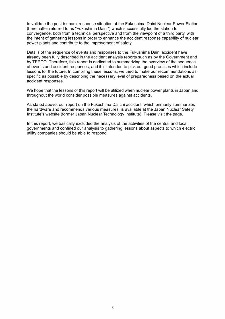
to validate the post-tsunami response situation at the Fukushima Daini Nuclear Power Station (hereinafter referred to as "Fukushima Daini") which successfully led the station to convergence, both from a technical perspective and from the viewpoint of a third party, with the intent of gathering lessons in order to enhance the accident response capability of nuclear power plants and contribute to the improvement of safety.
Details of the sequence of events and responses to the Fukushima Daini accident have already been fully described in the accident analysis reports such as by the Government and by TEPCO. Therefore, this report is dedicated to summarizing the overview of the sequence of events and accident responses, and it is intended to pick out good practices which include lessons for the future. In compiling these lessons, we tried to make our recommendations as specific as possible by describing the necessary level of preparedness based on the actual accident responses.
We hope that the lessons of this report will be utilized when nuclear power plants in Japan and throughout the world consider possible measures against accidents.
As stated above, our report on the Fukushima Daiichi accident, which primarily summarizes the hardware and recommends various measures, is available at the Japan Nuclear Safety Institute’s website (former Japan Nuclear Technology Institute). Please visit the page.
In this report, we basically excluded the analysis of the activities of the central and local governments and confined our analysis to gathering lessons about aspects to which electric utility companies should be able to respond.
3

2. Overview of Fukushima Daini Nuclear Power Station
2.1 Overall Layout
Fukushima Daini is located in the towns of Naraha and Tomioka in Futaba-gun, Fukushima Prefecture, about 12 km south of Fukushima Daiichi, facing the Pacific Ocean to the east. The site is approximately 147 million m2 and its shape is almost square.
At present, four units of boiling water reactors have been installed and are arranged in the order of No. 1, 2, 3, and 4 from the south. The generating capacity of these units is 1,100 MW each, making for a total installed capacity of power generation of 4,400 MW.
When the recent disaster occurred, all units 1 to 4 were in operation at the rated thermal output.
One central control room controls two units of reactors in a twin plant design: Units 1 and 2 make up one pair and Units 3 and 4 another.
Type Location Unit
Start of Operation Reactor Pressure Vessel
Output(MW) Situation when
event happened
1 S57.4 Mark II 1,100 Naraha town 2 S59.2 1,100
3 S60.6 1,100 Tomioka town 4 S62.8
BWR5 Mark II R Advanced
1,100
In operation at the rated thermal
output
Fig 2.1 Overall Layout of Power Stations
Waste Treatment Building
Unit 4
Unit 3
Unit 2
Unit 1
Main Office Building
Important Seismic Isolation Building Reactor Building
Turbine Building
Seawater Heat Exchanger Building
4

2.2 System Configuration
The system configuration of each unit of Fukushima Daini is as shown in Fig 2.2. The role of each system is as follows:
• Reactor Core Isolation Cooling System (RCIC)
In the event that the main condenser is no longer available for any reason, such as closure of the main steam isolation valve during normal operation, steam from the reactor will activate the turbine drive pump to inject the water in the condensate storage tank (referred to as "CST" below) into the reactor, and reduce the pressure by removing the decay heat of the fuel. The system also works as an emergency water injection pump in case of the failure of the water supply system, etc., and maintains the water level in the reactor.
• Residual Heat Removal System (RHR)
After shutting down the reactor, the system will cool the coolant (remove the decay heat of the fuel) using pumps and the heat exchangers, or maintain the level of reactor water by injecting cooling water in case of an emergency (part of ECCS). The system has the ability to bring the reactor to cold shutdown and has five modes of operation: reactor shutdown cooling mode, low-pressure injection mode (ECCS), containment spray mode, pressure suppression chamber cooling mode, and emergency heat load mode.
• Emergency Core Cooling System (ECCS)
The system consists of four subsystems: low pressure core spray system (LPCS), low pressure water injection system, high pressure core spray system (HPCS) and automatic depressurization system. In the case that a loss-of-coolant accident (LOCA) has occurred due to a piping break in the reactor coolant pressure boundary, such as the primary loop recirculation system piping, the system will remove the residual heat and the decay heat of the fuel in the reactor core, preventing the fuel cladding tube from being damaged by the fuel overheating, and consequently, minimize and suppress the water-zirconium reaction to a negligible extent.
• Standby Liquid Control System (SLC)
If and when control rod insertion becomes impossible for any reason during reactor operation, the system will inject a neutron-absorbing boric acid solution from the bottom of the reactor core as a backup for the control rod to stop the nuclear reaction.
5
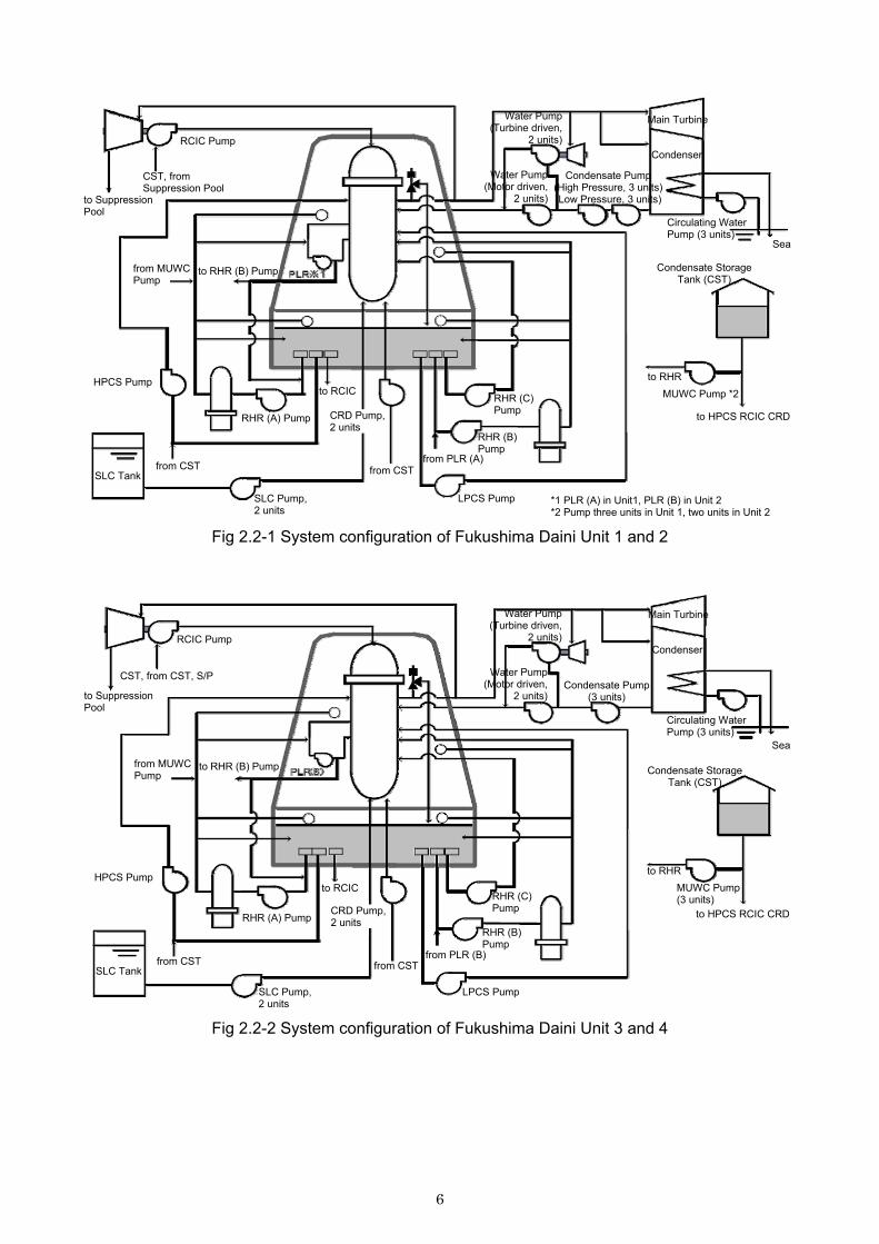
Fig 2.2-1 System configuration of Fukushima Daini Unit 1 and 2
Fig 2.2-2 System configuration of Fukushima Daini Unit 3 and 4
RCIC Pump
Water Pump(Turbine driven,
2 units)
CST, from Suppression Pool
Water Pump(Motor driven,
2 units)to Suppression Pool
Condensate Pump (High Pressure, 3 units) (Low Pressure, 3 units)
Main Turbine
Condenser
Circulating Water Pump (3 units)
Sea
Condensate Storage Tank (CST)
to RHR
MUWC Pump *2
to HPCS RCIC CRD
*1 PLR (A) in Unit1, PLR (B) in Unit 2 *2 Pump three units in Unit 1, two units in Unit 2
from MUWC Pump
to RHR (B) Pump
HPCS Pump
RHR (A) Pump
to RCIC
CRD Pump, 2 units
from CSTfrom CST SLC Tank
SLC Pump, 2 units
LPCS Pump
from PLR (A)
RHR (B) Pump
RHR (C) Pump
to Suppression Pool
RCIC Pump
Water Pump(Turbine driven,
2 units)
Water Pump(Motor driven,
2 units)Condensate Pump
(3 units)
Main Turbine
Condenser
Circulating Water Pump (3 units)
Sea
Condensate Storage Tank (CST)
to RHR
MUWC Pump (3 units)
to HPCS RCIC CRD
from MUWC Pump
to RHR (B) Pump
HPCS Pump
RHR (A) Pump
to RCIC
CRD Pump, 2 units
from CSTfrom CST SLC Tank
SLC Pump, 2 units
LPCS Pump
from PLR (B)
RHR (B) Pump
RHR (C) Pump
CST, from CST, S/P
6

2.3 Power Supply System
The electricity generated by these units is transmitted via two 500 kV lines (Tomioka Line) to the power grid. The transmission capacity of one Tomioka line is sufficient for all the electricity generated at Fukushima Daini, and therefore the power plant can continue full output generation even in the case of failure in one transmission line.
The power plant receives the power for starting and shutting down the reactor via two Tomioka Lines as the main circuits, or via two 66 kV lines (Iwaido Line) as the backup circuit.
In the event of a blackout of these two Tomioka Lines and two Iwaido Lines, the emergency electricity to safely shut down the reactor is powered by emergency diesel generators (D/G) and D/G in the high pressure core spray system (HPCS).
The Iwaido and Tomioka lines are shared by all units.
7

Fig 2.3-1 Power system diagram, skeleton diagram of emergency power system
500 kV Tomioka Line 66 kV Iwaido Line
Series 1 Series 2 Series 1 Series 2
G G G G
Unit 1 Unit 2 Unit 3 Unit 4
High Voltage Startup Transformer
Startup Switching Station
66 kV Electric Boiler Switching
Station
Startup Transformer 1SA
Startup Transformer 1SB
Startup Transformer3SA
Startup Transformer3SB
6.9 kV M/C1SA-1
6.9 kV M/C 1SA-2
6.9 kV M/C 1SB-1
6.9 kV M/C1SB-2
6.9 kV M/C3SA-1
6.9 kV M/C3SA-2
6.9 kV M/C3SB-1
6.9 kV M/C3SB-2
Circuit Breaker ON
Circuit Breaker OFF (Standby)
Charging
HP
CS
Pum
p
*1
D/G(HPCS)
D/G
D/G(A) D/G(B)
Unit 1Note
Note:※1,※3,※5 shall be replaced to read; Replace to read
Unit 1 Unit 2 Unit 3 Unit 4*1 *2 *7 *8 *3 *4 *9 *10 *5 *6 *11 *12
*3D/G *5 D/G
HP
CS
Pum
p
HP
CS
Pum
p
LPC
S P
ump
RH
R P
ump (A
) EE
CW
Pum
p (A)
RH
R P
ump (B
) RH
RC
Pum
p (A
)
RH
RC
Pum
p (C
)
RH
RS
Pum
p (A)
RH
RS
Pum
p (C)
RH
R P
ump (C
) EE
CW
Pum
p (B)
RH
RC
Pum
p (B
)
RH
RC
Pum
p (D
)
RH
RS
Pum
p (B)
RH
RS
Pum
p (D)
8
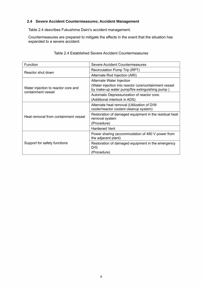
2.4 Severe Accident Countermeasures; Accident Management
Table 2.4 describes Fukushima Daini’s accident management.
Countermeasures are prepared to mitigate the effects in the event that the situation has expanded to a severe accident.
Table 2.4 Established Severe Accident Countermeasures
Function Severe Accident Countermeasures
Recirculation Pump Trip (RPT) Reactor shut down
Alternate Rod Injection (ARI)
Alternate Water Injection (Water injection into reactor core/containment vessel by make-up water pump/fire extinguishing pump ) Water injection to reactor core and
containment vessel Automatic Depressurization of reactor core. (Additional interlock in ADS)
Alternate heat removal (Utilization of D/W cooler/reactor coolant cleanup system)
Restoration of damaged equipment in the residual heat removal system (Procedure)
Heat removal from containment vessel
Hardened Vent
Power sharing (accommodation of 480 V power from the adjacent plant)
Support for safety functions Restoration of damaged equipment in the emergency D/G (Procedure)
9

Fig 2.4-1 Alternate Water Injection
Fig 2.4-2 Hardened Vent
Suppression Pool
D/W
Stack
Reactor Building Exhaust Duct
Standby Gas Treatment System (SGTS)
Rupture Disk
Inert Gas System (Containment
Vessel Boundary)
SGTS System : Boundary of System
Abbreviations RPV : Reactor Pressure Vessel
RCIC : Reactor Core Isolation Cooling
LPCI : Low Pressure Coolant Injection
RHR : Residual Heat Removal
Diesel Driven Pump
Filtered Water Tank
Electric Pump
Electric Pump
Condensate Storage Tank
FP System
MUWC System
Boundary of System RHR System
MUWC System
RHR
MU
WC
System
F
P S
ystem
RCIR
LPCI Water Injection
Pedestal Water Injection
Suppression Pool
D/W
RPV
10

3. Overview of the tsunami caused by the Tohoku-Pacific Ocean Earthquake
3.1 Overview of the Earthquake and the tsunami
The Tohoku-Pacific Ocean Earthquake, which occurred on March 11, 2011, was the biggest earthquake that has ever been observed in Japan in terms of the main shock. In this earthquake, a maximum seismic intensity of 7 was observed in Kurihara City, Miyagi Prefecture.
High tsunamis were observed on the coast of Pacific Ocean in Hokkaido, Tohoku, and the Kanto region.
The focal region of this earthquake ranges from offshore Iwate Prefecture to offshore Ibaraki prefecture, with a size of about 500 km in length and about 200 km in width. The length of maximum slippage was estimated at more than 50 m.
In this earthquake, several large slippages were observed in the offshore of the southern part of Sanriku near the trench, the northern part of Sanriku, and some areas off the coast of the Boso Peninsula near the trench, evidencing that multiple focal regions off the coast of central Sanriku, Miyagi, Fukushima, and Ibaraki concurrently slipped to generate a mega-earthquake of magnitude 9.0 (the fourth largest ever observed in the world). The Headquarters for Earthquake Research Promotion, a national center for the research and study of earthquakes and tsunamis, had been monitoring and evaluating the ground motion of individual regions with case records in the past, but had not assumed for the condition of quakes occurring in all of these areas in conjunction. The Expert Committee of the Central Disaster Management Council has also asserted that this enormous earthquake with a magnitude of 9.0 occurred with several source regions linking together in conjunction, which could not have been assumed from the past few hundred years of our country’s earthquake history.
The tsunami that occurred due to this earthquake and caused the most extreme devastation along the Pacific Ocean coast in the northeastern region of Japan was a magnitude 9.1 on the tsunami scale, making it the fourth largest ever observed in the world and the largest in Japan.
11

Earthquake off Sanriku, March 11, 2011 2:46 pm Seismic Intensity Map
Source: Japan Meteorological Agency (Earthquake off Sanriku, March 11, 2011 2:46 pm Seismic Intensity Map)
Legend
Seismic Intensity 7
Seismic Intensity 6+
Seismic Intensity 6-
Seismic Intensity 5+
Seismic Intensity 5-
Seismic Intensity 4
Seismic Intensity 3
Seismic Intensity 2
Seismic Intensity 1
Epicenter
12

Source: Japan Meteorological Agency (March 2011 Earthquake and Volcanic Activity Monthly Report)
The tsunami is thought to have occurred due to the seabed almost directly above the epicenter rising by about 3 m. The maximum height of tsunami run up above sea level was observed at nearly 35 m in northern Miyako city. The height of the flooding in the northern part of Miyako city was more than 25 m, and there were 58 km2 of flooded areas in Iwate, 327 km2 in Miyagi, 112 km2 in Fukushima, and 23 km2 in Ibaraki.
Seismic Source Time Function
sec.
Starting point of bedrock destruction in the main shock
Epicenter of M7+ shock after March 9
Epicenter of M5+ shock within 1 day after main shock
Center of each small fault
Observation Point used in the analysis
Slippage (m) Contour Interval: 4 m
13

Source: Excerpt from the 1st Meeting Material by The Investigation Committee on the Countermeasures learned as Lessons from the Tohoku-Pacific Ocean Earthquake
As of July 31, 2012, the damage caused by the earthquake and the tsunami is enormous: 15,867 dead, 2,903 missing, 130,445 buildings totally destroyed, and 264,110 buildings partially destroyed.
Aomori Prefecture
Evidence of Tsunami [ Legend ]Offshore Tohoku Flood Height Offshore Tohoku Run-up Height
(Source) • 2011 Tohoku-Pacific
Ocean Earthquake Flood Height and Run-up Height : Preliminary Figures by "Joint Investigation Group on Tohoku-Pacific Ocean Earthquake and Tsunami" (May 9, 2011) Remarks: Based on the Data with Reliability Level A (Highly reliable with clear trace and minimal measurement error) obtained within an area of 200 m from the shoreline.
Iwate Prefecture
Miyagi Prefecture
Fukushima Prefecture
Ibaraki Prefecture
Hachinohe
Miyako
Rikuzentakata
Sendai
Flood Height and Run-up Height
Run-up Height
Flood Height Embankment
Sea level at the time of tsunami arrival
Tokyo Peil: Mean sea level at Tokyo Bay (T.P.)
Flood Height: Height from the sea level at the time of arrival of the tsunami to the traces of tsunami inundation
Run-up Height: Height from the sea level at the time of arrival of the tsunami to the traces of tsunami run-up.
14

3.2 Results of observation at Fukushima Daini
The observed values of ground motion at the foundation of the reactor building (the lowest basement floor) of Fukushima Daini was below the maximum acceleration of design earthquake ground motion Ss (the maximum acceleration observed was 305 Gal on the B2 floor of the Unit 1 reactor building), and therefore this ground motion can be considered to be within the expected range of the seismic safety evaluation of the equipment.
Furthermore, using the recorded values of ground motion at the free field obtained during the earthquake, a soil structure model was identified for the strip analysis. As a result, ground motion of the strip analysis proved to be generally at the same level as actual observations, although the calculated values exceeded the design earthquake ground motion Ss in some of the periodic bands.
Exemplification of larger horizontal direction in table
Fig. 3.2-1-1 Time History of Acceleration on the Ground Level of Reactor Building, Unit 1 (NS Direction)
Fig. 3.2-1-2 Time History of Acceleration on the Ground Level of Reactor Building, Unit 2 (NS Direction)
Fig. 3.2-1-3 Time History of Acceleration on the Ground Level of Reactor Building, Unit 3 (NS Direction)
Fig. 3.2-1-4 Time History of Acceleration on the Ground Level of Reactor Building, Unit 4 (NS Direction)
Fig. 3.2-2-1 Response Spectrum on the Ground Level of Reactor Building, Unit 1 (NS Direction)
Fig. 3.2-2-2 Response Spectrum on the Ground Level of Reactor Building, Unit 2 (NS Direction)
Fig. 3.2-2-3 Response Spectrum on the Ground Level of Reactor Building, Unit 3 (NS Direction)
Fig. 3.2-2-4 Response Spectrum on the Ground Level of Reactor Building, Unit 4 (NS Direction)
Time (sec.)
Time (sec.)
Time (sec.)
Time (sec.)
Acc
ele
ratio
n (
Ga
l) A
cce
lera
tion
(G
al)
Acc
ele
ratio
n (
Ga
l) A
cce
lera
tion
(G
al)
Cycle (sec.)
Cycle (sec.)
Cycle (sec.)
Cycle (sec.)
Acc
ele
ratio
n (
Ga
l) A
cce
lera
tion
(G
al)
Acc
ele
ratio
n (
Ga
l) A
cce
lera
tion
(G
al)
Recorded Measurement Basic Seismic Movement Ss-1 Basic Seismic Movement Ss-2 Basic Seismic Movement Ss-3
Recorded Measurement Basic Seismic Movement Ss-1 Basic Seismic Movement Ss-2 Basic Seismic Movement Ss-3
Recorded Measurement Basic Seismic Movement Ss-1 Basic Seismic Movement Ss-2 Basic Seismic Movement Ss-3
Recorded Measurement Basic Seismic Movement Ss-1 Basic Seismic Movement Ss-2 Basic Seismic Movement Ss-3
15

3.3 Data on the earthquake and subsequent tsunami
(1) Date and time of occurrence March 11, 2011, 2:46 pm
(2) Epicenter Off the coast of Sanriku (38.1 N/142.9 E, 130 km ESE of Oshika Peninsula, focal depth 24 km)
(3) Magnitude 9.0
(4) Peak ground acceleration 305 Gal at B2 floor of the Unit 1 reactor building (Vertical)
(5) Distance from Fukushima Daini 183km to epicenter, 185 km to hypocenter
(6) Data on tsunami a Inundation height (a) Seaside area (Ground height at base level of Onahama Port Construction site
(hereinafter O.P.) + 4 m) • About +7 m*1 (flood depth about 3 m) *1) South side of Unit 1 seawater heat exchanger building. Highest point
(b) Main building*2 area (Ground height O.P. + 12 m)*2 Reactor building and Turbine building
• O.P. about +12~+14.5 m*2 (flood depth less than 2.5 m) *2) Between the area south of Unit 1 Main building and the important seismic isolation
building. Locally O.P. about+15~+16 m (flood depth about 3-4 m)
b Flooded area The flooded area extended across the entire seaside area, but no entry of tsunami
seawater into the main building area beyond the slope from the seaside area was observed. The tsunami run up was mostly from the southeast side of the main building area toward the road leading to the important seismic isolation building. As a result, flooding was limited only to the area surrounding the Unit 1 and 2 buildings and the south side of the Unit 3 building (no flooding around the Unit 4 building).
(7) Arrival of the first wave of the tsunami
March 11, 2011 3:22 pm Visual sighting)
16

3.4 Damage of Equipment
3.4.1 Damage by the earthquake
The external power supply of Fukushima Daini consists of a total of four lines: 500 kV of Tomioka 1L and 2L and 66kV of Iwaido 1L and 2L, all from the Shin Fukushima substation. On the day of the earthquake, however, Iwaido 1L was out of service for inspection and only three lines were available.
After the earthquake, Tomioka 2L went out of service at around 2:48 pm on March 11 due to damage to the breakers at the Shin Fukushima substation. After the earthquake, patrol inspection of facilities found damage at the arrester of Iwaido 2L, so after confirming that Tomioka 1L was continuously receiving all the power necessary for the station, Iwaido 2L was put out of service for restoration works in order to prevent the damage from spreading further.
As a result, after the earthquake, the external power supply was only available from a single line for the time being. However, Iwaido 2L resumed service at 1:38 pm on the next day, March 12, and Iwaido 1L was also revived at 5:15 am on March 13 after temporary restoration, giving the receiving configuration three lines.
Maintaining the external power through this single transmission line made it possible to supply power to the available facilities, contributing a great deal to preventing the spread of the accident, and led to early convergence. All the equipment such as circuit breakers, etc. at the substation and switching stations has basically the same specifications as at Fukushima Daiichi.
17

Fig 3.4.1-1 Fukushima Daini Outline Diagram of External Power Supply
Ordinary High Voltage Power Panel(M/C)
Ordinary High Voltage Power Panel (M/C)
Emergency High Voltage Power
Panel (M/C)
Emergency High Voltage Power
Panel (M/C)
Emergency High Voltage Power
Panel (M/C)
Emergency High Voltage Power
Panel (M/C)
Out of service for check and maintenance Trip (Suspended) Circuit Breaker
Dis-connector
Transformer Main Power Generator
Switching Station for
Transformer Start-up Unit 1
Tom
ioka Line 1L
Tom
ioka Line 2L
Iwaido Line Line
1L
Iwaido Line Line
2L
66 kV Startup Switching Station
Switching Station for Auxiliary Boiler
Unit 2 Unit 3 Unit 4
Fukushima Daini Nuclear Power Station
Shin Fukushima Transformer Substation
Suspension of Electric Cable (Out of Service)
Tomioka Line 2L, Suspended
(Suspended after the earthquake but
before the tsunami)
Iwaido Line Series 1, Suspended for repair works
Under construction
18

3.4.2 Damage by the tsunami
(1) Entry of flood water into Main building (Ref: Fig 3.4.2-1, 3.4.2-2)
Inundation surrounding the main buildings of Fukushima Daini (reactor building and turbine building; Ground Level OP +12 m) was not significantly deep, with the exception of intensive run up on the south side of Unit 1.
Intensive tsunami run up entered the Unit 1 building through the openings at ground level located on the south side of the reactor building (air intake louver for the emergency D/G, equipment hatch on the ground level) which flooded the reactor building (annex building) and caused the loss of function of all three units of emergency D/G, emergency power supply (for the C system and high pressure core spray system).
The depth of run up around Unit 2 through Unit 4 was not significant, and thus flooding into the reactor buildings or turbine buildings through the openings at ground level was not detected. However, flooding was confirmed in the basement of the reactor building of Unit 3 (Annex) and the basements of turbine buildings Unit 1 through Unit 3. It is thought that tsunami inundation entered the buildings through the cables and pipes leading to the underground trenches and ducts.
Fig 3.4.2-1 Openings of flood entrance into the main building
Fig 3.4.2-2 Flow path of flood to the main buildings of Fukushima Daini
Openings on the ground where the flood enteredthe main building Openings leading to the underground trench duct where the flood entered the main building
Unit 1Unit 2Unit 3Unit 4
Seawater Heat Exchanger Building
Turbine Building
Reactor Building
Unit 2-4, No significant water entry through the louver/hatch to the reactor building annex
Unit 1, Water entry through louver/hatch to the reactor building annex
Ground Level O.P. + 12 m
Ground Level O.P. + 4m
Flood Height: O.P. + about 7 m
Equipment Hatch
Seawater Heat Exchanger Building
Building Entrance
Seawall Drainage Pump
Power Panel
Reactor Building Annex
Main Reactor Building
D/G Air Intake Louver
Equipment Hatch
Power Panel
Reactor Building Annex
Reactor Building Annex
Main Reactor Building
Reactor Building Annex
19

Table 3.4.2-1 Location of D/G and damages thereto
Unit 1 Unit 2 Unit 3 Unit 4
Height of tsunami*1 About +9 m
Ground Level O.P.+12 m
Flood depth around main buildings
[Inundation Height]
Less than 2.5 m (nearly zero except around Unit 1) [O.P .about+12 m~+14.5 m] *2
A Reactor Bldg.
Annex [B2F]
Reactor Bldg. Annex [B2F]
Reactor Bldg. Annex [B2F]
Reactor Bldg. Annex [B2F]
B Reactor Bldg.
Annex [B2F]
Reactor Bldg. Annex [B2F]
Reactor Bldg. Annex [B2F]
Reactor Bldg. Annex [B2F]
Building where D/G is installed [Floor]
H Reactor Bldg.
Annex [B2F]
Reactor Bldg. Annex [B2F]
Reactor Bldg. Annex [B2F]
Reactor Bldg. Annex [B2F]
□:D/G unit flooded □:D/G unit not flooded
*1 *2
Estimate at tide station. Actual measurement unknown because of instrument damage. Locally about OP+15 – 16 m [flood depth about 3 – 4 m] in the area between the south side of the Unit 1 main building and the important quake proof building.
(2) Damage situation
Among the equipment for reactor cooling that was also damaged by the tsunami, the damage situation of the facilities that clearly show characteristics of equipment damage caused by the recent tsunami is explained as below.(Please refer to Table 3.4.2-2.)
① Emergency equipment cooling pump Units 1 through 4 use seawater to remove decay heat from the reactor. The emergency D/G unit also uses seawater to cool its engine. Therefore, the pumps for the emergency equipment cooling water system (the seawater intake pump and the fresh water cooling pump sourced from seawater) are installed in the seaside area. These pumps are installed in the seawater heat exchanger building. The purpose of the overall layout in which seawater is not sent directly to the reactor building but to the intermediate seawater heat exchanger building, which is not a radiation control area, where a freshwater loop is installed with a heat exchanger and cooling pump for auxiliary equipment constituting an independent set of equipment cooling facilities, is to prevent seawater from mixing with reactor water and to improve maintenance works. The pumps for the emergency equipment cooling water system are specified for outdoor use, but they were installed indoors in the heat exchanger building as part of the independent set of equipment cooling facilities. The ground level of the seaside area where the pumps for the emergency equipment cooling water system are installed had OP +4 m elevation, and its precautionary measures ensured safety against a tsunami height of 5.1 - 5.2 m, based on the tsunami height evaluation results in 2002 provided by the Japan Society of Civil Engineers “Tsunami Evaluation Technology”. However, this tsunami greatly exceeded expectations, and the motors of the pumps were submerged under the water and the system lost function. The pumps for the emergency equipment cooling water system at Fukushima Daini were housed in the seawater heat exchanger buildings. The area surrounding the buildings was inundated to a depth of 3 m by the tsunami, and while there was no damage to the building structures, all the seawater heat exchanger buildings were flooded by seawater through the damaged doors and other openings on ground level. As a result, the
20

power panels and the motor of the pumps were submerged underwater and the total of eight emergency equipment cooling water systems lost function except for one system of Unit 3. In addition, the cooling system of the three D/G units, A, B and H installed for each reactor Unit also lost all function except for three systems: B and H of Unit 3 and H of Unit 4.
② Power panel The scale of the tsunami at Fukushima Daini was different from that at Fukushima Daiichi, and inundation of the main building was also different. Accordingly, the situations of power panel damage also differ as a result.
The Reactor building of Unit 1 (Annex), which was flooded by the tsunami, saw inundation on the emergency power panels of the C and H systems, but the D system power panel was not flooded and all the power panels of other reactor Units were free of damage. Due to this situation, it was possible to distribute electric power received from outside sources to various pieces of equipment through these emergency circuits, making it possible to use the necessary facilities to cope with the emergency situation (distribution through Normal A and B2, Emergency C and D2, and high pressure core spray system H). On the other hand, the power panels in the seawater heat exchanger buildings located in the seaside area were all submerged in the tsunami because of flooding in the buildings, and seven power panels lost function, with the exception of one low voltage power panel (P/C) situated in the seawater heat exchanger building of Unit 3.
Therefore, the residual heat removal seawater system lost function except for one system of Unit 3 out of the total of eight.
Table 3.4.2-2 Damage situation of the cooling pumps for emergency equipment and emergency P/C located in the seawater heat exchanger buildings after the tsunami
Seawater Pump (RHRC, RHRS and LLCW) ○ Usable △ Out of service due to flooding of Power Panel× Out of service due to flooding of Power Panel and Motor
Unit 1 Unit 2 Unit 3 Unit 4
Emergency P/C
Unit 1 Unit 2 Unit 3 Unit 4
○ Usable× Out of service due to flooding
North side South side North side South side North side South side North side South side
North side South side North side South side North side South side North side South side
2n
d
Floor
Gro
un
d Flo
or
Loca
tion
o
f Installati
on
Loca
tion
o
f Installati
on
Gro
un
d
Floor
21

③ Emergency Diesel Generator In the Fukushima Daini power station, each reactor Unit has three (A, B, H) emergency diesel generators (hereinafter referred to as "emergency D/G"). Unit 1 lost all three emergency D/Gs because the tsunami had entered the reactor building (Annex) through the opening at the ground level. Some of the emergency D/Gs which were able to avoid the flooding still lost function because of the loss of diesel engine cooling due to the flooding of the power panel and the pump motor for the cooling system. The cooling system of the emergency D/G was lost for most of the systems except for three: B and H of Unit 3 and H of Unit 4. As a result, nine D/Gs lost function: A, B and H of Unit 1, A, B and H of Unit 2, A of Unit 3 as well as A and B of Unit 4.
However, Fukushima Daini had a continuous supply of electric power from the external sources and there was no need to activate such surviving emergency D/G after all.
④ Situation of other outdoor damage In the Fukushima Daini power station area, no major equipment and/or structure was observed being washed up by the tsunami to the main building area (elevation OP +12 m).
However, five cases of openings/holes caused by the tsunami washing away or damaging the lid of the hatch duct in the main building area have been reported.
Source;
Tokyo Electric Power Company The impact of Tohoku-Chihou Taiheiyo-Oki Earthquake to Nuclear Reactor Facilities at Fukushima Daini Nuclear Power Station (May 9, 2012) Fukushima Nuclear Accident Analysis Report (June 20, 2012)
Investigation Committee on the Accident at the Fukushima Nuclear Power Stations of Tokyo Electric Power Company
Final Report (July 23, 2012)
22

4. Response to the accident at Fukushima Daini
The status of the accident at Fukushima Daini has already been reported in detail in the reports of TEPCO and the Investigation Committee of the Government. Therefore, this report puts the emphasis on describing the situation, including points of suggestion in considering the lessons learned, and giving a brief overview of the other points.
Fig 4-1 shows the operational status of the responses of Units 1 through 4, and Figs 4-2 to 4-5 show the operational status of each Unit in conjunction with the changes in the main parameters of each Unit.
23

8:00 12:00 0:0016:00 20:000:00 4:00 8:00 12:00 16:00 20:00 0:00 4:00March 14 March 15 March 16
12:00 0:00 4:00 8:00 12:00 16:00 20:0016:00 20:00March 12 March 13
20:00 0:00 4:00 8:004:00 16:00
Unit 4
Unit 1
Unit 2
12:00 8:00 12:00March 11
Unit 3
16:00 20:00 0:00
Report pursuant to Article 10 of the Act on Special Measures Concerning Special Law for Nuclear Emergency (loss of reactor heat removal function) (18:33 on March 11 – 1:24 on March 14)
▲17:53 D/W cooling system manual start
▲0:00 MUWC alternative water injection start
▲D/W spray (7:10 – as appropriate)S/C cooling by FCS cooling water (MUWC)(6:20~7:20)
▲S/C spray (7:37 – as appropriate) ▽9:40 MUWC alternative water injection Stopped
Configuration of pressure proof vent-line (10:21 – 18:30)
▲20:17 RHRS(B) Manual start▲21:03 RHRC(D) Manual start
▲1:24 RHR(B) Start Call-off pursuant to Article 10 of the Act on Special Measures Concerning Special Law for Nuclear Emergency
▲1:44 Emergency component cooling system (B) manual start
▲3:39 S/C spray by RHR (B) start▲10:05 Reactor water injection by means of RHR (B) LPCI mode
▲16:30 SFP water injection by FPMUW start
▲17:00 Reactor cold shutdown
▲20:26 FPC (B) circulation operation start
▲0:42RHR(B) SFP cooling start
▲▽15:34 Emergency D/G A, B and H automatic start followed by immediate trip▽15:33 CWP(C) Manual stop
Water injection by RCIC (15:36 – 4:58)
▲15:36 MSIV manual full-close
▽15:57 CWP(A,B) Automatic stop▲Rapid depressurization (3:50 – 4:56)]
▲▽15:34 Emergency D/G H automatic start followed by immediate trip
Water injection by RCIC (15:41 – 4:53)
▲15:34 MSIV manual full-close▲15:35 RHR(B) Manual start
▽15:38 RHR(B) Stop▽15:35 CWP(C) Manual stop, (A and B) automatic stop
▲▽15:41 Emergency D/G A and B automatic start followed by immediate trip
Report pursuant to Article 10 of the Act on Special Measures Concerning special Law Nuclear Emergency Preparedness (loss of reactor heat removal function) (18:33 on March 11 – 7:13 on March 14)
Report pursuant to Article 15 of the Act on Special Measures Concerning Special Law for Nuclear Emergency (loss of pressure suppression function) (5:32 on March 12 – 15:52 on March 14)
▲20:02 D/W cooling systemmanual start
▲4:50 MUWC alternative water injection start▲D/W spray (7:11 – as appropriate)
S/C cooling by FCS cooling water (MUWP) (6:20 – 7:52)
▲S/C spray (7:35 – as appropriate)
Configuration of pressure proof vent-line (10:33 – 10:58)
▲15:50~asappropriateReactordepressurization
▽10:12 MUWC alternative water injection stopped
▲3:20 Emergency component cooling system (B) manual start
▲3:51 RHRS(B) Manual start▲5:52 RHRC(B) Manual start
▲7:13 RHR(B) Start (S/C cooling mode) Call-off pursuant to Article 10 of the Act on Special Measures Concerning Nuclear Emergency▲7:50 RHR(B)S/C Spray start
▲10:48 Reactor water injection by means of RHR (B) LPCI mode
▲18:00 Reactor cold shutdown ▲1:28 RHR(B) SFP cooling start
▽15:34 CWP(C) Manual stop▲▽15:35 Emergency D/G A, B and H automatic start followed by immediate trip of A
▲15:36 RHR(B) S/C cooling start
▲15:37 MSIV manual full-close▽15:38 CWP(B) Manual stop
Water injection by RCIC (16:06 – 23:58)
▽16:48 CWP(A) Manual stop
▲19:46 RHR(B) S/C cooling Switch to LPCI mode▲20:07 RHR(B) LPCI mode Switch to S/C cooling
▲20:12 D/W cooling system manual start
▲22:53 MUWC alternative water injection start (unknown when stopped)
Configuration of pressure proof vent-line (12:08 – 12:13)
▲0:06 RHR(B) Commencement of configuration of SHC mode system▽1:23 RHR(B) Manual stop, prepare for SHC mode being on
▲2:39 RHR(B) Manual start (S/C cooling start)▲2:41 RHR(B)S/C Spray start
▽7:59 RHR(B) Manual stop
▲9:37 RHR(B) Manual start (commencement of SHC)
▲12:15 Reactor cold shutdown▲17:42 FPC Hx cooling water switch-over (RCW RHRC)
▲10:30 SFP water temperatureapproximately 38°C (beforeearthquake)
▲10:30 SFP water temperatureapproximately 32.5°C (beforeearthquake)
▲22:30 SFP water temperature approximately
32.5°C (before earthquake)
▽15:33 CWP(C) Manual stop▲▽15:34 Emergency D/G A, B and H automatic start followed by immediate trip of A and B▽15:34 CWP(A,B) Automatic stop▲15:36 MSIV manual full-close▲15:36 RHR(A,B) Manual start▽15:38 RHR(A) Manual stop▽15:41 RHR(B) Automatic stop
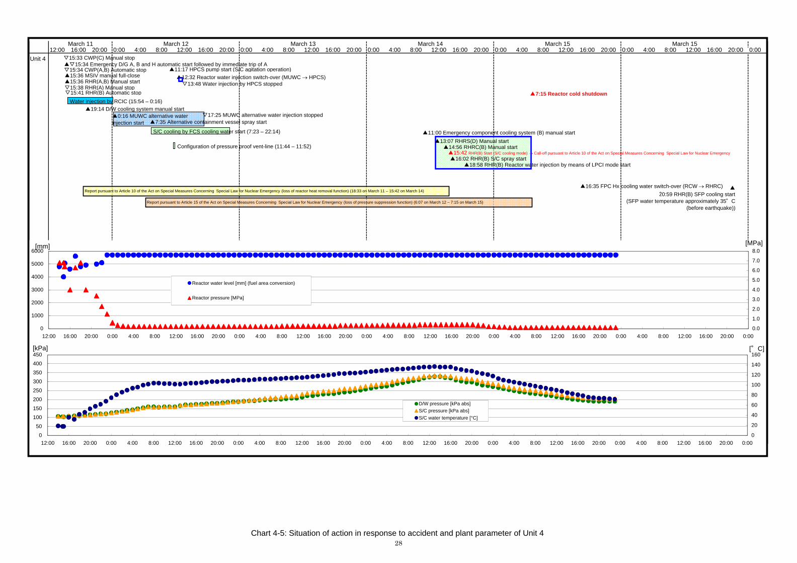
Water injection by RCIC (15:54 – 0:16)
Report pursuant to Article 10 of the Act on Special Measures Concerning Special Law for Nuclear Emergency (loss of reactor heat removal function) (18:33 on March 11 – 15:42 on March 14)
▲19:14 D/W cooling system manual start▲0:16 MUWC alternative waterinjection start ▲7:35 Alternative containment vessel spray start
▽17:25 MUWC alternative water injection stopped
Report pursuant to Article 15 of the Act on Special Measures Concerning Special Law for Nuclear Emergencys (loss of pressure suppression function) (6:07 on March 12 – 7:15 on March 15)
S/C cooling by FCS cooling water (MUWP)(7:23 – 22:14)
▲11:17 HPCS pump start (S/C agitation operation)
Configuration of pressure proof vent-line (11:44 – 11:52)
▲12:32 Reactor water injection switch-over (MUWC HPCS)▽13:48 Water injection by HPCS stop
▲11:00 Emergency component cooling system (B) manual start
▲13:07 RHRS(D) Manual start▲14:56 RHRC(B) Manual start▲15:42 Start (S/C cooling mode) Call-off pursuant to Article 10 of the Act on Special Measures Concerning Special Law for Nuclear Emergency▲16:02 RHR(B)S/C Spray start
▲18:58 Reactor water injection by means of RHR (B) LPCI mode start
▲7:15 Reactor cold shutdown
▲16:35 FPC Hx cooling water switch-over (RCW → RHRC)
▲20:59 RHR(B) SFP cooling start
(7:30 on March 18: SFP water temperature approximately 35°C(before earthquake))
▲Around 22:00 Commence site observation (around Hx / B) ▲Around 6:00 Equipment and materials arrived▲Around 23:30 Completion of temporary cable-laying
▲Before dawn: Cable-laying, Unit 1 being of priority (Unit 2 Unit 1)
Report pursuant to Article 15 of the Act on Special Measures Concerning Special Law for Nuclear Emergency (loss of pressure suppression function) (5:22 on March 12 – 10:15 on March 14)
Chart 4-1: Situation of action in response to the Unit 1 – Unit 4 accident24

Unit 1
8:00 12:00 0:0016:00 20:000:00 4:00 8:00 12:00 16:00 20:00 0:00 4:00March 14 March 15 March 16
12:00 0:00 4:00 8:00 12:00 16:00 20:00March 11
16:00 20:00March 12 March 13
20:00 0:00 4:00 8:004:00 8:00 12:00 16:0012:00 16:00 20:00 0:00
Report pursuant to Article 10 of the Act on Special Measures Concerning Special Law for Nuclear Emergency (loss of reactor heat removal function) (18:33 on March 11 – 1:24 on March 14)
▲0:00 MUWC alternative water injection start
▲D/W spray (7:10 – as appropriate)S/C cooling by FCS cooling water (MUWC) (6:20 – 7:20)
▲S/C spray (7:37 – as appropriate)▽9:40 MUWC alternative water injection stopped
Configuration of pressure proof vent-line (10:21 – 18:30)▲20:17 RHRS(B) Manual start▲21:03 RHRC(D) Manual start
▲1:24 RHR(B) Start Call-off pursuant to Article 10 of the Act on Special Measures Concerning Special Law for Nuclear Emergency
▲1:44 Emergency component cooling system (B) manual start
▲3:39 S/C spray by RHR (B) start▲10:05 Reactor water injection by means of LPCI mode
▲16:30 SFP water injection by FPMUW start
▲17:00 Reactor cold shutdown
▲20:26 FPC(B) Circulation operation start▲0:42 RHR(B) SFP cooling start
▲▽15:34 Emergency D/G A, B and H automatic start followed by immediate trip▽15:33 CWP(C) Manual stop
Water injection by RCIC (15:36 – 4:58)
▲15:36 MSIV manual full-close
▽15:57 CWP(A,B) Automatic stop▲Rapid depressurization (3:50 – 4:56)▲15:50 – as appropriate
Reactordepressurization
▲10:30 SFP water temperatureapproximately 38°C (beforeearthquake)
0
1000
2000
3000
4000
5000
6000
12:00 16:00 20:00 0:00 4:00 8:00 12:00 16:00 20:00 0:00 4:00 8:00 12:00 16:00 20:00 0:00 4:00 8:00 12:00 16:00 20:00 0:00 4:00 8:00 12:00 16:00 20:00 0:00 4:00 8:00 12:00 16:00 20:00 0:00
0.0
1.0
2.0
3.0
4.0
5.0
6.0
7.0
8.0
Reactor water level [mm] (fuel area conversion)
Reactor pressure [MPa]
0
50
100
150
200
250
300
350
400
450
12:00 16:00 20:00 0:00 4:00 8:00 12:00 16:00 20:00 0:00 4:00 8:00 12:00 16:00 20:00 0:00 4:00 8:00 12:00 16:00 20:00 0:00 4:00 8:00 12:00 16:00 20:00 0:00 4:00 8:00 12:00 16:00 20:00 0:00
0
20
40
60
80
100
120
140
160
D/W pressure [kPa abs]
S/C pressure [kPa abs]
S/C water temperature [°C]
[mm] [MPa]
[kPa]
Measurement missingdue to paper jam
[°C]
▲17:53 D/W cooling systemmanual start
Report pursuant to Article 15 of the Act on Special Measures Concerning Special Law for Nuclear Emergency (loss of pressure suppression function) (5:22 on March 12 – 10:15 on March 14)
Chart 4-2: Situation of action in response to accident and plant parameter of Unit 125

Unit 2
8:00 12:00 0:0016:00 20:000:00 4:00 8:00 12:00 16:00 20:00 0:00 4:00March 14 March 15 March 16
12:00 0:00 4:00 8:00 12:00 16:00 20:00March 11
16:00 20:00March 12 March 13
20:00 0:00 4:00 8:004:00 8:00 12:00 16:0012:00 16:00 20:00 0:00
0
1000
2000
3000
4000
5000
6000
12:00 16:00 20:00 0:00 4:00 8:00 12:00 16:00 20:00 0:00 4:00 8:00 12:00 16:00 20:00 0:00 4:00 8:00 12:00 16:00 20:00 0:00 4:00 8:00 12:00 16:00 20:00 0:00 4:00 8:00 12:00 16:00 20:00 0:00
0.0
1.0
2.0
3.0
4.0
5.0
6.0
7.0
8.0
Reactor water level [mm] (fuel area conversion)
Reactor pressure [MPa]
[mm] [MPa]
▲▽15:34 Emergency D/G H automatic start followed by immediate trip
Water injection by RCIC (15:41 – 4:53)
▲15:34 MSIV manual full-close▲15:35 RHR(B) Manual start
▽15:38 RHR(B) Stop▽15:35 CWP(C) Manual stop, (A and B) Automatic stop
▲▽15:41 Emergency D/G A,B Automatic start followed by immediate trip
Report pursuant to Article 10 of the Act on Special Measures Concerning Special Law for Nuclear Emergencys (loss of reactor heat removal function) (18:33 on March 11 – 7:13 on March 14)
Report pursuant to Article 15 of the Act on Special Measures Concerning Special Law for Nuclear Emergency (loss of pressure suppression function) (5:32 on March 12 – 15:52 on March 14)
▲20:02 D/W cooling system manual start
▲4:50 MUWC alternative water injection start▲D/W spray (7:11 – as appropriate)
S/C cooling by FCS cooling water (MUWP) (6:20 – 7:52)
▲S/C spray (7:35 – as appropriate)
Configuration of pressure proof vent-line (10:21 – 18:30)
▽10:12 MUWC alternative water injection stopped
▲3:20 Emergency component cooling system (B) manual start
▲3:51 RHRS(B) Manual start▲5:52 RHRC(B) Manual start
▲7:13 Start (S/C cooling mode) Call-off pursuant to Article 10 of the Act on Special Measures Concerning Special Law for Nuclear Emergency▲7:50 RHR(B) S/C spray start
▲10:48 RHR(B) Reactor water injection by means of LPCI mode
▲18:00 Reactor cold shutdown
▲1:28 RHR(B) SFP cooling start
▲15:41 – as appropriate Reactor depressurization as
●:D/W圧力 [kPa abs]●:S/C圧力 [kPa abs]
0
50
100
150
200
250
300
350
400
450
12:00 16:00 20:00 0:00 4:00 8:00 12:00 16:00 20:00 0:00 4:00 8:00 12:00 16:00 20:00 0:00 4:00 8:00 12:00 16:00 20:00 0:00 4:00 8:00 12:00 16:00 20:00 0:00 4:00 8:00 12:00 16:00 20:00 0:00
0
20
40
60
80
100
120
140
160
D/W pressure [kPa abs]
S/C pressure [kPa abs]
S/C water temperature [°C]
[°C][kPa]
▲10:30 SFP water temperatureapproximately 32.5°C (beforeearthquake)
Chart 4-3: Situation of action in response to accident and plant parameter of Unit 226

Unit 3
8:00 12:00 0:0016:00 20:000:00 4:00 8:00 12:00 16:00 20:00 0:00 4:00March 14 March 15 March 16
12:00 0:00 4:00 8:00 12:00 16:00 20:00March 11
16:00 20:00March 12 March 13
20:00 0:00 4:00 8:004:00 8:00 12:00 16:0012:00 16:00 20:00 0:00
0
1000
2000
3000
4000
5000
6000
12:00 16:00 20:00 0:00 4:00 8:00 12:00 16:00 20:00 0:00 4:00 8:00 12:00 16:00 20:00 0:00 4:00 8:00 12:00 16:00 20:00 0:00 4:00 8:00 12:00 16:00 20:00 0:00 4:00 8:00 12:00 16:00 20:00 0:00
0.0
1.0
2.0
3.0
4.0
5.0
6.0
7.0
8.0
Reactor water level [mm] (fuel area conversion)
Reactor pressure [MPa]
▽15:34 CWP(C) Manual stop▲▽15:35 Emergency D/G A, B and H automatic start followed by immediate trip of A
▲15:36 RHR(B) S/C cooling start
▲15:37 MSIV manual full-close▽15:38 CWP(B) Manual stop
Water injection by RCIC (16:06 – 23:58)
▽16:48 CWP(A) Manual stop
▲19:46 RHR(B) S/C cooling switch-over to LPCI mode▲20:07 RHR(B) LPCI mode switch-over to S/C cooling
▲20:12 D/W cooling system manual start
▲22:53 MUWC alternative water injection start (unknown when stopped)
Configuration of pressure proof vent-line (12:08 – 12:13)
▲0:06 RHR(B) Configuration of SHC mode system start▽1:23 RHR(B) Manual stop (prepare for SHC mode being on)
▲2:39 RHR(B) Manual start (S/C cooling start)▲2:41 RHR(B) S/C spray start
▽7:59 RHR(B) Manual stop
▲9:37 RHR(B) Manual start (SHC start)
▲12:15 Reactor cold shutdown
▲17:42 FPC Hx cooling water switch-over (RCW RHRC)
▲22:30 SFP water temperature approximately
32.5°C (before earthquake)
▽15:33 CWP(C) Manual stop▲▽15:34 Emergency D/G A, B and H automatic start followed by immediate trip of A and B
▲11:00 Emergency component cooling system (B) manual start
Measurement missingdue to paper jam
0
50
100
150
200
250
300
350
400
450
12:00 16:00 20:00 0:00 4:00 8:00 12:00 16:00 20:00 0:00 4:00 8:00 12:00 16:00 20:00 0:00 4:00 8:00 12:00 16:00 20:00 0:00 4:00 8:00 12:00 16:00 20:00 0:00 4:00 8:00 12:00 16:00 20:00 0:00
0
20
40
60
80
100
120
140
160D/W pressure [kPa abs]
S/C pressure [kPa abs]
S/C water temperature [°C]
[mm]
[kPa]
[MPa]
[°C]
Chart 4-4: Situation of action in response to accident and plant parameter of Unit 327
Unit 4
8:00 12:00 0:0016:00 20:000:00 4:00 8:00 12:00 16:00 20:00 0:00 4:00March 14 March 15 March 15
12:00 0:00 4:00 8:00 12:00 16:00 20:00March 11
16:00 20:00March 12 March 13
20:00 0:00 4:00 8:004:00 8:00 12:00 16:0012:00 16:00 20:00 0:00
0
1000
2000
3000
4000
5000
6000
12:00 16:00 20:00 0:00 4:00 8:00 12:00 16:00 20:00 0:00 4:00 8:00 12:00 16:00 20:00 0:00 4:00 8:00 12:00 16:00 20:00 0:00 4:00 8:00 12:00 16:00 20:00 0:00 4:00 8:00 12:00 16:00 20:00 0:00
0.0
1.0
2.0
3.0
4.0
5.0
6.0
7.0
8.0
Reactor water level [mm] (fuel area conversion)
Reactor pressure [MPa]
0
50
100
150
200
250
300
350
400
450
12:00 16:00 20:00 0:00 4:00 8:00 12:00 16:00 20:00 0:00 4:00 8:00 12:00 16:00 20:00 0:00 4:00 8:00 12:00 16:00 20:00 0:00 4:00 8:00 12:00 16:00 20:00 0:00 4:00 8:00 12:00 16:00 20:00 0:00
0
20
40
60
80
100
120
140
160
D/W pressure [kPa abs]
S/C pressure [kPa abs]
S/C water temperature [°C]
[mm] [MPa]
[kPa]
▽15:33 CWP(C) Manual stop▲▽15:34 Emergency D/G A, B and H automatic start followed by immediate trip of A
d B▽15:34 CWP(A,B) Automatic stop▲15:36 MSIV manual full-close▲15:36 RHR(A,B) Manual start▽15:38 RHR(A) Manual stop▽15:41 RHR(B) Automatic stop
Water injection by RCIC (15:54 – 0:16)
Report pursuant to Article 10 of the Act on Special Measures Concerning Special Law for Nuclear Emergency (loss of reactor heat removal function) (18:33 on March 11 – 15:42 on March 14)
▲19:14 D/W cooling system manual start▲0:16 MUWC alternative waterinjection start ▲7:35 Alternative containment vessel spray start
▽17:25 MUWC alternative water injection stopped
Report pursuant to Article 15 of the Act on Special Measures Concerning Special Law for Nuclear Emergency (loss of pressure suppression function) (6:07 on March 12 – 7:15 on March 15)
S/C cooling by FCS cooling water start (7:23 – 22:14)
▲11:17 HPCS pump start (S/C agitation operation)
Configuration of pressure proof vent-line (11:44 – 11:52)
▲12:32 Reactor water injection switch-over (MUWC HPCS)▽13:48 Water injection by HPCS stopped
▲11:00 Emergency component cooling system (B) manual start
▲13:07 RHRS(D) Manual start▲14:56 RHRC(B) Manual start▲15:42 RHR(B) Start (S/C cooling mode) Call-off pursuant to Article 10 of the Act on Special Measures Concerning Special Law for Nuclear Emergency
▲16:02 RHR(B) S/C spray start▲18:58 RHR(B) Reactor water injection by means of LPCI mode start
▲7:15 Reactor cold shutdown
▲16:35 FPC Hx cooling water switch-over (RCW RHRC) ▲20:59 RHR(B) SFP cooling start
(SFP water temperature approximately 35°C(before earthquake))
[°C]
Chart 4-5: Situation of action in response to accident and plant parameter of Unit 428

4.1 Response status from the time of the earthquake and tsunami until restoration
and cold shutdown
Just before the earthquake, all Units 1 through 4 were in operation at the rated power. All control rods were fully inserted by the automatic scram signal triggered by the earthquake, and all reactors shut down automatically. In this way, the water level in the reactor was lowered to "(L-3) low reactor water level," but the normal level was recovered without reaching the level which would automatically activate the emergency core cooling system by supplying water from the reactor feedwater system. Further, as designed, the "(L-3) reactor water level low" automatically activated the containment vessel isolation system and the emergency gas treatment system, and isolation of the containment vessel and negative pressure of the reactor building were achieved.
After the entry of the tsunami, the main condenser could not be used as a heat sink, so the main steam isolation valve was fully closed manually (core isolation) and reactor pressure was controlled by the main steam safety relief valve. In this operation, in accordance with the core isolation operating procedures (when the main steam isolation valve is closed), the reactor core isolation cooling system (hereinafter referred to as "RCIC") was manually started up in order to control the water level of the reactor by repeating automatic shutdown and manual start up based on the water level.
The entry of the tsunami caused part of the emergency core cooling system to become unusable due to the flooding of the pump motor and power source in the seawater system. Water was injected to the core by RCIC and the main steam safety relief valve was opened to depressurize the reactor core in order to maintain the alternate water injection (application of Accident Management (AM) procedure) via the condensate water makeup system (hereinafter referred to as "MUWC"). Before switching over to MUWC, it was confirmed that water injection via MUWC to the reactor core would be possible with RCIC in operation. The water temperature of the S/C rose. Therefore, water was injected to the S/C using the drain line in the water cooler of the combustible gas control system to cool down the containment vessel, together with dry well spray and S/C spray. This dry well spray was executed at the discretion of the Director at the power plant.
The equipment at the south area of the heat exchanger building of Unit 3 was not flooded, and so the emergency D/G and the residual heat removal system remained operative. Therefore, Unit 3 was able to achieve cold shutdown using the cooling system that is used in normal reactor shutdown cooling mode.
An external power supply was available through Tomioka 1L and a number of operations, and monitoring of major parameters were possible at the central control room with little damage on transformers and power panel, making the emergency responses quick and resulting in early convergence. Expeditious recovery was tried on the damaged line before it was lost; Iwaido 2L recovered at 1:38 pm on the 12th, and Iwaido 1L recovered at 5:15 am on the 13th. It was fortunate that the plant was able to use Tomioka IL continuously from the very beginning without power outage. This situation made it possible to respond to the accident appropriately and prevented the expansion of the accident.
The development of AM measures such as the use of MUWC contributed significantly to the convergence of the accident at Fukushima Daini. Also, as another AM measure which would have been quickly available if the accident situation had rapidly deteriorated, a containment vent facility was prepared and available, although it was ultimately not used because of the swift convergence of the accident. When a report was sent to the national and local governments in accordance with Article 10 of the Nuclear Disaster Special Measures Law (hereinafter referred to as "Nuclear Emergency Law"), TEPCO explained that they were preparing to implement a vent from the containment vessel.
In parallel with the response operations described above, the plant’s emergency headquarters (hereinafter referred to as "Headquarters") made a thorough check of the
29

damage at the site, ensured the supply of necessary equipment for restoration (motors, high-voltage power supply cars, transformers, cables, etc.) in consultation with the emergency headquarters at the head office and developed a recovery plan for the residual heat removal system, taking into account the priority.
Upon the arrival of the recovery equipment, power cables were installed and pump motors were replaced simultaneously, and the pumps for the residual heat removal system were put in motion within two or three days after the entry of the tsunami.
As a result of the residual heat removal system starting up, all the Units had access to cooling by S/C and the usual reactor cooling water, which ensured the cold shutdown of all reactors.
About two days after cold shutdown, Units 1, 2, and 4 experienced a tendency of rising hydrogen concentration in the containment vessel. However, the operation of the flammable gas control system successfully suppressed the hydrogen concentration below the level at which a mix of hydrogen and oxygen concentration becomes flammable, and there was no danger of a hydrogen explosion. It is theorized that the hydrogen was generated by chemical reactions of zinc and aluminum in the containment vessel.
4.2 Emergency response situation
4.2.1 Immediately after the earthquake
As a result of the big earthquake and the scram of the plant, an emergency situation was declared and key members of the emergency disaster management system assembled immediately at the Headquarters in the important seismically isolated building. The manual calls for seven teams and 250 personnel in the emergency disaster countermeasures organization. (See Fig 4.2.1-1.) Because it was a weekday afternoon, there were approximately 400 engineering staff on duty in the plant office and all of them were incorporated into the emergency disaster management system. All of these employees stayed in the Headquarters or in the office and engaged in accident response in rotation in accordance with their physical capabilities until the morning of March 15, when the reactors were brought to cold shutdown and the situation calmed down to some extent.
As from around 8 pm on the 11th when the tsunami situation subsided, the site patrol had started to check the status of the equipment. Various works requiring much manpower continued thereafter: draining water from the building, laying cables for restoration, deploying vehicles to ensure a landing site for helicopters bringing relief supplies, and transportation of goods, etc.
The operators in the central control room were engaged in plant control and monitoring accident responses in a normal rotational shift. The central control rooms of Fukushima Daini, as a twin plant system, are each shared by two Units: Units 1 and 2, and Units 3 and 4, respectively. Each control room has one shift supervisor, one deputy s/v, two foremen, one deputy foreman, two main system operators, and three sub system operators, totaling 10 persons per shift.
In addition, a part of about 1,900 employees of cooperating companies who were present in the plant at the time were also involved in the recovery efforts.
With regard to TEPCO employees, a contact network for mobilization at night or on holidays had been established, and a special contact person was assigned to mobilize the employees of cooperative enterprises. Therefore, if this accident had happened at night or on a holiday, these network channels would have been used for the mobilization of manpower. However, when mobilizing at night or on a holiday, it takes substantially longer for people to convene than with an immediate input of manpower like there was this time, meaning that the initial response to the accident could not have been as quick
30

or smooth as it was this time.
The Headquarters dispatched an experienced operator each as a contact courier to both of the central control rooms for Units 1/2 and Units 3/4 to provide a variety of information to the Headquarters and also to transmit instructions from the Headquarters to the control rooms. Dispatching such operators is not a procedure prescribed in the manual, but it was put into practice between the teams to define their roles and responsibilities, especially in the case of troubleshooting.
Contact with the local government was maintained using the direct lease line and the satellite phones of the power plant when ordinary telephone and FAX lines were interrupted because of the disruptions of communication lines.
As long as the power supply to the Headquarters was online, contact with the head office was possible via PHS and video conference for effective information sharing. This video conference system was also connected with Kashiwazaki-Kariwa Nuclear Power Station (hereinafter referred to as "Kashiwazaki-Kariwa"), which was able to join the video conference at the same time.
Despite the severity of the earthquake tremors, nobody at the plant office had suffered injuries and so initial response was started right away, thanks to the practical countermeasures as a reflection of the lessons of the Chuetsu-oki Earthquake, such as thorough works to prevent cabinets from tipping. The central control room has a grip bar attached to the control panel, also as a reflection of such lessons, so that the operator can hold onto the grip during tremors and keep their eyes on the panel and continue operation, which proved to be effective in this earthquake. Thanks to day-to-day efforts for preparedness, the main control room did not experience any disruption or interference from the movement of large objects due to the quake.
Of the documents and drawings needed for restoration works, the materials prescribed in the disaster plan, such as P&ID, were stored in the important seismically isolated building. Other drawings, such as those of individual hardware like valves and pumps, were retrieved from the library of the main office building. Since the library was free from earthquake and tsunami damage, there were no problems in the search for these reference materials.
31

Headquarters Overall Managementand Administration
Director Nuclear SafetyAdministrator (Plant Manager)
InformationTeam
1. Send and receive information to and from theheadquarters at the Head Office2. Information gathering from teams
Communication Team
1. Communication with outside organization
PublicRelationsTeam
1. Public relations with mass media
TechnicalTeam
1. Grasp and assess accident situation2. Estimate area affected by accident3. Study preventive measures against accident expansion
Safety Team
1. Grasp situation of radiation hazards inside and outsidesite2. Control exposure and contamination3. Estimate area affected by radiation
RestorationTeam
1. Planning and execution of emergency response plan2. Planning of accident restoration schedule3. Fire fighting
PowerGenerationTeam
1. Grasp accident situation2. Assignment of operators to prevent accident expansion3. Maintenance and safety of equipment in plant
MaterialsTeam
1. Procurement and transportation of materials2. Procurement of mobility measures
Welfare Team1. Procurement of food and clothing2. Arrangement of lodging
Medical Team 1. Medical activities
GeneralAdministrationTeam
1. Publicity to on-site personnel2. Secretariat of emergency headquarters3. Call-up and transportation of manpower4. All other tasks and chores
Security andGuidanceTeam
1. Safeguarding site2. Evacuation and guidance of visitors from outside3. Operation of physical protection facilities
Fig 4.2.1-1 Emergency response organization
32

4.2.2 Immediately after the arrival of the tsunami
By the time the tsunami arrived, seawater had entered into the seawater heat exchanger building built on the ground at 4 m elevation, and the pumps for the emergency equipment cooling water system had lost function. Since a tsunami warning was issued after the earthquake, preparations were in place for the entry of the tsunami. After the arrival of the first wave of the tsunami, one circulating water pump was manually shut down based on the manual for tsunami backwash precautions. The other two pumps, however, also shut down automatically due to the impact of the tsunami. (All pumps of Unit 3 were manually shut down.) The lamp display on the control panel of the central control room could confirm the shutdown of these seawater pumps.
Starting from around 2003, precautionary measures for tsunamis had been gradually carried out for the seawater heat exchanger building by installing watertight doors, strengthening the pipe penetration seal, and measures to prevent water entering manholes. However, these measures assumed only a tsunami height of 5.1 m to 5.2 m in accordance with the 2002 evaluation results and were not able to prevent the entrance of tsunami seawater in this incident, where it was far higher than the height assumed in the precautions. Nonetheless, as the equipment was installed in the building, it was not destroyed or washed away and the loss of function was caused mainly by water damage due to the tsunami.
The tsunami reached the start-up transformer but it was not submerged to a significant extent, so it was able to maintain its function.
As soon as the entry of the tsunami calmed down, patrollers were dispatched to inspect the status of the equipment which had lost function in order to evaluate whether function could be restored through minor repair and maintenance. The patroller team consisted of each group of the restoration team. Patroller clothing and gear, such as helmets and flashlights, was as usual except for a pair of long boots for entering buildings flooded by seawater. The PHS signal was not reliable and the paging system in the area had lost function because of the tsunami. In order to ensure the delivery of any further tsunami warnings to patrollers while on patrol, a liaison was placed with a PHS phone to be kept connected at all times, who would deliver evacuation instructions to patrollers if and when warnings were issued.
Patrollers performed visual inspection and rough measurement of the equipment to determine whether it was functional. Their findings were illustrated in matrix form on a whiteboard in the Headquarters to share the information with everybody and were used to develop the recovery plan.
Electric power to the seismic isolation building, where the Headquarters was set up, had been supplied by an external power source; however, the onslaught of tsunami water caused a blackout. The plant had an emergency gas turbine generator but due to flooding, it did not start up either. At around 7 pm on the 11th, the power supply to the important seismic isolation building was restored by laying a cable from the external power source via the main office building. At around 11 pm, SPDS was restarted and monitoring of the plant situation was resumed. Until SPDS was restarted, such monitoring had relied on the information brought back by the experienced operators dispatched to the central control room. After SPDS resumed, the Headquarters was able to monitor and confirm various parameters of the displayed plant right away in order to develop a recovery plan. Security telephones were also available and used as a communication channel.
33

4.2.3 Responses toward restoration after the arrival of the tsunami
4.2.3.1 Overview of the power plant
(1) Responses and operations at the Headquarters
All works toward the restoration had been done only by the Fukushima Daini staff stationed at the site from the beginning, except for the support staff dispatched from the Power Distribution Department for restoration works on the power supply. The total number of support staff from the Distribution Department during the work period from March 11 to March 15 was 114 TEPCO employees and 35 cooperating company employees. These support staff worked on the management of power vehicles and cable laying works. Temporary cables were laid by 11:30 pm on the 13th, in between the power panel that was not affected by the tsunami, the high voltage power vehicle and the pump motor, by a combined work force of 200 personnel from TEPCO and cooperating companies (total length of cable in the four Units: approx. 9 km).
All the schedules for work toward restoration were developed by TEPCO employees at the Fukushima Daini headquarters. The plant manufacturer was not involved in the planning. In the development of restoration plans, the status of the plant and the sequence of events were carefully evaluated according to a variety of parameters such as reactor pressure, reactor water level, drywell pressure, S/C pressure, water temperature at S/C, and water level at S/C. The rate of pressure increase of the S/C was closely monitored to determine its priority in the recovery works of plants. This approach was based on the common understanding among the staff of the power plant that the vent from the containment vessel should be avoided as much as possible so as to minimize the possibility of releasing radioactive materials into the environment.
After the recovery of the residual heat removal system, in addition to the cooling of the S/C, water from the S/C was injected into the reactor from the low-pressure water injection line using the pump of the residual heat removal system in order to expedite the cooling of the reactor. At the same time, reactor water was returned to the S/C via the main steam safety valve, creating a circular flow of water where the water in the S/C was cooled down by the heat exchanger of the residual heat removal system and returned again to the reactor via a low-pressure injection line. Emergency Operating Procedure (EOP) prescribes a procedure where one unit of the residual heat removal system should be dedicated to the cooling of S/C water, and the other unit should be dedicated to the cooling of reactor water. In reality, however, there was only one available residual heat removal system, so this was devised as a practical solution. Prior to the implementation of this idea, there was thorough discussion by the generation team and final approval was given by the power plant manager. The flow rate of the residual heat removal system was 1,300 m3/h in Unit 1, 1,600 m3/h in Unit 2 and 1,400 m3/h in Unit 4 respectively.
The injection of water into the reactor by RCIC caused the water level of the S/C to rise as the steam which drove the RCIC turbine was exhausted into the S/C. So the source of water was switched to S/C from CST in order to ensure pressure suppression capability. After that, since the reactor pressure fell, water injection was switched to water from MUWC, but CST, the source of the MUWC water, was supplied with water from the pure water tank in order to continue the injections into the reactor. In performing this maneuver, priority was given to CST of Units 1 and 2 because the decay heat at these units was greater than at Unit 4. Unit 4 at first stirred water in the S/C, and then switched to water injection by HPCS. The water level in the tanks of Units 1 and 2 gradually decreased so the water from the condenser was sent to CST to secure the water source. After March 16, when the pipeline from the river was restored, river water was supplied to the filtered water tank. A condensate water pump was used to transport water from the water condenser but the system to supply the
34

water to cool down the pump and motor was inoperable, and use of the condensate water pump was limited because of the tendency of the pump to heat up.
As for possible instrument failure, continuity of the parameters and cross checking of the readings between plural instruments were evaluated after the earthquake and the instruments were duly confirmed to be free from abnormalities.
Given how the tsunami struck, it was easy to assume that the equipment located in seaside areas was damaged, so procurement of cables and power supply vehicles was arranged without waiting for the results of the patrol. By the time of the patrol on the night of March 11, the status of the equipment was known and a list of the necessary equipment had been prepared by the restoration team. Some were directly requested from the restoration team to Kashiwazaki-Kariwa Plant, and the rest from the material team to head office. Kashiwazaki-Kariwa Plant removed motors from their own system to ship out cooling system motors. These measures were proposed by Kashiwazaki-Kariwa, which was able to share information via the video conference system. In regard to requests to cooperating companies in the recovery works, the TEPCO Material Department of the head office had entered into a cooperation agreement with each cooperating company and manufacturer for cooperation and support arrangements during "disaster situations" or "emergency situations." On the basis of this agreement, cooperation was requested for the supply of material and the dispatch of workers.
Equipment and materials were delivered by transport companies and SDF, but transportation was truly chaotic because of adverse situations such as the national highway system being cut off, a lack of accurate information on detours or bypasses, disconnected mobile phones, etc. After the explosion at Fukushima Daiichi, it became impossible for transport to reach Fukushima Daini directly. Therefore, TEPCO employees/subcontractor staff went to Hirono Town Hall to pick up the motors or to J Village for other equipment and materials to transport.
The radiation control equipment was not damaged by the earthquake and tsunami, and so there was no inconvenience or shortage with regard to the works.
As for the emergency stock of food, the plant already had a stockpile of foods as countermeasures for the Chuetsu-oki Earthquake and the influenza pandemic, sufficient for 250 emergency personnel for three days, duty officers for 40 days, and 60 percent of the main office staff for two weeks. In addition, five days of drinking water were also stockpiled for 250 emergency personnel. Therefore, all personnel at the site were able to get by during the first three days, until the 13th when aid materials arrived. Since the plant had no equipment to make drinking water, the stockpiled drinking water and food were distributed not only to TEPCO employees but also to the staff and workers of cooperating companies, and thus, the allocation per capita was decreased from the second day, making the situation rather grim and tough.
The medical team looked after health and hygiene problems in response to the situation resulting from a large number of people being forced to work and live in a small, crowded area. Stress-induced physical problems were also observed later, necessitating mental health care for the workers.
(2) On-site restoration works
Since it was possible to receive external power supply via one transmission line, power was supplied to the equipment in the seawater heat exchanger building, such as the pump of the residual heat removal seawater system, by laying a cable from the
35
power panel of the waste treatment building. Until 11:30 pm on the 13th, all 200 workers, including employees of TEPCO and cooperating companies, finished laying the temporary cables to directly connect the un-flooded power panel to the high-voltage power supply car with the pump motor (total length 9km for 4 plants). Routing for cable laying was determined in consideration of various factors and the assessment of the overall situation, such as available power panels, distance of cables to the target equipment, environment in the area to lay the cable, other restrictive conditions, and the ease of the laying works. The power supply vehicle was used as the power source for the equipment installed in local areas, such as the EECW pumps of Unit 1 and Unit 4 located in the seaside area or the river water intake pump. The power supply vehicle could operate only for few hours at a time because of the volume of fuel required, so continuous operation was maintained with a refueling team conducting refueling every three hours. In this situation, ensuring the supply of diesel oil for the power supply vehicle and gasoline for general vehicles within the site was difficult.
Restoration works were suspended at the time of every aftershock and tsunami warning. Works were also suspended due to evacuation instructions in response to the Fukushima Daiichi explosion. In addition, starting from the evening of the 14th, when the air dose rate had increased due to radioactive materials descending from Fukushima Daiichi, workers were required to wear Tyvek and full-face masks for all outdoor works. Fig 4.2.3.1-1 shows the rise of the dose rate at monitoring post No. 4 in the west part of the power plant. (See Fig 2.1 for location details.)
In addition, it was not possible to ensure a sufficient number of workers for some tasks such as maintenance of office equipment and protective gear, and driving of heavy machinery. TEPCO staff engaged in these tasks.
(3) Arrangements of personnel and materials/equipments /others
Except for support staff dispatched from the Power Distribution Division for power recovery, the persons present at Fukushima Daini when the earthquake occurred were engaged in restoration efforts. From March 11 to 15, all 114 TEPCO employees and 35 cooperating company employees were dispatched as support staff from the Power Distribution Division. They were engaged in the maintenance of the power supply cars and support for cable laying.
Transport companies or the Self-Defense Forces carried equipment/materials; however, transportation was in a state of confusion due to bad conditions such as blockages of the national roads, insufficient guidance as to detours and disconnected mobile phones. After the explosion at Fukushima Daiichi, there were difficulties in directly delivering materials/equipment to Fukushima Daini, and therefore employees of TEPCO and cooperating companies went to the Hirono Town Office to pick up motors and to J-Village for other materials/equipment, and then transported them to Fukushima Daini.
36

Fig 4.2.3.1-1 Monitoring Data at Fukushima Daini (Near MP4)
0.01
0.1
1
10
100
1000
2011/3/13 7:40 2011/3/14 3:40 2011/3/14 23:40 2011/3/15 19:40 2011/3/16 15:40 2011/3/17 11:40
μSv/h
YYYY/MM/DD
37

4.2.3.2 Situation of Fukushima Daini Unit 1.
(1) From the earthquake to immediately after the arrival of the tsunami At 2:48 pm on March 11, the reactor automatically shut down and at 3:00 pm, it was confirmed that it had become subcritical.
As a countermeasure against the tsunami (visual confirmation of the arrival of the first wave at 3:22 pm on March 11), the main steam isolation valve was fully closed manually at 3:36 pm on March 11and RCIC was activated manually to inject water into the reactor, and at 3:55 pm on the same day, depressurization of the reactor by the main steam relief safety valve was begun.
Due to the impact of the tsunami, some of the motors and power panels were flooded and became unusable. As a result, all of the pumps in the emergency core cooling system entered a non-bootable state. (At 6:33 pm, the plant manager determined the situation to be an incident to which Article 10 (loss of reactor heat removal function) of the Nuclear Emergency Law applies.)
(2) Injection of water into reactor and cooling of pressure vessel Water was injected into the reactor by RCIC but starting at 0:00 am on the 12th, alternative water injection by MUWC (AM measures) was carried out concurrently.
Because of the drop in pressure in the RCIC turbine driving steam due to the decrease in reactor pressure, RCIC was manually isolated at 4:58 am on the 12th and the water level in the reactor was adjusted by alternative water injection by MUWC thereafter.
The water temperature of the S/C gradually rose due to the operation of RCIC and the opening of the main steam relief safety valve, and at 5:22 am on the 12th, the water temperature of the S/C reached above 100C. (The plant manager determined the situation to be an incident to which Article 15 (loss of pressure control capability) of the Nuclear Emergency Law applies.)
For the cooling of the S/C, starting from 6:20am of the 12th, the injection of cooling water (MUWC) to the S/C was carried out using the cooling water drain line in the cooler of the flammability gas control system, and dry well spray by MUWC (starting from 7:10 am on the same day), and S/C spray (starting from 7:37 am on the same day) were conducted from time to time to cool the containment vessel.
Because there was an upward tendency in the pressure of the containment vessel due to the loss of the heat removal function of the reactor, it was assumed that it would take time to recover the heat removal function of the reactor, and line configuration (completing all necessary actions except one last action to open the outlet valve to the S/C) was conducted for the vent of the containment vessel between 10:21 am and 6:30 pm on the 12th. However, containment vessel vent was not implemented because the pressure of the containment vessel did not reach the level that would require a vent.
(3) Recovery of residual heat removal system and cold shutdown of reactor At about 10 pm on the 11th, after establishing communication and evacuation procedures, the restoration team began investigation of the status of tsunami damage on the seawater heat exchanger building located in the seaside area in full safety gear.
Based on the findings of the investigation of the restoration team, the headquarters established a restoration plan for the power plant, on a priority basis, to carry out inspection and repair of pumps in the residual heat removal
38

cooling system located in the seawater heat exchanger building (D), seawater pumps in residual heat removal system (B), and cooling pumps of emergency diesel generator (B) (while the motor of the pump in the residual heat removal cooling system and the cooling pump of the emergency diesel generator were to be replaced). Headquarters asked the Kashiwazaki-Kariwa Nuclear Power Plant for the urgent supply of motors.
The equipment and materials for which procurement was requested of the headquarters of the head office and the Kashiwazaki-Kariwa plant arrived at Fukushima Daini by 6:00 am on the 13th.
Temporary cables were laid from the power panel of the waste treatment building through the south side of the reactor building of Unit 1, which was not affected by the tsunami, to connect directly with the motor. Also, another cable was laid from the power transformer installed at the large equipment entrance of the turbine building of Unit 3. In parallel to the cable laying, the status of the mechanical parts of the pump were checked and mounting of the motor was carried out, and at 8:17 pm on the 13th, the seawater pump of the residual heat removal system started up.
At 1:24 am on the 14th, the pump of the residual heat removal system (B) started in S/C cooling mode, and the plant manager concluded that this situation signified the end of the situation of Article 10 of the Special Law for Nuclear Emergency (loss of reactor heat removal function).
As a result of the cooling of the S/C in the (B) pump in the residual heat removal system, the S/C temperature declined gradually and dropped below 100C at 10:15 am on the 14th, and the plant manager concluded that the situation had recovered from the situation of Article 15 (the loss of pressure suppression function) under the Special Law for Nuclear Emergency.
In order to cool down the reactor water expeditiously, in addition to cooling of the S/C, at 10:05 am on the 14th, injection of water from S/C into the reactor from the low-pressure water injection line using the pump of the residual heat removal system (B) began. At the same time, reactor water was returned to the S/C via main steam safety relief valve after cooling down the water in S/C using the heat exchanger of the residual heat removal system and returning it again to the reactor via a low-pressure injection line, making for a circular flow of water (S/C pump in the residual heat removal system (B) heat exchanger in the residual heat removal system (B) low-pressure water injection line reactor main steam safety relief valve S/C), as a temporary measure.
The temperature of the reactor water dropped below 100C at 5:00 pm of the same day and cold shutdown was achieved.
At 5:12 am on March 16, about two days after cold shutdown, the monitor of the containment vessel showed a rising tendency of hydrogen concentration (Hydrogen Approx.5%, Oxygen Approx. 2%). Therefore, the flammable gas control system was operated and hydrogen and oxygen concentration was successfully controlled below the flammable level of concentration.
4.2.3.3 Situation of Fukushima Daini Unit 2.
Except for minor differences in the time frame, the operation and actions in Unit 2 were essentially same as those at Unit 1.
(1) From the earthquake to immediately after the arrival of the tsunami At 2:48 pm on March 11, the reactor automatically shut down and at 3:00 pm on
39

the same day, it was confirmed that the reactor it had become subcritical.
As a countermeasure against the tsunami (visual confirmation of the arrival of the first wave at 3:22 pm on March 11), the main steam isolation valve was fully closed manually at 3:34 pm on March 11 and RCIC was activated manually to inject water into the reactor, and at 3:41 pm on the same day, depressurization of the reactor began via the main steam relief safety valve.
Due to the impact of the tsunami, some of the motors and power panels were flooded and became unusable. As a result, all of the pumps in the emergency core cooling system entered a non-bootable state. (At 6:33 pm on the same day, the plant manager determined the situation to be an incident to which Article 10 (loss of reactor heat removal function) of the Special Law for Nuclear Emergency applies.)
(2) Injection of water into reactor and cooling of pressure vessel Water was injected into the reactor by RCIC but starting at 4:30 am on the 12th, alternative water injection by MUWC (AM measures) was carried out concurrently.
Because of the pressure drop in the RCIC turbine driving steam due to the decrease in the reactor pressure, RCIC was manually isolated at 4:53 am on the 12th and the water level in the reactor was adjusted by alternative water injection by MUWC thereafter.
The water temperature of the S/C gradually rose due to the operation of RCIC and the opening of the main steam relief safety valve, and at 5:32 am on the 12th, the water temperature of the S/C reached above 100C. (The plant manager determined the situation to be an incident to which Article 15 (loss of pressure control capability) of the Special Law for Nuclear Emergency applies.)
For the cooling of the S/C, starting from 6:30 am of 12th, injection of cooling water (MUWC) to the S/C was carried out using the cooling water drain line in the cooler of the flammability gas control system, and dry well spray by MUWC (starting from 7:11 am on the same day), and S/C spray (starting from 7:35 am on the same day) were conducted from time to time to cool the containment vessel.
Because there was a rising tendency in the pressure of the containment vessel due to the loss of the heat removal function of the reactor, it was assumed that it would take time to recover the heat removal function of the reactor, and line configuration (completing all necessary actions except one last action to open the outlet valve to the S/C) was conducted for the vent of the containment vessel between 10:33 am and 10:58 am on the 12th. However, containment vessel vent was not implemented because the pressure of the containment vessel did not reach the level that would require a vent.
(3) Recovery of residual heat removal system and cold shutdown of reactor For the restoration works of Unit 2, it was decided to give priority to carrying out inspection and repair of the pump in the residual heat removal cooling system (B), the seawater pump in residual heat removal system (B), and the cooling pump of the emergency diesel generator (B).
By 11:30 pm on the 13th, temporary cables were laid from the power panel of the radioactive waste treatment building and the power panel of seawater heat
40

exchanger building of Unit 3 to connect directly with the motor, and starting from 3:20 am of 14th, pumps started up one by one as soon as they become available.
At 7:13 am on the 14th, the pump of the residual heat removal system (B) was started. (The plant manager concluded that the situation constituted the end of the situation of Article 10 of the Special Law for Nuclear Emergency (loss of reactor heat removal function).)
As a result of the continuous cooling of the S/C by the pump of residual heat removal system (B), the temperature of the S/C gradually declined and fell below 100 C at 3:52 pm on the 14th. (The plant manager concluded that the situation constituted the end of the situation of Article 15 of the Special Law for Nuclear Emergency (loss of the pressure suppression function).)
In order to cool down the reactor water expeditiously, in addition to the cooling of the S/C, at 10:48 am on the 14th, the injection of water from the S/C into the reactor from the low-pressure water injection line using the pump of the residual heat removal system (B) started. At the same time, reactor water was returned to the S/C via the main steam safety relief valve after cooling down the water in the S/C using the heat exchanger of the residual heat removal system and returning it again to the reactor via a low-pressure injection line, making for a circular flow of water (S/C pump in the residual heat removal system (B) heat exchanger in the residual heat removal system (B) low-pressure water injection line→reactor main steam safety relief valve S/C), as a temporary measure.
The temperature of the reactor water dropped below 100C at 6:00 pm of the same day and cold shutdown was achieved.
At 7:58 am on March 16, about two days after cold shutdown, the monitor of the containment vessel observed a rising tendency of hydrogen concentration (Hydrogen Approx.5%, Oxygen Approx. 2%). Therefore, the flammable gas control system was operated, and hydrogen and oxygen concentration was successfully controlled below the flammable level of concentration.
4.2.3.4 Situation of Fukushima Daini Unit 3.
(1) From the earthquake to immediately after the arrival of the tsunami At 2:48 pm on March 11, the reactor automatically shut down and at 3:05 pm, it was confirmed that it had become subcritical.
Because of the flooding of the seawater heat exchanger building by the tsunami and from the indications of on/off lamps at the control panel, it was thought that the water pump in residual heat removal system (A, C), the seawater pump in residual heat removal system (A, C) and the cooling pump of emergency diesel generator (A) were all unable to start up. (At a later date, it was confirmed that these failures were caused by the inundation of some of the motors and the emergency low voltage power panel (P/C 3C-2)). Therefore, it became impossible to start up the pumps in the low pressure core spray system (A) and the residual heat removal system.
Since the entry of flood water into the seawater heat exchanger building of this unit was small in relation to that of other units, the impact of flooding on the equipment in the building was not significant and this equipment was considered to be in usable condition: emergency low-voltage power panel (P/C 3D-2), its load, water pump for residual heat removal system pump (B, D), seawater pump
41

for residual heat removal system pump (B, D), cooling pump for emergency diesel power generator (B), water cooling pump for diesel power generator for the high-pressure core spray system, and seawater cooling pump for diesel power generator for the high-pressure core spray system.
Since there was no flooding from the tsunami on the B2 floor of the reactor building, pumps in the residual heat removal system (B, C) and high pressure core spray system were all ready to use.
(2) Injection of water into reactor and cold shutdown At first, water injection into the reactor was carried out by RCIC but starting from 10:53 pm of March 11, alternate water injection by MUWC, which was introduced as an accident management measure, was also implemented. Because of the drop in pressure in the RCIC turbine driving steam due to the decrease in the reactor pressure, RCIC was manually isolated at 11:58 pm of the same day by opening the main steam relief safety valve.
Alternative water injection by MUWC was continued thereafter in accordance with the Emergency Operation Procedure [symptom basis] (EOP).
As a precaution for the contingency of an increase in pressure of the containment, line configuration of the containment vent was performed (completing all necessary actions except one last action to open the outlet valve to the S/C). At 9:37 am on March 12, the pump in the residual heat removal system (B) was activated to inject cooling water, and the water temperature of the reactor dropped below 100C and cold shutdown was confirmed at 12:15 pm on the same day.
4.2.3.5 Situation of Fukushima Daini Unit 4
The basic operation of Unit 4 is the same as Units 1 and 2. However, in consideration of securing water sources, priority was given to Units 1 and 2 in water injection operations because their decay heat was more intense. The decay heat of Unit 4 was considered to be less intense, so the water from S/C was injected into the reactor by HPCS after stirring the water.
(1) From the earthquake to immediately after the arrival of the tsunami At 2:48 pm on March 11, the reactor automatically shut down and at 3:05 pm on the same day, it was confirmed that it had become subcritical.
As countermeasures against the tsunami (visual confirmation of the arrival of first wave at 3:22 pm on March 11), the main steam isolation valve was fully closed manually at 3:36 pm on March 11 and the depressurization of the reactor was started at 3:46 pm on the same day by the opening of the main steam relief safety valve followed by the manual activation of RCIC for injection of water into the reactor,
Due to the impact of the tsunami, some of the motors and power panels were flooded and became unusable. As a result, all of the pumps in the emergency core cooling system entered a non-bootable state. (At 6:33 pm on the same day, the plant manager determined the situation to be an incident to which Article 10 (loss of reactor heat removal function) of the Special Law for Nuclear Emergency applies.)
42
(2) Injection of water into reactor and cooling of pressure vessel At first, water injection into the reactor was carried out by RCIC but after the automatic isolation of RCIC due to the pressure drop in the RCIC turbine driving steam at 0:16 am on the 12th, alternate water injection by MUWC was carried out for the control of the reactor water level.
Starting from 12:32 pm on the 12th, the control of the reactor water level was conducted by the On/Off of HPCS, which was not impacted by the tsunami and was available at that time.
The water temperature of the S/C gradually rose due to the operation of RCIC and the opening of the main steam relief safety valve, and at 6:07 am on the 12th, the water temperature of the S/C reached above 100C. (The plant manager determined the situation to be an incident to which Article 15 (loss of pressure control capability) of the Special Law for Nuclear Emergency applies.)
For the cooling of the S/C, starting from 7:23 am on the 12th, injection of cooling water (MUWC) to the S/C was carried out using the cooling water drain line in the cooler of the flammability gas control system, and dry well spray by MUWC (starting from 7:11 am on the same day) and S/C spray (starting from 7:35 am same day) were conducted from time to time to cool the containment vessel.
Because there was an upward tendency in the pressure of the containment vessel due to the loss of the heat removal function of the reactor, it was assumed that it would take time to recover the heat removal function of the reactor, and line configuration (completing all necessary actions except one last action to open the outlet valve to the S/C) was conducted for the vent of the containment vessel between 11:44 am and 11:52 am on the 12th. However, the containment vessel vent was not implemented because the pressure of the containment vessel did not reach the level that would require a vent.
(3) Recovery of residual heat removal system and cold shutdown of reactor It was decided to give priority to carrying out inspection and repair of pumps in the cooler of residual heat removal system (B), seawater pump in residual heat removal system (D), and cooling pump of emergency diesel generator (B). (The motor of the seawater pump in residual heat removal system (B) was to be replaced.)
Temporary cables were laid from the power panel of Unit 3 and the power transformer located near the large equipment entrance of the turbine building of Unit 3.
At 3:42 pm on the 14th, the pump of residual heat removal system (B) was started. (The plant manager concluded that the situation constituted the end of the situation of Article 10 of the Special Law for Nuclear Emergency (loss of reactor heat removal function).)
As a result of the continuous cooling of the S/C by the pump of residual heat removal system (B), the temperature of the S/C gradually declined and dropped below 100 C at 7:15 am on 15th. (The plant manager concluded that the situation constituted the end of the situation of Article 15 of the Special Law for Nuclear Emergency (loss of the pressure suppression function).)
In order to cool down the reactor water expeditiously, in addition to the cooling of the S/C, at 6:58 pm on the 14th, the injection of water from S/C into the reactor from the low-pressure water injection line using the pump of the residual heat removal system (B) was started. At the same time, reactor water was returned to
43

S/C via the main steam safety relief valve after cooling down the water in S/C using the heat exchanger of the residual heat removal system and returning it again to the reactor via the low-pressure injection line, making for a circular flow of water (S/C pump in the residual heat removal system (B) heat exchanger in the residual heat removal system (B) low-pressure water injection line reactor main steam safety relief valve S/C), as a temporary measure.
The temperature of the reactor water dropped below 100C at 7:15 am on the 15th and cold shutdown was achieved.
At 1:21 am on March 17, about two days after cold shutdown, the monitor of the containment vessel observed a rising tendency of hydrogen concentration (Hydrogen Approx.5%, Oxygen Approx. 2%). Hence, the flammable gas control system was operated and hydrogen and oxygen concentration was successfully controlled below the flammable level of concentration.
4.3 Cooling of spent fuel pool of Fukushima Daini
The temperature of the spent fuel pool of Fukushima Daini Units 1-4 was monitored by the temperature gauge in the main control room. The temperature gauge of Unit 2, however, was not functional because the heat sensor tip was exposed out of the water due to the decreased water level of the pool. Therefore a temporary thermometer was installed to continue the monitoring.
Because of the loss of the seawater circulation system, it became impossible to deliver heat from the spent fuel pool to the ultimate heat sink. However, the decay heat of the spent fuel was not so large, so the rise of the pool water temperature could be suppressed by circulating the pool water to the cooling system of the pool, which is powered by the emergency power source. After the recovery of RHR, the temperature of the pool water was maintained below the limit prescribed by the nuclear facility security regulations. (The temperature of spent fuel pool water shall be below 65C.)
44

5. Analysis of accident response
5.1 Purpose of the analysis of accident response
We believe that we can learn a variety of lessons from the experience of Fukushima Daini, where they were able to swiftly lead the plant to convergence after the devastation of the tsunami. In this aim, we not only took the lessons from the response merely as best practices, but also made an in-depth analysis of the accident response.
5.2 Concept of analysis
The INSAG-10 in-depth report on nuclear defense defined the following five levels of purpose and requirement. (Note 1)
Level 1: Prevention of abnormal operation and failures; Conservative design and high
quality in construction and operation.
Level 2: Control of abnormal operation and detection of failures; Control, limiting and protection systems, and other surveillance features.
Level 3: Control of accidents within the design basis; engineered safety features and accident procedures.
Level 4: Control of severe conditions including prevention of accident progression and mitigation of the consequences of a severe accident; Complementary measures and accident management.
Level 5: Mitigation of the radiological consequences of significant external release of radioactive materials; Off-site emergency response
Levels 1 to 3 can be achieved through engineered safety features that have been built or constructed. As such, it is possible to confirm their design capability, such as rated capacity, by analysis, etc. in the design stage.
However, due to human errors, etc. the actual response after the accident may not be same as in normal circumstances and the accident may not be handled as intended, or, the analysis of actual experience in serious accidents that we have encountered will show us what is important to cope with.
(Note 1: Excerpt from Nuclear Safety Commission reference material "I-Kou-Ki-Gen No. 5-3-2” by Mr. Masahiro Yamashita, JNES)
In response to the Fukushima Daiichi accident, many companies have been promoting a variety of facility enhancements as permanent or temporary countermeasures, such as the installation of embankments and the deployment of power vehicles. As a result, the status of the equipment of each power plant now differs from that of Fukushima Daini at the time of the disaster.
In the concept of defense in depth, defensive response to unrecognizable "uncertainties" is required based on the "ignore lower level defense" principle. (Please see Note 1 above.) This means that in Level 4 defense, the conditions of engineered safety features to be used in Level 3 or below may not be assumed. Therefore, support from the internal and external resources of the power plant to leverage in Level 4 or above (such as use of temporary equipment or materials, restoration of power supply using off-site cables, and expeditious recovery of damaged equipment) might be assumed in a variety of patterns.
45

It should be a meaningful exercise to extract factors that can be used as the universal success factors from these various response patters by analyzing the experience of Fukushima Daini as it can give us lessons that can be utilized in the event of plant accident with a different design and equipment or in the extreme situation of an accident which has not been assumed.
5.3 Specific analysis procedures
There is a variety of established methodologies in root cause analysis (RCA) for planning countermeasures against nonconformity. On the other hand, we don’t see any established methodology for extracting successful factors from the events.
For this reason, we have analyzed the successful factors in the Fukushima Daini response (such as full closure of main isolation steam valve, evaluation of damage to the heat exchanger building, early recovery of emergency pumps, etc.) using the following steps:
① Describe the incident.
② Describe the response of Fukushima Daini corresponding to the above based on the TEPCO accident investigation report.
③ Extract possible mistakes in the above incident and response set by assuming a hypothetical mistake in the response which should result in a mistake in the incident.
④ Analyze and identify the possible factors that could cause such assumed mistake using the m-SHEL model, a method for human-factor accident analysis, for each of the five factors below: m (Management and organization) S (Software, such as manuals) H (Hardware, such as machinery) E (Environment) L (Live ware, such as yourself and the people around you)
⑤ In reality, at Fukushima Daini, an assumed mistake did not occur because the factors that might have caused such mistake had been overcome and prevented. Extract the reason why such mistakes were avoided from the features of Fukushima Daini.
⑥ From among the reasons you extracted, derive the important lessons learned.
The above analysis was carried out for the Unit 1 experience, as a representative.
Fig. 5.3-1 shows the flow of the analysis and Table 5.3-1 shows the results thereof.
① through ⑥ in the attachments correspond to ① through ⑥ above.
46

Time Series
①Occurrenceof incident
②Executeresponse
Progress ofincident
④Estimate possible factors whichcaused the mistake
③Expectable incidentresulting from the
hypothetical mistake
④Extract possible factors using the M-SHEL model
⑤Analyze the reasons why it waspossible to avoid/overcome such possiblefactor at Fukushima Daini in considerationof the unique features of Fukushima Daini
Extraction of Lessons
③Hypotheticalmistake in response
⑥Extract lessons by analyzing reasonsthat contributed to avoid/overcome the
factor
Fig. 5.3-1 Flow of analysis
47

Table 5.3-1 result of Analysis of accident response (1/11)
March 11 14:46 Occurrence of earthquake
14:46-
Operators remained waiting low to the ground,with their hands grasping a handrail in front ofthe control panel, and, a shift chiefsimultaneously made a pre-announcement ofscram operation and directed operators tocommence operations responding to theevacuation operation while waiting for theearthquake tremors to stop (page 136 ofAttachment2).
• Operator injury due tothe earthquake.• Operators struckoperating switcheswhen they fell downdue to the earthquaketremors.
Failure in operationresponding to scram
No measures to holdthe body position
Impossible to holdthe body position
No.
Since the tremor was very large,operators remained waiting low tothe ground with their handsgrasping a handrail in front of thecontrol panel (page 136 ofAttachment 2).Operators are routinely trained asto how to wait in the event of anearthquake.
Detailed countermeasures otherthan the earthquake-resistantdesign of the main facilities andoperation procedures are alsoeffective.(Handrails in front of the centralcontrol panel, what postureoperators shall maintain during acontinuous earthquake tremor.)
An assistant shift chief used simultaneouspaging to make an announcement to all aboutthe occurrence of the earthquake andevacuation instructions. Operators at the sitewere communicated to via PHS and wereinstructed to evacuate.
14:48 Automatic reactor scram(15:00: It was confirmed that the reactor had notreached criticality (page 136 of Attachment 2))
March 11
Worsening ofenvironment incentral control roomdue to theearthquake(scattering offurnishings,occurrence ofinjuries, etc.)
No.
Furnishings, etc. were fixed,reflecting experience inKashiwazaki (2007 ChuetsuOffshore Earthquake).
Detailed countermeasures otherthan the earthquake-resistantdesign of the main facilities andoperation procedures are effective(fixing of furnishings, etc.).
Damage toequipment necessaryfor recovery afterscram due to theearthquake
No.
The safety system’s earthquake-resistant design workedeffectively.Training
The earthquake-resistant designworked effectively (the safetysystem’s earthquake-resistantdesign).
A shift chief judged that in addition to activationof many alarms, the sound of the fire alarmswas too loud for operators to hear instructions,and gave instructions by means of a handmicrophone which was provided behind theshift-chief’s chair as a piece of emergencyequipment (The fire alarms were later found tobe erroneous.) (page 136 of Attachment 2)
Difficulty ofcommunicationbetween shift chiefand operators due toactivation of firealarms (page 136 ofAttachment 2).
Yes.Provision of a hand microphoneas emergency equipment
Detailed countermeasures otherthan the earthquake-resistantdesign of the main facilities andoperation procedures are effective(arrangement of a handmicrophone).
Following the automatic stoppage of the reactor,a work management team (a team consisting ofthe shift chief and operators, separate from theoperation) working in an office near the centralcontrol room rushed into the central controlroom and assisted the shift of operators (page216 of Main Text).
No or insufficientpersonnel andframework requiredto follow up operatorsat the centraloperating room
Excessive burdensplaced on operatorsin conductingsurveillance of theplant, judgment of thesituation, operation,communication tothose involved, etc.
No.
Burdens were reduced thanks tothe support of the workmanagement team immediatelyafter scram.• The support of the workmanagement team at the time ofscram is not a necessarycondition to respond to scram.• The work management team isa team stationed in the room nextto the central control room on adaily shift basis for preparation forregular inspections such aspreparation of tags.• It was not obligatory for the teamto support operators at the time ofscram. This team, however,voluntarily provided immediatesupport with a firm sense ofmission to protect the plant, takingadvantage of the fact that itconsisted of a shift chief andoperators with correspondingoperational skill.• It functioned effectively forrestoration.
• What is important is as theattitude to voluntarily performwhatever necessary, with a strongsense of mission, to make theaccident come to an end.
Failure in recoveryoperations after scram
Software
(1) Event occurred (2) Response
(4) Factors of occurrence of anticipated errors(3) Anticipated errors related to response
Liveware
Date and Time
DateCategoryEvents caused by
occurrence of anticipatederrors
Failure in core cooling
TimeDescriptionEnvironment
Description of errorsHardware
(5) Reasons why factors ofoccurrence of errors could be
prevented or overcome
Occurrence of supposedsecondary causeManagement
Note: Text written in red is quoted from TEPCO’s report. Analysis of response at Unit 1
(6) Lesson
Operation responding to scram (14:48 ~ )
48
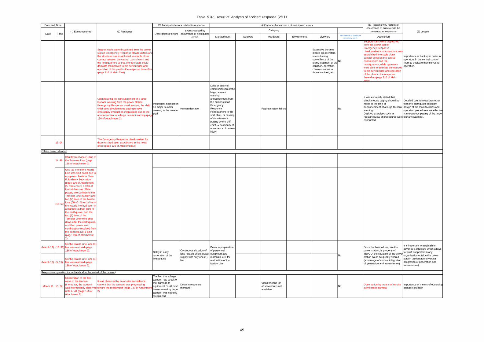
Table 5.3-1 result of Analysis of accident response (2/11)
Software
(1) Event occurred (2) Response
(4) Factors of occurrence of anticipated errors(3) Anticipated errors related to response
Liveware
Date and Time
DateCategoryEvents caused by
occurrence of anticipatederrors
TimeDescriptionEnvironment
Description of errorsHardware
(5) Reasons why factors ofoccurrence of errors could be
prevented or overcome
Occurrence of supposedsecondary causeManagement
(6) Lesson
Support staffs were dispatched from the powerstation Emergency Response Headquarters andthe structure was established to enable closecontact between the central control room andthe headquarters so that the operators coulddedicate themselves to the surveillance andoperation of the plant in the response thereafter(page 216 of Main Text).
Excessive burdensplaced on operatorsin conductingsurveillance of theplant, judgment of thesituation, operation,communication tothose involved, etc.
No.
Support staffs were dispatchedfrom the power stationEmergency ResponseHeadquarters and a structure wasestablished to enable closecontact between the centralcontrol room and theheadquarters, while operatorswere able to dedicate themselvesto the surveillance and operationof the plant in the responsethereafter (page 216 of MainText).
Importance of backup in order foroperators in the central controlroom to dedicate themselves tooperation.
Upon hearing the announcement of a largetsunami warning from the power stationEmergency Response Headquarters, the shiftchief used simultaneous paging to giveemergency evacuation instructions due to theannouncement of a large tsunami warning (page136 of Attachment 2).
Insufficient notificationon major tsunamiwarning to the on-sitestaff
Human damage
Lack or delay ofcommunication of thelarge tsunamiwarningannouncement fromthe power stationEmergencyResponseHeadquarters to theshift chief, or missingof simultaneouspaging by the shiftchief possibility ofoccurrence of humaninjury.
Paging system failure No.
It was expressly stated thatsimultaneous paging should bemade at the time ofannouncement of a large tsunamiwarning.Desktop exercises such asregular review of procedures wereconducted.
Detailed countermeasures otherthan the earthquake-resistantdesign of the main facilities andoperation procedures are effective(simultaneous paging of the largetsunami warning).
15:06The Emergency Response Headquarters fordisasters had been established in the headoffice (page 126 of Attachment 2).
14:48Shutdown of one (1) line ofthe Tomioka Line (page136 of Attachment 2)
(15:50)
One (1) line of the IwaidoLine was shut down due toequipment faults in Shin-Fukushima Substation(page 136 of Attachment2). There were a total offour (4) lines as offsitepower; two (2) lines of theTomioka Line (500kV) andtwo (2) lines of the IwaidoLine (66kV). One (1) line ofthe Iwaido line had been ina planned outage prior tothe earthquake, and thetwo (2) lines of theTomioka Line were shutdown after the earthquake,and then power wascontinuously received fromthe Tomioka No. 1 Line(page 136 of Attachment2).
(March 12) (13:38)On the Iwaido Line, one (1)line was restored (page136 of Attachment 2).
(March 13) (5:15)On the Iwaido Line, one (1)line was restored (page136 of Attachment 2).
March 11 15:22
Observation of the firstwave of the tsunami(thereafter, the tsunamiwas intermittently observeduntil 17:44 (page 126 ofAttachment 2).
It was observed by an on-site surveillancecamera that the tsunami was progressingtoward the breakwater (page 137 of Attachment2).
The fact that a largetsunami has struck orthat damage toequipment could havebeen caused by largetsunami was not fullyrecognized.
Delay in responsethereafter
Visual means forobservation is notavailable.
No.Observation by means of on-sitesurveillance camera
Importance of means of observingdamage situation
Delay in earlyrestoration of theIwaido Line
Continuous situation ofless reliable offsite powersupply with only one (1)line.
Delay in preparationof personnel,equipment andmaterials, etc. forrestoration of theIwaido Line.
No.
It is important to establish inadvance a structure which allowsfor swift support from anyorganization outside the powerstation (advantage of verticalintegration of generation andtransmission).
Since the Iwaido Line, like thepower station, is property ofTEPCO, the situation of the powerstation could be quickly shared(advantage of vertical integrationof generation and transmission).
Offsite power situation
Responsive operation immediately after the arrival of the tsunami
49
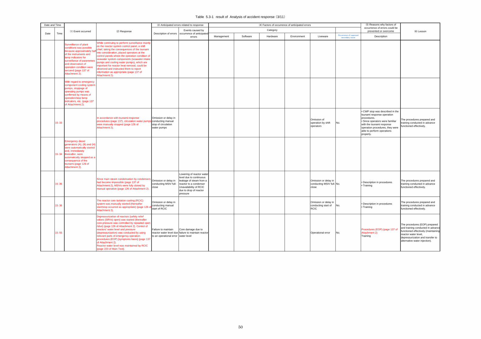
Table 5.3-1 result of Analysis of accident response (3/11)
Software
(1) Event occurred (2) Response
(4) Factors of occurrence of anticipated errors(3) Anticipated errors related to response
Liveware
Date and Time
DateCategoryEvents caused by
occurrence of anticipatederrors
TimeDescriptionEnvironment
Description of errorsHardware
(5) Reasons why factors ofoccurrence of errors could be
prevented or overcome
Occurrence of supposedsecondary causeManagement
(6) Lesson
Surveillance of plantconditions was possiblebecause approximately halfof the instruments andlamp indicators forsurveillance of parametersand observation ofoperation condition weresecured (page 137 ofAttachment 2).
While continuing to perform surveillance mainlyon the reactor system control panel, a shiftchief, taking the consequences of the tsunamiinto consideration, placed operators at thecontrol panels where the operation condition ofseawater system components (seawater intakepumps and cooling water pumps), which areimportant for reactor heat removal, could beobserved and instructed them to reportinformation as appropriate (page 137 ofAttachment 2).
With regard to emergencycomponent cooling systempumps, stoppage ofoperating pumps wasconfirmed by means ofoperation/stop lampindicators, etc. (page 137of Attachment 2).
15:33
In accordance with tsunami responseprocedures (page 137), circulation water pumpswere manually stopped (page 126 ofAttachment 2).
Omission or delay inconducting manualstop of circulationwater pumps
Omission ofoperation by shiftoperators
No.
• CWP stop was described in thetsunami response operationprocedures.• Since operators were familiarwith the tsunami responseoperation procedures, they wereable to perform operationsproperly.
The procedures prepared andtraining conducted in advancefunctioned effectively.
15:34
Emergency dieselgenerators (A), (B) and (H)were automatically startedand, immediatelythereafter, wereautomatically stopped as aconsequence of thetsunami (page 126 ofAttachment 2).
15:36
Since main steam condensation by condensershad become impossible (page 137 ofAttachment 2), MSIVs were fully closed bymanual operation (page 126 of Attachment 2).
Omission or delay inconducting MSIV full-close
Lowering of reactor waterlevel due to continuousleakage of steam from areactor to a condenserUnavailability of RCICdue to drop of reactorpressure
Omission or delay inconducting MSIV full-close
No.• Description in procedures• Training
The procedures prepared andtraining conducted in advancefunctioned effectively.
15:36
The reactor core isolation cooling (RCIC)system was manually started (thereafterstart/stop occurred as appropriate) (page 126 ofAttachment 2).
Omission or delay inconducting manualstart of RCIC
Omission or delay inconducting start ofRCIC
No.• Description in procedures• Training
The procedures prepared andtraining conducted in advancefunctioned effectively.
15:55
Depressurization of reactors (safety reliefvalves (SRVs) open) was started (thereaftercore pressure was controlled by repeated open/shut) (page 126 of Attachment 2). Control ofreactors’ water level and pressure(depressurization) was conducted by usingrelevant parts of emergency operationprocedures (EOP) [symptoms basis] (page 137of Attachment 2).Reactor water level was maintained by RCIC(page 220 of Main Text).
Failure to maintainreactor water level dueto an operational error
Core damage due tofailure to maintain reactorwater level
Operational error No.Procedures (EOP) (page 137 ofAttachment 2)Training
The procedures (EOP) preparedand training conducted in advancefunctioned effectively (maintainingreactor water level,depressurization and transfer toalternative water injection).
50

Table 5.3-1 result of Analysis of accident response (4/11)
Software
(1) Event occurred (2) Response
(4) Factors of occurrence of anticipated errors(3) Anticipated errors related to response
Liveware
Date and Time
DateCategoryEvents caused by
occurrence of anticipatederrors
TimeDescriptionEnvironment
Description of errorsHardware
(5) Reasons why factors ofoccurrence of errors could be
prevented or overcome
Occurrence of supposedsecondary causeManagement
(6) Lesson
15:57
Circulation water pumps(A) and (B) wereautomatically stopped(page 126 of Attachment2).
March 11
As it was not possible to start the residual heatremoval (RHR) system, which has functions toinject water to cool reactors and for heatremoval after the depressurization of a reactor,because emergency component cooling systempumps were unavailable as a consequence ofthe tsunami, in order to prepare for waterinjection cooling to reactors after stoppingRCIC, preparation of an alternative waterinjection by means of make-up watercondensate (MUWC) system, which had beenintroduced as an accident management (AM)measure, was commenced (page 137 ofAttachment 2).Because the power to drive valves necessaryfor configuration of line was lost as aconsequence of the tsunami, manual openingoperation was conducted on site. Afterconfiguration of line was completed, injectionvalves were opened from the central controlroom, and then water injection capability wasconfirmed (page 138 of Attachment 2).
Configuration ofalternative waterinjection by means ofMUWC could not havebeen completed beforeRCIC becameunavailable.
Core damage due tofailure to maintain reactorwater level
Description of lineconfiguration is notarranged as in theprocedures.
No.Line AM guidance proceduresprepared as a measure againstAM
Alternative water injection bymeans of MUWC, which had beenintroduced as an accidentmanagement measure, functionedeffectively.
17:35
Because the possibility of reactor coolantleakage in reactor containment vessels couldnot be denied, it was judged that the specifiedevent pursuant to Item 1 of Article 10 of the Acton Special Measures Concerning NuclearEmergency Preparedness had occurred, andaccordingly, it was reported to the competentauthorities, etc. at 17:55.It was later judged that it did not correspond tosuch specified event (page 126 of Attachment2).
17:53
The drywell (D/W) cooling system was manuallystarted (page 126 of Attachment 2).With the expectation of causing suppressionagainst the pressure increase of PCV, D/Wcooling system (no cooling source) wasmanually started. A drop in D/W temperaturewas observed immediately after the start, andthis information was reported to the Unit 3 andUnit 4 shift chiefs. Following this, said shiftchiefs conducted similar response andobserved a drop in D/W temperature (page 138of Attachment 2).
D/W cooling system isunavailable due to lossof offsite power.
Loss of offsite power No. Offsite power was available.
18:33
Because of the failure to start the facility with thereactor heat removal function, it was judged thatthe specified event pursuant to Item 1 of Article10 of the Act on Special Measures ConcerningNuclear Emergency Preparedness hadoccurred and accordingly, it was reported tocompetent authorities, etc. at 18:49 (page 126of Attachment 2).
By means of SRV, reactor pressure wasgradually decreased to such pressure level thatwater injection by MUWC became possible(page 220 of Main Text).
March 12 0:00
Alternative water injection by means of MUWCwas started (page 127 of Attachment 2). Waterinjection to reactors using a combination ofRCIC and MUWC was started (page 216 ofMain Text)
MUWC is unavailable.Damage to MUWCsystem due toearthquake
Loss of offsite power No.
• It remained free fromearthquake damage thanks to theresistance capability of equipmentof MUWC, which was used for AMbut whose category ofearthquake-resistant design wasclassified as base load system.• Since offsite power wasavailable, it was possible to useMUWC.
The earthquake-resistant designfunctioned effectively.(Earthquake-resistant capability ofbase load equipment)
3:50Fast depressurization of reactors was started(page 127 of Attachment 2).
Maintaining of reactor water level and cooling of containment vessel
51

Table 5.3-1 result of Analysis of accident response (5/11)
Software
(1) Event occurred (2) Response
(4) Factors of occurrence of anticipated errors(3) Anticipated errors related to response
Liveware
Date and Time
DateCategoryEvents caused by
occurrence of anticipatederrors
TimeDescriptionEnvironment
Description of errorsHardware
(5) Reasons why factors ofoccurrence of errors could be
prevented or overcome
Occurrence of supposedsecondary causeManagement
(6) Lesson
4:56Fast depressurization of reactors wascompleted (page 127 of Attachment 2).
4:58
RCIC was manually isolated in order todecrease steam pressure to drive the RCICturbine in association with reactor pressure dropwhile maintaining conditions under which it waspossible to maintain the reactor water level byMUWC (page 220 of Main Text).As a result, it was possible to maintain thereactor water level as high as the normal waterlevel and switch-over to water injection by lowpressure system could be made seamlessly(page 220 of Main Text).After this, the reactor water level was controlledonly by MUWC (page 127 of Attachment 2)(page 216 of Main Text).
Occurrence of blankperiod during whichwater level could notbe maintained by RCICor MUWC due to anoperational error
Core damage due tofailure to maintain reactorwater level
An operational error No.
• Procedures were well prepared.• Training was conducted.• Personnel were dispatched andassigned to communicate with theEmergency ResponseHeadquarters so that shiftoperators could dedicatethemselves to operation.
• Procedures prepared andtraining conducted in advancefunctioned effectively.• Importance of backup so thatoperators in the central controlroom can dedicate themselves tooperation.
5:22
Because temperature and pressure insuppression chamber (S/C) rose due to RCICexhaust and reactor depressurization by SRV(page 127 of Attachment 2) and thetemperature in S/C rose to no less than 100C,it was judged that this was an event to whichArticle 15 of the Act on Special MeasuresConcerning Nuclear Emergency Preparedness(loss of suppression function) applies (page 217of Main Text).
6:20
The power station Emergency ResponseHeadquarters investigated measures andmethods for cooling of S/C. A shift chiefinstructed operators to utilize the discharge linefrom FCS coolers to S/C and conduct cooling ofS/C by MUWC or MUWP in accordance with theinstructions given by the headquarters (page138 of Attachment 2).S/C cooling was conducted by using flammablegas control system (FCS) cooling water(MUWC) (page 127 of Attachment 2).
7:10Drywell spray was conducted using MUWC(thereafter conducted as appropriate) (page 127of Attachment 2).
Omission or delay inconducting drywellspray
Reaching maximumoperating pressure ofdrywell due to omissionof temporary suppressionof temperature andpressure, or conductingcontainment vessel vent
Hesitating to conductdrywell spray fromthe viewpoint ofproperty protection
No.The sense of making safety thefirst priority was thoroughly kept inmind.
Alternative water injection to reactors by MUWCwas switched to drywell spray and S/C spray asappropriate and efforts to suppress PCVpressure increase were conducted (page 138 ofAttachment 2).
Drywell and S/C spray by means of MUWC wasintroduced as one of measures for accidentmanagement and reflected in EOP (page 217 ofMain Text).
Oversight of D/Wand/or S/C sprayoperation by means ofMUWC
Oversight of D/Wand/or S/C sprayoperation by meansof MUWC
No.Procedures were reflected inEOP.Training
• Procedures prepared in advancefunctioned effectively.
7:37S/C spray was conducted using MUWC (page127 of Attachment 2).
7:45
The Prime Minister directedpeople in the zone within 3km from the power stationto evacuate and people inthe zone within 10 kmtherefrom to remainindoors (page 127 ofAttachment 2).
7:45
S/C cooling using FCScooling water was stopped(page 127 of Attachment2).
52

Table 5.3-1 result of Analysis of accident response (6/11)
Software
(1) Event occurred (2) Response
(4) Factors of occurrence of anticipated errors(3) Anticipated errors related to response
Liveware
Date and Time
DateCategoryEvents caused by
occurrence of anticipatederrors
TimeDescriptionEnvironment
Description of errorsHardware
(5) Reasons why factors ofoccurrence of errors could be
prevented or overcome
Occurrence of supposedsecondary causeManagement
(6) Lesson
March 12 10:21
Configuration of PCV pressure-proof vent-linewas commenced (page 127 of Attachment 2). Incontrast to containment vessel pressure-proofvent after core damage under accidentmanagement, this is done for the purpose ofdecreasing pressure that has risen incontainment vessels by releasing steam, etc.through pools in suppression chambers whilemaintaining the integrity of the core throughcontinuous water injection to reactors in thecase that there is delay in restoration of reactorheat removal function (page 217 of Main Text).
It was recognized by the power stationEmergency Response Headquarters that PCVpressure tended to rise because the plantparameters, such as reactor water level andD/W pressure, could be obtained throughcommunication with the central control room(PHS) (page 139 of Attachment 2).
Delay incommencement ofpreparation for vent
Vent cannot beconducted whennecessary.(As for results, it neverreached the pressureunder which vent shouldhave been required.)
・Cannot recognizethat preparation forvent takes muchmore time thanexpected.・Cannot understandthe risk resulting fromthe delay of RHRrecovery efforts.
Delay of RHRrecovery efforts
No.
・Because preparation for venttook much more time thanexpected at the Fukushima Daiichinuclear power plant, the headoffice recommended earlierpreparation for vent. TheHeadquarters at 2F was alsoaware of the necessity of ventpreparation.・RHR recovery efforts wentsmoothly.
Importance of establishing a planwith foreseeability.
Anticipating that it would take time to restorereactor heat removal function, it was determinedthat configuration of the line for the PCVpressure-proof vent (the condition that oneaction of opening operation an exit valve at S/Cside remained untaken) should be conducted(page 139 of Attachment 2).
Because the power for pressure-proof vent-lineinlet valve- (air controlled valves) drivenelectromagnetic valves for air control was lost,the opening operation could not be conducted.The power station Emergency ResponseHeadquarters, therefore, investigatedcountermeasures (a method of connecting asmall cylinder directly to the valve driving part ora method of performing the opening operationby restoring power to such electromagneticvalve), judged that there should be a timemargin in view of the trend of PCV pressurerising, and determined that the openingoperation should be conducted by restoringpower to such electromagnetic valve (page 139of Attachment 2).
14:05
It was confirmed that thegovernment’s evacuationaction of evacuatedresidents had beencompleted.
17:39
The Prime Minister directedthe population in the zonewithin 10 km fromFukushima Daini NuclearPower Station to evacuate(page 127 of Attachment2).
18:30Configuration of PCV pressure-proof vent-linewas completed (page 127 of Attachment 2).
(March 13) Drywell pressure wasgradually rising due to lossof the function to removeheat from reactors, and itreached design pressure(0.38 MPa [abs]) on thethird day, but neverreached maximumoperating pressure (0.41MPa [abs]) (page 220 ofMain Text).
Preparation of PVC pressure-proof vent
53

Table 5.3-1 result of Analysis of accident response (7/11)
Software
(1) Event occurred (2) Response
(4) Factors of occurrence of anticipated errors(3) Anticipated errors related to response
Liveware
Date and Time
DateCategoryEvents caused by
occurrence of anticipatederrors
TimeDescriptionEnvironment
Description of errorsHardware
(5) Reasons why factors ofoccurrence of errors could be
prevented or overcome
Occurrence of supposedsecondary causeManagement
(6) Lesson
(March 11)
The power station Emergency ResponseHeadquarters examined the situation of damageto the facility through site observation and madea plan for restoration strategy and prioritizationof works (page 217 of Main Text).
Omission of prioritizingrestoration worksamong units
Delay in restoration ofplant, which is of highpriority
Failure to performprioritization
No.
The plant data which had beenregularly collected by the centralcontrol room were arranged intotrends by the EmergencyResponse Headquarters,containment vessel pressurerising trends were monitored, thetime when rupture disk pressurewould reach setting pressure wasestimated, and then prioritizationamong units was determined.
Importance of early planning andarrangement of materials basedon site observation.
It was, however, unable to dispatch arestoration team to the site immediatelybecause the situation of the site was such thatno lighting was available, extensive debris andopenings posed danger, the paging systemcould not be used as a means ofcommunication for evacuation at the time oftsunami striking under continuousannouncement of after-shocks and largetsunami warnings and in addition, PHS could notbe used in the buildings damaged by thetsunami (page 217 of Main Text).
During site observation at Hx/B, desperateefforts to examine the damage situation weremade, relying only on a small number offlashlights available in the unlit darkness, beingsubmerged into pool of water made by thetsunami and clearing over debris and waste,and, repeatedly evacuating to high ground atevery after-shock while tsunami warnings werecontinuously announced (page 139 ofAttachment 2).
(Around22:00)
It was around 22:00 on March 11 when arestoration team commenced examination ofthe damaged site, such as a seawater heatexchanger building near the sea coast, etc. afterhaving established a means of communication,using messengers, with regard to sheltering andhaving prepared safety equipment.
March 12
Based on site examination results given by therestoration team (conditions of equipment andsituation of flooding of power system (page 139of Attachment 2)), the power station EmergencyResponse Headquarters determined the policythat priority should be given to conductingrestoration works for residual heat removalcomponent cooling pump (D), residual heatremoval seawater pump (B) and emergencydiesel generator facility cooling system pump(B) in the seawater heat exchanger building(page 217 of Main Text).Regarding residual heat removal componentcooling pump (D) and emergency dieselgenerator facility cooling system pump (B), thepolicy that motors should be replaced wasdetermined (page 217 of Main Text).
• Fault in observationof site situation• Omission ofprioritizing restorationworks
Delay in restorationworks due toestablishment of anincorrect wrongrestoration policy
Omission ofprioritizing restorationworks due toabsence ofgovernance of thepower stationEmergencyResponseHeadquarters
• Deterioration ofenvironment of thelocation of the powerstation EmergencyResponseHeadquarters(scattering offurnishings, etc.)• Failure to take outdrawings to be usedfor restoration worksas a consequence ofthe earthquake
Deficiency in skills toobserve the situationof the facility inquestion
No.
•Available equipment (pumps)was selected based on the resultsof site observation, and theseresults were indicated in a matrix,and priority equipment to berepaired in order to restore theheat removal function wereselected.• Adequate judgment of the powerstation Emergency ResponseHeadquarters• Routine skill concerning repair ofsuch facility・The seismic isolation buildingwas effective although it lost thepower for 2 to 3 hours due to thetsunami.• Countermeasures had beentaken for racks for documents inan office building based on theexperiences of the 2007 ChuetsuOffshore Earthquake, anddocuments could be taken out.
• Importance of sharinginformation• Importance of the power stationEmergency ResponseHeadquarters grasping thesituation (situation of damage toequipment)• Importance of the power stationEmergency ResponseHeadquarters establishing anadequate response strategy(prioritization of restoration)• The important anti-seismicbuilding functioned effectively.• Careful consideration with regardto earthquakes is effective (fixingfurnishings, etc.)
Urgent procurement of motors was requested toKashiwazaki Kariwa Nuclear Power Station.Kashiwazaki Kariwa Nuclear Power Stationgave proactive assistance in procuring theequipment and materials required by FukushimaDaiichi and Fukushima Daini Nuclear PowerStations (page 217 of Main Text).
Delay in support fromthe side ofKashiwazaki KariwaNuclear Power Station
Delay in restorationDelay in establishingcooperation acrossorganizations
Poor communicationfor mutualunderstandingbetweenorganizations(communication formutual confirmationof usable motormodels, etc.)
No.
Kashiwazaki Kariwa NuclearPower Station, which is anorganization within the samecompany, also participated in avideo conference and shared thesituation of Fukushima Daini.
Importance of establishing inadvance a structure to allow forswiftly receiving support fromoutside of the power station(Importance of sharing thesituation in order to swiftly receivenecessary support from the othernuclear power stations)
Delay in establishing arestoration plan due todelay in observation ofsite situation
Means ofcommunicationunavailable at site.
Restoration of residual heat removal system
• No lighting at site• Dangerousenvironment due toexistence ofextensive debris andopenings
Fear of the tsunamistriking again duringsite observation
Yes.
• Sense of responsibilityovercoming fear• A means to communicate aboutsheltering was established byarranging messengers accordingto circumstances, etc.
Further delay in siteobservation
• Importance of overcoming fearwith a strong sense of mission torestore after an accident• Establishment ofcountermeasures and animplementation structure toperform the countermeasures bythe power station EmergencyResponse Headquartersaccording to circumstances• Preparation of portabletemporary lighting
54

Table 5.3-1 result of Analysis of accident response (8/11)
Software
(1) Event occurred (2) Response
(4) Factors of occurrence of anticipated errors(3) Anticipated errors related to response
Liveware
Date and Time
DateCategoryEvents caused by
occurrence of anticipatederrors
TimeDescriptionEnvironment
Description of errorsHardware
(5) Reasons why factors ofoccurrence of errors could be
prevented or overcome
Occurrence of supposedsecondary causeManagement
(6) Lesson
Delay in orders ofmotors frommanufacturers
Delay in restoration
Delay in locatingmotorsDelay in response bycontractors
No.
• A procurement list had beenprepared in advance.• Good business relationships hadbeen established; even thoughrequests were only made bytelephone, contractors madequick responses favorably.
Importance of establishing inadvance a structure to allow forswiftly receiving support fromoutside of the power station(Preparation of procurementsources of necessary equipmentand materials and informationabout availability in advance)
Delay in transportationof motors
Delay in restoration
Delay in longdistance (from MiePrefecture toFukushima)transportation due todeterioration of roadtraffic conditions dueto earthquakedamage
No.
• Transportation by a Self-Defense Forces transport plane• The head office’s EmergencyResponse Headquarters fordisasters made a request to theSelf-Defense Forces.
Importance of establishing inadvance a structure to allow forswiftly receiving support fromoutside of the power station(Importance of swift support ofgovernment organizations)
The power station Emergency ResponseHeadquarters requested from the head officethe urgent procurement of high voltage powersource cars, portable transformers and cablesin order to connect motors with power panelsremaining free from the consequences of thetsunami and power source cars, because powerpanels supplying power to motors of pumps hadlost function due to flooding (page 217 of MainText).
Delay in support fromthe side of the headoffice
Delay in restorationDelay in establishingcooperation acrossorganizations
Poor communicationfor mutualunderstandingbetweenorganizations(communication formutual confirmationof necessaryequipment andmaterials, etc.)
No.
• The head offices’ EmergencyResponse Headquarters fordisasters also had control overorganizations within the samecompany outside the nuclearpower division (advantage ofvertical integration of generationand transmission).• Corporate-wide emergencyresponse manual
Importance to establish inadvance a structure to allow forswiftly receiving support fromoutside of the power station(Advantage of utilities verticalintegration of generation andtransmission)
Among the power panels which were availableand remained free from the consequences ofthe tsunami, it was determined that a powerpanel in a radioactive waste treatment buildingshould be used. The reason why the panel in theradioactive waste treatment building, which wasthe farthest from the seawater heat exchangerbuilding, was chosen was that since there wouldbe fewer complicated cabling works and mostrouting would run on the ground along a straightroad, it would be appropriate for laying heavyand hard cables manually. This was thejudgment made by a restoration team based onthe actual situation of the site (page 218 of MainText).
Selection of otherrouting for cablingworks
Delay in restoration ofpower
Poor conduct intaking up the opinionsof each teammember within theteam
No understanding ofactual situation ofmanual cabling works
No.
There was the capability torespond according tocircumstances to suchunexpected events, such as thecase of manual cabling works.• Understanding of cabling worksobtained through routinemaintenance• Calm judgment within the team
Importance of establishing anadequate response policy• (Proper selection of routing forcabling works)• (Adequate judgment made by aleader of the power stationEmergency ResponseHeadquarters based on properimplementation of function byeach team and information and/oropinions properly taken up fromeach team)
The equipment and materials which the headoffice had been requested to procure arrivedone after another at Fukushima Daini by around6:00 on March 13. Incidentally, transportationtook longer than expected as a consequence ofmobile phones being unavailable between thepower station Emergency ResponseHeadquarters and the transportation team, etc.(page 218 of Main Text).
Unavailability of adriver for a large trailerto transport heavycargoes to the powerstation, includingcargoes from placesother than Kashiwazaki
Refusal by drivers ofcompanies to whichtransportation wasoutsourced to enterthe controlledevacuation area
Partially occurred.
• Transportation by drivers withlicenses to drive large vehiclesbelonging to TEPCO subsidiariesand subcontractors working in thepower station• Transportation by governmentalemergency responseorganizations such as Self-Defense Forces
• Appointment of drivers withlicenses for large vehicles asemergency personnel• Advance preparation of astructure to allow for receivingsupport from the Self-DefenseForces and so on more thoroughly(preparatory radioactive educationto be provided for Self-DefenseForces personnel, etc.)
It was decided that temporary cables would betransported from outside by helicopter. It washurriedly decided that a field or a baseball fieldwould be used as a heliport, and works toprepare to receive cargo were conductedovernight; the fence around the baseball groundwas removed before dawn on March 12 andtwenty (20) cars owned by employees werearranged for lighting to guide helicopter landing.Under bad road conditions resulting from theearthquake, car transportation was alsoarranged (page 139 of Attachment 2).
• Delay in preparing toreceive, such asguiding lighting, etc.
Delay in restoration ofpower
Delay in establishingpreparedness toreceive, such asguiding lighting, etc.
No.
Governance of the power stationEmergency ResponseHeadquarters functionedeffectively.
Establishment of a plan forcountermeasures according tocircumstances in line with thesituation of the site and astructure for the implementation ofthe countermeasures
The total length of temporary cables amountedto as much as 9 km for the four units of theplant. Laying works for these cables werecompleted manually by as many as 200personnel, including employees from thedistribution division and workers ofsubcontractors no later than around 23:30 onMarch 13 (page 218 of Main Text).
• Head office EmergencyResponse Headquarters hadcontrol over divisions other thanNuclear Power Division in thesame company (advantage ofvertical integration of utilities).• Mass procurement of cables,
Regarding motors for some of the emergencycomponent cooling system pumps of Unit 1,insulation resistance could not be recovered inspite of cleaning the motors. Therefore, motorswere transported from Mie Prefecture toFukushima Airport by a Self Defense Forcestransport plane. As soon as they arrived at thesite, installation and connection with temporarycables were commenced immediately and werecompleted by the evening of March 13 (page140 of Attachment 2).
55

Table 5.3-1 result of Analysis of accident response (9/11)
Software
(1) Event occurred (2) Response
(4) Factors of occurrence of anticipated errors(3) Anticipated errors related to response
Liveware
Date and Time
DateCategoryEvents caused by
occurrence of anticipatederrors
TimeDescriptionEnvironment
Description of errorsHardware
(5) Reasons why factors ofoccurrence of errors could be
prevented or overcome
Occurrence of supposedsecondary causeManagement
(6) Lesson
For the cabling works, several combined teamsconsisting of 40 personnel including employeesand workers of on-site subcontractors as well aspersonnel from the distribution division of eachbranch office (employees and subcontractors)were formed, and works were conducted asafter-shocks occurred and debris was scatteredaround as a consequence of the tsunami. Theworks were conducted at nighttime, relying onhead lights since it was completely dark (page140 of Attachment 2).
Temporary cables were made up of a packageof three (3) 2-3 cm thick wires twisted, and one(1) 200 m long cable weighed no less than 1 t.It was required that the cable be laid as long asapproximately 800 m from the RW building toHx/B. Under normal conditions, the work shouldhave been conducted by machine over thecourse of several days; this time, however, theworks were conducted manually at a very highpace and the cabling work for total extension ofapproximately 9 km was partly completed onMarch 12 and mostly completed on March 13(page 140 of Attachment 2).
Based on continuous surveillance andestimation of plant data (containment vesselpressure) made by a technical team of thepower station Emergency ResponseHeadquarters, first priority was originally givento the cabling work for Unit 2, of whichcontainment vessel pressure had been risingfastest. Since, however, it was discoveredbefore dawn on March 13 that the containmentvessel pressure of Unit 1 was rising faster thanthat of Unit 2, the priority of cabling work waschanged to Unit 1 (page 218 of Main Text).
• Omission ofprioritization of cablingworks among units• Mistake in selectionof priority unit forcabling works
Unit 1 drywell pressurereaches maximumoperating pressure, orcontainment vessel ventshall be conducted.
Omission ofprioritization ofcabling works amongunits due to absenceof governance in thepower stationEmergencyResponseHeadquarters
A team in charge ofsurveillance andestimation of plantdata is not clearlyidentified.
• Governance of the power stationEmergency ResponseHeadquarters• Clear identification of division ofthe roles and tasks to beperformed by each team(technical team) of the powerstation Emergency ResponseHeadquarters
Importance of the power stationEmergency ResponseHeadquarters establishing anadequate policy for response• (Prioritization of cabling worksamong units)• (Adequate judgment made by aleader of the power stationEmergency ResponseHeadquarters based on properimplementation of function byeach team, and information and/oropinions properly taken up fromeach team)
Observation of condition of mechanical parts forpumps and installation of motors wereconducted in parallel with the cabling works(page 218 of Main Text)
Delay in works Delay in restorationNecessary personnelcannot be arranged.
Not only personnelfor emergencyresponse consistingof employees (200employees) but alsosubstantially almostall employees(approximately 400employees) andmany of thesubcontractors’employees(approximately 1,900employees) remainedat the power stationfor emergencyresponse. Therefore,there was a greatershortage of rationsfor personnel thanexpected.
No skill for the works No.
• According to the manual foremergency disaster preventiveactivities, food for 250 personnelfor three (3) days and drinkingwater for 50 days. In addition,food for shift operators for 40days and food for 60% of officepersonnel for two (2) weeks hadbeen stocked ascountermeasures againstinfluenza A (H, N). This food wasdistributed to personnel at thepower station at the time of theearthquake disaster, and as aresult, demand was filled for three(3) days. On March 13, supportgoods from the other branchoffices arrived at the powerstation.• Preparedness of on-sitesubcontractors stationed at thepower station• Maintenance of each piece ofequipment had been continuouslyordered from the same company.
• Necessity to stock appropriateamounts of food and drinkingwater• Importance of establishing aroutine relationship with on-sitesubcontractors who providecooperation in case of emergency
Dispatched personnelrefuse to enter thesite declared anuclear emergencyevacuation area.
No.Necessary workerscannot be arranged.
Delay in restoration ofpower
• Divisions other thanthe Nuclear PowerDivision refuse todispatch personnel tothe site wherenuclear disaster hasoccurred, •Subcontractorshesitate to dispatchtheir employees tothe nuclearemergencyevacuation area.
Necessary stock ofequipment andmaterials is notavailable.
etc. was possible as the companywas a vertically integrated electricpower company includingdistribution and constructiondivisions.• Company loyalty: Divisions otherthan the Nuclear Power Divisionhad a strong will to stop thenuclear disaster.• The subcontractors’ sense thatthe plant belonged to them(preparedness of on-sitesubcontractors stationed at thepower station)• Regarding requests tocontractors for restoration works,the head office’s ProcurementDepartment had madeagreements with contractors andmanufacturers concerning supportand cooperation in case of“emergency disasters” and“emergency events.” Within thisframework, special cooperationcould be requested.
• Importance of establishing inadvance a structure to allow forreceiving swift support fromorganizations outside the powerstation (advantage of utilities withrespect to vertical integration ofgeneration and transmission).• Importance of establishing aroutine relationship with on-sitesubcontractors who providecooperation in case of emergency
56
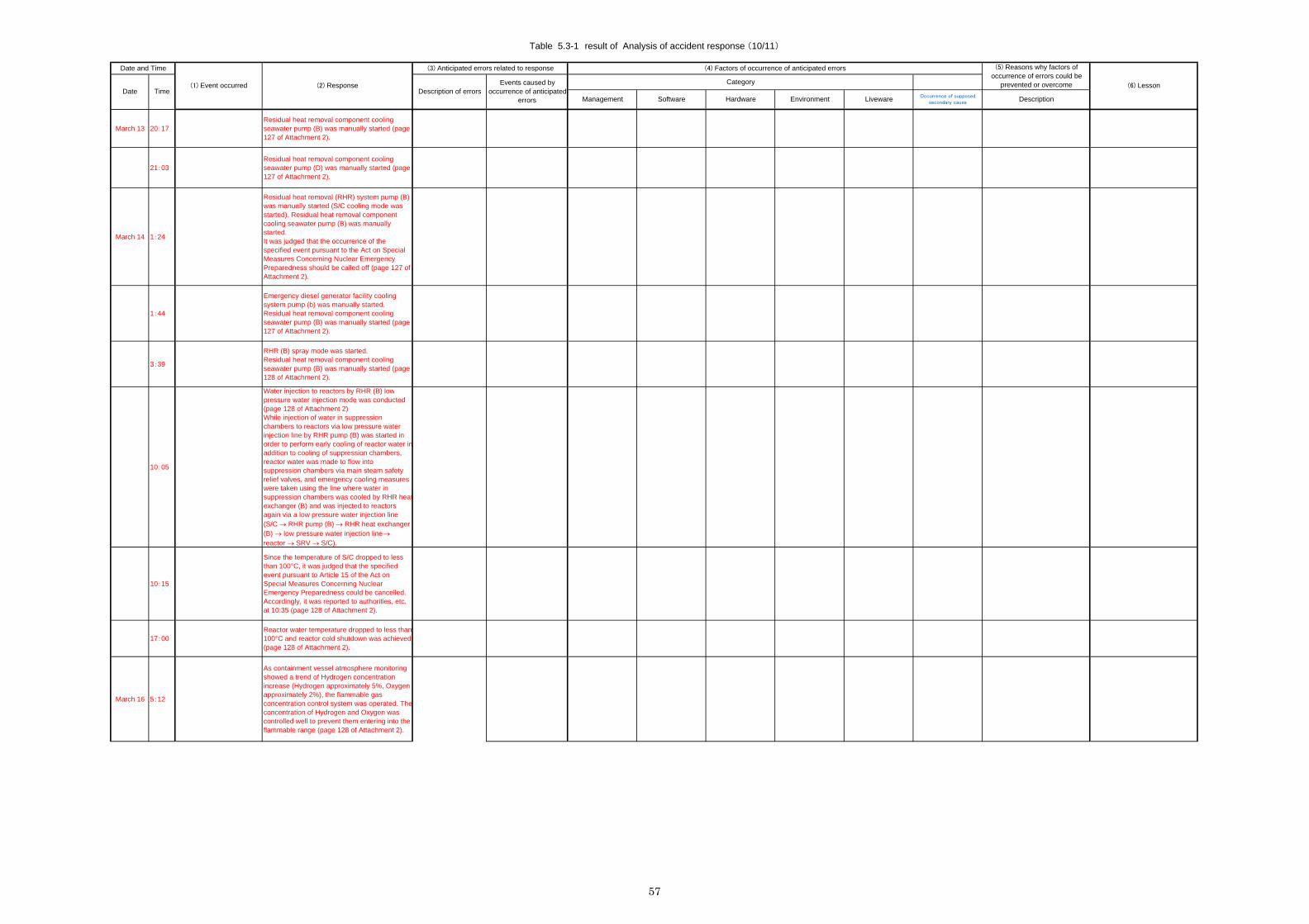
Table 5.3-1 result of Analysis of accident response (10/11)
Software
(1) Event occurred (2) Response
(4) Factors of occurrence of anticipated errors(3) Anticipated errors related to response
Liveware
Date and Time
DateCategoryEvents caused by
occurrence of anticipatederrors
TimeDescriptionEnvironment
Description of errorsHardware
(5) Reasons why factors ofoccurrence of errors could be
prevented or overcome
Occurrence of supposedsecondary causeManagement
(6) Lesson
March 13 20:17Residual heat removal component coolingseawater pump (B) was manually started (page127 of Attachment 2).
21:03Residual heat removal component coolingseawater pump (D) was manually started (page127 of Attachment 2).
March 14 1:24
Residual heat removal (RHR) system pump (B)was manually started (S/C cooling mode wasstarted). Residual heat removal componentcooling seawater pump (B) was manuallystarted.It was judged that the occurrence of thespecified event pursuant to the Act on SpecialMeasures Concerning Nuclear EmergencyPreparedness should be called off (page 127 ofAttachment 2).
1:44
Emergency diesel generator facility coolingsystem pump (b) was manually started.Residual heat removal component coolingseawater pump (B) was manually started (page127 of Attachment 2).
3:39
RHR (B) spray mode was started.Residual heat removal component coolingseawater pump (B) was manually started (page128 of Attachment 2).
10:05
Water injection to reactors by RHR (B) lowpressure water injection mode was conducted(page 128 of Attachment 2)While injection of water in suppressionchambers to reactors via low pressure waterinjection line by RHR pump (B) was started inorder to perform early cooling of reactor water inaddition to cooling of suppression chambers,reactor water was made to flow intosuppression chambers via main steam safetyrelief valves, and emergency cooling measureswere taken using the line where water insuppression chambers was cooled by RHR heatexchanger (B) and was injected to reactorsagain via a low pressure water injection line(S/C RHR pump (B) RHR heat exchanger(B) low pressure water injection line reactor SRV S/C).
10:15
Since the temperature of S/C dropped to lessthan 100°C, it was judged that the specifiedevent pursuant to Article 15 of the Act onSpecial Measures Concerning NuclearEmergency Preparedness could be cancelled.Accordingly, it was reported to authorities, etc.at 10:35 (page 128 of Attachment 2).
17:00Reactor water temperature dropped to less than100°C and reactor cold shutdown was achieved(page 128 of Attachment 2).
March 16 5:12
As containment vessel atmosphere monitoringshowed a trend of Hydrogen concentrationincrease (Hydrogen approximately 5%, Oxygenapproximately 2%), the flammable gasconcentration control system was operated. Theconcentration of Hydrogen and Oxygen wascontrolled well to prevent them entering into theflammable range (page 128 of Attachment 2).
57

Table 5.3-1 result of Analysis of accident response (11/11)
Software
(1) Event occurred (2) Response
(4) Factors of occurrence of anticipated errors(3) Anticipated errors related to response
Liveware
Date and Time
DateCategoryEvents caused by
occurrence of anticipatederrors
TimeDescriptionEnvironment
Description of errorsHardware
(5) Reasons why factors ofoccurrence of errors could be
prevented or overcome
Occurrence of supposedsecondary causeManagement
(6) Lesson
The increase of Hydrogen concentration isconsidered as follows:It is possible that before cold shutdown, anoxidization reaction of zinc (paint, etc.) and soon in the containment vessel could haveoccurred under conditions of radiolysis and hightemperature and humidity. It is also consideredto be possible that after the cold shutdown, anoxidization reaction of zinc and so on could havecontinued partially even though the temperatureof the containment vessel dropped.In addition, it is estimated that under pre-coldshutdown conditions, the dehumidifier forcontainment vessel atmosphere monitoringcould not have functioned due to the loss ofcooling sources, and since sample gastemperature and humidity exceeded serviceconditions, it deviated from the measurements.After cold shutdown, however, sample gasdehumidifier function was recovered. It shouldbe remarked, however, that the reliability of theHydrogen concentration meter needsinvestigation (page 220 of Main Text).
A method of monitoring Hydrogenconcentration is being developedbased on the experiences inFukushima Daiichi.
March 11
The main administration office evacuated to theparking area that had been designated as anevacuation site, and conducted confirmation ofemployee safety.Emergency response personnel then moved tothe important anti-seismic building while otheremployees evacuated to a field (page 136 ofAttachment 2).
The safety of someemployees could notbe confirmed.
It is required to conductconfirmation of missingemployees in addition torestoration works, whichhas an adverse impacton the restoration works.
Failure to directevacuation to thedesignated place andconfirm personnelsafety
No.• There were provisions in themanual for emergency events.• Training was conducted.
Others
58

5.4 Important lessons obtained from the analysis
As a result of the analysis, the following points were obtained as important lessons. It is desirable that the contents of these lessons are also applied in other power plants as preparations for large-scale accidents.
① Appropriate governance of the response headquarters at the power plant.
Important features required in the on-site headquarters are as follows:
• An accurate understanding of the circumstances of the accident (plant parameters, status of damage of equipment).
• Each team of the headquarters shall fulfill the assigned tasks as shared among the teams.
• The conductor of the headquarters shall accurately pick up the opinions/information from each group and ensure that they are shared.
• Develop appropriate response strategy. (Example: making decisions on the recovery plan priority, appropriate routing of cable laying)
• For the implementation of individual response, create appropriate ad hoc measures in line with the situation at hand, and establish a proper framework for implementation. (Example: Establishing a reliable channel for communication with the patrolling team for the contingency of a tsunami warning.)
• Not only respond to the development of the event, but prepare proactive measures. (Example: line configuration in preparation for the containment vessel vent.)
② Establishment of a system to receive immediate assistance, supply of materials from external organizations.
For the restoration works of the residual heat removal system, equipment and materials such as motors usable for the residual heat removal system pump and a large amount of cables spanning 9 km were quickly procured from outside, and large number of personnel, including workers skilled in cable laying, were dispatched to help.
These quick arrangements can be attributed to following factors.
• The power company is vertically integrated to handle power generation and transmission, so the human resources for cable laying and equipments/materials such as cables were all available in the same company, making rapid procurement possible.
• The cooperating companies are stationed in the plant site, and a close relationship with them has been established on a day-to-day basis to facilitate cooperation in emergency situations. To ensure quick procurement of materials and equipment, development of the following is desirable:
• Maintaining a list of suppliers for a variety of equipment.
• Secure a driver with a license for large vehicles for carrying large and heavy equipment (for receiving the supply of cargo from companies which are not allowed to let their staff enter a nuclear disaster evacuation zone.)
• Support by government agencies including transportation of heavy and large cargo by SDF helicopters.
③ It is desirable to foster a culture of safety among all related personnel, including not only TEPCO employees but also the workers of cooperating companies, for the
59

purpose of strong determination and a sense of mission to achieve convergence in the event of an emergency, even in a hazardous environment such as high radiation dosing from the nuclear disaster caused by the tsunami due to the aftershocks.
④ Seismic design proved effective. As intended, equipment in the safety systems that have been installed with state-of-the-art seismic design worked without failure, even in ground motion. In addition, the equipment used for the conventional AM system (MUWC) also withstood ground motion beyond the design standard by its own margin and kept functioning without failure.
⑤ Maintenance of procedure and staff training in advance worked well. Among other factors, the most notable ones which enabled a variety of smooth and swift responses were that procedure manuals were prepared in advance and all the operating personnel and workers, being familiar with the procedures, responded appropriately according to the procedures as prescribed in the manuals.
⑥ The importance of the back-up structure to allow the operating staff of the central control room to concentrate on the operation of the reactor. The operating personnel of the central control room received overall support from the plant so as to be able to concentrate on the operation of the reactor. This included maintaining normal shifts, increasing the number of patrollers, dispatching liaisons for better communication, and centrally controlling contact with off-site entities by the emergency headquarters. Successful convergence of the accident can be attributed to these support systems.
⑦ Peripheral earthquake preparedness other than seismic design of facilities and equipment or emergency operating procedures was also effective. The plant already had variety of earthquake preparations in place from the Chuetsu-oki Earthquake, and these proved effective this time. Example: Fastening and fixing loose furniture in the main control room and offices, preparing temporary lighting and handheld microphones, etc.
60

6. Emergency response as seen from the viewpoint of the human factor
With respect to the emergency response at Fukushima Daini, some situations that actually occurred were not described in the manual or handled in the usual training drills, and so the capabilities of plant organizations and individuals to handle the situation were tested. In these difficult circumstances, their response was generally adequate and under good leadership, and it successfully prevented the spread of the accident, leading to convergence.
We have analyzed the background from the viewpoint of the human factor. Table 6-1 shows the results of analysis by the m-SHEL model. We also made analysis based on a method of analyzing the resilience of the organization. The results are shown in Table 6-2.
In terms of human factors, there were considered to be two major factors that contributed to the successful convergence of the accident: the appropriate management of the accident response, and the effectiveness of the various measures that had been prepared in advance.
In order to ensure the effectiveness of management, it is necessary that the senior management perform good leadership with sufficient knowledge, and the organization should be well disciplined, which requires ongoing efforts to establish a good work environment under normal circumstances.
Important areas that require advance preparation may be: establishment of an emergency system (including an external support system), maintenance of manuals, cultivation of a culture of safety, education and training, stockpiling of food, and installation of a seismic isolation building. These requirements also call for ongoing efforts under normal circumstances.
Some fortunate circumstances were observed in this accident, such as a single line of the external power supply remaining online by chance, there being relatively insignificant tsunami damage to some of the vital facilities, or accident convergence being achieved in a relatively short time. However, in preparing for future accidents, we must assume that we cannot expect these fortunate circumstances.
We also performed analysis focusing on the resilience of Fukushima Daini as an organization. We identified the good practices of the organization from four perspectives and concluded that the organization as a whole is well-balanced. Finding these good practices also indicated that the strength of the organization comes from ongoing efforts under normal circumstances (development of manuals and training). In addition, it is necessary that each and every member of personnel hold a strong sense of mission for safety. This serves as the foundation to support the strength of these organizations. We have been reminded once more that fostering a culture of safety is truly important.
61

Table 6-1 Human factors that contributed to the convergence of the accident
Management Software Hardware Environment Live ware
The pre- determined emergency system clearly defined role assignment. System established as soon as the earthquake hit and utilized effectively.
Senior management exercised strong and unperturbed leadership when making analysis for accurate instructions.
Intent of instructions clearly understood by all personnel through information sharing.
Action plans were prepared not only in response to actual event development but in the sense of proactive strategy.
A system to receive quick support from off- site was in place. Procurement of equipment and materials was reasonably quick.
A system was established so that operators in the central control room could concentrate on the operation of reactor.
Procedures prepared in anticipation of the main condenser being unusable as a heat sink.
Root contact was in place for mobilizing emergency response personnel.
Instructions were effective.
Restoration team dispatched patrol team after determining evacuation procedures in advance.
A video conference system was available with the head office and Kashiwazaki- Kari-wa. Multiple communication channels were available.
Important seismic isolation building functioned.
Power source remained functional.
RCIC was available thanks to only minor inundation by the tsunami.
Radiation management equipment was free of earthquake and tsunami damage, and was secured.
AM equipment was functional without failure, even for ground motion beyond the design intensity.
Outside disturbance was minimal and plant was mostly able to handle the situation at its discretion.
Earthquake occurred on a weekday afternoon and the emergency response system was smoothly established. (Necessary personnel swiftly secured)
Sufficient stockpile of drinking water and food was available.
Emergency response headquarters able to carry out operations at the important seismic isolation building.
A grip bar was available on the operation panel of the central operation room for operators to hold on to.
Cabinets were fastened and secured to prevent tripping.
Instruments remained functional, so the situation could be confirmed.
Proper lighting and communications were maintained, so the work environment was not significantly adverse.
Prospect of accident convergence foreseen in relatively short time.
Sufficient knowledge to predict the progress of events to plan effective countermeasures.
Operators performed adequate operations without mistakes.
In the event of an emergency, all personnel maintained a strong sense of mission to achieve convergence even in a hazardous environment. (Such psychological culture of safety was fostered at the plant.)
All personnel were well educated and trained to execute duties properly in accordance with instructions.
Some TEPCO employees had professional expertise in driving large vehicles.
62

Table 6-2 Analysis of the resilience of Fukushima Daini
Responding Monitoring Anticipating Learning
Equipment still in operating condition after the earthquake could be confirmed at the central operating room.
Personnel with operator experience were dispatched to the central operating room so that operating personnel could concentrate on operating the reactor.
An emergency system was immediately established after the earthquake.
A patrol team was quickly organized and dispatched to check conditions at site.
Recovery procedures were quickly prepared and each team began work after confirming tasks.
Dry well spray was conducted to cool the containment vessel.
Early arrangements for procurement of equipment and support of workers were initiated.
Operation of equipment was confirmed by the lamps in the central operating room.
Site patrol was conducted to check damage to equipment.
The main parameters of the plant were continuously monitored at the headquarters.
Information from each group was visually displayed on a white board to ensure sharing among all staff.
Smooth communication between each group and headquarters for close instructions and progress reports maintained through frequent and mutual reports, advice and consultations.
The integrity of the instruments was confirmed by monitoring the continuity of parameter variations.
Power source recovered quickly for the worst contingency of total loss of external power.
Recovery procedures were prepared based on plant situation and site patrol findings.
Prioritized recovery plan of units from the changes in parameter and executed in sequence.
Confirmed function of MUWC while RCIC was in operation.
A patrol team was dispatched to the scene only after evacuation procedures were established.
Procurement of equipment and material was arranged as far in advance as possible.
Daily rations of water and food were adjusted for possible prolongation of the situation.
Assuming the worst, containment vessel vent was prepared in advance.
A video conference system was available with the head office and Kashiwazaki-Kariwa. Multiple communication channels were available.
Based on the experience of the Chuetsu-oki earthquake, a variety of preparations were in place: installation of the important seismic isolation building, a grip bar on the operating panel of the central operation room, and securing of cabinets to prevent tripping.
A system was in place to receive quick support from off- site.
After examination based on the manual, a temporary cooling system configuration of RPV and S/C using one unit of RHR was devised as the operation to be applied.
Resilience: Capability of organization to ensure continuous success in the ever-changing circumstances.
Responding: Response to incident
Monitoring: Monitoring of development of incident
Anticipating: Anticipation of threats and opportunities
Learning: Learning from past success and failure
63

7. Lessons
Fukushima Daini’s accident response includes a variety of best practices in many aspects from which we can learn valuable lessons. In addition, since the impact of the tsunami at Fukushima Daini was limited compared with Fukushima Daiichi, the parameters and function of equipment were not lost like Fukushima Daiichi and the plant did not suffer such extreme conditions of high pollution or high-dose exposure. Therefore, the lessons taken therefrom should be applicable to many other power plants as practical lessons.
We compiled this section by combining these lessons and the lessons that were found through the analysis in Section 5. We hope that our findings will be used in the future as reference material when introducing accident countermeasures.
7.1 Organization, management, communication
• The basic aspects of accident response are 1. an adequate grasp of the situation, 2. planning immediate action plans and a complete restoration schedule in the longer term, 3. procuring materials and equipment required for the restoration, 4. executing the plan and schedule while monitoring the situation. In addition, it is also important to allocate the manpower necessary for the purpose and give appropriate instructions in a timely manner when sharing information.
• The results of the analysis of the human factor indicate that management is critically important in the event of an accident and suggest that the education and training of the senior management of the plant is especially important.
• Emergency group organization and role assignment were determined in advance, enabling smooth implementation of accident response. Each team was able to fulfill their respective roles in a flexible manner through appropriate and frequent reporting, informing and consultation. One of the most important factors in accident response is the development of a personnel system and the assignment of human resources.
• An experienced operator was dispatched to the central control room to serve as a dedicated liaison in order to convey a variety of information to headquarters or deliver instructions from the Headquarters. As a result, operators could concentrate on the operation of the reactor. At the same time, the Headquarters built a strong support network for the staff by creating a good work environment, including centralizing all contact with the outside including the head office, dispatching patrollers to grasp the situation, and maintaining normal work shifts so that operators could take rest as appropriate from time to time. It is imperative to establish a system that allows operators to concentrate on the operation.
• All the planning of countermeasures was performed by the plant personnel without resorting to the assistance of the plant manufacturers. When determining the priority of the restoration, the first and foremost factor was the common and shared determination of all the personnel to avoid the containment vent. Also, while the management does not address such a system, the circular loop system for cooling organized after the restoration of the seawater system was a practical way to apply know-how. All these good practices seem to be attributable to the usual day-to-day efforts for education and training at the plant, which resulted in the improvement of the knowledge of plant personnel. Under current circumstances where new plants are very seldom constructed, the necessary field of knowledge for plant personnel is safety-related knowledge. It is hoped that further efforts will be made to improve the knowledge of plant personnel, such as accident mitigation through education on the concept of defense in depth.
• Dry well spray, which may have adverse effects upon the equipment in containment vessels, is prescribed in the manual. Therefore, the plant manager decided to carry it at his discretion. Rather than giving priority to preserving the asset value of the equipment, he made this decision based on the idea of safety first in order to ensure the integrity of
64

the containment vessel and hold the execution of containment vent down as far as possible to avoid releasing radioactive materials into the environment. This shows that the culture of safety has firmly taken root there. It is necessary to make daily efforts to foster this culture among all the personnel in the organization, from the plant manager down to the workers.
• The required equipment was supplied in a short time thanks to the external assistance which contributed to the early recovery. It is necessary to establish a quick support system at the head office in an emergency. The agreements for support and co-operation in case of emergency that had been executed with support companies and manufacturers were effective. It is desirable to develop a system for the procurement of materials and equipment at the time of an accident. It may be a good idea to establish cooperation agreements between power companies to enable the lending or quick supply of equipment and materials.
• The restoration work was carried out through joint efforts together with the work force of cooperating companies, which made the early recovery of equipment possible, contributing to the early convergence of the accident. Subcontractors should be included when accident response preparations are carried out in order to enhance cooperative relationships through training and through fostering a sense ownership.
• Early recovery of external power was achieved with the help of the engineering division. Such support from within the same company was an advantage in terms of the response capabilities. When assuming a situation in a large-scale disaster that requires inter-departmental cooperation within the company, it is desirable to build up a system and mutual understanding for internal cooperation through training etc.
7.2 Advance preparation (equipment, manual, training)
• Because the accident occurred on a weekday afternoon, mobilizing the necessary manpower was easy. But if it had been on a holiday or at night, mobilizing the large number of necessary staff would have taken a long time. In this regard, it is necessary to keep adequate, necessary manpower for initial response stationed at the site, and a response plan shall be prepared based on a realistic scenario in which the workforce gathers gradually over a period of time. For this reason, mobilization drills shall be exercised from time to time to assess the number of personnel to gather and the time at which they should convene. Such advance preparation shall be conducted not only for TEPCO personnel but also for the personnel of partner companies.
• Emergency headquarters were affected by the earthquake and tsunami, and they functioned effectively. At the important seismic isolation building, power was lost because the power distribution panel was flooded. An emergency gas turbine generator was in place but it did not work due to the impact of the tsunami. It is desirable to enhance the reliability of the power source through higher vibration resistance design or watertight equipment design. We can also see that there was the possibility of achieving restoration of the gas turbine generator much earlier if its situation had been checked immediately. On-site surveillance is truly important.
• In the headquarters, plant parameters and other necessary information was displayed on a large display panel and shared by everyone at the headquarters. Thus, planning of effective measures was ensured, and the purpose/intent of instructions was clearly identified. During the power blackout, information and instructions were posted on the whiteboard. In addition, the power plant has a video conference system for sharing information which is connected with the head office and three power plants. This helped get a swift supply of motors for the seawater pump from Kashiwazaki-Kariwa, resulting in a quick recovery. All these cases indicate that the headquarters should establish an effective system to share information between the parties concerned.
65

• Since AM equipment and its manuals, which prescribe the use of MUWC, were in place, it was possible to utilize these functions to suppress the expansion of the accident. Training carried out ordinarily was also effective. In the future, a variety of equipment to combat severe accidents shall be prepared in addition to the AM equipment. Training for proficiency in the use of these facilities will be necessary, and feedback of the training results shall also be implemented for continuous improvement and to achieve a quicker and more accurate response.
• Special expertise and tools are required in cable laying works. To transport materials and equipment, TEPCO employees were forced to drive large vehicles because of radioactive material fallout. Securing such personnel with special skills, expertise, and tools in advance, for the assumption of various situations that may occur during an accident, is desirable and shall be properly prepared. In addition, the cooperation of the SDF is essential, including the delivery of materials and equipment in the case of a complex accident created by a catastrophic situation outside due to earthquakes and tsunamis. In the future, these issues should be addressed in the study of the entire disaster prevention system.
• The ample amount of food prepared in advance for emergencies was utilized effectively as short-term rations. However, by allocating the stock to all the workforce of the external support teams and staff of cooperative enterprises, the situation became dire and difficult from the second day. It is not practical to keep stock to provide food and water to people in the magnitude of 2,000 over a long period of time. A practical approach may be to keep a stock of food and water for a few days and prepare a system to secure the supply and transportation measures thereafter. It may be a sensible idea to implement cooperation agreements with nearby power plants and adjacent power companies to share and lend their stock of food and water in an emergency.
• The grip bar attached to the control panel of the main control room was useful during the earthquake tremors. Anti-trip precaution measures taken for the cabinet and furniture in the office were effective in preventing human injury. These earthquake tremor countermeasures are desirable.
7.3 Initial response in the accident
• At Fukushima Daini, the lamp display in the central control room allowed loss of function to be confirmed and known at an early stage. In addition, the status of the plant and the reactor core could be observed in real time by monitoring the key parameters, which helped in the appropriate maneuvers of the plant. However, it is desirable to prepare appropriate measures, such as spare batteries, to collect parameters and other information when power has been lost. Specifically, vital parameters such as reactor pressure, reactor water level, primary coolant temperature, containment pressure, and containment temperature should be made available even in the most severe situation.
• In a difficult situation where communication was unreliable, after setting up evacuation procedures, patrollers were dispatched to walk down to the site in order to determine if the damaged equipment could be recovered quickly. The findings of the patrollers made it possible to accurately grasp the status of the equipment, which in turn made it possible to determine a recovery plan in line with the actual situation. It is important to grasp the situation as early as possible while ensuring safety. How to check the status in difficult situations such as loss of external power supply, for example, shall be discussed and appropriate measures shall be prepared in advance. Assuming a walk down patrol to the site when power and lighting are lost may require temporary lighting.
66

• Countermeasures are considered strategically based on the idea of defense in depth, such as a preparation for the containment vent, for example, which is a proactive countermeasure in planning rather than a reactive action responding to the progress of events. The external power supply was received via one series of transmission systems after the earthquake. However, in anticipation of its failure and loss, the other series were restored in the most urgent manner. The execution of effective response measures based on good foresight is desirable.
• To ensure the safety of patrollers, a contact liaison was stationed in the site with a PHS handset connected at all times to ensure contact, who would go down to the patrollers to deliver evacuation instructions if a tsunami warning was issued. It was reported that at Fukushima Daiichi, they experienced difficulty in the use of transceivers because of signal interference when they tried to use transceivers instead of the PHS, which had stopped functioning. If the transceivers had frequency bands which were different to each other, they could have been used as an effective means of communication. Also, loudspeakers and megaphones may be convenient and effective tools to eliminate the necessity of a messenger running to distant locations of the site.
7.4 Additional measures
• One of the major factors that contributed to the early convergence of the accident at Fukushima Daini is the availability of an online external power supply and that the starting transformer was not affected by the tsunami either. Ingenious effort should be exerted to come up with all possible measures to minimize the possibility that everything will be lost due to an external event such as an earthquake or tsunami. With respect to the external power supply, every power company is trying to improve its reliability under the guidance of the national government by improving the seismic design or installing additional transmission lines so as to enable interchange of power between units. It is important to be prepared for extreme external events such as tsunami or violent winds in order to avoid the total loss of external power.
• Depending on its mode of usage, the emergency power vehicle will use up its fuel within a few hours. Therefore, it is necessary to continuously monitor the fuel to replenish it in a timely manner. When using the temporary equipment, you should confirm in advance appropriate measures for the procurement of fuel and utility in anticipation of using it for a long time.
67

8. Conclusion
First of all, we would like to express our deepest appreciation to all the TEPCO personnel who participated in the compilation of this report on the accident response at Fukushima Daini by giving us details in various ways.
The report issued by the Accident Investigation Board of the Government in July has high regard for Fukushima Daini for its appropriate accident response, but is critical of that of Fukushima Daiichi.
However, the impact of the earthquake and tsunami at Fukushima Daini was smaller than that of Fukushima Daiichi, and as a result, an external power source was available at Daini. AM equipment and manuals were also available at Daini, which was activated by external power, and were used to bring the plant to convergence.
As we summarized as a lesson, the accident response at Fukushima Daini shows us a number of excellent ways to cope, such as: organization management, appropriate response by well-trained operators, effective use of equipment prepared in advance, and support from outside materials.
It may be meaningless to apply hypothetical hindsight to reviewing past incidents, but if some part of the power source had remained available, then there might have been the possibility that they could lead the plant to convergence in the same manner as Fukushima Daini, although the hard fact is that they lost all power panels due to the tsunami flooding, and the accident expanded.
Currently, stress tests are conducted on all nuclear power plants in Japan to strengthen all of the vulnerable points. For effective improvement, it is important to address not only the aspect of hardware, but also of software. In this respect, a variety of valuable information derived from the response to the accident at Fukushima Daini should be useful as reference material for consideration. We hope that this report will be used in Japan and around the world.
As for enhancing safety measures at nuclear power plants in the future, it has been determined that the Japan Nuclear Safety Institute, which was established in November, will take the helm and leadership. We hope the results of this study will be used by this new organization and contribute to nuclear power plant safety in Japan.
We prepared this report focusing on lessons from the accident response at Fukushima Daini, but there are two more nuclear power plants which were led to accident convergence despite the impact of the earthquake and tsunami: Onagawa Nuclear Power Station of Tohoku Electric and Tokai Daini Power Station of JAPC. We await future analysis and validation of their accident response to find lessons, and we expect that the new organization will address these tasks.
68

Attachment Recommended Actions for the Emergency Response by Equipments/Materials Reinforcement
This report provided a wide range of lessons learned in terms of the organization, management structures and preparation of small equipment/materials. Among them, this attachment summarizes specific recommendations for consideration in the chart below, including an arrangement of equipment/materials for emergency response, which may be effective for the same incident.
Please note that the following is based on the measures taken at Fukushima Daini and keep in mind that plenty of room is left for other kinds of possible efforts.
Operation Item Details
(1) Installing a bar at the central operating panel
Operators can grip the bar and stand by, keeping low, for the reactor scram operation after the earthquake. In addition, such stand-by position should be included in training to ensure that operators can keep low in the event of the earthquake.
(2) Fixing cabinets in the central operating room
Fix cabinets and other equipments to prevent them from falling so as not to hurt operators or adversely affect the environment at the central operating room. Also fix meeting tables and whiteboard, etc.
(3) Handheld microphone
Handheld microphones are effective to make sure directions from the shift supervisor can be clearly communicated in a situation with loud noise due to a fire alarm malfunction during the earthquake. This should be included in training.
(4) On-site surveillance camera (to grasp the situation visually)
The surveillance camera allowed the central operating room to see the tsunami onslaught. Be sure that the surveillance footage can be checked at the central operating room, which will be effective in observing the situation.
(5) Support staff for the central operating room
Prepare to dispatch support staff to the central operating room as a procedure during an accident.
Recovery efforts Item Details (1) Secure storage of equipment structural drawings
Equipment structural drawings required for considering recovery actions could not taken from the main office building due to damage, and digital libraries were not available due to the blackout. Make preparations so that they can be used in the event of an earthquake, fire, or blackout. (Strengthen the seismic resistance of the document storage room, entrance, and rack, and store documents in separate places assuming that fire will spread to the main office building)
(2) List of suppliers of necessary equipment/materials
Seawater pump motors were procured from outside the plant because they were flooded by the tsunami seawater. Preparing the list of necessary equipment/material suppliers in advance is effective for quick procurement.
(3) Prior consideration for transportation of equipment/materials for recovery
The major earthquake caused confusion in transportation (blockages of national roads, insufficient detours, and traffic jams) and transport companies refused to deliver to the evacuation area. Consequently, TEPCO employees had to deliver materials on their own. However, pick-up meetings were difficult due to mobile phones being disconnected. Therefore, prior consideration for equipment/material transportation is required assuming such
69

conditions.
(4) Securing heavy machinery operators
Since transport companies refused to deliver to the evacuation area, directly managed transport was required. Thus, drivers for heavy trucks should be secured (a list of such drivers; training personnel with licenses for heavy vehicles).
(5) Securing personnel with special skills
TEPCO employees not only drove heavy trucks but also operated cranes and connected cables on their own. Secure employees with the capability to handle such operations in the event of an accident.
(6) Preparing temporary lighting, handheld microphones, and transceivers
For recovery, small equipment such as temporary lighting and handheld microphones were useful. Transceivers might be effective as a means of communication. Secure a certain quantity of such equipment/materials.
(7) Prior arrangement of support from cooperating companies
Support from cooperating companies was essential for recovery. Consider strengthening the following approaches to prepare for an accident.
• Conclude a contract on emergencies with on-site cooperating
companies
• Recovery training involving on-site cooperating companies
• Prior consideration for arranging support staff from cooperating
companies in an emergency
(8) Measures for unavailability of cooperating company buildings due to the earthquake
A cooperating company’s building could not be used for a while due to earthquake damage. Check items in that building which are essential for recovery but may be unavailable due to damage.
(9) Strengthening medical/health care
Because many staff work and live in small places, strengthen medical and health care such as health management and continuous physical support for the late-onset de-conditioning due to stress.
Information sharing method Item Details
(1) Plant parameter indications at the emergency headquarters
Indicate plant parameters at the emergency headquarters to understand plant conditions.
(2) Video conference system with the head office
Simultaneous video conference among the head office, other TEPCO plants, and the Tokyo branch to make immediate support possible.
Logistics Item Details (1) Food and water stock
In reality, a larger number of the necessary employees and cooperating company staff were engaged in recovery efforts under the predetermined emergency procedure. Based on this achievement, stock the proper volume of food and water and consider the method of procurement from outside suppliers.
(2) Fuel procurement Ensure a method to procure fuel for power supply cars in the event of a major earthquake.
70