Embed Size (px)
Citation preview
TENSILE FORCE AND BOND STRESS OF LONGITUDINAL REINFORCEMENET IN HEAVILY REINFORCED CONCRETE BEAM
NIK FARHANIM BINTI IMRAN
This project submitted in the fulfillment of the requirements for the award of the
Master Degree of Civil Engineering
FACULTY OF CIVIL AND ENVIRONMENTAL ENGINEERING
UNIVERSITI TUN HUSSEIN ONN MALAYSIA
MAY, 2011
v
ABSTRACT
This dissertation presents an experimental study related to the tensile force and
bond stress of longitudinal reinforcement in heavily reinforced concrete beam. The test
variables in this study include the ratio of longitudinal and shear reinforcement. The
beam specimens are simply supported with two point load with 130mm wide, 230mm
deep and 1800mm long. The tensile force behavior and bond stress of longitudinal
reinforcement is observed at support region. From experimental and analytical analysis,
all beam specimens are not encounter failure in bond at support region. The beam with
higher longitudinal and shear reinforcement ratio experienced lower bond stress
compared to the lower longitudinal and shear reinforcement ratio. Besides that, the tensile
force at the support is increased significantly after the occurrence of the diagonal cracks.
As the reinforcement in the middle beam yield, the tensile force at the support stops
increasing. Additionally, a computer program developed to determine the bond stress-slip
curve at the support zone by applying Second Order Runge-Kutta method. Bond stress
along longitudinal reinforcement beyond the outer part of the support also examined
theoretically using local bond stress-slip model that modified from CEB-FIP Model Code
1990.
vi
ABSTRAK
Disertasi ini mempersembahkan kajian eksperimental yang berkaitan dengan daya
terikan dan tekanan ikatan pada tetulang utama bagi rasuk konkrit yang berat.
Pembolehubah dalam kajian ini meliputi nisbah tetulang utama dan tetulang ricih.
Spesimen rasuk adalah disokong mudah dengan dua beban titik dengan lebar 130 mm,
230 mm dalam dan1800 mm panjang. Kelakuan daya terikan dan tekanan ikatan pada
tetulang utama dilihat di kawasan sokongan. Dari analisis eksperimental dan analitik,
semua specimen rasuk tidak mengalami kegagalan dalam ikatan pada kawasan sokongan.
Rasuk dengan nisbah tetulang utama dan tetulang ricih yang lebih tinggi mengalami
tekanan ikatan lebih rendah berbanding dengan nisbah tetulang utama dan tetulang ricih
yang lebih rendah. Selain itu, daya terikan pada penyokong meningkat secara signifikan
setelah terjadinya retak menyerong. Sejurus tetulang di tengah rasuk gagal, daya terikan
pada penyokong berhenti meningkat. Selain itu, program komputer dihasilkan untuk
menentukan lengkung tekanan ikatan-slip di zon sokongan dengan menggunakan kaedah
Kedua Runge-Kutta. Tekanan ikatan sepanjang tetulang utama di bahagian luar dari
sokongan juga diperiksa secara teori menggunakan model tekanan ikatan-slip yang
diubahsuai dari CEB-FIP Kod Model 1990.

CONTENTS
CHAPTER TOPIC PAGE
TITLE i
DECLARATION ii
DEDICATION iii
ACKNOWLEDGEMENT iv
ABSTRACT v
ABSTRAK vi
LIST OF CONTENT vii
LIST OF FIGURE xii
LIST OF TABLE xvi
LIST OF APPENDIX xvii
LIST OF ABBREVIATIONS xviii
I INTRODUCTION
1.1 Background of Study 1
1.2 Objective of Study 2
1.3 Problem Statement 3
1.4 Scope of Study 3
1.5 Importance of Study 4
1.6 Review of Report 4
viii
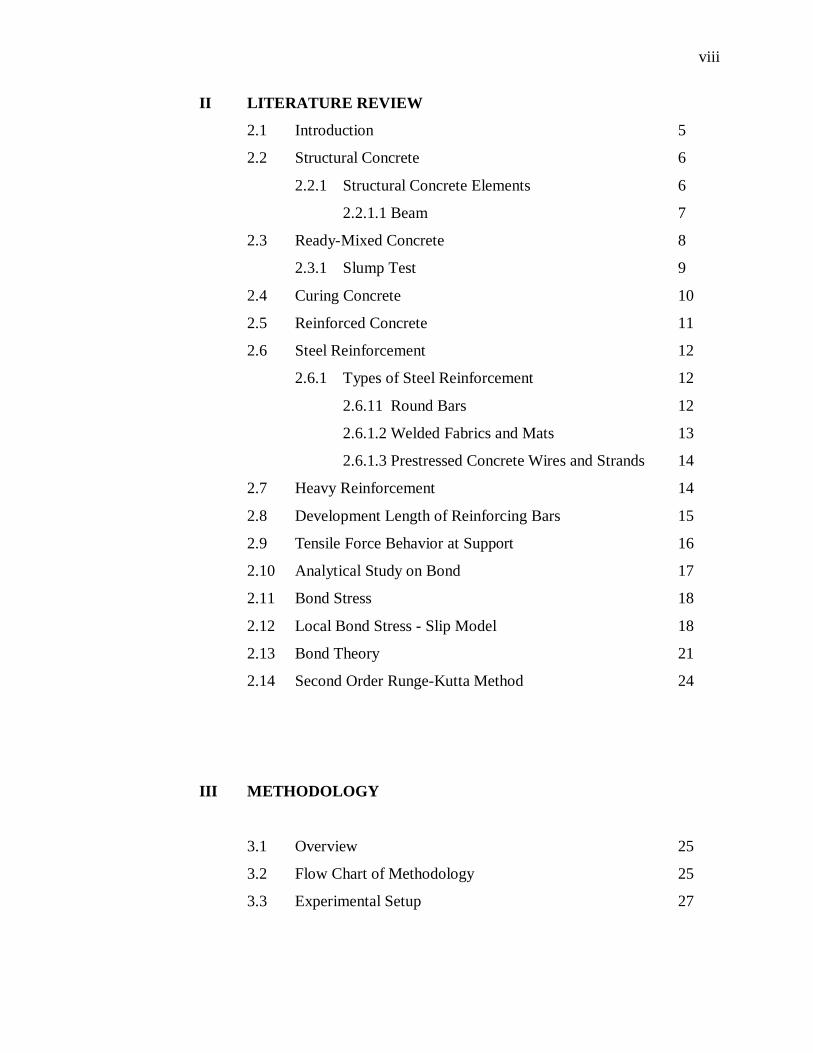
II LITERATURE REVIEW
2.1 Introduction 5
2.2 Structural Concrete 6
2.2.1 Structural Concrete Elements 6
2.2.1.1 Beam 7
2.3 Ready-Mixed Concrete 8
2.3.1 Slump Test 9
2.4 Curing Concrete 10
2.5 Reinforced Concrete 11
2.6 Steel Reinforcement 12
2.6.1 Types of Steel Reinforcement 12
2.6.11 Round Bars 12
2.6.1.2 Welded Fabrics and Mats 13
2.6.1.3 Prestressed Concrete Wires and Strands 14
2.7 Heavy Reinforcement 14
2.8 Development Length of Reinforcing Bars 15
2.9 Tensile Force Behavior at Support 16
2.10 Analytical Study on Bond 17
2.11 Bond Stress 18
2.12 Local Bond Stress - Slip Model 18
2.13 Bond Theory 21
2.14 Second Order Runge-Kutta Method 24
III METHODOLOGY
3.1 Overview 25
3.2 Flow Chart of Methodology 25
3.3 Experimental Setup 27
ix
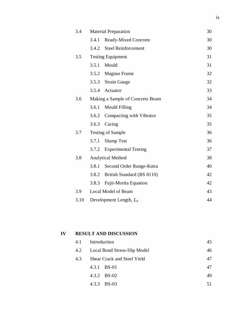
3.4 Material Preparation 30
3.4.1 Ready-Mixed Concrete 30
3.4.2 Steel Reinforcement 30
3.5 Testing Equipment 31
3.5.1 Mould 31
3.5.2 Magnus Frame 32
3.5.3 Strain Gauge 32
3.5.4 Actuator 33
3.6 Making a Sample of Concrete Beam 34
3.6.1 Mould Filling 34
3.6.2 Compacting with Vibrator 35
3.6.3 Curing 35
3.7 Testing of Sample 36
3.7.1 Slump Test 36
3.7.2 Experimental Testing 37
3.8 Analytical Method 38
3.8.1 Second Order Runge-Kutta 40
3.8.2 British Standard (BS 8110) 42
3.8.3 Fujii-Morita Equation 42
3.9 Local Model of Beam 43
3.10 Development Length, Ld 44
IV RESULT AND DISCUSSION
4.1 Introduction 45
4.2 Local Bond Stress-Slip Model 46
4.3 Shear Crack and Steel Yield 47
4.3.1 BS-01 47
4.3.2 BS-02 49
4.3.3 BS-03 51
x
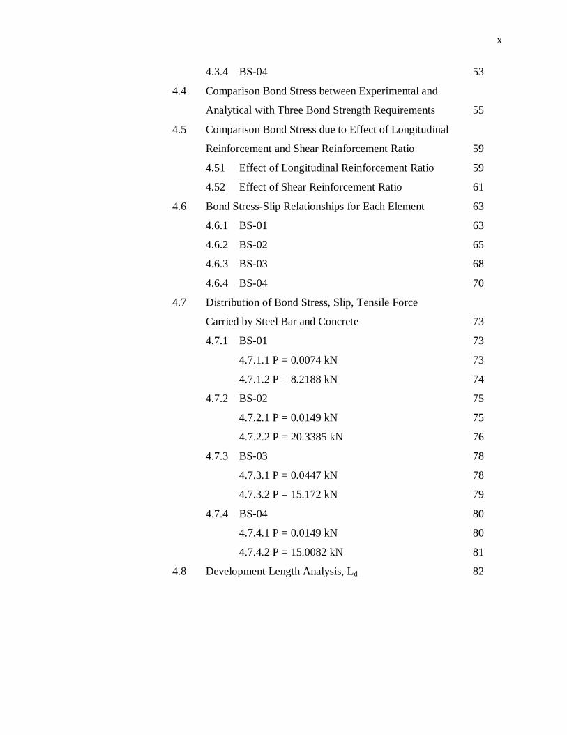
4.3.4 BS-04 53
4.4 Comparison Bond Stress between Experimental and
Analytical with Three Bond Strength Requirements 55
4.5 Comparison Bond Stress due to Effect of Longitudinal
Reinforcement and Shear Reinforcement Ratio 59
4.51 Effect of Longitudinal Reinforcement Ratio 59
4.52 Effect of Shear Reinforcement Ratio 61
4.6 Bond Stress-Slip Relationships for Each Element 63
4.6.1 BS-01 63
4.6.2 BS-02 65
4.6.3 BS-03 68
4.6.4 BS-04 70
4.7 Distribution of Bond Stress, Slip, Tensile Force
Carried by Steel Bar and Concrete 73
4.7.1 BS-01 73
4.7.1.1 P = 0.0074 kN 73
4.7.1.2 P = 8.2188 kN 74
4.7.2 BS-02 75
4.7.2.1 P = 0.0149 kN 75
4.7.2.2 P = 20.3385 kN 76
4.7.3 BS-03 78
4.7.3.1 P = 0.0447 kN 78
4.7.3.2 P = 15.172 kN 79
4.7.4 BS-04 80
4.7.4.1 P = 0.0149 kN 80
4.7.4.2 P = 15.0082 kN 81
4.8 Development Length Analysis, Ld 82
xi
V CONCLUSION AND RECOMMENDATION
5.1 Conclusion 84
5.2 Recommendation 86
REFERENCES 87
APPENDIX A 90
APPENDIX B 91
xii
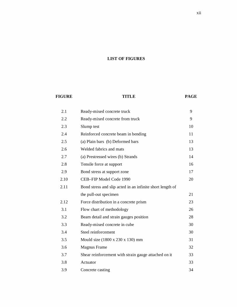
LIST OF FIGURES
FIGURE
TITLE PAGE
2.1 Ready-mixed concrete truck 9
2.2 Ready-mixed concrete from truck 9
2.3
2.4
2.5
2.6
2.7
2.8
2.9
2.10
2.11
2.12
3.1
3.2
3.3
3.4
3.5
3.6
3.7
3.8
3.9
Slump test
Reinforced concrete beam in bending
(a) Plain bars (b) Deformed bars
Welded fabrics and mats
(a) Prestressed wires (b) Strands
Tensile force at support
Bond stress at support zone
CEB–FIP Model Code 1990
Bond stress and slip acted in an infinite short length of
the pull-out specimen
Force distribution in a concrete prism
Flow chart of methodology
Beam detail and strain gauges position
Ready-mixed concrete in cube
Steel reinforcement
Mould size (1800 x 230 x 130) mm
Magnus Frame
Shear reinforcement with strain gauge attached on it
Actuator
Concrete casting
10
11
13
13
14
16
17
20
21
23
26
28
30
30
31
32
33
33
34

xiii
3.10
3.11
3.12
3.13
3.14
3.15
4.1
4.2
4.3
4.4
4.5
4.6
4.7
4.8
4.9
4.10
4.11
4.12
4.13
4.14
4.15
4.16
4.17
4.18
4.19
4.20
4.21
4.22
4.23
4.24
Compacting with vibrator
Tip concrete into slump cone
Taking reading for slump test
Experimental testing on concrete beam
Prism dimension and the distribution of bond stress,
slip, tensile force carried by the bars and concrete
Local model of beam
Local bond stress-slip model
Before testing (BS-01)
After testing (BS-01)
Shear force versus deflection for BS-01
Tensile force at support versus shear force for BS-01
Before testing (BS-02)
After testing (BS-02)
Shear force versus deflection for BS-02
Tensile force at support versus shear force for BS-02
Before testing (BS-03)
After testing (BS-03)
Shear force versus deflection for BS-03
Tensile force at support versus shear force
for BS-03
Before testing (BS-03)
After testing (BS-03)
Shear force versus deflection for BS-04
Tensile force at support versus shear force
for BS-04
Shear force versus bond stress for BS-01
Shear force versus bond stress for BS-02
Shear force versus bond stress for BS-03
Shear force versus bond stress for BS-04
Shear force versus bond stress for BS-01 and BS-03
Shear force versus bond stress for BS-02 and BS-04
Shear force versus bond stress for BS-01 and BS-02
35
37
37
37
39
43
46
47
47
47
48
49
49
49
50
51
51
51
52
53
53
53
54
55
56
57
58
59
60
61

xiv
4.25
4.26
4.27
4.28
4.29
4.30
4.31
4.32
4.33
4.34
4.35
4.36
4.37
4.38
4.39
4.40
4.41
4.42
4.43
4.44
4.45
4.46
4.47
4.48
4.49
4.50
4.51
4.52
4.53
4.54
4.55
4.56
4.57
Shear force versus bond stress for BS-03 and BS-04
Bond stress versus slip for each element (BS-01)
Bond stress versus slip for each element (BS-02)
Bond stress versus slip for each element (BS-03)
Bond stress versus slip for each element (BS-04)
Bond stress versus distance (P = 0.0074 kN)
Slip versus distance (P = 0.0074 kN)
Steel tensile force versus distance (P = 0.0074 kN)
Concrete tensile force versus distance (P = 0.0074 kN)
Bond stress versus distance (P = 8.2188 kN)
Slip versus distance (P = 8.2188 kN)
Steel tensile force versus distance (P = 8.2188 kN)
Concrete tensile force versus distance (P = 8.2188 kN)
Bond stress versus distance (P = 0.0149 kN)
Slip versus distance (P = 0.0149 kN)
Steel tensile force versus distance (P = 0.0149 kN)
Concrete tensile force versus distance (P = 0.0149 kN)
Bond stress versus distance (P = 20.3385 kN)
Slip versus distance (P = 20.3385 kN)
Steel tensile force versus distance (P = 20.3385 kN)
Concrete tensile force versus distance (P =20.3385kN)
Bond stress versus distance (P = 0.0447 kN)
Slip versus distance (P = 0.0447 kN)
Steel tensile force versus distance (P = 0.0447 kN)
Concrete tensile force versus distance (P = 0.0447 kN)
Bond stress versus distance (P = 15.172 kN)
Slip versus distance (P = 15.172 kN)
Steel tensile force versus distance (P = 15.172 kN)
Concrete tensile force versus distance (P = 15.172 kN)
Bond stress versus distance (P = 0.0149 kN)
Slip versus distance (P = 0.0149 kN)
Steel tensile force versus distance (P = 0.0149 kN)
Concrete tensile force versus distance (P = 0.0149 kN)
62
64
67
69
72
73
73
73
73
74
74
74
74
75
75
76
76
76
76
77
77
78
78
78
78
79
79
79
79
80
80
80
80
xv
4.58
4.59
4.60
4.61
Bond stress versus distance (P = 15.0082 kN)
Slip versus distance (P = 15.0082 kN)
Steel tensile force versus distance (P = 15.0082 kN)
Concrete tensile force versus distance (P=15.0082 kN)
81
81
81
81

xviii
LIST OF ABBREVIATIONS
ASTM - American Society of Testing and Materials
ACI - American Concrete Institution
BS - British Standard
CEB-FIP - Comité Euro-international du Beton-Federation internationale

xvii
LIST OF APPENDIXS
APPENDIX
TITLE PAGE
A Local Bond Stress - Slip Model 90
B Bond Stress - Slip Calculation 91
xvi
LIST OF TABLES
TABLE NO.
TITLE PAGE
3.1 Properties of beam specimens 29
4.1
Development length analysis, Ld for each beam 82
CHAPTER I
INTRODUCTION
1.1 Background of Study
Concrete is a construction material composed of cement (commonly Portland
cement) as a binder and aggregate as filler together with water and chemical admixtures.
Reinforced concrete generally known as the concrete contains reinforcement bar and it is
used throughout the world to build infrastructures and buildings, not only in the
industrialized parts of the world, but also, increasingly, throughout the developing
countries. Its advantages greatly outweigh any disadvantages. These include the fact
that the tensile strength of concrete is low compared with its compressive strength;
consequently its resistance to cracking is low. The history of the structural use of
concrete is distinguished by the efforts made to remedy this weakness, in the first place
by the addition of reinforcement made of steel or other materials (like glass fibers), and
later by prestressing.
Beam is one of the important structural parts in any building. It is used to
transfer load from roof and column to the foundation. There are many types of beam
that widely used in construction such as concrete beam and steel beam. The feature that
distinguishes each type of beams is the types of material used and its reinforcement.
Each type of beam has its own advantages and disadvantages. For example, a concrete
beam is good in compressive strength but low in tensile strength. To overcome this
2
problem, steel reinforcement added in concrete beam which steel is good in tensile
strength but low in compressive strength.
Nowadays, the concrete beams with steel reinforcement still have the market in
construction industry although there are many alternative materials used as the
reinforcement such as Glass Fiber Reinforced Polymer (GFRP). It is because the good
ability and its criteria are well known among industrial people. The study of concrete
beams heavily reinforced need to carry out to improve the ability and effectiveness of
building structure.
Concrete beams have its own properties such as compressive strength and tensile
strength. This study is just concentrates on tensile force. The tests were carried out to
the four concrete beam samples which have different in ratio of shear link and
longitudinal reinforcement. Finally a comparison had been made to examine the effect
of longitudinal reinforcement ratio on bond stress- slip behavior.
1.2 Objectives of Study
The objectives of this study are:-
i. to determine the tensile force behavior of longitudinal reinforcement of
concrete beams with heavy reinforcement.
ii. to observe bond stresses behavior occurred between the bar and concrete
along the longitudinal reinforcement at the support region due to the
effect of longitudinal reinforcement and shear reinforcement ratio.
3
1.3 Problem Statement
The applications of concrete beams with heavy reinforcement are sometimes
necessary in construction industry. The use of heavy reinforcement can avoids the
occurrence of yielding and cracking in concrete beams, besides that, it may reduce the
excessive of deflection. So the behavior of tensile force of longitudinal reinforcement of
concrete beams with heavy reinforcement and the bond stress between bar and concrete
along the longitudinal reinforcement at the support region are need to identify.
Therefore, the experimental and analytical studies are needed to carry out.
1.4 Scope of Study
The study concentrates in laboratory testing and analytical study. For the
laboratory testing, there are four concrete beams prepared and these samples were cast
for 28 days. The beam specimens were simply supported with two point load with the
dimension 130 mm wide, 230 mm deep and 1800 mm long. The diameter of
longitudinal reinforcement used are 10 mm and have a yield strength, fy = 540 MPa.
While the shear reinforcement provided by 8 mm stirrups and the yield strength, fyv =
700 MPa. Strain gauges mounted at three positions i.e. midpoint of the beam, midpoint
of the shear span and at support.
The analytical study was carrying out to determine the bond stress-slip curve at
the support zone with a computer program. This program developed using one of the
numerical methods which is Second Order Runge-Kutta method.
4
1.5 Importance of Study
The importance of this study is to identify the tensile force behavior of
longitudinal reinforcement in heavily reinforced concrete beams. This type of beam is a
regular use in any construction nowadays. The outcome from this study is it can
minimize or avoid the use of other expensive and lightweight material such as fiber
reinforced polymer (FRP) to replace steel reinforcement. Due to this outcome, it may
give a few advantages such as lower the cost of construction project.
1.6 Review of Report
The literature review of this study is included in Chapter 2. The material used
and the method applied is briefly explain in this chapter to give better understanding.
Chapter 3 is about the methodology, the procedure of testing been carried out and
analytical method involved in this study. In this chapter, all the materials and equipment
are listed and been recognized all its function to ensure the fluencies of this study. After
all testing of beam samples finished, the result obtained recorded and discuss in chapter
4. The result present in graph view. All results then discussed. Chapter 5 is the
conclusion and recommendation. From all experimental and analytical study
accomplished, the conclusion been made whether the objective of this study is achieved
or not. Then, the recommendation proposed to improve the study for the future.
CHAPTER II
LITERATURE REVIEW
2.1 Introduction
Concrete is one of the most widely used construction materials in the world
nowadays. Roughly, concrete is made by mixing small pieces of natural stone (called
aggregate) together with a mortar of sand, water, portland cement and possibly other
cementitious materials such as fly ash. One of the concrete’s advantages is that it is
readily moulded into virtually any required shape. Due to this criteria, concrete become
the preferred construction material for a wide range of buildings, bridges and other civil
engineering structures.
Generally, in civil engineering there are many important elements such as
column, beam, floor and more. Each of these elements has their respective functions in
a building or any structure. In this project, the beam elements were chosen because
these elements are very important and can have a big impact on a building or structure.
All the matters involved in this project will be described in detail his theory in
this chapter as following.
6
2.2 Structural Concrete
The term structural concrete indicates all types of concrete used in structural
applications. It may be plain, reinforced, prestressed, or partially prestressed concrete.
Structural concrete is one of the materials commonly used to design all types of
buildings. It involves two components materials which are concrete and steel. These
two materials work together to form structural members that can resist many types of
loadings (Nadim Hassoun M., 2002).
In addition concrete is used in composite design. Composite design is used for
any structural member, such as beams or columns, when the member contains a
combination of concrete and steel shapes.
Generally, the design of different structures is achieved by performing two main
steps which are:-
i. Determining the different forces acting on the structures using proper
methods of structural analysis
ii. Proportioning all structural members economically, considering the
safety, serviceability, stability, and functionality of the structure.
2.2.1 Structural Concrete Elements
Structural concrete can be used for almost all buildings, whether single story or
multistory. The concrete building may contain some or all of the following main
structural elements (Nadim Hassoun M., 2002).
i. Slabs are horizontal plate elements in building floors and roofs. They
may carry gravity loads as well as lateral loads. The depth of slab is
usually very small relative to its length or width.
7
ii. Beams are long horizontal or inclined members with limited width and
depth. Their main function is to support loads from slabs.
iii. Columns are members that support loads from beams or slabs. They may
be subjected to axial loads or axial loads and moments.
iv. Frames are structural members that consist of a combination of beams
and columns or slabs, beams and columns. They may be statically
determinate or statically indeterminate frames.
v. Footings are pads or strips that support columns and spread their loads
directly to the soil.
vi. Walls are vertical plate elements resisting gravity as well as lateral loads
as in the case of basement walls.
2.2.1.1 Beam
The structural element used in this project is beam. Generally beams carry
vertical gravitational forces but can also be used to carry horizontal loads (i.e., loads due
to an earthquake or wind). The loads carried by a beam are transferred to column, walls,
or girders, which then transfer the force to adjacent structural compression members.
Beams are characterized by their profile (the shape of their cross-section), their length,
and their material. In contemporary construction, beams are typically made of steel,
reinforced concrete, or wood.
Internally, beams experience compressive, tensile and shear stresses as a result of
the loads applied to them. Typically, under gravity loads, the original length of the beam
is slightly reduced to enclose a smaller radius arc at the top of the beam, resulting in
compression, while the same original beam length at the bottom of the beam is slightly
stretched to enclose a larger radius arc, and so is under tension. The same original
length of the middle of the beam, generally halfway between the top and bottom, is the
same as the radial arc of bending, and so it is under neither compression nor tension, and
defines the neutral axis. Above the supports, the beam is exposed to shear stress. There
are some reinforced concrete beams in which the concrete is entirely in compression
8
with tensile forces taken by steel tendons. These beams are known as prestressed
concrete beams, and are fabricated to produce a compression more than the expected
tension under loading conditions. High strength steel tendons are stretched while the
beam is cast over them. Then, when the concrete has cured, the tendons are slowly
released and the beam is immediately under eccentric axial loads. This eccentric loading
creates an internal moment, and, in turn, increases the moment carrying capacity of the
beam. They are commonly used on highway bridges.
2.3 Ready-Mixed Concrete
Ready-mixed concrete is a processed material which in a plastic and unhardened
state, is sold as a finished product ready for use. Its quality depends on the ingredients,
their proportions, and the thoroughness with which they are combined. Ready-mixed
concrete will not remain in the plastic and unhardened state beyond a limited time, the
exact period of which depends upon circumstances. Responsibility for the final quality
of concrete produced as ready-mixed concrete is divided. The producer delivers it to the
user who places it in the work and gives it whatever subsequent treatment it receives.
Therefore, all tests which measure the acceptability of fresh concrete at the point where
the responsibility for its handling passes from the producer to the user are of special
significance. Furthermore, all tests, of any kind, of concrete as a material become of a
particular importance because of the nature of the contractual relations involved (ASTM,
1956).
Concrete’s natural color is gray and its favored uses are utilitarian. It is very
ubiquity causes it to blend into the background. But ready-mix concrete does have one
remarkable characteristic: other than manufactured ice, perhaps no other manufacturing
industry faces greater transport barriers. The transportation involved is the truck as
shown in Figure 2.1. The transportation problem arises because ready-mix concrete both
has a low value-to-weight ratio and is highly perishable. It absolutely must be
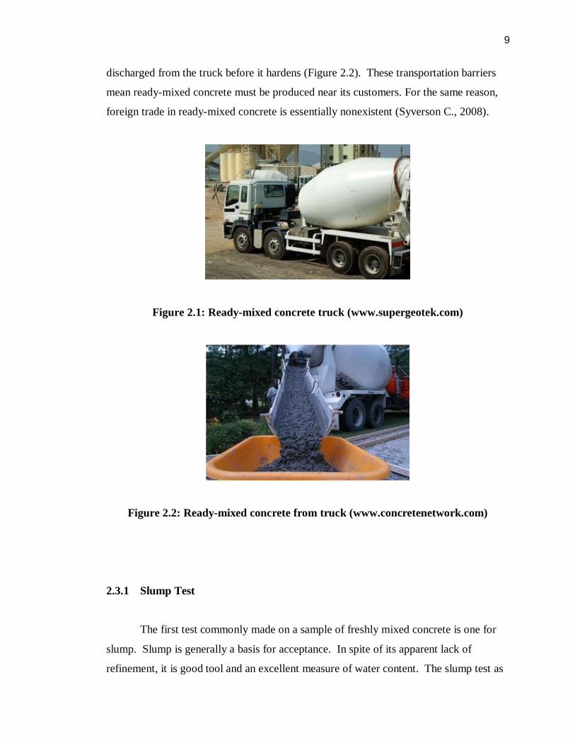
9
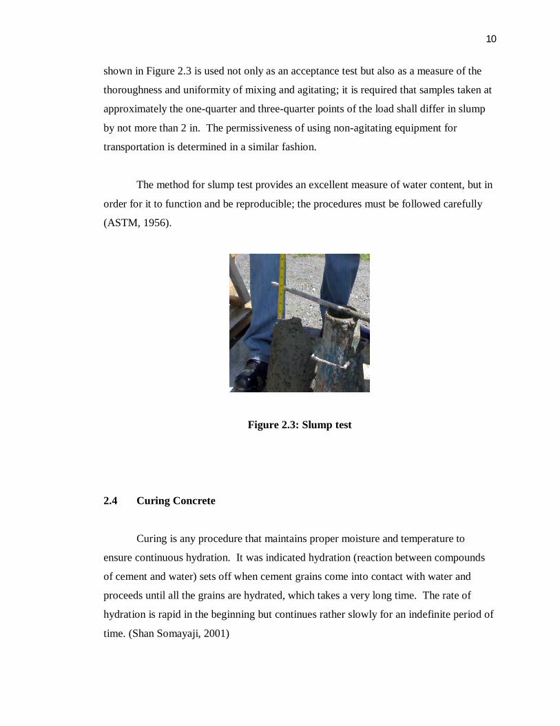
discharged from the truck before it hardens (Figure 2.2). These transportation barriers
mean ready-mixed concrete must be produced near its customers. For the same reason,
foreign trade in ready-mixed concrete is essentially nonexistent (Syverson C., 2008).
Figure 2.1: Ready-mixed concrete truck (www.supergeotek.com)
Figure 2.2: Ready-mixed concrete from truck (www.concretenetwork.com)
2.3.1 Slump Test
The first test commonly made on a sample of freshly mixed concrete is one for
slump. Slump is generally a basis for acceptance. In spite of its apparent lack of
refinement, it is good tool and an excellent measure of water content. The slump test as
10
shown in Figure 2.3 is used not only as an acceptance test but also as a measure of the
thoroughness and uniformity of mixing and agitating; it is required that samples taken at
approximately the one-quarter and three-quarter points of the load shall differ in slump
by not more than 2 in. The permissiveness of using non-agitating equipment for
transportation is determined in a similar fashion.
The method for slump test provides an excellent measure of water content, but in
order for it to function and be reproducible; the procedures must be followed carefully
(ASTM, 1956).
Figure 2.3: Slump test
2.4 Curing Concrete
Curing is any procedure that maintains proper moisture and temperature to
ensure continuous hydration. It was indicated hydration (reaction between compounds
of cement and water) sets off when cement grains come into contact with water and
proceeds until all the grains are hydrated, which takes a very long time. The rate of
hydration is rapid in the beginning but continues rather slowly for an indefinite period of
time. (Shan Somayaji, 2001)

11
2.5 Reinforced Concrete
Although concrete is widely used in construction industry, it has most serious
deficiency which is lack of tensile strength. This problem can be solved by
incorporating steel reinforcement, usually in the form of thin bars, in the regions where
tensile forces have to be carried. The concrete and steel reinforcement bond well
together and a composite structural material is achieved which can be used to construct a
wide variety of elements and structures (Warner RF, et al., 1998).
In reinforced concrete, the structural properties of the component materials are
put to efficient use. It means that the concrete carries compression and the steel
reinforcement carries tension. Figure 2.4 shows the structural action of simple
reinforced concrete beam. The load induces tension in the lower part of the beam, and
the concrete cracks. However, the steel in the cracked region carries the tensile force, so
that in the section shown in Figure 2.4 (b) the steel tensile force T and the concrete
compressive force C form a couple to resist the moment M.
Figure 2.4: Reinforced concrete beam in bending (Warner RF, et al., 1998)
12
2.6 Steel Reinforcement
Reinforcement is usually in the form of steel bars. It is placed in the concrete
member, mainly in tension zone, to resist tensile forces resulting from external load on
the member. Reinforcement is also used to increase the member’s compression
resistance. Steel costs more than concrete, but it has yield strength about 10 times the
compressive strength of concrete.
Longitudinal bars taking either tensile or compression force in a concrete
member are called main reinforcement. Additional reinforcement in slabs, in a direction
of perpendicular to the main reinforcement, is called secondary or distributed
reinforcement. In reinforced concrete beams, another type of steel reinforcement is
used, transverse to the direction of the main steel and bent in a box or U shape. These
are called stirrups. Similar reinforcements are used in columns, where they are called
ties (Nadim Hassoun M., 2002).
2.6.1 Types of Steel Reinforcement
Nadim Hassoun M., (2002) stated there are different types of steel reinforcement
are used in various reinforced concrete members. These types can be classified as
follows:-
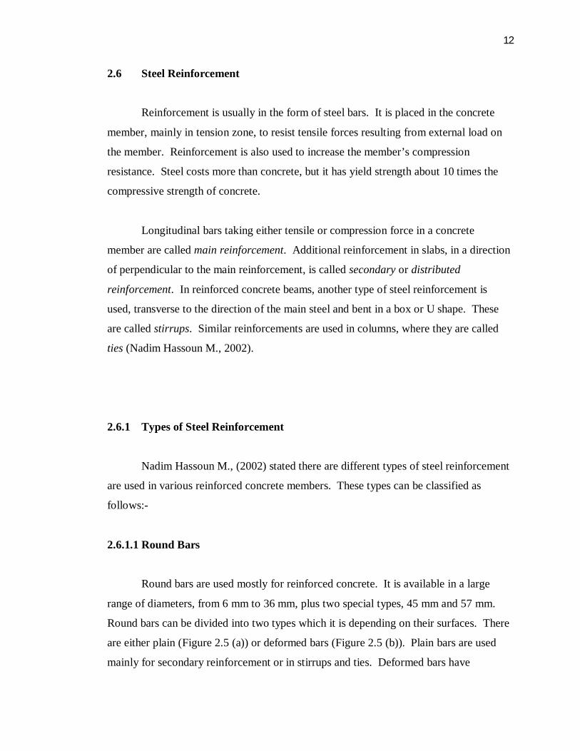
2.6.1.1 Round Bars
Round bars are used mostly for reinforced concrete. It is available in a large
range of diameters, from 6 mm to 36 mm, plus two special types, 45 mm and 57 mm.
Round bars can be divided into two types which it is depending on their surfaces. There
are either plain (Figure 2.5 (a)) or deformed bars (Figure 2.5 (b)). Plain bars are used
mainly for secondary reinforcement or in stirrups and ties. Deformed bars have
13
projections or deformations on the surface. It is to improve the bond with concrete and
reducing the width of cracks opening in the tension zone.
(a) Plain bars
(www.stainlesssteelpipeflange.net)
(b) Deformed bars (www.traderscity.com)
Figure 2.5: Round bars
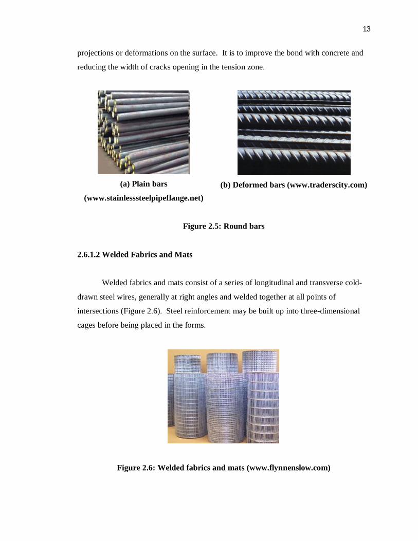
2.6.1.2 Welded Fabrics and Mats
Welded fabrics and mats consist of a series of longitudinal and transverse cold-
drawn steel wires, generally at right angles and welded together at all points of
intersections (Figure 2.6). Steel reinforcement may be built up into three-dimensional
cages before being placed in the forms.
Figure 2.6: Welded fabrics and mats (www.flynnenslow.com)
14
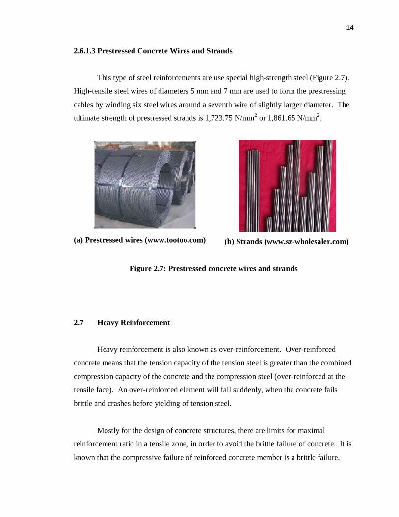
2.6.1.3 Prestressed Concrete Wires and Strands
This type of steel reinforcements are use special high-strength steel (Figure 2.7).
High-tensile steel wires of diameters 5 mm and 7 mm are used to form the prestressing
cables by winding six steel wires around a seventh wire of slightly larger diameter. The
ultimate strength of prestressed strands is 1,723.75 N/mm2 or 1,861.65 N/mm2.
(a) Prestressed wires (www.tootoo.com)
(b) Strands (www.sz-wholesaler.com)
Figure 2.7: Prestressed concrete wires and strands
2.7 Heavy Reinforcement
Heavy reinforcement is also known as over-reinforcement. Over-reinforced
concrete means that the tension capacity of the tension steel is greater than the combined
compression capacity of the concrete and the compression steel (over-reinforced at the
tensile face). An over-reinforced element will fail suddenly, when the concrete fails
brittle and crashes before yielding of tension steel.
Mostly for the design of concrete structures, there are limits for maximal
reinforcement ratio in a tensile zone, in order to avoid the brittle failure of concrete. It is
known that the compressive failure of reinforced concrete member is a brittle failure,
15
even if the concrete of normal strength (more ductile than the high strength concrete) is
used. In the compression failure of reinforced concrete beams, concrete crushes before
steel yields. This type of beam is said to be over-reinforced. Concrete of over
reinforced beam reaches ultimate stress, but steel does not reach the yield strain (Ivana
Kesegić et. al., 2009). The over-reinforced concrete beam has reinforcement ratio of 3%
(Belgin C. M. and Sener S., 2007).
In context of cost, an over-reinforced section is always uneconomical because of
the increase in the moment resistance is not proportion to the increase in the area of
tensile reinforcement. Furthermore, the concrete having reached maximum allowable
stress cannot take more additional load without adding compression steel (Punmia B.C.,
Ashok Kumar Jain, et al, 1992).
2.8 Development Length of Reinforcing Bars
The joint behavior of steel and concrete in a reinforced concrete member is based
on the fact that a bond is maintained between the two materials after the concrete is
hardened. If a straight bar of round section is embedded in concrete, a certain force is
required to pull the bar out of the concrete. If the embedded length of bar is long
enough, the steel bar may yield and it will leave some length of the bar in the concrete.
The bonding force depends on the friction between steel and concrete. It is influenced
mainly by the roughness of the steel surface area, shrinkage, the concrete mix, and the
concrete cover. Deformed bars give a better bond than plain bars. Rich mixes have
greater adhesion than weak mixes. Ultimate bond stress of a steel bar can be improved
by the increasing in the concrete cover (Nadim Hassoun M., 2002).
Generally, the bond strength is influenced by the following factors:-
i. Yield strength of reinforcing bars, fy. Longer development length is
needed with higher fy.
16
ii. Quality of concrete and its compressive strength, f’c. The increasing of f’c
reduces the required development length of reinforcing bars.
iii. Bar size, location and spacing in concrete section. Horizontal bars placed
with more than 304.8 mm of concrete below them have lower bond
strength due to the fact that concrete shrinks and settles during the
hardening process. Wide spacing of bars also can improve the bond
strength. It gives an adequate effective concrete area around each bar.
iv. Concrete cover to reinforcing bars. A small cover may cause the cracking
and spalling of the concrete cover.
v. Confinement of bars by lateral ties. Adequate confinement by ties or
stirrups prevents the spalling of concrete around bars.
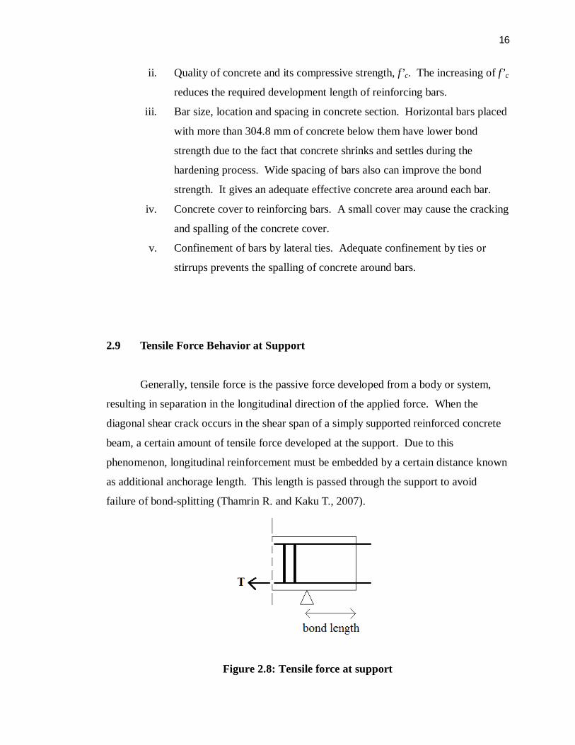
2.9 Tensile Force Behavior at Support
Generally, tensile force is the passive force developed from a body or system,
resulting in separation in the longitudinal direction of the applied force. When the
diagonal shear crack occurs in the shear span of a simply supported reinforced concrete
beam, a certain amount of tensile force developed at the support. Due to this
phenomenon, longitudinal reinforcement must be embedded by a certain distance known
as additional anchorage length. This length is passed through the support to avoid
failure of bond-splitting (Thamrin R. and Kaku T., 2007).
Figure 2.8: Tensile force at support
17
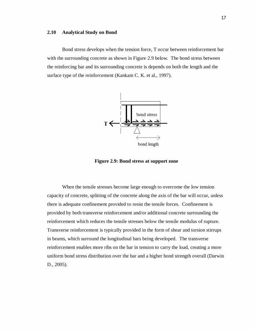
2.10 Analytical Study on Bond
Bond stress develops when the tension force, T occur between reinforcement bar
with the surrounding concrete as shown in Figure 2.9 below. The bond stress between
the reinforcing bar and its surrounding concrete is depends on both the length and the
surface type of the reinforcement (Kankam C. K. et al., 1997).
Figure 2.9: Bond stress at support zone
When the tensile stresses become large enough to overcome the low tension
capacity of concrete, splitting of the concrete along the axis of the bar will occur, unless
there is adequate confinement provided to resist the tensile forces. Confinement is
provided by both transverse reinforcement and/or additional concrete surrounding the
reinforcement which reduces the tensile stresses below the tensile modulus of rupture.
Transverse reinforcement is typically provided in the form of shear and torsion stirrups
in beams, which surround the longitudinal bars being developed. The transverse
reinforcement enables more ribs on the bar in tension to carry the load, creating a more
uniform bond stress distribution over the bar and a higher bond strength overall (Darwin
D., 2005).

18
2.11 Bond Stress
In reinforced concrete, a good bond between the reinforcement and the concrete
is required for an optimal interaction of these two materials. Without this property,
reinforced concrete is not thinkable in its present-day applications. A reinforcement bar
bonds to the surrounding concrete by means of the bond stress (τd). This is so much the
more important as the roughness of the bar increases. It is known that the bond stress
depends on the quality of the concrete, the way the concrete was poured (parallel or
perpendicular to the axis of the reinforcement), and the position of the bar in the
concrete (upper- or under-reinforcement) and the cover and the diameter of the bar
(Vandewalle L. and Mortelmans F., 1988).
Furthermore, the selection of a proper type of specimen for bond strength
evaluation is of great importance as it significantly influences the bond characteristics.
The selection of a proper specimen is still a matter of controversy and until now no test
specimen has been devised which fully represents the actual bond behavior. In
reinforced concrete beams or slabs, the concrete surrounding the tensile reinforcement is
in tension, whereas the concrete in this test is in compression, which not only eliminates
tension cracks in the specimen but also increases the bond strength. Moreover, during
the test, a small load causes a slip and the peak bond stress moves in front of the slip
(Abdullah A. Almusallam et. al., 1995).
2.12 Local Bond Stress - Slip Model
Bond plays a significant role in reinforced concrete elements response and its
mechanical behavior system. The phenomenon has the duty to transfer the stresses form
the reinforcement bars to surrounding concrete.

19
“Perfect bond” can be used for first stages of analysis when perfect compatibility
for concrete and reinforcement nodes` displacement can be assumed. After this stage, as
the load is increasing, inevitably bond-slip takes place due to the occurrence of cracks.
This affects the stress transfer between reinforcement and concrete. Due to this reason,
different displacements are observed in the steel and, on the other hand, in the concrete.
At the cracks, local strain of the bar is many times higher than the average strain (strain
localization).
Bond-slip occurs for two principal causes which are slip due to damage in
concrete adjacent to bars exhibited by cracking and crushing, and slip on the interface
between steel bar and surrounding concrete. The mechanism manifests in two different
ways: tension stiffening, and an increase of flexibility at member ends, due to bar pull-
out at the interface node connection. These effects are extremely noticeable under
hysteretic loads when bond is lost and high strains and damages occur. The connection
between reinforcement bar and concrete is considered perpendicular. When a bar is
pulled out, besides the tangential stresses parallel with the bar direction, radial stresses
normal to the bar direction are generated. The interaction between these two kinds of
stresses appear either directly, due to the shear stresses from the concrete element in
areas close to reinforcement or indirectly, due to higher bond stresses caused by larger
ribs (CEB-FIP 1990).
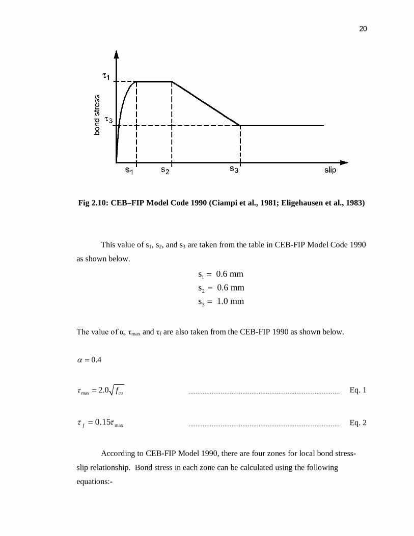
Figure 2.10 below shows the CEB-FIP Model 1990 which is the graph between
bond stress versus slip. τ1 is corresponding to s1 and τ3 is corresponding to s3.
20
Fig 2.10: CEB–FIP Model Code 1990 (Ciampi et al., 1981; Eligehausen et al., 1983)
This value of s1, s2, and s3 are taken from the table in CEB-FIP Model Code 1990
as shown below.
1
2
3
s 0.6 mms 0.6 mms 1.0 mm
The value of α, τmax and τf are also taken from the CEB-FIP 1990 as shown below.
0.4
max 2.0 cuf ………………………………………………………………………… Eq. 1
max0.15f ………………………………………………………………………… Eq. 2
According to CEB-FIP Model 1990, there are four zones for local bond stress-
slip relationship. Bond stress in each zone can be calculated using the following
equations:-
21
max
max
max max
/ 1 for 0 1 for 1 2
2 for 2 3 3 2
f
f
S S S SS S S
S S S S SS S
for 3 S S
............................. Eq. 2 (a)
............................. Eq. 2 (b) ............................. Eq. 2 (c) ............................. Eq. 2 (d)
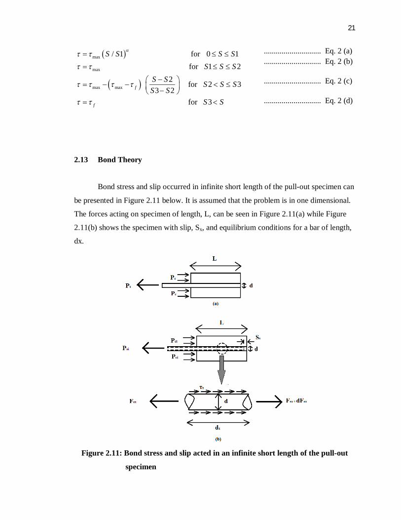
2.13 Bond Theory
Bond stress and slip occurred in infinite short length of the pull-out specimen can
be presented in Figure 2.11 below. It is assumed that the problem is in one dimensional.
The forces acting on specimen of length, L, can be seen in Figure 2.11(a) while Figure
2.11(b) shows the specimen with slip, Sx, and equilibrium conditions for a bar of length,
dx.
Figure 2.11: Bond stress and slip acted in an infinite short length of the pull-out
specimen

22
The slip, Sx, at a distance x along the reinforcement bar is defined as the relative
displacement between the bar and the concrete, that is:
x sx cxS u u ……………………...… Eq. 3 (a)
or
0 0
x x
x sx cxS dx dx …….………......……… Eq. 3 (b)
where:- usx = displacement of the bar at point x
ucx = displacement of the concrete at point x
εs = bar strains
εc = concrete strains
By differentiating Eq. 3, the increase of the local slip ds within an infinitesimal bar
length dx at the location x can be determined.
xs c
dSdx
……………………….… Eq. 4
The strains in the bar and concrete at each section along the prism can be written as:
sxsx
s s
FE A
, cxcx
c c
FE A
…………………………. Eq. 5
we have; x sx cx
s s c c
dS F Fdx E A E A
………………………. Eq. 6
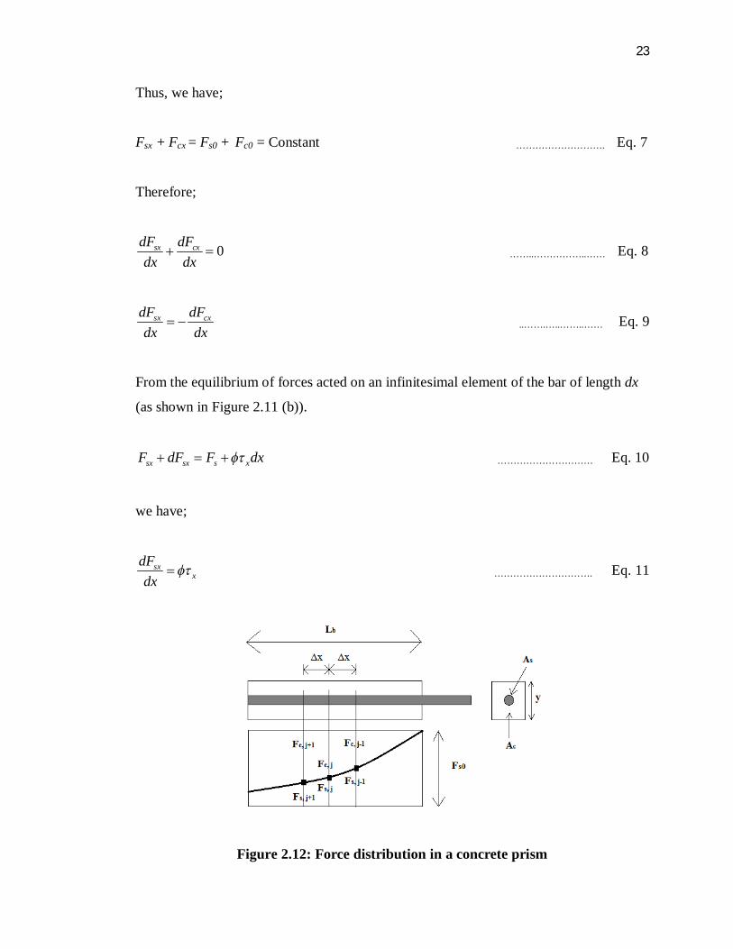
The total force at each cross section along the concrete prism is always constant as can
be seen in Figure 2.12. It is determined by using the general equilibrium of forces.
23
Thus, we have;
Fsx + Fcx = Fs0 + Fc0 = Constant ………………………. Eq. 7
Therefore;
0sx cxdF dFdx dx
……..……………..…… Eq. 8
sx cxdF dFdx dx
..…….…..……..…… Eq. 9
From the equilibrium of forces acted on an infinitesimal element of the bar of length dx
(as shown in Figure 2.11 (b)).
sx sx s xF dF F dx ………………………… Eq. 10
we have;
sxx
dFdx
…………………………. Eq. 11
Figure 2.12: Force distribution in a concrete prism

24
The general second order differential equation for bond slip is found as follows by
substituting Eq. 11 into Eq. 6 and differentiating with respect to x:-
2
2
(1 )x
s s
d S ndx E A
……………………………… Eq. 12
where s
c
EnE
and s
c
AA
2.14 Second Order Runge-Kutta Method
In order to solve second order differential equation of bond stress-slip
relationship (Eq. 12), Second Order Runga-Kutta was applied in this study. Only first
order ordinary differential equations can be solved by using the Runge-Kutta second
order method. The Second Order Runge-Kutta method is a numerical technique used to
solve an ordinary differential equation of the form:-
00,, yyyxfdxdy
REFERENCES
Abdullah A. Almusallam et. al. (1995). “Effect of Reinforcement Corrosion on Bond
Strength.” Saudi Arabia.
American Society for Testing and Materials (1956). “Significance of Tests and
Properties of Concrete and Concrete Aggregates.”
British Standard 8110 (BS 8110: Part 1: 1985). “Clause 3.12.8.4: Values for Design
Ultimate Anchorage Bond Stress.” United Kingdom.
Belgin C. M. and Sener S. (2007). “Size Effect on Failure of Over-Reinforced
Concrete Beams.” Turkey.
Comité Euro-international du Beton-Federation internationale. (1990). “CEB-FIP
Model Code for Concrete Structures.” London.
Darwin, D. (2005). “Tension Development Length and Lap Splice Design for
Reinforced Concrete Members.” USA.
Flynn & Enslow The Total Screening Source. “Welded fabric.”
http://www.flynnenslow.com
Ivana Kesegić et. al., (2009). “Deflection of Over-Reinforced Concrete Beams:
Comparison of Analytical, Numerical and Experimental Results.” Hrvatska.

88
Kankam C. K. et al., (1997). “Relationship of Bond Stress, Steel Stress, and Slip in
Reinforced Concrete.” Ghana.
Morita S. and Fujii S. (1982). “Bond Capacity of Deformed Bars due to Splitting of
Surrounding Concrete.” Japan.
Nadim Hassoun M. (2002). “Structural Concrete, Theory and Design.”
Second Edition, New Jersey.
Punmia B.C., Ashok Kumar Jain, et al (1992). “Reinforced Concrete Structures,
Volume 1.” New Delhi.
Shan Somayaji (2001). “Civil Engineering Materials.” New Jersey.
Star Tubes & Fittings. “Round Bar.” http://www.stainlesssteelpipeflange.net
SuperGeo GIS Software & Solution. “Ready Mixed Concrete Truck Dispatch
Management System.” http://www.supergeotek.com
Syverson C. (2008). “Markets: Ready-Mixed Concrete.” Chicago.
Sz-wholesaler. “Prestressed Concrete Strands.” http://www.sz-wholesaler.com
Thamrin R. and Kaku T. (2007). “Bond Behavior of CFRP Bars in Simply Supported
Reinforced Concrete Beam with Hanging Region.” Japan.
The Concrete Network. “Research Decorative Concrete.”
http://www.concretenetwork.com
Tootoo. “Wholesale Pc Wire Strand.” http://www.tootoo.com
89
TradersCity. “Deformed Bar.” http://www.traderscity.com
Vandewalle L., Mortelmans F. (1988). “The Bond Stress between a Reinforcement
Bar and Concrete: Is It Theoretically Predictable?” Belgium.
Warner RF., Rangan BV., Hall AS. & Faulkes KA. (1998). “Concrete Structures.”
Australia.


![Politeknik Sultan Salahuddin Abdul Aziz Shahrepository.psa.edu.my/bitstream/123456789/1290/1/JKA... · 2019. 2. 13. · Terangkan tegasan ricih dan terikan ricih. [5 marks] [5 markah]](https://img.dokumen.tips/doc/110x75/60e54fe8c740e64ad156be34/politeknik-sultan-salahuddin-abdul-aziz-2019-2-13-terangkan-tegasan-ricih-dan.jpg)