Embed Size (px)
Citation preview

TENNESSEE VALLEY AUTHORITYCHATTANOOGA. TENNESSEE 37401
1400 Chestnut Street Tower II
May 2, 198'4
Director of Nuclear Reactor RegulationAttention: Ms. E. Adensam, Chief
Licensing Branch No. 14Division of Licensing
U.S. Nuclear Regulatory CommissionWashington, D.C. 20555
Dear Ms. Adensam:
In the Matter of the Application of ) Docket Nos. 50-390Tennessee Valley Authority)
Westinghouse (W) has developed and applied improved analytical techniquesin the reanalysis of the Watts Bar Nuclear Plant (WBN) steamline breaktransients which allow for the BoroniInjection Tank (BIT) to be bypassed,eliminated, or reduced in concentration and the heat tracing systemdeleted. The enclosed W generated study, "Report for the BIT ConcentrationReduction/BIT Elimination Study for Watts Bar Units 1 and 2,"1 (Enclosure 1)provides a detailed description of the criteria and methodology used in thereanalysis and presents the analytical results.
In consideration of the current unit 1 fuel load schedule (June 19814) andthe extensive design/hardware modifications required for a completeelimination of the BIT and associated subsystems, TVA, for WBN unit 1, haselected to implement the alternative to reduce the boron concentration inthe BIT to below four percent by weight which will in turn eliminate theneed for heat tracing. Consequently, the corresponding technical specifi-cations can be deleted. In order to ensure that this issue is resolved ina timeframe consistent with the "proof and review" phase of the unit 1Technical Specifications,'we are forwarding approved FSAR chapter 6,"Engineered Safety Features," and chapter 15, "Accident Analysis," changes(Enclosure 2). These revisions will be reflected in future amendments tothe WBN FSAR. Also enclosed are proposed unit 1 Technical Specificationschanges (Enclosure 3).
Several FSAR chapter 6 changes resulting from the BIT concentrationreduction issue will not be submitted until the resolution of thecontainment temperature concerns (steam generator tube uncovery/superheatissue), which will ultimately require chapter 6 revisions. It is TVA'sopinion however, that the BIT concentration reduction issue is indepen-dent of the superheat issue and therefore resolution of the former shouldproceed at the earliest date possible. (Please note that resolution of thesuperheat issue will include any contributing effects from the BIT concen-tration reduction modifications.)
8405070054 840502PDR ADOCK 0500039-0-.A PDR
1983-TVA 50TH ANNIVERSARYAn Equal Opportunity Employer I

Director of' Nuclear Reactor Regulation May 2, 19841
Additional evaluations will be performed for unit 2 to determine the mostbeneficial course of action.
If you have any questions concerning this matter, please get in touch withD. B. Ellis at FTS 858-2681.
Very truly yours,
TENNESSEE VALLEY AUTHORITY
L. M.M:ý illsŽ MagrNuclear Licensing
Sworn Nond subscribed before methis ___day of 198J4a
Notary PublicMy Commission Expiresq C W
Enclosures (3)cc: U.S. Nuclear Regulatory Commission (Enclosures)
Region IIAttn: Mr. James P. O'Reilly Administrator101 Marietta Street, NW, Suite 2900Atlanta, Georgia 30303

ENCLOSURE 1
* WATTS BAR NUCLEAR PLANT
WESTINGHOUSE GENERATED REPORT FOR THE BIT CONCENTRATIONREDUCTION/BIT ELIMINATION STUDY

WBNP
The upper head injection accumulators are located outside con-tainment. Protection is also provided against the release of.accumulator gas by accumulator pressure indicators and alarms.These enable the operator to take action promptly as required tomaintain plant operation within the requirements of the technical4specifications covering accumulator operability.
A complete listing of design parameters for the upper head in-jection accumulators is presented in Table 6.3-1.
Uyler Head Iniection Surae Tank
The design parameters for the upper head injection surge tank aregiven in Table 6.3-1. The tank is designed to accomodate chang~esin the volume of- the injection water stored in the accumulatordue to normal temperature changes and t6o allow for some leakageinto the UHI accumulator during normal plant operation. Twoindependent channels provide level indication in the control roomand actuate a common alarm should the level approach the limit ofthe operating band.
PUMPS__________________________________
Residual Heat Removal Pumps
Residual heat removal pumps are provided to deliver water fromthe refueling water storage tank or the containment sump to theReactor Cool~ant System should the Reactor Coolant System pressurefall below their shutoff head. Each residual heat removal
6.3-5

WBNP
'pump is a single stage, vertical position, centrifugal pump. ithas an integral motor--pump shaft, driven by an induction motor.The unit has a self contained mechanical seal cooling system.Component cooling water is the heat exchange medium. The pumpsare interlocked to start on receipt of the safety injectionsignal.
A minimum flow bypass line is provided for the pumps to recir-culate through the residual heat exchangers and return the cooledfluid to the pump suction should these pumps be started withtheir normal flow paths blocked. Once flow i s established to theReactor Coolant System, the bypass line is automatically closed.This line prevents deadheading the pumps and permit~s pump testingduring normal operation.
The residual heat removal pumps are also discussed in Section5.5.7.
Centrifugal Charging Pumps
These pumps deliver water from the refueling water storage tankthrough the boron injection tank to the Reactor Coolant System. atthe prevailing Reactor Coolant System pressure. Each centrifugalcharging pump Is a multistage, diffuser design, barrel typecasing with vertical sucti-on and discharge nozzles. The pump isdriven through a speed increaser connected to an induction motor.The unit has a self contained lubrication system, and mechanicalseal cooling system. Component cooling water is the normal hea~tlexchange medium for the mechanical seal. The pumps areinterlocked to start on receipt of the safety injection signal.
A minimum flow bypass line is provided on each pump discharge to.recirculate flow to the volume control tank after cooling in theseal water heat exchanger, if required, to protect the pumps atthe shutoff head. The charging pumps may be tested during normaloperation through the use of the minimum flow bypass line. Thecentrifugal charging pumps are also discussed in Section 9.3.4.
Safety Iniection Pumps
The safety injection pumps deliver water from the refueling waterstorage tank after the Reactor Coolant System pressure Is reducedbelow their shutoff head. Each high head safety inject~ion pumpis a multistage, centrifugal pump. The pump is driven directlyby an induction motor. The unit has a self
6.3-6

WB NP
A separate motor driven gag is provided on each isolation valveto manually lock the valve in the closed position during plantoperations at low pressure. The gag is manually removed and thevalve then moved to the open position following plant startup.
Butterfly Valves
Each main residual heat removal line has an air-operated.butterfly valve which is- normally open and is designed to fail inthe open position. These valves are left in the full openposition during normal operation to maximize flow from thissystem to the Reactor Coolant System during the injection model ofthe Emergency Core Cooling System operation.
Pivinit
All-piping joints are welded except for the pump and butterflyvalve flanged connections.
Weld connections for pipes sized 2-1/2 inches and larger are buttwelded. Reducing tees are used where the branch size exceedsone-half of the header size. Branch connections of sizes thatare equal to or less than one-half of the header size conform tothe ANSI code. Branch connections 1/2 inch through 2 inches areattached to the header by means of full penetration welds, usingpre-engineered integrally reinforced branch connections.
Mnimum piping and fitting wall thicknesses as determined by ANSIB31.1.0-1967 Ed. formula are increased to account for themanufacturer's permissible tolerance of minus,12-1/2 percent onthe nominal wall and an appropriate allowance for wall thinning,.on the external radius during any pipe bending operations in theshop fabrication of the subassemblies.
6.3-11

WBNP
System Oneration
The operation of the Emergency Core Cooling System, following aloss-of-coolant accident, can be divided into two distinct moddt:
1. The injection mode in which any reactivity increase followingthe postulated accidents is terminated, initial cooling ofthe core is accomplished, and coolant lost from the primarysystem in the case of a loss-of-coolant accident isreplenished, and
2. The recirculation mode in which long term core cooling isprovided during the accident recovery period.
A discussion of these modes follows.
Break Spectrum Coverage
The principal mechanical components of the Emergency Core CoolingSystem which provide core cooling immediately following a loss-of-coolant accident are the accumulators, the safety injectionpumps, the centrifugal charging pumps, the residual heat remov-al;pumps, refueling water storage tank, and the associated valves,ý,and piping.
For large pipe ruptures, the Reactor Coolant System would bedepressurized and voided of coolant rapidly, and a high flow rateof emergency coolant is required to quickly cover the exposed fuelrods and limit possible core damage. This high flow is initiallyprovided by the upper head accumulators discharging into thereactor vessel head followed by the passive cold leg accumulators,the charging pumps, safety injection pumps, and the residual heatremoval pumps discharging into the cold legs of the Reactor.Coolant System. The residual heat removal and safety injectionpumps deliver into the accumulator injection lines, between thetwo check valves, during the injection .mode. The charging pumpsdeliver coolant to the cold legs during the injection mode.
Em ergency cooling is provided for small ruptures primarily by thehigh need' injection pumps and upper head accumulators. Small
'The charging pumps and safety injection pumps are commonlyreferred to as 'high head pumps' and the residual heat removalpumps as 'low head pumps.' Likewise, the term 'high headinjection' is used to denote charging pump and safety injectionpump injection and 'low head injection' refrs to residual heatremoval pum Injection.
6.3-12

WBNP
ruptures are those, with an equivalent diameter of 6 inches orless, which do not immediately depressurize the Reactor CoolantSystem below the accumulator discharge pressure. The centrifugalcharging pumps are designed to deliver borated water at theprevailing Reactor Coolant System. During the injection mode,the charging pumps will take suction from the refueling waterstorage tank.
The safety injection pumps also take suction from the refuelingwater storage tank and deliver borated water to the cold legs ofthe Reactor Coolant System. The safety injecition pumps begin todel~iver water to the Reactor Coolant System After the pressure.has fallen below the pump shutoff he~ad.
Core protection is afforded with the minimum engineered safety'feature equipment.' The minimum engineered safety featureequipment is defined by consideration of the single failurecriteria as discussed in Sections 6.3.1.4 and 3.1. The minimumdesign case will ensure the entire break spectrum is accountedfor, and core cooling design bases of Section.6.3.1 are met. Theanalyses for this case are presented in Sections 15.3 and 15.4..
For large Reactor Coolant System ruptures, the accumulators andthe active high head and low head pumping components serve tocomplete the core refill. One residual heat removal pump isrequired for long term recirculation.
If the break is small (6 inch equivalent diameter or less) theaccumulators with one charging pump and one safety injection pumpensure adequate cooling during the injection mo~de. Long termrecirculation requires one residual heat removal pump andcomponents of the auxiliary heat removal systems which arerequired to transfer heat from the Emergency Core Cooling System(e.g., Component Cooling System and Essential Raw Cooling WaterSystem). The loss of coolant analyses are presented in Section15-.3 and 15.4.
Certain modifications (i.e., reduced component availability) tothe normal operating status as given in Table 6.3-4 of theEmergency Core Cooling System are permissible without impairingthe ability of the Emergency Core Co oling System to provideadequate core cooling capability. Accordingly, TechnicalSpecifications have been established (see Chapter 16) to coverthese modifications.
The Technical Specifications permit one cold leg accumulator tobe isolated for check valve leakage testing. They also permitvarious pumps of the Emergency Core Cooling System to beinoperable during power operation and for an additional timeperiod while the reactor is at hot shutdown, provided that the
6 .3-13

WBNP
1. S~tarts the diesel generators and, if all other sources of.power are lost, aligns them to the 6.9-ky shutdown boards.
2. Starts the charging pumps, the safety injection pumps, andthe residual heat removal pumps.
3. Aligns the charging pumps for injection by:
a. Closing the valves in the charging pump discharge line tothe normal charging line.
b. Opening the valves in the charging pumps suction linefrom the refueling water storage tank.
C. Closing the valves in the charging pump normal suctionli~ne from the volume control'tank.
d. Opening the boron injection tank inlet and discharge lineisolation valves.
Remotely operated valves for the injection mode which are undermanual cont~rol (i.e., valves which normally are in their readyposition and do not require a safety injection signal) have theirpositions indicated on a common portion of the control board. ifa component is out of its prope~r position, its monitor light willindicate this on the control panel. At any 'time during operationwhen one of these valve is not in the ready position forinjection, this condition is shown visually on the board, and anaudible alarm is sounded in the control room.
The injection mode. continues until the low level is reached inthe refueling water storage tank avid the recirculation mode isinitiated.
Rec irculat ion Mode-
The-injection mode continues until the RHR pumps have beenrealigned to the recirculation mode. During the injection modeall pumps take suction from the refueling water storage tank(RWST) until a low level signal from the RWST in conjunction withthe 'a'.signal and a high sump level signal aligns the residualheat removal pumps to take suction from the containment sump.The RHR block valves (FCV-7.4-3 and 21) are'automatically closedcoincident with the opening of the sump isolation valves (FCV-63-72 and 73.). The automatic positioning of these valves isinitiated only in the event that actuation signals are generatedby the safeguards protection logic (Is' signal), two of four RWSTlow level protection logic signals, and two out of four sump highlevel signals'. It has been determined that the RHR pumps
6.3-16

WBNP
6.3.3.3 Alternate Analysis Methods
Small Pipe Break
The small pipe break analysis is used to evaluate the initialcore thermal transient for a spectrum of pipe rupture from 3/8inch up to and including the rupture of a six inch diameter pipe.For breaks 3/8 inch or smaller, the charging system can maintainthe pressurizer level at the Reactor Coo~lant System operatingpressure and the Emergency Core Cooling System wou.ld not beactuated.
The results of the small pipe break analysis indicate that th-elimits on core behavior are adequately met, as shown in Section15.3.
Main Steam System Sinale Active Failure
Analyses of reactor behavior following any single active failurein the main steam system which results in an uncontrolled releaseof steam are included in Section 15.2. The analyses assume thata single valve (largest of the safety, relief, or bypass valves)opens and fails to close, which results in an uncontrolledcooldown of the Reactor Coolant System.
Results indicate that if the incident is initiated at the hotshutdown condition, which results in the worst reactivity tran-sient, there is no return to criticality. Thus, the EmergencyCore Cooling System provides adequate protection for this inci-dent .
St-eam Line Rupture
Following a steam line rupture the Emergency Core Cooling Systemis automatically actuated to deliver borated water from the boroninjection tank to the Reactor Coolant System. The response ofthe Emergency Core Cooling System following a steam line break isidentical to its response during the injection mode of operationfollowing a loss-of-coolant accident.
This accident is discussed in detail in Section 15.4. Thelimiting steam line rupture is a complete line severance.
In the case of a steam line rupture when offsite power is notassumed lost, credit is taken for the uninterrupted availabilityof power for the Emergency Core Coolant System components.
The results of the analysis in Section 15 .4 indicate that thedesign basis criteria are met. Thus, the Emergency Core CoolingSystem adequately fulfills its shutdown reactivity addition
function.
6 .3-33

WB NP
The safety injection actuation signal initiates identical act~ionsas described for the injection mode of the loss-of- coolantaccident, even though not all of these actions are requiredfollowing a steam line rupture, e.g., the residual heat removalpumps are not required since the Reactor Coolant System pressurewill remain above their shutoff head.
The delivery of the concentrated boric acid from the chargingpump results in a negative reactivity change to counteract the
increase in reactivity caused by the system cooldown.* TheIcharging pumps continue to deliver borated water from therefueling water storage tank, until enough water has been addedto the Reactor Coolant System to make up for the shrinkage due tocooldown. The safety injection pumps also delive *r berated waterfrom the refueling water storage tank for the interval when theReactor.Coolant System pressure is less than the shutoff head ofthe safety injection pumps. After pressurizer water level hasbeen restored, the operator will verify that the criteria for'Safety Injection Termination' as defined in the EmergencyOperating Instructions are satisfied before manually terminatinginjection flow.
The sequence of events following a postulated steam line break isdescribed in Section 15.4.
6.3.3.4 Fuel Rod-Perforations
Discussions of peak clad temperature an d metal-water reactionsappear in Sections 15.3.1 and 15.4.1. Analyses of the radio-logical consequences of RCS pipe ruptures also are presented inSection 15.4.1.
6.3.3.5 Evaluation Model
Does not apply to this pl ant (BWRs only).
6.3.3.6 Fuel Clad Effects
Does not apply to this plant (BWRs only).
6.3.3.7 ECCS Performance
6.3-34
WBNP
Does not apply to this plant (BWRs only).
6.3 .3 .8 Peak-Factors
Does not apply to this plant (BWRs only).
6.3.3.9 Fuel Rod Perforations,
Does not apply to this plant (BWRs only).
6.3.3.10 Conformance with Interim Acceptance Criteria
Does not apply to this plant (BWRs only).
6.3.3.11 Effects of ECCS Operation on the Core
The effects of the ECCS on the reactor core are discussed in,Sections 15.3 and 15.4.
6.3.3.12 Use of Dual Function-Components
The Emergency Core Cooling System contains components which haveno other operating function as well as components which areshared with other systems and perform normal operating functions.ýComponents in each category are as follows:
1. Components of the Emergency Core Cooling System which performno other functions are:
a. Two upper head injection accumulators which dischargeborated water into the upper head of the reactor vessel.
b. One accumulator for each loop which discharges boratedwater into its respective cold leg of the reactor coolantloop piping.
C. Two safety injection pumps which supply borated water forcore cooling to the Reactor Coolant System.
d. Associated piping, valves and instrumentation.
2. Component s which also have a normal operating function are asfollows:
a. The residual heat removal pumps and the residual heatexchangers: These components are normally used duringthe latter stages of normal reactor cooldown and when the.reactor is held at cold shutdown for core decay heatremoval.. However, during aill other plant operating
6.3-35
A1
WBNP
6.3.5 Instrumentation Application
instrumentation and associated analog and logic channels employedfor initiation of Emergency Core Cooling System operation isdiscussed in Section 7.3. This section describes theinstrumentation employed for monitoring Emergency Core CoolingSystem components during normal plant operation and also Emer-gency Core Cooling System post ac''cident operation. All alarmsare annunciated in the control room.
6.3.5.1. Temperature Indication
Residual Heat Exchanger Inlet Temperature
The fluid temperature at the inlet and outlet of each residualheat exchanger is recorded in the control room.
Refuelina Water Storage Tank (RWST) Temperature
Two temperature channels are provided to monitor the RWST tem-perature. Both are indicated in the Main Control Room.
6.3.5.2 Pressure Indication
Boron I1niection-Tank Pressure
Boron injection tank pressure is indicated in the control room.A high pressure alarm is provided.
Safety Iniection Reader Pressure
Safety injection pump discharge header pressure is indicated inthe control room.
Cold Leg Accumulator Pressure
Duplicate pressure channels are installed on each cold leg
6.3-41
WB NP
accumulator. Pressure indication in the control room and highand low pressure alarms are provided by each channel.,
TJHI Isolation Valve Hydraulic Accumulator Pressure
The hydraulic pres sure of each of the four hydraulic accumulatorsis monitored independently with pressure readout and a lowpressure alarm light on the hydraulic service panel in the con-trol room and annunciation on the main control board.
Test Line Pressure
A local pressure indicator used to check for proper seating ofthe accumulator check valves between the injection lines and theReactor Coolant System is installed on the leakage test line.
Residual Heat Removal-Pump Discharge Pressure
Residual heat removal discharge pressur-e for each pump is indi-cated in the control room. A high pressure alarm is actuated byeach channel.
Upper Head I njection Accumulator Pressure
Duplicate pressure channels are installed on the upper headinjection surge tank. Pressure indication, for this accumulatorsystem, is provided in the control room, together with high andlow pressure alarms, by each channel.
Alarms are also provided that the operator will manually closeand gag the hydraulic isolation valve during plant shutdown atpressure below 1900 psi and manually release the gag and open the'valve at pressures in excess of 1900 psi during plant startup.
6.3.5.3 Flow Indication
Charsing Pump Iniection Flow
Injection flow to the reactor cold legs injector is indicated -inthe control room.
Residual Heat Removal-Pump, Injection Flow
Flow through ea~ch residual heat removal injection and recircu-lation header leading to the reactor cold or hot legs isindicated in the control room.
6.3-42
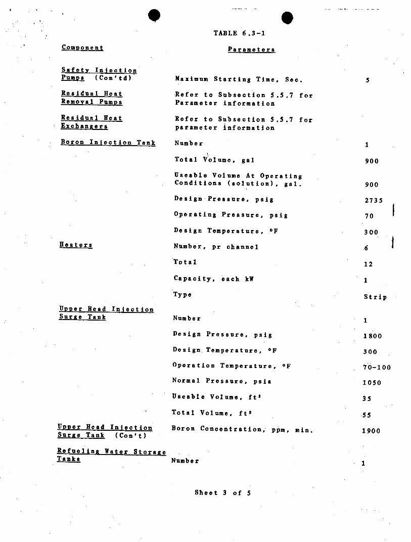
0TABLE 6.3-1
Component Parameters
Safety IniectionPumps (Con'td)
Residual HeatRemoval Pumps
Residual HeatExchangers
Boron Injection Tank
Heaters
Upper Head InjectionSurste Tank
Upper Head IniectionSurge Tank (Con't)
Refueling Water StorageTanks
Maximum Starting Time, Sec.
Refer to Subsection 5.5.7 forParameter informati on
Refer to Subsection 5.5.7 forparameter informa tion
Number
Total Volume, gal
Useable Volume At Operating
Conditions (solution), gal.
Design Pressure, psig
Operating Pressure, psig
Design Temperature, OF
Number, pr channel
Total
Capacity, each kW
Type
Number
Design Pressure, psig
Design.Temperature, OF
Operat~ion Temperature, OF
Normal Pressure, psia
Useable Volume, ft3
Total Volume, fts
Boron Concentration,- ppm, min.
Numbeor
Sheet 3 of 5
5
1
900
900
2735
70
300
6
12
1
Strip
1
1800
300
70-100
1050
35
1900

TABLE 6.3-5
EMERGENCY CORE COOLING SYSTEM SEARED FUNCTIONS EVALUATION
Component
Reful ing WaterStorage Tank
CentrifugalCharging Pumps
Residual. HeatRemoval Pumps
Residual HeatExchangers
Safety InjectionPumps
Accumulators
UHI Accumulators
Normal Operating Arrangement
Lined up to suction of safetyinjection, containment spray, andresidual heat removal pumpa,
Lined up for charging serviceSuction from volume control tanks
Lined up to cold legs of reactorcoolant piping.
Lined up for residual heat removalpump operation.
Lined up to cold legs of reactorcoolant piping
Lined up to cold legs of -reactorcoolant piping.
Lined up to upper head of reactor vessel.
Accident Arrangement
Lined up to suction of centri-fugal. charging, safety injection.reaidual heat removal pumps, andcontainment spray pumps. Valvesfor realignment meet single fai-lure criteria.
Lined up to inlet of boron injec-tion tank and outlet of RWST.Valves for realignment meet singlefailure criteria.
Lined up to 'cold legs of reactorcoolant piping.
Lined up for residual heat. removalpump operations.
Lined up to cold legs of reactorcoolant piping.
Lined up to cold legs of reactorcoolant piping.
Lined up to upper head of reactorvessel.

TABLE 15.1-2 (Continued)
SUMMARY OF INITIAL CONDITIONS AND COMPUTER CODES USED
COMP UTERCODES UTILIZED
REACTIVITY COEFFICIENTSASSUMED T]
MODERATOR MODERATORTEMPERATURE DENSITY(iAk/ 0F) - C~k/gm/cc) DOPPLER
INITIAL NSSSFIERMAL _POWER OUTPUT
ASSUMED*
(MWt)
CONDITION II (Cont'd)
Excessive Heat Removal Due to MARVELFeedwater System Malfunctions (2)
Excessive Load Increase Incident LOFTRAN
Accidental Depressurization of LOFTRANthe Reactor Coolant System
Accidental Depressurization of LOFTRANthe Main Steam System
0. 43 .lower (1)
Figure 15.1-7. lowerand 0.143
O~~and 3)425
(1)
Figure 15.1-7 upper (1l)
Function of.ModeratorDensity SeeSection 15.2.13(Figure 15.2-140)
31425
31425
0I(subcritical)
Inadvertent Operation of ECCSDuring Power Operation
L OFTRAN Minimum (2) lower (1)
CONDITION III
Loss of Reactor Coolant fromSmall Ruptured Pipes or fromCracks in Large Pipes whichActuates Emergency Core Cooling
WFLASH, LOCTA-IV
3579
,(Sheet 2 of 4)
FAULTS
31425

TABLE 15.1-2 (Continued)
SUMMARY OF INITIAL CONDITIONS AND COMPUTER CODES USED
FAULTS
CONDITION IV (Cont'd)
Major secondary system piperupture up to and includingdouble ended rupture(Rupture of a Steam Pipe)
Steam Generator Tube Rupture
Single Reactor Coolant Pump
Locked Rotor
Fuel Handling Accident
Rupture of a Control RodMechanism Housing(RCCA Ejection)
CODES UTILIZED
LOFTRAN, THINC
PHOENIX,ý LOFTRANTHINC, FACTRAN
NA
TWINKLE, FACTRANLEO0 ARD
REACTIVITY COEFFICIENTSASSUMED TH1
MODERATOR MODERATORTEMPERATURE DENSITY(Ak/0 F) - (Ak/gm/cc) DOPPLER
Function ofModeratorDensity SeeSection 15.2.13(Figure 15.2-140)
INITIAL NSSSERMAL POWER OUTPUT
AS SUMED *
(MVWt)
0(Subcritical)
3579
Figure 15.1-7 lower (1) 2397 and31425
3579
Refer toSection15.14.6
Consistent 0 and 31425with lowerlimit shownon Figure 15.1-5
Notes:0
(1) Reference Figure 15.1-5(2) Reference Figure 15.1-7(3) Reference Figure 15.14-9
* .. A minimum of 2 percent margin has to be applied
(Sheet 4 of 4)

A
WBNP
RCS pressure will stabilize following operator action toterminate flow to the inadvertantly opened valve; normaloperating procedures may then be followed. the 'operatingprocedures would call for operator action to control RCS boronconcentration and pressurizer level using the CVCS and tomaintain steam generator level through control of the main orauxiliary feedwater system. Any action required of the operatorto stabilize the plant will be in a time frame in excess of tenminutes following reactor trip.
15.2.12.3 Conclusions
The pressurizer low pressure and the overtemperature ppT ReactorProtection System signals provide adequate protection againstthis9 accident, and the minimum DNBR remains in excess of 1.30.
15.2.13 ACCIDENTAL DEPRESSURIZATION OF THE MAIN STEAM SYSTEM
15.2.13.1 Identification of Causes and Accident Description
The most severe core conditions resulting from an accidentaldepressurization of the Main Steam System' are associated with aninadvertent opening of a single steam dump, relief of safetyvalve. The analyses performed assuming a rupture of a main steamline are given in Section 15.4.2.1.
The steam release as a consequence of this accident results in aninitial increase in steam flow which decreases during theaccident as the steam pressure falls. The energy removal fromthe Reactor Coolant System causes a reduction of coolanttemperature and pressure. In the presence of a negativemoderator temperature coefficient, the cooldown results in-a,reduction of core shutdown margin.
The analysis is performed to demonstrate that the followingcriterion is satisfied: Assuming a stuck rod cluster controlassembly, with or without offsite power, and assuming a singlefailure in the Engineered Safety Features there will be noconsequent fuel damage after reactor trip for a steam releaseequivalent to the spurious opening, with failure to close, of thelargest of any single steam dump, relief or safety valve. Thiscriterion is satisfied by verifying the DNB design basis is met.
The following systems provide the necessary protection against anaccidental depressurization of the main steam system.
1. Safety Injection System actuation from any of the following:
a. Two out of three signals of low-'low pressurizer pressure
b. Two out of three high containment pressure signals.
15 .2-39

ft I W
15 .2-39a
WBNP
C. Two out of four loops high steam line flow coincidentwith either two out of four loops low steam line pressureor two out of four loops low-low T.av
2. The overpower reactor trips (neutron flux and T and thereactor trip occuring in conjunction with receipt of thesafety injection signal.
3. Redundant isolation of the main feedwater lines: Sustainedhigh feedwater flow would cause additional cooldown.Therefore, in addition to the normal control action whichwill close the main feedwater valves following reactor trip,a safety injection signal will rapidly close all feedwatercontrol 'valves, trip the main feedwater pumps, and close thefeedwater pump discharge valves.
4. Trip of the fast-acting steam line stop valves (Main StreamIsolation Valves) (designed to close in less than 5 seconds)on:
a. High-high containment pressure.
b. Two out of four loops high steam line flow conincidentwith either two out of four loops low steam linepressure or two o .ut of four. loops low-low T ae

WB NP
c. Two out of three high negative steam pressure rate in anyloop (below Permissive P-1l).
15.2.13.2 Analysis of Effects and Consequences
Method of Analysis
The following analyses of a secondary system steam release areperformed for this section.
1. A full plant digital computer simulation to determine ReactorCoolant System transient conditions during cooldown, and
the effect of safety injection [5].,2. Analyses to determine that there is no consequential
fuel damage.
The following conditions are assumed to exist at the time of asecondary steam system release.
1. End-of-life shutdown margin at no load, equilibrium xenonconditions, and with the most reactive rod cluster controlassembly stuck in its fully withdrawn position. Operation ofrod cluster control assembly banks during core burnup isrestricted in such a way that addition of positive reactivityin a secondary system steam release accident will not lead toa more adverse condition than the case analyzed.
2. A negative moderator coefficient corresponding to the end-of-life rodded core with the most reactive rod cluster contro~lassembly In the fully withdrawn position. The variation ofthe coefficient with temperature and pressure is included.,The keff versus temperature at 1000 psi corresponding to-the-negative moderator temperature coefficient used is shown inFigure 15.2-40.
3. Minimum capability for injection of high concentration borica cid solution corresponding to the most restric~tive singlefailure in the Safety Injection System. This corresponds tothe flow delivered by one charging pump delivering its fullcontents to the cold leg header. The injection curve used isshown in Figure 15.4-10. Low concentration boric acid must:be swept from the safety injection lines downstream of theRWST prior to the delivery of high concentration boric acid(1950 ppm) to the reactor coolant loops. This effect hasbeen all-owed for in the analysis.
15.2-40

0 ~WBNP0
4. The case studies is a steam flow of 247 pounds per second at1100 psia from one steam generator with offsite poweravailable. This is the maximum capacity of any single steamdump, relief or safety valve. Initial hot shutdownconditions at time zero are assumed since this represents themost conservative initial condition.
Should the reactor be just critical or operating at power atpower at the time of a steam release, the reactor will betripped by the normal overpower protection when power levelreaches a trip point. Following a trip at power, the ReactorCoolant System contains more stored energy than at no load,the average coolant temperature is higher than at no load andthere is appreciable energy stored in the fuel.
Thus, the additional stored energy is removed via thecooldown caused by the steam release before the no loadconditions of Reactor Coolant System temperature and shutdownmargin assumed in the analyses are reached. After theadditional stored energy has been removed, the cooldown andreactivity insertions proceed in the same manner as in theanalysis which assumes no load condition at time zero.However, since the initial steam generator water inventory. isgreatest at no load, the magnitude and duration of t heReactor Coolant System cooldown are greater for steam linerelease occuring from no load conditions.
5. In computing the steam flow, the Moody Curve for fl/D 0 is,used.
6. Perfeot moisture separation in the steam generator isasasaumned.
Results
The results presented are a conservative indication of the eventswhich would occur assuming a secondary system steam release sinceit-is postulated that all of the conditions described above occursimultaneously.
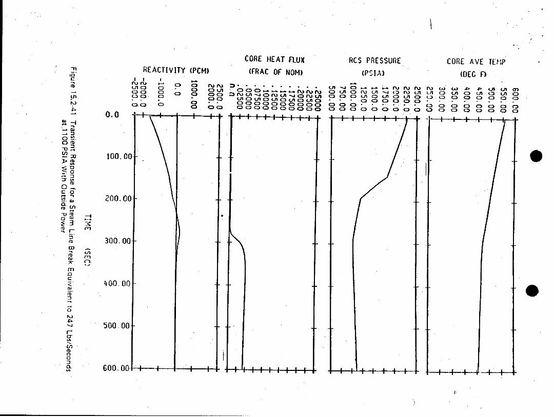
Figure 15.2-41 shows the transients arising as the result of asteam flow of 247 lbs/second total at .1100 psia with steamrelease from four steam generators. The assumed steam release istypical of the capacity of any single steam dump relief or safetyvalve. In this case safety injection is-initiated automaticallyby low pressurizer pressure. Operation of one centrifugalcharging pump is considered. Boron solution at 1950 ppm entersýthe Reactor Coolant System providing sufficient negativereactivity to, assure no fuel damage.
15 .2-41

WBS
The cooldown for the case shown in Figure 15.2-41 is mo re rapidthan the case of steam release from all steam generators throughone steam dump, relief, or safety valve. The transient isconservative with respect to cooldown, since no credit is takenfor the energy stored in the system metal other than that of thefuel elements.
Following blowdown of the faulted steam gene rator, the plant canbe brought to a stabilized hot standby condition through controlof auxiliary feedwater flow and safety injection flow, asde scribed by plant operating procedures. The operatingprocedures would call for operator action to limit RCS pressureand pressurizer level by terminating safety injection flow, andto control steam generator level and RCS coolant temperatureusing the auxiliary feedwater system. Any action required of theoperator to m aintain the plant in a stabilized condition will be.in a time frame in excess of ten minutes following safetyi nj eot ion actuation.
15.2.13.3 Conclusions
The analysis shows that the criteria stated earlier in thissection are satisfi ed since a DNBR less than 1.30 does not exist.
15.2.14 INADVERTENT OPERATION OF EMERGENCY CORE COOLING SYSTEM
.This analysis was performed before the boron injection tank andassociated 900 gal. of 20,000 ppm boron was deleted from theWatts Bar design basis, and therefore it is still referencedthrough this section. This analysis is however still limiting,since the boron injection tank and associated 900 gal. of 20,000ppm boron lead to a more conservative result.
15.2.14.1 Identification of Causes and Accident Description
Spurious Emergency-Core Cooling System (ECCS) operation at powercould be caused by operator error or a false electrical actuatingsignal. Spurious actuation may be assumed to be cause'd by any ofthe following:
1. High containment pressure
2. Low pressurizer pressure
3., Low steam line pressure and low steam generator level
4. Manual actuation
Following the actuation signal, the suction of the centrifugalcharging pumps is diverted from the volume control tank to therefueling water storage tank. The valves isolating the boroninjection tank from the charging pumps and the valves isolating
.15.2-42

WBNP
the boron injection tank from the injection header thenautomatically o pen. The charging pumps then force highlyconcentrated (20,000 ppm) boric acid solution from the boroninjection tank, through the header and injection line and into
15 .2-42a
TABLE 15.2-1 (Continued)
TIME SEQUENCE OF EVENTS FORCONDITION II EVENTS
Event Time (sec.)
Accidental depressuriza-tio~n of the ReactorCoolant System.
Accidental depressuriza--tion of the MainSteam System
Inadvertent Operation ofECCS during powerOperation
Inadvertent opening ofone RCS safety valve
Reactor Trip
Minimum DNBR occurs
Inadvertent opening ofone main steam safetyor relief valve
Criticality attained
Pressurizer empties
UHI injection
Boron reaches core
Charging pumps begin in-jecting borated water
Low pressure trip pointreached
Rods begin to drop
Accident
17.6
19.6
232
130
192
194

1.06
ZERO POWER. 1000 PSIA105 END OF LIFE RODDEDCORE WITH ONE RCCASTUCK FULL OUT
1.0%I
S1.03
1I.02
1.01
1.00
0.99
0.98r250 300 350 .4w 500 550
CORE AVERAGE 1E34ERATURE (OF)
Figue 152-40 Vari.ation of Keff wit Core TemperatureFigure 15.2-40
REACTIVITy (pCM)
tLnc) C) o ouc3C) CD C) o LcCcm C) 00 C:3c3
C3, CD CD cD C) cD
CORE HEAT FLUX(FRAC OF NOM)
C3 C CD \3 r ruc.:) .JOC)OLA-4C3rurCA-- C lbt C3U
c)C)C3C) C: D Clca) c 3CDcc)c)c)CDCDc)CD cýDc C3 DC> c
RCS PRESSURE
(PSIA)
C) R-.- -. lC) r\) cLi -4 (-3
CDLf C) fLn c)CD c )c
Tnto
cD
>mD
.0:T &
o 0~Lph
a c
CD
-Dmnw
cD
0'I
fD
En
0
'A
I I I f I I I -
CORE AVE TEM~P
(A) C) .L
c:) C3 CIOc:)C C:)
t fl C )
C-'3C)
0.0
too.
200.
LA C)
C) C)c)CDoCD CD c~ CD C)
300.
4.00. 00
500. 00-
G00. 00 I . . . . a .

W bN ~
15.4.2 M~aor-Secondary System Pipe-Rupture
15.,4..2.1 Major Rupture off a Main Steam Line
15.4.2.1.1 -Identification of' Causes and Accident Description
The steam release arising from. a rupture off a main steam linewould result in an initial increase in steam flow which de-creases during the accident as the steam pressure falls. Theenergy removal from the Reactor Coolant System causes a reduc-.tion of coolant temperature and pressure. In the presence ofa negative moderator~ temperature coefficient, the cooldownresults In a reduction of core shutdown margin. If the mostreactive rod cluster control. assembly .(RCCA) -is assumed stuckin its fully withdrawn position after reactor trip, there isan increased possibility that the core will become critical

WBNP
and return to power. A return to power following a steam linerupture is a potential problem mainly because of the high powerpeaking factors which exist assuming the most reactive RCCA to bestuck in its fully withdrawn position. The core is ultimatelyshut down by the boric acid injection delivered by the SafetyInjection System.
The analysis of a main steam line r~upture is performed todemonstrate that the following criterion is satisfied:
Assuming a stuck RCCA with or without offsite power, and assuminga s ingle failure in the engineered safeguards the core. remains inplace and intact. Radiation doses are not expected to exceed theguidelines of lOCFRlOO.
Although DNB and possible clad perforation following a steam piperupture are not necessarily unacceptable, the following analysis,.in fact, shows that no DNB occurs for any rupture assuming themost reactive assembly stuck in its fully withdrawn position.
The following functions provide the necessary protection for asteam line rupture:
1. Safety Injection System actuation from any of the following:
a. Two out of three signals of low pressurizer pressure
b. Two out of three high containment-pressure.
C. Low steam line pressure in any one loop relative to two,out of three other loops.
d. High steamline flow in two out of four loops coincidentwith either two out of four loops low steamline pressureor two out of four loops low-low T.
2. The overpower reactor trips (neutron flux and *W*T) and thereactor trip occurring in conjunction with receipt of thesafety injection signal.
3. Redundant isolation of the main feedwater lines: Sustainedhigh feedwater flow would cause additional .cooldown.Therefore, in addition to the normal control action whichwill close the main feedwater valves, a safety injectionsignal will rapidly close all feedwater control valves, mainfeedwater isolation valves, trip the
15.4-10

WBNP-
main feedwater pumps, and close feedwater pump dischar ge
4. Trip of the fast acting steam line stop valves (main steamisolation valves) (designed to close in less than 5 seconds)on:.
a. Two out of four High-High containment pressure.
b. Two out of-four loops high steamline flow coincident witheither two out of four loops low steamline pressure ortwo out of four low-low T in the coolant loops.
.Fast-acting isolation valves are provided in each steam line thatwill fully close within 7 seconds after a steamline isolation Isignal setpoint is reached. For breaks downstream of theisolation valves, closure of all valves would completelyterminate the blowdown. For any break, in any location, no morethan one steam generator would blowdown even if one of theisolation 'valves fails to close. A description of steam lineisolation is included in Chapter 10.
Steam flow is measured by monitoring-dynamic head in nozzleslocated in the throat of the steam generator. The, effectivethroat area of the nozzle.s is 1.4 square feet, which isconsiderably less than the main steam pipe and thus the nozzlesalso serve to limit the maximum steam flow for a break at anylocation.
Table 15.4-6 lists the equipme nt required in the recovery from ahigh energy line rupture. Not all equipment is required for anyone particular break, since it will vary depending uponpostulated break location and details of initial conditions.Design criteria And methods of protection of safety relatedequipment from the dynamic effects of postulated piping rupturesare provided in Section 3.6.
.15.4.2.1.2 Analysis-of Effects And Consequences.
Method of Analysis
The analysis 'of the steam pipe rupture has been performed todetermine:
15.4-1l

WBNP
1.The core heat flux and Reactor Coolant. System temperature and.pressure resulting from the cooldown following the steam linebreak. The LOFTRAN [11] Code has been used.
2. The thermal and hydraulic behavior of the core following asteam line break. A detailed thermal and hydraulic digital-computer code, TRINC, has been used to determine if DNBoccurs for the core conditions computed in Item 1 above.
The following conditions were assumed to exist at the time of amain steam line break accident.
1. End-of-life shut down margin at no load, equilibrium xenonconditions, and the most reactive RCCA stuck in its fullywithdrawn position: Operation of the control rod banksduring core burnup is restricted in such a way that additionof positive reactivity in a steam line break accident willnot lead to a more adverse condition than the case analyzed.
2. The negative moderator coefficient corresponiding to the end-of-life rodded core with the most reactive RCCA in the fully.withdrawn position: The variation of the coefficient withtemperature and pressure has been included. The k versustemperature at 1000 psi corresponding to the negativemoderator temperature coefficient used is shown in Figure15.2-40. The effect of power generation in the core onoverall reactivity is shown in Figure 15.4-9.
The core properties associated with the sector nearest theaffected steam generator and those associated with theremaining sector were conservatively combined to obtainaverage core properties for reactivity feedback calculations.Further, it was conservatively assumed that the core powerdistribution was uniform. These two conditions causeunderprediction of the reactivity feedback in the high powerregion near the stuck rod. To verify the conservatism ofthis method, the reactivity as well as the power distributionwas checked for the statepoints shown on Table 15.4-8. Thesecore analyses considered the Doppler reactivity from the highfuel temperature near the stuck RCCA, moderator feedback fromthe high water enthalpy near the stuck RCCA, powerredistribution and non-uniform core inlet temperatureeffects. For cases in which steam generation occurs in thehigh flux regions of the core, the effect of void formationwas also included. It was
15.4-12
WB NP-
determined that the reactivity employed in the kineticsanalysis was always larger than the reactivity calculatedincluding the above lo~cal effects for all statepoints. Thelimiting statepoint is presented in Table 15.4-7. Theseresults verified conservatism; i.e., underprediction ofnegative reactivity feedback from power generation.
3. Minimum capability for injection of high concentration boricacid (1950 ppm) solution corresponding to the mos trestrictive single failure in the Safety Injection System.The Emergency Core Cooling System consists of four systems:1) the passive accumulators, 2) the Residual Heat Removal
Systems, 3) the Safety Injection System, and 4) the UpperHead Injection Accumulators.
The actual modeling of the Safety Injection System in LOFTRANJ
is described in Reference [11]. The injection curve used isshown in Figure 15.4-10. This corresponds to the flowdelivered by one charging pump delivering its full flow tothe cold leg header. No credit has been taken for the lowconcentration borated water, which must be swept from thelines downstream of the RWST prior to the delivery of high
concentration boric acid to the reactor coolant loops.
For the cases where offsite power is assumed, the sequence of.events in the Safety Injection System is the following.After the generation of the safety injection signal(appropriate delays for instrumentation, logic, and signaltransport included), the appropriate valves begin to operate'and the high head safety injection pump starts. In 12seconds, the valves are assumed to be in their final positionand the pump is assumed to be at full speed. The volumecontaining the low concentration borated water is swept, o0f
.course, before the 1950 pp'm reaches the core. This delay,,described above is inherently inc~luded in the modeling.
In cases where offsite power is not available, an additional10 second delay is ass~umed to start the diesels and to load.the necessary safety injection equipment onto them.
4. D~esign value of the steam generator heat transfer coefficientincluding allowance for fouling factor.
15.4-13

WBNP
5. Since the steam generators are provided with integral flowrestrictors with a 1.4 square foot throat area, any rupturewith a break area greater than 1.4 square feet, regardless oflocation would have the same effect on the Nuclear SteamSupply System (NSSS) as, the 1.4 square foot break. Thefollowing cases have been considered in determining the corepower and Reactor Coolant System transients:
a. Complete severance of a pipe, with the plant initially atno load conditions, full reactor coolant flow withoffsite power available.
b. Case a above with loss of off site power simultaneous withthe steam line break and initiation of the safetyinjection signal. Loss of offsite power results incoolant pump coastdown.
6. Power peaking factors corresponding to one stuck RCCA andnonuniform core inlet coolant temperatures are determined atend of core life. The coldest core inlet temperatures areassumed to occur in the sector with the stuck rod. The powerp eaking factors account for the effect of the local void inthe region of the stuck control assembly during the return topower phase following the steam line break. This void in.conjunction with the large negative moderator coefficientpartially offsets the effect of the stuck assembly. Thepower peaking factors depend upon the core power,temperature, pressure, and flow, and, thus, are different for.each case studied.
The core parameters used for each of the two cases correspondto values determined from the respective transient analysis.The limiting statepoints for the two cases are presented inTable 15.4-7.,
Both the cases above assume initial hot shutdown conditionsat time zero since this represents the most pessimisticinitial condition. Should the reactor be just critical oroperating at power at the time of a steam line break, thereactor will be tripped by the normal overpower protection.system when power level reaches a trip point. Following atrip at power the Reactor Coolant System contains more storedenergy than at no load, the average coolant temperature ishigher than at no load and there is appreciable
15.4-14

WBNP'
energy stored in the fuel. Thus, the additional storedenergy is removed via the cooldown caused by the steam linebreak before the no load conditions of Reactor Coolant Systemtemperature and shutdown margin assumed in the analyses arereached. After the additional stored' energy has beenremoved, the cooldown and reactivity insertions proceed inthe same manner as in the analysis which assumes no loadcondition at time zero.
.However, since the initial steam generator water inventory isgreatest at no load, the magnitude and duration of theReactor Coolant System cooldown are greater for than steam-line breaks occ-urring from no load conditions.
7. in computing the ste.am flow during a steam line break, theMoody Curve 9 for fl/D = 0 is used.!
Results
The results presented are a conservative indication of theevents which would occur assuming a steam line rupture since itis postulated that all of the conditions described above occursimul taneously.
Core Power and Reactor Coolant System Transient
Figure 15.4-11 shows the Reactor Coolant System transient andcore heat flux following a main steam line rupture (completeseverance of a pipe) at initial no load condition (case a).Offsite power is assumed available so that full reactor coolant.flow exists. The transient shown assumes an uncontrolled steamrelease from only one steam generator. Should the core becritical at near zero power when the rupture occurs theinitiation of safety injection by low steam line pressurecoincident with high steamline flow will trip the reactor. Steamrelease from more than one steam generator will be prevented byautomatic trip of the fast acting isolation valves in the steamlines by high-high containment pressure signals or high steamline f low coincident with either low steam line. pressure or low-low T .yt Even with the failure of one valve, release is limitedby isolgtion valve closure for the other steam generators while,the one generator blows down. The steam line stop valves aredesigned to be fully closed in less than 5 seconds from receiptof a closure signal.
15.4-15

WB NP
As shown in Figure 15.4-11 the core attains criticality with theRCCA's inserted (with the design shutdown assuming one stuckRCCA) before boron solution at 1950 ppm enters the ReactorICoolant System. A peak core power less than the~nominal fullpower value is attained.
The calculation assumes the boric acid is mixed with, and dilutedby the water flowing in the Reactor Coolant System prior to,entering the reactor core. The concentration after mixingdepends upon the relative flow rates in the Reactor CoolantSystem and in the Safety Injection System.* The variation of massflow rate in the Reactor Coolant System due to water densitychanges is included In the calculation as is the variation offlow rate in the Safety Injection System due to ch anges in theReactor Coolant System pressure. The Safety Injection System.flow calculation includes the line losses in the ,system as wella s the pump head curve.
Figu re 15.4-12 shows the responses of the salient parameters forcase b which corresponds to the case discussed above withadditional loss of offsite power at the time the safety injectionsignal is generated. The Safety Injection System delay timeincludes 10 seconds to start the diesel and 12 seconds to bringthe injection pump to full speed. In each case criticality isachieved later and the core power increase is slower than in thesimilar case with offsite power available. The ability of theemptying steam generator to extract he~at from the Reactor CoolantSystem is reduced by the decreased flow in the Reactor Coolant.System. For both these cases the peak power remains well belowthe nominal full power value.
It should be noted that following a steam line brea'k only onesteam generator blows down completely. Thus, the remaining steamgenerators are still available for dissipation of decay heatIafter the initial transient is over. In the case of loss ofoffsite power this h 'ea~t is removed to the atmosphere via thesteam line safety valves.
Following blowdown of the faulted steam genera Itor, the plant canbe brought to a stabilized hot standby condition through controlof auxiliary feedwater flow and safety injection flow a~sdescribed by plant operating procedures. The operatingprocedures would call for operator action to limit RCS pressureand pressurizer level by terminating safety injection flow, andto control steam generator level and RCS coolant temperatureusing the auxiliary feedwater system. Any action required of theoperator to 'maintain the plant in a stabilized condition will be.in atime frame in excess of ten minutes following safetyInj ection actuation.
15.4-16

WBNP
Marg in to Critical Heat Flux
A DNB analysis was performed for both of these cases. The
limiting statepoint is presented in Table 15.4-7. It was found A.that all cases had a minimum DNBR greater than 1.30.
15 .4-16 a

WBNP
15.4.2-. 1.3 Conclusions
The analysis has shown that the criteria stated earlier in thissecticn are satisfied.
Although DNB and possible clad perforation following a steam piperupture are not necessarily unaccep~table and not precluded in thecriterion, the above analysis, in fact, shows that no DNB occursfor 3ny rupture assuming the most reactive RCCA stuck in itsfully withdrawn position.
If it is assumed that there is leakage from the Reacto r CoolantSystem to the secondary system in the steam generators and thatoffsite power is lost following the steam line break,radioactivity will he released to the atmosphere through therelief or safety valves. Parameters recommended for use in
detrmiingthe amount of radioacti~vity released are given inTable 15.4-e.
15.4.2.2 Major_2E u~ure_ of a Main Feedwater Pipe
15.4.2.2.1, Identification-of Causes and Accident Descriotion
A majior feedwater line rupture is defined as a break in afeedwater pipe large enough to prevent the addition of sufficientfeedwater to the steaim generators to maintain shell-side fluidinventory in the steam generators. If the break is postulated "ina feedline between the check valve and the steam generator, fluidfrom t-he steam generator may also be discharged through thebreak. Further, a break in this location could preclude thesubseqixient addition of auxiliary feed-water to the affected steamgenerator. (A break upstream of the feedline check valve woulda 'ffect the Nuclear Steam Supply System only as a loss offeedwater).
Depending uron the size of the break and the plant operatingcondit-ions at the time of the break, the break could cause eithera reactor coolant system cooldown (by e xcessive e .nergy dischargethrough the break), or a reactor coolant system heatup.Potential reactor coolant system cooldown resulting from asecondary pipe rupture is evaluated in "Major Rupture of a MainSteam line" in the FSAP. Therefore, only the reactor coolantsystem heatup effects are evaluated for a feedline rupture.
15.4- 17

WBNP
Trip Reactivity Insertion
The trip reactivity insertion assumed is given in Table 15.4-12and includes the effect of one stuck RCCA. These values arereduced by the ejected rod reactivity. The shutdown reactivitywas simulated by dropping a rod of the required wor~th into thecor e. The start of rod motion occurred 0.5 seconds after thehigh neutron flux trip point was reached. This delay is assumedto consist of 0.2 seconds for the instrument channel to prod Iuce asignal, 0.15 seconds for the trip breaker to open and 0.15seconds for the coil to release the rods. The curve of trip rodinsertion versus time shown in Figure 15.1-2 was used. The rodejection transient was evaluated at both thermal design andmechanical design flow rate with their corresponding rod droptimes. Analysis has shown that rod ejection transients initiatedat thermal design flow and mechanical design flow and theircorresponding scram times bound the consequences of transientsinitiated at intermediate flow' rates.
The minimum design shutdown margin available for this plant atHZP may be reached only at end-of-life in the equilibrium cycle.This value includes an allowance for the worst stuck rod, andadverse xenon distribution and positioning of the part lengthrods, conservative Doppler and moderator defects, and an allow-ance for calculational uncertainties. Physics calculations forthis plant have shown that the effect of two stuck.RCCA's (one ofwhich is the worst ejected rod) is to reduce the shutdown byabout an additional 1 percent k. Therefore, following a reactortrip resulting from an RCCA ejection accident, the reactor willbe subcritical when the core returns to HZP.
Depressurization calculations have been performed for a typicalfour-loop plant assuming the maximum possible size break (2.75inch diameter) located in the reactor pressure vessel head. Theresults show a rapid pressure .drop and a decrease in system waterma~ss due to the break. The Safety Injection System is actuatedon low pressurizer pressure within one minute after the break. IThe Reactor Coolant System pressure continues to drop and reachessaturation (1100 to 1300 psi depending on the system temperature).in about two to three minutes. Due to the large thermal inertiaof primary and secondary system, there has been no significantdecrease in the Reactor Coolant System temperature below no-loadby this time, and the depressurization itself has caused an :increase in shutdown margin by about 0.2 percent k due to the,pressure coefficient. The cooldown transient could not absorbthe available shutdown margin until more than 10 minutes afterthe break. The addition of highly borated (1950 ppm) safetyinjection'flow starting one minute after the break is much morethan sufficient to ensure that the core remains sub-criti-
15.4-41

TABLE 15.4-1 (Continued)
TIME SEQUENCE OF EVENTS FORCONDITION IV EVENTS
Accident Event Time (Seconds)
Major Secondary System Pipe Rupture
1. Case A
Event Time (Seconds)
Steam Line Ruptures 0.0High Steam Flow/Low Steam Pressure 0.65
Setpoint ReachedUHI Injection 9.4Criticality Attained 10.2Boron Reaches Core 16.5Pressurizer Empties 6.6
2. Case B
Event Time (Seconds)
Steam Line Ruptures 0.0High Steam Flow/Low Steam Pressure 0.65
Setpoint ReachedUHI Injection 10.0Criticality Attained 10.6Boron Reaches Core 27.5Pressurizer Empties 6.6
Single ReactorCoolant PumpLocked Rotor
1. Four loops inoperation, onelocked rotor
Rotor on one pump locks 0Low flow trip oint reached 0.03Rods begin to drop 1.03
Sheet 2

TABLE 15.4-6
EQUIPMENT REQUIRED FOLLOWING A HIGH ENERGY LINE BREAK.
SHORT TERM(REQUIRED FOR MITIGATIONOF ACCIDENT)
Reactor trip and safeguardsactuation channela including
Sensors, circuitry, an!dprocessing equipment (theprotection circuits used totrip the reactor on under-voltage, underfrequency,and turbine trip nay beexcluded).
Safety Injection Systemincluding the pumps, therefueling water storagetank, and the systemsvalves and piping.
Diesel generators andemergency power distri-bution equipment.
Essential Raw Cooling WaterSystem.
Containment safeguardscooling equipment.
Main feedwater controlvalves* (trip closedfeature).
HOT STANDBY
Auxiliary Feedwater Systemincluding pumps, water supply,and system valves and piping(this system must be placedin service to supply waterto operable steam generatorsno later than 10 minutesafter the incident).
Reactor containment ventila--tion cooling units.
Capability for obtaininga Reactor Coolant Systensample.
REQUIRED FOR COOLD)OWN
Steam generator power-operatedrelief valves (can be manuallyoperated locally)
Controls for defeating auto-matic safety injection actu-ation during a cooldown anddepre ssurization.
Residual Heat Removal Systemincluding pumps, heat ex-changer, and system valvesand piping necessary to cooland maintain the ReactorCoolant System in a coldshutdown condition.
(Sheet 1 of 3)

TABLE 15.4-7
LIMITING CORE PARAMETERS USED IN STEAM BREAK
DNB ANALYSIS
CASE
Reactor Vessel inlettemperature
RCS pressure
Res flow
Heat flux
Time
388.3 0 F469 .OOF
906.87
16.7%
97
(Faulted SG Loop)(Intact SG Loops)
psia
(of nominal)
(of nominal)
seconds

CORE POWER+STEAM FLOWRE ACTIVITY
LA C3
0.0
25. 000:-
50. 000
75.000
t00.
125.
150.
175.
200.
(PC H)
('mi~(C) nC(2C2(D2C5
(2(2~a
LPI' (FRAC OF NOM)
(2 C3 C) C)
oD C cý CCD oý cý 4m
RCS PRESSURE
(PD AC) L C3 ) cA --j c) r cA -n(DECL c ) A 3 L C
(2(2C 2(2......................... 62 imp2(2(2(2(2(2
CORE AVE TEMP

REACTIVITY ;PCM)
C) C3 C3 n~j njC)) C) c: C(:3
. . C) C31 C3 C)CD C3ca 4 Clo
0.0
Zn'
4.4 U
0 m
CA
0
0C.-*r4 0
0(1-4* .-
7-.
U)
125.00
150. 00
175.00-
200.001
CORE POWER -USTEAM FL.OWLP t (FRAC OF NJOM)
RCS PRESSU[RE
.- ~ JC3 0- - r\.) M) i PiJ wl w~ .01 ýp . A O(A cnC6 C) LA 5 A - 4cfJ( A ) (vinL A g) LnC c3 o C)c)C c) c) 4Ln c) LA c) LA c) C:) C) c) C:) C) C)0 c> caIM-ý ýC)C)C)IC3 C)C).................C3 O C).................C) C3 C) c) C3 C3 CD C3cý ~ C C) C) C) CD C) C> C) C3 C> C)o c) C)3 C3
C-OFiE AVE TEMP
25. 000-
50.000-
75.000-
to0.

ENCLOSURE 3
WATTS BAR NUCLEAR PLANT UNIT 1
PROPOSED MODIFICATIONS TO THE TECHNICAL SPECIFICATIONSBIT CONCENTRATION REDUCTION/HEAT TRACING DELETION

'SERGENCY CORE COOLING SYSTEMS
3/4. .4 BORON INJECTION SYSTEM
BORON JECTION TANK
LIMITING C DITION FOR OPERATION
3.5.4.1 The bo n injection tank shall be OPERABLE with:
a. A contai d borated water volume of 900 gallons,
b. A boron con entration of between 20,000 and 22,5 ppm, and
C. A minimum solu ion temperature of 1450F.
APPLICABILITY: MODES.1, 2, and 3.
ACTION:
With the boron injection tank in erable, rest e the tank to OPERABLE statuswithin 1 hour or be in HOT STANDS and borate to a SHUTDOWN MARGIN equivalentto'l1% delta k/k at 200OF within the ext 6 urs; restore the tank to OPERABLEstatus within the next 7 days or be 1 HOT HUTOOWN within the next 12 hours.
SURVEILLANCE REQUIREMENTS
4.5.4.1 The boron injectia tank shall be demonst ted OPERABLE by:a. Verifying the ntained borated water volum at least once per 7 days,b. Verifying t bboronn concentrat~ion of the water *n the tank at least
once per 7 /ays, aandd
C. Verifyi the water temperature at least once pper hours.
WATTS BAR - UNIT 13/4 5-11
0
\MERGENCY CORE COOLING SYSTEMS
H`E TRACING
LIMI\TI CONDITION FOR OPERATION
3.54.2 At east two independent channels of heat tracing shall be EALfor the boron injection tank and for the heat traced portions of tassociated flo paths.
APPLICABILITY: ES 1, 2, and 3.
ACTION:
With only one channel heat tracing on either the bor n injection tank or onthe heat traced portion f an associated flow path OP ABLE, operation maycontinue for up to 30 day provided the tank and flo path temperatures areverified to be greater tha or equal to 145*F at 1 st once D er 8 hours;otherwise, be in at least HO STANDBY within 6 h rs and in HOT SHUTDOWNwithin the following 6 hours.
SURVEILLANCE REQUIREMENTS
flow4.2 Each heat tracing ch nnel for the bo n injeýction tank and associatedpath shall be demonstr ed OPERABLE:
a. At least once r 31 days by energizing ach heat tracing channel,and
b. At least ce per 24 hours by verifying the ank and flow pathtempera res to be greater than or equal to 1 OF. The tanktemper ure shall be determined by measurement. The flow pathtemp ature shall be determined by either measur ent or recircula-4.ti~oflow guntil establishment of \equilibrium temp atures within the
WATTS BAR - UNIT I 3451
( bEE LEi
3/4 5-12

EMERGENCY CORE COOLING SYSTEMS
BASES
ECCS SUBSYSTEMS (Continued)
The limitation for a maximum of one centrifugal charging pump and oneSafety Injection pump to be OPERABLE and the Surveillance Requirement toverify all charging pumps and Safety.Injection pumps except the requiredOPERABLE charging pump to be inoperable below 310'F provides assurance thata mass addition pressure transient can be relieved by the operation of a.single PORV.
The Surveillance Requirements provided to ensure OPERABILITY of eachcomponent ensures that at a minimum, the assumptions used in the safety analysesare met and that subsystem OPERABILITY is maintained.. Surveillance Requirementsfor throttle valve position stops and flow balance testing provide assuranceýthat proper EGGS flows will be maintained in the event of a LOCA. Maintenanceof proper flow resistance and pressure drop in the piping system to each.injection point is necessary to: (1) prevent total pump flow from exceedingrunout conditions when the system is in its minimum resistance configuration,(2) provide the proper flow split between injection points in accordance withthe assumptions used in the ECCS-LOCA analyses, and (3) provide an acceptablelevel of total EGGS flow to all injection points equal to or above that assumedin the ECCS-LOCA analyses.
(AaabkI'OFthe OPERABILITY of the Bor", Im1j yS;'ct as part of the ECCS ensuresthat sufficient negative reactivity is injected into the core to counteracttiFA%'E% any positive increase in reactivity caused by RCS cooldown. RCS cooldown can- be caused by inadvertent depressurization, a loss-of-coolant accident, or asteam line rupture.
TK. ll- 1 1-t~;J.:ti!t~I ..1 i~z ztai-zj .vl~rn: ac1 60:-z-<cncontr4-tio @Ri.- thitehllctmption a A6ccda in 4A~ :ta r~ li~ A 86Fai a 1 aAa;!_8 I~.~.T~ teimimd iete- alu-z imit14 RAI~dc an a41 G.nc -;R '1tar. m-ow6 a64 ezause a f teank d i sek :hir 4Re ea1.: ain lzPt3 Pt~ oly~ii 9 h:Ira tWrict4
3/4.5.5 REFUELING WATER STORAGE TANK
The OPERABILITY of the refueling water storage tank (RWST) as part of theEGCS ensures that a sufficient supply of borated water is available for injecition"by the EGGS in the event of a LOCA. The limits on RWST minimum volume and boronconcentration ensure that: (1) sufficient water is available within containmentto permit recirculation cooling flow to the core, and (2) the reactor will remainsubcritical in the cold condition following mixing of the RWST and the RC8 Wdti
WATTS BAR - UNIT 1 B 3/4 5-.2

SEMERGENCY CORE COOLING SYSTEMS
B AS ES
REFUEIING W4ATER STORAGE TANK (Continued)
.volumes with all control rods inserted except for the most reactive controlassembly. These assumptions are consistent with the LOCA analyses.
The contained water volume limit includes an allowance for water notusable because of tank discharge line location or other physical characteristis
The limits on contained water volume and boron concentration of the RWSTalso ensure a pH value of between 8.5 and 11.0 for the sol ution recirculatedwithin containment after a LOCA. This pH band minimizes the evolution ofiodine and minimizes the effect of chloride and caus~tic stress corrosion onmechanical systems and components.
rM~~rINtIMCATCf6 NPdACGRAPI.4 FROMr 3/4 T-4
WATTS BAR - UNIT 1B3/ 5-
.11
8 3/4 5-3