Embed Size (px)
Citation preview

FARA 1-WATER LOSS REDUCTION IN ZARQA MAIN PROJECT General and Technical Requirement
1
The Hashemite Kingdom of Jordan
JORDAN WATER COMPANY – MIYAHUNA LLC
USAID FARA PROJECT 1 PHASE III
CONTRACT No.: C-T-21-0034 FARA PHASE III
DESIGN, BUILD
WATER LOSS REDUCTION IN ZARQA MAIN
TENDER DOCUMENTS
Volume III
General and Technical Requirements

FARA 1-WATER LOSS REDUCTION IN ZARQA MAIN PROJECT General and Technical Requirement
2
Table of Contents
Contents 1. 5
1.1 Introduction 4
1.2 Scope of Work 4
2. General Requirements 7
2.1 Temporary Facilities and Controls 7
2.2 Drawings and Reports 7
3. 12
4. Structural Works Design Criteria 21
4.1 General 21
4.2 Codes and Standards 21
4.3 Allowable Soil Bearing Capacity 21
4.4 Loadings 22
4.4.1 Permanent Loads 22
4.4.2 Live Load 22
4.4.3 Temperature Load 23
4.4.4 Earth Pressure Loads 23
4.4.5 Liquid Pressure Loads 23
4.4.6 Other Loads 24
4.5 Load Combinations 24
4.5.1 Service Load Combinations: 25
4.5.2 ULTIMATE LOAD COMBINATIONS: 25
4.6 Material Properties 25
4.6.1 Aggregates 25
4.7 Concrete 26
4.7.1 Concrete Durability Requirements 26
4.7.2 Concrete Strength 26
4.7.3 Concrete Cover 26
4.8 Reinforcement 27
4.9 Maximum Deflection 27
4.10 Maximum Crack Width 28
4.11 Check of settlement 28
4.12 Water table 28
FARA 1-WATER LOSS REDUCTION IN ZARQA MAIN PROJECT General and Technical Requirement
3
4.13 Control Joints 29
4.13.1 Expansion Joints 29
4.13.2 Contraction Joints 29
4.14 Construction Joints 29
4.14.1 Concrete Protection 31
4.14.2 Water Stop 31
4.15 Structural Design Software 31
5. 17
5.1 Project Facilities 32
5.1.1 Zarqa Main Pump Station 32
6. 26
6.1 Roads 62
6.1.1 Roads and Site Grading Requirements 62
6.1.2 Geometric design 62
6.1.3 Pavement and Materials 63
6.1.4 Roadside furniture 63
6.1.5 Surveying 64
6.1.6 British Standards. 64
6.1.7 Road type 64
6.1.8 Design of Vertical and Horizontal Alignments 64
6.1.9 Pavement Design 65
6.1.10 Design Output 65
6.1.11 Site Clearance and Earthworks 65
6.1.12 Storm Water Drainage 66
6.1.13 Design Rainfall Intensity 66
6.1.14 Permitted water depth 66
6.1.15 Conveyance structures 66
6.1.16 Minimum and maximum velocities 66
6.1.17 Entrance and outlet protections 66
6.1.18 Rainfall-Runoff Modelling 66
6.2 Existing Structures 66
7. Project Stages 67
7.1.1 Stage 2: Design Stage 71
7.1.1. Stage 3: Execution Stage 71
7.1.1.1. Requirements 71
7.1.1.2. Environment, Health and safety requirements 72
7.1.1.3. Submittals 72
7.1.1.4. Training 74

FARA 1-WATER LOSS REDUCTION IN ZARQA MAIN PROJECT General and Technical Requirement
4
7.1.2. Stage 4: Commissioning 74
8. 35
8.1. Factory acceptance test (FAT) 76
8.2. Site Acceptance Test (SAT)
……………………………………………………………………………….…………76

FARA 1-WATER LOSS REDUCTION IN ZARQA MAIN PROJECT General and Technical Requirement
5
List of Tables
Table 4-1 :Material Density 25
Table 4-2 :Live Load 25
Table 4-3 :Liquid Unit Weight 27
Table 4-4 :Minimum Concrete Strength (MPa( 29
Table 4-5 :Minimum Concrete Cover (mm( 30
Table 4-6 :Maximum Deflection 30
Table 5-1 :Methods of the Operation for The Machines 45
Table 5-2 :PLC I/O List 47
List of Figures
Figure 4-1: Earth Pressure Load 26
Figure 4-2 :Liquid Pressure Load 27
Figure 4-3 :Expansion Joints in Walls 33
Figure 4-4 :Expansion Joints in Floors 33
Figure 4-5 :Complete Formed Contraction Joints in Walls 33
Figure 4-6 :Complete Formed Contraction Joints in Floors 33
Figure 4-7 :Complete Included Contraction Joints in Walls 33
Figure 4-8: Complete Included Contraction Joints in Floors 33
Figure 4-9 :Partial Formed Contraction Joints in Walls 33
Figure 4-10 :Partial Formed Contraction Joints in F loors 33
Figure 4-11 :Partial Included Contraction Joints in Walls 34
Figure 4-12 :Partial Included Contraction Joints in Floors 34
Figure 5-1 :Schematic Diagrams for the Panel Boards 39
List of Annexes
Annex 1: Sluice gates for refurbishment and replacement in Zarqa Ma’in and Mu
FARA 1-WATER LOSS REDUCTION IN ZARQA MAIN PROJECT General and Technical Requirement
6
1. Project Description
1.1 Introduction
Jordan Water Company (Miyahuna) is a limited liability company, fully owned by Water Authority of Jordan
(WAJ). The company was established and started working as a water and wastewater business-oriented utility
company in 2007. Its service area in its start was covering only the governorate of Amman. Later, WAJ
added Madaba and Zarqa governorates to Miyahuna service area in 2019 and 2020, respectively.
Miyahuna serves about (951) thousand customers (end of 2019 record), with 3.4% growth rate in customer
count compared to 2018. The water supplied to Miyahuna’s system during 2019 reached 10 MCM in
Madaba, 30.9 MCM in Zarqa and 200 MCM in Amman.
Having most of the supply for Amman coming from faraway and/or low elevation sources that need high
energy consumption to convey water, therefore, the cost of supplying water is relatively high in Amman
which make the efforts to minimize losses more feasible and essential to sustain the service.
The Non-Revenue Water (NRW) percentage is one of the most important performance indicators for any
water utility. Having the NRW percentage in Miyahuna ranging between 38-54.4% in the various service
area indicates high losses in the system and/or considerable amounts of revenue water not billed due to
deficits in metering and billing infrastructure. The planning and prioritization of investments and
improvement efforts lack support from solid informational infrastructure causing weak impacts and results
on Miyahuna performance and service levels.
This volume describes the minimum requirements for the design and construction of this project with all required facilities.
1.2 Scope of Work
● The project objective is to guarantee the continuity of water supply from Wadi Ma’in and Zara to Zarqa Ma’in pumping station during the rainy season by implementing the required measures to reduce water turbidity after flooding events prior to pumping to the treatment plant.
● Zarqa Ma’in pumping station receives water from two sources:
o Zara pumping station
o Wadi Zarqa Ma’in
● The scope of work of the Contractor includes the design, installation, execution, testing, commissioning, training and operation of the treatment plant and all of works described
FARA 1-WATER LOSS REDUCTION IN ZARQA MAIN PROJECT General and Technical Requirement
7
below for two years.
Knowing that, Initial taking over of the project is after successfully testing the works during
the first rainy season after the completion of Execution stage for all project components.
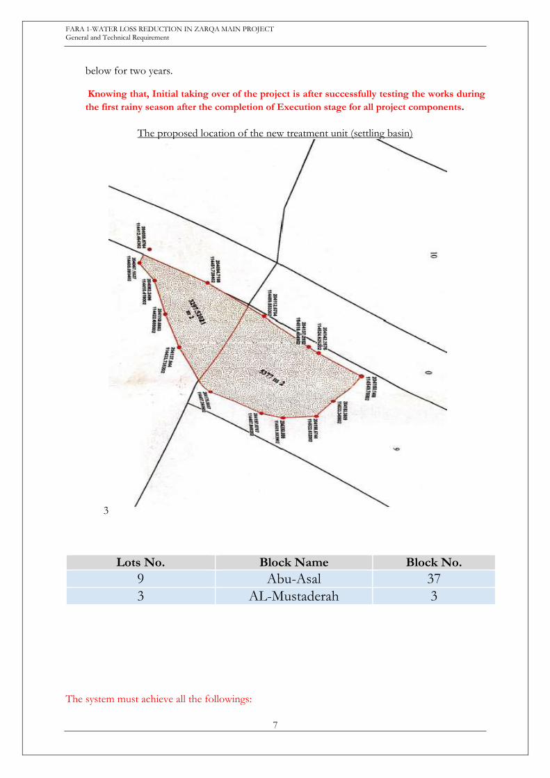
The proposed location of the new treatment unit (settling basin)
3
Lots No. Block Name Block No.
9 Abu-Asal 37
3 AL-Mustaderah 3 The system must achieve all the followings:
FARA 1-WATER LOSS REDUCTION IN ZARQA MAIN PROJECT General and Technical Requirement
8
- Adequate to treat 2000 m3/hr.
- Achieves a minimum of 90% turbidity removal, noting that the turbidity value would
possibly reach to 5000 NTU without losing water
- Ensures adequate flushing when required.
- Be able to isolate the Wadi water from the plant while keeping the Zara pump station
source incoming when required.
- Ensure inlet flow control and measurement from Wadi Zarqa Ma’in
- Ensure gravity flow
- Can be operated safely and all components/units can be reached safely by operators and
equipment if required.
- All used equipment and material shall be of the highest quality in the market and shall be
suitable for the intended use.
- The contractor is responsible for conducting all hydraulics & hydrological needed studies.
- The contractor is responsible for collecting of samples and measuring of turbidity values.
- Providing an operational laboratory items on site, including the necessary equipment and
necessary glassware
The necessary equipment consisting of, but not limited to, the following main components:
✔ Different types of glassware’s Gradated cylinders, beakers, bottles,
✔ Bench top Turbidity meter
✔ Laboratory Balance analytical (ELECTRONIC SCALE)
✔ PH meter with bench top
✔ THERMOMETER
✔ Jar test apparatus with 6 mechanical stirrers
- Design, built store for purpose of chemicals storage on site
- Achieves all requirements describes in the contract of this project.
The scope of work of the Contractor shall include, but not limited to, the design, supply,
installation, execution, testing, commissioning, training and operation of all the works for two
years. Operation will be just during the rainy season (rainy season from beginning of October to
the end of April), and subjected to Miyahuna requested during the defect notification period.
Initial taking over of the project is after successful testing the works during the first rainy
season after the completion of Execution stage for all project components.
The works include the following components:
● Chemically enhanced raw water treatment tanks and system of 2000 m3/hr capacity.
● Sluice gate at the inlet of the 900 mm pipe.
● Flushing sluice gate (1 m *1 m) at the weir intake area.
● Atoumatic Fine screen of 6mm bar spacing.
● 900 mm Flow control valve (with actuator)
● All connecting piping and structures between the treatment units.
● All required connecting piping and structures to the existing structures, water pipes and
flushing lines.

FARA 1-WATER LOSS REDUCTION IN ZARQA MAIN PROJECT General and Technical Requirement
9
● Replacement of the existing flushing GRP pipes (1200 mm diameter (114 m length) and
1500 mm diameter (58 m length))
● Refurbishment of 8 sluice gates and complete replacement of 2 sluice gates. The gates are
located in two different locations; Zarqa Ma’in and Zarqa weir location.
● Access road to the weir area of approximately 200 meters.
● Walk way to equipment of approximately 200 meters.
● Electromechanical works in two different locations; Zarqa Ma’in pumping station and Zara
Main pumping station.
FARA 1-WATER LOSS REDUCTION IN ZARQA MAIN PROJECT General and Technical Requirement
10
2. General Requirements
The Contractor shall cover the following requirements and activities. The Contractor shall carry
out any further activities that he believes are necessary to complete his obligations, these activities
will be considered as an integral part of his obligations.
2.1 Temporary Facilities and Controls
The works shall consist of the provision of Employer’s and Engineer’s Site offices and facilities by erection a prefabricated building at the discretion of the Engineer, including furnishing and maintaining, for the contract , all as per the documents and specifications.
2.2 Drawings and Reports
Contractor's Design Report and Drawings: The Contractor shall prepare and submit detailed design report and all civil, structural, architectural, mechanical, and electrical drawings for all required works. These drawings shall include but not limited to the following:
1. Structural Drawings
a) General notes and details.
b) Foundations plans, details, and sections.
c) Slabs layout, beams details, and columns details.
d) Walls details and sections.
e) Special structural details.
f) Any other drawings suggested by the Contractor or requested by the Engineer.
2. Architectural Drawings
a) Site topography plans.
b) Any other drawings suggested by the Contractor or requested by the Engineer.
3. Mechanical Drawings
a) Mechanical legend and abbreviations.
b) Site plan piping routing layout.
c) Building and process plans and sections, .. etc.
d) Schematic diagrams for the piping and other systems.
e) Surge equipment’s layout and sections.
f) Connection details.
g) Typical installation details.
h) Building services drainage plans.
i) Building services Domestic water system plans and schematic diagrams.
j) Building services firefighting plans.
k) Building services ventilation and air conditioning plans.
l) Building and process schedules of equipment.
m) Final process flow diagram.
n) Any other drawings suggested by the Contractor or requested by the Engineer.
4. Electrical Drawings
a) Electrical legend and abbreviations.
b) Cables routings site layout.
FARA 1-WATER LOSS REDUCTION IN ZARQA MAIN PROJECT General and Technical Requirement
11
c) External lighting site layout.
d) Electrical panels layout outdoor.
e) ELCB details.
f) Earthing layout including locations of earthing pits, main and round earth conductors.
g) Power single line diagrams.
h) Cables schedule.
i) P&IDs.
j) PLC Single line diagram and I/Os schedules.
k) SCADA system architectural arrangement.
l) Electrical details for trenches, manholes, lighting poles, cables installations, earthing,
lightning, and any other details requested by the Engineer.
m) Any other drawings suggested by the Contractor or requested by the Engineer.
The Contractor shall provide, install, execute, test and commission the works which are needed as per his design and Employer’s requirements.
Contractor's Shop Drawings: Contractor should submit all detailed shop drawings for any required works after achieving approvals on the design drawings. Approval on the shop drawings should be achieved.
Contractor's as Built Drawings: Contractor should submit all as Built drawings for any required works after finishing the execution of works. Approvals on the as Built drawings should be achieved.
FARA 1-WATER LOSS REDUCTION IN ZARQA MAIN PROJECT General and Technical Requirement
12
3. Process works and Design Criteria
The contractor shall design, install, execute, test, commission and operate the treatment plant for
two years. The system shall be adequate to treat 2000 m3/hr, to achieve a minimum of 90%
turbidity removal, to isolate Wadi water when required, to ensure flow control and measurement
and to ensure adequate flushing when required.
The Contractor shall prepare the detailed mechanical and equipment design drawings,
calculations and providing, installing, executing, testing and commissioning of the mechanical
and equipment works which include but not limited to the followings:
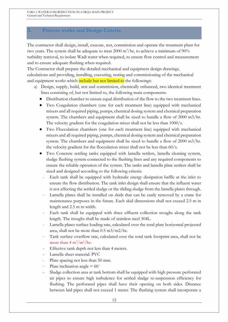
a) Design, supply, build, test and commission, chemically enhanced, two identical treatment
lines consisting of, but not limited to, the following main components:
● Distribution chamber to ensure equal distribution of the flow to the two treatment lines.
● Two Coagulation chambers (one for each treatment line) equipped with mechanical
mixers and all required piping, pumps, chemical dosing system and chemical preparation
system. The chambers and equipment shall be sized to handle a flow of 2000 m3/hr.
The velocity gradient for the coagulation mixer shall not be less than 1000/s.
● Two Flocculation chambers (one for each treatment line) equipped with mechanical
mixers and all required piping, pumps, chemical dosing system and chemical preparation
system. The chambers and equipment shall be sized to handle a flow of 2000 m3/hr.
the velocity gradient for the flocculation mixer shall not be less than 60/s.
● Two Concrete settling tanks equipped with lamella settlers, lamella cleaning system,
sludge flushing system connected to the flushing lines and any required components to
ensure the reliable operation of the system. The tanks and lamella plate settlers shall be
sized and designed according to the following criteria:
- Each tank shall be equipped with hydraulic energy dissipation baffle at the inlet to
ensure the flow distribution. The tank inlet design shall ensure that the influent water
is not affecting the settled sludge or the sliding sludge from the lamella plates through.
- Lamella plates shall be installed on skids that can be easily removed by a crane for
maintenance purposes in the future. Each skid dimensions shall not exceed 2.5 m in
length and 2.5 m in width.
- Each tank shall be equipped with three effluent collection troughs along the tank
length. The troughs shall be made of stainless steel 304L.
- Lamella plates surface loading rate, calculated over the total plate horizontal projected
area, shall not be more than 0.5 m3/m2/hr.
- Tank surface overflow rate, calculated over the total tank footprint area, shall not be
more than 4 m3/m2/hr.
- Effective tank depth not less than 4 meters.
- Lamella sheet material: PVC
- Plate spacing not less than 50 mm.
- Plate inclination angle = 60˚
- Sludge collection area at tank bottom shall be equipped with high pressure perforated
air pipes to ensure high turbulence for settled sludge re-suspension efficiency for
flushing. The perforated pipes shall have their opening on both sides. Distance
between laid pipes shall not exceed 1 meter. The flushing system shall incorporate a
FARA 1-WATER LOSS REDUCTION IN ZARQA MAIN PROJECT General and Technical Requirement
13
sludge re-suspension air blower of more than 1500 m3/hr capacity. Flushing gates
shall be connected to the existing flushing lines.
- The contractor shall consider in the design that water flow shall be by gravity.
- After treatment, the treated effluent shall flow to the existing storage tank. All required
works and pipes to convey the water to the storage tank by gravity is part of the
contractor’s scope of work.
- The inlet to the new treatment works will be located at the exit of the existing settling
tanks. The design and construction of the connection works between the existing
settling tanks and the new works is part of the contractor’s scope of work.
b) Replace the existing main GRP flushing lines. The diameter and approximate length for
the required new pipes are 1200mm diameter * 114 m and 1500 mm diameter * 58 m. The
attached Annex 1(in volume 4) contains a summary of existing GRP flushing lines locations
included in this scope of work. The pipeline shall be provided with proper bedding, well
supported and outer protection shall be provided. Fittings, tees and connections to the
existing manholes and other pipes and structures are part of the contractors’ scope of work.
c) Replace the sluice gate at the inlet of the 900 mm pipe with a motorized sluice gate to
ensure that the station is isolated from the Wadi at flooding events. When the gate is shut,
the only source of water entering the pumping station/ treatment units is that from Zara.
d) Replace the flushing sluice (1 m *1 m) gate at the bottom of the weir with a motorized
sluice gate. This gate will be opened at flooding events to ensure that sediments are not
accumulating at the weir area.
e) Design, supply, install and commission a 6 mm bar spacing fine stainless-steel screen at the
inlet of the primary treatment works. The screen shall be equipped with automatic cleaning
device. A suitable screening wheeled bucket shall be provided by the contractor.
f) Design, supply, build and commission a flow control valve and flow meter on the 900 mm
line at the inlet of the works to allow the operators to control the water flow rate entering
treatment units. The flow meter shall be electromagnetic water meter type for raw water
measurement with accuracy (Max. Permissible error) ±0.5% of rate. Provisions should be
made to allow the operators to direct any extra flow not going to treatment units (exceeding
plant capacity) to the wash out line. The design and installation of the connection pipes to
the wash out lines are part of the contractor’s scope of work.
g) Design and build an access road to the weir to allow for the safe movement of heavy
equipment (Excavator) to reach the weir and remove the sediments whenever needed.
Approximate length of the access road is 200 m.
h) Design and build a safe walkway for the workers to access the wear and all installed
equipment safely. The approximate length of the walkway is 200 m.
i) The refurbishment or complete replacement of 10 sluice gates existing in two location;
Zarqa Ma’in pumping station and Zarqa weir location. The attached Annex 1 contains a
summary of gates included in this scope of work and details of an initial general inspection.
The scope of works of the contractor includes the inspection, assessment, design, supply,
removal of existing parts, installation, testing and commissioning of all the gates in the list.
The details in annex 1 shall be considered as the minimum works that can be performed
by the contractor to ensure the successful operation of the gates.
FARA 1-WATER LOSS REDUCTION IN ZARQA MAIN PROJECT General and Technical Requirement
14
The measurements, specs and refurbishment details provided in Annex 1, are for general
guidance only and they might contain inaccurate measurement, dimensions or assessments.
The contractor shall do his own inspection and assessment of the gates.
Where the gate is mentioned in Annex 1 as to be replaced, then a new gate shall be installed
in place of the old gate. The scope of work includes the removal of all the fixed and moving
parts of the existing gate.
When the gate is mentioned in annex 1 as to be refurbished, then the Contractor shall
perform his own inspection and assessment and perform all required works and supply
install and commission all required parts to ensure that the gate is working correctly. The
refurbishment works mentioned in Annex 1 shall be considered as minimum requirements.
j) Electromechanical works in two locations Zarqa Ma’in pumping station & Zara Ma’in
pumping station.
Description for needed electromechanical works at Zarqa-Ma’in Pumping Station:
Zarqa-Main Pump station consists of four horizontal pumps. The water is pumped into Amman.
The feeding Power for pumps is Medium voltage (6.6kv) rate.
✔ Supply and install new automated control system to operate, monitor and control the
station locally and remotely from the SCADA including all the necessary protections for
pumps.
✔ Motor protection unit is already installed and its type is (ABB REM 543) and no need to
replace it, just connect it to the new system, the signals and readings from the REM 543
include but not limited are:
1- Under/over voltage
2- Under/over current
3- Unbalance voltage and current
4- Pump bearing temperature
5- Motor winding and bearing temperature
*Note: Any protection or reading that are not activated on REM 543, the contractor
is responsible to configure and activate these signals
*Note: The contractor is responsible of connecting these signals either if he will use
the existing cables or to install new cables if he needs that.
✔ Pump protections (electrical & water protections) must be activated both locally (on
MCC) and remotely (on PLC).
✔ Supply and install a new PLC controller plus 12 inch HMI to monitor and operate the
station by the operator including all electrical works.
✔ The PLC (RTU) must transfer all station signals to the Main SCADA system in Dabouq
SCADA center, knowing that, the main SCADA system is already installed and under
operating and warranty by FARA 9 contractor, so when adding this site to the SCADA
system, an arrangement must be done with FARA9 contractor and all the related cost
must be reflected without affecting on warranty. So it is requested to design and install
communication system and the suggested system is 4G mobile, but another reliable
communication system like microwave can be selected.
✔ Supply, Install, and commission Butterfly motorized control valve for the main discharge
pipe DN: 900mm /PN: 25 bar.
FARA 1-WATER LOSS REDUCTION IN ZARQA MAIN PROJECT General and Technical Requirement
15
✔ Supply, Install, and commission Butterfly valve for the pumps suction pipe DN: 500mm
/PN: 16 bar (Quantity: 4).
✔ Supply and install Butterfly motorized control valve for the pumps discharge pipe DN:
450mm /PN: 25 bar. (Quantity: 4).
✔ Supply, Install, and commission circuit breaker ABB type (HD4/P 12.06.25) 50 Hz
frequency, 630 A rated current, 12 KV rated voltage. (Quantity:1)
✔ Supply, Install, and commission ABB contractor (UniGear type ZVC) 50-60 Hz
frequency, 7.2 KV rated voltage and 400 A rated operational current.(Quantity:3)
✔ Supply, Install, and commission the following instruments to be implemented in the
station, which are:
● For each pump, two pressure switches, one on the suction side and the other on the
delivery side
● For each pump, No-flow
● For each pump, two Pressure transmitters (analog), one on the suction side and the other
on the delivery side.
● On the main suction pipe, a pressure transmitter, and another one for the main delivery
side.
● For each pump, all needed electrical, mechanical, and civil works and activation for all
motor and pump thermal sensors on local and remote mode.
● Radar or laser level measuring sensor to monitor the reservoir water level.
✔ Supply, Install, and commission two Drainage Submersible pumps systems (Duty and
stand by) with all needed accessories (auto and manual).
Description for needed electromechanical works at Zara-Ma’in Pumping Station:
Zara-Main Pump station consists of three horizontal pumps. The water is pumped into Zarqa'a
Ma’in. The feeding Power for pumps is low voltage (400V) rate.
✔ Supply, Install, and commission new automated control system to operate, monitor and
control the station locally and remotely from the SCADA including all the necessary
protections for pumps.
✔ Supply, Install, commission and activate Motor protection modules (qty:3) with all
electrical works and adding current transformers (CTs),
Motors & pumps protections at least must contain the following:
1- Under/over voltage
2- Under/over current
3- Unbalance voltage and current
4- Pump bearing temperature
5- Motor winding and bearing temperature
*Note: The contractor is responsible of connecting these signals either if he will use the
existing cables or to install new cables if he needs that
✔ Pump protections (electrical & water protections) must be activated both locally (on
MCC) and remotely (on PLC).
FARA 1-WATER LOSS REDUCTION IN ZARQA MAIN PROJECT General and Technical Requirement
16
✔ Supply, Install, commission new PLC controller plus 12 inch HMI to monitor and
operate the station by the operator including all electrical works.
✔ Pump protections (electrical & water protections) must be activated both locally (on
MCC) and remotely (on PLC).
✔ The PLC (RTU) must transfer all station signals to the Main SCADA system in Dabouq
SCADA center, knowing that, the main SCADA system is already installed and under
operating and warranty by FARA 9 contractor, so when adding this site to the SCADA
system, an arrangement must be done with FARA9 contractor and all the related cost
must be reflected without affecting on warranty. So it is requested to design and install
communication system and the suggested system is 4G mobile, but it can be suggested
other reliable communication system like microwave.
✔ Supply and install main suction header 600mm with butterfly valve 600 mm and install a
strainer, and main discharge header 500mm with butterfly valve 500 mm discharge pipe.
✔ Supply, Install, and commission the following instruments to be implemented in the
station, which are For each pump, two pressure switches, one on the suction side and the
other on the delivery side
● For each pump, No-flow
● For each pump, two Pressure transmitters (analog), one on the suction side and the other
on the delivery side.
● On the main suction pipe, a pressure transmitter, and another one for the main delivery
side.
● For each pump, electrical works and activation for all motor and pump thermal sensors
on local and remote mode.
● Radar level measuring sensor to monitor the reservoir water level.
FARA 1-WATER LOSS REDUCTION IN ZARQA MAIN PROJECT General and Technical Requirement
17
4. Electrical Works Design Criteria
A. CONTRACTOR'S SCOPE OF WORK All electrical design works should be done upon the requirements of national technical specifications, in addition to the international codes and Client Requirements. These standards are:
1. General Technical Specifications for Buildings, Electrical Installations, Part 3 Ministry of
Public Works and Housing, Jordan.
2. Jordanian Electrical Codes.
3. American National Standard Institute (ANSI).
4. Institute of Electrical and Electronics Engineers (IEEE).
5. National Electrical Code (NEC).
6. National Electrical Manufacturers Association (NEMA).
7. Underwrites’ Laboratories (UL).
8. International Electro-technical Commission (IEC) Standards.
9. The Client Requirements.
10. In addition, Electricity Distribution Company (EDCO) and the public guidelines and
regulations must be observed.
Contractor shall prepare the detailed electrical design drawings, provide, install, execute, test and commission the electrical works for the pump station as follows:
a. Power Supply
● Electrical power calculations and demand to insure that the feed electrical supply is
sufficient to serve the new demand.
● Electrical calculations for the main transformer capacity cable sizing and upgrading
requirements
● The new electrical items shall be powered from the existing/nearest power supply, maybe
existing main distribution board. Contractor shall check with the project Client to choose
the power source for the new facilities.
● The contractor shall make all necessary communications with the Electricity Company
(EDCO) to supply the site with electrical current with the required capacity and to
provide all electric panels, cables, devices and equipment needed to the new pumping
station and to the distribution and operation panels for existing tower pumps and all
needed Cables, instruments, protection relays, trenches, manholes, electrical and civil
works, and according to the recommendations of the supervisory committee.
● Supply and Install new electrical panels (Main Breaker as EDCO specifications and
requirements, Main Distribution Panel, Operation Panels (Variable frequency Drive) and
all needed Cables, instruments, protection relays, trenches, manholes, electrical and civil
works.
b. Existing Gates and Actuators
1. Supply, install, test and commission new motorized inlet gate to replace the existing old
one on the 900mm pipe.
FARA 1-WATER LOSS REDUCTION IN ZARQA MAIN PROJECT General and Technical Requirement
18
2. Supply, install, test and commission new motorized flushing gate to replace the existing old
one as the mentioned specifications.
c. Main Distribution Board
Supply, install, test and commission new main distribution board (MDB) to be installed near the new treatment structures or could be installed inside the nearest electrical room if any. Contractor is needed to verify the site and decide where to install this new main distribution board. The main distribution board shall include compartment for the main moulded case circuit breaker incomer, compartment for the capacitor bank, and compartment for outgoing moulded case circuit breakers. All power, control and monitoring devices, indication lamps as per specifications.
SCADA & PLC & RTU
Supply, install, test and commission new SCADA system & HMI. The new SCADA system and HMI shall include monitor screens, run time, development & engineering software licenses,. Contractor shall submit to the engineer the new SCADA & HMI structure.
The SCADA software must be installed and developed on a laptop and licensed. The laptop specs must be at least core i7 10th generation and 16 giga byte ram and 15 inch (at least) screen size. The SCADA on The laptop must be capable of monitor & control the whole station via VPN technology or any other method.
PLC programming software must be installed on other laptop and licensed for any future maintenance. All the required software for all devices must be installed and licensed on this laptop. The laptop specs must be at least core i7 10th generation and 16 giga byte ram and 15 inch (at least) screen size.
So, the SCADA system and HMI in this project must contain at least the following: 1- Zara Ma’in station (Control & monitoring) 2- Zarqa’a Ma’in station main pumps (control & monitoring) 3- Zarqa’a Ma’in pre-treatment station with all gates and valves (control & monitoring) - Note that, it is meant of “SCADA” in this section, the new SCADA on the laptop - Note that, the mentioned stations before must be connected to the main SCADA in
Dabouq.
Programmable Logic Controller (PLC) / REMOTE TELEMENTRY UNIT (RTU)
There are three PLC panels to be installed in this project:
1- PLC panel in Zarqa’a Ma’in station to control & monitor the main station pumps and
transfer the station signals to the HMI & the new SCADA on the laptop and Dabouq
main SCADA.
2- PLC panel in Zarqa’a Ma’in pre-treatment station to control & monitor the pre-treatment
process and gates and valves with all related electrical & mechanical machines and
equipment and transfer the station signals to the HMI & the new SCADA on the laptop
and Dabouq main SCADA.
3- PLC panel in Zara Ma’in station to control & monitor the station pumps and transfer the
station signals to the HMI & the new SCADA on the laptop and Dabouq main SCADA.
d. Control Panels/PLCs
1. Supply, install, test and commission a control panel to control the flushing gate (CP-FG)
to provide power and control the operation of the motorized new flushing gate for the
weir, and to control the inlet gate (CP-IG) to provide power and control the operation of

FARA 1-WATER LOSS REDUCTION IN ZARQA MAIN PROJECT General and Technical Requirement
19
the motorized new inlet gate for the pump station and to control the flow control valve
(CP-FCV) to provide power and control the operation of the flow control valve, flow meter
etc which will be installed on the 900mm inlet to the pump station and to control the pre-
treatment station to provide power and control the operation of the inlet mechanical
screen, pumps’ motors, mixers, chemical dosing system and chemical preparation system
for the two coagulation and two flocculation chambers.
The control panel enclosure shall have a section which comprises a programmable logic
controller (PLC).
The functions of the PLC are:
1- To monitor and control the operation and status of the motorized flushing gate.
2- To monitor and control the operation and status of the motorized inlet gate
3- To monitor and control the operation and status of flow control valve, flow meter
etc. which will be installed on the 900mm inlet to the pump station
4- To monitor and control the operation and status of the electromechanical equipment
such as mechanical fine screen ,pumps’ motors, mixers, chemical dosing system and
chemical preparation system for the two coagulation chambers and two flocculation
chambers, two settling tanks, instruments, level meters, flow meters, actuated valves
etc.
● Contractor shall prepare full detailed design for the PLC and include all I/Os which are
needed. The submitted type and functionality of the PLC is subject to the Engineer's
approval.
Contractor is needed to verify the site and decide where to install this new control panel
(CP).
2. Supply, install, test and commission settling tank1 control panel (CP-ST1) to provide power
and control the operation of the electrical machines of settling tank1. This control panel
shall be installed on the bridge of settling tank1.
3. Supply, install, test and commission settling tank2 control panel (CP-ST2) to provide power
and control the operation of the electrical machines of settling tank2. This control panel
shall be installed on the bridge of settling tank2.
4. Each Control panel shall have busbar, main moulded case circuit breaker, Soft starter or
Variable Frequency Drive(VFD) depends on the application ,UPS, power, control and
monitoring devices, three-way selector switches (Local, Off, Remote), On/Off push
buttons, indication lamps as per specifications.?
5. Each control panel shall be supplied by power from the main distribution board.
6. All signals shall be received/transmitted to the related PLC and after that transmitted to
the SCADA systemand HMI. Contactor is responsible to provide and install all related
power, control and signal cables between the pumps, motors, mixers, instruments and the
related control panels and PLC.
7. The PLC shall be linked with the SCADA system and HMI

FARA 1-WATER LOSS REDUCTION IN ZARQA MAIN PROJECT General and Technical Requirement
20
8. The minimum needed I/Os for the pumps, mixers and related devices and instruments are
shown in the I/Os table, Contractor maybe asked to add other I/Os, the added I/Os are
the responsibility of the Contractor and deem to be included in the unit price of the I/O
list.
9. Contractor shall prepare a list of the digital and analogue inputs/outputs which are related
to the pumps, motors, mixers and related devices and instruments with additional spare
I/Os not less than 25% of the used I/Os.
10. Each PLC shall be supplied by power from UPS installed inside the control panel enclosure.
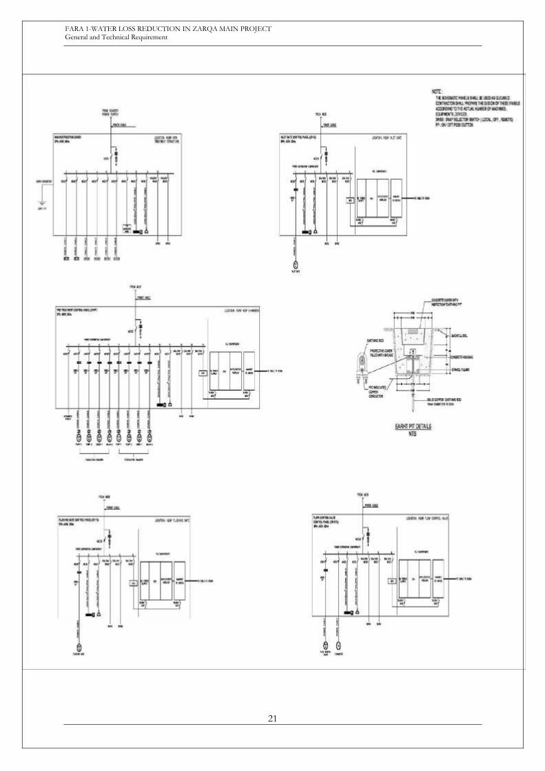
11. The following figure in the next page shows the schematic diagrams for the panel
boards. These schematics shall be used as guidance. Contractor shall prepare the design
of these panels according to the actual number of machines, equipment devices
Note 1: This is a suggested PLC system structure, any other structure can be used, but
note that, it is required only to install one CPU with any required extensions and I/Os
Note 2: All the station signals must be connected to the SCADA on a laptop as described
in the SCADA section and to be connected to the main SCADA in Dabouq, these signals
transfer must be done with arrangement with FARA 9 Contractor with reflecting all costs.
FARA 1-WATER LOSS REDUCTION IN ZARQA MAIN PROJECT General and Technical Requirement
21

FARA 1-WATER LOSS REDUCTION IN ZARQA MAIN PROJECT General and Technical Requirement
22
Figure 5-1 :Schematic Diagrams for the Panel Boards
12. Local Control Panels
1. Supply, install, test and commission local control panel (LCP) for each mixer and pump of
the two coagulation chambers. Each LCP shall be installed near the related machine and
supplied by power from the pre-treatment control panel (CP-PT). Each local control panel
shall have moulded case circuit breaker, emergency stop, three-way selector switch (Local,
Off, Remote), On/Off push buttons, indication lamps as per specifications.
2. Supply, install, test and commission local control panel (LCP) for each mixer and pump of
the two flocculation chambers. Each LCP shall be installed near the related machine and
supplied by power from the pre-treatment control panel (CP-PT). Each local control panel
shall have moulded case circuit breaker, emergency stop, three-way selector switch (Local,
Off, Remote), On/Off push buttons, indication lamps as per specifications.
e. Earthing System
Supply, install, test and commission all needed material and equipment for construction an
earthing system for the main distribution board as specified to achieve an earth resistance not
more than 2 ohms. Work includes earthing rods, earthing conductors, earthing pits and any
accessories needed.
Contractor shall submit earthing calculations using appropriate calculation method to achieve the
number of earthing rods and earthing pits in addition to the size of earthing round conductors.
f. Main and Branch Low Voltage Power Cables
1. Supply, install, test and commission power cable between the existing power supply
(existing electrical panel) and the main distribution board (MDB) in addition to the branch
power cables between the control panels and the related motors.
2. Supply, install, test and commission all power cables between the main distribution board
(MDB) and the flushing gate control panel (CP-FG).
3. Supply, install, test and commission all power cables between the main distribution board
(MDB) and the inlet gate control panel (CP-IG).
4. Supply, install, test and commission all power cables between the main distribution board
(MDB) and the flow control valve control panel (CP-FCV).
5. Supply, install, test and commission all power cables between the main distribution board
(MDB) and the pre-treatment control panel (CP-PT)
6. Supply, install, test and commission all power cables between the main distribution board
(MDB) and the two control panels of the settling tanks. (CP-ST1) and (CP-ST2)
7. Supply, install, test and commission all power cables between the pre-treatment control
panel (CP-PT) and the related local control panels.
8. Supply, install, test and commission all branch power cables between the settling tanks
control panels and the related machines such as mixers and scraper.
9. Supply, install, test and commission all branch power cables for all electrical panels, devices,
motorized gates, actuated valves and package units …etc from the related control/local
control panels.

FARA 1-WATER LOSS REDUCTION IN ZARQA MAIN PROJECT General and Technical Requirement
23
10. All power cables installed inside water shall be submerged, rubber type suitable for
submersible purposes.
11. Cables inside electric and pumps rooms (if any) shall be installed in concrete trenches.
When cables leave the trench and connected to the terminal box of the motor, they should
be installed on galvanized cable ladder or galvanized covered cable tray.
12. Main power cable from the existing power supply to the main distribution board shall be
multicore, copper conductor, XLPE insulated, steel wire armoured, and PVC sheathed.
13. Indoor power cables shall be multicore, copper conductor, XLPE insulated, and PVC
sheathed non armoured.
14. Outdoor power cables shall be multicore, copper conductor, XLPE insulated, and PVC
sheathed non armoured.
15. All outdoor power cables shall be installed inside UPVC pipes.
16. All indoor and outdoor cable supporting systems such cable ladders, cable trays, cable
trunks, PVC and galvanized conduits shall be included in the price of the cables.
17. Contractor shall use suitable software and submit voltage drop, short circuit and cables
sizing calculations for all electrical loads taking into consideration that the voltage drop
shall not exceed 4%.
g. Control, Signal and Instrumentation Cables
Supply, install, test and commission all control, signal and instrumentation cables between the
motors, pumps, mixers, instruments and measuring devices and the related electrical and PLC
panels.
h. Trenches for Power Cables
1. Indoor concert trenches shall be used to install power cables between the control panels
and the related motors. These indoor concrete trenches shall be covered by galvanized
chequer plates.
2. Outdoor cables trenches shall be constructed including excavation with size (Depth X
Width) (80X60) cm, laying of cables inside100mm UPVC conduits, add soft sand below
and above the UPVC conduit, solid concrete blocks, warning tape, and finally compacted
backfilling.
i. Electrical Manholes
Construct electrical concrete manholes (80x80x80) dimensions for outdoor installation cables with
medium duty steel covers. Spacing between manholes shall not be more than 50meters.
j. External Lighting
1. Supply install test and commission external lighting poles along the access road to the weir.
2. Supply install test and commission external lighting poles along the safe walkway for the
workers to access the wear.
3. Supply install test and commission external lighting poles around the new process
structures such as the Distribution Chamber, Coagulation Chambers, Flocculation
Chambers, Settling Tanks and other needed locations.
FARA 1-WATER LOSS REDUCTION IN ZARQA MAIN PROJECT General and Technical Requirement
24
4. Contractor shall prepare external lighting design for the above-mentioned locations and
roads using 7 meters height lighting poles with 100watt LED luminaire. The spacing
between lighting poles shall be 25 meters.
5. Supply install test and commission external lighting control panel (ELCP) including main
MCCB incomer, number of outgoing MCCBs with rating not less 25 Amp., contactor,
photocell, and timer with 3-way selector switch (Manual, Off, Automatic). Each circuit shall
serve 10 lighting poles as maximum.
6. The ELCP shall be supplied by power from the main distribution board using 4x16 mm2
CU/XLPE/PVC cable inside 50 mm UPVC conduit.
7. Supply install test and commission power cables with size not less than 4x16 mm2
CU/XLPE/SWA/PVC from the ELCP and poles and between the lighting poles.
k. Lighting Calculations
Lighting calculation software (DIALux) shall be used for the external lighting to determine the adequate number of lighting fixtures and verify the LUX level. Instruments and Measuring Devices Supply, install, test and commission all needed measuring devices such as flow meters, level
meters, pressure transmitters, flow switches etc. All power and control wiring between these
devices and their related panels and PLC shall be provided and executed by the Contractor. All
instruments shall be supplied by power from the UPS of the related control panel. The following
instruments shall be installed:
1. Pressure transmitter (4-20 mA) on the main suction pipe of each set of pumps.
2. Pressure transmitter (4-20 mA) on the main discharge pipe of each set of pumps.
3. Pressure transmitter (4-20 mA) on the suction pipe of each pump.
4. Pressure transmitter (4-20 mA) on the discharge pipe of each pump.
5. Flow switch on the suction pipe of each pump.
6. Radar level or laser level meter for each chamber, tank, reservoir …etc.
l. Valves /Gates with electrical actuators
Some valves /gates are electrically operated and equipped with electrical actuators as per the
mechanical drawings and details. All power and control wiring between these actuators and their
related panels and PLC shall be provided and executed by the Contractor.
Each valve/gate actuator must incorporate local controls for Open, Close and Stop operation
and a Local/Stop/Remote mode selector switch and working as follows:
1. Local mode: The valve can be opened/closed from the site only via local controls.
2. Stop mode: The valve is stopped, and no action can be done either locally or remotely.
3. Remote mode: The valve can be opened/closed via SCADA selector soft key (Auto,
Manual).and shall have two options:
● Option 1: In the Remote mode, and the SCADA selector soft key in Auto mode, the
valve shall be opened/closed automatically according to the operation of the pump or
manually via SCADA selector soft key.
● Option 2: In the Remote mode, and the SCADA selector soft key in Manual mode,
the valve shall be opened/closed manually by the SCADA operator.
m. Other Electrical Works

FARA 1-WATER LOSS REDUCTION IN ZARQA MAIN PROJECT General and Technical Requirement
25
Any other electrical works not described above but deemed necessary for the satisfactory
completion of the works. Contractor to specify, detail and submit breakdown for these items and
works.
FARA 1-WATER LOSS REDUCTION IN ZARQA MAIN PROJECT General and Technical Requirement
26
5. SITE WORKS AND LANDSCAPE
This section addresses design principles and criteria adopted to ensure a safe and efficient site for
site components, vehicular and pedestrian traffic. Storm water runoff management must be
effectively incorporated into the project for irrigation and harvesting.
The following are site components to be considered during the design stages:
5.1 Roads
5.1.1 Roads and Site Grading Requirements
The contractor shall be committed to the technical requirements of roads and grading work, as
per the following:
● The design of roads shall be carried out utilizing as a guide, the "Policy of Geometric
Design of Highway and Streets – AASHTO 2011".
● The general specifications for road and bridge construction shall be those of the Ministry
of Public Works and Housing (MPWH) "Specifications for Highway and Bridge
Construction – 1991". Special specifications should be prepared to account for
modifications/additions to the general specifications.
5.1.2 Geometric design
The geometric design criteria to be adopted for road design shall be:
● Design speed:
- 30km/hr min (lower speeds may be selected depending on available right of way,
pedestrian presence, adjacent development, and other area controls. All design elements
should encourage speeds generally not exceeding 50 km/hr.
● Sight distance:
- Stopping sight distance should range from 30 to 60 m depending on the design speed.
Design for passing sight distance is not applicable.
● Grades:
- The minimum longitudinal grade for roads should not be less than 0.3%. Max's grades
should not exceed 5.0%.
● Cross fall:
- As a guide, the normal cross fall (slope of the surface of the carriageway measured
normal to the centerline) should not exceed 2.0%. In wide parking areas and queuing
areas, the minimum cross slope shall be 0.5%.
● Super elevation
- Curves should be designed for a maximum super elevation rate of 2.0%. A rate of 4.0%
may be used when it is absolutely necessary.
- Width of roadway: The carriageway shall have sufficient width to meet the needs of the
future vehicle and pedestrian traffic. The minimum lane width shall be 3.6m for cars and
buses, and 4.0m for trucks. Where curbstone is used at the edges of the carriageway,

FARA 1-WATER LOSS REDUCTION IN ZARQA MAIN PROJECT General and Technical Requirement
27
then the curb should be offset by 0.3m on the left edge and 0.6m on the right edge
where no parallel parking is provided.
- The road reserve will be designed to take account of the location of existing and future
services, including drainage, overhead and underground utility services, and road
furniture including signs and lighting.
● Intersection design:
- The vehicle turning path design shall be specific to each intersection.
- The design shall cater to the future vehicle configuration. As a guide, the AASHTO WB-
19 shall be considered as a design vehicle.
5.1.3 Pavement and Materials
Pavement design: Road pavements shall be of the flexible type (asphalt concrete surfaces and
aggregate bases). The design shall be based on the "AASHTO Guide for Design of Pavement
Structures". Other methods may be used subject to the approval of the Employer.
The pavements layers shall include the following:
✔ Wearing layer a minimum thickness of 6 cm.
✔ Binder layer a minimum thickness of 7 cm.
✔ Base layer a minimum thickness of 20 cm.
✔ Subbase layer a minimum thickness of 20 cm.
✔ Topping layer a minimum thickness of 30 cm, (According to MPWH specification).
5.1.4 Roadside furniture
Marking and signing for roads shall conform to the "Manual on Devices & Manual on Traffic
control – 2003" issued by the Ministry of Public Works and Housing, and MUTCD if needed.
Guardrail shall be proposed at culverts and high fill sections more than 2m.
5.1.5 Surveying
The Contractor shall carry out a detailed topographical survey of the site prior to the detailed
design.
The survey works shall be as follows:
For roads:
▪ Projection the alignments of roads on the site, then adopt the survey work as section per
10m and the length of the section should be 30m.
For areas:
▪ Shall be a mesh with a grid of 10m.
▪ The Contractor will be responsible for the design details within the above technical
requirements. The technical requirements used in the design of roads, pavement,
grading, and earthworks, shall conform to the latest techniques while ensuring the use
of locally available materials. At all times a balance must be kept between capital and

FARA 1-WATER LOSS REDUCTION IN ZARQA MAIN PROJECT General and Technical Requirement
28
maintenance costs.
▪ In cases where the Contractor feels the need to adopt other international and regional
design standards, the supervision will be consulted for approval after presenting
adequate explanations.
▪ The International and regional specifications that may be consulted will include:
▪ AASHTO (American Association of State Highway and Transportation Officials);
5.1.6 British Standards.
Finally, the design standards for the different roads will be developed for discussion and approval
of the Engineer and Employer.
Parameters of particular importance will be:
5.1.7 Road type
▪ The degree of improvement required for existing horizontal and vertical alignment for
the existing road at the junction (if needed);
▪ Geometric layout of junctions;
▪ Safety measures to be introduced;
▪ Materials for construction;
▪ Roadside furniture.
5.1.8 Design of Vertical and Horizontal Alignments
The data captured during the field topographical surveys will be further processed by computer-
aided methods by Road Design software such as Civil 3D, in order to determine the existing
horizontal and vertical alignment parameters for the proposed design of the road in addition to
super elevation data, roadway templates incorporating widenings where required. The proposed
horizontal alignments will be detailed and calculated according to the design standards approved
by the Supervision.
In designing both the vertical and horizontal alignments, the Contractor will make sure to obtain
the optimum solution which will be in accordance with the required design standards and will take
into consideration factors such as climate, aesthetics, and costs.
Cross-sectional data perpendicular to this alignment will be derived from a 3D TIN (triangulated
irregular network) created from the X, Y, Z elements of the topographic surveys input into the
software. Accordingly, the vertical alignment will be calculated taking into consideration the
proposed drainage culverts.
The Project Director and the Highway Engineer would then modify this alignment to conform to
the proposed design parameters and present it to the Supervision for discussion and approval.
5.1.9 Pavement Design
Upon completion of the traffic assessment exercise (as explained later in this chapter) and with
the knowledge of the quality of naturally occurring gravels available, the in-situ subgrade

FARA 1-WATER LOSS REDUCTION IN ZARQA MAIN PROJECT General and Technical Requirement
29
characteristics, and the axle load restrictions applicable in Jordan, the Contractor will undertake
the pavement design taking into account inter-alia, the following important criteria:
▪ the pavement design must give the most appropriate solution at minimum cost and
based on local terrain, soil conditions, and vertical alignment;
▪ the pavement must be sound and balanced structurally to withstand the heavy load the
minimum applicable WB-12 regarding AASHTO;
▪ The pavement design must make full allowance for upgrading to meet the traffic growth
during its economic life, and minimum design life shall be 20 years.
5.1.10 Design Output
The output of the preliminary designs will be presented as follows: -
▪ Maps showing topographical survey strips containing the alignments.
▪ Road plans and profiles to a scale of 1:1000/1:100 (or as agreed with the supervision)
showing the proposed road center lines including the horizontal curve details, the road
longitudinal profiles, chainages of the cross-sections, drainage structures, right of way,
etc...
▪ Typical cross-sections showing the different dimensions and pavement.
▪ Cross-section drawings to a scale of 1:100 (or as agreed with the supervision).
▪ Bridges and culverts 1:100 (or as agreed with the supervision).
▪ Service utilities within the ROW needed to be relocated or protection.
5.1.11 Site Clearance and Earthworks
The contractor shall remove the materials and dispose of contaminated soil to the places
permitted by the competent authorities and according to their instructions.
Grading only those areas impacted by buildings, parking lots, and access roads are preferred. Provide construction staging areas to facilitate construction operations. Consider soil types, topography, etc. necessary to economize on construction costs in the design.
5.1.12 Storm Water Drainage
The contractor shall ensure that all roads are accessible and no rain water reaches any project
structure under the design storm. Storm water shall be conveyed safely, in either closed or open
conveyance systems, and be disposed properly to a natural water course outside the project site.
5.1.13 Design Rainfall Intensity
The design rainfall intensity shall be 41mm/hr.
5.1.14 Permitted water depth
Water depths in the roads shall not exceed 5cm at the design storm.

FARA 1-WATER LOSS REDUCTION IN ZARQA MAIN PROJECT General and Technical Requirement
30
5.1.15 Conveyance structures
Conveyance structures shall be designed with a 65% of its maximum capacity under the design
storm period.
5.1.16 Minimum and maximum velocities
The minimum conveyance velocity shall be 1.0m/s under the design storm flow rate and the
maximum shall not exceed 3.0m/s.
5.1.17 Entrance and outlet protections
Proper entrance and outlet protections shall be designed to avoid erosion or scour.
5.1.18 Rainfall-Runoff Modelling
The Rational Method shall be adopted to determine the peak discharges of runoff for the sub-
basins. This relation is presented in the following equation:
Where:
▪ C = The Runoff Coefficient, taken to be 0.8
▪ I = The Design Rainfall Intensity [mm/h]
▪ A = Catchment Area [km2]
▪ Qp = Peak flow rate (m3/s)
5.2 Existing Structures
All opening in existing walls should be done by specialist using professional techniques, but not
manually, and should be treated to prevent leakage.
All tie-ins and connections to existing piping and equipment should be done by specialists using
professional techniques.
FARA 1-WATER LOSS REDUCTION IN ZARQA MAIN PROJECT General and Technical Requirement
31
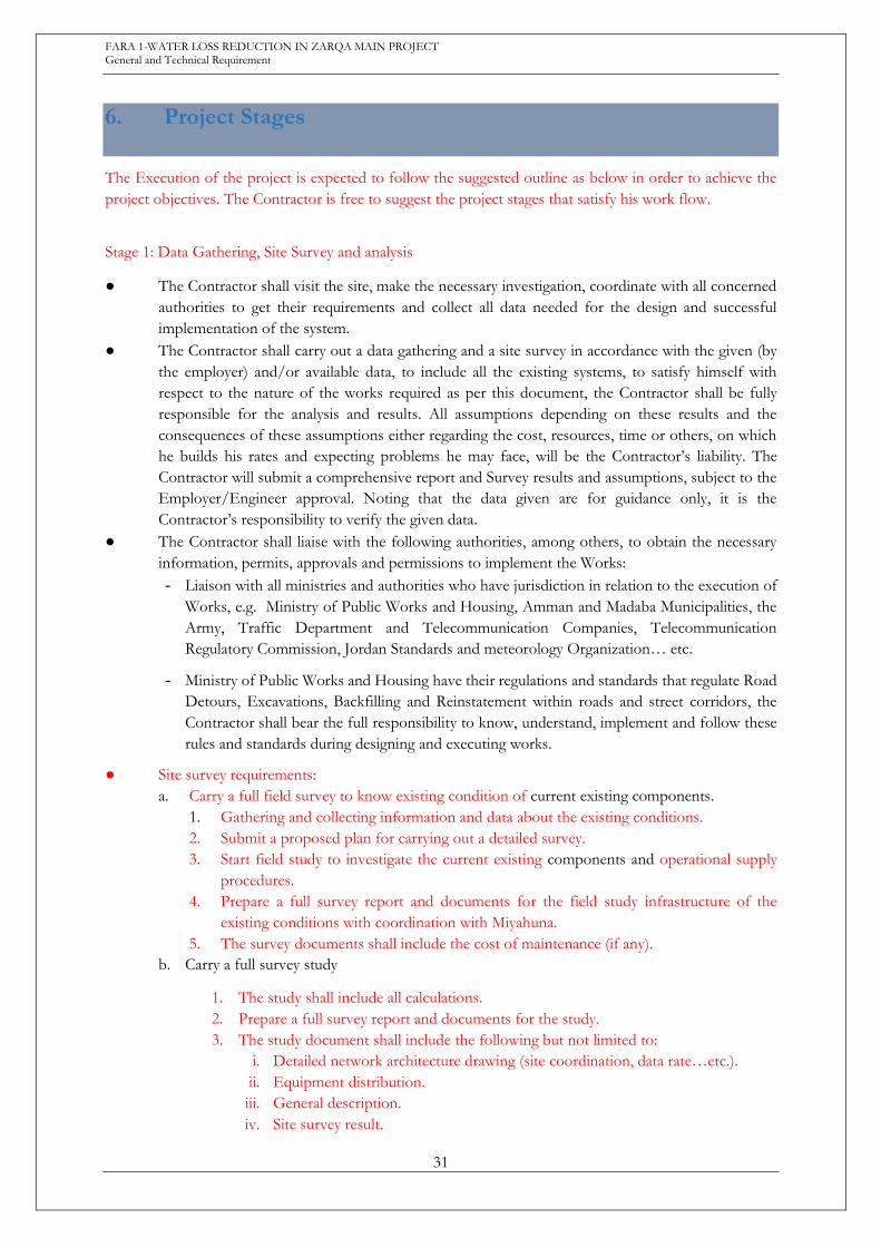
6. Project Stages
The Execution of the project is expected to follow the suggested outline as below in order to achieve the
project objectives. The Contractor is free to suggest the project stages that satisfy his work flow.
Stage 1: Data Gathering, Site Survey and analysis
● The Contractor shall visit the site, make the necessary investigation, coordinate with all concerned
authorities to get their requirements and collect all data needed for the design and successful
implementation of the system.
● The Contractor shall carry out a data gathering and a site survey in accordance with the given (by
the employer) and/or available data, to include all the existing systems, to satisfy himself with
respect to the nature of the works required as per this document, the Contractor shall be fully
responsible for the analysis and results. All assumptions depending on these results and the
consequences of these assumptions either regarding the cost, resources, time or others, on which
he builds his rates and expecting problems he may face, will be the Contractor’s liability. The
Contractor will submit a comprehensive report and Survey results and assumptions, subject to the
Employer/Engineer approval. Noting that the data given are for guidance only, it is the
Contractor’s responsibility to verify the given data.
● The Contractor shall liaise with the following authorities, among others, to obtain the necessary
information, permits, approvals and permissions to implement the Works:
- Liaison with all ministries and authorities who have jurisdiction in relation to the execution of
Works, e.g. Ministry of Public Works and Housing, Amman and Madaba Municipalities, the
Army, Traffic Department and Telecommunication Companies, Telecommunication
Regulatory Commission, Jordan Standards and meteorology Organization… etc.
- Ministry of Public Works and Housing have their regulations and standards that regulate Road
Detours, Excavations, Backfilling and Reinstatement within roads and street corridors, the
Contractor shall bear the full responsibility to know, understand, implement and follow these
rules and standards during designing and executing works.
● Site survey requirements:
a. Carry a full field survey to know existing condition of current existing components.
1. Gathering and collecting information and data about the existing conditions.
2. Submit a proposed plan for carrying out a detailed survey.
3. Start field study to investigate the current existing components and operational supply
procedures.
4. Prepare a full survey report and documents for the field study infrastructure of the
existing conditions with coordination with Miyahuna.
5. The survey documents shall include the cost of maintenance (if any).
b. Carry a full survey study
1. The study shall include all calculations.
2. Prepare a full survey report and documents for the study.
3. The study document shall include the following but not limited to:
i. Detailed network architecture drawing (site coordination, data rate…etc.).
ii. Equipment distribution.
iii. General description.
iv. Site survey result.
FARA 1-WATER LOSS REDUCTION IN ZARQA MAIN PROJECT General and Technical Requirement
32
Stage 2: Design Stage
In this stage; the role of the Contractor includes but not limited to:
a) Identify key technical constraints.
b) Identify the risks.
c) Complete the Employer’s Requirements.
d) Utilize the available information, data, drawings and specifications and the results of the
previous stage.
e) Prepare the drawings and the works to be done in the implementation stage.
Stage 3: Execution Stage
Requirements
The Contractor shall fulfill the following requirements and submit the following documents prior to the
execution of the Works. The following are main requirements, any further detailed processes or
requirements, which counted as part of good practice, shall be considered to be part of the Contractor
obligations and shall be deemed to be included in his total price.
- Approved Design
- Approved method statement of the works to be implemented.
- Design drawings for the treatment system
- Proposed Work Program.
- Materials Submittals subjected to the Employer Approval.
- Design of any structural component.
● Contractor responsibilities during the execution phase listed but not limited to :
- The contractor shall take in his liability to reserve the existing assets within the work field.
- Any new findings - unseen during the design stage - shall be reviewed.
Environment, Health and safety requirements
- The Contractor shall be responsible for safety and protection of the environment. Safety in this
context refers to the health and safety of people and the protection of the environment.
Nothing contained herein relieves the Contractor from complying with all applicable National
standards and regulations.
- The Contractor shall have an EHS Representative (also known as Safety Officer or SO),
approved by the Employer, present on the Project at all times when Work is physically being
performed. The SO may have other minor duties, but the position’s primary role is to oversee
safety of the worksite and Work being performed by the Contractor, as well as that of his
Subcontractors. If shift work will be utilized, the Contractor must have a SO for each shift. In
the case of shift work, the Contractor will designate one SO as the lead for the Project.
- The Contractor shall have a documented Site Specific Contractor Environment Management
Plan (EMP) in place which shall be subject to the approval of the Employer/Engineer before
work will be authorized to start. This plan must be consistent with the requirements in the
Employer’s Contractor Safety Policy, national regulations as well as Environmental Impact
Assessment study for the Project.

FARA 1-WATER LOSS REDUCTION IN ZARQA MAIN PROJECT General and Technical Requirement
33
Submittals
The Contractor shall submit all descriptive information that will enable the Engineer to determine whether
Contractor’s proposed materials, equipment, and Work methods are in general conformance to the design
concept and in accordance with the Drawings and Specifications. The information submitted may consist
of drawings, specifications, descriptive data, certificates, samples, test results, product data, and such other
information, all as specifically required in the Drawings and Specifications. In some instances, specified
submittal information describes some, but not all features of the material, equipment, or Work method.
Procedures:
A. Direct all submittals to Engineer unless specified otherwise.
B. Transmittal of Submittal:
1. Contractor shall be responsible for the accuracy and completeness of the information
contained in each submittal and shall ensure that the material, equipment, or Work method
shall be as described in the submittal.
a. Contractor shall verify that all features of all products conform to the requirements of the
Drawings and Specifications.
b. Contractor shall ensure that there is no conflict with other submittals and notify Engineer
in each case where its submittal may affect the work of Employer or others.
c. Contractor shall ensure coordination of submittals among the Subcontractor(s).
2. Contractor shall complete, sign, and transmit with each submittal package, one Transmittal of
Contractor’s Submittal form in a format approved by Engineer.
3. Submittal Identification shall include; Project information, date, a serial number, specification
section applied, name of vendor or subcontractor, if there is deviation from specification or
drawing it should be indicated.
C. Format:
● Submittals regarding material and equipment shall be presented directly to the Engineer and be
accompanied by a transmittal form. A separate form shall be used for each specific item.
Submittals that are related to or affect each other shall be forwarded simultaneously as a package
to facilitate coordinated review. When catalogue pages are submitted, applicable items must be
clearly identified.
● Submittals that do not have all the information required, including deviations, are not acceptable
and will be returned without review.
D. Timelines: Schedule and submit in accordance with the Execution Schedule, and requirements of
individual Specification sections.
E. Effect of Review of the Contractor’s Submittals:
● Review of Shop Drawings, data, Work methods, or information regarding materials or equipment
the Contractor proposes to provide shall not relieve the Contractor of the responsibility for errors
therein and will not be regarded as an assumption of risks or liability by Engineer or Employer, or
by any officer or employee thereof; and the Contractor shall have no claim under the Contract on
account of the failure or partial failure of the Work methods, materials, or equipment so reviewed.
● Approval on submittals will mean that Employer has no objection to the Contractor, upon his own
responsibility, using the Work method proposed, or providing the materials or equipment
proposed.
FARA 1-WATER LOSS REDUCTION IN ZARQA MAIN PROJECT General and Technical Requirement
34
Training
The theoretical training and site work are expected to provide the Employer Staff with the relevant
background, skills and hands-on experience to enable them to operate the new system sufficiently.
The contractor shall provide the training plan for the Employers approval that includes training on all
project activities covering the operation, maintenance. The training sufficient to enable utility personnel to
adequately operate and maintain the system.
The contractor shall provide all the necessary documents and manuals needed at the end of the execution
stage, including (3 copies):
1. Operation and Maintenance manual.
2. Final Design.
3. As-Built Drawings.
Stage 4: Commissioning
The comprehensive period of commissioning will start after the execution of all works and stages according
to the employer’s requirements, and will be conducted during the first rainy season after completion of
execution stage for all project components.
Before the commissioning period, the contractor according to the employer instruction and requirements
in this tender shall define measuring points to conduct tests and measurements at completion according to
FIDIC Terms of Contract, and these measurement points shall measure the performance indicator in terms
of quality, quantity of the water produced. These will be the base for contractor’s variable fee as stated in
the pricing schedules during the Operation Period.
In the event of any system failures, Penalties will be applied as illustrated below:
Failure of settling basin to achieve a minimum of 90% turbidity removal after flooding event & causing
stopping or interruption of water supply from Wadi Zarqa’a Ma’in to various locations with required
quantity & quality (During the first rainy season after completion of execution stage for all project
component) will cause non-release of the retained percentage values 30% (a) (in volume 1, section 4,
schedule of payments)
The Contractor shall provide a full written report to the Employer, notifying them of a defect or system
problem within 2 working days and after solving the problem.
Stage 5: Operation
The contractor shall operate the entire plant according to the employer requirement for 2 consecutive rainy
seasons- the rainy seasons are defined to be the months from October to March of these years, and the
effluent water produced shall comply with the requirements set by the employer in this tender. Otherwise,
the Performance Damages (Penalties) will apply.
As the contractor is responsible for the Commissioning which will be for a period of 2 years operation with
no significant fault occurring. The contractor operational staff in coordination with Miyahuna staff will
monitor this period.
In the event of any system failures during operation, Penalties will be applied as illustrated below:
Performance Damages:
2.50 JD penalty for each m3 didn’t achieves a minimum of 300 NTU turbidity value
FARA 1-WATER LOSS REDUCTION IN ZARQA MAIN PROJECT General and Technical Requirement
35
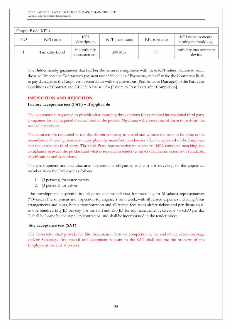
Output Based KPI's
NO KPI name KPI
description KPI [maximum] KPI tolerance
KPI measurement/ testing methodology
1 Turbidity Level the turbidity measurement
300 Max 99 turbidity measurement
device
The Bidder hereby guarantees that his/her Bid ensures compliance with these KPI values. Failure to reach
those will impact the Contractor’s payment under Schedule of Payments, and will make the Contractor liable
to pay damages to the Employer in accordance with the provisions [Performance Damages] to the Particular
Conditions of Contract and GCC Sub clause 12.4 [Failure to Pass Tests after Completion].
INSPECTION AND REJECTION
Factory acceptance test (FAT) – If applicable
The contractor is requested to provide after awarding three options for accredited international third party
companies for any required material used in the project; Miyahuna will choose one of them to perform the
needed inspections.
The contractor is requested to call the chosen company to attend and witness the tests to be done at the
manufacturer’s testing premises or any place the manufacturer chooses after the approval of the Employer
and the accredited third party. The third Party representative must ensure 100% complete matching and
compliance between the product and what is required in tender/contract documents in terms of standards,
specifications and conditions.
The pre-shipment and manufacturer inspection is obligatory and cost for travelling of the appointed
member from the Employer as follows
1. (3 persons) for water meters.
2. (3 persons) for valves.
“the pre‐shipment inspection is obligatory and the full cost for travelling for Miyahuna representatives
("Overseas Pre shipment and inspection for engineers for a week, with all related expenses including Visas
arrangements and costs, hotels transportation and all related fees taxes airfare tickets and per diems equal
to one hundred fifty JD per day for the staff and 250 JD for top management , director or CEO per day
") shall be borne by the supplier/contractor and shall be incorporated in the tender prices.
Site acceptance test (SAT)
The Contractor shall provide full Site Acceptance Tests on completion at the end of the execution stage
and/or Sub-stage. Any special test equipment relevant to the SAT shall become the property of the
Employer at the end of project.