Embed Size (px)
Citation preview

1 1
Presentación:
Líderes en la Gestión del Agua y Rentabilidad Ambiental
México, D.F. Septiembre – 25 , 2015

2
1. Introducción. 2. Normatividad & Pagos derechos
3. Bases Diseño. 4. Secuencias Tecnológicas. 5. Tendencias tecnológicas.
Buena calidad de agua
Menor consumo
Ahorro económico y menos contaminantes
México, D.F. Septiembre – 25 , 2015

3
¿Por que Cuidar y Reutilizar el Agua?
February 21, 2014 Footer text here México, D.F. Septiembre – 25 , 2015

4
Precipitación Media Anual en México
February 21, 2014 Footer text here
Puebla
Precipitación
Media Anual
< 1 270 mm
Semarnat,
2005|
México, D.F. Septiembre – 25 , 2015

5
Comisión Nacional del Agua Subdirección General Técnica
Ser la autoridad en materia de cantidad y calidad de las aguas nacionales.
Misión: “Administrar y preservar las aguas nacionales y sus bienes inherentes, con la corresponsabilidad de los tres órdenes de gobierno y la sociedad en general”.
Gerencia de Calidad del Agua Realizar el monitoreo sistemático de la
calidad del agua en los cuerpos de agua del país
Uso sostenible
Gestión del recurso en el territorio nacional
México, D.F. Septiembre – 25 , 2015

6 México, D.F. Septiembre – 25 , 2015

7 México, D.F. Septiembre – 25 , 2015

8
¿Qué son los factores que impiden un mejor desempeño del sector?
Agua y saneamiento para todos y para siempre
México, D.F. Septiembre – 25 , 2015

9
Estándares de Calidad del Agua
February 21, 2014 Footer text here
Indicador Normas Oficiales Mexicanas
001 002 003 127
B1*
C2*
Contacto
indirecto
Contacto
directo
DBO mg/l 75 30 150 30 20
SST
mg/l
75
40
125
30
20
NT
Nitratos
Nitritos
Amoniacal
mg/l
40
15
----------
10.55
10.00
0.05
0.50
PT mg/l 20 5
Coliformes
Fecales
Totales
NPM/1
00ml
---------
--
--------
---
----------
--
5
240
<2
No
Detectable
Huevos de
helminto
h/l
1000
1
SDT mg/l 1000
1 Uso
público
urbano 2
Protección
de vida
acuática
* Muestra
simple
promedio
México, D.F. Septiembre – 25 , 2015

10 February 21, 2014 Footer text here
CAPITULO VIII DERECHO POR USO O APROVECHAMIENTO DE BIENES DEL DOMINIO PÚBLICO DE LA NACIÓN COMO CUERPOS RECEPTORES DE LAS DESCARGAS DE AGUAS RESIDUALES
Artículo 223.-
Por la explotación, uso o aprovechamiento de aguas nacionales
a que se refiere este Capitulo, se pagara el derecho sobre agua,
de conformidad con la zona de disponibilidad de agua y la
cuenca o acuífero en que se efectué su extracción y de acuerdo
con las siguientes cuotas:
A. Por las aguas provenientes de fuentes superficiales o
extraídas del subsuelo por cada metro cubico:
México, D.F. Septiembre – 25 , 2015

11
• Art . 88 de la LAN.
DESCARGAS DE AGUAS RESIDUALES
PERMISO DE DESCARGA DE AGUAS RESIDUALES
CUERPOS RECEPTORES
SISTEMAS DE DRENAJE O
ALCANTARILLADOS
México, D.F. Septiembre – 25 , 2015

12
1.- Para los contribuyentes que no cuenten con ningún tipo de tratamiento en su agua residual , deberán pagar el volumen descargado por trimestre por la cuota según actividad y cuerpo receptor.
• Artículo 277-B. El monto del derecho a pagar se determinará aplicando al volumen descargado durante el trimestre las siguientes cuotas por cada metro cúbico, según corresponda:
DETERMINACIÓN DE PAGOS DE DERECHOS (CONAGUA)
CUOTA SEGÚN ACTIVIDAD Y CUERPO
RECEPTOR VOLUMEN
$ DEL DERECHO A
PAGAR
México, D.F. Septiembre – 25 , 2015

13
INTERRELACIONES ENTRE LAS FRACCIONES DE SÓLIDOS EN AGUA RESIDUAL
Muestra Evaporación Cono Imhoff ST SSed
Filtro Evaporación
del filtro
Evaporación del
filtrado
SDT SST
Horno Horno
SDV SSF
SFT SVT ST
SDF SSV
México, D.F. Septiembre – 25 , 2015

14
ANÁLISE DO FLUXO DE MATERIAIS (AFM)
• Ferramenta de apoio ao gerenciamento;
• Permite a avaliação dos fluxos de resíduos, bem como a identificação de suas fontes geradoras;
AFM
Lei de conservação da matéria
Insumos e subprodutos
do tratamento de esgoto
impactos negativos e
custos
• AFM em ETEs ainda é incipiente;
• Aplicação da AFM em uma ETE dotada de reatores anaeróbios e pós-tratamento com flotadores por ar dissolvido
México, D.F. Septiembre – 25 , 2015

15
RESULTADOS: AFM
México, D.F. Septiembre – 25 , 2015

16 México, D.F. Septiembre – 25 , 2015
PROCESOS DE TRATAMIENTO DE AGUAS INDUSTRIALES

17
TECNOLOGÍA. REVISIÓN & INNOVACIÓN
México, D.F. Septiembre – 25 , 2015

18 18
•Agua Industrial & Congénita y su
ciclo No convencional en la
producción de petróleo y gas de lutita.
(Shale)
•Cada etapa de este ciclo, requiere
de estándares, para su
dimensionamiento.
Problemática & Oportunidades
México, D.F. Septiembre – 25 , 2015

20
PLANTA DE TRATAMIENTO DE AGUAS RESIDUALES LODOS ACTIVADOS
México, D.F. Septiembre – 25 , 2015
21
Reutilización de aguas residuales para una planta de cogeneración.
Uso de filtros y UF
Membrana dual
Pre-tratamiento Coagulantes +
UF + RO
México, D.F. Septiembre – 25 , 2015
Deionización

22
FINE SCREENING
• Increase the operational stability of membrane-
activated sludge plants
(in particual hollow fibre membranes).
• Remove hairs, fibres and fine suspended
material.
• Reduce COD/BOD5 in river
and sea outfall applications.
• Remove overflowing activated sludge flocs from the secondary clarifier effluent.
• Allow to reduce AFS by 95%, COD/BOD5 by 65% and phosphorus by up to 60% through addition of precipitants and coagulants.
Innovative machines ....
México, D.F. Septiembre – 25 , 2015

23
Features of different screen and mesh shapes. Huber
wedge wire
e = 6 – 0.5 mm
High separation efficiency
High throughput capacity
square mesh
w = 1.0 – 0.2 mm
Maximum separation efficiency
due to the square mesh that
provides a defined separation size
The mesh separates up to 65% more screenings than
the wedge wire.
The wedge wire achieves a higher throughput. México, D.F. Septiembre – 25 , 2015
24 México, D.F. Septiembre – 25 , 2015
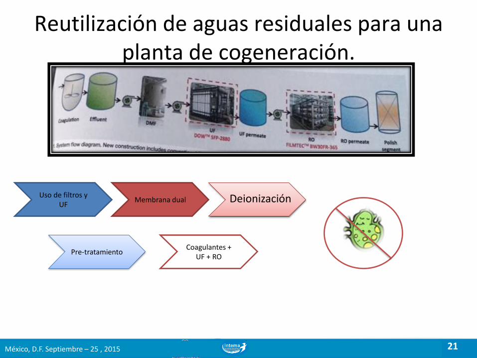
FILTRO CONTINUO ESPIRAL
Criba filtrante. 0.1 a .35 mm Rastra cepillo interno espiral Descarga continua filtrado & lodos espeso

25
REACTORES BIOLÓGICOS
Eficiencia
México, D.F. Septiembre – 25 , 2015

26
Material: HDPE (virgin or recycled)
Size: 12 mm
Surface area (effective): 650 m²/m³ of carriers
Geometry: Highly open external surface
MBBR PROCESS. INNOVATION THAT WORKS: AQWISE BIOMASS CARRIERS
México, D.F. Septiembre – 25 , 2015

27
Adequate wastewater treatment processes for industrial plants:
AGAR® Applications
DAF MBBR/FFAST DAF/
Clarifier Wastewater From plant
Treated effluent
Anaerobic
DAF MBBR/FFAST DAF/
Clarifier Wastewater From plant
Treated effluent
México, D.F. Septiembre – 25 , 2015

28 28
2. - Proceso UASB
La digestión anaerobia es un proceso de oxidación parcial de la
materia orgánica por bacterias en ausencia de oxígeno.
Proceso muy utilizado para tratar aguas residuales altamente cargadas en
DQO, por sus bajos costes de explotación:
Disminución importante de la potencia instalada en la planta
Producción de fangos entre 5 y 10 veces menor que los procesos aerobios
Y por sus ingresos:
Producción de electricidad y calor
Venta del fango granular
Tomas de
muestra
Drenaje Tuberías
alimentación Recirculación y mezcla
México, D.F. Septiembre – 25 , 2015

29 29
3. - Proceso UASB (Cont.)
Funcionamiento del proceso:
En el proceso UASB (Upflow Anaerobic Sludge Blanquet) el agua a tratar
es alimentada por la parte inferior del reactor por medio de un sistema de
distribución especialmente diseñado para facilitar un óptimo contacto entre
el influente y la biomasa.
El agua residual de entrada pasa a través de la capa granular de biomasa
del interior del reactor, mientras tiene lugar el proceso de conversión
biológica anaerobia de la DQO. Este proceso se desarrolla según
C6H12O6 3 CO2 + 3 CH4.
En la parte superior del reactor se separan, mediante un sistema de
decantadores-separadores lamelares , las tres fases formadas:
Agua, biogás y biomasa sólida.
México, D.F. Septiembre – 25 , 2015

30 30
6. Tratamiento fracción líquida: Eliminación del nitrógeno
30 ·
Proceso NAS®:
Hibrido fangos activos/Anammox, para eliminación del nitrógeno del
agua clarificada de salida del UASB o de la fracción líquida de la
digestión anaerobia de residuos orgánicos
Tecnología probada en el tratamiento de aguas residuales
industriales con baja relación C/N (Instalaciones operativas desde
2.004)
Nitrificación parcial a nitrito y desnitrificación en combinación con la
mutación autotrófica del amonio.
Resultado
Reducción de los costes energéticos en más del 60 %
No se necesita fuente de carbono externa
Se produce poco o nulo fango en exceso
México, D.F. Septiembre – 25 , 2015

31
PROCESOS SEPARACIÓN. FLUJO TRANSVERSAL EN LA MEMBRANA
.... .. . ..... .
..
.
.
.
......... . .
.....
..
..
.. .
.
.
..
........ . ....
.
.........
.
.
...
.
Filtered Water
México, D.F. Septiembre – 25 , 2015

32
¿QUE FILTRAN LOS MICRO & ULTRA FILTROS?
México, D.F. Septiembre – 25 , 2015

33 México, D.F. Septiembre – 25 , 2015

34
Elements Removed or Reduced with TMF Membrane Systems
Tubular Micro Filtration (TMF). Membranas Poliméricas & Cerámica
Regulated heavy metals (Cd, Cu, Cr, Ni, Pb, Zn.)
Arsenic (As)
Fluoride (F) removal
Removal of specific contaminants such as Ba, Mo, Fe, Al, Sn, Ra, phosphates (PO4), phosphorus (P), glass particles (Wafer and glass grinding)
Hardness removal (Ca, Mg)
Removal of dyes, pigments
Reduction of SO4 BOD5, COD, TOC
Pre treat for RO and increased recovery of RO with chemical softening
Removal of oil emulsion from water
México, D.F. Septiembre – 25 , 2015

35
Cooling Tower Blow Down
Location: Europe
• Flow rate: 450m3/h
• Operation date: April. 2005
• Application : Cooling tower blow-down
• TMF as pretreatment of RO
• System recover: 97% (ZLD)
México, D.F. Septiembre – 25 , 2015

36 México, D.F. Septiembre – 25 , 2015
Membranas Poliméricas. Fibra Hueca

37 México, D.F. Septiembre – 25 , 2015
38
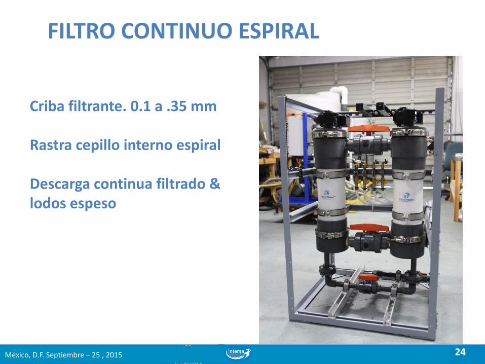
BIOLOGICAL TREATMENT EVOLUTION Conventional Activated SludgeTreatment
MBR treatment
Pre-Treatment Primary Clarifier Biological Reactor Secundary Clarifier
Thickener
Sand Filters & Desinfection
Dehidratation
system
Influent Effluent
Effluent
Pre-Treatment Biological Reactor Membrane Filtration System
Dehidratation
system
Influent
México, D.F. Septiembre – 25 , 2015

39
Membrane Technology
Membrane Technology | 2014 | www.berghof.com
RECOMMENDED MBR CONFIGURATION
Compact Screening System
If the influent has O&G
Homogenization Tank (if required)
BMT UF Unit
or
Sand & Coarse solids removal
Mixing system
DAF or Similar Hairs & Fibers removal (recommended discs filters 0,25 mm)
Fine Screening (If the influent has hairs and fibers)
Strainer protection (0,8 – 1,2 mm)
Permeate
Biological Reactor
México, D.F. Septiembre – 25 , 2015

40
ANMBR CONFIGURATIONS
México, D.F. Septiembre – 25 , 2015

41
MBR CONCEPTS
Permeate
Air
Feed
Submersible membranes
México, D.F. Septiembre – 25 , 2015

42
MBR CONCEPTS External membranes
México, D.F. Septiembre – 25 , 2015

43
PRINCIPLE OF SIDESTREAM INSIDE-OUT MEMBRANE FILTRATION
México, D.F. Septiembre – 25 , 2015

44
EXTERNAL VS SUBMERGED MBR TECHNOLOGY SUBMERGED MBR EXTERNAL MBR
BioAir DS Membrane FLAT SHEET HOLLOW FIBER TUBULAR
UF Air supply
Submerged 0.3 – 0.6 Nm³/h 0.3 – 0.8 Nm³/h
BioAir DS 0.1 – 0.2 Nm³/h
Average life time
Industrial 2 - 6 years
2 - 5 years
3 - 7 years
municpal 6 - 8 years
5 - 7 years
6 - 10 years
Average fluxrate
Industrial 5 -15 l/m².h 5 -15 l/m².h
20 - 40 l/m².h
municpal 15 - 30 l/m².h
15 - 30 l/m².h 30 - 60 l/m².h
Electrical consumption UF
0.2 – 0,5 kWh/m³
0.2 – 0,5 kWh/m³
0.2 – 0,5 kWh/m³
México, D.F. Septiembre – 25 , 2015

45
Module type MO 83G 37.03 I8
Membrane 8mm PES
Capacity 210 m³/h
Feed MLSS 15 - 20 g/l
14 loops
98 modules
Membrane surface 2646 m2
flux 80 l/m².h
Waste Water from Tannery
BERGHOF BioFlow
México, D.F. Septiembre – 25 , 2015

46 México, D.F. Septiembre – 25 , 2015
Small footprint

47
Adaptability in design configuration
Membrane Technology 47

48
II.1. Biogas desulphurization
What?
Why?
How?
H2S is a colorless, very poisonous, flammable gas with odor
With H2S content in biogas, SO2 and H2SO4 can be formed during combustion
SO2 and H2SO4 lead to heavy corrosion, increase the maintenance costs and
reduce the life time of the engines/boilers
H2S below 250 ppm commonly required by engine manufactories for full warranty
SOx emission limited by EU regulation
Iron sponge & activated carbon
Chemical scrubbler
Biological scrubbler
Regular media replacement
High chemical requirements
Operational cost !
High process efficiency
No solid disposal
No chemical requirement
Sustainable
Cost-effective
process !
www.colsen.nl México, D.F. Septiembre – 25 , 2015

49
II.2. About BIDOX®
= BIological biogas Desulphurization by OXidation BIDOX®
Air supply: oxygen
Temperature: 35-37°C
Packed media
Process conditions
Nutrients supply
Fresh water supply
H2S + 2O2 → SO42- + 2H+
www.colsen.nl México, D.F. Septiembre – 25 , 2015

50
• Una corriente eléctrica sacrifica
iones (Fe/Al) hacia la solución
• Contaminantes Disueltos y suspendidos reaccionan con los gases, iones y sus sub productos y precipitados/co-precipitados de la solución
Coagulación
Eléctrica
México, D.F. Septiembre – 25 , 2015

51
La Electrocoagulación es un proceso, que enlaza y combina campos de investigación por separado en un solo proceso.
Electrocoagulación combina:
electro-química + flotación + coagulación
Electrocoagulación de aguas residuales de crudo sintético usando ánodos de hierro, Lorgio V. Gonzales. , A. Gutierrez, G. Huaman, D. Veneu, A. Cardoso, and Mauricio Torem
Coagulación
Eléctrica
México, D.F. Septiembre – 25 , 2015

52
Coagulación Electrolisis
RLGRESSY
México, D.F. Septiembre – 25 , 2015

53
Modern society manufactures toxic organic chemicals – they
enter the environment – very difficult to remove
Organic chemicals in the environment
México, D.F. Septiembre – 25 , 2015

54
“Conventional” technologies – partially effective
Solids
Treated effluent
Wastewater treatment plants
Offgas
Ash Burn/Incinerate
Problem is “transferred” México, D.F. Septiembre – 25 , 2015

55
Secuencia de Procesos de Tratamientos. Remoción Orgánicos No Biodegradables
•Micro filtración (UF) •Osmosis inversa (RO) •Luz ultravioleta (UV) •Proceso de oxidación (AOP) •Ozono (O3)
World Water: Water Reuse & Desalination / 2015
México, D.F. Septiembre – 25 , 2015

56
Electro-oxidation – the “Holy Grail” since
the 1960s
Direct generation of hydroxyl radicals = no “limitations”
1987 – Boron Doped Diamond – BDD – Eureka!
México, D.F. Septiembre – 25 , 2015

57
AOP Performance
Fenton’s
Time
100%
Pollutant
reduction
0%
Ozone + ultraviolet
Ozone + hydrogen peroxide 50%
25%
75% Electro-Fenton’s
Electro-oxidation BDD eOx
México, D.F. Septiembre – 25 , 2015

58
• Limited recovery per
stage
• Fouling of lead
elements
• Scaling in low X-flow
zones 58
Conventional Reverse
Osmosis
México, D.F. Septiembre – 25 , 2015

59
The CCD Process
59 México, D.F. Septiembre – 25 , 2015

60
Membrane Performance
60
Conventional
Reverse
Osmosis
CCD
Reverse Osmosis
México, D.F. Septiembre – 25 , 2015

61 México, D.F. Septiembre – 25 , 2015
Altela. Proceso de Evaporación por Humidificación

62
ClearFlo. Oasys. Concentrador de Salmuera con Membrana (MBC) TM
México, D.F. Septiembre – 25 , 2015

63
Sin una visión compartida
example presentation title
Con una visión compartida
México, D.F. Septiembre – 25 , 2015
¿Como debemos actuar?

64
El Arte de un Buen Sistema de Tratamiento de Agua Industrial.
México, D.F. Septiembre – 25 , 2015

65 México, D.F. Septiembre – 25 , 2015
Muchas Gracias

66 México, D.F. Septiembre – 25 , 2015