Embed Size (px)
Citation preview
OPERATIONAL INSTRUCTION
IO-001
According to:
API 5 CT 9-th Editions, July 2011 / ISO 11960 Annex I. &
STATE ELABORATED VERIFIED APPROVED
CENTER OF RESPONSABILITY - CDR LAB MAC DIG
DATE 27.04.2012 30.04.2012 01.05.2012
SIGNATURE S. ASANDI I. TUTUNARU M. FRUGONI
PAGE 1/91
REV. 6
TENARIS TUBING (PRO-T, BSC-T) AND CASING (PRO-C, BSC-C)
PROTECTORS PERFORMANCE
TEST REPORT
values specified form customer requirements Standard.
Thread Protectors Requirements for Tenaris Threaded Products – TSH-PQ-00.0006 & PRD06693 * Note: if customer Specification values superior according to API, tested product performed with major
PERFORMANCE TEST REPORT FOR CASING AND TUBING TENARIS THREADED PROTECTORS

OPERATIONAL INSTRUCTION
IO-001 PERFORMANCE TEST REPORT FOR CASING AND
TUBING THREADED PROTECTORS
INDEX
Nr. Description Page
description 5
3.1 Impact Resistance (axial, angular and lateral) 5 3.2 Vibration Test 6 3.3 Stripping Test 7 3.4 Hookability Test 8 3.5 Corrosion Test 8 3.6 Chemical Resistance Test 8 3.7 Torque Test 9 3.8 Dimensional Stability Test 9 3.9 Environment / UV Resistance Test 9
4. Testing Results 10
PAGE 2/91
REV. 6
1. Product General 3 2. Test Specification – Table1 4 3. Acceptance criteria, formulas and employed equipment

OPERATIONAL INSTRUCTION
IO-001 PERFORMANCE TEST REPORT FOR CASING AND
TUBING THREADED PROTECTORS
API 5CT 9-th edition/ ISO 11960 ANNEX I &
DIAMETER NOTES TEMP. RANGE
All Identify all
samples -50ºF (-46ºC) to 150ºF
(66ºC)
TEST TEMPER TYPE
SPECIFIFIED TEST VALUE
DIM TEST CONDITIONS ACEPTANCE
CRITERIA
PRODUCT RANGE
<= 3 ½” 4- 6 5/8“ 7-8 5/8” 9-11” 11-14” >14”
AXIAL IMPACT
150ºF(66ºC) All
No damages or ovality in
the connection’s
thread and seal after the
impact
300 1200 1300 1890 2170 2920 FT/LB
Minimum free fall of the hitter 0,3m (12”)
/0,6m (24”) .Hitter steel bar of 38mm (1.5”) 70ºF (21ºC) All 300 1200 1300 1890 2170 2920 FT/LB
-50ºF(-46ºC) All 170 600 650 950 1090 1560 FT/LB
ANGULAR IMPACT
(45º)
150ºF(66ºC) All 160 600 780 1130 1300 1750 FT/LB
Place the protector and end size piece at 45º
from the horizontal. Minimum free fall of the hitter 0,3m (12”) / 0,6m (24”).Flat steel plate.
70ºF (21ºC) All 160 600 780 1130 1300 1750 FT/LB
-50ºF(-46ºC) All 85 300 300 570 650 880 FT/LB
LATERAL IMPACT 70ºF (21ºC) PIN 310 860 1560 2260 2600 3490 FT/LB Impact bar shall be oriented perpendicular to
the pipe axis
VIBRATION NA All Do not fall off or lose any torque
MIL STD 810, 900 RPM Minimum, 0.33”
Minimum vertical displacement, minimum acceleration of 4 time the gravity during
1,000,000 cycles
STRIPPING 150ºF(66ºC) 70ºF (21ºC) -50ºF(-46ºC)
PIN
No deformation
on the protectors
thread
60 x W 1000
60 x W 1700
60 x W 3100
60 x W 4500
60 x W 5200
60 x W 7000
LBS W= pipe mass, apply storage or thread
compounds, stabilize at given temperatures and perform the test.
HOOKABILITY NA All
No damages on the
connections thread and/or
seal
The protector manufacturer shall demonstrate that the connections suffer no damage during
handling.
CORROSION 95ºF(35ºC) All
No corrosion on the thread
and seal areas. Less than 10% corrosion
acceptable in the rest of the
connection
According to ASTM B 117. Apply storage or thread compounds, makeup at specified torque, the other end shall be closed with a ventilation hole. Perform the salt spray test for 1000 hours.
CHEMICAL RESISTANCE
NA All
No deformation or changes in
color, hardness and resistance.
Diesel, Acetone, Varsol, Storage and thread
compounds, Trichloroethylene, Paraffin, Shellsol D70, Hydrochl. Acid.
TORQUE 150ºF(66ºC) 70ºF (21ºC) -50ºF(-46ºC)
All
Meet the makeup and
brake out requirements. Damages on seal, loosing torque and
disengagement are
considered as rejects.
100 160 240 300 390 530 FT/LB
Apply storage or thread compounds, makeup the protector at specified torque and room
temperature, stabilize at each temperature and brake out the protector, compare the torque
result.
DIMENSIONAL STABILITY
150ºF(66ºC) 70ºF (21ºC) -50ºF(-46ºC)
All
Variations in thread
diameter shall be less than 50% of the connections thread height
Measure the diameter at room temperature, stabilize at each test temperature end record the diameter, stabilize again at room temperature
and record the diameter. Compare result.
ENVIRONMENT / UV RESISTANCE
NA All No damages. No changes
in color. Storage period:1 year
*Red color test conditions refer to specific customer qualification requirements greater comparing with API.
2. TABLE 1 - TEST SPECIFICATION
PAGE 4/91
REV. 6
TSH-PQ-00.0006 (rev.01) & upd. PRD06693

OPERATIONAL INSTRUCTION
IO-001 PERFORMANCE TEST REPORT FOR CASING AND
TUBING THREADED PROTECTORS
3. Acceptance criteria, formulas and employed equipment
description
Impact Resistance Test
The primary function of a thread protector for the pipe ends is to protect the threads and critical sealing areas from impact. This type of damage may occur at any point during the transportation and handling process. From the time the pipe leaves the threading facility until the time the pipe is run downhole at the rig floor, these critical areas must be adequately protected. Also the tests must be performed at three different environmental conditions -46°C, +21°C and + 66°C (-50ºF, 70ºF, 150ºF), that potentially could modify the characteristics of the protectors. For the tests it has been employed a guillotine that reproduces the energies described. Thread protectors shall be made-up on short pipe samples and tested at the loads specified in Table 1. The protectors will be screwed with recommended torque. Stabilize the made-up test pieces at the test temperature. Apply the load specified in Table1 using a minimum 60,1 cm. (24") free fall height. Protectors must withstand axial and angular impacts as specified Table 1 without damage to the machined surface of the Pin or the Box. Protectors will be considered acceptable provided the machined surface of the threaded connections specimens are not damaged or deformed (ovality phenomena).
Axial Impact
The surface impact will be a bar steel with 38 mm of diameter. The protectors must avoid
damages at the machined surface of the joint in three different environmental conditions -46°C, +21°C and + 66°C. During the axial impact the 38mm (1,5”) bar hit the protector in the centre of its axe as described in the following picture. Fig.1
Protectors
Steel bar
Pipe or coupling
PAGE 5/91
REV. 6
OPERATIONAL INSTRUCTION
IO-001 PERFORMANCE TEST REPORT FOR CASING AND
TUBING THREADED PROTECTORS
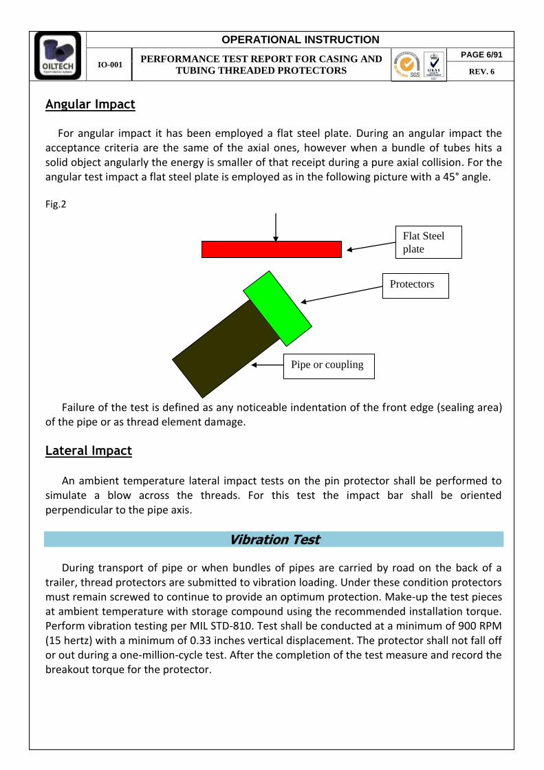
Angular Impact
For angular impact it has been employed a flat steel plate. During an angular impact the
acceptance criteria are the same of the axial ones, however when a bundle of tubes hits a solid object angularly the energy is smaller of that receipt during a pure axial collision. For the angular test impact a flat steel plate is employed as in the following picture with a 45° angle. Fig.2
Failure of the test is defined as any noticeable indentation of the front edge (sealing area)
of the pipe or as thread element damage.
Lateral Impact
An ambient temperature lateral impact tests on the pin protector shall be performed to
simulate a blow across the threads. For this test the impact bar shall be oriented perpendicular to the pipe axis.
Vibration Test
During transport of pipe or when bundles of pipes are carried by road on the back of a trailer, thread protectors are submitted to vibration loading. Under these condition protectors must remain screwed to continue to provide an optimum protection. Make-up the test pieces at ambient temperature with storage compound using the recommended installation torque. Perform vibration testing per MIL STD-810. Test shall be conducted at a minimum of 900 RPM (15 hertz) with a minimum of 0.33 inches vertical displacement. The protector shall not fall off or out during a one-million-cycle test. After the completion of the test measure and record the breakout torque for the protector.
Protectors
Flat Steel plate
Pipe or coupling
PAGE 6/91
REV. 6
OPERATIONAL INSTRUCTION
IO-001 PERFORMANCE TEST REPORT FOR CASING AND
TUBING THREADED PROTECTORS
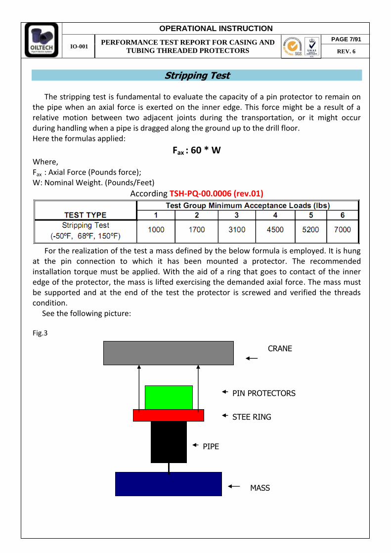
Stripping Test
The stripping test is fundamental to evaluate the capacity of a pin protector to remain on
the pipe when an axial force is exerted on the inner edge. This force might be a result of a relative motion between two adjacent joints during the transportation, or it might occur during handling when a pipe is dragged along the ground up to the drill floor. Here the formulas applied:
Fax : 60 * W Where, Fax : Axial Force (Pounds force); W: Nominal Weight. (Pounds/Feet)
According TSH-PQ-00.0006 (rev.01)
For the realization of the test a mass defined by the below formula is employed. It is hung
at the pin connection to which it has been mounted a protector. The recommended installation torque must be applied. With the aid of a ring that goes to contact of the inner edge of the protector, the mass is lifted exercising the demanded axial force. The mass must be supported and at the end of the test the protector is screwed and verified the threads condition. See the following picture: Fig.3
PIPE
PIN PROTECTORS
STEE RING
MASS
CRANE
PAGE 7/91
REV. 6

OPERATIONAL INSTRUCTION
IO-001 PERFORMANCE TEST REPORT FOR CASING AND
TUBING THREADED PROTECTORS
Hookability (Liftability) Test
For protectors designated as liftable, a test shall be conducted to confirm the suitability of
the protector in lifting applications. The test set-up is at the discretion of the manufacturer, but must be approved by customer. Two separate test shall be performed using the same load, but at different angles to represent different types of rigging set-ups.
For the first test load the lifting wire shall apply the load in a direction approximately perpendicular to the axis of the pipe sample.
For the second test load the lifting wire shall apply a load in a direction approximately 20° from the axis of the pipe. The test load shall be calculated as follows:
L (load, lbs) = 1.5 * 45 (ft) * W (lbs/ft)
Make-up the test pieces at ambient temperature with storage compound using the recommended torque. Apply the load and hold for 5 minutes. Remove the load and inspect the connection for damage. The type of hook, loads and test set-up shall be documented.
Corrosion Test
A protector should be able to prevent water penetration along threaded area in order to
prevent potential corrosive attack of threads and seals.
Make-up the test pieces at ambient temperature with storage compound using the recommended torque. The cut-off end of the connector shall be sealed and vented to allow circulation, or a pin by box test sample may be used. A salt spray test per ASTM B117 shall be conducted for as minimum of 1000 hours at + 35°C (95°F). The test piece shall be oriented in the test chamber to simulate pipe rack storage. At the completion of the test remove the sample and inspect for corrosion. Seal surfaces shall have no corrosion damage. Other areas of the connection shall have less than 10% damage on the external surfaces of pin connections and the internal surfaces of box connections. Record the storage compound used and provide photographs of any corrosion areas.
Chemical Resistance Test
PE protectors must be compatible with the chemical agents usually employed to clean joints. For the test we have fulfilled a 3 ½” tubing protector in the chemical agents, list here under, at 50° temperature for 24 hours. A diameter’s variation bigger than 10% and a hardness advanced 10 grades (Shore D) determine the failure of the test. LIST OF CHEMICAL AGENTS EMPLOYED
Trichloroethylene
Diesel
Paraffin
Acetone
PAGE 8/91
REV. 6

OPERATIONAL INSTRUCTION
IO-001 PERFORMANCE TEST REPORT FOR CASING AND
TUBING THREADED PROTECTORS
Shellsol D70
Varsol
Hydrochloric acid
Torque Test
The purpose of this test is to determine how the protector reacts to temperature changes and excessive make-up torque. Protectors which are damaged during make-up will be more susceptible to loosen or falloff during transportation and handling. Temperature changes can affect the fit of the protector.
To evaluate the torque stripping resistance of the thread protector during make-up, and attempt should be made to "strip-out" the pin and box protector.
The required "strip-out" torque must meet or exceed the torque limits specified below:
Make-up Torque Test – Recommended screwing Torque
Connection OD Torque 3 ½ " and less 100 ft-lbs
Above 3 ½ " to 6 5/8 " 160 ft-lbs
Above 6 5/8 " to 9 " 240 ft-lbs
Above 9" to 11 " 300 ft-lbs
Above 11 " to 14 " 390 ft-lbs
Above 14 " 530 ft-lbs
To evaluate the effects of temperature, make-up the sample using storage compound using the manufacturer's recommended practice and torque. Record the temperature and the torque used for make-up. Stabilize the samples at -50°F, 68°F and 150°F and breakout the protector recording the torque. Torque values shall not be greater than 135% or less than 65% of the make-up torque.
Dimensional Stability Test
Measure and record the thread diameters on the protector at 21°C (70°F). Stabilize the samples at -46°C (-50°F), and 66°C (150°F) and immediately measure and record the thread diameters. Re-stabilize the samples at 21°C (70°F) measure and record dates again. Changes in thread diameter resulting in thread engagement of less than one-half the specified thread height per side shall be unacceptable throughout the design temperature range.
Environment / UV Resistance Test
The purpose of this test is to determine how the protector responds to environment changes and UV protector resistance. It is sufficient one test sample of each used color master or paint. Test period for protector storage must be at least one year. No protector damages, paint detaching or color changes are accepted.
PAGE 9/91
REV. 6
OPERATIONAL INSTRUCTION
IO-001 PERFORMANCE TEST REPORT FOR CASING AND
TUBING THREADED PROTECTORS
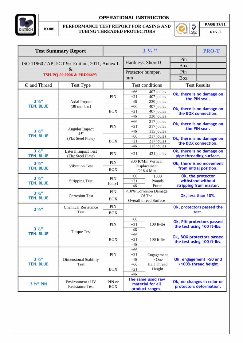
Test Summary Report 3 ½ ” PRO-T
ISO 11960 / API 5CT 9th Edition, 2011, Annex I. &
Hardness, ShoreD Pin Box
Protector bumper, mm
Pin Box
Ø and Thread Test Type Test conditions Test Results
3 ½” TEN. BLUE
Axial Impact (38 mm bar)
PIN +66 407 joules
Ok, there is no damage on the PIN seal.
+21 407 joules -46 230 joules
BOX +66 407 joules
Ok, there is no damage on the BOX connection.
+21 407 joules -46 230 joules
3 ½” TEN. BLUE
Angular Impact 45º
(Flat Steel Plate)
PIN +66 217 joules
Ok, there is no damage on the PIN seal.
+21 217 joules -46 115 joules
BOX +66 217 joules
Ok, there is no damage on the BOX connection.
+21 217 joules -46 115 joules
3 ½” TEN. BLUE
Lateral Impact Test (Flat Steel Plate)
PIN +21 421 joules Ok, there is no damage on
pipe threading surface.
3 ½” TEN. BLUE Vibration Test
PIN 900 R/Min Vertical Displacement
Of 8.4 Mm
Ok, there is no movement from initial position. BOX
3 ½” TEN. BLUE Stripping Test
PIN (only)
+66 1000 Pounds Force
Ok, the protector withstand without
stripping from master. +21 -46
3 ½” TEN. BLUE Corrosion Test
PIN <10% Corrosion Damage Of The
Overall thread Surface Ok, less than 10%.
BOX
3 ½” Chemical Resistance Test
PIN
Ok, protectors passed the test. BOX
3 ½” TEN. BLUE Torque Test
PIN +66
100 ft-lbs Ok, PIN protectors passed the test using 100 ft-lbs.
+21 -46
BOX +66
100 ft-lbs Ok, BOX protectors passed the test using 100 ft-lbs.
+21 -46
3 ½” TEN. BLUE
Dimensional Stability Test
PIN +66
Engagement > One
Half Thread Height
Ok, engagement >50 and <100% thread height
+21 -46
BOX +66 +21 -46
3 ½” PIN Environment / UV Resistance Test
PIN or BOX
The same used raw material for all product ranges.
Ok, no changes in color or protectors deformation.
PAGE 17/91
REV. 6
TSH-PQ-00.0006 & PRD06693
OPERATIONAL INSTRUCTION
IO-001 PERFORMANCE TEST REPORT FOR CASING AND
TUBING THREADED PROTECTORS
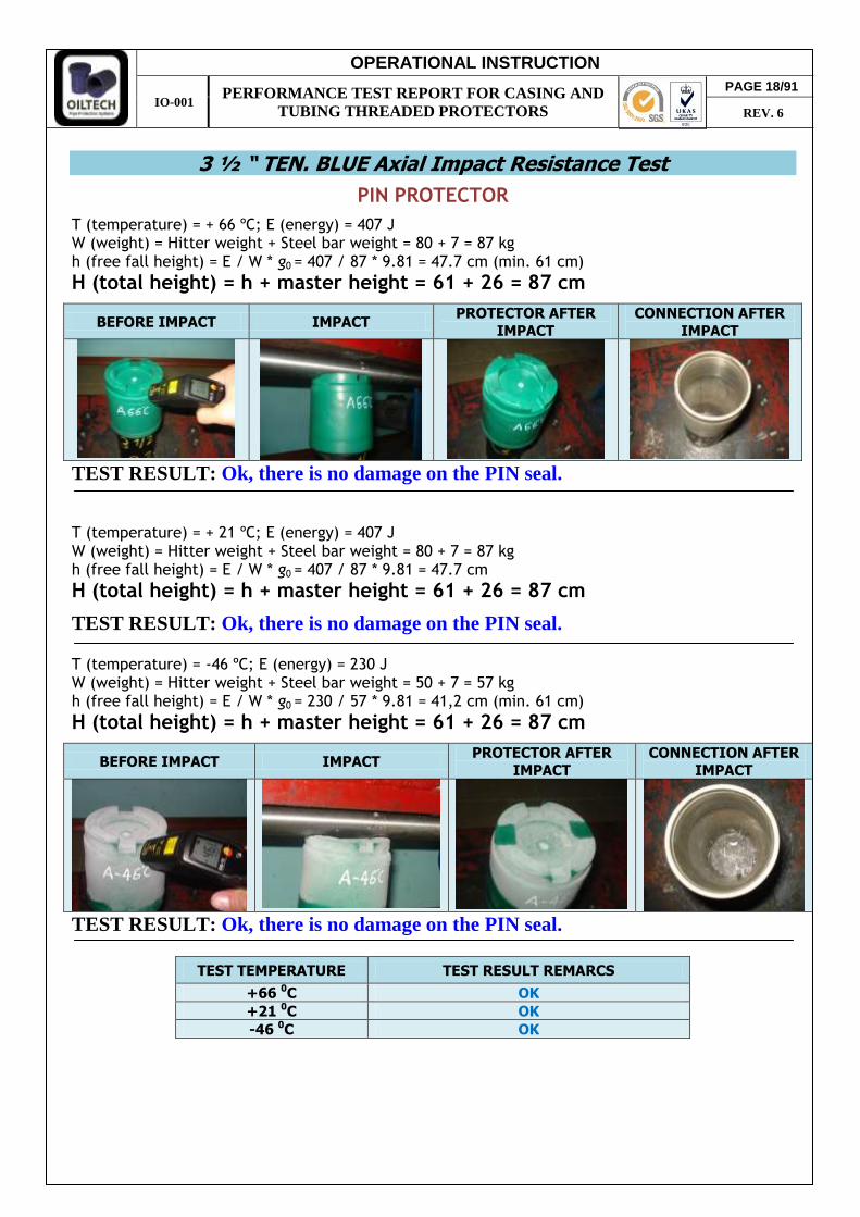
3 ½ “ TEN. BLUE Axial Impact Resistance Test
PIN PROTECTOR
T (temperature) = + 66 ºC; E (energy) = 407 J W (weight) = Hitter weight + Steel bar weight = 80 + 7 = 87 kg h (free fall height) = E / W * g0 = 407 / 87 * 9.81 = 47.7 cm (min. 61 cm)
H (total height) = h + master height = 61 + 26 = 87 cm
BEFORE IMPACT IMPACT PROTECTOR AFTER
IMPACT
CONNECTION AFTER
IMPACT
TEST RESULT: Ok, there is no damage on the PIN seal. T (temperature) = + 21 ºC; E (energy) = 407 J W (weight) = Hitter weight + Steel bar weight = 80 + 7 = 87 kg h (free fall height) = E / W * g0 = 407 / 87 * 9.81 = 47.7 cm
H (total height) = h + master height = 61 + 26 = 87 cm
TEST RESULT: Ok, there is no damage on the PIN seal. T (temperature) = -46 ºC; E (energy) = 230 J W (weight) = Hitter weight + Steel bar weight = 50 + 7 = 57 kg h (free fall height) = E / W * g0 = 230 / 57 * 9.81 = 41,2 cm (min. 61 cm)
H (total height) = h + master height = 61 + 26 = 87 cm
BEFORE IMPACT IMPACT PROTECTOR AFTER
IMPACT
CONNECTION AFTER
IMPACT
TEST RESULT: Ok, there is no damage on the PIN seal.
TEST TEMPERATURE TEST RESULT REMARCS
+66 0C OK +21 0C OK -46 0C OK
PAGE 18/91
REV. 6
OPERATIONAL INSTRUCTION
IO-001 PERFORMANCE TEST REPORT FOR CASING AND
TUBING THREADED PROTECTORS
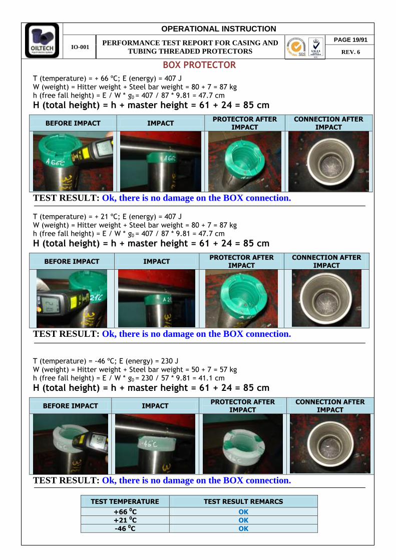
BOX PROTECTOR
T (temperature) = + 66 ºC; E (energy) = 407 J W (weight) = Hitter weight + Steel bar weight = 80 + 7 = 87 kg h (free fall height) = E / W * g0 = 407 / 87 * 9.81 = 47.7 cm
H (total height) = h + master height = 61 + 24 = 85 cm
BEFORE IMPACT IMPACT PROTECTOR AFTER
IMPACT
CONNECTION AFTER
IMPACT
TEST RESULT: Ok, there is no damage on the BOX connection. T (temperature) = + 21 ºC; E (energy) = 407 J W (weight) = Hitter weight + Steel bar weight = 80 + 7 = 87 kg h (free fall height) = E / W * g0 = 407 / 87 * 9.81 = 47.7 cm
H (total height) = h + master height = 61 + 24 = 85 cm
BEFORE IMPACT IMPACT PROTECTOR AFTER
IMPACT CONNECTION AFTER
IMPACT
TEST RESULT: Ok, there is no damage on the BOX connection. T (temperature) = -46 ºC; E (energy) = 230 J W (weight) = Hitter weight + Steel bar weight = 50 + 7 = 57 kg h (free fall height) = E / W * g0 = 230 / 57 * 9.81 = 41.1 cm
H (total height) = h + master height = 61 + 24 = 85 cm
BEFORE IMPACT IMPACT PROTECTOR AFTER
IMPACT CONNECTION AFTER
IMPACT
TEST RESULT: Ok, there is no damage on the BOX connection.
TEST TEMPERATURE TEST RESULT REMARCS
+66 0C OK +21 0C OK -46 0C OK
PAGE 19/91
REV. 6

OPERATIONAL INSTRUCTION
IO-001 PERFORMANCE TEST REPORT FOR CASING AND
TUBING THREADED PROTECTORS
3 ½ “ TEN. BLUE Angular Impact Resistance Test
PIN PROTECTOR
T (temperature) = + 66 ºC; E (energy) = 217 J W (weight) = Hitter weight = 40 kg h (free fall height) = E / W * g0 = 217 / 40 * 9.81 = 55,3 cm (min. 61 cm)
H (total height) = h + master height = 61 + 27,3 = 88,3 cm
BEFORE IMPACT IMPACT PROTECTOR AFTER
IMPACT
CONNECTION AFTER
IMPACT
TEST RESULT: Ok, there is no damage on the PIN seal. T (temperature) = + 21 ºC; E (energy) = 217 J W (weight) = Hitter weight = 40 kg h (free fall height) = E / W * g0 = 217 / 40 * 9.81 = 55,3 cm (min. 61 cm)
H (total height) = h + master height = 61 + 27,3 = 88,3 cm
BEFORE IMPACT IMPACT PROTECTOR AFTER
IMPACT
CONNECTION AFTER
IMPACT
TEST RESULT: Ok, there is no damage on the PIN seal. T (temperature) = -46 ºC; E (energy) = 115 J W (weight) = Hitter weight = 20 kg h (free fall height) = E / W * g0 = 115 / 20 * 9.81 = 58,6 (min. 61 cm)
H (total height) = h + master height = 61 + 27,3 = 88,3 cm
BEFORE IMPACT IMPACT PROTECTOR AFTER
IMPACT CONNECTION AFTER
IMPACT
TEST RESULT: Ok, there is no damage on the PIN seal.
TEST TEMPERATURE TEST RESULT REMARCS
+66 0C OK +21 0C OK -46 0C OK
PAGE 20/91
REV. 6
OPERATIONAL INSTRUCTION
IO-001 PERFORMANCE TEST REPORT FOR CASING AND
TUBING THREADED PROTECTORS
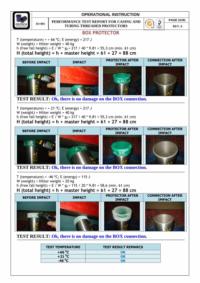
BOX PROTECTOR
T (temperature) = + 66 ºC; E (energy) = 217 J W (weight) = Hitter weight = 40 kg h (free fall height) = E / W * g0 = 217 / 40 * 9.81 = 55,3 cm (min. 61 cm)
H (total height) = h + master height = 61 + 27 = 88 cm
BEFORE IMPACT IMPACT PROTECTOR AFTER
IMPACT
CONNECTION AFTER
IMPACT
TEST RESULT: Ok, there is no damage on the BOX connection. T (temperature) = + 21 ºC; E (energy) = 217 J W (weight) = Hitter weight = 40 kg h (free fall height) = E / W * g0 = 217 / 40 * 9.81 = 55,3 cm (min. 61 cm)
H (total height) = h + master height = 61 + 27 = 88 cm
BEFORE IMPACT IMPACT PROTECTOR AFTER
IMPACT CONNECTION AFTER
IMPACT
TEST RESULT: Ok, there is no damage on the BOX connection. T (temperature) = -46 ºC; E (energy) = 115 J W (weight) = Hitter weight = 20 kg h (free fall height) = E / W * g0 = 115 / 20 * 9.81 = 58,6 (min. 61 cm)
H (total height) = h + master height = 61 + 27 = 88 cm
BEFORE IMPACT IMPACT PROTECTOR AFTER
IMPACT
CONNECTION AFTER
IMPACT
TEST RESULT: Ok, there is no damage on the BOX connection.
TEST TEMPERATURE TEST RESULT REMARCS
+66 0C OK +21 0C OK -46 0C OK
PAGE 21/91
REV. 6

OPERATIONAL INSTRUCTION
IO-001 PERFORMANCE TEST REPORT FOR CASING AND
TUBING THREADED PROTECTORS
3 ½ “TEN. BLUE Lateral Impact Resistance Test
PIN PROTECTOR
T (temperature) = + 21 ºC; E (energy) = 421 J W (weight) = Hitter weight = 80 kg h (free fall height) = E / W * g0 = 421 / 80 * 9.81 = 53,6 cm (min. 61 cm)
H (total height) = h + master height = 61 + 12,2 = 73,2 cm
TEST RESULT: Ok, there is no damage on master thread area. TEST TEMPERATURE TEST RESULT REMARCS
+21 0C OK
Vibration Test PRODUCT: 3 ½” TEN. BLUE PROTECTOR
INITIAL TEST CONDITIONS
Samples were inspected and prepared following the API specifications according to MIL-TD-810 norm.
CONDITION AFTRE TEST
PAGE 22/91
REV. 6

OPERATIONAL INSTRUCTION
IO-001 PERFORMANCE TEST REPORT FOR CASING AND
TUBING THREADED PROTECTORS
RESULTS:
Stripping Test
PRODUCT: 3 ½ ” TEN. BLUE PIN PROTECTOR
Fax (API)= 60 x W Where: F = Axial force (pounds force); Fax (requested according TSH-PQ-00.0006 procedure) = 1000 lbs The protector during the test has supported the load. It has been screwed and the thread profile has remained unchanged.
Corrosion Test
PRODUCT: 3 ½” TEN. BLUE PROTECTOR
Made according ASTM B117. BOX and PIN are screwed on masters with recommended
torque. PIN is placed in vertical position, BOX protector with an angle of almost 450. Every hour salt water circulates simulating a heavy rain. Room temperature is maintained 33-370C. Performing test during 40 consecutive days (1000 hours).
Passed the period previewed, a slight water presence has been found to the inside of Pin protector less than 10%, while no water or corrosion phenomena has been noticed inside the box connection, due to the particular shape of the coupling (TEN. BLUE) that provides a greater protection.
The protectors have surpassed the tests.
PAGE 23/91
REV. 6
OPERATIONAL INSTRUCTION
IO-001 PERFORMANCE TEST REPORT FOR CASING AND
TUBING THREADED PROTECTORS
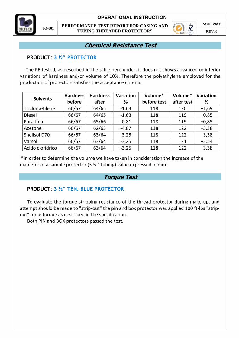
Chemical Resistance Test
PRODUCT: 3 ½” PROTECTOR
The PE tested, as described in the table here under, it does not shows advanced or inferior variations of hardness and/or volume of 10%. Therefore the polyethylene employed for the production of protectors satisfies the acceptance criteria.
Solvents Hardness
before Hardness
after Variation
% Volume*
before test Volume* after test
Variation %
Tricloroetilene 66/67 64/65 -1,63 118 120 +1,69
Diesel 66/67 64/65 -1,63 118 119 +0,85
Paraffina 66/67 65/66 -0,81 118 119 +0,85
Acetone 66/67 62/63 -4,87 118 122 +3,38
Shellsol D70 66/67 63/64 -3,25 118 122 +3,38
Varsol 66/67 63/64 -3,25 118 121 +2,54
Acido cloridrico 66/67 63/64 -3,25 118 122 +3,38
*In order to determine the volume we have taken in consideration the increase of the diameter of a sample protector (3 ½ " tubing) value expressed in mm.
Torque Test
PRODUCT: 3 ½” TEN. BLUE PROTECTOR
To evaluate the torque stripping resistance of the thread protector during make-up, and
attempt should be made to "strip-out" the pin and box protector was applied 100 ft-lbs "strip-out" force torque as described in the specification.
Both PIN and BOX protectors passed the test.
PAGE 24/91
REV. 6

OPERATIONAL INSTRUCTION
IO-001 PERFORMANCE TEST REPORT FOR CASING AND
TUBING THREADED PROTECTORS
Test Summary Report 5 ½ " PRO-T&C
ISO 11960 / API-5CT 9th Edition, 2011, Annex I. &
Hardness, ShoreD Pin Box
Protector bumper, mm
Pin Box
Ø and Thread Test Type Test conditions Test Results
5 ½” TSH 521
Axial Impact (38 mm bar)
PIN +66 1628 joules
Ok, there is no damage on the PIN seal.
+21 1628 joules -46 814 joules
BOX +66 1628 joules
Ok, there is no damage on the BOX connection.
+21 1628 joules -46 814 joules
5 ½” TSH 521
Angular Impact 45º
(Flat Steel Plate)
PIN +66 814 joules
Ok, there is no damage on the PIN seal.
+21 814 joules -46 407 joules
BOX +66 814 joules
Ok, there is no damage on the BOX connection.
+21 814 joules -46 407 joules
5 ½” TSH 521
Lateral Impact Test (Flat Steel Plate)
PIN +21 1167 joules Ok, there is no damage
on pipe threading surface.
PAGE 25/91
REV. 6
TSH-PQ-00.0006 & PRD06693

OPERATIONAL INSTRUCTION
IO-001 PERFORMANCE TEST REPORT FOR CASING AND
TUBING THREADED PROTECTORS
5 ½ “ TSH 521 Axial Impact Resistance Test
PIN PROTECTOR
T (temperature) = + 66 ºC; E (energy) = 1628 J W (weight) = Hitter weight + Steel bar weight = 220 + 7 = 227 kg h (free fall height) = E / W * g0 = 1628 / 227 * 9.81 = 73,1 cm
H (total height) = h + master height = 73,1 + 37 = 110,1 cm
BEFORE IMPACT IMPACT PROTECTOR AFTER
IMPACT
CONNECTION AFTER
IMPACT
TEST RESULT: Ok, there is no damage on the PIN seal. T (temperature) = + 21 ºC; E (energy) = 1628 J W (weight) = Hitter weight + Steel bar weight = 220 + 7 = 227 kg h (free fall height) = E / W * g0 = 1628 / 227 * 9.81 = 73,1 cm
H (total height) = h + master height = 73,1 + 37 = 110,1 cm
TEST RESULT: Ok, there is no damage on the PIN seal. T (temperature) = -46 ºC; E (energy) = 814 J W (weight) = Hitter weight + Steel bar weight = 80 + 7 = 87 kg h (free fall height) = E / W * g0 = 814 / 87 * 9.81 = 95,4
H (total height) = h + master height = 95,4 + 37 = 132,4 cm
BEFORE IMPACT IMPACT PROTECTOR AFTER
IMPACT
CONNECTION AFTER
IMPACT
TEST RESULT: Ok, there is no damage on the PIN seal.
TEST TEMPERATURE TEST RESULT REMARCS
+66 0C OK +21 0C OK -46 0C OK
PAGE 26/91
REV. 6

OPERATIONAL INSTRUCTION
IO-001 PERFORMANCE TEST REPORT FOR CASING AND
TUBING THREADED PROTECTORS
BOX PROTECTOR
T (temperature) = + 66 ºC; E (energy) = 1628 J W (weight) = Hitter weight + Steel bar weight = 220 + 7 = 227 kg h (free fall height) = E / W * g0 = 1628 / 227 * 9.81 = 73,1 cm
H (total height) = h + master height = 73,1 + 35 = 108,1 cm
BEFORE IMPACT IMPACT PROTECTOR AFTER
IMPACT
CONNECTION AFTER
IMPACT
TEST RESULT: Ok, there is no damage on the BOX connection. T (temperature) = + 21 ºC; E (energy) = 1628 J W (weight) = Hitter weight + Steel bar weight = 220 + 7 = 227 kg h (free fall height) = E / W * g0 = 1628 / 227 * 9.81 = 73,1 cm
H (total height) = h + master height = 73,1 + 35 = 108,1 cm
BEFORE IMPACT IMPACT PROTECTOR AFTER
IMPACT
CONNECTION AFTER
IMPACT
TEST RESULT: Ok, there is no damage on the BOX connection. T (temperature) = -46 ºC; E (energy) = 814 J W (weight) = Hitter weight + Steel bar weight = 80 + 7 = 87 kg h (free fall height) = E / W * g0 = 814 / 87 * 9.81 = 95,4
H (total height) = h + master height = 94,5 + 35 = 129,5 cm
BEFORE IMPACT IMPACT PROTECTOR AFTER
IMPACT
CONNECTION AFTER
IMPACT
TEST RESULT: Ok, there is no damage on the BOX connection.
TEST TEMPERATURE TEST RESULT REMARCS
+66 0C OK +21 0C OK -46 0C OK
PAGE 27/91
REV. 6
OPERATIONAL INSTRUCTION
IO-001 PERFORMANCE TEST REPORT FOR CASING AND
TUBING THREADED PROTECTORS
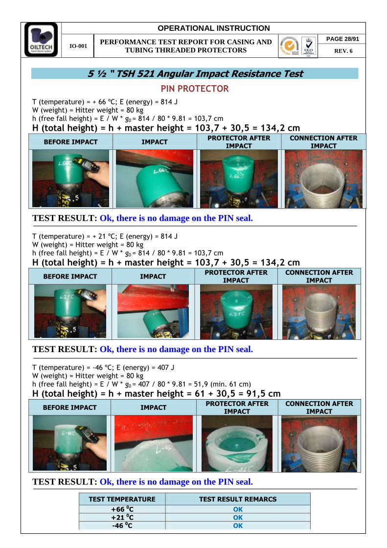
5 ½ “ TSH 521 Angular Impact Resistance Test
PIN PROTECTOR
T (temperature) = + 66 ºC; E (energy) = 814 J W (weight) = Hitter weight = 80 kg h (free fall height) = E / W * g0 = 814 / 80 * 9.81 = 103,7 cm
H (total height) = h + master height = 103,7 + 30,5 = 134,2 cm
BEFORE IMPACT IMPACT PROTECTOR AFTER
IMPACT
CONNECTION AFTER
IMPACT
TEST RESULT: Ok, there is no damage on the PIN seal. T (temperature) = + 21 ºC; E (energy) = 814 J W (weight) = Hitter weight = 80 kg h (free fall height) = E / W * g0 = 814 / 80 * 9.81 = 103,7 cm
H (total height) = h + master height = 103,7 + 30,5 = 134,2 cm
BEFORE IMPACT IMPACT PROTECTOR AFTER
IMPACT
CONNECTION AFTER
IMPACT
TEST RESULT: Ok, there is no damage on the PIN seal. T (temperature) = -46 ºC; E (energy) = 407 J W (weight) = Hitter weight = 80 kg h (free fall height) = E / W * g0 = 407 / 80 * 9.81 = 51,9 (min. 61 cm)
H (total height) = h + master height = 61 + 30,5 = 91,5 cm
BEFORE IMPACT IMPACT PROTECTOR AFTER
IMPACT CONNECTION AFTER
IMPACT
TEST RESULT: Ok, there is no damage on the PIN seal.
TEST TEMPERATURE TEST RESULT REMARCS
+66 0C OK +21 0C OK -46 0C OK
PAGE 28/91
REV. 6
OPERATIONAL INSTRUCTION
IO-001 PERFORMANCE TEST REPORT FOR CASING AND
TUBING THREADED PROTECTORS
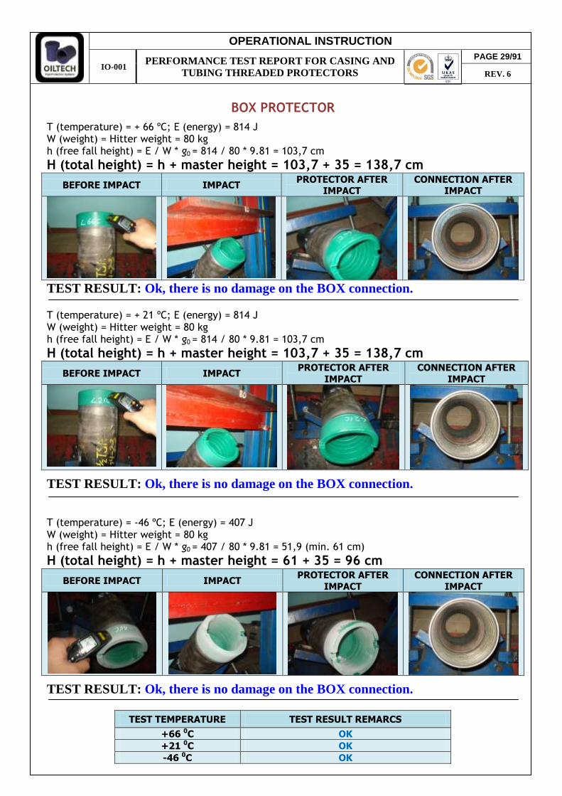
BOX PROTECTOR
T (temperature) = + 66 ºC; E (energy) = 814 J W (weight) = Hitter weight = 80 kg h (free fall height) = E / W * g0 = 814 / 80 * 9.81 = 103,7 cm
H (total height) = h + master height = 103,7 + 35 = 138,7 cm
BEFORE IMPACT IMPACT PROTECTOR AFTER
IMPACT CONNECTION AFTER
IMPACT
TEST RESULT: Ok, there is no damage on the BOX connection. T (temperature) = + 21 ºC; E (energy) = 814 J W (weight) = Hitter weight = 80 kg h (free fall height) = E / W * g0 = 814 / 80 * 9.81 = 103,7 cm
H (total height) = h + master height = 103,7 + 35 = 138,7 cm
BEFORE IMPACT IMPACT PROTECTOR AFTER
IMPACT
CONNECTION AFTER
IMPACT
TEST RESULT: Ok, there is no damage on the BOX connection. T (temperature) = -46 ºC; E (energy) = 407 J W (weight) = Hitter weight = 80 kg h (free fall height) = E / W * g0 = 407 / 80 * 9.81 = 51,9 (min. 61 cm)
H (total height) = h + master height = 61 + 35 = 96 cm
BEFORE IMPACT IMPACT PROTECTOR AFTER
IMPACT
CONNECTION AFTER
IMPACT
TEST RESULT: Ok, there is no damage on the BOX connection.
TEST TEMPERATURE TEST RESULT REMARCS
+66 0C OK +21 0C OK -46 0C OK
PAGE 29/91
REV. 6

OPERATIONAL INSTRUCTION
IO-001 PERFORMANCE TEST REPORT FOR CASING AND
TUBING THREADED PROTECTORS
5 ½ “ TSH 521 Lateral Impact Resistance Test
PIN PROTECTOR
T (temperature) = + 21 ºC; E (energy) = 1167 J W (weight) = Hitter weight = 164 kg h (free fall height) = E / W * g0 = 1167 / 164 * 9.81 = 72,5 cm
H (total height) = h + master height = 72,5 + 18 = 90,5 cm BEFORE IMPACT IMPACT
PROTECTOR AFTER IMPACT CONNECTION AFTER
IMPACT
TEST RESULT: Ok, there is no damage or ovality on master thread area.
TEST TEMPERATURE TEST RESULT REMARCS
+21 0C OK
PAGE 30/91
REV. 6

OPERATIONAL INSTRUCTION
IO-001 PERFORMANCE TEST REPORT FOR CASING AND
TUBING THREADED PROTECTORS
PAGE 31/91
REV. 6
OPERATIONAL INSTRUCTION
IO-001 PERFORMANCE TEST REPORT FOR CASING AND
TUBING THREADED PROTECTORS
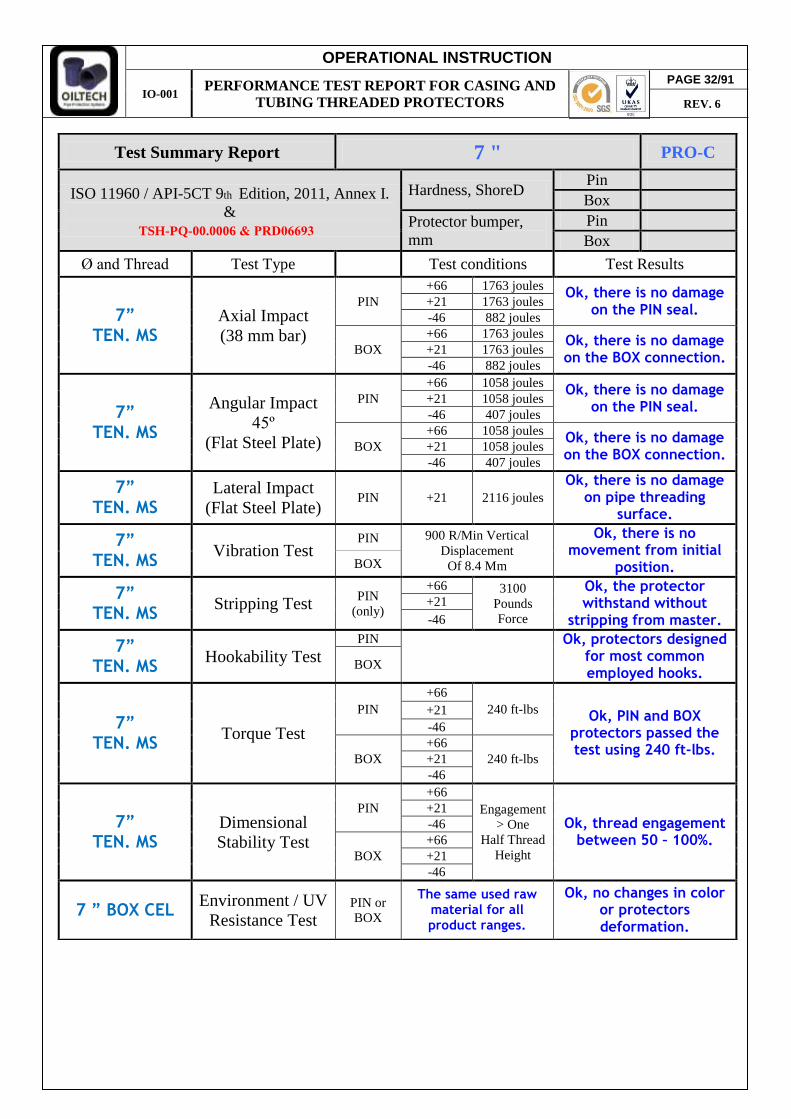
Test Summary Report 7 " PRO-C
ISO 11960 / API-5CT 9th Edition, 2011, Annex I. &
Hardness, ShoreD Pin Box
Protector bumper, mm
Pin Box
Ø and Thread Test Type Test conditions Test Results
7” TEN. MS
Axial Impact (38 mm bar)
PIN +66 1763 joules
Ok, there is no damage on the PIN seal.
+21 1763 joules -46 882 joules
BOX +66 1763 joules
Ok, there is no damage on the BOX connection.
+21 1763 joules -46 882 joules
7” TEN. MS
Angular Impact 45º
(Flat Steel Plate)
PIN +66 1058 joules
Ok, there is no damage on the PIN seal.
+21 1058 joules -46 407 joules
BOX +66 1058 joules
Ok, there is no damage on the BOX connection.
+21 1058 joules -46 407 joules
7” TEN. MS
Lateral Impact (Flat Steel Plate)
PIN +21 2116 joules Ok, there is no damage
on pipe threading surface.
7” TEN. MS
Vibration Test PIN 900 R/Min Vertical
Displacement Of 8.4 Mm
Ok, there is no movement from initial
position. BOX
7” TEN. MS
Stripping Test PIN (only)
+66 3100 Pounds Force
Ok, the protector withstand without
stripping from master. +21 -46
7” TEN. MS
Hookability Test PIN
Ok, protectors designed
for most common employed hooks.
BOX
7” TEN. MS
Torque Test
PIN +66
240 ft-lbs Ok, PIN and BOX
protectors passed the test using 240 ft-lbs.
+21 -46
BOX +66
240 ft-lbs +21 -46
7” TEN. MS
Dimensional Stability Test
PIN +66
Engagement > One
Half Thread Height
Ok, thread engagement between 50 – 100%.
+21 -46
BOX +66 +21 -46
7 ” BOX CEL Environment / UV Resistance Test
PIN or BOX
The same used raw material for all product ranges.
Ok, no changes in color or protectors deformation.
PAGE 32/91
REV. 6
TSH-PQ-00.0006 & PRD06693

OPERATIONAL INSTRUCTION
IO-001 PERFORMANCE TEST REPORT FOR CASING AND
TUBING THREADED PROTECTORS
7 “ TEN. MS Axial Impact Resistance Test
PIN PROTECTOR
T (temperature) = + 66 ºC; E (energy) = 1763 J W (weight) = Hitter weight + Steel bar weight = 220 + 7 = 227 kg h (free fall height) = E / W * g0 = 1763 / 227 * 9.81 = 79,2 cm
H (total height) = h + master height = 79,2 + 33,5 = 112,7 cm
BEFORE IMPACT IMPACT PROTECTOR AFTER
IMPACT
CONNECTION AFTER
IMPACT
TEST RESULT: Ok, there is no damage on the PIN seal. T (temperature) = + 21 ºC; E (energy) = 1763 J W (weight) = Hitter weight + Steel bar weight = 220 + 7 = 227 kg h (free fall height) = E / W * g0 = 1763 / 227 * 9.81 = 79,2 cm
H (total height) = h + master height = 79,2 + 33,5 = 112,7 cm
TEST RESULT: Ok, there is no damage on the PIN seal. T (temperature) = -46 ºC; E (energy) = 882 J W (weight) = Hitter weight + Steel bar weight = 136 + 7 = 143 kg h (free fall height) = E / W * g0 = 882 / 143 * 9.81 = 62,9 cm
H (total height) = h + master height = 62,9 + 33,5 = 96,4 cm
BEFORE IMPACT IMPACT PROTECTOR AFTER
IMPACT
CONNECTION AFTER
IMPACT
TEST RESULT: Ok, there is no damage on the PIN seal.
TEST TEMPERATURE TEST RESULT REMARCS
+66 0C OK +21 0C OK -46 0C OK
PAGE 33/91
REV. 6

OPERATIONAL INSTRUCTION
IO-001 PERFORMANCE TEST REPORT FOR CASING AND
TUBING THREADED PROTECTORS
BOX PROTECTOR
T (temperature) = + 66 ºC; E (energy) = 1763 J W (weight) = Hitter weight + Steel bar weight = 220 + 7 = 227 kg h (free fall height) = E / W * g0 = 1763 / 227 * 9.81 = 79,2 cm
H (total height) = h + master height = 79,2 + 32 = 111,2 cm
BEFORE IMPACT IMPACT PROTECTOR AFTER
IMPACT
CONNECTION AFTER
IMPACT
TEST RESULT: Ok, there is no damage on the BOX connection. T (temperature) = + 21 ºC; E (energy) = 1763 J W (weight) = Hitter weight + Steel bar weight = 220 + 7 = 227 kg h (free fall height) = E / W * g0 = 1763 / 227 * 9.81 = 79,2 cm
H (total height) = h + master height = 79,2 + 32 = 111,2 cm
TEST RESULT: Ok, there is no damage on the BOX connection. T (temperature) = -46 ºC; E (energy) = 882 J W (weight) = Hitter weight + Steel bar weight = 136 + 7 = 143 kg h (free fall height) = E / W * g0 = 882 / 143 * 9.81 = 62,9 cm
H (total height) = h + master height = 62,9 + 32 = 94,9 cm
BEFORE IMPACT IMPACT PROTECTOR AFTER
IMPACT CONNECTION AFTER
IMPACT
TEST RESULT: Ok, there is no damage on the BOX connection.
TEST TEMPERATURE TEST RESULT REMARCS
+66 0C OK +21 0C OK -46 0C OK
PAGE 34/91
REV. 6

OPERATIONAL INSTRUCTION
IO-001 PERFORMANCE TEST REPORT FOR CASING AND
TUBING THREADED PROTECTORS
7 “ TEN. MS Angular Impact Resistance Test
PIN PROTECTOR
T (temperature) = + 66 ºC; E (energy) = 1058 J W (weight) = Hitter weight = 136 kg h (free fall height) = E / W * g0 = 1058 / 136 * 9.81 = 79,3 cm
H (total height) = h + master height = 79,3 + 40 = 119,3 cm
BEFORE IMPACT IMPACT PROTECTOR AFTER
IMPACT
CONNECTION AFTER
IMPACT
TEST RESULT: Ok, there is no damage on the PIN seal. T (temperature) = + 21 ºC; E (energy) = 1058 J W (weight) = Hitter weight = 136 kg h (free fall height) = E / W * g0 = 1058 / 136 * 9.81 = 79,3 cm
H (total height) = h + master height = 79,3 + 40 = 119,3 cm
TEST RESULT: Ok, there is no damage on the PIN seal. T (temperature) = -46 ºC; E (energy) = 407 J W (weight) = Hitter weight = 80 kg h (free fall height) = E / W * g0 = 407 / 80 * 9.81 = 51,9 (min 61 cm.)
H (total height) = h + master height = 61 + 40 = 101 cm
BEFORE IMPACT IMPACT PROTECTOR AFTER
IMPACT CONNECTION AFTER
IMPACT
TEST RESULT: Ok, there is no damage on the PIN seal.
TEST TEMPERATURE TEST RESULT REMARCS
+66 0C OK +21 0C OK -46 0C OK
PAGE 35/91
REV. 6
OPERATIONAL INSTRUCTION
IO-001 PERFORMANCE TEST REPORT FOR CASING AND
TUBING THREADED PROTECTORS
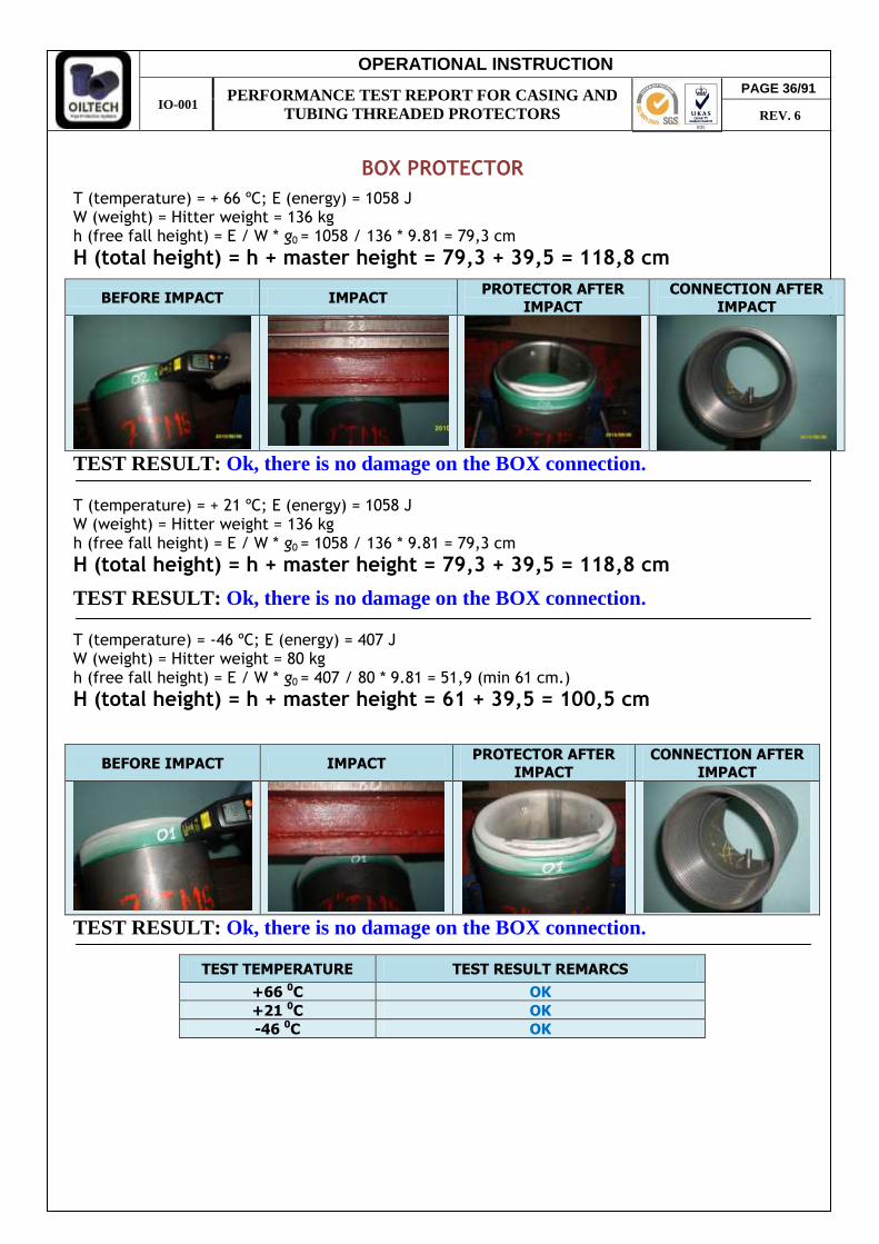
BOX PROTECTOR
T (temperature) = + 66 ºC; E (energy) = 1058 J W (weight) = Hitter weight = 136 kg h (free fall height) = E / W * g0 = 1058 / 136 * 9.81 = 79,3 cm
H (total height) = h + master height = 79,3 + 39,5 = 118,8 cm
BEFORE IMPACT IMPACT PROTECTOR AFTER
IMPACT
CONNECTION AFTER
IMPACT
TEST RESULT: Ok, there is no damage on the BOX connection. T (temperature) = + 21 ºC; E (energy) = 1058 J W (weight) = Hitter weight = 136 kg h (free fall height) = E / W * g0 = 1058 / 136 * 9.81 = 79,3 cm
H (total height) = h + master height = 79,3 + 39,5 = 118,8 cm
TEST RESULT: Ok, there is no damage on the BOX connection. T (temperature) = -46 ºC; E (energy) = 407 J W (weight) = Hitter weight = 80 kg h (free fall height) = E / W * g0 = 407 / 80 * 9.81 = 51,9 (min 61 cm.)
H (total height) = h + master height = 61 + 39,5 = 100,5 cm
BEFORE IMPACT IMPACT PROTECTOR AFTER
IMPACT
CONNECTION AFTER
IMPACT
TEST RESULT: Ok, there is no damage on the BOX connection.
TEST TEMPERATURE TEST RESULT REMARCS
+66 0C OK +21 0C OK -46 0C OK
PAGE 36/91
REV. 6
OPERATIONAL INSTRUCTION
IO-001 PERFORMANCE TEST REPORT FOR CASING AND
TUBING THREADED PROTECTORS
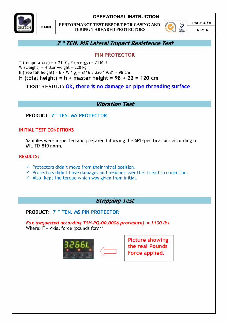
7 “ TEN. MS Lateral Impact Resistance Test
PIN PROTECTOR
T (temperature) = + 21 ºC; E (energy) = 2116 J W (weight) = Hitter weight = 220 kg h (free fall height) = E / W * g0 = 2116 / 220 * 9.81 = 98 cm
H (total height) = h + master height = 98 + 22 = 120 cm
TEST RESULT: Ok, there is no damage on pipe threading surface.
Vibration Test PRODUCT: 7” TEN. MS PROTECTOR
INITIAL TEST CONDITIONS
Samples were inspected and prepared following the API specifications according to MIL-TD-810 norm.
RESULTS: Protectors didn’t move from their initial position. Protectors didn’t have damages and residues over the thread’s connection. Also, kept the torque which was given from initial.
Stripping Test
PRODUCT: 7 ” TEN. MS PIN PROTECTOR
Fax (requested according TSH-PQ-00.0006 procedure) = 3100 lbs Where: F = Axial force (pounds force)
PAGE 37/91
REV. 6
OPERATIONAL INSTRUCTION
IO-001 PERFORMANCE TEST REPORT FOR CASING AND
TUBING THREADED PROTECTORS
Hookability (Liftability) Test
According to the general specification the product of the Line PRO-C (metal composite protectors) and PRO-T (Fully plastic Heavy duty), the shape of the liftable side is conform to most common hooks employed in the rigs. The test has been performed on 5 ½” and 9 5/8” sizes with the appropriate range of hooks type UNI4395 and DIN 15401.
Torque Test
PRODUCT: 7” TEN. MS PROTECTORS
To evaluate the torque stripping resistance of the thread protector during make-up and
attempt should be made to "strip-out" the pin and box protector was applied 240 ft-lbs "strip-out" force torque as described in the specification.
Both PIN and BOX protectors passed the test.
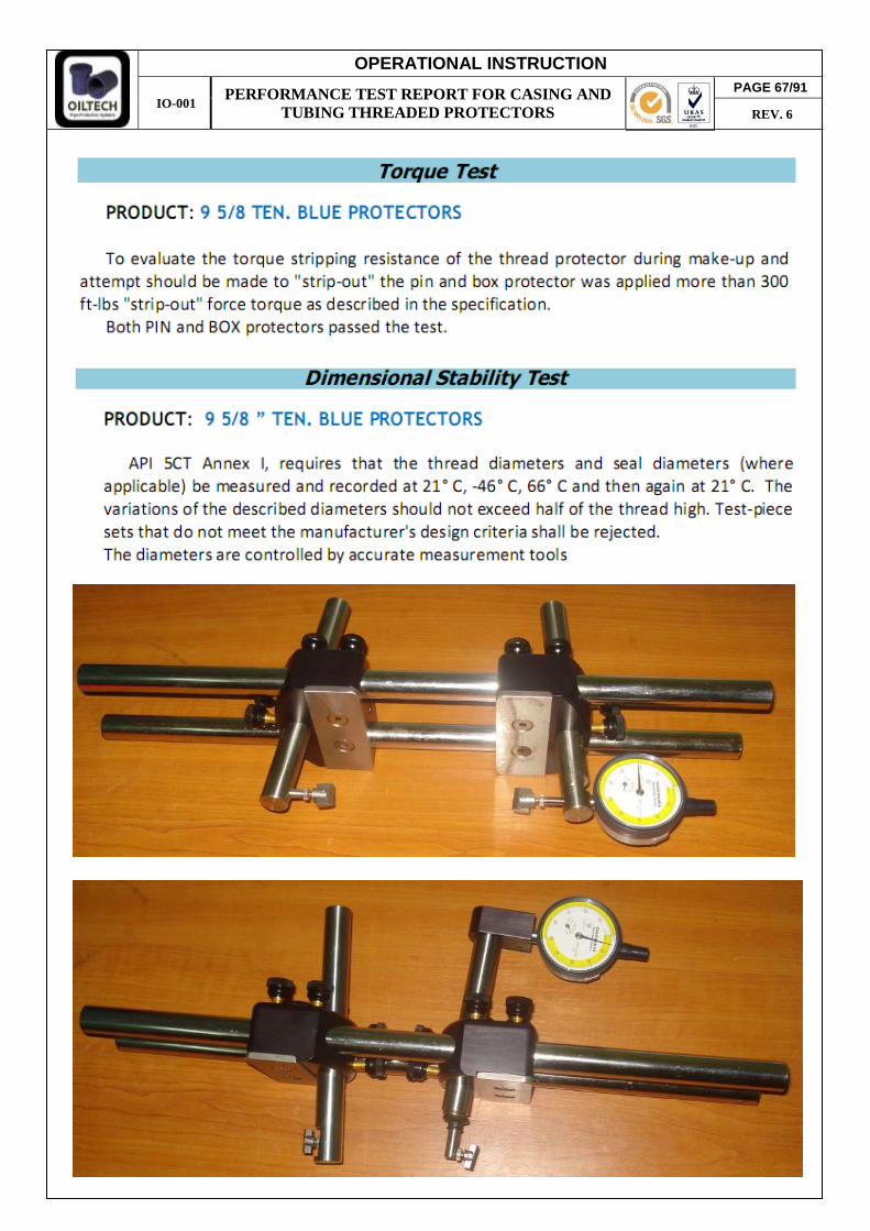
Dimensional Stability Test PRODUCT: 7” TEN. MS PRO-C CENL PROTECTORS
API 5CT Annex I, requires that the thread diameters and seal diameters (where applicable)
be measured and recorded at 21° C, -46° C, 66° C and then again at 21° C. The variations of the described diameters should not exceed half of the thread high. Test-piece sets that do not meet the manufacturer's design criteria shall be rejected.
PAGE 38/91
REV. 6
The sets are measured on the defined areas
The diameters are controlled by accurate measurement tools

OPERATIONAL INSTRUCTION
IO-001 PERFORMANCE TEST REPORT FOR CASING AND
TUBING THREADED PROTECTORS
The pipe connections are obviously measured exactly in the corresponding diameters so
that protector and pipe diameters are comparable. The sets are first measured and recorded at 21°C. Then the sets are cooled in a liquid nitrogen bath: When the specified temperature is
reached (-46°C), the sets are controlled again. Then the protectors are heated in an oven and when the specified temperature is reached
(66°C), the sets are measured and controlled again. Those are finally checked again when reaching the room temperature (21°C).
FINAL TEST RESULTS Ok, thread engagement between 50 – 100%.
Environment / UV Resistance Test
PRODUCT: 7 ” PRO-C CEL BOX PROTECTORS
INITIAL TEST CONDITIONS Protectors were manufactured and painted with all color types (purple, green, black) used in production. The samples were stored outside on direct UV impact. Four initial states were applied on each type of paint color: 1. Protector cleaned with solvent, after painted, like usually prepared for delivery.
Exposed outside to direct UV rays. (dry) 2. Protector cleaned with solvent and painted, filled with water. Exposed outside to
direct UV rays. (water)
PAGE 39/91
REV. 6

OPERATIONAL INSTRUCTION
IO-001 PERFORMANCE TEST REPORT FOR CASING AND
TUBING THREADED PROTECTORS
3. Protector not cleaned after pressing process. Painted over oiled surface and exposed outside to direct UV rays. (Non cleaned)
4. Protector cleaned with solvent, refrigerated at -25C0 and painted over the condensate metal surface. Exposed outside to direct UV rays.
Test period for protector storage - at least one year. Positive result to respect test requirements: no protector damages, paint detaching or color changes are accepted with normal painting applied process. FINAL TEST RESULTS
1. Painted surface changes non essential. Applied paint didn’t detach from steel but only from plastic surface of protector (dry).
PAGE 40/91
REV. 6
OPERATIONAL INSTRUCTION
IO-001 PERFORMANCE TEST REPORT FOR CASING AND
TUBING THREADED PROTECTORS
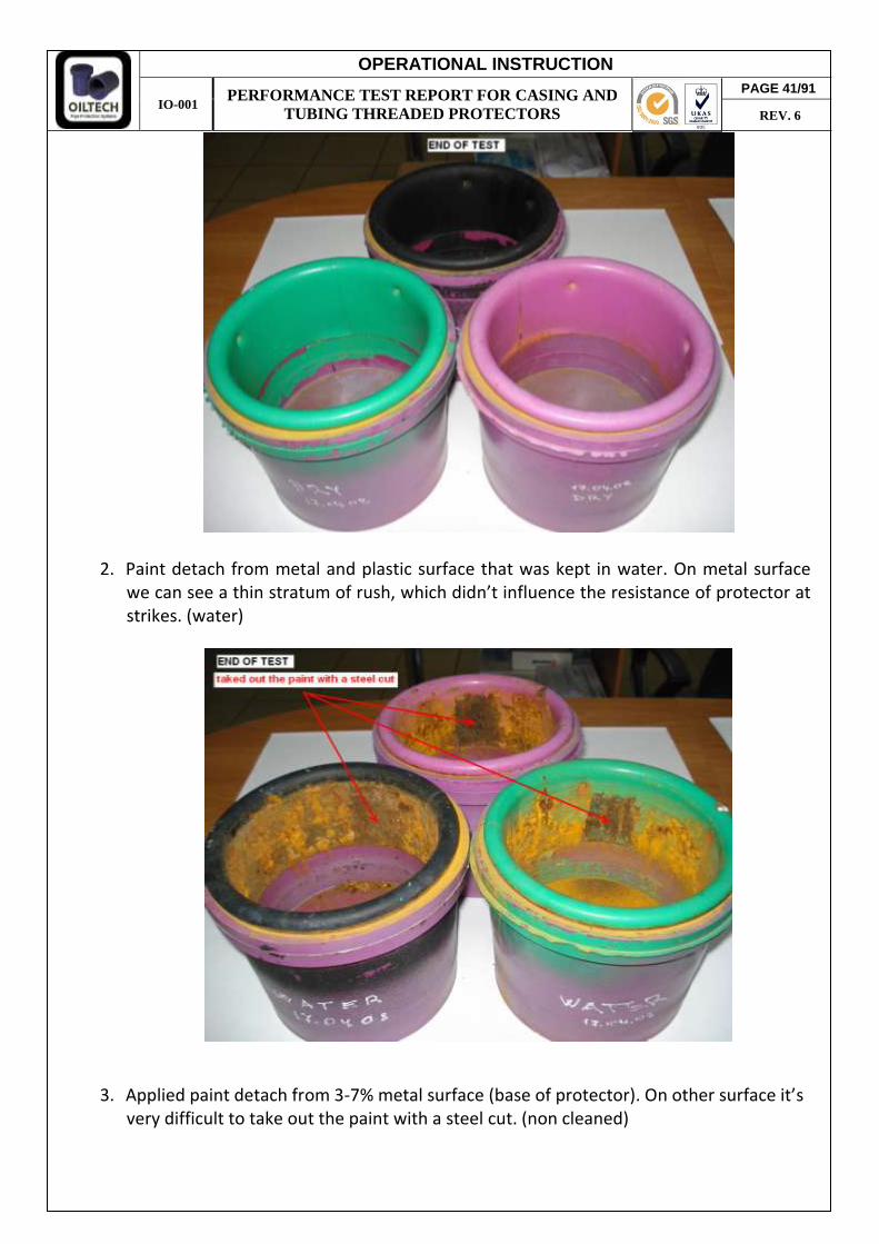
2. Paint detach from metal and plastic surface that was kept in water. On metal surface we can see a thin stratum of rush, which didn’t influence the resistance of protector at strikes. (water)
3. Applied paint detach from 3-7% metal surface (base of protector). On other surface it’s very difficult to take out the paint with a steel cut. (non cleaned)
PAGE 41/91
REV. 6
OPERATIONAL INSTRUCTION
IO-001 PERFORMANCE TEST REPORT FOR CASING AND
TUBING THREADED PROTECTORS
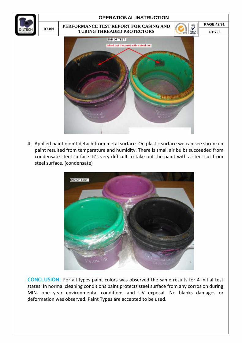
4. Applied paint didn’t detach from metal surface. On plastic surface we can see shrunken paint resulted from temperature and humidity. There is small air bulbs succeeded from condensate steel surface. It’s very difficult to take out the paint with a steel cut from steel surface. (condensate)
CONCLUSION: For all types paint colors was observed the same results for 4 initial test states. In normal cleaning conditions paint protects steel surface from any corrosion during MIN. one year environmental conditions and UV exposal. No blanks damages or deformation was observed. Paint Types are accepted to be used.
PAGE 42/91
REV. 6

OPERATIONAL INSTRUCTION
IO-001 PERFORMANCE TEST REPORT FOR CASING AND
TUBING THREADED PROTECTORS
Test Summary Report 7 " BSC-T&C
ISO 11960 / API-5CT 9th Edition, 2011, Annex I. &
Hardness, ShoreD Pin Box
Protector bumper, mm
Pin Box
Ø and Thread Test Type Test conditions Test Results
7” LCSG/CSG
Axial Impact (38 mm bar)
PIN +66 1763 joules
Ok, there is no damage on the PIN seal.
+21 1763 joules -46 882 joules
BOX +66 1763 joules
Ok, there is no damage on the BOX connection.
+21 1763 joules -46 882 joules
7” LCSG/CSG
Angular Impact 45º
(Flat Steel Plate)
PIN +66 1058 joules
Ok, there is no damage on the PIN seal.
+21 1058 joules -46 407 joules
BOX +66 1058 joules
Ok, there is no damage on the BOX connection.
+21 1058 joules -46 407 joules
7” LCSG/CSG
Lateral Impact (Flat Steel Plate)
PIN +21 2116 joules Ok, there is no damage
on pipe threading surface.
7” LCSG/CSG
Vibration Test PIN 900 R/Min Vertical
Displacement Of 8.4 Mm
Ok, there is no movement from initial
position. BOX
7” LCSG/CSG
Stripping Test PIN (only)
+66 3100 Pounds Force
Ok, the protector withstand without
stripping from master. +21 -46
7” LCSG/CSG
Hookability Test PIN
Ok, protectors designed
for most common employed hooks.
BOX
7” LCSG/CSG
Torque Test
PIN +66
240 ft-lbs Ok, PIN and BOX
protectors passed the test using 240 ft-lbs.
+21 -46
BOX +66
240 ft-lbs +21 -46
7” LCSG/CSG
Dimensional Stability Test
PIN +66
Engagement > One
Half Thread Height
Ok, thread engagement between 50 – 100%.
+21 -46
BOX +66 +21 -46
5 ½ ” PIN CEL 7 ” BOX CEL
Environment / UV Resistance Test
PIN or BOX
The same used raw material for all product ranges.
Ok, no changes in color or protectors deformation.
PAGE 43/91
REV. 6
TSH-PQ-00.0006 & PRD06693

OPERATIONAL INSTRUCTION
IO-001 PERFORMANCE TEST REPORT FOR CASING AND
TUBING THREADED PROTECTORS
7 “ LCSG/CSG Axial Impact Resistance Test
PIN PROTECTOR
T (temperature) = + 66 ºC; E (energy) = 1763 J W (weight) = Hitter weight + Steel bar weight = 220 + 7 = 227 kg h (free fall height) = E / W * g0 = 1763 / 227 * 9.81 = 79,2 cm
H (total height) = h + master height = 79,2 + 23 = 102,2 cm
BEFORE IMPACT IMPACT PROTECTOR AFTER
IMPACT CONNECTION AFTER
IMPACT
TEST RESULT: Ok, there is no damage on the PIN seal. T (temperature) = + 21 ºC; E (energy) = 1763 J W (weight) = Hitter weight + Steel bar weight = 220 + 7 = 227 kg h (free fall height) = E / W * g0 = 1763 / 227 * 9.81 = 79,2 cm
H (total height) = h + master height = 79,2 + 23 = 102,2 cm
BEFORE IMPACT IMPACT PROTECTOR AFTER
IMPACT CONNECTION AFTER
IMPACT
TEST RESULT: Ok, there is no damage on the PIN seal. T (temperature) = -46 ºC; E (energy) = 882 J W (weight) = Hitter weight + Steel bar weight = 136 + 7 = 143 kg h (free fall height) = E / W * g0 = 882 / 143 * 9.81 = 62,9 cm
H (total height) = h + master height = 62,9 + 23 = 85,9 cm
BEFORE IMPACT IMPACT PROTECTOR AFTER
IMPACT CONNECTION AFTER
IMPACT
TEST RESULT: Ok, there is no damage on the PIN seal.
TEST TEMPERATURE TEST RESULT REMARCS
+66 0C OK +21 0C OK -46 0C OK
PAGE 44/91
REV. 6

OPERATIONAL INSTRUCTION
IO-001 PERFORMANCE TEST REPORT FOR CASING AND
TUBING THREADED PROTECTORS
BOX PROTECTOR
T (temperature) = + 66 ºC; E (energy) = 1763 J W (weight) = Hitter weight + Steel bar weight = 220 + 7 = 227 kg h (free fall height) = E / W * g0 = 1763 / 227 * 9.81 = 79,2 cm
H (total height) = h + master height = 79,2 + 25,5 = 104,7 cm
BEFORE IMPACT IMPACT PROTECTOR AFTER
IMPACT CONNECTION AFTER
IMPACT
TEST RESULT: Ok, there is no damage on the BOX connection. T (temperature) = + 21 ºC; E (energy) = 1763 J W (weight) = Hitter weight + Steel bar weight = 220 + 7 = 227 kg h (free fall height) = E / W * g0 = 1763 / 227 * 9.81 = 79,2 cm
H (total height) = h + master height = 79,2 + 25,5 = 104,7 cm
BEFORE IMPACT IMPACT PROTECTOR AFTER
IMPACT CONNECTION AFTER
IMPACT
TEST RESULT: Ok, there is no damage on the BOX connection. T (temperature) = -46 ºC; E (energy) = 882 J W (weight) = Hitter weight + Steel bar weight = 136 + 7 = 143 kg h (free fall height) = E / W * g0 = 882 / 143 * 9.81 = 62,9 cm
H (total height) = h + master height = 62,9 + 25,5 = 88,4 cm
BEFORE IMPACT IMPACT PROTECTOR AFTER
IMPACT
CONNECTION AFTER
IMPACT
TEST RESULT: Ok, there is no damage on the BOX connection.
TEST TEMPERATURE TEST RESULT REMARCS
+66 0C OK +21 0C OK -46 0C OK
PAGE 45/91
REV. 6

OPERATIONAL INSTRUCTION
IO-001 PERFORMANCE TEST REPORT FOR CASING AND
TUBING THREADED PROTECTORS
7 “ LSCG/CSG Angular Impact Resistance Test
PIN PROTECTOR
T (temperature) = + 66 ºC; E (energy) = 1058 J W (weight) = Hitter weight = 136 kg h (free fall height) = E / W * g0 = 1058 / 136 * 9.81 = 79,3 cm
H (total height) = h + master height = 79,3 + 32 = 111,3 cm
BEFORE IMPACT IMPACT PROTECTOR AFTER
IMPACT CONNECTION AFTER
IMPACT
TEST RESULT: Ok, there is no damage on the PIN seal. T (temperature) = + 21 ºC; E (energy) = 1058 J W (weight) = Hitter weight = 136 kg h (free fall height) = E / W * g0 = 1058 / 136 * 9.81 = 79,3 cm
H (total height) = h + master height = 79,3 + 32 = 111,3 cm
BEFORE IMPACT IMPACT PROTECTOR AFTER
IMPACT CONNECTION AFTER
IMPACT
TEST RESULT: Ok, there is no damage on the PIN seal. T (temperature) = -46 ºC; E (energy) = 407 J W (weight) = Hitter weight = 80 kg h (free fall height) = E / W * g0 = 407 / 80 * 9.81 = 51,9 (min 61 cm.)
H (total height) = h + master height = 61 + 32 = 94 cm
BEFORE IMPACT IMPACT PROTECTOR AFTER
IMPACT CONNECTION AFTER
IMPACT
TEST RESULT: Ok, there is no damage on the PIN seal.
TEST TEMPERATURE TEST RESULT REMARCS
+66 0C OK +21 0C OK -46 0C OK
PAGE 46/91
REV. 6
OPERATIONAL INSTRUCTION
IO-001 PERFORMANCE TEST REPORT FOR CASING AND
TUBING THREADED PROTECTORS
BOX PROTECTOR
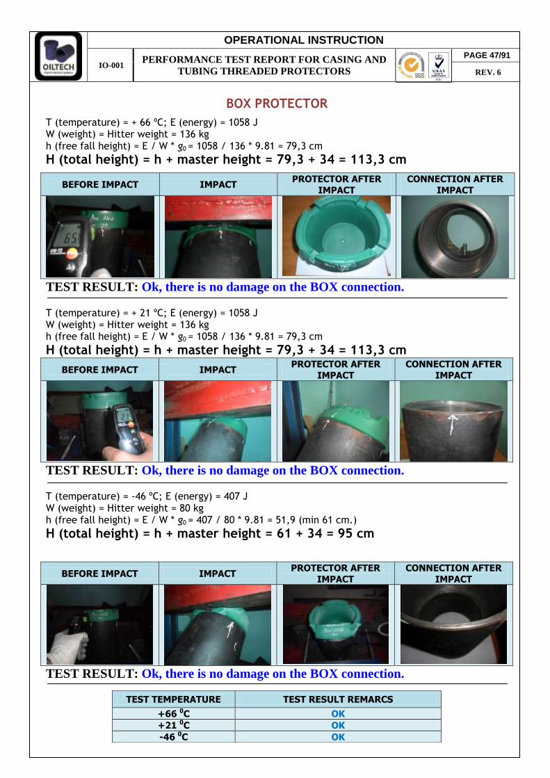
T (temperature) = + 66 ºC; E (energy) = 1058 J W (weight) = Hitter weight = 136 kg h (free fall height) = E / W * g0 = 1058 / 136 * 9.81 = 79,3 cm
H (total height) = h + master height = 79,3 + 34 = 113,3 cm
BEFORE IMPACT IMPACT PROTECTOR AFTER
IMPACT
CONNECTION AFTER
IMPACT
TEST RESULT: Ok, there is no damage on the BOX connection. T (temperature) = + 21 ºC; E (energy) = 1058 J W (weight) = Hitter weight = 136 kg h (free fall height) = E / W * g0 = 1058 / 136 * 9.81 = 79,3 cm
H (total height) = h + master height = 79,3 + 34 = 113,3 cm
BEFORE IMPACT IMPACT PROTECTOR AFTER
IMPACT
CONNECTION AFTER
IMPACT
TEST RESULT: Ok, there is no damage on the BOX connection. T (temperature) = -46 ºC; E (energy) = 407 J W (weight) = Hitter weight = 80 kg h (free fall height) = E / W * g0 = 407 / 80 * 9.81 = 51,9 (min 61 cm.)
H (total height) = h + master height = 61 + 34 = 95 cm
BEFORE IMPACT IMPACT PROTECTOR AFTER
IMPACT
CONNECTION AFTER
IMPACT
TEST RESULT: Ok, there is no damage on the BOX connection.
TEST TEMPERATURE TEST RESULT REMARCS
+66 0C OK +21 0C OK -46 0C OK
PAGE 47/91
REV. 6

OPERATIONAL INSTRUCTION
IO-001 PERFORMANCE TEST REPORT FOR CASING AND
TUBING THREADED PROTECTORS
7 “ LCSG/CSG Lateral Impact Resistance Test
PIN PROTECTOR
T (temperature) = + 21 ºC; E (energy) = 2116 J W (weight) = Hitter weight = 220 kg h (free fall height) = E / W * g0 = 2116 / 220 * 9.81 = 98 cm
H (total height) = h + master height = 98 + 23 = 121 cm
TEST RESULT: Ok, there is no damage on pipe threading surface.
Vibration Test PRODUCT: 7” LCSG/CSG PROTECTOR
INITIAL TEST CONDITIONS
Samples were inspected and prepared following the API specifications according to MIL-TD-810 norm.
RESULTS: Protectors didn’t move from their initial position. Protectors didn’t have damages and residues over the thread’s connection. Also, kept the torque which was given from initial.
Stripping Test
PRODUCT: 7 ” LCSG/CSG PIN PROTECTOR
Fax (requested according TSH-PQ-00.0006 procedure) = 3100 lbs Where: F = Axial force (pounds force)
Hookability (Liftability) Test
According to the general specification the product of the Line PRO-C (metal composite protectors) and PRO-T / BSC-T&C (Fully plastic Heavy duty), the shape of the liftable side is conform to most common hooks employed in the rigs. The test has been performed on 5 ½” and 9 5/8” sizes with the appropriate range of hooks type UNI4395 and DIN 15401.
PAGE 48/91
REV. 6

OPERATIONAL INSTRUCTION
IO-001 PERFORMANCE TEST REPORT FOR CASING AND
TUBING THREADED PROTECTORS
Torque Test
PRODUCT: 7” LCSG/CSG PROTECTORS
To evaluate the torque stripping resistance of the thread protector during make-up and
attempt should be made to "strip-out" the pin and box protector was applied 240 ft-lbs (325 N/m) "strip-out" force torque as described in the specification.
Both PIN and BOX protectors passed the test.
Dimensional Stability Test PRODUCT: 7” LCSG/CSG PROTECTORS API 5CT Annex I, requires that the thread diameters and seal diameters (where applicable)
be measured and recorded at 21° C, -46° C, 66° C and then again at 21° C. The variations of the described diameters should not exceed half of the thread high. Test-piece sets that do not meet the manufacturer's design criteria shall be rejected.
The sets are measured on the defined areas The pipe connections are obviously measured exactly in the corresponding diameters so
that protector and pipe diameters are comparable. The sets are first measured and recorded at 21°C. Then the sets are cooled in a liquid nitrogen bath: When the specified temperature is
reached (-46°C), the sets are controlled again. Then the protectors are heated in an oven and when the specified temperature is reached
(66°C), the sets are measured and controlled again. Those are finally checked again when reaching the room temperature (21°C).
FINAL TEST RESULTS Ok, thread engagement between 50 – 100%.
PAGE 49/91
REV. 6
OPERATIONAL INSTRUCTION
IO-001 PERFORMANCE TEST REPORT FOR CASING AND
TUBING THREADED PROTECTORS
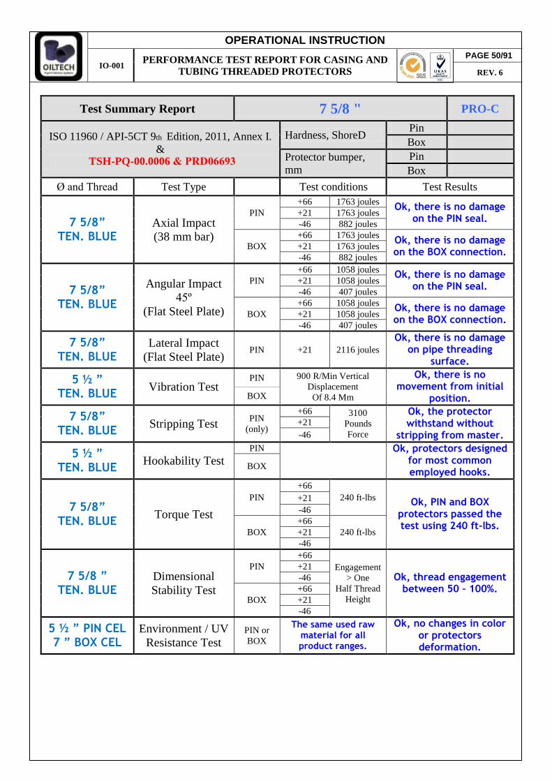
Test Summary Report 7 5/8 " PRO-C
ISO 11960 / API-5CT 9th Edition, 2011, Annex I. &
Hardness, ShoreD Pin Box
Protector bumper, mm
Pin Box
Ø and Thread Test Type Test conditions Test Results
7 5/8” TEN. BLUE
Axial Impact (38 mm bar)
PIN +66 1763 joules
Ok, there is no damage on the PIN seal.
+21 1763 joules -46 882 joules
BOX +66 1763 joules
Ok, there is no damage on the BOX connection.
+21 1763 joules -46 882 joules
7 5/8” TEN. BLUE
Angular Impact 45º
(Flat Steel Plate)
PIN +66 1058 joules
Ok, there is no damage on the PIN seal.
+21 1058 joules -46 407 joules
BOX +66 1058 joules
Ok, there is no damage on the BOX connection.
+21 1058 joules -46 407 joules
7 5/8” TEN. BLUE
Lateral Impact (Flat Steel Plate)
PIN +21 2116 joules Ok, there is no damage
on pipe threading surface.
5 ½ ” TEN. BLUE
Vibration Test PIN 900 R/Min Vertical
Displacement Of 8.4 Mm
Ok, there is no movement from initial
position. BOX
7 5/8” TEN. BLUE
Stripping Test PIN (only)
+66 3100 Pounds Force
Ok, the protector withstand without
stripping from master. +21 -46
5 ½ ” TEN. BLUE
Hookability Test PIN
Ok, protectors designed
for most common employed hooks.
BOX
7 5/8” TEN. BLUE
Torque Test
PIN +66
240 ft-lbs Ok, PIN and BOX
protectors passed the test using 240 ft-lbs.
+21 -46
BOX +66
240 ft-lbs +21 -46
7 5/8 ” TEN. BLUE
Dimensional Stability Test
PIN +66
Engagement > One
Half Thread Height
Ok, thread engagement between 50 – 100%.
+21 -46
BOX +66 +21 -46
5 ½ ” PIN CEL 7 ” BOX CEL
Environment / UV Resistance Test
PIN or BOX
The same used raw material for all product ranges.
Ok, no changes in color or protectors deformation.
PAGE 50/91
REV. 6
TSH-PQ-00.0006 & PRD06693
OPERATIONAL INSTRUCTION
IO-001 PERFORMANCE TEST REPORT FOR CASING AND
TUBING THREADED PROTECTORS
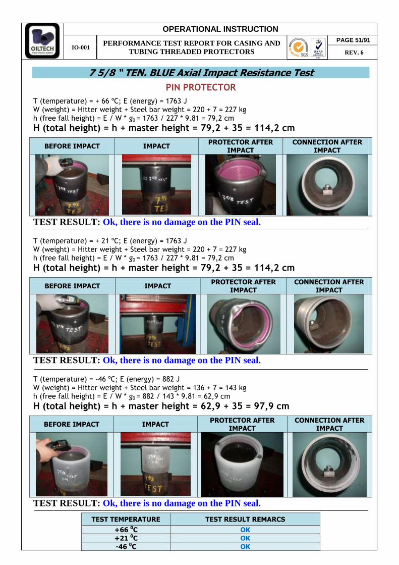
7 5/8 “ TEN. BLUE Axial Impact Resistance Test
PIN PROTECTOR
T (temperature) = + 66 ºC; E (energy) = 1763 J W (weight) = Hitter weight + Steel bar weight = 220 + 7 = 227 kg h (free fall height) = E / W * g0 = 1763 / 227 * 9.81 = 79,2 cm
H (total height) = h + master height = 79,2 + 35 = 114,2 cm
BEFORE IMPACT IMPACT PROTECTOR AFTER
IMPACT
CONNECTION AFTER
IMPACT
TEST RESULT: Ok, there is no damage on the PIN seal. T (temperature) = + 21 ºC; E (energy) = 1763 J W (weight) = Hitter weight + Steel bar weight = 220 + 7 = 227 kg h (free fall height) = E / W * g0 = 1763 / 227 * 9.81 = 79,2 cm
H (total height) = h + master height = 79,2 + 35 = 114,2 cm
BEFORE IMPACT IMPACT PROTECTOR AFTER
IMPACT
CONNECTION AFTER
IMPACT
TEST RESULT: Ok, there is no damage on the PIN seal. T (temperature) = -46 ºC; E (energy) = 882 J W (weight) = Hitter weight + Steel bar weight = 136 + 7 = 143 kg h (free fall height) = E / W * g0 = 882 / 143 * 9.81 = 62,9 cm
H (total height) = h + master height = 62,9 + 35 = 97,9 cm
BEFORE IMPACT IMPACT PROTECTOR AFTER
IMPACT CONNECTION AFTER
IMPACT
TEST RESULT: Ok, there is no damage on the PIN seal.
TEST TEMPERATURE TEST RESULT REMARCS
+66 0C OK +21 0C OK -46 0C OK
PAGE 51/91
REV. 6
OPERATIONAL INSTRUCTION
IO-001 PERFORMANCE TEST REPORT FOR CASING AND
TUBING THREADED PROTECTORS
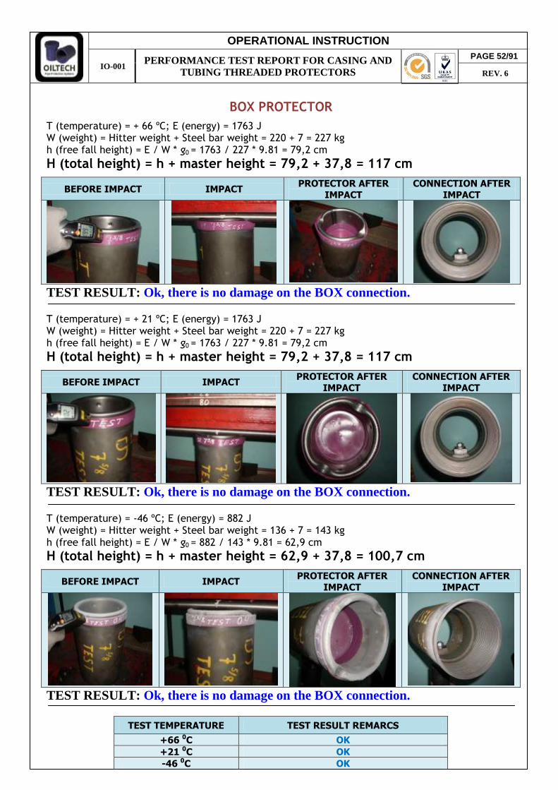
BOX PROTECTOR
T (temperature) = + 66 ºC; E (energy) = 1763 J W (weight) = Hitter weight + Steel bar weight = 220 + 7 = 227 kg h (free fall height) = E / W * g0 = 1763 / 227 * 9.81 = 79,2 cm
H (total height) = h + master height = 79,2 + 37,8 = 117 cm
BEFORE IMPACT IMPACT PROTECTOR AFTER
IMPACT
CONNECTION AFTER
IMPACT
TEST RESULT: Ok, there is no damage on the BOX connection. T (temperature) = + 21 ºC; E (energy) = 1763 J W (weight) = Hitter weight + Steel bar weight = 220 + 7 = 227 kg h (free fall height) = E / W * g0 = 1763 / 227 * 9.81 = 79,2 cm
H (total height) = h + master height = 79,2 + 37,8 = 117 cm
BEFORE IMPACT IMPACT PROTECTOR AFTER
IMPACT
CONNECTION AFTER
IMPACT
TEST RESULT: Ok, there is no damage on the BOX connection. T (temperature) = -46 ºC; E (energy) = 882 J W (weight) = Hitter weight + Steel bar weight = 136 + 7 = 143 kg h (free fall height) = E / W * g0 = 882 / 143 * 9.81 = 62,9 cm
H (total height) = h + master height = 62,9 + 37,8 = 100,7 cm
BEFORE IMPACT IMPACT PROTECTOR AFTER
IMPACT
CONNECTION AFTER
IMPACT
TEST RESULT: Ok, there is no damage on the BOX connection.
TEST TEMPERATURE TEST RESULT REMARCS
+66 0C OK +21 0C OK -46 0C OK
PAGE 52/91
REV. 6

OPERATIONAL INSTRUCTION
IO-001 PERFORMANCE TEST REPORT FOR CASING AND
TUBING THREADED PROTECTORS
7 5/8 “ TEN. BLUE Angular Impact Resistance Test
PIN PROTECTOR
T (temperature) = + 66 ºC; E (energy) = 1058 J W (weight) = Hitter weight = 136 kg h (free fall height) = E / W * g0 = 1058 / 136 * 9.81 = 79,3 cm
H (total height) = h + master height = 79,3 + 45 = 124,3 cm
BEFORE IMPACT IMPACT PROTECTOR AFTER
IMPACT
CONNECTION AFTER
IMPACT
TEST RESULT: Ok, there is no damage on the PIN seal. T (temperature) = + 21 ºC; E (energy) = 1058 J W (weight) = Hitter weight = 136 kg h (free fall height) = E / W * g0 = 1058 / 136 * 9.81 = 79,3 cm
H (total height) = h + master height = 79,3 + 45 = 124,3 cm
BEFORE IMPACT IMPACT PROTECTOR AFTER
IMPACT CONNECTION AFTER
IMPACT
TEST RESULT: Ok, there is no damage on the PIN seal. T (temperature) = -46 ºC; E (energy) = 407 J W (weight) = Hitter weight = 80 kg h (free fall height) = E / W * g0 = 407 / 80 * 9.81 = 51,9 (min 61 cm.)
H (total height) = h + master height = 61 + 45 = 106 cm
BEFORE IMPACT IMPACT PROTECTOR AFTER
IMPACT
CONNECTION AFTER
IMPACT
TEST RESULT: Ok, there is no damage on the PIN seal.
TEST TEMPERATURE TEST RESULT REMARCS
+66 0C OK +21 0C OK -46 0C OK
PAGE 53/91
REV. 6
OPERATIONAL INSTRUCTION
IO-001 PERFORMANCE TEST REPORT FOR CASING AND
TUBING THREADED PROTECTORS
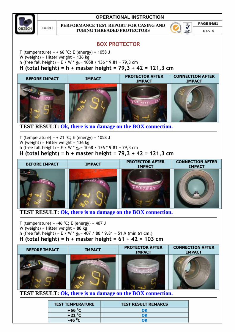
BOX PROTECTOR
T (temperature) = + 66 ºC; E (energy) = 1058 J W (weight) = Hitter weight = 136 kg h (free fall height) = E / W * g0 = 1058 / 136 * 9.81 = 79,3 cm
H (total height) = h + master height = 79,3 + 42 = 121,3 cm
BEFORE IMPACT IMPACT PROTECTOR AFTER
IMPACT
CONNECTION AFTER
IMPACT
TEST RESULT: Ok, there is no damage on the BOX connection. T (temperature) = + 21 ºC; E (energy) = 1058 J W (weight) = Hitter weight = 136 kg h (free fall height) = E / W * g0 = 1058 / 136 * 9.81 = 79,3 cm
H (total height) = h + master height = 79,3 + 42 = 121,3 cm
BEFORE IMPACT IMPACT PROTECTOR AFTER
IMPACT
CONNECTION AFTER
IMPACT
TEST RESULT: Ok, there is no damage on the BOX connection. T (temperature) = -46 ºC; E (energy) = 407 J W (weight) = Hitter weight = 80 kg h (free fall height) = E / W * g0 = 407 / 80 * 9.81 = 51,9 (min 61 cm.)
H (total height) = h + master height = 61 + 42 = 103 cm
BEFORE IMPACT IMPACT PROTECTOR AFTER
IMPACT
CONNECTION AFTER
IMPACT
TEST RESULT: Ok, there is no damage on the BOX connection.
TEST TEMPERATURE TEST RESULT REMARCS
+66 0C OK +21 0C OK -46 0C OK
PAGE 54/91
REV. 6

OPERATIONAL INSTRUCTION
IO-001 PERFORMANCE TEST REPORT FOR CASING AND
TUBING THREADED PROTECTORS
7 5/8 “ TEN. BLUE Lateral Impact Resistance Test
PIN PROTECTOR
T (temperature) = + 21 ºC; E (energy) = 2116 J W (weight) = Hitter weight = 220 kg h (free fall height) = E / W * g0 = 2116 / 220 * 9.81 = 98 cm
H (total height) = h + master height = 98 + 23 = 121 cm
BEFORE IMPACT IMPACT
PROTECTOR AFTER IMPACT
CONNECTION AFTER IMPACT
TEST RESULT: Ok, there is no damage on pipe threading surface.
PAGE 55/91
REV. 6
OPERATIONAL INSTRUCTION
IO-001 PERFORMANCE TEST REPORT FOR CASING AND
TUBING THREADED PROTECTORS
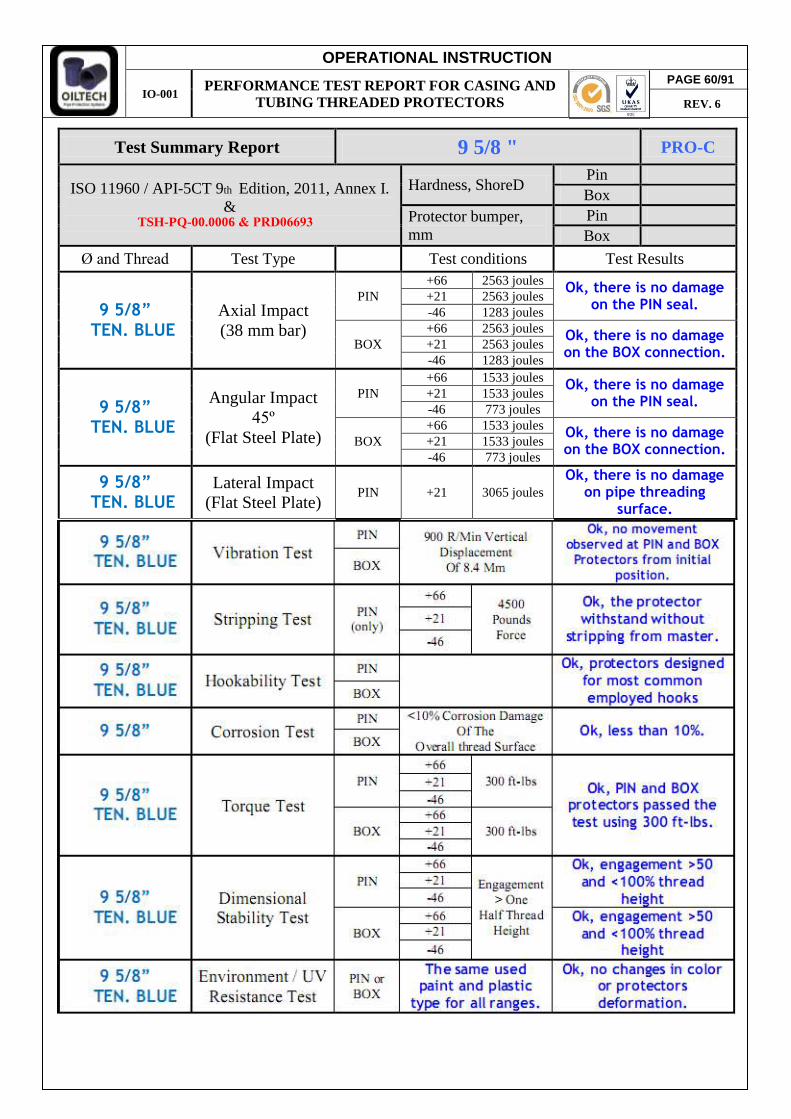
Test Summary Report 9 5/8 " PRO-C
ISO 11960 / API-5CT 9th Edition, 2011, Annex I. &
Hardness, ShoreD Pin Box
Protector bumper, mm
Pin Box
Ø and Thread Test Type Test conditions Test Results
9 5/8” TEN. BLUE
Axial Impact (38 mm bar)
PIN +66 2563 joules
Ok, there is no damage on the PIN seal.
+21 2563 joules -46 1283 joules
BOX +66 2563 joules
Ok, there is no damage on the BOX connection.
+21 2563 joules -46 1283 joules
9 5/8” TEN. BLUE
Angular Impact 45º
(Flat Steel Plate)
PIN +66 1533 joules
Ok, there is no damage on the PIN seal.
+21 1533 joules -46 773 joules
BOX +66 1533 joules
Ok, there is no damage on the BOX connection.
+21 1533 joules -46 773 joules
9 5/8” TEN. BLUE
Lateral Impact (Flat Steel Plate)
PIN +21 3065 joules Ok, there is no damage
on pipe threading surface.
PAGE 60/91
REV. 6
TSH-PQ-00.0006 & PRD06693
OPERATIONAL INSTRUCTION
IO-001 PERFORMANCE TEST REPORT FOR CASING AND
TUBING THREADED PROTECTORS
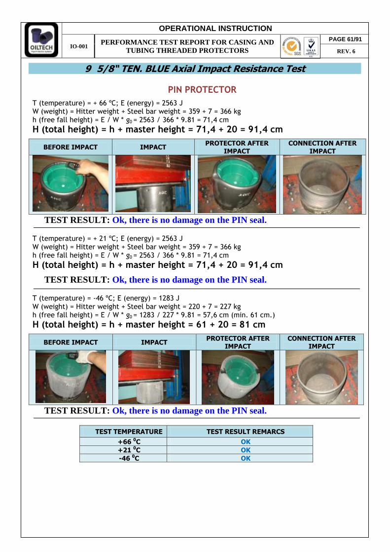
9 5/8“ TEN. BLUE Axial Impact Resistance Test
PIN PROTECTOR
T (temperature) = + 66 ºC; E (energy) = 2563 J W (weight) = Hitter weight + Steel bar weight = 359 + 7 = 366 kg h (free fall height) = E / W * g0 = 2563 / 366 * 9.81 = 71,4 cm
H (total height) = h + master height = 71,4 + 20 = 91,4 cm
BEFORE IMPACT IMPACT PROTECTOR AFTER
IMPACT
CONNECTION AFTER
IMPACT
TEST RESULT: Ok, there is no damage on the PIN seal. T (temperature) = + 21 ºC; E (energy) = 2563 J W (weight) = Hitter weight + Steel bar weight = 359 + 7 = 366 kg h (free fall height) = E / W * g0 = 2563 / 366 * 9.81 = 71,4 cm
H (total height) = h + master height = 71,4 + 20 = 91,4 cm
TEST RESULT: Ok, there is no damage on the PIN seal. T (temperature) = -46 ºC; E (energy) = 1283 J W (weight) = Hitter weight + Steel bar weight = 220 + 7 = 227 kg h (free fall height) = E / W * g0 = 1283 / 227 * 9.81 = 57,6 cm (min. 61 cm.)
H (total height) = h + master height = 61 + 20 = 81 cm
BEFORE IMPACT IMPACT PROTECTOR AFTER
IMPACT CONNECTION AFTER
IMPACT
TEST RESULT: Ok, there is no damage on the PIN seal.
TEST TEMPERATURE TEST RESULT REMARCS
+66 0C OK +21 0C OK -46 0C OK
PAGE 61/91
REV. 6

OPERATIONAL INSTRUCTION
IO-001 PERFORMANCE TEST REPORT FOR CASING AND
TUBING THREADED PROTECTORS
BOX PROTECTOR
T (temperature) = + 66 ºC; E (energy) = 2563 J W (weight) = Hitter weight + Steel bar weight = 359 + 7 = 366 kg h (free fall height) = E / W * g0 = 2563 / 366 * 9.81 = 71,4 cm
H (total height) = h + master height = 71,4 + 21 = 92,4 cm
BEFORE IMPACT IMPACT PROTECTOR AFTER
IMPACT
CONNECTION AFTER
IMPACT
TEST RESULT: Ok, there is no damage on the BOX connection. T (temperature) = + 21 ºC; E (energy) = 2563 J W (weight) = Hitter weight + Steel bar weight = 359 + 7 = 366 kg h (free fall height) = E / W * g0 = 2563 / 366 * 9.81 = 71,4 cm
H (total height) = h + master height = 71,4 + 21 = 92,4 cm
TEST RESULT: Ok, there is no damage on the BOX connection. T (temperature) = -46 ºC; E (energy) = 1283 J W (weight) = Hitter weight + Steel bar weight = 220 + 7 = 227 kg h (free fall height) = E / W * g0 = 1283 / 227 * 9.81 = 57,6 cm (min. 61 cm.)
H (total height) = h + master height = 61 + 21 = 82 cm
BEFORE IMPACT IMPACT PROTECTOR AFTER
IMPACT CONNECTION AFTER
IMPACT
TEST RESULT: Ok, there is no damage on the BOX connection.
TEST TEMPERATURE TEST RESULT REMARCS
+66 0C OK +21 0C OK -46 0C OK
PAGE 62/91
REV. 6
OPERATIONAL INSTRUCTION
IO-001 PERFORMANCE TEST REPORT FOR CASING AND
TUBING THREADED PROTECTORS
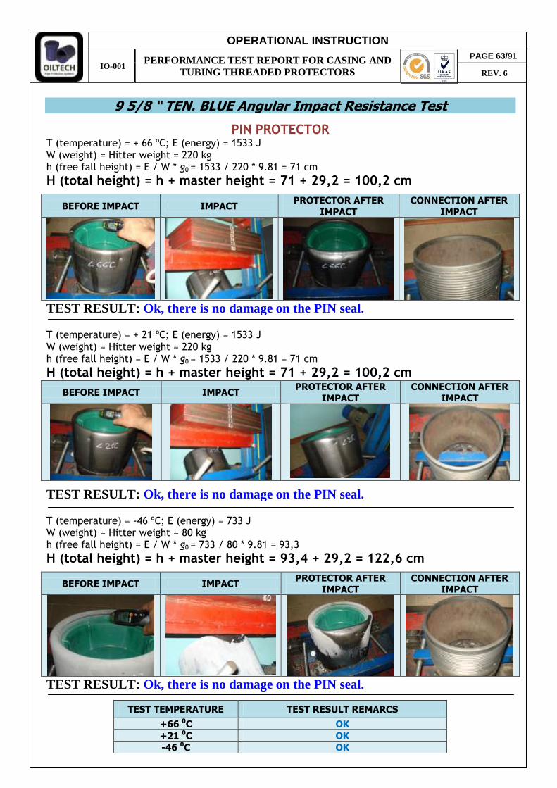
9 5/8 “ TEN. BLUE Angular Impact Resistance Test
PIN PROTECTOR T (temperature) = + 66 ºC; E (energy) = 1533 J W (weight) = Hitter weight = 220 kg h (free fall height) = E / W * g0 = 1533 / 220 * 9.81 = 71 cm
H (total height) = h + master height = 71 + 29,2 = 100,2 cm
BEFORE IMPACT IMPACT PROTECTOR AFTER
IMPACT
CONNECTION AFTER
IMPACT
TEST RESULT: Ok, there is no damage on the PIN seal. T (temperature) = + 21 ºC; E (energy) = 1533 J W (weight) = Hitter weight = 220 kg h (free fall height) = E / W * g0 = 1533 / 220 * 9.81 = 71 cm
H (total height) = h + master height = 71 + 29,2 = 100,2 cm
BEFORE IMPACT IMPACT PROTECTOR AFTER
IMPACT
CONNECTION AFTER
IMPACT
TEST RESULT: Ok, there is no damage on the PIN seal. T (temperature) = -46 ºC; E (energy) = 733 J W (weight) = Hitter weight = 80 kg h (free fall height) = E / W * g0 = 733 / 80 * 9.81 = 93,3
H (total height) = h + master height = 93,4 + 29,2 = 122,6 cm
BEFORE IMPACT IMPACT PROTECTOR AFTER
IMPACT CONNECTION AFTER
IMPACT
TEST RESULT: Ok, there is no damage on the PIN seal.
TEST TEMPERATURE TEST RESULT REMARCS
+66 0C OK +21 0C OK -46 0C OK
PAGE 63/91
REV. 6

OPERATIONAL INSTRUCTION
IO-001 PERFORMANCE TEST REPORT FOR CASING AND
TUBING THREADED PROTECTORS
BOX PROTECTOR
T (temperature) = + 66 ºC; E (energy) = 1533 J W (weight) = Hitter weight = 220 kg h (free fall height) = E / W * g0 = 1533 / 220 * 9.81 = 71 cm
H (total height) = h + master height = 71 + 30 = 101 cm
BEFORE IMPACT IMPACT PROTECTOR AFTER
IMPACT
CONNECTION AFTER
IMPACT
TEST RESULT: Ok, there is no damage on the BOX connection. T (temperature) = + 21 ºC; E (energy) = 1533 J W (weight) = Hitter weight = 220 kg h (free fall height) = E / W * g0 = 1533 / 220 * 9.81 = 71 cm
H (total height) = h + master height = 71 + 30 = 101 cm
BEFORE IMPACT IMPACT PROTECTOR AFTER
IMPACT CONNECTION AFTER
IMPACT
TEST RESULT: Ok, there is no damage on the BOX connection. T (temperature) = -46 ºC; E (energy) = 733 J W (weight) = Hitter weight = 80 kg h (free fall height) = E / W * g0 = 733 / 80 * 9.81 = 93,4
H (total height) = h + master height = 93,4 + 30 = 123,4 cm
BEFORE IMPACT IMPACT PROTECTOR AFTER
IMPACT CONNECTION AFTER
IMPACT
TEST RESULT: Ok, there is no damage on the BOX connection.
TEST TEMPERATURE TEST RESULT REMARCS
+66 0C OK +21 0C OK -46 0C OK
PAGE 64/91
REV. 6
OPERATIONAL INSTRUCTION
IO-001 PERFORMANCE TEST REPORT FOR CASING AND
TUBING THREADED PROTECTORS
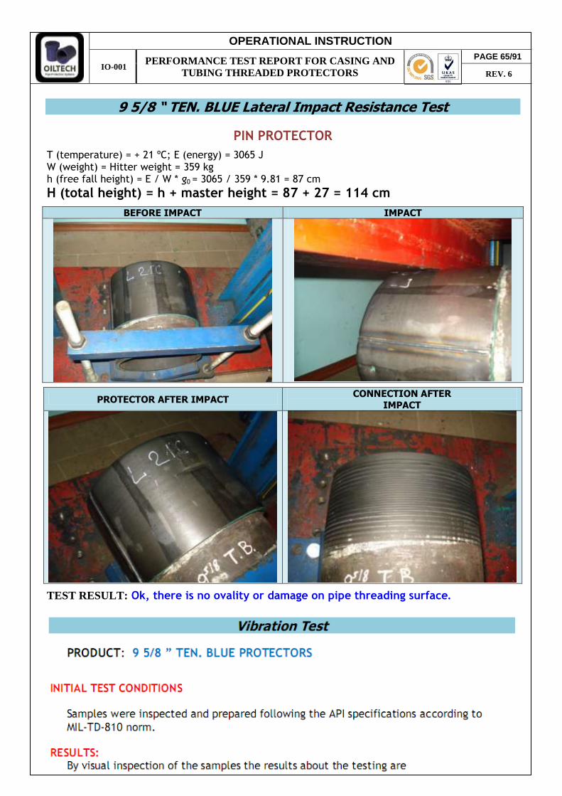
9 5/8 “ TEN. BLUE Lateral Impact Resistance Test
PIN PROTECTOR
T (temperature) = + 21 ºC; E (energy) = 3065 J W (weight) = Hitter weight = 359 kg h (free fall height) = E / W * g0 = 3065 / 359 * 9.81 = 87 cm
H (total height) = h + master height = 87 + 27 = 114 cm
BEFORE IMPACT IMPACT
PROTECTOR AFTER IMPACT CONNECTION AFTER
IMPACT
TEST RESULT: Ok, there is no ovality or damage on pipe threading surface.
PAGE 65/91
REV. 6
OPERATIONAL INSTRUCTION
IO-001 PERFORMANCE TEST REPORT FOR CASING AND
TUBING THREADED PROTECTORS
PAGE 66/91
REV. 6
OPERATIONAL INSTRUCTION
IO-001 PERFORMANCE TEST REPORT FOR CASING AND
TUBING THREADED PROTECTORS
PAGE 67/91
REV. 6

OPERATIONAL INSTRUCTION
IO-001 PERFORMANCE TEST REPORT FOR CASING AND
TUBING THREADED PROTECTORS
Environment / UV Resistance Test
PRODUCT: PRO-C CEL BOX PROTECTORS
INITIAL TEST CONDITIONS Protectors were manufactured and painted with all color types (purple, green, black) used in production. The samples were stored outside on direct UV impact. Four initial states were applied on each type of paint color: 5. Protector cleaned with solvent, after painted, like usually prepared for delivery.
Exposed outside to direct UV rays. (dry) 6. Protector cleaned with solvent and painted, filled with water. Exposed outside to
direct UV rays. (water) 7. Protector not cleaned after pressing process. Painted over oiled surface and exposed
outside to direct UV rays. (Non cleaned) 8. Protector cleaned with solvent, refrigerated at -25C0 and painted over the condensate
metal surface. Exposed outside to direct UV rays. Test period for protector storage - at least one year. Positive result to respect test requirements: no protector damages, paint detaching or color changes are accepted with normal painting applied process. FINAL TEST RESULTS
5. Painted surface changes non essential. Applied paint didn’t detach from steel but only from plastic surface of protector (dry).
6. Paint detach from metal and plastic surface that was kept in water. On metal surface we can see a thin stratum of rush, which didn’t influence the resistance of protector at strikes. (water)
7. Applied paint detach from 3-7% metal surface (base of protector). On other surface it’s very difficult to take out the paint with a steel cut. (non cleaned)
8. Applied paint didn’t detach from metal surface. On plastic surface we can see shrunken paint resulted from temperature and humidity. There is small air bulbs succeeded from
PAGE 68/91
REV. 6
OPERATIONAL INSTRUCTION
IO-001 PERFORMANCE TEST REPORT FOR CASING AND
TUBING THREADED PROTECTORS
condensate steel surface. It’s very difficult to take out the paint with a steel cut from steel surface. (condensate)
CONCLUSION: For all types paint colors was observed the same results for 4 initial test states. In normal cleaning conditions paint protects steel surface from any corrosion during MIN. one year environmental conditions and UV exposal. No blanks damages or deformation was observed. Paint Types are accepted to be used.
PAGE 69/91
REV. 6
OPERATIONAL INSTRUCTION
IO-001 PERFORMANCE TEST REPORT FOR CASING AND
TUBING THREADED PROTECTORS
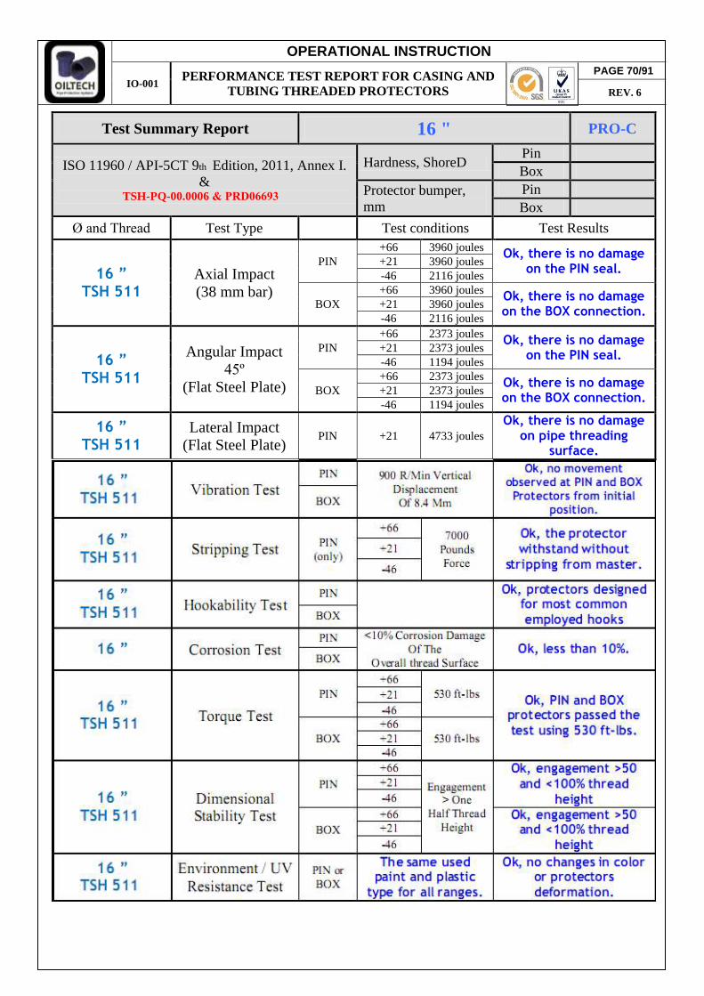
Test Summary Report 16 " PRO-C
ISO 11960 / API-5CT 9th Edition, 2011, Annex I. &
Hardness, ShoreD Pin Box
Protector bumper, mm
Pin Box
Ø and Thread Test Type Test conditions Test Results
16 ” TSH 511
Axial Impact (38 mm bar)
PIN +66 3960 joules
Ok, there is no damage on the PIN seal.
+21 3960 joules -46 2116 joules
BOX +66 3960 joules
Ok, there is no damage on the BOX connection.
+21 3960 joules -46 2116 joules
16 ” TSH 511
Angular Impact 45º
(Flat Steel Plate)
PIN +66 2373 joules
Ok, there is no damage on the PIN seal.
+21 2373 joules -46 1194 joules
BOX +66 2373 joules
Ok, there is no damage on the BOX connection.
+21 2373 joules -46 1194 joules
16 ” TSH 511
Lateral Impact (Flat Steel Plate)
PIN +21 4733 joules Ok, there is no damage
on pipe threading surface.
PAGE 70/91
REV. 6
TSH-PQ-00.0006 & PRD06693

OPERATIONAL INSTRUCTION
IO-001 PERFORMANCE TEST REPORT FOR CASING AND
TUBING THREADED PROTECTORS
16 “ TSH 511 Axial Impact Resistance Test
PIN PROTECTOR
T (temperature) = + 66 ºC; E (energy) = 3960 J W (weight) = Hitter weight + Steel bar weight = 359 + 7 = 366 kg h (free fall height) = E / W * g0 = 3960 / 366 * 9.81 = 110,3 cm
H (total height) = h + master height = 110,3 + 56 = 166,3 cm
BEFORE IMPACT IMPACT PROTECTOR AFTER
IMPACT
CONNECTION AFTER
IMPACT
TEST RESULT: Ok, there is no damage on the PIN seal. T (temperature) = + 21 ºC; E (energy) = 3960 J W (weight) = Hitter weight + Steel bar weight = 359 + 7 = 366 kg h (free fall height) = E / W * g0 = 3960 / 366 * 9.81 = 110,3 cm
H (total height) = h + master height = 110,3 + 56 = 166,3 cm
BEFORE IMPACT IMPACT PROTECTOR AFTER
IMPACT
CONNECTION AFTER
IMPACT
TEST RESULT: Ok, there is no damage on the PIN seal. T (temperature) = -46 ºC; E (energy) = 2116 J W (weight) = Hitter weight + Steel bar weight = 220 + 7 = 227 kg h (free fall height) = E / W * g0 = 2116 / 227 * 9.81 = 95 cm
H (total height) = h + master height = 95 + 56 = 151 cm
BEFORE IMPACT IMPACT PROTECTOR AFTER
IMPACT CONNECTION AFTER
IMPACT
TEST RESULT: Ok, there is no damage on the PIN seal.
TEST TEMPERATURE TEST RESULT REMARCS
+66 0C OK +21 0C OK -46 0C OK
PAGE 71/91
REV. 6

OPERATIONAL INSTRUCTION
IO-001 PERFORMANCE TEST REPORT FOR CASING AND
TUBING THREADED PROTECTORS
BOX PROTECTOR
T (temperature) = + 66 ºC; E (energy) = 3960 J W (weight) = Hitter weight + Steel bar weight = 359 + 7 = 366 kg h (free fall height) = E / W * g0 = 3960 / 366 * 9.81 = 110,3 cm
H (total height) = h + master height = 110,3 + 50 = 166,3 cm
BEFORE IMPACT IMPACT PROTECTOR AFTER
IMPACT
CONNECTION AFTER
IMPACT
TEST RESULT: Ok, there is no damage on the BOX connection. T (temperature) = + 21 ºC; E (energy) = 3960 J W (weight) = Hitter weight + Steel bar weight = 359 + 7 = 366 kg h (free fall height) = E / W * g0 = 3960 / 366 * 9.81 = 110,3 cm
H (total height) = h + master height = 110,3 + 50 = 166,3 cm
BEFORE IMPACT IMPACT PROTECTOR AFTER
IMPACT CONNECTION AFTER
IMPACT
TEST RESULT: Ok, there is no damage on the BOX connection. T (temperature) = -46 ºC; E (energy) = 2116 J W (weight) = Hitter weight + Steel bar weight = 220 + 7 = 227 kg h (free fall height) = E / W * g0 = 2116 / 227 * 9.81 = 95 cm
H (total height) = h + master height = 95 + 50 = 145 cm
BEFORE IMPACT IMPACT PROTECTOR AFTER
IMPACT CONNECTION AFTER
IMPACT
TEST RESULT: Ok, there is no damage on the BOX connection.
TEST TEMPERATURE TEST RESULT REMARCS
+66 0C OK +21 0C OK -46 0C OK
PAGE 72/91
REV. 6
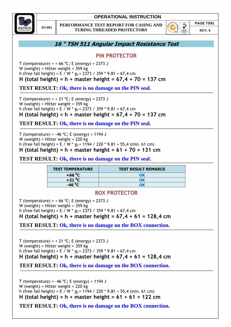
OPERATIONAL INSTRUCTION
IO-001 PERFORMANCE TEST REPORT FOR CASING AND
TUBING THREADED PROTECTORS
16 “ TSH 511 Angular Impact Resistance Test
PIN PROTECTOR
T (temperature) = + 66 ºC; E (energy) = 2373 J W (weight) = Hitter weight = 359 kg h (free fall height) = E / W * g0 = 2373 / 359 * 9.81 = 67,4 cm
H (total height) = h + master height = 67,4 + 70 = 137 cm
TEST RESULT: Ok, there is no damage on the PIN seal. T (temperature) = + 21 ºC; E (energy) = 2373 J W (weight) = Hitter weight = 359 kg h (free fall height) = E / W * g0 = 2373 / 359 * 9.81 = 67,4 cm
H (total height) = h + master height = 67,4 + 70 = 137 cm
TEST RESULT: Ok, there is no damage on the PIN seal. T (temperature) = -46 ºC; E (energy) = 1194 J W (weight) = Hitter weight = 220 kg h (free fall height) = E / W * g0 = 1194 / 220 * 9.81 = 55,4 (min. 61 cm)
H (total height) = h + master height = 61 + 70 = 131 cm
TEST RESULT: Ok, there is no damage on the PIN seal.
BOX PROTECTOR
T (temperature) = + 66 ºC; E (energy) = 2373 J W (weight) = Hitter weight = 359 kg h (free fall height) = E / W * g0 = 2373 / 359 * 9.81 = 67,4 cm
H (total height) = h + master height = 67,4 + 61 = 128,4 cm
TEST RESULT: Ok, there is no damage on the BOX connection. T (temperature) = + 21 ºC; E (energy) = 2373 J W (weight) = Hitter weight = 359 kg h (free fall height) = E / W * g0 = 2373 / 359 * 9.81 = 67,4 cm
H (total height) = h + master height = 67,4 + 61 = 128,4 cm
TEST RESULT: Ok, there is no damage on the BOX connection. T (temperature) = -46 ºC; E (energy) = 1194 J W (weight) = Hitter weight = 220 kg h (free fall height) = E / W * g0 = 1194 / 220 * 9.81 = 55,4 (min. 61 cm)
H (total height) = h + master height = 61 + 61 = 122 cm
TEST RESULT: Ok, there is no damage on the BOX connection.
TEST TEMPERATURE TEST RESULT REMARCS
+66 0C OK +21 0C OK -46 0C OK
PAGE 73/91
REV. 6
OPERATIONAL INSTRUCTION
IO-001 PERFORMANCE TEST REPORT FOR CASING AND
TUBING THREADED PROTECTORS
TEST TEMPERATURE TEST RESULT REMARCS
+66 0C OK +21 0C OK -46 0C OK
PAGE 74/91
REV. 6

OPERATIONAL INSTRUCTION
IO-001 PERFORMANCE TEST REPORT FOR CASING AND
TUBING THREADED PROTECTORS
PAGE 75/91
REV. 6

OPERATIONAL INSTRUCTION
IO-001 PERFORMANCE TEST REPORT FOR CASING AND
TUBING THREADED PROTECTORS
PAGE 76/91
REV. 6
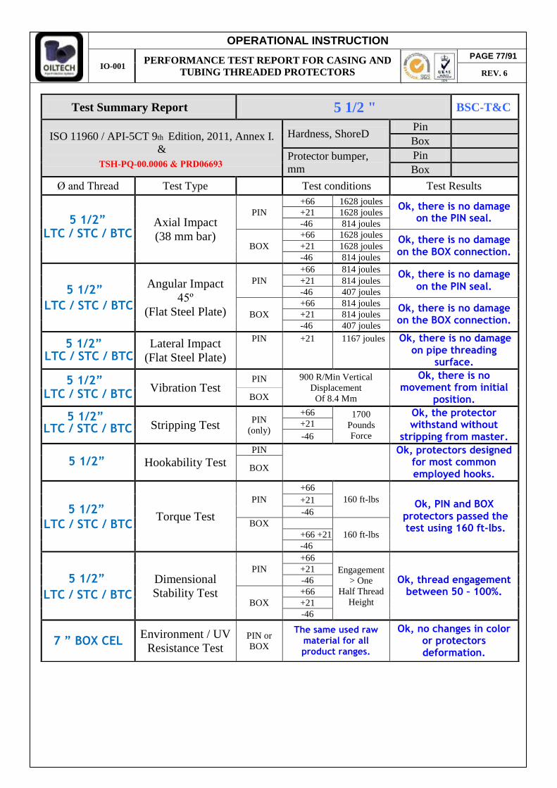
OPERATIONAL INSTRUCTION
IO-001 PERFORMANCE TEST REPORT FOR CASING AND
TUBING THREADED PROTECTORS
ISO 11960 / API-5CT 9th Edition, 2011, Annex I. &
Hardness, ShoreD Pin Box
Protector bumper, mm
Pin Box
Axial Impact (38 mm bar)
on the PIN seal.
BOX on the BOX connection.
Angular Impact 45º
(Flat Steel Plate)
PIN on the PIN seal.
BOX on the BOX connection.
Lateral Impact (Flat Steel Plate)
on pipe threading surface.
Vibration Test PIN 900 R/Min Vertical
Displacement Of 8.4 Mm
Ok, there is no movement from initial
position. BOX
Stripping Test PIN (only)
Pounds Force
Ok, the protector withstand without
stripping from master. +21 -46
Hookability Test PIN
Ok, protectors designed
for most common employed hooks.
BOX
Torque Test
PIN +66 +21 -46
Dimensional Stability Test
PIN +66
Engagement > One
Half Thread Height
Ok, thread engagement between 50 – 100%.
+21 -46
BOX +66 +21 -46
7 ” BOX CEL Environment / UV Resistance Test
PIN or BOX
The same used raw material for all product ranges.
Ok, no changes in color or protectors deformation.
5 1/2 "
5 1/2”
Test Summary Report BSC-T&C
LTC / STC / BTC
LTC / STC / BTC
5 1/2”
5 1/2” LTC / STC / BTC
5 1/2”
5 1/2”
5 1/2”
5 1/2”
5 1/2”
LTC / STC / BTC
LTC / STC / BTC
LTC / STC / BTC
Ø and Thread Test Type Test conditions Test Results
PIN +66 1628 joules
Ok, there is no damage+21 1628 joules -46 814 joules +66 1628 joules
Ok, there is no damage +21 1628 joules
-46 814 joules +66 814 joules
Ok, there is no damage +21 814 joules
-46 407 joules +66 814 joules
Ok, there is no damage +21 814 joules
-46 407 joules PIN +21 1167 joules Ok, there is no damage
+66 1700
160 ft-lbs Ok, PIN and BOX
BOX +66 +21 160 ft-lbs -46
protectors passed the test using 160 ft-lbs.
LTC / STC / BTC
PAGE 77/91
REV. 6
TSH-PQ-00.0006 & PRD06693

OPERATIONAL INSTRUCTION
IO-001 PERFORMANCE TEST REPORT FOR CASING AND
TUBING THREADED PROTECTORS
PIN PROTECTOR
BEFORE IMPACT IMPACT PROTECTOR AFTER
IMPACT
CONNECTION AFTER
IMPACT
TEST RESULT: Ok, there is no damage on the PIN seal.
TEST RESULT: Ok, there is no damage on the PIN seal.
BEFORE IMPACT IMPACT PROTECTOR AFTER
IMPACT
CONNECTION AFTER
IMPACT
TEST RESULT: Ok, there is no damage on the PIN seal.
TEST TEMPERATURE TEST RESULT REMARCS
+66 0C OK +21 0C OK -46 0C OK
5 1/2 “ LTC / BTC Axial Impact Resistance Test
T (temperature) = + 66 ºC; E (energy) = 1628 J W (weight) = Hitter weight + Steel bar weight = 220 + 7 = 227 kg h (free fall height) = E / W * g0 = 1628 / 227 * 9.81 = 73,1 cm
H (total height) = h + master height = 73,1 + 30 = 103,1 cm
H (total height) = h + master height = 73,1 + 30 = 103,1 cm
T (temperature) = + 21 ºC; E (energy) = 1628 J W (weight) = Hitter weight + Steel bar weight = 220 + 7 = 227 kg h (free fall height) = E / W * g0 = 1628 / 227 * 9.81 = 73,1 cm
H (total height) = h + master height = 60 + 30 = 90 cm
T (temperature) = -46 ºC; E (energy) = 814 J W (weight) = Hitter weight + Steel bar weight = 136 + 7 = 143 kg h (free fall height) = E / W * g0 = 814 / 143 * 9.81 = 58 cm
PAGE 78/91
REV. 6
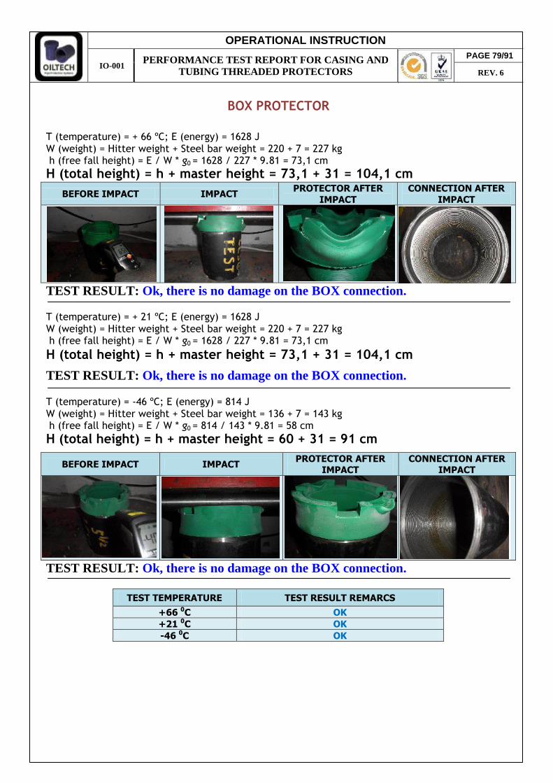
OPERATIONAL INSTRUCTION
IO-001 PERFORMANCE TEST REPORT FOR CASING AND
TUBING THREADED PROTECTORS
BOX PROTECTOR
BEFORE IMPACT IMPACT PROTECTOR AFTER
IMPACT
CONNECTION AFTER
IMPACT
TEST RESULT: Ok, there is no damage on the BOX connection.
TEST RESULT: Ok, there is no damage on the BOX connection.
BEFORE IMPACT IMPACT PROTECTOR AFTER
IMPACT CONNECTION AFTER
IMPACT
TEST RESULT: Ok, there is no damage on the BOX connection.
TEST TEMPERATURE TEST RESULT REMARCS
+66 0C OK +21 0C OK -46 0C OK
T (temperature) = + 66 ºC; E (energy) = 1628 J W (weight) = Hitter weight + Steel bar weight = 220 + 7 = 227 kg h (free fall height) = E / W * g0 = 1628 / 227 * 9.81 = 73,1 cm
H (total height) = h + master height = 73,1 + 31 = 104,1 cm
T (temperature) = + 21 ºC; E (energy) = 1628 J W (weight) = Hitter weight + Steel bar weight = 220 + 7 = 227 kg h (free fall height) = E / W * g0 = 1628 / 227 * 9.81 = 73,1 cm
H (total height) = h + master height = 73,1 + 31 = 104,1 cm
T (temperature) = -46 ºC; E (energy) = 814 J W (weight) = Hitter weight + Steel bar weight = 136 + 7 = 143 kg h (free fall height) = E / W * g0 = 814 / 143 * 9.81 = 58 cm
H (total height) = h + master height = 60 + 31 = 91 cm
PAGE 79/91
REV. 6
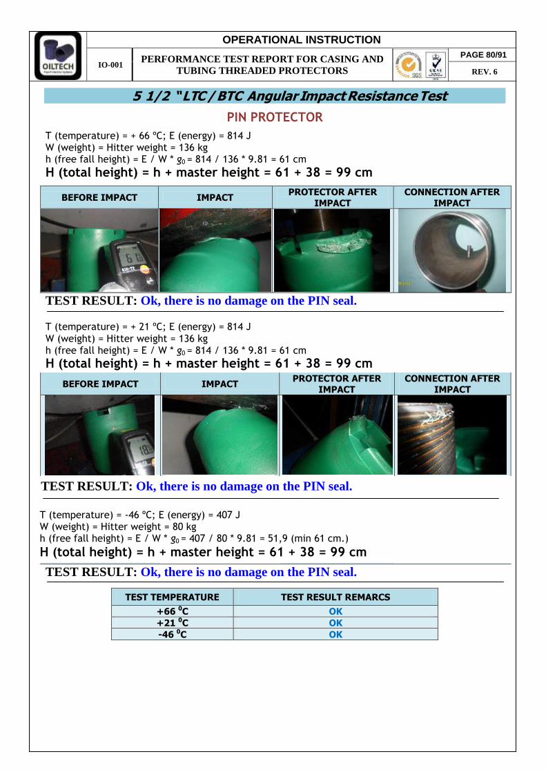
OPERATIONAL INSTRUCTION
IO-001 PERFORMANCE TEST REPORT FOR CASING AND
TUBING THREADED PROTECTORS
PIN PROTECTOR
BEFORE IMPACT IMPACT PROTECTOR AFTER
IMPACT
CONNECTION AFTER
IMPACT
TEST RESULT: Ok, there is no damage on the PIN seal.
TEST RESULT: Ok, there is no damage on the PIN seal. T (temperature) = -46 ºC; E (energy) = 407 J W (weight) = Hitter weight = 80 kg h (free fall height) = E / W * g0 = 407 / 80 * 9.81 = 51,9 (min 61 cm.)
BEFORE IMPACT IMPACT PROTECTOR AFTER
IMPACT CONNECTION AFTER
IMPACT
TEST RESULT: Ok, there is no damage on the PIN seal.
TEST TEMPERATURE TEST RESULT REMARCS
+66 0C OK +21 0C OK -46 0C OK
5 1/2 “ LTC / BTC Angular Impact Resistance Test
T (temperature) = + 66 ºC; E (energy) = 814 J W (weight) = Hitter weight = 136 kg h (free fall height) = E / W * g0 = 814 / 136 * 9.81 = 61 cm
H (total height) = h + master height = 61 + 38 = 99 cm
T (temperature) = + 21 ºC; E (energy) = 814 J
W (weight) = Hitter weight = 136 kg h (free fall height) = E / W * g0 = 814 / 136 * 9.81 = 61 cm
H (total height) = h + master height = 61 + 38 = 99 cm
H (total height) = h + master height = 61 + 38 = 99 cm
PAGE 80/91
REV. 6
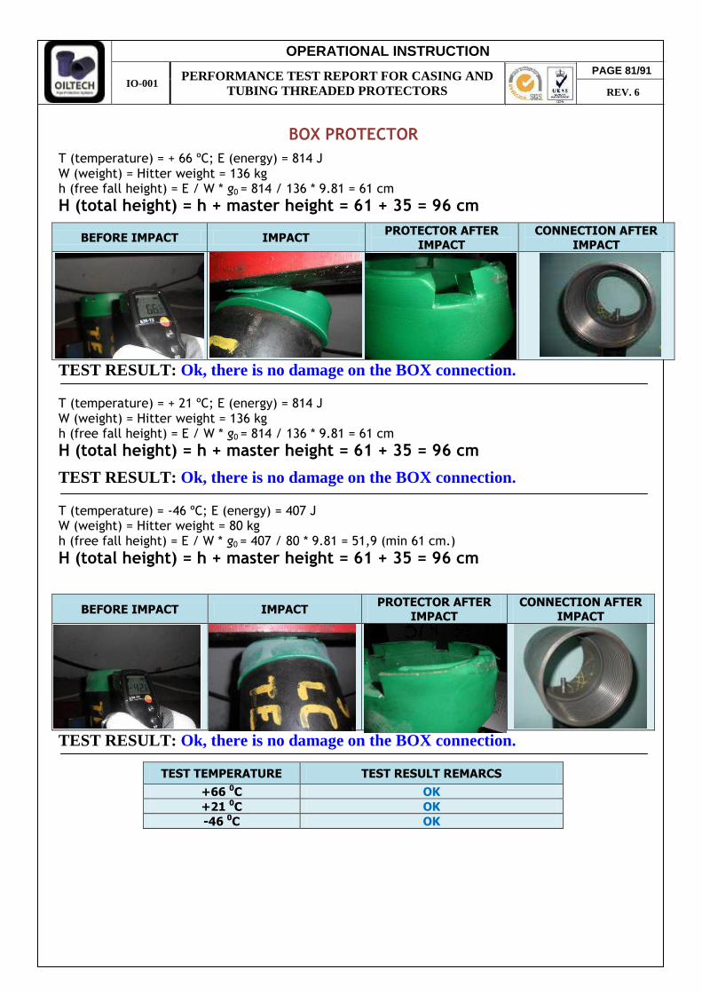
OPERATIONAL INSTRUCTION
IO-001 PERFORMANCE TEST REPORT FOR CASING AND
TUBING THREADED PROTECTORS
BOX PROTECTOR
IMPACT
CONNECTION AFTER
IMPACT
TEST RESULT: Ok, there is no damage on the BOX connection.
T (temperature) = -46 ºC; E (energy) = 407 J W (weight) = Hitter weight = 80 kg h (free fall height) = E / W * g0 = 407 / 80 * 9.81 = 51,9 (min 61 cm.)
BEFORE IMPACT IMPACT PROTECTOR AFTER
IMPACT
CONNECTION AFTER
IMPACT
TEST RESULT: Ok, there is no damage on the BOX connection.
TEST TEMPERATURE TEST RESULT REMARCS
+66 0C OK +21 0C OK -46 0C OK
T (temperature) = + 66 ºC; E (energy) = 814 J W (weight) = Hitter weight = 136 kg h (free fall height) = E / W * g0 = 814 / 136 * 9.81 = 61 cm
H (total height) = h + master height = 61 + 35 = 96 cm
T (temperature) = + 21 ºC; E (energy) = 814 J W (weight) = Hitter weight = 136 kg h (free fall height) = E / W * g0 = 814 / 136 * 9.81 = 61 cm
H (total height) = h + master height = 61 + 35 = 96 cm
H (total height) = h + master height = 61 + 35 = 96 cm
BEFORE IMPACT IMPACT PROTECTOR AFTER
TEST RESULT: Ok, there is no damage on the BOX connection.
PAGE 81/91
REV. 6

OPERATIONAL INSTRUCTION
IO-001 PERFORMANCE TEST REPORT FOR CASING AND
TUBING THREADED PROTECTORS
PIN PROTECTOR
TEST RESULT: Ok, there is no damage on pipe threading surface.
Vibration Test
INITIAL TEST CONDITIONS
Samples were inspected and prepared following the API specifications according to MIL-TD-810 norm.
RESULTS: Protectors didn’t move from their initial position. Protectors didn’t have damages and residues over the thread’s connection. Also, kept the torque which was given from initial.
Stripping Test
PRODUCT: 5 1/2 ” LTC / BTC PIN PROTECTOR Fax (requested according TSH-PQ-00.0006 procedure) = 1700 lbs Where: F = Axial force (pounds force)
PRODUCT: 5 1/2 ” LTC / BTC PROTECTOR
5 1/2 “ LTC / BTC Lateral Impact Resistance Test
T (temperature) = + 21 ºC; E (energy) = 1167 J
W (weight) = Hitter weight = 220 kg h (free fall height) = E / W * g0 = 1167 / 220 * 9.81 = 54 cm
H (total height) = h + master height = 54 + 22 = 76 cm
PAGE 82/91
REV. 6
type UNI4395 and DIN 15401.
According to the general specification the product of the Line BSC-C and BSC-T protectors
Hookability (Liftability) Test
L (5 1/2") = 1.5 * 45 (ft) * W (lbs/ft) = 1.5* 45 * 23 = 1552 (lbs) = 704 kgf
the shape of the liftable side is conform to most common hooks employed in the rigs. The test has been performed on 5 ½” and 9 5/8” sizes with the appropriate range of hooks
FINAL TEST RESULTS Ok, For pin protector was applied 720 kgf, for box - 880 kgf. Pipe and coupling seal faces and thread no dented and not affected (see pictures bellow).
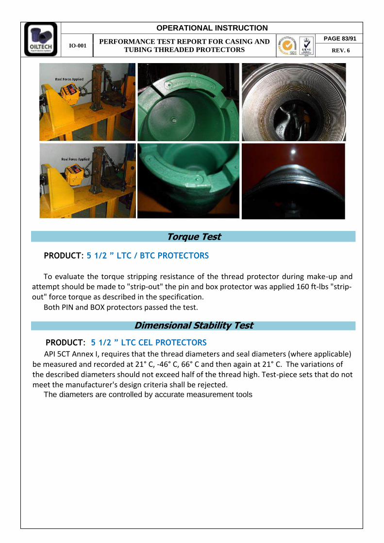
OPERATIONAL INSTRUCTION
IO-001 PERFORMANCE TEST REPORT FOR CASING AND
TUBING THREADED PROTECTORS
Torque Test
To evaluate the torque stripping resistance of the thread protector during make-up and
Both PIN and BOX protectors passed the test.
Dimensional Stability Test
API 5CT Annex I, requires that the thread diameters and seal diameters (where applicable) be measured and recorded at 21° C, -46° C, 66° C and then again at 21° C. The variations of the described diameters should not exceed half of the thread high. Test-piece sets that do not meet the manufacturer's design criteria shall be rejected.
PRODUCT: 5 1/2 ” LTC / BTC PROTECTORS
PAGE 83/91
REV. 6
PRODUCT: 5 1/2 ” LTC CEL PROTECTORS
The diameters are controlled by accurate measurement tools
attempt should be made to "strip-out" the pin and box protector was applied 160 ft-lbs "strip-out" force torque as described in the specification.
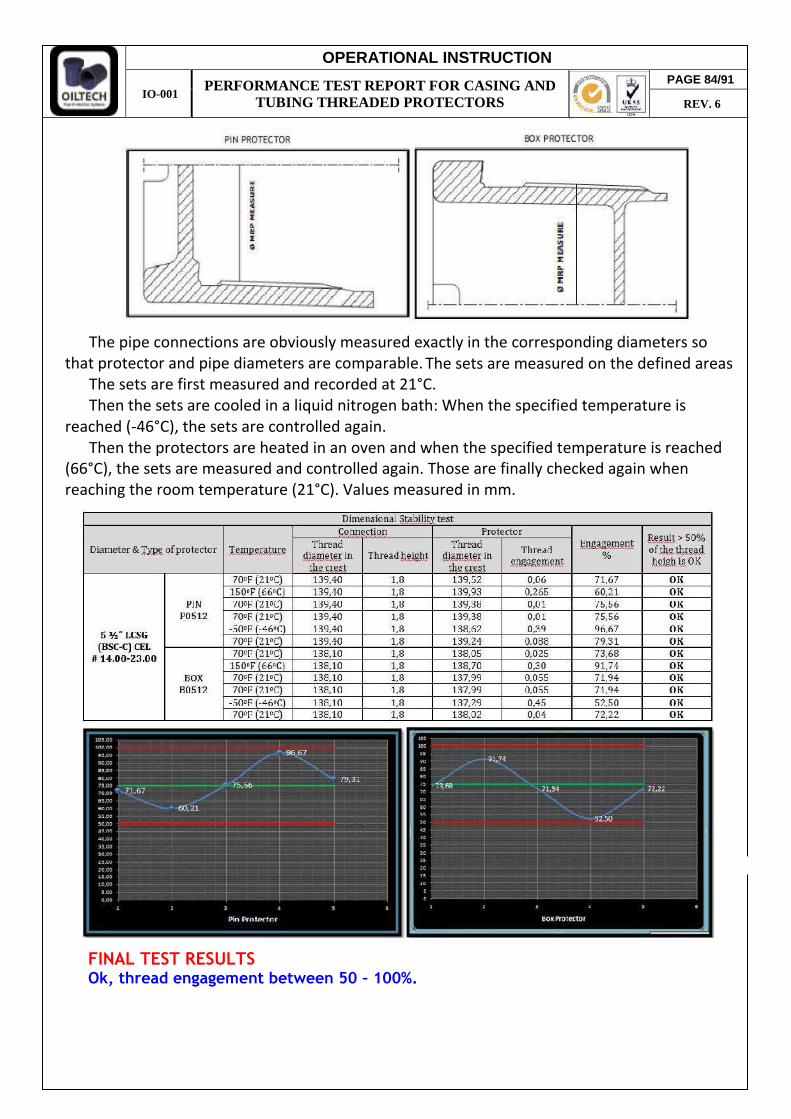
OPERATIONAL INSTRUCTION
IO-001 PERFORMANCE TEST REPORT FOR CASING AND
TUBING THREADED PROTECTORS
The pipe connections are obviously measured exactly in the corresponding diameters so that protector and pipe diameters are comparable.
The sets are first measured and recorded at 21°C. Then the sets are cooled in a liquid nitrogen bath: When the specified temperature is
reached (-46°C), the sets are controlled again. Then the protectors are heated in an oven and when the specified temperature is reached
PAGE 84/91
REV. 6
The sets are measured on the defined areas
(66°C), the sets are measured and controlled again. Those are finally checked again when reaching the room temperature (21°C). Values measured in mm.
FINAL TEST RESULTS Ok, thread engagement between 50 – 100%.

OPERATIONAL INSTRUCTION
IO-001 PERFORMANCE TEST REPORT FOR CASING AND
TUBING THREADED PROTECTORS
Hardness, ShoreD Pin Box
Protector bumper, mm
Pin Box
Ø and Thread Test Type Test conditions Test Results
Axial Impact (38 mm bar)
PIN +66 1763 joules
Ok, there is no damage on the PIN seal.
+21 1763 joules -46 882 joules
BOX +66 1763 joules
Ok, there is no damage on the BOX connection.
+21 1763 joules -46 882 joules
Angular Impact 45º
(Flat Steel Plate)
PIN +66 1058 joules
Ok, there is no damage on the PIN seal.
+21 1058 joules -46 407 joules
BOX +66 1058 joules
Ok, there is no damage on the BOX connection.
+21 1058 joules -46 407 joules
Lateral Impact (Flat Steel Plate)
PIN +21 2116 joules Ok, there is no damage
on pipe threading surface.
PIN 900 R/Min Vertical Displacement
Of 8.4 Mm
Ok, there is no movement from initial
position. BOX
PIN (only)
+66 3100 Pounds Force
Ok, the protector withstand without
stripping from master. +21 -46
PIN
Ok, protectors designed for most common employed hooks.
BOX
PIN +66
240 ft-lbs Ok, PIN and BOX
protectors passed the test using 240 ft-lbs.
+21 -46
BOX +66
240 ft-lbs +21 -46
Dimensional Stability Test
PIN +66
Engagement > One
Half Thread Height
Ok, thread engagement between 50 – 100%.
+21 -46
BOX +66 +21 -46
5 ½ ” PIN CEL 7 ” BOX CEL
Environment / UV Resistance Test
PIN or BOX
The same used raw material for all product ranges.
Ok, no changes in color or protectors deformation.
ISO 11960 / API-5CT 9th Edition, 2011, Annex I. &
Test Summary Report 7 5/8 " BSC-C
7 5/8 ”
LCSG/BCSG
7 5/8 ”
LCSG/BCSG
7 5/8 ”
LCSG/BCSG
Vibration Test
Stripping Test
Hookability Test
Torque Test
7 5/8 ”
LCSG/BCSG
7 5/8 ”
LCSG/BCSG
7 5/8 ”
LCSG/BCSG
7 5/8 ”
LCSG/BCSG
7 5/8 ”
LCSG/BCSG
PAGE 85/91
REV. 6
TSH-PQ-00.0006 & PRD06693
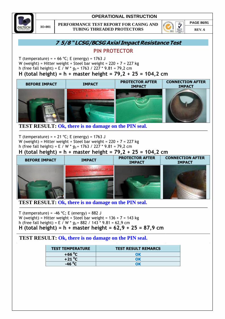
OPERATIONAL INSTRUCTION
IO-001 PERFORMANCE TEST REPORT FOR CASING AND
TUBING THREADED PROTECTORS
PIN PROTECTOR
T (temperature) = + 66 ºC; E (energy) = 1763 J W (weight) = Hitter weight + Steel bar weight = 220 + 7 = 227 kg h (free fall height) = E / W * g0 = 1763 / 227 * 9.81 = 79,2 cm
BEFORE IMPACT IMPACT PROTECTOR AFTER
IMPACT CONNECTION AFTER
IMPACT
TEST RESULT: Ok, there is no damage on the PIN seal. T (temperature) = + 21 ºC; E (energy) = 1763 J W (weight) = Hitter weight + Steel bar weight = 220 + 7 = 227 kg h (free fall height) = E / W * g0 = 1763 / 227 * 9.81 = 79,2 cm
BEFORE IMPACT IMPACT PROTECTOR AFTER
IMPACT CONNECTION AFTER
IMPACT
TEST RESULT: Ok, there is no damage on the PIN seal. T (temperature) = -46 ºC; E (energy) = 882 J W (weight) = Hitter weight + Steel bar weight = 136 + 7 = 143 kg h (free fall height) = E / W * g0 = 882 / 143 * 9.81 = 62,9 cm
TEST TEMPERATURE TEST RESULT REMARCS
+66 0C OK +21 0C OK -46 0C OK
7 5/8 “ LCSG/BCSG Axial Impact Resistance Test
H (total height) = h + master height = 79,2 + 25 = 104,2 cm
H (total height) = h + master height = 79,2 + 25 = 104,2 cm
TEST RESULT: Ok, there is no damage on the PIN seal.
PAGE 86/91
REV. 6
H (total height) = h + master height = 62,9 + 25 = 87,9 cm
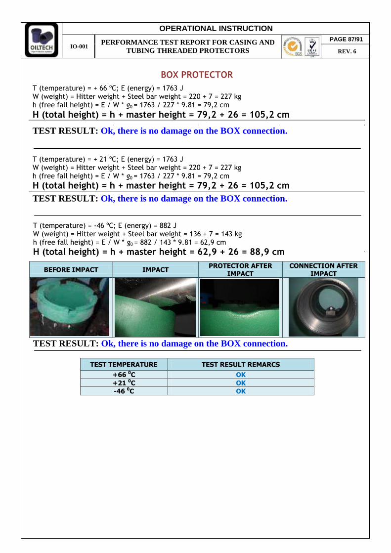
OPERATIONAL INSTRUCTION
IO-001 PERFORMANCE TEST REPORT FOR CASING AND
TUBING THREADED PROTECTORS
BOX PROTECTOR
TEST RESULT: Ok, there is no damage on the BOX connection.
T (temperature) = + 21 ºC; E (energy) = 1763 J W (weight) = Hitter weight + Steel bar weight = 220 + 7 = 227 kg h (free fall height) = E / W * g0 = 1763 / 227 * 9.81 = 79,2 cm
TEST RESULT: Ok, there is no damage on the BOX connection.
T (temperature) = -46 ºC; E (energy) = 882 J W (weight) = Hitter weight + Steel bar weight = 136 + 7 = 143 kg h (free fall height) = E / W * g0 = 882 / 143 * 9.81 = 62,9 cm
BEFORE IMPACT IMPACT PROTECTOR AFTER
IMPACT
CONNECTION AFTER
IMPACT
TEST RESULT: Ok, there is no damage on the BOX connection.
TEST TEMPERATURE TEST RESULT REMARCS
+66 0C OK +21 0C OK -46 0C OK
H (total height) = h + master height = 79,2 + 26 = 105,2 cm
H (total height) = h + master height = 79,2 + 26 = 105,2 cm
H (total height) = h + master height = 62,9 + 26 = 88,9 cm
T (temperature) = + 66 ºC; E (energy) = 1763 J W (weight) = Hitter weight + Steel bar weight = 220 + 7 = 227 kg h (free fall height) = E / W * g0 = 1763 / 227 * 9.81 = 79,2 cm
PAGE 87/91
REV. 6

OPERATIONAL INSTRUCTION
IO-001 PERFORMANCE TEST REPORT FOR CASING AND
TUBING THREADED PROTECTORS
PIN PROTECTOR
T (temperature) = + 66 ºC; E (energy) = 1058 J W (weight) = Hitter weight = 136 kg h (free fall height) = E / W * g0 = 1058 / 136 * 9.81 = 79,3 cm
BEFORE IMPACT IMPACT PROTECTOR AFTER
IMPACT CONNECTION AFTER
IMPACT
TEST RESULT: Ok, there is no damage on the PIN seal.
TEST RESULT: Ok, there is no damage on the PIN seal.
T (temperature) = -46 ºC; E (energy) = 407 J W (weight) = Hitter weight = 80 kg h (free fall height) = E / W * g0 = 407 / 80 * 9.81 = 51,9 (min 61 cm.)
TEST RESULT: Ok, there is no damage on the PIN seal.
TEST TEMPERATURE TEST RESULT REMARCS
+66 0C OK +21 0C OK -46 0C OK
7 5/8 “ LSCG/BCSG Angular Impact Resistance Test
H (total height) = h + master height = 79,3 + 33 = 112,3 cm
T (temperature) = + 21 ºC; E (energy) = 1058 J W (weight) = Hitter weight = 136 kg h (free fall height) = E / W * g0 = 1058 / 136 * 9.81 = 79,3 cm
H (total height) = h + master height = 79,3 + 33 = 112,3 cm
H (total height) = h + master height = 61 + 33 = 94 cm
PAGE 88/91
REV. 6
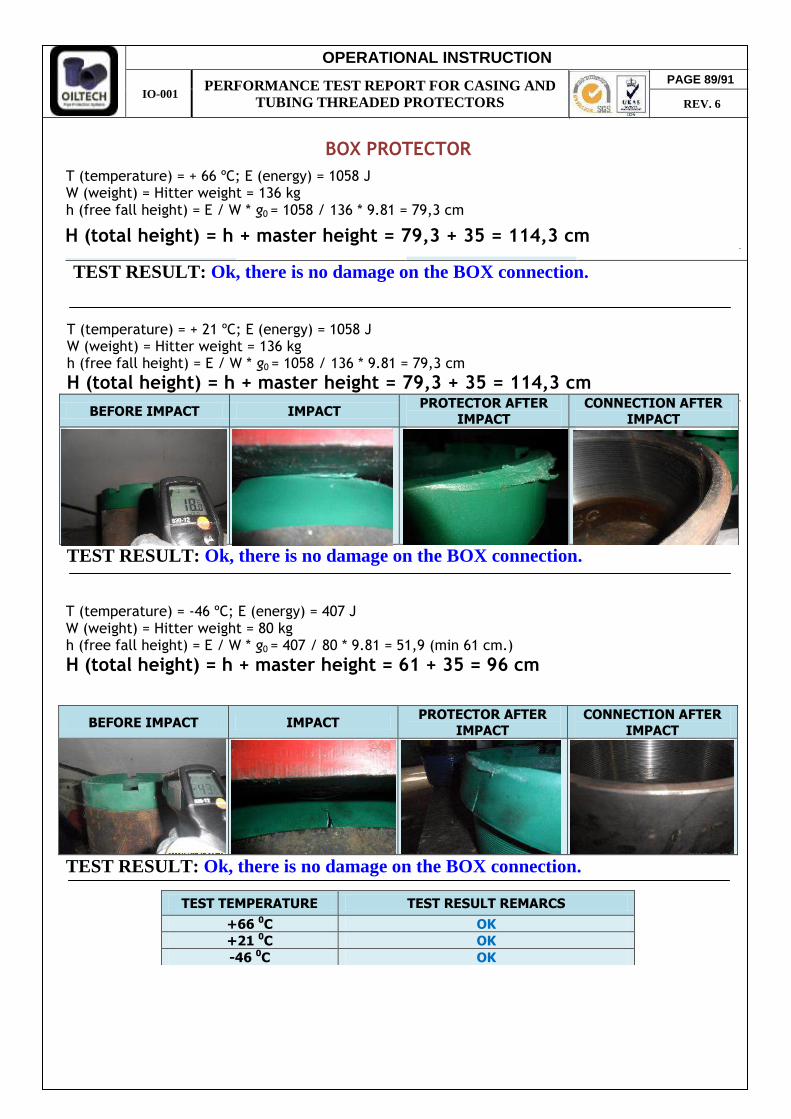
OPERATIONAL INSTRUCTION
IO-001 PERFORMANCE TEST REPORT FOR CASING AND
TUBING THREADED PROTECTORS
BOX PROTECTOR
T (temperature) = + 66 ºC; E (energy) = 1058 J W (weight) = Hitter weight = 136 kg h (free fall height) = E / W * g0 = 1058 / 136 * 9.81 = 79,3 cm
TEST RESULT: Ok, there is no damage on the BOX connection.
T (temperature) = + 21 ºC; E (energy) = 1058 J W (weight) = Hitter weight = 136 kg h (free fall height) = E / W * g0 = 1058 / 136 * 9.81 = 79,3 cm
BEFORE IMPACT IMPACT PROTECTOR AFTER
IMPACT
CONNECTION AFTER
IMPACT
TEST RESULT: Ok, there is no damage on the BOX connection.
T (temperature) = -46 ºC; E (energy) = 407 J W (weight) = Hitter weight = 80 kg h (free fall height) = E / W * g0 = 407 / 80 * 9.81 = 51,9 (min 61 cm.)
BEFORE IMPACT IMPACT PROTECTOR AFTER
IMPACT
CONNECTION AFTER
IMPACT
TEST RESULT: Ok, there is no damage on the BOX connection.
TEST TEMPERATURE TEST RESULT REMARCS
+66 0C OK +21 0C OK -46 0C OK
H (total height) = h + master height = 79,3 + 35 = 114,3 cm
H (total height) = h + master height = 61 + 35 = 96 cm
H (total height) = h + master height = 79,3 + 35 = 114,3 cm
PAGE 89/91
REV. 6
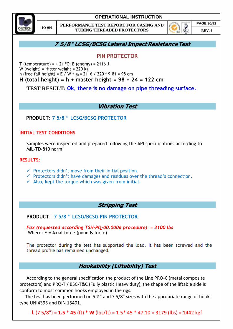
OPERATIONAL INSTRUCTION
IO-001 PERFORMANCE TEST REPORT FOR CASING AND
TUBING THREADED PROTECTORS
PIN PROTECTOR
T (temperature) = + 21 ºC; E (energy) = 2116 J W (weight) = Hitter weight = 220 kg h (free fall height) = E / W * g0 = 2116 / 220 * 9.81 = 98 cm
TEST RESULT: Ok, there is no damage on pipe threading surface.
Vibration Test
INITIAL TEST CONDITIONS
Samples were inspected and prepared following the API specifications according to MIL-TD-810 norm.
RESULTS: Protectors didn’t move from their initial position. Protectors didn’t have damages and residues over the thread’s connection. Also, kept the torque which was given from initial.
Stripping Test
Hookability (Liftability) Test
According to the general specification the product of the Line PRO-C (metal composite
type UNI4395 and DIN 15401.
7 5/8 “ LCSG/BCSG Lateral Impact Resistance Test
H (total height) = h + master height = 98 + 24 = 122 cm
PRODUCT: 7 5/8 ” LCSG/BCSG PROTECTOR
PRODUCT: 7 5/8 ” LCSG/BCSG PIN PROTECTOR Fax (requested according TSH-PQ-00.0006 procedure) = 3100 lbs Where: F = Axial force (pounds force)
PAGE 90/91
REV. 6
L (7 5/8") = 1.5 * 45 (ft) * W (lbs/ft) = 1.5* 45 * 47.10 = 3179 (lbs) = 1442 kgf
protectors) and PRO-T / BSC-T&C (Fully plastic Heavy duty), the shape of the liftable side is conform to most common hooks employed in the rigs. The test has been performed on 5 ½” and 7 5/8” sizes with the appropriate range of hooks
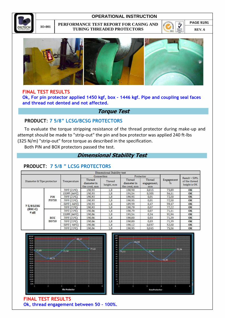
OPERATIONAL INSTRUCTION
IO-001 PERFORMANCE TEST REPORT FOR CASING AND
TUBING THREADED PROTECTORS
Torque Test
To evaluate the torque stripping resistance of the thread protector during make-up and
attempt should be made to "strip-out" the pin and box protector was applied 240 ft-lbs (325 N/m) "strip-out" force torque as described in the specification.
Both PIN and BOX protectors passed the test.
Dimensional Stability Test
FINAL TEST RESULTS Ok, thread engagement between 50 – 100%.
PRODUCT: 7 5/8” LCSG/BCSG PROTECTORS
PAGE 91/91
REV. 6
PRODUCT: 7 5/8 ” LCSG PROTECTORS
and thread not dented and not affected.
FINAL TEST RESULTS Ok, For pin protector applied 1450 kgf, box - 1446 kgf. Pipe and coupling seal faces