Embed Size (px)
Citation preview

Project Brief
This 32-storey commercial tower, located at Wan Chaidistrict of Hong Kong, will become an iconic building in thecommercial and business district when completed.
The complexity of the project, with its unique building form,an inverted pyramid, limited site access and working space,places an uncommonly strong emphasis on temporary workdesign and safety & health planning.
Contract Start Date: November 2016Contract Finish Date: February 2019Contraction Period: 815 daysContract Sum: approx.1000 millionConstruction Floor Area: about 40,000m2Number of storey: 32Carpark Floor: 1-storey at B/FPodium Floor: 4-story between G/F and 3/FMEP Floor: 6-storey between 5/F and 10/FOffice Floor: 22-storey between 11/F and 30/F
Proposed Office Development at 1 Hennessy Road, Hong KongTEMPORARY WORKS EXCELLENCE AWARD 2017
Page 1
Client: 華懋集團Chinachem Group
Architect: 劉榮廣伍振民建築師事務所(香港)有限公司Dennis Lau & Ng Chun Man Architects & Engineers (HK) Ltd.
Structure Engineer:奧雅納工程顧問公司Ove Arup & Partners Hong Kong Limited
BS Engineer: 澧信機電工程顧問J. Roger Preston Limited
Main Contractor: 華營建築有限公司CR Construction Company Limited
Section of Building
Project Rendering
Building Structural System
The inverted pyramid structure is located between 7/F and 10/Fwhere 8 nos. of inclined mega size columns are connected to 7/Fcentral core wall at one end and 10/F 3m deep tension beam atthe other.
Traditional R.C. column-beam design is adopted between G/Fand 7/F, non-traditional inverted pyramid shape R.C. column-beam design is adopted between 7/F and 10/F, while traditionalR.C. column-beam design is adopted above 10/F.

Page 2
Critical Structure Element8 nos. of mega size R.C. inclined columns (Supported by Core wall) located at 7/F (+33.125mPD) willbe constructed to +45.2mPD (Phase 1) &+49.9mPD (Phase 2) to support 4 nos. of 3000mm deeptension beams. On the top of two inclined columns at each face of core wall, they will then supporta belt truss for the support of office floor loading from above.
Specially designed timber formwork will be used for the construction of transfer structures includingthe inclined columns, 3000mm deep tension beams and the belt truss, which is supported by acombination of heavy duty scaffolding (i.e. Ring-lock) and traditional scaffolding. The falsework willbe supported by a custom designed temporary steel deck at level +31.75mPD.
10/F Floor Plan (49.9 mPD)
Belt Truss
Section of Inclined Column, 3000mm Depth Tension Beam and the Supported Belt Truss (Transfer Zone)
Proposed Office Development at 1 Hennessy Road, Hong KongTEMPORARY WORKS EXCELLENCE AWARD 2017
Hanger Post at Four Corner
Hanger Post at Four Corner

Project Challenges:The main transfer structure consists of Hanger Post from 11/F,belt truss at 10/F & inclined structure between 7/F and 10/F.
The falsework supporting system cannot be dismantled untilsufficient strength of the whole transfer structure is achieved &28 days after the completion of hanger post. If traditionalfalsework is utilized to support inclined structure & transfer truss,all the space from 3/F podium down to basement floor(foundation floor) would be occupied in order to sustain allloading above. It would not only suspend the progress belowthe transfer structure, but also involve huge amount offalsework material on site and therefore induce logisticproblem. There would be almost no space for rebar &formwork material storage.
Page 3
BF
GF
1F
2F
3F
5F
6F
7F
8F
9F
10F
Solutions:A fully covered temporary steel deck isproposed to release 3/F podium space forconstruction material storage and allow earlycompletion of HKE cable trench at 3/F.
Traditional falseworks supporting Power Supply Route Temporary Steel Deck
Proposed Office Development at 1 Hennessy Road, Hong KongTEMPORARY WORKS EXCELLENCE AWARD 2017
G/F
1/F
2/F
3/F
HKE cable running at 3/F up to 10/F
The use of traditional falsework hasadvantages merely in terms of itsconstructability and economical benefit.However, after a thorough consideration ofthe complexity, the congested work spaceand the load path for the construction load,the traditional approach turns out to be non-viable.

Page 4
Challenges of Temporary Steel Deck duringConstruction:1. Uncertain supply of welders;2. Construction load to 3/F slab;3. Safety risk for public and site during
erection and dismantling;4. Limited lifting capacity of tower crane;5. Conflict between steel platform and
scaffolding, permanent structures, etc.
Solutions:1. Off site prefabrication and anchor bolt
connection design are orientated forsteel members to save time and reducethe number of on site welders in terms ofsite safety & uncertainties to projectprogramme.
2. All construction load (including alltemporary construction load ”6/F-10/Fincluding transfer truss” and steel works)is transferred to core wall & verticalcolumns of 3/F.
3. Double net to protective scaffold, fallarrest system and mobile lifting-platformfor steel fabrication running on 3/F.
4. The platform design considers about the4 ton Tower Crane capacity, which alsominimizes the safety risk in term of lifting.
5. To overcome such conflicts, theconstruction sequence has beenplanned out thoroughly during designstage of the temporary steel platform &work using BIM to preview all conflict ineach stage before construction.
Other Considerations of Design:Early preparation and submission of 3months prior to commence of constructionworks for consultant’s review. Full set ofdrawing & calculation with RSE’sendorsement is provided to secure bothtime arrangement & material sourcing.
Mobile lifting-platform (3)
BIM Coordination (5)
Proposed Office Development at 1 Hennessy Road, Hong KongTEMPORARY WORKS EXCELLENCE AWARD 2017
Off site prefabrication (1) Anchor bolt connection design (1)
Construction load transferred to vertical columns (2)
Protective cover for welding (3)
Conflicts between steel platform and permanent structures (5)
Minimized steel member (4)

Page 5
Design Load Assumption for Temporary Steel Deck1. Major Live Load (Construction Stages):
The construction has been differentiated into 4 stages for the design oftemporary steel platform:Stage 1 : Construction of inclined column from 7/F – 10/FStage 2 : Construction of 10/F deckStage 3 : Construction of 10/F to 11/F Hanger Structure and the belt trussStage 4 : Construction of inclined wall from 7/F to 9/F
2. Notional Horizontal ForceNotional Horizontal Force has been incorporated to the stability checking ofthe temporary steel platform.
3. Wind LoadsUpward and downward wind loading acting on the decking has beenincluded for steel platform design.
Design Code and ReferenceThe structural steel design shall comply with the following:i. HK Code of Practice for Structural Use of Concrete 2004ii. HK Code of Practice for Structural Use of Steel 2011iii. HK Code of Practice on Wind Effect 2004iv. Code of Practice for Dead and Imposed Loads 2011v. HK Building (Construction) Regulations
Material Properties
i. ConcreteConcrete strength for Wall/Column 60 MPaConcrete Strength for Beam/Slab 40 MPa Concrete density 24.5 kN/m3
ii. SteelSteel Grade S275 JRDesign Strength 275 N/mm2 (Thickness<16mm)Steel Grade S355 JR Design Strength 355 N/mm2 (Thickness<16mm) Design Strength 345 N/mm2 (Thickness<40mm)
iii. Welding Design Strength of Weld 220N/mm2
iv. Grade 8.8 Bolt Design shear strength (Ps) = 375 N/mm2
Design bearing strength of bolt (Pbb) = 1000 N/mm2
Design bearing strength of connected part (Pbs)
= 550 N/mm2
Design tension strength (Pt) = 560 N/mm2
Tender Stage – Preliminary Design of Temporary Steel DeckThe preliminary design of the steel platforms consisted of three separated steeldecks at 3 different levels. Each steel platform shall be erected once thecorresponding permanent RC structures reached the soffit of the steel platform.However, the erection works for the steel platform would be highly dependingon the progress of the permanent works under this approach. Moreover, it isnot recommended due to safety reason, where both welding works andregular RC construction works would be conducted concurrently at the samelocation.
Final Stage – Design of Temporary Steel DeckThe final design combines all three layers of steel decks into only one layer withits footprint large enough to cover the floor plan for the upper level structures.This approach has significantly reduced the amount of steel that is used for thetemporary works. it also allows the early commence of the construction worksof the steel deck while remains the core wall construction uninterrupted.Furthermore, as the steel deck erection works no longer coexists at the samelocation for the RC construction works, the safety aspect of the construction sitehas been highly improved.
Tender Stage Final Design
Three
layers of
steel deck
One layer
of steel
deck
Proposed Office Development at 1 Hennessy Road, Hong KongTEMPORARY WORKS EXCELLENCE AWARD 2017

Page 6
Final Design of Temporary Steel DeckThe construction of the 1110 sq. m. Temporary Steel Platform on 3F (+18.9 mPD).The level of the steel deck is at +31.750 mPD. The purpose of this methodstatement is to outline the safety measures, the detailed construction sequenceand methodology for the construction of the Temporary Steel Platform.
General Methodology for the Construction Temporary Steel PlatformThe key components of the temporary steel platform consist of:A. SP1 – Vertical posts;B. SB1 –Main girders;
Type 1: Supported by diagonal bracing (SB7 & SB11) fixed on core wallType 2: Supported by spanning between core wall and SP1
C. SB2, SB3, SB5, SB8, SB10 – Secondary beams;D. D1 – FSP III sheet piling decking;E. SB9 – Diagonal bracing between core wall and SP1
After installation of SP1 and its temporary bracing, 8 groups of falsework (Ring-lock system) tower are erected directly below all the SB1 to act as temporarysupport. The SB1 is situated in accordance to the final setting out and level.After confirmation of setting out and level for SB1, the end of Type 2 SB1 is fixedto SP1 according to approved drawings. Then the secondary beams (SB2, SB3,SB5, SB8 and SB10) are erected spanning between all the SB1 and SP1 followingby the installation of sheet piling decking (D1).
In conjunction to the installation work of the secondary beams, the concretingworks for the core wall is continued and cast in anchor bolt at 5/F, 6/F and 7/F isinstalled once the core wall reached the relevant floor level. After completionof concreting works, final checking of the setting out for cast in anchor bolt isperformed following by the installation of baseplate according to approveddrawings.
SAP2000 Analysis printout
Steel Platform Framing Plan with Falsework Layout
Proposed Office Development at 1 Hennessy Road, Hong KongTEMPORARY WORKS EXCELLENCE AWARD 2017
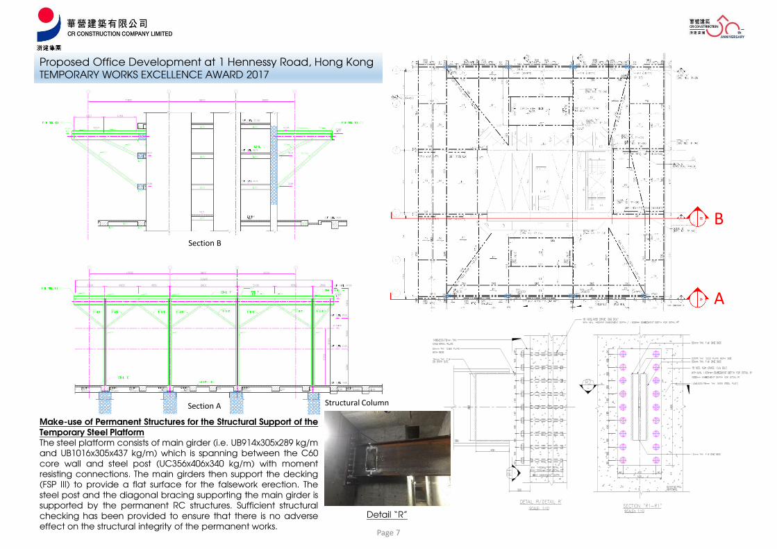
Upon the completion of concreting works at7/F, SB1 is connected to the core wall throughthe designed baseplate according to Detail“R”. Lastly, all the diagonal bracing (SB7, SB9and SB11) is installed correspondingly.
The temporary falsework and the temporarybracing for SP1 are not removed until all thesteel members has been fully installed and therelevant core wall has obtained its designstrength (C60). Falsework (Ring-lock system)
Temporary Steel Platform for Main beam erection
Page 7
Section B
Section A
B
A
Proposed Office Development at 1 Hennessy Road, Hong KongTEMPORARY WORKS EXCELLENCE AWARD 2017
Make-use of Permanent Structures for the Structural Support of theTemporary Steel PlatformThe steel platform consists of main girder (i.e. UB914x305x289 kg/mand UB1016x305x437 kg/m) which is spanning between the C60core wall and steel post (UC356x406x340 kg/m) with momentresisting connections. The main girders then support the decking(FSP III) to provide a flat surface for the falsework erection. Thesteel post and the diagonal bracing supporting the main girder issupported by the permanent RC structures. Sufficient structuralchecking has been provided to ensure that there is no adverseeffect on the structural integrity of the permanent works.
Structural Column
Detail “R”

Page 8
Dismantling of Temporary Steel Deck
The sequence for the dismantling of the temporary consist of 5 stages. Ingeneral, the general dismantling sequence will start with FSPIII sheet piledecking -> Secondary beam -> Diagonal steel member -> Main beam ->Vertical Post -> steel plate and anchor bolts.Stage 1: 8 nos. of T25 stainless steel omega lifting hook to be preinstalled on
the inclined column (anchored on the permanent structures);Stage 2: After the steel member has been fastened and secured on the lifting
hook, utilization of winch and chain block to help safely descent thedetached steel member to flat roof at 3F;
Stage 3: Once the steel member reached at 3F, it would be hauled to thelifting area by another winch system setup at 3F;
Stage 4: The detached steel member will be lifted to delivery trucks fortransport to steel fabrication yard.
Proposed Office Development at 1 Hennessy Road, Hong KongTEMPORARY WORKS EXCELLENCE AWARD 2017
Graphical demonstration for diagonal steel member dismantling
Typical details for T25 Stainless steel omega lifting hook

Page 9
Proposed Office Development at 1 Hennessy Road, Hong KongTEMPORARY WORKS EXCELLENCE AWARD 2017
Safety Management:The safety management function for the temporarysteel deck are fully complied with the safetymanagement functions of the RC stated in TechnicalMemorandum for Supervision Plans 2009.
Risk assessment is prepared before works & design briefto worker is carried out to remind the critical issue.Particular protection to vertical steel post is providedduring steel beam erection to avoid crash by liftingplatform. Besides, fully “Fall Assets System” is providedfor workers who is working at height. Designatedperson to monitor the welding works with coveringsleet.
Daily basic briefing / training for all related workers areconducted before works commencement.
Quality Supervision:The working procedures for the temporary steel deck isprepared strictly in accordance with the guidelinesstated in Code of Practice for Site Supervision 2009.The temporary steel deck is defined as case 2temporary works.
Designated site foreman monitors the whole process.Daily brief of all works is carried out beforecommencement. Checklist is signed by subcontractor,T1, T4 & representative of RSE after works. Setting out ofcast-in bolt is checked before casting. An HKOLAS labis employed to test all welding works following therequirement of Code of Practice.
Environmental Issue:This scaffolding mostly uses reusable metal to replacetraditional single-used bamboo. Moreover, rising of thescaffold level reduces the use of bamboo substantiallyfor about 6-storey-quantity of material. Therefore, thismethodology is eco-friendly which could reducenumerous waste of resource.
Particular Daily Checklist for steel deck construction and
Signed by T1, T4 & representative of RSE
Mobile lifting – platform for working at height
Protective Handrail along steel deck
Provided Proper Safety access between 3/F floor
level and steel deck
Briefing / Training for worker before
steel deck construction
Pull out testing by certified laboratory
Storage area under steel deck
Construction falsework on steel deck

Proposed Office Development at 1 Hennessy Road, Hong KongTEMPORARY WORKS EXCELLENCE AWARD 2017
Page 10
Contribution to safe and successful completion of the project
1. The Steel Deck provides the working space for material storageunderneath.
2. Minimizing the number of scaffold (3/F to 7/F) means the max. heightof scaffold is reduced from (18.9mPD to 52.9mPD) to (33.125mPD to52.9mPD), the chance of “working at height” is therefore reduced.
3. The impact on site logistic is reduced due to limited space of siteentrance and unloading area.
4. The required member of workers is reduced, which reduces the sitesafety risk.
Top View
View from Junction of Lockhart Road & Hennessy Road
View from Junction of Arsenal Street & Hennessy Road
View from HKT Lockhart Road Exchange BuildingFalsework erecting on steel desk Under steel desk


![Safety Management & Site Establishment · e.g. as falsework supporting a formwork system (to be discussed ... Tower scaffolding ... BS 5975[12] defines falsework as](https://img.dokumen.tips/doc/110x75/5b0a3b487f8b9ae61b8bc6a4/safety-management-site-as-falsework-supporting-a-formwork-system-to-be-discussed.jpg)