Embed Size (px)
Citation preview
Software
APAX-5071
Software Manual

CopyrightThe documentation and the software included with this product are copyrighted 2012by Advantech Co., Ltd. All rights are reserved. Advantech Co., Ltd. reserves the rightto make improvements in the products described in this manual at any time withoutnotice. No part of this manual may be reproduced, copied, translated or transmittedin any form or by any means without the prior written permission of Advantech Co.,Ltd. Information provided in this manual is intended to be accurate and reliable. How-ever, Advantech Co., Ltd. assumes no responsibility for its use, nor for any infringe-ments of the rights of third parties, which may result from its use.
AcknowledgementsIntel and Pentium are trademarks of Intel Corporation.
Microsoft Windows and MS-DOS are registered trademarks of Microsoft Corp.
All other product names or trademarks are properties of their respective owners.
Notes on the ManualThis is the Software Manual for the Advantech APAX-5570 product. This manual willhelp guide the end user through implementation and use of the software portion ofthis product.
What is covered in this manual:
This manual will give a general overview of the Windows XP Embedded operatingsystem, most of the applications that are included with Windows XP Embedded aswell as the applications added and/or created by Advantech Corporation in the Win-dows XP Embedded image. This manual will also cover installation and use of devel-opment and utility software that is needed. It will also reference optional software thatcan be used by the end user with the Windows XP Embedded Operating system.
What is not covered in this manual:
This manual will reference the hardware but does not contain hardware setup infor-mation, wiring information, electrical specifications or any detailed hardware informa-tion. Please refer to the hardware manual for this information.
Edition 1
July 2012
APAX-5071 Software Manual ii
Contents
Chapter 1 Quick Start ...........................................11.1 Hardware System Diagram ....................................................................... 21.2 Installing the ADAM/APAX .NET utility...................................................... 21.3 Configuring APAX-5071 with ADAM/APAX .NET ..................................... 31.4 Configure & Access Data in PROFINET Master ....................................... 5
Chapter 2 Analog I/O Board Settings ................112.1 Analog I/O Board Settings....................................................................... 12
Appendix A ADAM/APAX .NET Utility Operation.15A.1 ADAM/APAX .NET Utility General Window............................................. 16
A.1.1 Menu........................................................................................... 17A.1.2 Toolbar........................................................................................ 18A.1.3 Module Tree Display Area .......................................................... 18A.1.4 Status Display Area .................................................................... 19
A.2 General Configuration ............................................................................. 19A.2.1 Information .................................................................................. 20A.2.2 Setting......................................................................................... 20
A.3 I/O Module Configuration ........................................................................ 21A.3.1 Analog Input Modules ................................................................. 22A.3.2 Analog Output Module ................................................................ 26A.3.3 Digital Input Module .................................................................... 29A.3.4 Digital Output Module ................................................................. 30A.3.5 Counter Module .......................................................................... 31
Appendix B PROFINET Address Mapping Table.37B.1 PROFINET Address Mapping Table (0x)................................................ 38
iii APAX-5071 Software Manual

APAX-5071 Software Manual iv

Chapter 1
1 Quick Start
1.1 Hardware System Diagram APAX-5071 coupler with APAX-5000 I/O modules will be controlled by a PROFINETmaster. Here, we use Siemens S7-300 PLC as example. The complete systemincludes APAX series, S7-300 PLC and a PC used to configure the setting of S7-300PLC. The system hardware architecture can be shown as figure below.
1.2 Installing the ADAM/APAX .NET utilityAdvantech provides the ADAM/APAX .NET utility which allows developers and endusers to see APAX-5071 and connected I/O modules, perform configurations, andsimple testing of the I/O. This software can be helpful when checking wiring inputsprior to installing the runtime project. It is also able to detect and test other Advantechsupported hardware for this product such as Ethernet or Serial I/O. (ADAM-4000,ADAM-5000 and ADAM-6000 series). Therefore, you need to install ADAM/APAX.NET utility first to configure APAX-5071 and related APAX-5000 I/O modules. Afterthat, you can use other software package which supports PROFINET protocol (suchas Siemens S7-300 series) to perform write or read action to APAX-5071.
The installation file is contained in the CD. When you launch the CD, select the APAXSoftware button and click the ADAM/APAX .NET Utility button to find the installationfile. Besides, you always can link to the web site http://www.advantech.com and clickinto the Download area under the Support site to get the latest version of the ADAM/APAX .NET utility.
Note! 1. Do not use hub between the PROFINET master and APAX-5071. Only Ethernet switch is acceptable.
2. The quality of the network will influence the PROFINET communica-tion performance, so make the network as simple as possible.
APAX-5071 Software Manual 2

Chapter 1
Quick S
tart
1.3 Configuring APAX-5071 with ADAM/APAX .NETLaunch ADAM/APAX .NET utility by selecting Start >> All Programs >> AdvantechAutomation >> AdamApax .NET Utility >> AdamApax .NET Utility. On the leftside of the utility window, you can see several items showing IP address under theEthernet item. (These items represent the Ethernet port on your computer). Click onthe item showing the IP address which stands for the specific port used to connectwith APAX-5071 module, and then click the icon Search Modules on the toolbar. (Oryou can right click the item and select Search option.) Then you should be able tosee APAX-5071 item showing under the IP address item, as shown below.
Click the item showing the APAX-5071 (with APAX-5071 IP address). Type the cor-rect password on the pop-up window. All the connected APAX-5000 I/O modules willshow under the APAX-5071 item. (In this example, they are APAX-5017, APAX-5028and APAX-5040 and APAX-5046)
Note! Before you start search the APAX-5071 module in utility, remember to change that APAX-5071 module's mode to Utility mode. Refer to APAX-5071 Hardware Manual for how to configure APAX-5071 mode.
3 APAX-5071 Software Manual
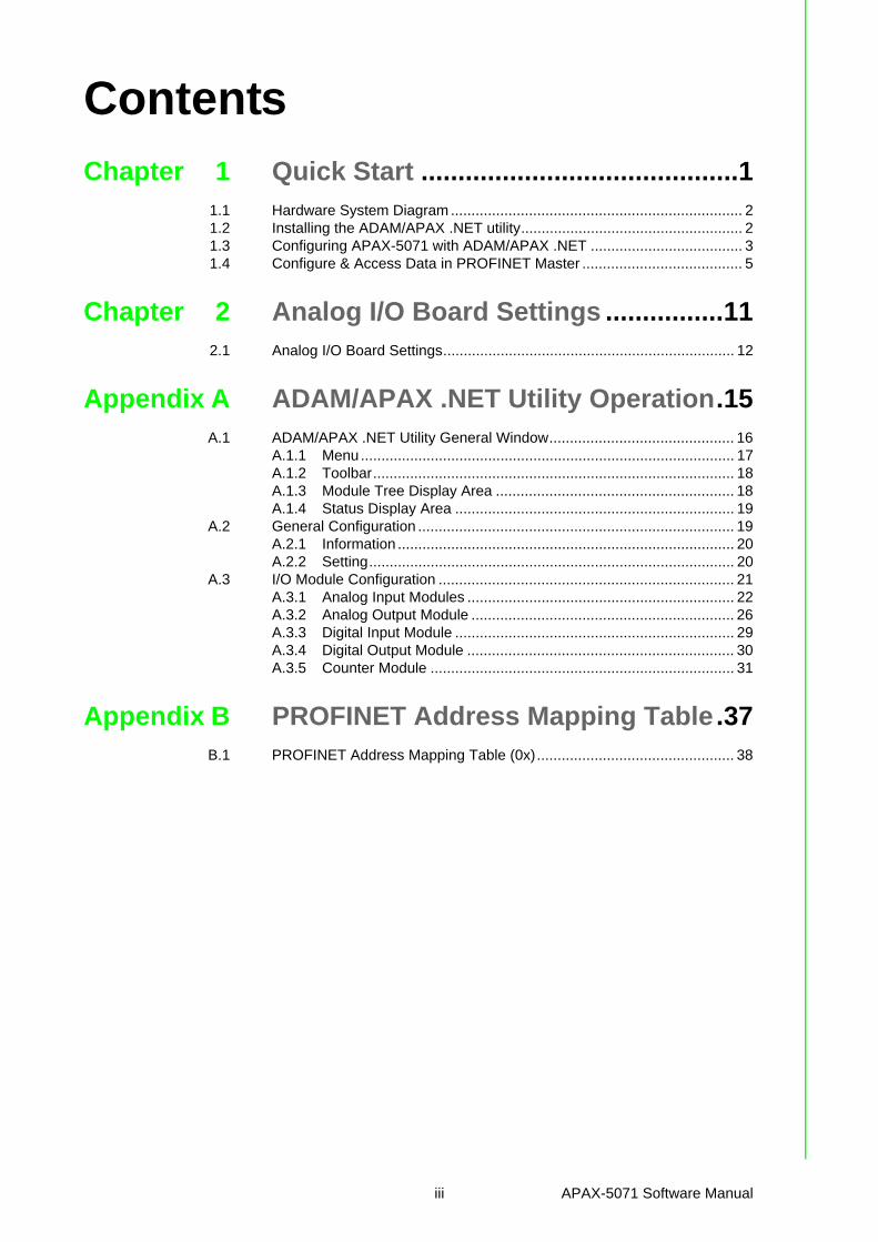
On the right window, you can perform all related configurations toward APAX-5071through the two tabs: Information and Setting. Refer to the figure below. You canupgrade related firmware to selected APAX-5071 coupler on the Information tab.Click the I/O modules items under the APAX-5071 item, then you can configure orread/write specific I/O modules.
APAX-5071 Software Manual 4

Chapter 1
Quick S
tart
1.4 Configure & Access Data in PROFINET MasterHere, we use a Siemens S7-300 CPU 315-2 PN/DP PLC to connect with APAX-5071and related APAX-5000 I/O modules. So we need to use Siemens STEP 7 softwareto configure the connection between S7-300 PLC and APAX-5071. First, launch Sie-mens STEP 7 software, create a new project as figure below..
Right Click the project item and select Insert New Object >> SIMATIC 300 Series tocreate the object representing the Siemens S7-300 PLC.
5 APAX-5071 Software Manual
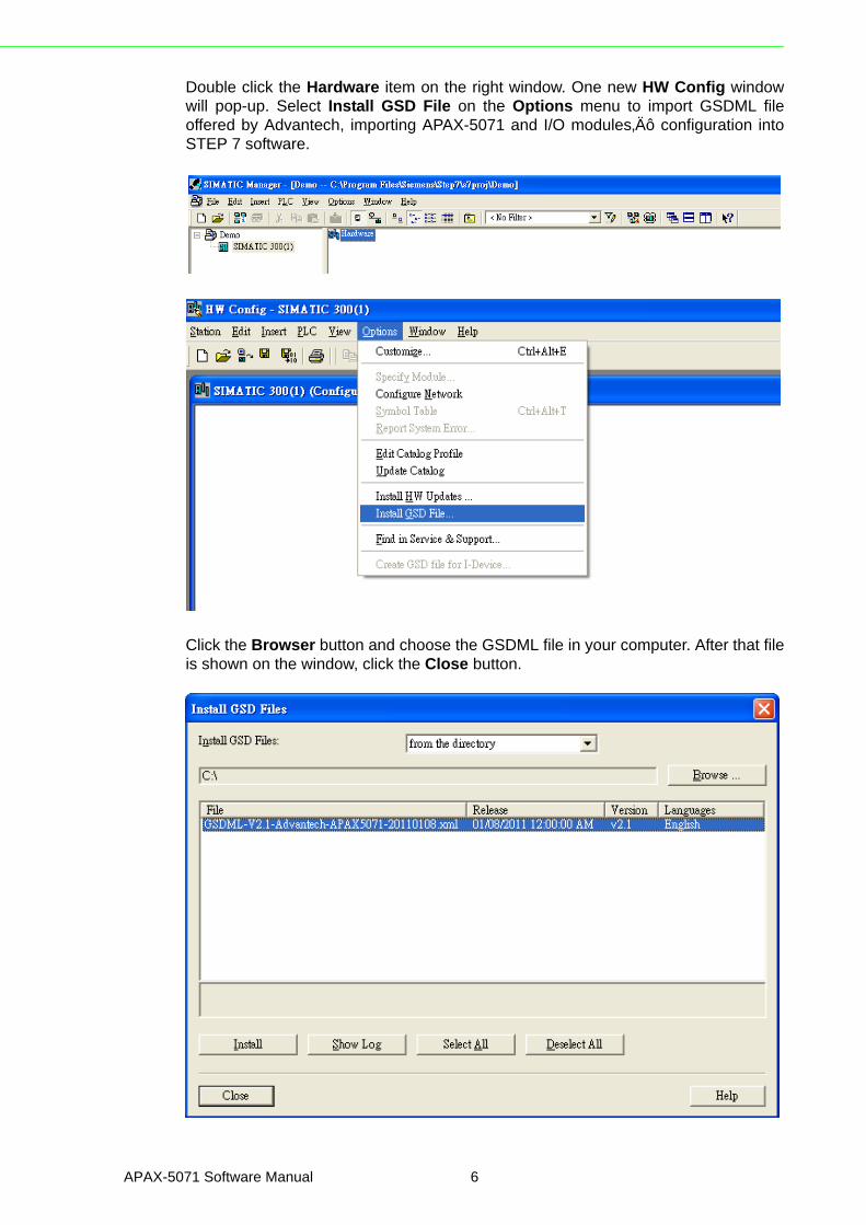
Double click the Hardware item on the right window. One new HW Config windowwill pop-up. Select Install GSD File on the Options menu to import GSDML fileoffered by Advantech, importing APAX-5071 and I/O modules’ configuration intoSTEP 7 software.
Click the Browser button and choose the GSDML file in your computer. After that fileis shown on the window, click the Close button.
APAX-5071 Software Manual 6

Chapter 1
Quick S
tart
You can see APAX-5071 and APAX-5000 I/O modules showing on the right side win-dow now, as shown by figure below.
You can drag the component you want to the left window for programming usage.First, a PROFINET bus needs to be established. Then, APAX-5071 componentneeds to be dragged to attach on the PROFINET bus on the upper left window. Afterthat, APAX-5000 I/O components can be dragged to selected “slot” raw on thelower left window.
7 APAX-5071 Software Manual

When you complete your program, you need to configure networking setting forAPAX-5071. Select Ethernet >> Edit Ethernet Node on the PLC menu.
An Edit Ethernet Node window will pop-up. Ethernet node means APAX-5071 cou-pler module. You can type the correct MAC address into the MAC address text box orselect it by clicking the Browser button. You also need to type the correct IP addressof APAX-5071 on the IP address text box in the Set IP configuration area. After theconfiguration is done, click the Close button.
APAX-5071 Software Manual 8

Chapter 1
Quick S
tart
After the configuration is done, you can download your program to the Siemens S7-300 PLC by selecting Download item on the PLC menu. If all configurations are cor-rect, you should be able to see the NETWORK LED on APAX-5071 flash with greencolor, and it means the AR connection is built.
9 APAX-5071 Software Manual

APAX-5071 Software Manual 10

Chapter 2
2 Analog I/O Board Settings
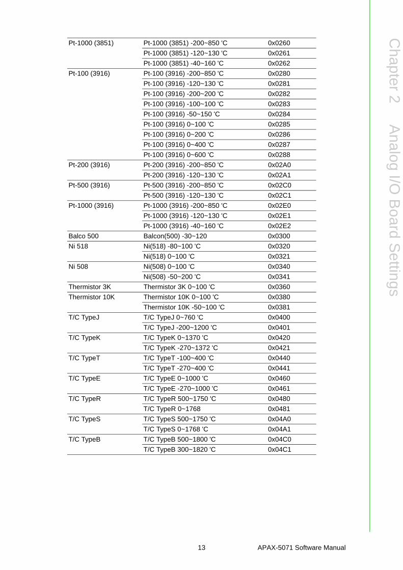
2.1 Analog I/O Board SettingsRange Settings for Analog I/O Boards. These ranges are provided for reference. Notall boards support all ranges. Please see hardware manual for valid ranges for a par-ticular board.
Setting Type Value (Hex)
Millivolts DC(mV)
+/- 15mV 0x0100
+/- 50mV 0x0101
+/- 100mV 0x0102
+/- 150mV 0x0103
+/- 500mV 0x0104
0~150mV 0x0105
0~500mV 0x0106
Volts DC (V)
+/- 1V 0x0140
+/- 2.5V 0x0141
+/- 5V 0x0142
+/- 10V 0x0143
+/- 15V 0x0144
0~1V 0x0145
0~2.5V 0x0146
0~5V 0x0147
0~10V 0x0148
0~15V 0x0149
Milliamps (mA) 4~20mA 0x0180
+/-20mA 0x0181
0~20mA 0x0182
Counter settings Pulse/DIR 0x01C0
Up/Down 0x01C1
Up 0x01C2
Frequency 0x01C3
AB 1X 0x01C4
AB 2X 0x01C5
AB 4X 0x01C6
Pt-100 (3851) Pt-100 (3851) -200~850 'C 0x0200
Pt-100 (3851) -120~130 'C 0x0201
Pt-100 (3851) -200~200 'C 0x0202
Pt-100 (3851) -100~100 'C 0x0203
Pt-100 (3851) -50~150 'C 0x0204
Pt-100 (3851) 0~100 'C 0x0205
Pt-100 (3851) 0~200 'C 0x0206
Pt-100 (3851) 0~400 'C 0x0207
Pt-100 (3851) 0~600 'C 0x0208
Pt-200 (3851) Pt-200 (3851) -200~850 'C 0x0220
Pt-200 (3851) -120~130 'C 0x0221
Pt-500 (3851) Pt-500 (3851) -200~850 'C 0x0240
Pt-500 (3851) -120~130 'C 0x0241
APAX-5071 Software Manual 12
Chapter 2
Analog
I/OB
oardS
ettings
Pt-1000 (3851) Pt-1000 (3851) -200~850 'C 0x0260
Pt-1000 (3851) -120~130 'C 0x0261
Pt-1000 (3851) -40~160 'C 0x0262
Pt-100 (3916) Pt-100 (3916) -200~850 'C 0x0280
Pt-100 (3916) -120~130 'C 0x0281
Pt-100 (3916) -200~200 'C 0x0282
Pt-100 (3916) -100~100 'C 0x0283
Pt-100 (3916) -50~150 'C 0x0284
Pt-100 (3916) 0~100 'C 0x0285
Pt-100 (3916) 0~200 'C 0x0286
Pt-100 (3916) 0~400 'C 0x0287
Pt-100 (3916) 0~600 'C 0x0288
Pt-200 (3916) Pt-200 (3916) -200~850 'C 0x02A0
Pt-200 (3916) -120~130 'C 0x02A1
Pt-500 (3916) Pt-500 (3916) -200~850 'C 0x02C0
Pt-500 (3916) -120~130 'C 0x02C1
Pt-1000 (3916) Pt-1000 (3916) -200~850 'C 0x02E0
Pt-1000 (3916) -120~130 'C 0x02E1
Pt-1000 (3916) -40~160 'C 0x02E2
Balco 500 Balcon(500) -30~120 0x0300
Ni 518 Ni(518) -80~100 'C 0x0320
Ni(518) 0~100 'C 0x0321
Ni 508 Ni(508) 0~100 'C 0x0340
Ni(508) -50~200 'C 0x0341
Thermistor 3K Thermistor 3K 0~100 'C 0x0360
Thermistor 10K Thermistor 10K 0~100 'C 0x0380
Thermistor 10K -50~100 'C 0x0381
T/C TypeJ T/C TypeJ 0~760 'C 0x0400
T/C TypeJ -200~1200 'C 0x0401
T/C TypeK T/C TypeK 0~1370 'C 0x0420
T/C TypeK -270~1372 'C 0x0421
T/C TypeT T/C TypeT -100~400 'C 0x0440
T/C TypeT -270~400 'C 0x0441
T/C TypeE T/C TypeE 0~1000 'C 0x0460
T/C TypeE -270~1000 'C 0x0461
T/C TypeR T/C TypeR 500~1750 'C 0x0480
T/C TypeR 0~1768 0x0481
T/C TypeS T/C TypeS 500~1750 'C 0x04A0
T/C TypeS 0~1768 'C 0x04A1
T/C TypeB T/C TypeB 500~1800 'C 0x04C0
T/C TypeB 300~1820 'C 0x04C1
13 APAX-5071 Software Manual

APAX-5071 Software Manual 14

Appendix A
A ADAM/APAX .NET Utility Operation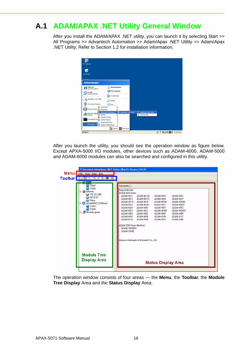
A.1 ADAM/APAX .NET Utility General WindowAfter you install the ADAM/APAX .NET utility, you can launch it by selecting Start >>All Programs >> Advantech Automation >> Adam/Apax .NET Utility >> Adam/Apax.NET Utility. Refer to Section 1.2 for installation information.
After you launch the utility, you should see the operation window as figure below.Except APXA-5000 I/O modules, other devices such as ADAM-4000, ADAM-5000and ADAM-6000 modules can also be searched and configured in this utility.
The operation window consists of four areas --- the Menu, the Toolbar, the ModuleTree Display Area and the Status Display Area.
APAX-5071 Software Manual 16
Appendix A
AD
AM
/AP
AX
.NE
TU
tilityO
peration
A.1.1 MenuThe menu at the top of the operation window contains:
The File menu 1. Open Favorite Group - You can configure your favorite group and save the
configuration into one file. Using this option, you can load your configuration file for favorite group.
2. Save Favorite Group - You can configure your favorite group and save the con-figuration into one file. Using this option, you can save your favorite group into one configuration file.
3. Auto-Initial Group - If you want to have the same favorite group configuration when you exit ADAM/APAX .NET utility and launch it again, you need to check this option.
4. Exit - Exit ADAM/APAX .NET Utility.
The Tools menu1. Search - Search if there are any remote I/O modules connected. For I/O mod-
ules communicated by serial (such as ADAM-4000 modules), click the COM1 item (COM 2 is an internal COM port) under Serial item in the Module Tree Dis-play Area first before you click this button. For I/O modules communicated by Ethernet (such as APAX-5071 with APAX-5000 I/O modules, ADAM-6000 mod-ules), click the Ethernet item in the Module Tree Display Area first before you click this button.
2. Add Devices to Group - You can add any I/O modules to your favorite group by this option. You need to select the device you want to add in the Module Tree Display Area (it will be described below) first, and then select this option to add.
3. Terminal for Command Testing - ADAM modules support ASCII commands and Modbus as communication protocol. You can launch the terminal to com-municate with remote module by these two kinds of protocols directly. Refer to ADAM-4000, ADAM-5000 and ADAM-6000 manual for ASCII and Modbus com-mand.
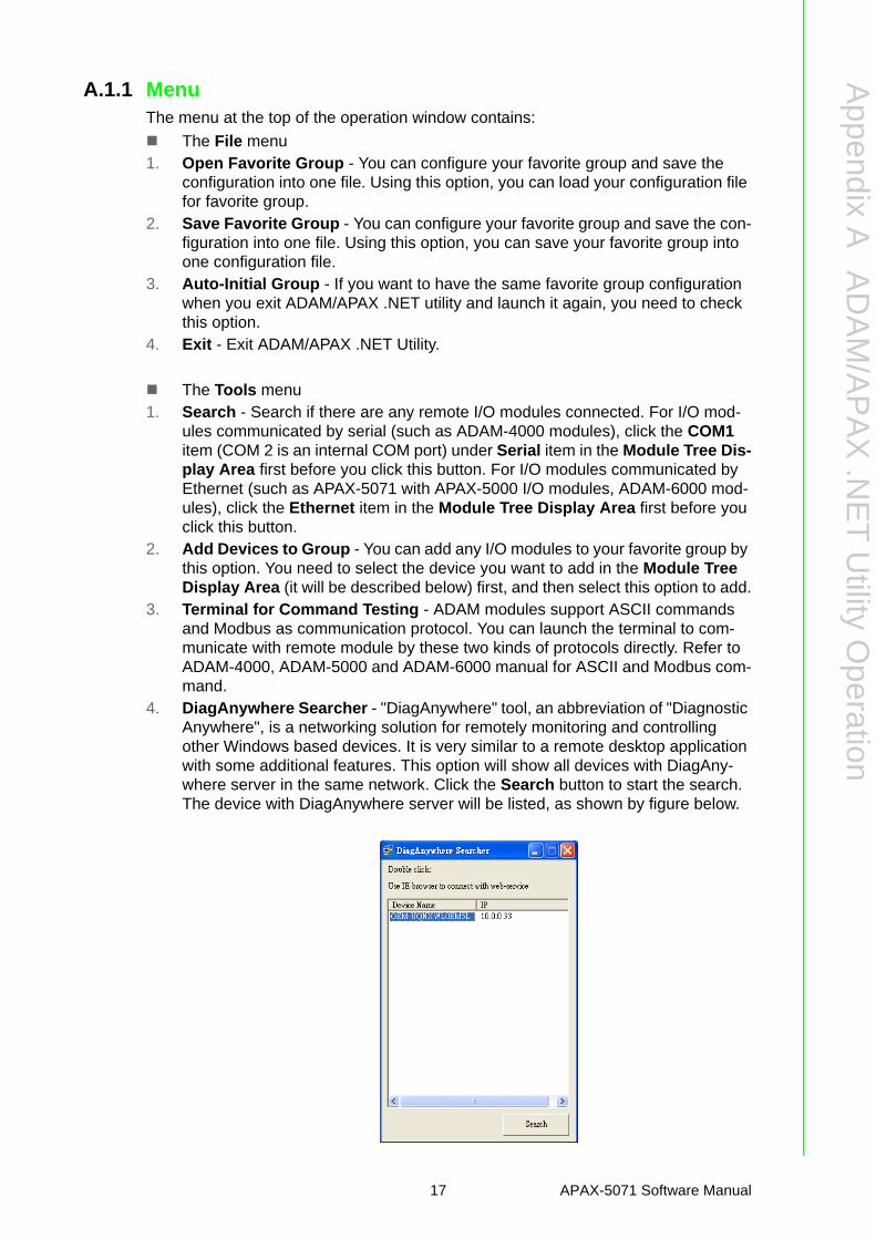
4. DiagAnywhere Searcher - "DiagAnywhere" tool, an abbreviation of "Diagnostic Anywhere", is a networking solution for remotely monitoring and controlling other Windows based devices. It is very similar to a remote desktop application with some additional features. This option will show all devices with DiagAny-where server in the same network. Click the Search button to start the search. The device with DiagAnywhere server will be listed, as shown by figure below.
17 APAX-5071 Software Manual

5. Print Screen - You can acquire current utility window image and save it as an image file (*.bmp).
6. Monitor Stream/Adam5000 Event Data - This functionality is for ADAM/APAX module which supports Data Stream/Event function. If you enable Data Stream functions and configure this computer (where the utility is installed) as the host to receive data, then you can use this option to receive and view the data.
7. Monitor Peer-to-Peer (Event Trigger) - ADAM-6000 modules support Peer-to-Peer function. You can use this option to see data transferred from connected ADAM-6000 module which is enabled Peer-to-Peer function. Refer to ADAM-6000 manual for more detail.
8. Monitor GCL IO Data Message - ADAM-6000 modules support GCL function. You can use this option to see data transferred from connected ADAM-6000 module which is enabled GCL function. Refer to ADAM-6000 manual for more detail.
The Setup menu1. Favorite Group - You can configure your favorite group including add one new
device (only for remote device), modify or delete one current device, sort current devices and diagnose connection to one device.
2. Refresh COM and LAN node - ADAM/APAX .NET utility will refresh the serial and LAN network connection situation.
3. Add COM Port Tree Nodes - This option is used to add serial COM ports in APAX/ADAM.NET Utility.
4. ShowTreeView - Check this option to display the Module Tree Display Area.5. Enable Calibration Function - Check this option to let APAX-5000 analog
module able to perform calibration procedure.
The Help menu 1. Check Up-to-Date on the Web - Choose this option, it will automatically con-
nect to Advantech download website. You can download the latest utility there.2. About ADAM/APAX .NET Utility - Choose this option, you can see version of
ADAM/APAX .NET Utility installed on your computer.
A.1.2 ToolbarThe eight buttons on toolbar represent the eight common used items from the Menu.Refer to figure below for the definition of each button:
A.1.3 Module Tree Display AreaADAM/APAX .NET Utility is one complete software tool that all APAX and ADAM I/Omodule can be configure and operated in this utility. The Module Tree Display Areais on the left part of the utility operation window. There are four categories in theModule Tree Display Area:
APAX-5071 Software Manual 18

Appendix A
AD
AM
/AP
AX
.NE
TU
tilityO
peration
SerialAll serial remote I/O Modules connected to the host computer will be listed in this cat-egory. You also can configure COM port parameter (such as baud rate, parity, stopbit) here.
EthernetAll Ethernet remote I/O modules (including APAX-5071 modules) connected to thehost computer will be listed in this category.
ADAM-4500/5510 SeriesAll ADAM-4500 and ADAM-5000 controllers connected to the host computer throughserial interface in the same system, such as ADAM-5510 or ADAM-4501, will belisted in this category. Simply click this item all related modules will be displayedautomatically.
Favorite GroupYou can define which devices listed in Serial or Ethernet categories above into yourpersonal favorite group. This will make you easier to find your interested modules.Click on the ADAM device item under Favorite group item, and select Favorite >>New in Setup menu to create a new group. After you create your own group, click onyour group and select Favorite >> New in Setup menu to add any remote devicesinto your group. You can also select Diagnose connection to check the communica-tion.
A.1.4 Status Display AreaStatus Display Area, on the right part of utility operation window, is the main screenfor operation. When you select different items in Modules Tree Display Area, StatusDisplay Area will change dependently. You can do all configurations and tests on thisarea.
A.2 General ConfigurationIf you click the APAX-5071 item in the Module Tree Display Area, the Status Dis-play Area should looks as figure below. There will be three configuration tabs shownon the Status Display Area: Information, Setting, and EDS file export.
19 APAX-5071 Software Manual

A.2.1 Information
Refer to figure above. You can download related firmware to selected APAX-5071 byclicking the Download button in the Firmware and Kernel area. You also can namethe selected APAX-5071 module by the Name and Description text box in the Devicearea. All I/O modules connected with APAX-5071 module with its ID number arelisted in the Description tab (the left tab). You can see all I/O modules supported byAPAX-5071 by the Support Modules tab.
A.2.2 SettingHere, you can change related networking setting, including IP address, Subnet Mask,Default Gateway, and Host Idle Timeout. After you have complete the setting, clickthe Apply button to apply the setting. Remember these parameters will be usedwhen you configure the network setting on the PROFINET master.
APAX-5071 Software Manual 20
Appendix A
AD
AM
/AP
AX
.NE
TU
tilityO
peration
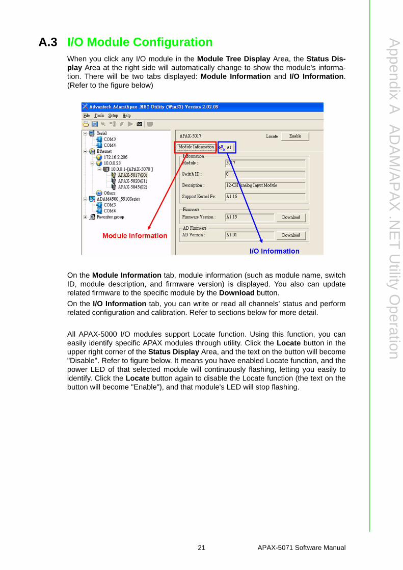
A.3 I/O Module ConfigurationWhen you click any I/O module in the Module Tree Display Area, the Status Dis-play Area at the right side will automatically change to show the module's informa-tion. There will be two tabs displayed: Module Information and I/O Information.(Refer to the figure below)
On the Module Information tab, module information (such as module name, switchID, module description, and firmware version) is displayed. You also can updaterelated firmware to the specific module by the Download button.
On the I/O Information tab, you can write or read all channels' status and performrelated configuration and calibration. Refer to sections below for more detail.
All APAX-5000 I/O modules support Locate function. Using this function, you caneasily identify specific APAX modules through utility. Click the Locate button in theupper right corner of the Status Display Area, and the text on the button will become"Disable". Refer to figure below. It means you have enabled Locate function, and thepower LED of that selected module will continuously flashing, letting you easily toidentify. Click the Locate button again to disable the Locate function (the text on thebutton will become "Enable"), and that module's LED will stop flashing.
21 APAX-5071 Software Manual
A.3.1 Analog Input Modules
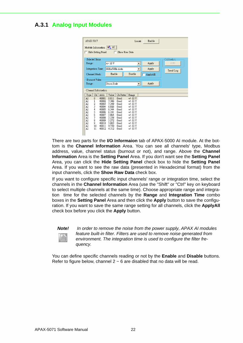
There are two parts for the I/O Informaion tab of APAX-5000 AI module. At the bot-tom is the Channel Information Area. You can see all channels' type, Modbusaddress, value, channel status (burnout or not), and range. Above the ChannelInformation Area is the Setting Panel Area. If you don't want see the Setting PanelArea, you can click the Hide Setting Panel check box to hide the Setting PanelArea. If you want to see the raw data (presented in Hexadecimal format) from theinput channels, click the Show Raw Data check box.
If you want to configure specific input channels' range or integration time, select thechannels in the Channel Information Area (use the "Shift" or "Ctrl" key on keyboardto select multiple channels at the same time). Choose appropriate range and integra-tion time for the selected channels by the Range and Integration Time comboboxes in the Setting Panel Area and then click the Apply button to save the configu-ration. If you want to save the same range setting for all channels, click the ApplyAllcheck box before you click the Apply button.
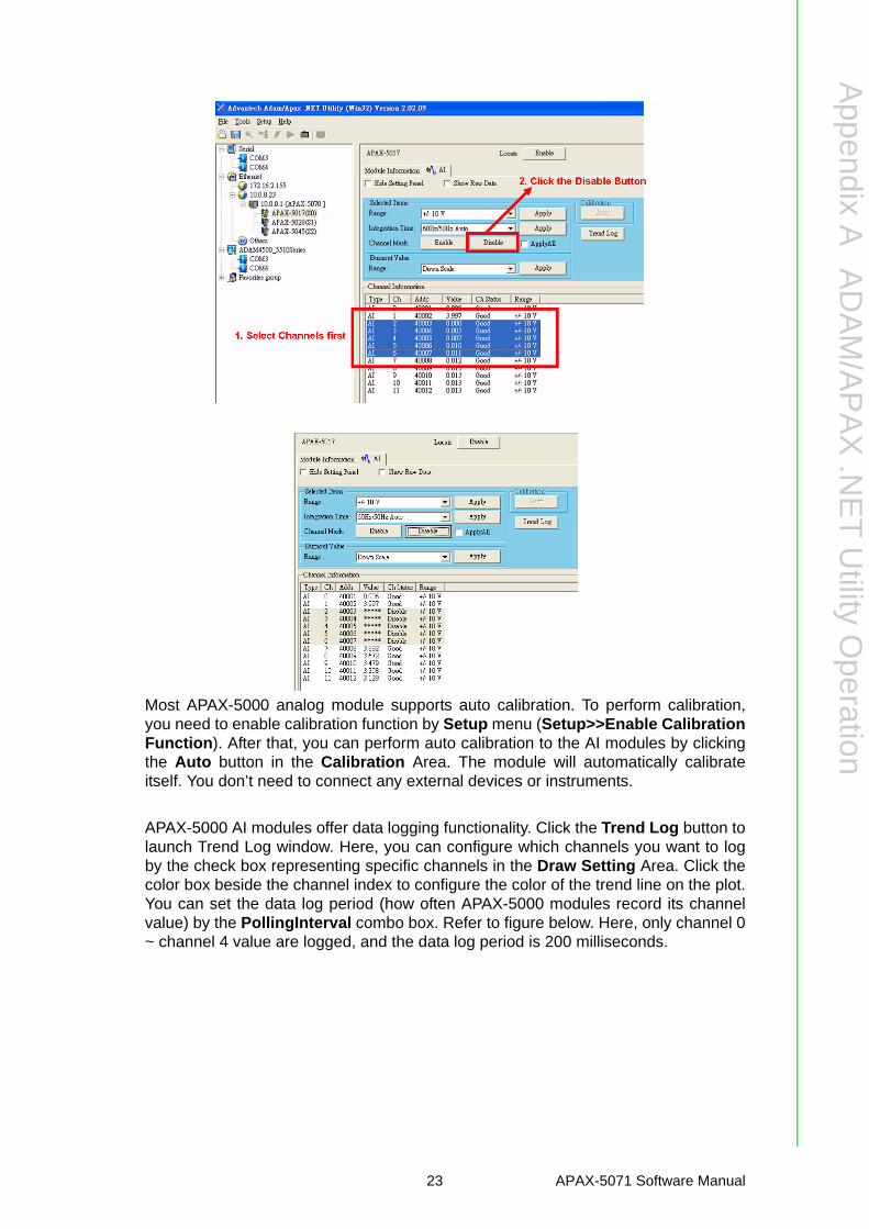
You can define specific channels reading or not by the Enable and Disable buttons.Refer to figure below, channel 2 ~ 6 are disabled that no data will be read.
Note! In order to remove the noise from the power supply, APAX AI modules feature built-in filter. Filters are used to remove noise generated from environment. The integration time is used to configure the filter fre-quency.
APAX-5071 Software Manual 22
Appendix A
AD
AM
/AP
AX
.NE
TU
tilityO
peration
Most APAX-5000 analog module supports auto calibration. To perform calibration,you need to enable calibration function by Setup menu (Setup>>Enable CalibrationFunction). After that, you can perform auto calibration to the AI modules by clickingthe Auto button in the Calibration Area. The module will automatically calibrateitself. You don’t need to connect any external devices or instruments.
APAX-5000 AI modules offer data logging functionality. Click the Trend Log button tolaunch Trend Log window. Here, you can configure which channels you want to logby the check box representing specific channels in the Draw Setting Area. Click thecolor box beside the channel index to configure the color of the trend line on the plot.You can set the data log period (how often APAX-5000 modules record its channelvalue) by the PollingInterval combo box. Refer to figure below. Here, only channel 0~ channel 4 value are logged, and the data log period is 200 milliseconds.
23 APAX-5071 Software Manual
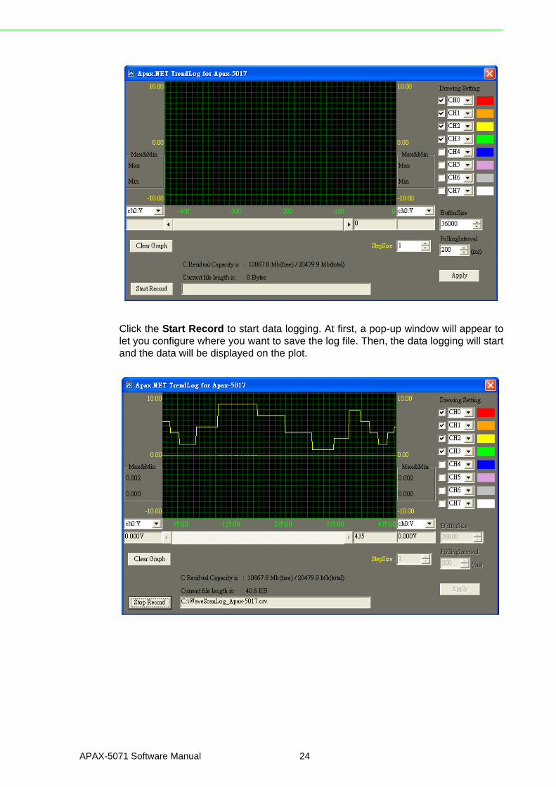
Click the Start Record to start data logging. At first, a pop-up window will appear tolet you configure where you want to save the log file. Then, the data logging will startand the data will be displayed on the plot.
APAX-5071 Software Manual 24
Appendix A
AD
AM
/AP
AX
.NE
TU
tilityO
peration
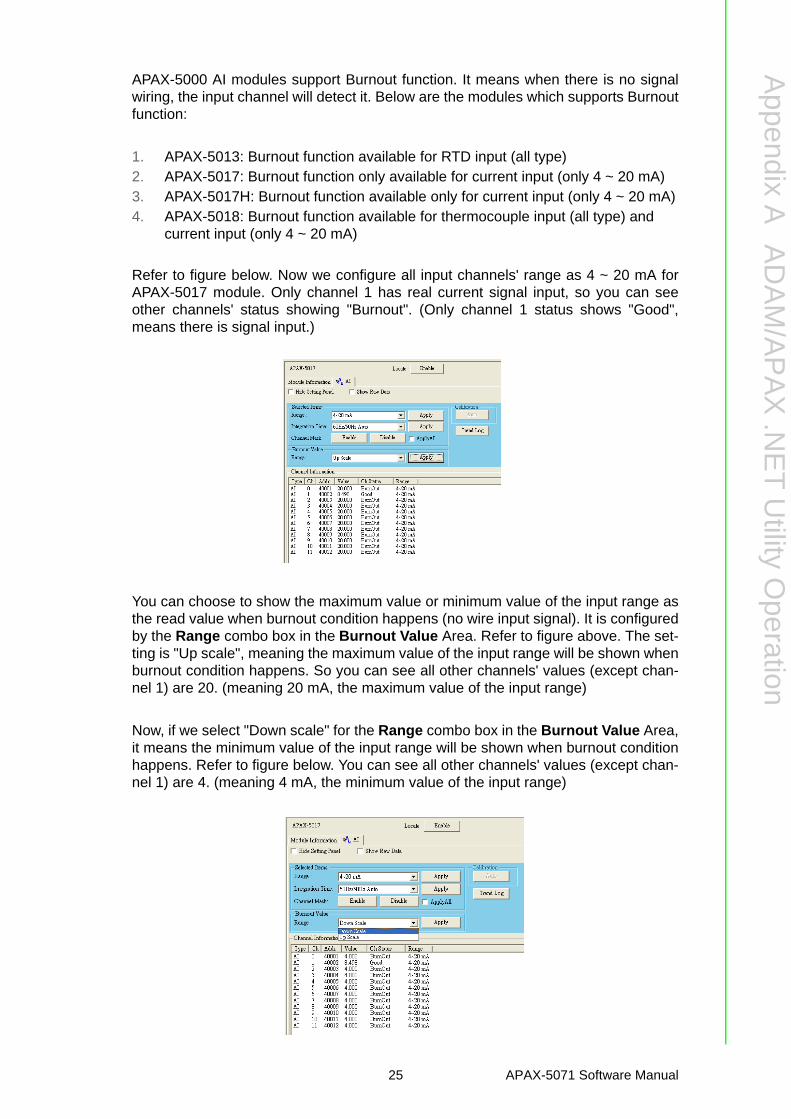
APAX-5000 AI modules support Burnout function. It means when there is no signalwiring, the input channel will detect it. Below are the modules which supports Burnoutfunction:
1. APAX-5013: Burnout function available for RTD input (all type)2. APAX-5017: Burnout function only available for current input (only 4 ~ 20 mA)3. APAX-5017H: Burnout function available only for current input (only 4 ~ 20 mA)4. APAX-5018: Burnout function available for thermocouple input (all type) and
current input (only 4 ~ 20 mA)
Refer to figure below. Now we configure all input channels' range as 4 ~ 20 mA forAPAX-5017 module. Only channel 1 has real current signal input, so you can seeother channels' status showing "Burnout". (Only channel 1 status shows "Good",means there is signal input.)
You can choose to show the maximum value or minimum value of the input range asthe read value when burnout condition happens (no wire input signal). It is configuredby the Range combo box in the Burnout Value Area. Refer to figure above. The set-ting is "Up scale", meaning the maximum value of the input range will be shown whenburnout condition happens. So you can see all other channels' values (except chan-nel 1) are 20. (meaning 20 mA, the maximum value of the input range)
Now, if we select "Down scale" for the Range combo box in the Burnout Value Area,it means the minimum value of the input range will be shown when burnout conditionhappens. Refer to figure below. You can see all other channels' values (except chan-nel 1) are 4. (meaning 4 mA, the minimum value of the input range)
25 APAX-5071 Software Manual

A.3.2 Analog Output Module
There are two parts for the I/O Information tab of APAX-5000 AO module. At the bot-tom is the Channel Information Area. You can see all channels' type, Modbusaddress, value, range, startup value (the initial value when the AO module is power-on) and safety value (the default value when the communication is broken). Abovethe Channel Information Area is the Setting Panel Area. If you don't want see theSetting Panel Area, you can click the Hide Setting Panel check box to hide the Set-ting Panel Area. If you want to see the raw data (presented in Hexadecimal format)from the output channels, click the Show Raw Data check box.
If you want to configure specific output channels' range, select the channels in theChannel Information Area. Choose appropriate range by the Range combo box inthe Setting Panel Area and then click the Apply button to save the configuration. Ifyou want to save the same range setting for all channels, click the ApplyAll checkbox before you click the Apply button.
If you want to change specific output channel' output value, select that channel byclicking the channel in the Channel Information Area or choosing it from Channelcombo box in the Setting Panel Area. Then define the output value by the Value textbox or the horizontal slide below in the Setting Panel Area. Then, click the ApplyOutput button to save the configuration. You can see the channel output valuechanged in the Channel Information Area. Similarly, you can save the value in theValue text box to become the startup value by the Set as Startup button. And youalso can see the startup value changed in the Channel Information Area.
APAX-5000 output module like AO or DO module supports Fail Safety Value (FSV)function. When the output module lose its ability to communicate with controller orcoupler, all output channels will become the pre-defined value (the safety value). Youcan enable the FSV function by clicking the Enable check box in the Safety Func-tion area.
Note! Startup value means the default value when the module boots.
APAX-5071 Software Manual 26

Appendix A
AD
AM
/AP
AX
.NE
TU
tilityO
peration
Then, click the Set Value button to configure the safety value. A pop-up window willappear, like the figure below. You can simply type the desired safety value for eachchannel. In this example, safety value of channel 0 is configured as 10 mA, whileother channels' are 0 mA. Click the Apply button after you have complete your set-ting. You can see the modified safety value showing by the Safety Value column inthe Channel Information Area.
APAX AO module like APAX-5028 offer manual calibration functionality. To performcalibration, you need to enable calibration function first by Setup menu(Setup>>Enable Calibration Function). After the calibration functionality isenabled, you can click the Trim to Span button and Trim to Zero button, and thenyou can perform span calibration and zero calibration, separately. When you click theTrim to Zero button, you will see a dialog popping-up as figure below. The specificchannel will generate output signal using the minimum value within range which isshown in the Calibration Value text box. Connect that channel to an external accu-rate instrument and measure the output signal. Using the Counts to trim buttons toadjust until the output value real matches the value in the Calibration Value text box.Then click the Apply button to save the calibration configuration.
Note! You also can set the safety value by entering the value to the Value text box or drawing the horizontal slide below in the Setting Panel Area. Then click the Set as Safety button to apply that value as safety value.
Note! The zero calibration can only be implemented when the AO range is ±10V, ±5V or 0 ~ 20 mA
27 APAX-5071 Software Manual
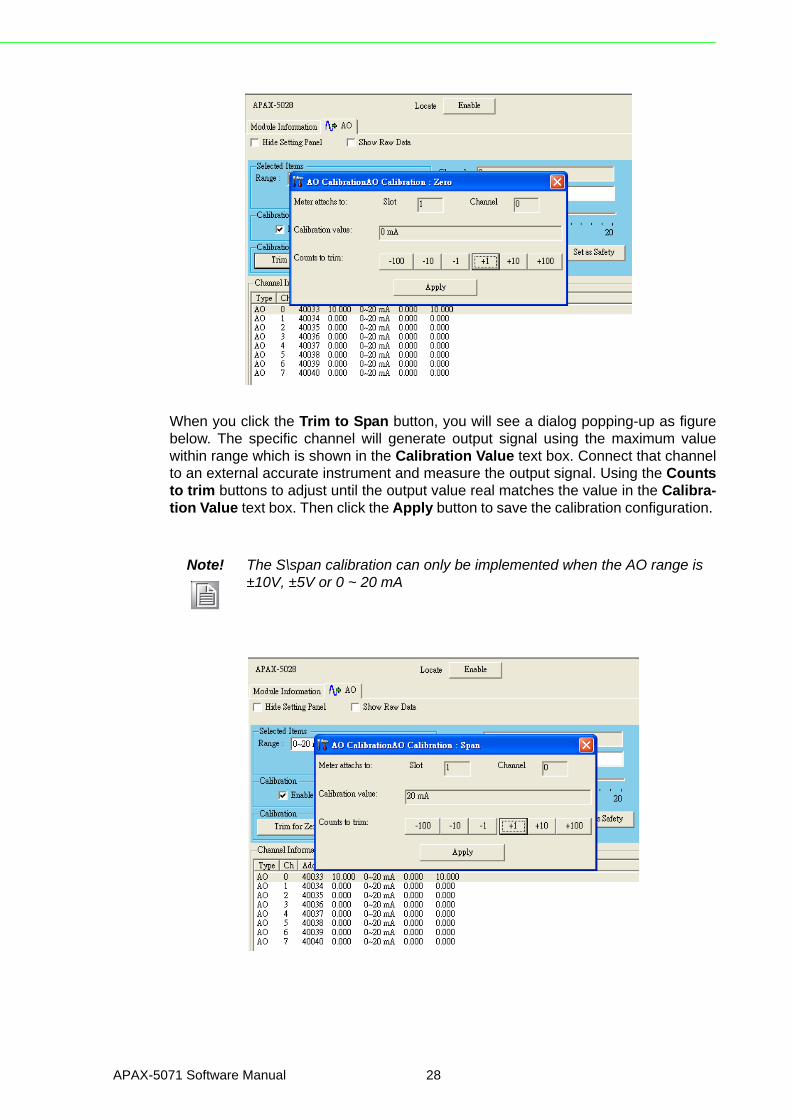
When you click the Trim to Span button, you will see a dialog popping-up as figurebelow. The specific channel will generate output signal using the maximum valuewithin range which is shown in the Calibration Value text box. Connect that channelto an external accurate instrument and measure the output signal. Using the Countsto trim buttons to adjust until the output value real matches the value in the Calibra-tion Value text box. Then click the Apply button to save the calibration configuration.
Note! The S\span calibration can only be implemented when the AO range is ±10V, ±5V or 0 ~ 20 mA
APAX-5071 Software Manual 28

Appendix A
AD
AM
/AP
AX
.NE
TU
tilityO
peration
A.3.3 Digital Input Module
There are two parts for the I/O Information tab of APAX-5000 DI module. At the bot-tom is the Channel Information Area. You can see all channels' type, Modbusaddres, value, and mode. Above the Channel Information Area is the Setting PanelArea. If you don't want see the Setting Panel Area, you can click the Hide SettingPanel check box to hide the Setting Panel Area.
APAX DI module supports digital filter functionality. Signals with period less the filterwidth will be filtered (regarding as high frequency noise). You can configure the filterwidth (acceptable pulse width). Select the channels you want to configure in theChannel Information Area (use the "Shift" or "Ctrl" key on keyboard to select multiplechannels at the same time). Type the appropriate value (unit: 0.1 ms) into the Mini-mum low signal width text box to configure acceptable minimum pulse width in theSetting Panel Area. After you complete the configuration, click the Apply button tosave the configuration.
Note! APAX-5040 is equipped with a filter which minimum period is 3 ms. Therefore, the minimum value for the Minimum low signal width text box is 30.
29 APAX-5071 Software Manual

A.3.4 Digital Output Module
There are two parts for the I/O Information tab of APAX-5000 DO module. At thebottom is the Channel Information Area. You can see all channels' type, Modbusaddress, value, mode and safety value (the default value when the communication isbroken). Above the Channel Information Area is the Setting Panel Area. If youdon't want see the Setting Panel Area, you can click the Hide Setting Panel checkbox to hide the Setting Panel Area.
If you want to change specific output channels' output value, select those channelsby clicking the channel in the Channel Information Area (use the "Shift" or "Ctrl" keyon keyboard to select multiple channels at the same time). Then define the outputvalue by the Set True button or Set False button in the Setting Panel Area. Then,click the Apply button to save the configuration. You can see the channel outputvalue changed in the Channel Information Area.
APAX-5000 output module like AO or DO module supports Fail Safety Value (FSV)function. When the output module lose its ability to communicate with controller orcoupler, all output channels will become the pre-defined value (the safety value). Youcan enable the FSV function by clicking the Enable check box in the Safety Func-tion Area.
Then, click the Set Value button to configure the safety value. A pop-up window willappear, like the figure below. You can simply type the desired safety value for eachchannel. In this example, safety value of channel 3 to 8 are "True", while other chan-nels' safety value are "False". Click the Apply button after you complete your set-tings. (You can set all channels' safety value together by clicking the check box insidethe Safety State cell.) You can see the modified safety value showing by the SafetyValue column in the Channel Information Area.
APAX-5071 Software Manual 30

Appendix A
AD
AM
/AP
AX
.NE
TU
tilityO
peration
A.3.5 Counter ModuleUsually, except counter input channels, there are also digital input and digital outputchannels for counter module like APAX-5080. So there will three I/O Information tabs(DI, DO and CNT)
(A) DI tab for digital input channels
Refer to figure below. It is similar to standard DI module's I/O Information tab (Referto Section A.3.3). At the bottom is the Channel Information Area. You can see allchannels' type, Modbus address, value, and mode.
Note! For APAX-5080, there is no digital filter for digital input channels. So you can not configure the minimum accept signal width like DI module.
31 APAX-5071 Software Manual
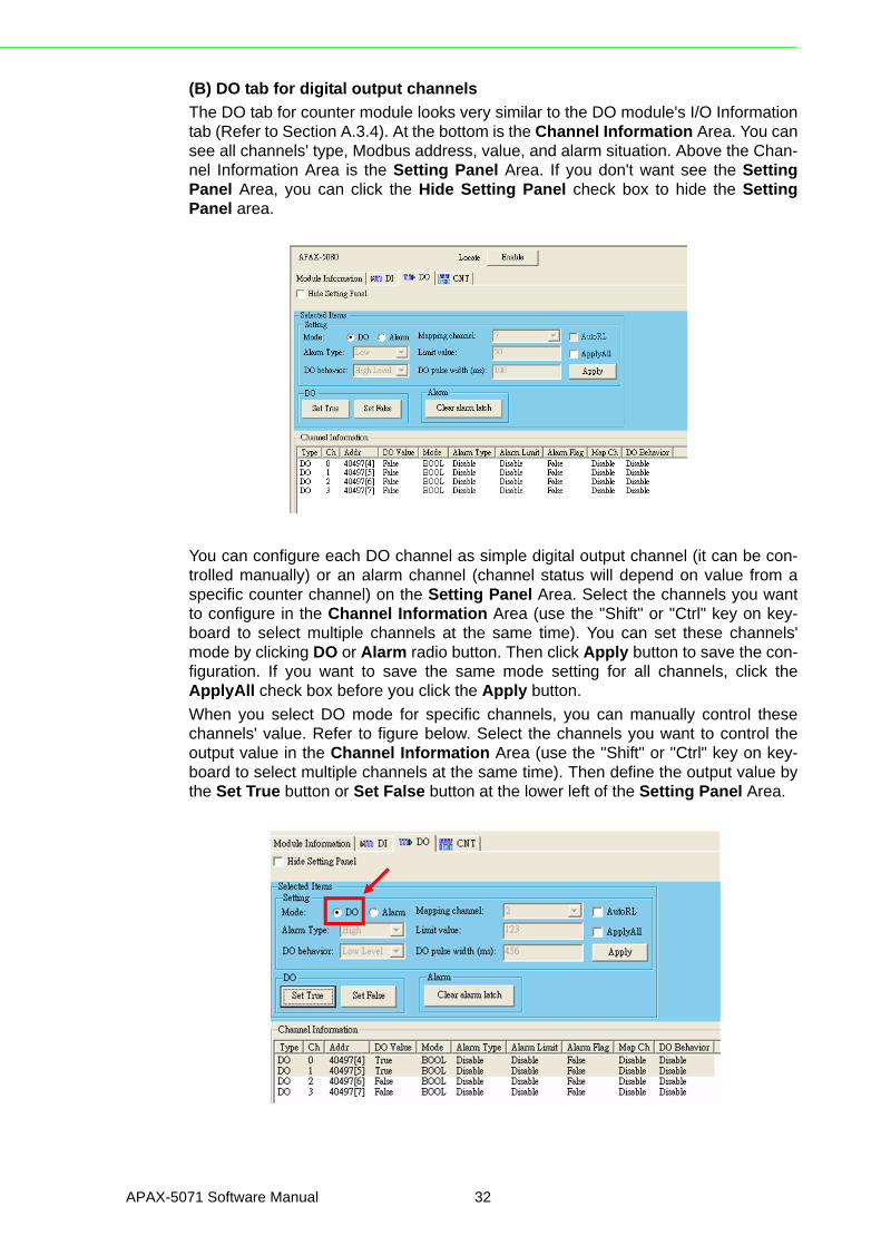
(B) DO tab for digital output channels
The DO tab for counter module looks very similar to the DO module's I/O Informationtab (Refer to Section A.3.4). At the bottom is the Channel Information Area. You cansee all channels' type, Modbus address, value, and alarm situation. Above the Chan-nel Information Area is the Setting Panel Area. If you don't want see the SettingPanel Area, you can click the Hide Setting Panel check box to hide the SettingPanel area.
You can configure each DO channel as simple digital output channel (it can be con-trolled manually) or an alarm channel (channel status will depend on value from aspecific counter channel) on the Setting Panel Area. Select the channels you wantto configure in the Channel Information Area (use the "Shift" or "Ctrl" key on key-board to select multiple channels at the same time). You can set these channels'mode by clicking DO or Alarm radio button. Then click Apply button to save the con-figuration. If you want to save the same mode setting for all channels, click theApplyAll check box before you click the Apply button.
When you select DO mode for specific channels, you can manually control thesechannels' value. Refer to figure below. Select the channels you want to control theoutput value in the Channel Information Area (use the "Shift" or "Ctrl" key on key-board to select multiple channels at the same time). Then define the output value bythe Set True button or Set False button at the lower left of the Setting Panel Area.
APAX-5071 Software Manual 32

Appendix A
AD
AM
/AP
AX
.NE
TU
tilityO
peration
When you select Alarm mode for specific channels, those channels' value will bechanged automatically based on the mapping counter input channel's value. In otherwords, the DO channel becomes alarm channel for specific counter channel. Beloware some related parameters you need to set for alarm:
1. Mapping Channel combo box: It defines which counter channel's value is used for this alarm channel (DO channel).
2. Limit value text box: The reference value to decide when an alarm happens. When the specific channel counter value is higher or lower than this limit value (depends on the Alarm Type combo box), alarm will be activated.
3. Alarm Type combo box: "High": When the counter value is higher than the reference limit value (defined by the Limit value text box), the alarm will be activated. "Low": When the counter value is lower than the reference limit value (defined by the Limit value text box), the alarm will be activated.
4. DO behavior combo box: What action that DO channel will perform when alarm is activated. "High Level": DO channel will become logic high level when alarm happens."Low Level": DO channel will become logic low level when alarm happens."High Pulse": A high pulse will be generated when alarm happens."Low Pulse": A low pulse will be generated when alarm happens.
5. DO pulse width (ms) text box: When you select "High Pulse" or "Low Pulse" for DO behavior, this parameter define the generated pulse width. (Unit: ms)
After you have complete the setting, click the Apply button to save the configuration.If you want to save the same mode setting for all channels, click the ApplyAll checkbox before you click the Apply button.
Refer to figure below. DO channel 1 is configured as alarm channel for counter inputchannel 7 (defined by the Mapping channel combo box). So as long as the countedvalue of the counter input channel 7 is greater (defined by the Alarm Type combobox) than 50 (defined by the Limit value combo box), then the alarm is activated,and the value of DO channel 1 will become logic low level (defined by the DO behav-ior combo box).
33 APAX-5071 Software Manual
Once alarm is activated, the alarm status will be latched. It won't change its value toprevious status even when alarm condition is gone. You need to manually clear thealarm to make it back to the normal status, by click the Clear alarm latch button inthe Alarm Area on the Setting Panel Area.
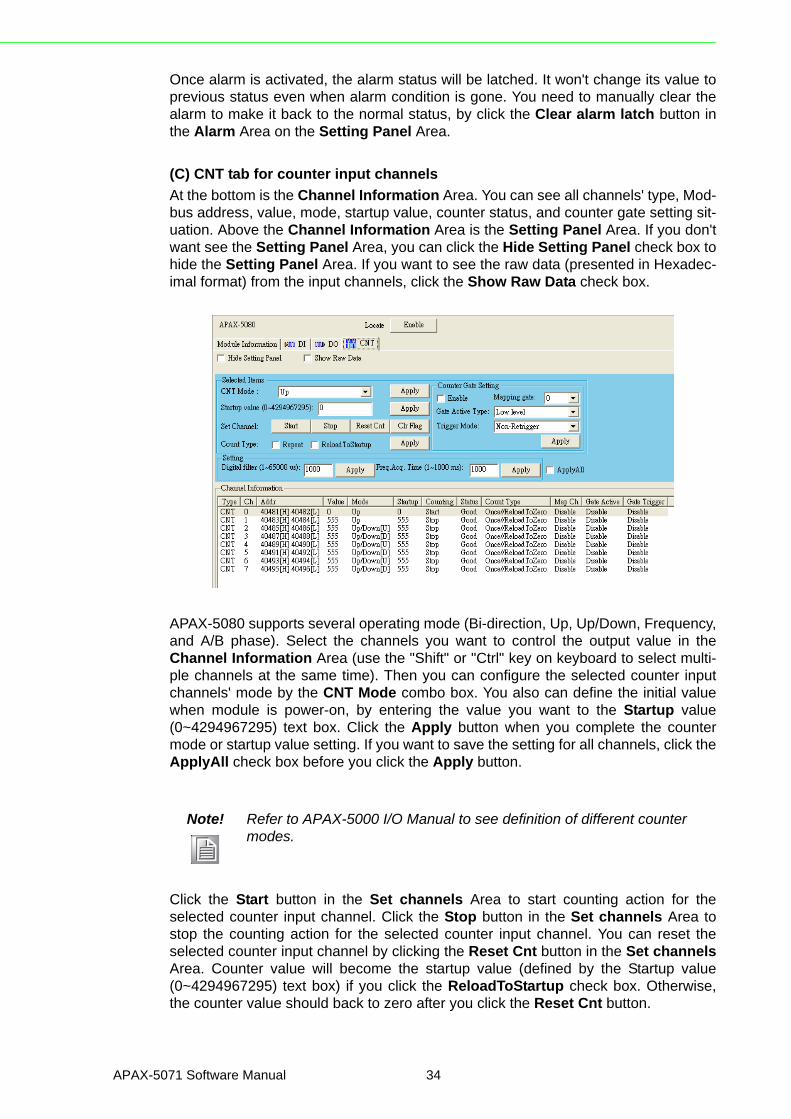
(C) CNT tab for counter input channels
At the bottom is the Channel Information Area. You can see all channels' type, Mod-bus address, value, mode, startup value, counter status, and counter gate setting sit-uation. Above the Channel Information Area is the Setting Panel Area. If you don'twant see the Setting Panel Area, you can click the Hide Setting Panel check box tohide the Setting Panel Area. If you want to see the raw data (presented in Hexadec-imal format) from the input channels, click the Show Raw Data check box.
APAX-5080 supports several operating mode (Bi-direction, Up, Up/Down, Frequency,and A/B phase). Select the channels you want to control the output value in theChannel Information Area (use the "Shift" or "Ctrl" key on keyboard to select multi-ple channels at the same time). Then you can configure the selected counter inputchannels' mode by the CNT Mode combo box. You also can define the initial valuewhen module is power-on, by entering the value you want to the Startup value(0~4294967295) text box. Click the Apply button when you complete the countermode or startup value setting. If you want to save the setting for all channels, click theApplyAll check box before you click the Apply button.
Click the Start button in the Set channels Area to start counting action for theselected counter input channel. Click the Stop button in the Set channels Area tostop the counting action for the selected counter input channel. You can reset theselected counter input channel by clicking the Reset Cnt button in the Set channelsArea. Counter value will become the startup value (defined by the Startup value(0~4294967295) text box) if you click the ReloadToStartup check box. Otherwise,the counter value should back to zero after you click the Reset Cnt button.
Note! Refer to APAX-5000 I/O Manual to see definition of different counter modes.
APAX-5071 Software Manual 34

Appendix A
AD
AM
/AP
AX
.NE
TU
tilityO
peration
When you click the Repeat check box in the Count Type Area, it means when thecounter value reaches the maximum or minimum acceptable counting value, it willrestart to count (starting from 0 or the startup value, depending on the ReloadToStar-tup check box.) Otherwise, the counter value won't change its value after reachingthe maximum or minimum acceptable counting value. Click the Apply button whenyou complete the repeating and reload to startup setting. If you want to save the set-ting for all channels, click the ApplyAll check box before you click the Apply button.
APAX counter module supports counter gate function. It means the counter action(counting or not) will be performed depending on signal value from specific digitalinput channel. Related configuration is done by the parameter in the Counter GateSetting Area. Select the channels you want to configure in the Channel InformationArea (use the "Shift" or "Ctrl" key on keyboard to select multiple channels at the sametime). Then configure the parameters listed below for the counter gate function:
1. Enable check box: Enable or disable the counter gate function.2. Mapping gate combo box: It defines which DI channel's is used (as the gate
channel) for this counter channel.3. Gate Active Type combo box: What condition when the DI channel's status
match will let the counter channel perform the counting action. "Low level": The specific counter channel will perform counting action only when the gate channel (specific DI channel) value is logic low."Falling edge": The specific counter channel will perform counting action only when a falling edge (the DI channel changes from logic high to logic low) is detected. "High level": The specific counter channel will perform counting action only when the gate channel (specific DI channel) value is logic high."Rising edge": The specific counter channel will perform counting action only when a rising edge (the DI channel changes from logic low to logic high) is detected.
4. Trigger Mode combo box: It defines if the gate can repeatedly trigger the counter channel performing counting action. Refer to figure below.
35 APAX-5071 Software Manual

APAX-5071 Software Manual 36

Appendix B
B PROFINET Address Mapping Table
B.1 PROFINET Address Mapping Table (0x)Analog Input and Analog Output Modules
Each APAX analog module will use 8 ~ 12 WORD address for its data. Each analogchannel will occupy one WORD address.
APAX-5013 Data Type Data Format Description
Inputs
Word 0 bit[15...0] Analog Input Channel_0 Value
Word 1 bit[15...0] Analog Input Channel_1 Value
Word 2 bit[15...0] Analog Input Channel_2 Value
Word 3 bit[15...0] Analog Input Channel_3 Value
Word 4 bit[15...0] Analog Input Channel_4 Value
Word 5 bit[15...0] Analog Input Channel_5 Value
Word 6 bit[15...0] Analog Input Channel_6 Value
Word 7 bit[15...0] Analog Input Channel_7 Value
APAX-5017 Data Type Data Format Description
Inputs
Word 0 bit[15...0] Analog Input Channel_0 Value
Word 1 bit[15...0] Analog Input Channel_1 Value
Word 2 bit[15...0] Analog Input Channel_2 Value
Word 3 bit[15...0] Analog Input Channel_3 Value
Word 4 bit[15...0] Analog Input Channel_4 Value
Word 5 bit[15...0] Analog Input Channel_5 Value
Word 6 bit[15...0] Analog Input Channel_6 Value
Word 7 bit[15...0] Analog Input Channel_7 Value
Word 8 bit[15...0] Analog Input Channel_8 Value
Word 9 bit[15...0] Analog Input Channel_9 Value
Word 10 bit[15...0] Analog Input Channel_10 Value
Word 11 bit[15...0] Analog Input Channel_11 Value
APAX-5017H Data Type Data Format Description
Inputs
Word 0 bit[15...0] Analog Input Channel_0 Value
Word 1 bit[15...0] Analog Input Channel_1 Value
Word 2 bit[15...0] Analog Input Channel_2 Value
Word 3 bit[15...0] Analog Input Channel_3 Value
Word 4 bit[15...0] Analog Input Channel_4 Value
Word 5 bit[15...0] Analog Input Channel_5 Value
Word 6 bit[15...0] Analog Input Channel_6 Value
Word 7 bit[15...0] Analog Input Channel_7 Value
Word 8 bit[15...0] Analog Input Channel_8 Value
Word 9 bit[15...0] Analog Input Channel_9 Value
Word 10 bit[15...0] Analog Input Channel_10 Value
Word 11 bit[15...0] Analog Input Channel_11 Value
APAX-5071 Software Manual 38

Appendix B
PR
OF
INE
TA
ddressM
apping Table
Digital Input and Digital Output Modules
Each APAX digital module will use 2~4 BYTE address for its data. Each BYTEaddress will contain 8 digital channel data.
APAX-5018 Data Type Data Format Description
Inputs
Word 0 bit[15...0] Analog Input Channel_0 Value
Word 1 bit[15...0] Analog Input Channel_1 Value
Word 2 bit[15...0] Analog Input Channel_2 Value
Word 3 bit[15...0] Analog Input Channel_3 Value
Word 4 bit[15...0] Analog Input Channel_4 Value
Word 5 bit[15...0] Analog Input Channel_5 Value
Word 6 bit[15...0] Analog Input Channel_6 Value
Word 7 bit[15...0] Analog Input Channel_7 Value
Word 8 bit[15...0] Analog Input Channel_8 Value
Word 9 bit[15...0] Analog Input Channel_9 Value
Word 10 bit[15...0] Analog Input Channel_10 Value
Word 11 bit[15...0] Analog Input Channel_11 Value
APAX-5028 Data Type Data Format Description
Outputs
Word 0 bit[15...0] Analog Output Channel_0 Value
Word 1 bit[15...0] Analog Output Channel_1 Value
Word 2 bit[15...0] Analog Output Channel_2 Value
Word 3 bit[15...0] Analog Output Channel_3 Value
Word 4 bit[15...0] Analog Output Channel_4 Value
Word 5 bit[15...0] Analog Output Channel_5 Value
Word 6 bit[15...0] Analog Output Channel_6 Value
Word 7 bit[15...0] Analog Output Channel_7 Value
APAX-5040 Data Type Data Format Description
Inputs
Byte 0 bit[7...0] Digital Input Channel[7...0] Value
Byte 1 bit[7...0] Digital Input Channel[15...8] Value
Byte 2 bit[7...0] Digital Input Channel[23...16] Value
APAX-5045 Data Type Data Format Description
InputsByte 0 bit[7...0] Digital Input Channel[7...0] Value
Byte 1 bit[3...0] Digital Input Channel[11...8] Value
OutputsByte 0 bit[7...0] Digital Output Channel[7...0] Value
Byte 1 bit[3...0] Digital Output Channel[11...8] Value
APAX-5046 Data Type Data Format Description
Outputs Byte 0 bit[7...0] Digital Input Channel[7...0] Value
Byte 1 bit[7°¦0] Digital Input Channel[15...8] Value
Byte 2 bit[7°¦0] Digital Input Channel[23...16] Value
39 APAX-5071 Software Manual

Counter Module
Each APAX counter module will use 40 BYTE address for its data. The first BYTE ofinput/output address will reserved for digital input and digital output channels. Then 8DOUBLE WORD address will be used for counter channels' value. The rest addresswill be left for other counter setting, such as counter mask, reset, overflow and under-flow, etc.
* Counter Channel Ststus for A/B Phase:
00: Normal Status
01: Error Status
* Counter Channel Ststus for others:
0: Normal Status
1: Error Status
Example: We have four APAX-5000 modules connected with APAX-5071: APAX-5017 (AI), APAX-5028 (AO), APAX-5040 (DI) and APAX-5046 (DO). So the Assem-bly Interface will be listed as below:
Input: 102 Size: 12 WORD + 3 BYTE = 27 BYTE Output: 101 Size: 8 WORD + 2 BYTE = 18 BYTE Configuration: 103 Size: 0
APAX-5060 Data Type Data Format Description
Outputs Byte 0 bit[7...0] Digital Output Channel[7...0] Value
Byte 1 bit[3...0] Digital Output Channel[11...8] Value
APAX-5080 Data Type Data Format Description
Inputs
Byte 0 bit[3...0] Digital Input Channel [3...0] Value
Double Word 1 bit[31...0] Counter Channel_0 Value
Double Word 2 bit[31...0] Counter Channel_1 Value
Double Word 3 bit[31...0] Counter Channel_2 Value
Double Word 4 bit[31...0] Counter Channel_3 Value
Double Word 5 bit[31...0] Counter Channel_4 Value
Double Word 6 bit[31...0] Counter Channel_5 Value
Double Word 7 bit[31...0] Counter Channel_6 Value
Double Word 8 bit[31...0] Counter Channel_7 Value
Byte 9 bit[7...0] Counter Channel [7°¦0] Status *
Byte 10 bit[3...0] Counter Channel [3°¦0] Alarm Status
Outputs
Byte 0 bit[3...0] Digital Output Channel [3...0] Value
Byte 1 bit[7...0] Enable Counter Channel [7°¦0]
Byte 2 bit[7...0] Reset Counter Channel [7°¦0] Value
Byte 3 bit[7...0] Clear Counter Channel [7°¦0] Status
Byte 4 bit[3...0] Clear Counter Channel [3°¦0] Alarm Status
Note! You need to change the flag value from low to high and then set it back to low to perform resetting counter channel value function. It is the same to perform clearing counter channels' overflow/underflow status and to clear counter module's alarm status.
APAX-5071 Software Manual 40

Appendix B
PR
OF
INE
TA
ddressM
apping Table
If the ID switch on the four APAX modules are set as:
APAX-5017 ID = 2
APAX-5028 ID = 1
APAX-5040 ID = 0
APAX-5046 ID = 3
Note! As we mentioned before, the ID of all APAX modules should be sequen-tial and start with 0. So if we change the APAX-5040 ID to 5, then all APAX I/O module data cannot be read back to the PROFINET master.
Category Data Type Data Format Description
Inputs
Byte 0 bit[7...0] APAX-5040 Digital Input Channel[7...0] Value
Byte 1 bit[7...0] APAX-5040 Digital Input Channel[15...8] Value
Byte 2 bit[7...0] APAX-5040 Digital Input Channel[23...16] Value
Outputs
Word 0 bit[15...0] APAX-5028 Analog Output Channel_0 Value
Word 1 bit[15...0] APAX-5028 Analog Output Channel_1 Value
Word 2 bit[15...0] APAX-5028 Analog Output Channel_2 Value
Word 3 bit[15...0] APAX-5028 Analog Output Channel_3 Value
Word 4 bit[15...0] APAX-5028 Analog Output Channel_4 Value
Word 5 bit[15...0] APAX-5028 Analog Output Channel_5 Value
Word 6 bit[15...0] APAX-5028 Analog Output Channel_6 Value
Word 7 bit[15...0] APAX-5028 Analog Output Channel_7 Value
Inputs
Word 0 bit[15...0] APAX-5017 Analog Input Channel_0 Value
Word 1 bit[15...0] APAX-5017 Analog Input Channel_1 Value
Word 2 bit[15...0] APAX-5017 Analog Input Channel_2 Value
Word 3 bit[15...0] APAX-5017 Analog Input Channel_3 Value
Word 4 bit[15...0] APAX-5017 Analog Input Channel_4 Value
Word 5 bit[15...0] APAX-5017 Analog Input Channel_5 Value
Word 6 bit[15...0] APAX-5017 Analog Input Channel_6 Value
Word 7 bit[15...0] APAX-5017 Analog Input Channel_7 Value
Word 8 bit[15...0] APAX-5017 Analog Input Channel_8 Value
Word 9 bit[15...0] APAX-5017 Analog Input Channel_9 Value
Word 10 bit[15...0] APAX-5017 Analog Input Channel_10 Value
Word 11 bit[15...0] APAX-5017 Analog Input Channel_11 Value
Outputs
Byte 0 bit[7...0] APAX-5046 Digital Input Channel[7...0] Value
Byte 1 bit[7°¦0] APAX-5046 Digital Input Channel[15...8] Value
Byte 2 bit[7°¦0] APAX-5046 Digital Input Channel[23...16] Value
41 APAX-5071 Software Manual

www.advantech.comPlease verify specifications before quoting. This guide is intended for referencepurposes only.All product specifications are subject to change without notice.No part of this publication may be reproduced in any form or by any means,electronic, photocopying, recording or otherwise, without prior written permis-sion of the publisher.All brand and product names are trademarks or registered trademarks of theirrespective companies.© Advantech Co., Ltd. 2012


![APAX 2020 Application Guide - FINAL...1 APPLICATION GUIDE About APAX PAC Australia’s national networking and development event, the Australian Performing Arts Exchange [APAX] will](https://img.dokumen.tips/doc/110x75/5f1ac4ed5db13b74c74ca4fb/apax-2020-application-guide-final-1-application-guide-about-apax-pac-australiaas.jpg)