Embed Size (px)
Citation preview

®
525ATemperature/Pressure Calibrator
Service Manual
PN 1644492March 2002© 2002 Fluke Corporation. All rights reserved. Printed in USAAll product names are trademarks of their respective companies.

LIMITED WARRANTY AND LIMITATION OF LIABILITY
Each Fluke product is warranted to be free from defects in material and workmanship undernormal use and service. The warranty period is one year and begins on the date of shipment.Parts, product repairs, and services are warranted for 90 days. This warranty extends only to theoriginal buyer or end-user customer of a Fluke authorized reseller, and does not apply to fuses,disposable batteries, or to any product which, in Fluke’s opinion, has been misused, altered,neglected, contaminated, or damaged by accident or abnormal conditions of operation orhandling. Fluke warrants that software will operate substantially in accordance with its functionalspecifications for 90 days and that it has been properly recorded on non-defective media. Flukedoes not warrant that software will be error free or operate without interruption.
Fluke authorized resellers shall extend this warranty on new and unused products to end-usercustomers only but have no authority to extend a greater or different warranty on behalf of Fluke.Warranty support is available only if product is purchased through a Fluke authorized sales outletor Buyer has paid the applicable international price. Fluke reserves the right to invoice Buyer forimportation costs of repair/replacement parts when product purchased in one country is submittedfor repair in another country.
Fluke’s warranty obligation is limited, at Fluke’s option, to refund of the purchase price, free ofcharge repair, or replacement of a defective product which is returned to a Fluke authorizedservice center within the warranty period.
To obtain warranty service, contact your nearest Fluke authorized service center to obtain returnauthorization information, then send the product to that service center, with a description of thedifficulty, postage and insurance prepaid (FOB Destination). Fluke assumes no risk for damage intransit. Following warranty repair, the product will be returned to Buyer, transportation prepaid(FOB Destination). If Fluke determines that failure was caused by neglect, misuse, contamination,alteration, accident, or abnormal condition of operation or handling, including overvoltage failurescaused by use outside the product’s specified rating, or normal wear and tear of mechanicalcomponents, Fluke will provide an estimate of repair costs and obtain authorization beforecommencing the work. Following repair, the product will be returned to the Buyer transportationprepaid and the Buyer will be billed for the repair and return transportation charges (FOBShipping Point).
THIS WARRANTY IS BUYER'S SOLE AND EXCLUSIVE REMEDY AND IS IN LIEU OF ALLOTHER WARRANTIES, EXPRESS OR IMPLIED, INCLUDING BUT NOT LIMITED TO ANYIMPLIED WARRANTY OF MERCHANTABILITY OR FITNESS FOR A PARTICULAR PURPOSE.FLUKE SHALL NOT BE LIABLE FOR ANY SPECIAL, INDIRECT, INCIDENTAL, ORCONSEQUENTIAL DAMAGES OR LOSSES, INCLUDING LOSS OF DATA, ARISING FROMANY CAUSE OR THEORY.
Since some countries or states do not allow limitation of the term of an implied warranty, orexclusion or limitation of incidental or consequential damages, the limitations and exclusions ofthis warranty may not apply to every buyer. If any provision of this Warranty is held invalid orunenforceable by a court or other decision-maker of competent jurisdiction, such holding will notaffect the validity or enforceability of any other provision.
Fluke CorporationP.O. Box 9090Everett, WA 98206-9090U.S.A.
Fluke Europe B.V.P.O. Box 11865602 BD EindhovenThe Netherlands
11/99
To register your product online, visit register.fluke.com
i
Table of Contents
Title Page
Introduction ....................................................................................................... 1Contacting Fluke ............................................................................................... 1Safety Information............................................................................................. 1Calibrator Specifications ................................................................................... 3
General Specifications .................................................................................. 3DC Voltage Specifications, Output............................................................... 4DC Current Specifications, Output ............................................................... 4Resistance Specifications, Output ................................................................. 5Resistance Specifications, Input.................................................................... 5Thermocouple Specification, Output and Input ............................................ 6TC mV Specifications, Input and Output...................................................... 7RTD and Thermistor Specification, Output .................................................. 8RTD and Thermistor Specification, Input..................................................... 9Pressure Measurement .................................................................................. 11
Theory of Operation .......................................................................................... 11Micro-Controller Section .............................................................................. 11Analog Section .............................................................................................. 12
Basic Maintenance............................................................................................. 12Cleaning the Calibrator ................................................................................. 12Replacing a Line Fuse................................................................................... 12To Check or Replace a Fuse.......................................................................... 13Changing Line Voltage ................................................................................. 13
Modular-Level Maintenance ............................................................................. 14Disassembly .................................................................................................. 15Reassembly ................................................................................................... 15
Output Block Subassembly Connections.................................................. 17Keypad to Main PCB................................................................................ 19Display Assembly to Main PCB............................................................... 19Opto RS232 to Main PCA ........................................................................ 20Reinstalling the Circuit Boards................................................................. 21Connecting the Power Module ................................................................. 21
Final Assembly and Inspection ..................................................................... 22Performance Tests ............................................................................................. 23
Required Equipment List .............................................................................. 23Testing DC Voltage....................................................................................... 24

525AService Manual
ii
Testing DC Current ....................................................................................... 25Testing Thermocouple Output ...................................................................... 26
Testing CJC (Cold Junction Compensation)............................................. 27CJC (Cold Junction Compensation) Calibration....................................... 27
Testing Thermocouple Input ......................................................................... 28Testing Ohms Output .................................................................................... 29Testing Ohms Input....................................................................................... 30Testing Pressure Modules ............................................................................. 32
Calibration Adjustment ..................................................................................... 32Initiating Communication ............................................................................. 32Starting Adjustment Mode ............................................................................ 32Adjustment Sequence.................................................................................... 33
14: Calibrate DAC, Digital to Analog Converter Adjustment.................. 341: 100 mV Source to 4: 100 V Source, Adjusting DC Source.................. 345: 100 mA Source, Adjusting DC Current Source.................................... 356: Hi Ohms Source, Adjusting High Resistance Source........................... 377: Low Ohms, Adjusting Low Ohms Source............................................ 388: Hi Ohms, Adjusting High Resistance Measure .................................... 389: Low Ohms, Adjusting Low Resistance Measure.................................. 4010: SPRT 25, Adjusting SPRT Low Resistance Measure ........................ 4111: TC SOURCE, Adjusting TC mVolt Source ....................................... 4312: TC Read, Adjusting TC mVolt Measure ............................................ 43
Customer Replaceable Parts .............................................................................. 45
iii
List of Tables
Table Title Page
1. Symbols Used on the Calibrator ............................................................................ 22. Replacement Fuses ................................................................................................ 133. Front Panel Wire Color Assignments .................................................................... 164. Rear Panel Wire Color Assignments ..................................................................... 165. Output Block to Main PCA Connections............................................................... 176. TC PCA to Main PCA Connections ...................................................................... 187. Opto RS232 to Main PCA Connections ................................................................ 208. Power Module to Main PCA Connections............................................................. 219. Power Connections ................................................................................................ 2210. Required Equipment .............................................................................................. 2311. Testing DC Voltage ............................................................................................... 2413. TC Temperatures ................................................................................................... 2614. Ohms Output Ranges ............................................................................................. 2915. Ohms Ratio Table .................................................................................................. 3116. Calibration Dependencies ...................................................................................... 3317. List of Equipment for Voltage Calibration Adjustments ....................................... 3418. List of Equipment for Current Calibration Adjustments ....................................... 3519. List of Equipment for High Ohms Measure Calibration Adjustments .................. 3820. List of Equipment for High Ohms Measure Calibration Adjustments .................. 4021. List of Equipment for Low Ohms Measure Calibration Adjustments ................... 4122. List of Test Equipment for Adjusting TC Source .................................................. 4323. List of Test Equipment for Adjusting TC Read..................................................... 4324. List of Test Equipment for Adjusting TC CJC ...................................................... 4525. Replacement Parts.................................................................................................. 4726. Accessories ............................................................................................................ 48

525AService Manual
iv

v
List of Figures
Figure Title Page
1. Accessing the Fuse................................................................................................. 142. Wiring Connections ............................................................................................... 173. Solder Connections for the TC PCA...................................................................... 184. Keypad PCA Connections ..................................................................................... 195. Connections for the Opto RS232 PCA .................................................................. 206. Power Module Connections................................................................................... 227. Measuring DC Current........................................................................................... 258. Testing TC Output ................................................................................................. 269. Connections for CJC Calibration ........................................................................... 2710. Connections for Measuring TC Input .................................................................... 2811. Connection for Measuring Resistance Output ....................................................... 2912. 1281 Connection Diagram ..................................................................................... 3013. Connection for Measuring Ohms........................................................................... 3114. Exploded View of the 525A .................................................................................. 46

525AService Manual
vi
1
525A
IntroductionThis manual provides user-service information for the 525A Temperature/PressureCalibrator (hereafter referred to as "the Calibrator"). Details regarding verification of theCalibrator’s functionality and calibration, basic maintenance, contacting Fluke servicecenters, and important safety information are also contained within this manual.
Contacting FlukeTo contact Fluke, order accessories, or locate the nearest Fluke Service Center ordistributor, call:
• USA: 1-888-99-FLUKE (1-888-993-5853)• Canada: 1-800-36-FLUKE (1-800-363-5853)• Europe: +31-402-678-200• Japan: +81-3-3434-0181• Singapore: +65-738-5655• Anywhere in the world: +1-425-446-5500
Or, visit Fluke’s Web site at www.fluke.com.
Safety InformationThe Calibrator complies with EN 61010, ANSI/ISA-S82.01-1994, and CAN/CSA-C22.2No. 1010.1-92. Use the Calibrator only as specified in this manual, otherwise theprotection provided by the Calibrator may be impaired.
CAT II equipment is designed to protect against transients from energy-consumingequipment supplied from a fixed installation, such as televisions, personal computers,portable tools, and other household appliances.
A “WWarning” statement identifies hazardous conditions and actions that could causebodily harm or death.
A “WCaution” statement identifies conditions and actions that could damage theCalibrator or the equipment under test.
International symbols used on the Calibrator and in this manual are explained in Table 1.

525AService Manual
2
WWarningTo avoid possible electric shock or personal injury, follow these guidelines:
• Use the Calibrator only as specified in this manual or the protection provided by theCalibrator might be impaired.
• Inspect the Calibrator before use. Do not use the Calibrator if it appears damaged.Look for cracks or missing plastic. Pay particular attention to the insulation aroundthe connectors.
• Have the Calibrator serviced only by qualified service personnel.
• Do not apply more than the rated voltage between the terminals, as marked on theCalibrator, or between any terminal and earth ground.
• Always use the power cord and connector appropriate for the voltage and outlet ofthe country or location in which you are working.
• Never operate the Calibrator with the cover removed or the case open.
• Never remove the cover or open the case of the Calibrator without first removing thepower source.
• Use caution when working with voltages above 30 V ac rms, 42 V ac peak, or60 V dc. These voltages pose a shock hazard.
• Use only the replacement fuse(s) specified in this manual.
• Use the proper terminals, function, and range for your measurements.
• Do not operate the Calibrator around explosive gas, vapor, or dust.
• When servicing the Calibrator, use only specified replacement parts.
Table 1. Symbols Used on the Calibrator
AC (Alternating Current) Earth ground
DC (Direct Current) Ω Resistance
Pressure Conforms to European Union directives
Chassis protective ground Canadian Standards Association,NRTL
Important Information. Refer to themanual.
International ON/OFF symbol.
Caution, risk of electric shock

525ACalibrator Specifications
3
Calibrator Specifications
General Specifications
Warm up time Twice the time since last warmed up, to a maximum of 30 minutes
Settling time Less than 5 seconds for all functions and ranges except as noted
Standard interface RS-232
Optional interface IEEE-488 (GPIB)
Temperature performance Operating 0 °C to 50 °CCalibration (tcal) 18 °C to 28 °CStorage -20 °C to 70 °C
Electromagnetic compatibility CE: Conforms to EN61326
Temperature coefficient Temperature coefficient for temperatures outside tcal ±5 °C is10 % of the 90 day specification (or 1 year if applicable) per °C
Relative humidity Operating < 80 % to 30 °C, < 70 % to 40 °C, < 40 % to 50 °CStorage < 95 % noncondensing
Altitude Operating 3,050 m (10,000 ft) maximumNonoperating 12,200 m (40,000 ft) maximum
Safety EN 61010 Second, ANSI/ISA-S82.01-1994,CAN/CSA-C22.2 No. 1010.1-92, NRTL
Analog low isolation 20 V
Line power Line Voltage (selectable) 100 V/120 V or 220 V/240 VLine Frequency 47 to 63 HzLine Voltage Variation ±10 % about line voltage setting
Power consumption 15 VA maximum
Dimensions Height 13.3 cm (5.25 in) plus 1.5 cm (0.6 in) four feet on bottomWidth ¾ standard rack widthDepth 47.3 cm (18.6 in) overall
Weight (without options) 4 kg (9 lb)
525AService Manual
4
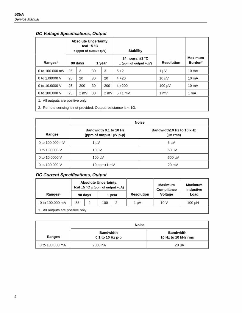
DC Voltage Specifications, Output
Absolute Uncertainty,tcal ±5 °C
± (ppm of output +µV) Stability
Ranges1 90 days 1 year24 hours, ±1 °C
± (ppm of output +µV) ResolutionMaximumBurden2
0 to 100.000 mV 25 3 30 3 5 +2 1 µV 10 mA
0 to 1.00000 V 25 20 30 20 4 +20 10 µV 10 mA
0 to 10.0000 V 25 200 30 200 4 +200 100 µV 10 mA
0 to 100.000 V 25 2 mV 30 2 mV 5 +1 mV 1 mV 1 mA
1. All outputs are positive only.
2. Remote sensing is not provided. Output resistance is < 1Ω.
Noise
RangesBandwidth 0.1 to 10 Hz(ppm of output +µV p-p)
Bandwidth10 Hz to 10 kHz(µV rms)
0 to 100.000 mV 1 µV 6 µV
0 to 1.00000 V 10 µV 60 µV
0 to 10.0000 V 100 µV 600 µV
0 to 100.000 V 10 ppm+1 mV 20 mV
DC Current Specifications, Output
Absolute Uncertainty,tcal ±5 °C ± (ppm of output +µA)
Ranges1 90 days 1 year Resolution
MaximumCompliance
Voltage
MaximumInductive
Load
0 to 100.000 mA 85 2 100 2 1 µA 10 V 100 µH
1. All outputs are positive only.
Noise
RangesBandwidth
0.1 to 10 Hz p-pBandwidth
10 Hz to 10 kHz rms
0 to 100.000 mA 2000 nA 20 µA

525ACalibrator Specifications
5
Resistance Specifications, Output
Absolute Uncertainty,tcal ±5 °C,
±(ppm of output ± Ω)Ranges1
90 days 1 yearResolution Allowable Current2
5 to 400.00 Ω 0.025 0.03 0.01 Ω 1 to 10 mA
5 to 4.0000 kΩ 0.25 0.3 0.1 Ω 250 µA to 1 mA
1. Continuously variable from 0 to 4 kΩ.
2. For currents lower than shown, the floor adder increases by Floor(new) = Floor(old) x Imin/Iactual.For example, a 500 µA stimulus measuring 100 Ω has a floor uncertainty of 0.025 Ω x 1 mA/500 µA =0.05 Ω.
Resistance Specifications, Input
Absolute Uncertainty,tcal ±5 °C, ±(ppm of output ± Ω)
Ranges 90 days 1 year Resolution Stimulus Current
0 to 400.00 Ω 35 0.003 40 0.003 0.001 Ω 1 mA
401 to 4001.00 Ω 35 0.03 40 0.03 0.01 Ω 0.1 mA

525AService Manual
6
Thermocouple Specification, Output and Input
Absolute Uncertainty,tcal ±5 °C, ±(°C)1
Range (°C) Output/Input
TC Type Minimum Maximum 90 days 1 year
B 600 °C800 °C1000 °C1550 °C
800 °C1000 °C1550 °C1820 °C
0.42 °C0.39 °C0.40 °C0.44 °C
0.46 °C0.39 °C0.40 °C0.45 °C
C 0 °C150 °C650 °C1000 °C1800 °C
150 °C650 °C1000 °C1800 °C2316 °C
0.25 °C0.21 °C0.23 °C0.38 °C0.63 °C
0.30 °C0.26 °C0.31 °C0.50 °C0.84 °C
E -250 °C-100 °C-25 °C350 °C650 °C
-100 °C-25 °C350 °C650 °C1000 °C
0.38 °C0.16 °C0.14 °C0.14 °C0.16 °C
0.50 °C0.18 °C0.15 °C0.16 °C0.21 °C
J -210 °C-100 °C-30 °C150 °C760 °C
-100 °C-30 °C150 °C760 °C1200 °C
0.20 °C0.18 °C0.14 °C0.14 °C0.18 °C
0.27 °C0.20 °C0.16 °C0.17 °C0.23 °C
K -200 °C-100 °C-25 °C120 °C1000 °C
-100 °C-25 °C120 °C1000 °C1372 °C
0.25 °C0.19 °C0.14 °C0.19 °C0.30 °C
0.33 °C0.22 °C0.16 °C0.26 °C0.40 °C
L -200 °C-100 °C800 °C
-100 °C800 °C900 °C
0.37 °C0.26 °C0.17 °C
0.37 °C0.26 °C0.17 °C
N -200 °C-100 °C-25 °C120 °C410 °C
-100 °C-25 °C120 °C410 °C1300 °C
0.33 °C0.20 °C0.16 °C0.14 °C0.21 °C
0.40 °C0.24 °C0.19 °C0.18 °C0.27 °C
1. Does not include thermocouple wire error.

525ACalibrator Specifications
7
Thermocouple Specification, Output and Input (continued)
Absolute Uncertainty,tcal ±5 °C, ±(°C)1
Range (°C) Output/Input
TC Type Minimum Maximum 90 days 1 year
R 0 °C250 °C400 °C1000 °C
250 °C400 °C1000 °C1750 °C
0.58 °C0.34 °C0.31 °C0.30 °C
0.58 °C0.35 °C0.33 °C0.40 °C
S 0 °C250 °C1000 °C1400 °C
250 °C1000 °C1400 °C1750 °C
0.56 °C0.36 °C0.30 °C0.35 °C
0.56 °C0.36 °C0.37 °C0.46 °C
T -250 °C-150 °C0 °C120 °C
-150 °C0 °C120 °C400 °C
0.51 °C0.18 °C0.13 °C0.12 °C
0.63 °C0.24 °C0.16 °C0.14 °C
U -200 °C0 °C
0 °C600 °C
0.56 °C0.27 °C
0.56 °C0.27 °C
mV -10 to 75.000 mV
1. Does not include thermocouple wire error.
TC mV Specifications, Input and OutputAbsolute Uncertainty,
tcal +/-5 °C+/-( ppm of output + µV)
Range(mV) 90 Days 1 Year
Stability24 Hours +/-1°C
+/- ( ppm of output + µV) ResolutionMaximum
Burden
-10 to75.000
25 + 3µV 30 + 3µV 5 + 2µV 1µV 10 Ohms

525AService Manual
8
RTD and Thermistor Specification, Output
Range (°C)Absolute Uncertainty
tcal ±5 °C, ±(°C)1
RTD Type Minimum Maximum 90 days 1 year
Pt 385, 100 Ω -200 °C-80 °C0 °C100 °C300 °C400 °C630 °C
-80 °C0 °C100 °C300 °C400 °C630 °C800 °C
0.06 °C0.08 °C0.08 °C0.07 °C0.07 °C0.08 °C0.08 °C
0.07 °C0.10 °C0.10 °C0.09 °C0.09 °C0.09 °C0.10 °C
Pt 3926, 100 Ω -200 °C-80 °C0 °C100 °C300 °C400 °C
-80 °C0 °C100 °C300 °C400 °C630 °C
0.06 °C0.06 °C0.06 °C0.07 °C0.07 °C0.08 °C
0.07 °C0.07 °C0.08 °C0.08 °C0.09 °C0.09 °C
Pt 3916, 100 Ω -200 °C-190 °C-80 °C0 °C100 °C260 °C300 °C400 °C600 °C
-190 °C-80 °C0 °C100 °C260 °C300 °C400 °C600 °C630 °C
0.06 °C0.06 °C0.06 °C0.06 °C0.07 °C0.07 °C0.07 °C0.08 °C0.08 °C
0.07 °C0.08 °C0.08 °C0.08 °C0.08 °C0.08 °C0.09 °C0.09 °C0.09 °C
Pt 385, 200 Ω -200 °C-80 °C0 °C100 °C260 °C300 °C400 °C600 °C
-80 °C0 °C100 °C260 °C300 °C400 °C600 °C630 °C
0.31 °C0.32 °C0.33 °C0.33 °C0.36 °C0.36 °C0.42 °C0.42 °C
0.38 °C0.38 °C0.39 °C0.39 °C0.43 °C0.43 °C0.50 °C0.50 °C
Pt 385, 500 Ω -200 °C-80 °C0 °C100 °C260 °C300 °C400 °C600 °C
-80 °C0 °C100 °C260 °C300 °C400 °C600 °C630 °C
0.13 °C0.13 °C0.13 °C0.14 °C0.14 °C0.15 °C0.16 °C0.16 °C
0.15 °C0.15 °C0.16 °C0.17 °C0.17 °C0.18 °C0.19 °C0.19 °C
1. 2-wire output

525ACalibrator Specifications
9
RTD and Thermistor Specification, Output (continued)
Range (°C)Absolute Uncertainty
tcal ±5 °C, ±(°C)1
RTD Type Minimum Maximum 90 days 1 year
Pt 385, 1000 Ω -200 °C-80 °C0 °C100 °C260 °C300 °C400 °C600 °C
-80 °C0 °C100 °C260 °C300 °C400 °C600 °C630 °C
0.06 °C0.06 °C0.07 °C0.07 °C0.07 °C0.07 °C0.08 °C0.08 °C
0.07 °C0.08 °C0.08 °C0.08 °C0.09 °C0.09 °C0.09 °C0.09 °C
PtNi 385, 120 Ω(Ni 120)
-80 °C0 °C100 °C
0 °C100 °C260 °C
0.04 °C0.04 °C0.03 °C
0.05 °C0.04 °C0.03 °C
Cu 427, 10 Ω2 -100 °C 260 °C 0.63 °C 0.75 °C
YSI 400 15 °C 50 °C 0.005 °C 0.007 °C
1. 2-wire output
2. Based on MINCO Application Aid No. 18.
RTD and Thermistor Specification, Input
Range (°C)Absolute Uncertainty,
tcal ±5 °C, ±(°C)1
RTD Type Minimum Maximum 90 days 1 year
Pt 385, 100 Ω -200 °C-80 °C0 °C100 °C300 °C400 °C630 °C
-80 °C0 °C100 °C300 °C400 °C630 °C800 °C
0.031 °C0.018 °C0.018 °C0.027 °C0.031 °C0.042 °C0.050 °C
0.012 °C0.020 °C0.020 °C0.030 °C0.035 °C0.047 °C0.057 °C
Pt 3926, 100 Ω -200 °C-80 °C0 °C100 °C300 °C400 °C
-80 °C0 °C100 °C300 °C400 °C630 °C
0.031 °C0.014 °C0.018 °C0.026 °C0.031 °C0.041 °C
0.031 °C0.015 °C0.019 °C0.029 °C0.034 °C0.046 °C
Pt 3916, 100 Ω -200 °C-190 °C-80 °C0 °C100 °C260 °C300 °C400 °C600 °C
-190 °C-80 °C0 °C100 °C260 °C300 °C400 °C600 °C630 °C
0.026 °C0.011 °C0.014 °C0.018 °C0.025 °C0.026 °C0.031 °C0.040 °C0.042 °C
0.028 °C0.012 °C0.015 °C0.019 °C0.028 °C0.029 °C0.034 °C0.045 °C0.047 °C
Pt 385, 200 Ω -200 °C-80 °C0 °C100 °C260 °C300 °C400 °C600 °C
-80 °C0 °C100 °C260 °C300 °C400 °C600 °C630 °C
0.071 °C0.075 °C0.079 °C0.082 °C0.090 °C0.093 °C0.100 °C0.101 °C
0.072 °C0.076 °C0.081 °C0.085 °C0.093 °C0.097 °C0.105 °C0.106 °C
1. 4-wire mode. Uncertainties listed do not include probe uncertainties.

525AService Manual
10
RTD and Thermistor Specification, Input (continued)
Range (°C)Absolute Uncertainty,
tcal ±5 °C, ±(°C)1
RTD Type Minimum Maximum 90 days 1 year
Pt 385, 500 Ω -200 °C-80 °C0 °C100 °C260 °C300 °C400 °C600 °C
-80 °C0 °C100 °C260 °C300 °C400 °C600 °C630 °C
0.046 °C0.049 °C0.043 °C0.030 °C0.032 °C0.037 °C0.047 °C0.048 °C
0.047 °C0.050 °C0.045 °C0.033 °C0.035 °C0.041 °C0.052 °C0.076 °C
Pt 385, 1000 Ω -200 °C-80 °C0 °C100 °C260 °C300 °C400 °C600 °C
-80 °C0 °C100 °C260 °C300 °C400 °C600 °C630 °C
0.031 °C0.034 °C0.039 °C0.025 °C0.027 °C0.030 °C0.041 °C0.042 °C
0.032 °C0.035 °C0.040 °C0.028 °C0.030 °C0.034 °C0.045 °C0.047 °C
PtNi 385, 120 Ω(Ni120)
-80 °C0 °C100 °C
0 °C100 °C260 °C
0.209 °C0.210 °C0.211 °C
0.210 °C0.211 °C0.212 °C
Cu 427, 10 Ω2 -100 °C 260 °C 0.300 °C 0.069 °C
YSI 400 15 °C 50 °C 0.005 °C 0.304 °C
SPRT, 25 Ω User Defined User Defined 0.05 °C 0.06 °C
1. 4-wire mode. Uncertainties listed do not include probe uncertainties.
2. Based on MINCO Application Aid No. 18.

525ATheory of Operation
11
Pressure MeasurementThe Calibrator can accept either the Fluke 700 or 6100 series pressure modules. Pressuremodules plug directly into the front panel Lemo connector. The Calibrator firmwareautomatically detects the type and value of the module you are attaching, and recognizesthe following units of measurement:
• PSI(pounds per square inch)
• inH2O4°C(inches of water at 4 degrees Celsius)
• inH2O20C(inches of water at 20 degrees Celsius)
• cmH2O4°C(centimeters of water at 4 degrees Celsius)
• cmH2O20C(centimeters of water at 20 degrees Celsius)
• BAR(bars)
• mBAR(millibars)
• KPAL(kilopascals)
• inHG 0°C(inches of mercury at 0 degrees Celsius)
• mmHG 0°C(millimeters of mercury at 0 degreesCelsius)
• Kg/cm2(kilograms per square centimeter)
Theory of OperationThe Calibrator serves as an accurate laboratory device for calibrating thermocouples,RTDs, pressure devices, and low-level dc voltages and currents. The main PCBassembly, and several subassemblies, work together to provide high-reliability and easymaintenance.
Micro-Controller SectionThe Atmel ATmega 103 micro-controller is the heart of the 525A. It contains all of theprogram memory, nv-ram, FlashROM, static RAM, and EEProm. The micro-controllerallows a minimal amount of external glue logic. The main external digital ICs are the RS-232 driver, relay drivers, LCD controller, and the digitally controlled analog switches.Many of the ICs are interfaced through the micro-controller’s three-wire SPI busminimizing interconnecting lines. Inputs or outputs begin with instructions enteredthrough the keypad or through remote communications (serial or IEEE-488) into themicro-controller. The micro-controller processes the commands and sets conditions thatare appropriate for the command.
525AService Manual
12
Analog SectionThe Calibrator can source DC voltage to 100 V, DC current to 100 mA, resistances from 5 to4000 Ω, and thermocouples and RTDs. The main components of the analog circuit consist of aprecision 2.5-volt temperature compensated reference, 20-bit DAC and a 24-bit ADC. Precisionmetal foil resistor networks and several chopper-stabilized OP-AMPS are the most critical analogcomponents.
When sourcing, the micro-controller, using stored calibration constants, adjusts the D/A togenerate an output based on the function and range selected. To achieve high accuracy, a low drift24-bit A/D converter is used as a feedback element near the output of the D/A converter. Thescaled output DAC_CK is routed to the A/D converter.
In the input mode, the A/D is used directly to measure either the T/C or the resistance (RTD)inputs. The A/D features an internal self-calibration function that continually nulls out zero driftdue to temperature changes. A programmable gain stage in the A/D is adjusted by the micro-controller to allow direct T/C and RTD inputs without requiring external amplification. In theRTD mode, a constant current source is used to excite the RTD and the voltage developed acrossthe RTD is measured by the A/D, then the resistance can be calculated.
Basic MaintenanceW Warning
To avoid personal injury or damage to the Calibrator, use onlythe specified replacement parts and do not allow water into thecase.
Cleaning the Calibrator
WCautionTo avoid damaging the case, do not use solvents or abrasivecleaners.
Clean the Calibrator and pressure modules with a soft cloth dampened with water or mildsoap and water.
Replacing a Line Fuse
W WarningTo avoid electrical shock, disconnect line power before openingthe case or line voltage selector.
The line power fuses and line voltage selector switch are located in a compartment abovethe power switch on the right rear of the Calibrator. The fuse-rating label on the rearpanel shows the correct replacement fuse for each line voltage setting.
Table 2 lists the fuse part numbers for each line voltage setting. Figure 1 shows how toremove the fuse compartment cover.

525ABasic Maintenance
13
To Check or Replace a Fuse1. Disconnect line power.
2. Using a flat-blade screwdriver, pry the tab at the base of the line fuse compartment.The compartment cover will pop part way out.
3. Remove the compartment cover. The fuses come out with the compartment cover andcan easily be checked or replaced.
4. To reinstall the fuse, push the compartment cover back into the compartment until thetab locks in place.
NoteWhen changing the line voltage setting, make sure to verify that theappropriate line fuse is installed in the Calibrator. Replace the fuse asrequired.
Table 2. Replacement Fuses
Part Number Fuse Description Line Voltage Setting
1645311 W Fuse, 0.25 A fast fuse 120 V (90 V to 132 V)
1645327 W Fuse, 0.125 A fast fuse 240 V (198 V to 264 V)
Changing Line VoltageThe Calibrator arrives from the factory configured for the line voltage appropriate for thecountry of purchase or as specified when it is ordered. To verify the line voltage setting,check the line voltage indicator on the line power fuse compartment cover.
NoteConfirm that the line voltage selection is set for 120 V for line voltagesbetween 90 V and 132 V or that the selector is set to 240 V for line voltagesbetween 198 V and 264 V.
To change the line voltage:
1. Disconnect line power.
2. Using a flat-blade screwdriver, pry the tab at the base of the line fuse compartment.The compartment cover will pop part way out.
3. Remove the compartment cover.
4. Remove the line voltage selector assembly by gripping the line voltage indicator tabwith pliers and pulling it straight out of the compartment.
5. Rotate the line voltage selector assembly to the desired voltage and reinsert.
6. Verify the appropriate fuse is being used for the selected line voltage (see Table 2)and reinstall the fuse compartment by pushing it in until the tab locks in place.

525AService Manual
14
0V
(SB
)
12
0V
12
0
Changing line voltage
Changing line fuse
Line voltage indicator
Line fusecompartment
Rotate to changeline voltage indicator
24
0V
ajr12f.eps
Figure 1. Accessing the Fuse
Modular-Level MaintenanceXWarning
Do not attempt to complete the following procedures unlessqualified to do so. This information is for use by qualifiedpersonnel only.
WCautionWhen making solder connections, use "no clean" solder.
At some point in time, it may be necessary to perform modular-level maintenance ortroubleshooting of the Calibrator.
525AModular-Level Maintenance
15
Evaluation of most problems can be made after the top cover is removed. Inside thechassis are six circuit boards. They are connected to one another with point to pointwiring. The six circuit boards are the Main PCA, Keypad PCA, TC PCA, Lemo PCA,Opto RS232 PCA, and the Display PCA.
Most of the Calibrator circuitry is located on the Main PCA. The Display PCA, KeypadPCA, and Lemo PCA are mounted to the front of the chassis. The TC PCA is mounted inthe Output Block, and the Opto RS232 PCA is mounted on the rear of the chassis.
If the Main PCA needs repair, it is recommended that all other circuit boards be removedfrom the chassis still assembled. Repair of the other circuit boards can be accomplishedwhile leaving them inside the chassis.
DisassemblyTo open the Calibrator case, remove the six screws from each end and lift off the topcover.
To remove all of the circuit boards while still assembled, do the following:
1. Stand the chassis on the front handles.
2. Remove the four nylon screws that attach the Display PCA to the front.
3. Remove the six screws that attach the Keypad PCA to the front.
4. Remove the five nuts that attach the Output Block to the front.
5. Remove the standoff nuts from the 9-pin D connector on the Opto RS232 PCA, ifpresent.
6. Stand the 525A back on its feet.
7. Remove the screws attaching the Opto RS232 PCA to the back, if present.
8. Remove the four screws through the transformer.
9. Remove the six screws that attach the Main PCA to the chassis base.
10. Carefully lift all of the attached circuit boards out of the chassis.
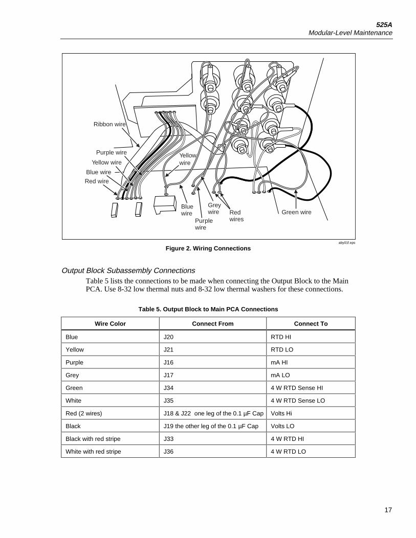
ReassemblyIt is easier to solder the wires interconnecting the circuit boards before placing theassemblies back into the chassis. The procedures in this section will explain how toreconnect each of the circuit boards.
There are two wire sets available from Fluke. These wire sets are used to connect thecircuit boards. One set is for the front connections and the other set is for the rear panelconnections. Refer to Figure 2 for wire locations and Tables 3 and 4 for the detailed listof front and rear panel connections.

525AService Manual
16
Table 3. Front Panel Wire Color Assignments
Wire Number ColorGage
(all lengths are 6 inches)
J5 Red 24 g Wire
J7 Black 24 g Wire
J16 Purple 20 g Wire *
J 17 Grey 20 g Wire *
J18 (1st 6 inches) Red 20 g Wire *
J19 Black 20 g Wire *
J20 Blue 20 g Wire *
J21 Yellow 20 g Wire *
J22 (2nd six inches) Red 20 g Wire *
J33 White/Red 20 g Wire *
J34 Green 20 g Wire *
J35 White 20 g Wire *
J36 Black/Red 20 g Wire *
* Connect With Terminal Lug
Table 4. Rear Panel Wire Color Assignments
Wire Number ColorGage
(all lengths are 6 inches)
AC3 Red 20 g Wire*
AC4 White 20 g Wire*
AC7 Red 20 g Wire *
AC8 Green 20 g Wire *
AC9 Black 20 g Wire *
AC10 White 20 g Wire *
* Connect With Spade Lug
525AModular-Level Maintenance
17
Green wire
Red wire
Blue wire
Blue wire
Purple wire
Grey wire Red
wires
Yellow wireYellow wire
Purple wire
Ribbon wire
aby01f.eps
Figure 2. Wiring Connections
Output Block Subassembly ConnectionsTable 5 lists the connections to be made when connecting the Output Block to the MainPCA. Use 8-32 low thermal nuts and 8-32 low thermal washers for these connections.
Table 5. Output Block to Main PCA Connections
Wire Color Connect From Connect To
Blue J20 RTD HI
Yellow J21 RTD LO
Purple J16 mA HI
Grey J17 mA LO
Green J34 4 W RTD Sense HI
White J35 4 W RTD Sense LO
Red (2 wires) J18 & J22 one leg of the 0.1 µF Cap Volts Hi
Black J19 the other leg of the 0.1 µF Cap Volts LO
Black with red stripe J33 4 W RTD HI
White with red stripe J36 4 W RTD LO

525AService Manual
18
The TC PCA needs to be connected to the Main PCA. Use the wire connections listed inTable 6. These connections require soldering. Refer to Figure 3.
Table 6. TC PCA to Main PCA Connections
Wire ColorSolder From TC PCA
(from left to right) Solder To Main PCA
Red 1st wire pad J23
Black 2nd wire pad J24
Blue 3rd wire pad J25
Yellow 4th wire pad J26
White 5th wire pad J27
Purple 6th wire pad J28
Purple wireYellow wire
Blue wireRed wire
Ribbon cable
aby02f.eps
Figure 3. Solder Connections for the TC PCA

525AModular-Level Maintenance
19
Keypad PCA to Main PCATo connect the Keypad PCA to the Main PCA, solder the following connections (refer toFigure 4):
1. Solder the 12-conductor cable to the back of the Keypad PCA with pin 1 on the cablealigned with pin 1 on the Keypad PCA.
2. Solder the Keypad ribbon cable to J11 with pin 1 lined up with the square hole inJ11.
Ribbon cables
aby03f.eps
Figure 4. Keypad PCA Connections
Display Assembly to Main PCATo attach the Display Assembly to the Main PCA, make the following connections:
1. Solder a red wire from J5 on the Main PCA to the "A" hole in the Display PCA.
2. Solder a black wire from J7 on the Main PCA to the "K" hole in the Display PCA.
3. Solder the 14-connector cable to the back of the Display PCA with pin 1 on the cablealigned with pin 1 on the Display PCA.
4. Solder the 14-conductor ribbon cable to the LCD Display (J4) position on the rightside of the Main PCA with pin 1 in the square hole in J4.

525AService Manual
20
Opto RS232 PCA to Main PCAUse 4 wires to connect the Opto RS232 PCA to the Main PCA. Refer to Table 7 andFigure 5.
Table 7. Opto RS232 to Main PCA Connections
Main PCA Opto RS232
J38, pin 2 J1, pin 2
J38, pin 3 J1, pin 3
J38, pin 5 J1, pin 5
J63 J1, pin 4
After completing this task, the circuit board assembly is ready to reinstall into the chassis.
Red wire
aby04f.eps
Figure 5. Connections for the Opto RS232 PCA
525AModular-Level Maintenance
21
Reinstalling the Circuit Boards1. Place the Main PCA with all its attachments into the chassis base.
2. Put the Output Block into place in the front of the chassis.
3. Use five nylock nuts to secure the Output Block to the Chassis Base.
4. Lay the Main PCA down so that it is in place.
5. Use the (6) 6-32 5/8" screws and (6) lock washers to secure the Main PCA to thechassis base.
6. Use the (4) 6-32 X-former screws and (4) #6 nylon washers to secure the transformerto the chassis.
7. Using the (2) jack standoffs, attach the Opto RS232 PCA to the rear of the chassis.
8. Stand the unit on its front handles.
9. Insert the keypad into the front of the chassis.
10. Use (6) 6-32 x 3/8" screws to attach the Keypad PCA to the chassis base.
11. Remove the protective plastic from the LCD and put it over the lens on the front label(outside).
12. Use the (4) 6-32 nylon screws and the 4 nylon washers to attach the Display PCA tothe chassis. The washers go between the Display PCA and the chassis base.
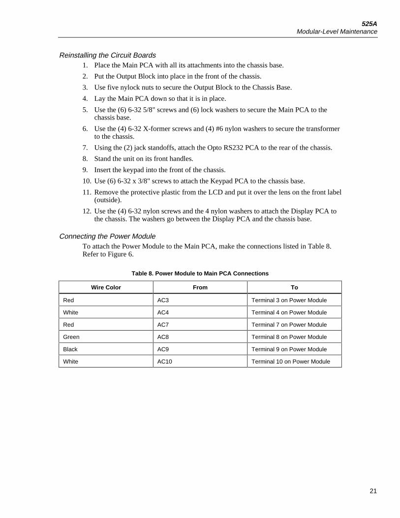
Connecting the Power ModuleTo attach the Power Module to the Main PCA, make the connections listed in Table 8.Refer to Figure 6.
Table 8. Power Module to Main PCA Connections
Wire Color From To
Red AC3 Terminal 3 on Power Module
White AC4 Terminal 4 on Power Module
Red AC7 Terminal 7 on Power Module
Green AC8 Terminal 8 on Power Module
Black AC9 Terminal 9 on Power Module
White AC10 Terminal 10 on Power Module
525AService Manual
22
Green wire
Top view
Red wires
Green wire
Red wires
aby05f.eps
Figure 6. Power Module Connections
Final Assembly and InspectionTo complete final assembly and inspection, use a digital multimeter and verify thecontinuity of the connections listed in Table 9.
Table 9. Power Connections
Wire Color Position B Position on Main PCA
Red Power Module Pin 3 AC3
White Power Module Pin 4 AC4
Red Power Module Pin 7 AC7
Green Power Module Pin 8 AC8
Black Power Module Pin 9 AC9
White Power Module Pin 10 AC10
Red J5 LCD J2 A
Black J7 LCD J2 K
White J62 Opto Pin 4
N/A J52 Inside Chassis Base (no connection)
Install tie wraps around the AC wires, the Output Block wires, the LCD backlight wires,the 5-conductor cable, and the Opto-RS232 wires.

525APerformance Tests
23
Performance TestsThe following performance tests are used to verify the functionality of the Calibrator. Ifthe Calibrator fails any part of the performance tests, calibration adjustment or repair by aFluke Service Center is in order. For a list of service centers, refer to "Contacting Fluke"earlier in this manual.
Required Equipment ListTo complete the performance tests and calibration adjustment, the equipment listed inTable 10 is necessary. If the equipment listed is not available, equipment with the sameor better specifications can be substituted.
Table 10. Required Equipment
Manufacturer Model Equipment Purpose
Fluke Fluke- 525A/Leads Test Lead Set All Functions
Fluke 742A-10 ResistanceStandard, 10 Ω
100 mA source calibration
Fluke 742A-100 ResistanceStandard, 100 Ω
Low Ohms Measure and SPRTCalibration.
Fluke 742A-10K ResistanceStandard, 10K Ω
Hi Ohms Measure Calibration
Fluke 5520A Calibrator Low Ohms Measure and SPRTCalibration. Hi Ohms MeasureCalibration.
Wavetek 1281 DMM All functions except CJC
_ _ Ohms ShortingBlock
Low Ohms Measure and SPRTCalibration. Hi Ohms MeasureCalibration.
_ _ RTD Probe TC CJC Calibration
Hart Scientific 1521 PrecisionThermometer
TC CJC Calibration
Omega J ThermocoupleProbe
TC CJC Calibration
_ _ Lag Bath TC CJC Calibration
_ _Dewar Flask withlid
TC tests
_ _Banana Jack toCopper TC Mini-Connector Cable
TC tests

525AService Manual
24
Testing DC VoltageThe DC voltage amplitude accuracy test verifies the accuracy of DC voltage at the 525Acalibrator front panel Volts Source output. See Table 11.
Table 11. Testing DC Voltage
RangeNominalValue (V)
MeasuredValue Deviation %
90 Day Spec.(V)
One YearSpec. (V)
0 0.000003 0.000003
0.025 3.63E-06 3.75E-06
0.075 4.88E-06 5.25E-06
100 mV
0.1 5.5E-06 0.000006
0 0.00002 0.00002
0.25 2.63E-05 2.75E-05
0.75 3.88E-05 4.25E-05
1.0 V
1 0.000045 0.00005
0 0.0002 0.0002
2.5 0.000263 0.000275
7.5 0.000388 0.000425
10.0 V
10 0.00045 0.0005
0 0.002 0.002
25 0.002625 0.00275
75 0.003875 0.00425
100.0 V
100 0.0045 0.005

525APerformance Tests
25
Testing DC CurrentUse the Wavetek 1281 and the precision shunt to measure the 525A output as shown inFigure 7. Take the Voltage reading from the Wavetek 1281 and divide it by the 742A-1actual value. See Table 12.
525A
1281 DCV Function
Current Shunt
mAOutput
Terminals
INPUT
OUTPUT
HI
VOLTS mA RTD
HI
LO
HI
LO
LOTC
SENSE
INPUT/OUTPUT
4W RTD
SET RECALL
LOCAL EXP
AUTOSET
INPUTOUTPUT ZERO
RNG LOCK
C / FCJCSETUP
20V PK MAX
100V MAX
100mA MAX
20V PK MAX
20V PK MAX
525A TEMPERATURE / PRESSURE CALIBRATOR
0 •
1 2 3
4 5 6
7 8 9
/
VOLTSmA
TYPEUNITS
TCRTD
SHIFT
ENTER
STBYOPR
CE
ajr25f.eps
Figure 7. Measuring DC Current
Table 12. Measuring DC Current
100 mAOutput (A) Volt
Current(I=E/R)
742A-1ShuntValue 90 Day (A) 1 Year (A)
0.000 Direct Into1281 Input
0.000002 0.000002
0.025 0.0000041 0.0000045
0.075 0.0000083 0.0000095
0.100 0.0000105 0.000012

525AService Manual
26
Testing Thermocouple OutputFor this test the TC mV specifications will be used. When this test is combined with theCJC test, all functions of the TC output will have been checked. Typically, the cableneeds to connect the 525A to the 1281 and will need to be fabricated. The TC mini-connector will need to be copper - copper (white). Using copper wire, connect the TCmini-connector to standard banana jacks. See Figure 8 for a connection diagram.
For this test, the CJC (cold junction compensation) must be turned off. Press I 5 toturn off the CJC. XCJC on the display indicates that the CJC is turned off. Select TC, andOutput. Press Euntil mV/°C is shown on the display. Output the mV values listed inTable 13.
525A
1281
INPUT
OUTPUT
HI
VOLTS mA RTD
HI
LO
HI
LO
LOTC
SENSE
INPUT/OUTPUT
4W RTD
SET RECALL
LOCAL EXP
AUTOSET
INPUTOUTPUT ZERO
RNG LOCK
C / FCJCSETUP
20V PK MAX
100V MAX
100mA MAX
20V PK MAX
20V PK MAX
525A TEMPERATURE / PRESSURE CALIBRATOR
0 •
1 2 3
4 5 6
7 8 9
/
VOLTSmA
TYPEUNITS
TCRTD
SHIFT
ENTER
STBYOPR
CE
ajr26f.eps
Figure 8. Testing TC Output
Table 13. TC Temperatures
Nominal Voltage (mV) 90 Day Spec. (mV) 1 Year Spec. (mV)
-5.000 0.003125 0.00315
15.00 0.003375 0.00345
30.00 0.00375 0.0039
50.00 0.00425 0.0045
70.00 0.00475 0.0051

525APerformance Tests
27
Testing CJC (Cold Junction Compensation)Connect a Type-J thermocouple to the TC terminal on the 525A. Immerse thethermocouple and a precision thermometer into a mineral oil lag bath. The test set-up isshown in Figure 9.
Verify that the readings of the 525A and the precision thermometer are within the Type-Jspecifications:
• The 90 day spec is 0.14 °C
• The 1 year spec is 0.16 °C
Note Typical Type-J thermocouples Do not have specifications accurate enoughto be used as a standard. To maintain a good Test Uncertainty Ratio (TUR)a characterized Type-J thermocouple may need to be used.
CJC (Cold Junction Compensation) CalibrationConnect a Type-J thermocouple to the TC terminals on the Calibrator, and immerse thethermocouple and a precision thermometer in a mineral oil lag bath. The test setup isshown in Figure 9. Verify that the readings of the thermometer and the Calibrator arewithin the thermocouple specifications listed in the Specifications section.
525A
Dewar Flaskand Cap
Mineral OilLag Bath
J typeThermocouple
MercuryThermometer
INPUT
OUTPUT
HI
VOLTS mA RTD
HI
LO
HI
LO
LOTC
SENSE
INPUT/OUTPUT
4W RTD
SET RECALL
LOCAL EXP
AUTOSET
INPUTOUTPUT ZERO
RNG LOCK
C / FCJCSETUP
20V PK MAX
100V MAX
100mA MAX
20V PK MAX
20V PK MAX
525A TEMPERATURE / PRESSURE CALIBRATOR
0 •
1 2 3
4 5 6
7 8 9
/
VOLTSmA
TYPEUNITS
TCRTD
SHIFT
ENTER
STBYOPR
CE
ajr22f.eps
Figure 9. Connections for CJC Calibration

525AService Manual
28
Testing Thermocouple InputSet the 525A to TC input by pressing I then 7. All other 525A conditions will bethe same as the thermocouple output test, CJC off, mV/°C mode.
Connect the 525A to the 5520A as shown in Figure 10. Set the 5520A to output the mVvalues in Table 13.
525A
5520A Normal Output
DC VoltsFunction
INPUT
OUTPUT
HI
VOLTS mA RTD
HI
LO
HI
LO
LOTC
SENSE
INPUT/OUTPUT
4W RTD
SET RECALL
LOCAL EXP
AUTOSET
INPUTOUTPUT ZERO
RNG LOCK
C / FCJCSETUP
20V PK MAX
100V MAX
100mA MAX
20V PK MAX
20V PK MAX
525A TEMPERATURE / PRESSURE CALIBRATOR
0 •
1 2 3
4 5 6
7 8 9
/
VOLTSmA
TYPEUNITS
TCRTD
SHIFT
ENTER
STBYOPR
CE
ajr24f.eps
Figure 10. Connections for Measuring TC Input
525APerformance Tests
29
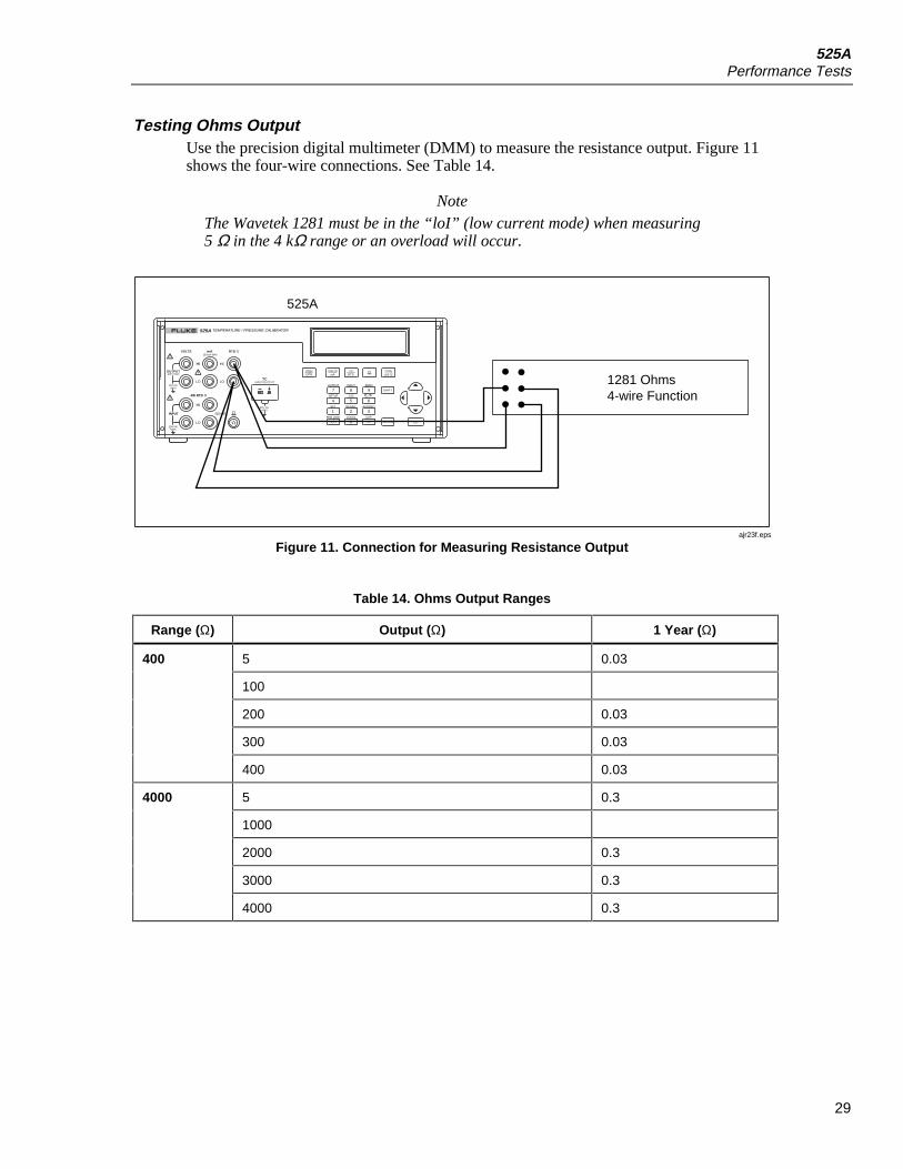
Testing Ohms OutputUse the precision digital multimeter (DMM) to measure the resistance output. Figure 11shows the four-wire connections. See Table 14.
NoteThe Wavetek 1281 must be in the “loI” (low current mode) when measuring5 Ω in the 4 kΩ range or an overload will occur.
525A
1281 Ohms4-wire Function
INPUT
OUTPUT
HI
VOLTS mA RTD
HI
LO
HI
LO
LOTC
SENSE
INPUT/OUTPUT
4W RTD
SET RECALL
LOCAL EXP
AUTOSET
INPUTOUTPUT ZERO
RNG LOCK
C / FCJCSETUP
20V PK MAX
100V MAX
100mA MAX
20V PK MAX
20V PK MAX
525A TEMPERATURE / PRESSURE CALIBRATOR
0 •
1 2 3
4 5 6
7 8 9
/
VOLTSmA
TYPEUNITS
TCRTD
SHIFT
ENTER
STBYOPR
CE
ajr23f.eps
Figure 11. Connection for Measuring Resistance Output
Table 14. Ohms Output Ranges
Range (Ω) Output (Ω) 1 Year (Ω)
5 0.03
100
200 0.03
300 0.03
400
400 0.03
5 0.3
1000
2000 0.3
3000 0.3
4000
4000 0.3

525AService Manual
30
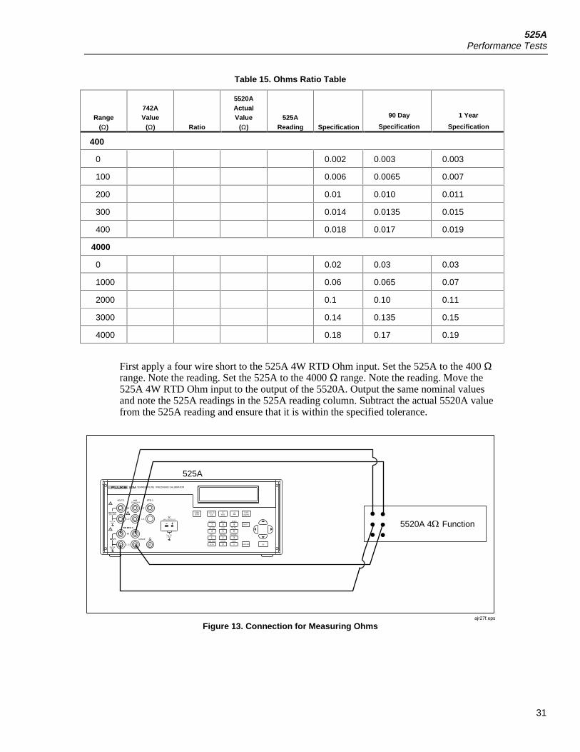
Testing Ohms InputBefore measuring ohms input, the ohms output of a 5520A must be “characterized”. Toachieve the needed accuracy, the Wavetek 1281 is used as a transfer standard and the742A is used as the reference standard. To find the true value of the 5520A output, theratio-input function of the Wavetek 1281 is used. The ratio function of the 1281 is locatedon the rear panel and is designated as Channel A and Channel B. Connect Channel A tothe 742A and connect the 5520A to Channel B, both using four-wire measure.See Figure 12 for a connection diagram.
1281
31 28 23 21 31 28 23 21
5520A
Rear inputs
742
Hi I I Lo+ - Hi I I Lo+ -
Chan A
Pin Pin
Chan B
ajr28f.eps
Figure 12. 1281 Connection Diagram
For the 400 Ω range use the 742A-1K and for the 4 kΩ range use the 742A-10K. Formore information on the correct usage of ratio mode refer to the 1281 Operators Manual.Use Table 15 to note the ratio indication on the 1281. Ignore the 0 Ω value. Use theformula (742A actual value/ratio indication * 100 = actual 5520A value) and enter thatohm value into the 5520A actual value column.
525APerformance Tests
31
Table 15. Ohms Ratio Table
Range(Ω)
742AValue
(Ω) Ratio
5520AActualValue
(Ω)525A
Reading Specification
90 Day
Specification
1 Year
Specification
400
0 0.002 0.003 0.003
100 0.006 0.0065 0.007
200 0.01 0.010 0.011
300 0.014 0.0135 0.015
400 0.018 0.017 0.019
4000
0 0.02 0.03 0.03
1000 0.06 0.065 0.07
2000 0.1 0.10 0.11
3000 0.14 0.135 0.15
4000 0.18 0.17 0.19
First apply a four wire short to the 525A 4W RTD Ohm input. Set the 525A to the 400 Ωrange. Note the reading. Set the 525A to the 4000 Ω range. Note the reading. Move the525A 4W RTD Ohm input to the output of the 5520A. Output the same nominal valuesand note the 525A readings in the 525A reading column. Subtract the actual 5520A valuefrom the 525A reading and ensure that it is within the specified tolerance.
5520A 4 Function
525A
INPUT
OUTPUT
HI
VOLTS mA RTD
HI
LO
HI
LO
LOTC
SENSE
INPUT/OUTPUT
4W RTD
SET RECALL
LOCAL EXP
AUTOSET
INPUTOUTPUT ZERO
RNG LOCK
C / FCJCSETUP
20V PK MAX
100V MAX
100mA MAX
20V PK MAX
20V PK MAX
525A TEMPERATURE / PRESSURE CALIBRATOR
0 •
1 2 3
4 5 6
7 8 9
/
VOLTSmA
TYPEUNITS
TCRTD
SHIFT
ENTER
STBYOPR
CE
ajr27f.eps
Figure 13. Connection for Measuring Ohms

525AService Manual
32
Testing Pressure ModulesThe Fluke 700 series pressure modules are calibrated separately from the 525A. Thecalibration follows the pressure module, so only a performance test is needed. Connectany of the Fluke 700 series pressure modules to the pressure module connector. Verifythat the Calibrator reads pressure.
Calibration AdjustmentAdjusting the Calibrator requires no mechanical adjustment. All adjustments areperformed electronically. The calibration is performed via serial communications port.The adjustments take place over the normal RS232 interface. Refer to Table 6 for a list ofrequired equipment for performing the following procedures. Note that the adjustment forthe Resistance Measure was designed to be especially flexible, allowing for the use offixed resistors.
Initiating CommunicationTerminals can be set up using terminal communications software on a personal computer(PC). Connect a 9-pin null modem cable to the RS232 connector on the back of theCalibrator. Connect the other end of the cable to the PC/PC serial port. An adapter maybe needed for terminals that use 25 pin D serial connectors. A terminal program such asWindow HyperTerminal may be used in the PC.
The terminal settings need to be set as follows:
Bits per second: 9600
Data bits: 8
Parity: None
Stop bits: 1
Flow control: None
Local echo: on
Starting Adjustment ModeThe Calibrator needs to warm up for at least 30 minutes before performing theseprocedures. This will allow any thermal changes in the Calibrator to stabilize. If the unithas been repaired or is new, it should be given 24 hours to burn in. To initiate thecalibration mode, use the PC to send the CAL_START command. The following will bedisplayed on the PC:
Calibration is password protected
Enter Password:
525ACalibration Adjustment
33
The password is 525. Enter the password through the PC keyboard and the following isdisplayed on the PC monitor:
Calibration Menu:
1: 100 mV Source
2: 1 V Source
3: 10 V Source
4: 100 V Source
5: 100 mA Source
6: Hi Ohms Source
7: Low Ohms Source
8: Hi Ohms Measure
9: Low Ohms Measure
10: SPRT 25
11: TC SOURCE
12: TC READ
13: TC CJC
14: Calibrate DAC
Enter Selection:
Adjustment SequenceManual calibration of the Calibrator is a menu driven process. The menu consists of 14different menu selections for calibration of the different operating modes.
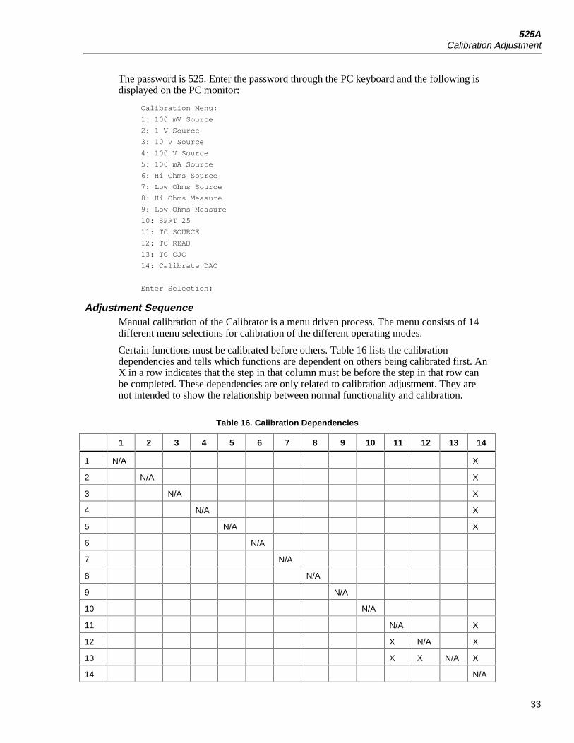
Certain functions must be calibrated before others. Table 16 lists the calibrationdependencies and tells which functions are dependent on others being calibrated first. AnX in a row indicates that the step in that column must be before the step in that row canbe completed. These dependencies are only related to calibration adjustment. They arenot intended to show the relationship between normal functionality and calibration.
Table 16. Calibration Dependencies
1 2 3 4 5 6 7 8 9 10 11 12 13 14
1 N/A X
2 N/A X
3 N/A X
4 N/A X
5 N/A X
6 N/A
7 N/A
8 N/A
9 N/A
10 N/A
11 N/A X
12 X N/A X
13 X X N/A X
14 N/A
525AService Manual
34
14: Calibrate DAC, Digital to Analog Converter AdjustmentIf all of the functions that are affected by the digital to analog converter (DAC)adjustment are going to be adjusted, start with step 14 which adjusts the DAC. Do notadjust the DAC unless all of the ranges affected are going to be readjusted. Duringnormal calibration adjustment, it is necessary to adjust the DAC. However, for example,if a mistake were made in the 100 V range, the user would not want to readjust the DAC.If it were readjusted, the user would have to readjust everything that depends on thatrange.
To adjust the calibration of the DAC from the menu, type 14 and then press the Enter keyon the PC keyboard. No external connection is necessary. The DAC adjust will execute,save the calibration constants, then display the Calibration Menu on the PC.
1: 100 mV Source to 4: 100 V Source, Adjusting DC SourceAdjusting the voltage output breaks down into four distinct ranges; each can be adjustedseparately using menu selections 1-4. The adjustments are done in 2 parts. The first partsets the 0 and span values. The second part is to fine adjust the zero, span, and adjusts thelinearity. The example below is for the 1 V range. The other ranges use the same stepswith different voltage values. Refer to Table 17 for a list of equipment used in thissection.
Table 17. List of Equipment for Voltage Calibration Adjustments
Manufacturer Model Equipment
Fluke FLUKE-525A/LEADS Test Lead Set
Wavetek 1281 DMM
1. Connect the calibrator VOLTS HI and LO to the DMM input.
2. Set the DMM to DC Volts.
3. Type 2 and push the Enter key on the PC. The following is displayed on the PC:
First Calibration Point. Enter the Volts displayed:
4. When the reading on the DMM stabilizes, type the reading value on the PC and pressEnter. After the value has been entered, the following is displayed on the PC:
Second Calibration Point. Enter the Volts displayed:
5. When the reading on the DMM stabilizes, type the reading value on the PC and pressEnter. After the value has been entered, the following is displayed on the PC:
Second Calibration Point. Enter the Volts displayed:
Adjust the 0 Percent of Scale, 8 for up 2 for down, Press Enter When Stable
The second part of the calibration adjustment follows. In the 10 key section of the PCkeyboard, use the 8 (up arrow) to increase the output voltage displayed or 2 (down arrow)to decrease the output voltage displayed. Keep in mind the lag time between a change inoutput voltage to a stable display on the DMM. Make small changes then wait for a stablereading. Adjust the output so that you get a good, stable 0 V reading. When satisfied withthe reading, press the Enter key.

525ACalibration Adjustment
35
The PC display shows:
Please Wait…
25755
Adjust to 25 Percent of Scale, 8 for up 2 for down, Press Enter When Stable
The value is the raw A/D counts for this calibration point, followed by a prompt to adjustthe 25 % of scale value. Use the 8 (up) and 2 (down) key on the PC to adjust the output toget a reading very close to 25 % of the range full scale.
• For the 100 mV range, 25 % is 25 mV
• For the 1 V range, 25 % is 250 mV
• For the 10 V range, 25 % is 2.5 V
• For the 100 V range, 25 % is 25 V
When satisfied with the reading, press Enter and the PC shows:
Please Wait…
2083980
Adjust to 50 Percent of Scale, 8 for up 2 for down, Press Enter When Stable
The value is the raw A/D counts for this calibration point followed by a prompt to adjustthe 50 % of scale value. Use the 8 (up) and 2 (down) key on the PC to adjust the output toget a reading very close to 50 % of the range full scale.
• For the 100 mV range, 50 % is 50 mV
• For the 1 V range, 50 % is 500 mV
• For the 10 V range, 50 % is 5.0 V
• For the 100 V range, 50 % is 50 V
This process continues until the user goes through the 100 % range. Use the sameprocedures for those ranges.
After the raw A/D counts are displayed, this calibration step is complete. The calibrationconstants for the range have been saved. Press Enter to return to the Calibration menu.
5: 100 mA Source, Adjusting DC Current SourceAdjusting the DC current output is similar to the voltage source calibration adjustment.Just like the voltage calibration adjustment, this adjustment is executed in 2 parts. Part 1sets the 0 and span values. Part 2 is to fine adjust the zero, span, and adjusts the linearity.Refer to Table 18 for a list of equipment used in this section.
Table 18. List of Equipment for Current Calibration Adjustments
Manufacturer Model Equipment
Fluke FLUKE-525A/LEADS Test Lead Set
Fluke 742A-10 Resistance Standard, 10 Ω
Wavetek 1281 DMM

525AService Manual
36
The voltage is measured across a 10 Ω shunt resistor instead of measuring currentdirectly.
Readings taken from the DMM need to be converted to mA (multiplied by 100) beforethey can be entered in at the PC.
1. Set the DMM to read DC Volts.
2. Use the test leads for the following connections:
a. Connect the mA HI jack of the Calibrator to the high side of the current input ofthe 742A.
b. Connect the mA LO jack of the calibrator to the low side of the current input ofthe 742A.
c. Connect the high side of the sense output of the 742A to the high side of thevoltage input of the DMM.
d. Connect the low side of the sense output of the 742A to the low side of thevoltage into the DMM.
3. Type 5 and then press the Enter key on the PC. The following will be displayed onthe PC:
First Calibration Point. Enter the mAmps displayed:
4. When the reading on the DMM stabilizes, calculate the mA (multiply the voltagereading by 100) and type the mA on the PC then press the Enter key. After the valuehas been entered, the following shows on the PC:
Second Calibration Point. Enter the mAmps displayed:
5. When the reading on the DMM stabilizes, calculate the mA (multiply the voltagereading by 100) and type the mA on the PC then press the Enter key. After the valuehas been entered, the following shows on the PC:
Second Calibration Point. Enter the volts displayed
Adjust the 0 Percent of Scale, 8 for up 2 for down, Press Enter When Stable
The second part of the calibration adjustment follows. In the 10 key section of the PCkeyboard, use the 8 (up arrow) to increase the output voltage displayed or 2 (down arrow)to decrease the output voltage displayed. Keep in mind the lag time between a change inoutput voltage to a stable display on the DMM. Make small changes then wait for a stablereading. Adjust the output so that you get a good, stable 0 V reading. When satisfied withthe reading, press the Enter key.
The PC display shows:
Please Wait…
111260
Adjust to 25 Percent of Scale, 8 for up 2 for down, Press Enter When Stable
The value is the raw A/D counts for this calibration point, followed by a prompt to adjustthe 25 % of scale value. Use the 8 (up) and 2 (down) key on the PC to adjust the output toget a reading very close to 25 % of the range full scale.
• For the 100 mA range, 25 % is 250 mV
When satisfied with the reading, press Enter and the PC shows:

525ACalibration Adjustment
37
Please Wait…
2147203
Adjust to 50 Percent of Scale, 8 for up 2 for down, Press Enter When Stable
The value is the raw A/D counts for this calibration point followed by a prompt to adjustthe 50 % of scale value. Use the 8 (up) and 2 (down) key on the PC to adjust the output toget a reading very close to 50 % of the range full scale.
• For the 100 mA range, 50 % is 500 mV
Repeat this process until the user goes through the 100 % range. Use the same proceduresfor those ranges.
• For the 100 mA range, 75 % is 750 mV
• For the 100 mA range, 100 % is 1 V
After the raw A/D counts are displayed, this calibration step is complete. The calibrationconstants for the range have been saved. Press Enter to return to the Calibration menu.
6: Hi Ohms Source, Adjusting High Resistance SourceWhen calibrating the 5-4000 Ω output range (High Ohms Source), the calibrator outputstwo calibration points. After the output becomes stable, the values are entered at the PC.
1. Use the same test equipment listed in Table 16.
2. Make the following connections:
a. Connect the HI RTD Ω jack of the Calibrator to the high side of the Ohmsmeasure sense jacks on the DMM.
b. Connect the LO RTD Ω jack of the Calibrator to the low side of the Ohmsmeasure sense jacks on the DMM.
c. Connect the HI RTD Ω jack of the Calibrator to the high side of the Ohmsmeasure current source jacks on the DMM.
d. Connect the LO RTD Ω jack of the Calibrator to the low side of the Ohmsmeasure current source jacks on the DMM. It is important that the sense leads beon the bottom of the stack on the Calibrator Ohms source jacks.
3. Set the DMM to measure 4-wire ohms.
4. Type 6, then the Enter key on the PC. The PC will display:
First Calibration Point. Enter the Ohms displayed:
5. When the reading displayed on the DMM stabilizes, type the reading value on the PCand press the Enter key. After the value has been entered, the PC displays thefollowing:
Second Calibration Point. Enter the Ohms displayed:
6. When the reading displayed on the DMM stabilizes, type the reading value on the PCand press the Enter key. After the second value has been entered, the Calibrator willreturn to the calibration menu.

525AService Manual
38
7: Low Ohms, Adjusting Low Ohms SourceWhen calibrating the 5-400 Ω output range (High Ohms Source), the calibrator outputstwo calibration points. After the output becomes stable, the values are entered at the PC.
1. Use the same test equipment listed in Table 16.
2. Use the same connections as in 6: Adjusting High Resistance Source.
3. Set the DMM to measure 4-wire ohms.
4. Type 7, then press the Enter key on the PC. The PC will display:
First Calibration Point. Enter the Ohms displayed:
5. When the reading displayed on the DMM stabilizes, type the reading value on the PCand press the Enter key. After the value has been entered, the PC displays thefollowing:
Second Calibration Point. Enter the Ohms displayed:
6. When the reading displayed on the DMM stabilizes, type the reading value on the PCand press the Enter key. After the second value has been entered, the Calibrator willreturn to the calibration menu.
8: Hi Ohms, Adjusting High Resistance MeasureWhen adjusting the calibration for the 5-4000 Ohms Measure range (High OhmsMeasure), the Calibrator will first measure a short and then two resistances. Refer toTable 19 for a list of equipment used in this section.
Table 19. List of Equipment for High Ohms Measure Calibration Adjustments
Manufacturer Model Equipment
Fluke FLUKE-525A/LEADS Test Lead Set
Fluke 742A-10K Resistance Standard, 10K Ω
Fluke 5520A Calibrator
Wavetek 1281 DMM
1. Insert a 4-wire short into the 525A 4W RTD Ω jacks.
2. Type 8 then press the Enter key on the PC. The following will show on the PC:
Input 0 Ohms, Press Enter When Stable
3. Allow a few seconds for stabilization, then press the Enter key. In a few moments thefollowing appears on the PC:
Input ~2000 Ohms, Enter the actual value when stable:
The ~2000 indicates that the desired resistance is about 2000 Ω. The actual resistance isnot as important as the accuracy with which the value is known. The method describedbelow uses the 1281 to establish a ratio between the 5520A output and the 742 toimprove the accuracy with which the 5520A’s output resistance is known.
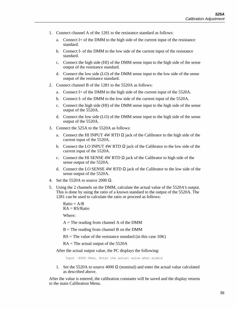
525ACalibration Adjustment
39
1. Connect channel A of the 1281 to the resistance standard as follows:
a. Connect I+ of the DMM to the high side of the current input of the resistancestandard.
b. Connect I- of the DMM to the low side of the current input of the resistancestandard.
c. Connect the high side (HI) of the DMM sense input to the high side of the senseoutput of the resistance standard.
d. Connect the low side (LO) of the DMM sense input to the low side of the senseoutput of the resistance standard.
2. Connect channel B of the 1281 to the 5520A as follows:
a. Connect I+ of the DMM to the high side of the current input of the 5520A.
b. Connect I- of the DMM to the low side of the current input of the 5520A.
c. Connect the high side (HI) of the DMM sense input to the high side of the senseoutput of the 5520A.
d. Connect the low side (LO) of the DMM sense input to the high side of the senseoutput of the 5520A.
3. Connect the 525A to the 5520A as follows:
a. Connect the HI INPUT 4W RTD Ω jack of the Calibrator to the high side of thecurrent input of the 5520A.
b. Connect the LO INPUT 4W RTD Ω jack of the Calibrator to the low side of thecurrent input of the 5520A.
c. Connect the HI SENSE 4W RTD Ω jack of the Calibrator to high side of thesense output of the 5520A.
d. Connect the LO SENSE 4W RTD Ω jack of the Calibrator to the low side of thesense output of the 5520A.
4. Set the 5520A to source 2000 Ω.
5. Using the 2 channels on the DMM, calculate the actual value of the 5520A’s output.This is done by using the ratio of a known standard to the output of the 5520A. The1281 can be used to calculate the ratio or proceed as follows:
Ratio = A/BRA = RS/Ratio
Where:
A = The reading from channel A of the DMM
B = The reading from channel B on the DMM
RS = The value of the resistance standard (in this case 10K)
RA = The actual output of the 5520A
After the actual output value, the PC displays the following:
Input ~4000 Ohms, Enter the actual value when stable
1. Set the 5520A to source 4000 Ω (nominal) and enter the actual value calculatedas described above.
After the value is entered, the calibration constants will be saved and the display returnsto the main Calibration Menu.

525AService Manual
40
9: Low Ohms, Adjusting Low Resistance MeasureWhen adjusting the calibration for the 5-400 Ohms Measure range (Low Ohms Measure),the Calibrator will measure 3 resistances. Refer to Table 20 for a list of equipment usedin this section.
Table 20. List of Equipment for High Ohms Measure Calibration Adjustments
Manufacturer Model Equipment
Fluke FLUKE-525A/LEADS Test Lead Set
Fluke 742A-100 Resistance Standard, 100 Ω
Fluke 5520A Calibrator
Wavetek 1281 DMM
The method described below uses the 1281 to establish a ratio between the 5520A outputand the 742 to improve the accuracy with which the 5520A’s output resistance is known.
1. Connect channel A of the 1281 to the Resistance Standard as follows:
a. Connect I+ of the DMM to the high side of the current input of the ResistanceStandard.
b. Connect I- of the DMM to the low side of the current input of the ResistanceStandard.
c. Connect the high side (HI) of the DMM sense input to the high side of the senseoutput of the resistance standard.
d. Connect the low side (LO) of the DMM sense input to the low side of the senseoutput of the resistance standard.
2. Connect channel B of the 1281 to the 5520A as follows:
a. Connect I+ of the DMM to the high side of the current input of the 5520A.
b. Connect I- of the DMM to the low side of the current input of the 5520A.
c. Connect the high side (HI) of the DMM sense input to the high side of the senseoutput of the 5520A.
d. Connect the low side (LO) of the DMM sense input to the low side of the senseoutput of the 5520A.
3. Connect 525A to the 5520A as follows:
a. Connect HI INPUT 4W RTD Ω jack of the 525A to the high side of the currentinput of the 5520A.
b. Connect LO INPUT 4W RTD Ω jack of the 525A to the low side of the currentinput of the 5520A.
c. Connect the HI SENSE 4W RTD Ω jack of the 525A to the high side of the senseoutput of the 5520A.
d. Connect the LO SENSE 4W RTD Ω jack of the 525A sense input to the low sideof the sense output of the 5520A.
4. Type 9 enter on the PC. The following will be displayed on the PC.
Input ~100 Ohms, Enter the actual value when stable:

525ACalibration Adjustment
41
The ~100 indicates that the desired resistance is about 100 Ω. The actual resistanceis not as important as the accuracy with which the value is known.
5. Set the 5520A to source 100 Ω.
6. Using the two channels on the DMM, calculate the actual value of the 5520A’soutput. This is done by using the ratio of a known standard to the output of the5520A. You can use the 1281 to calculate the ratio or proceed as follows.
Ratio = A/B
RA = RS/Ratio
Where:
A = The reading taken from channel A on the DMM.
B = The reading taken from channel B on the DMM.
RS = The value of the resistance standard (in this case 100 Ω).
RA = The actual output of the 5520A.
After the actual output value is entered, the PC displays the following:
Input ~200 Ohms, Enter the actual value when stable:
7. Set the 5520A to source 200 Ω (nominal) and enter the actual value calculated asdescribed above.
Set Input ~400 Ohms, Enter the actual value when stable:
8. Set the 5520A to source 400 Ω (nominal) and enter the actual value calculated asdescribed above.
After the value is entered, the calibration constants will be saved and the display willreturn to the main Calibration Menu.
10: SPRT 25, Adjusting SPRT Low Resistance MeasureThe SPRT 25 range is used for measuring SPRTs (typically 25 Ohm R0) and Ohms from0 to 100 Ohms in the 0-400 Ohms range. The 525A will measure a short, and 2resistances. Refer to Table 21 for a list of equipment used in this section.
Table 21. List of Equipment for Low Ohms Measure Calibration Adjustments
Manufacturer Model Equipment
Fluke FLUKE-525A/LEADS Test lead set
Fluke 742A-100 Resistance Standard, 100 Ω
Fluke 5520A Calibrator
Wavetek 1281 DMM
1. Insert a good 4-wire short into the 525A 4W RTD Ω jacks.
2. Type 10 and press the Enter key on the PC. The following is displayed on the PC.
Input 0 Ohms, Press Enter When Stable
525AService Manual
42
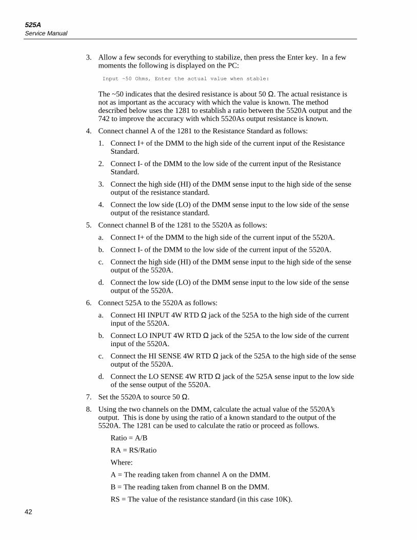
3. Allow a few seconds for everything to stabilize, then press the Enter key. In a fewmoments the following is displayed on the PC:
Input ~50 Ohms, Enter the actual value when stable:
The ~50 indicates that the desired resistance is about 50 Ω. The actual resistance isnot as important as the accuracy with which the value is known. The methoddescribed below uses the 1281 to establish a ratio between the 5520A output and the742 to improve the accuracy with which 5520As output resistance is known.
4. Connect channel A of the 1281 to the Resistance Standard as follows:
1. Connect I+ of the DMM to the high side of the current input of the ResistanceStandard.
2. Connect I- of the DMM to the low side of the current input of the ResistanceStandard.
3. Connect the high side (HI) of the DMM sense input to the high side of the senseoutput of the resistance standard.
4. Connect the low side (LO) of the DMM sense input to the low side of the senseoutput of the resistance standard.
5. Connect channel B of the 1281 to the 5520A as follows:
a. Connect I+ of the DMM to the high side of the current input of the 5520A.
b. Connect I- of the DMM to the low side of the current input of the 5520A.
c. Connect the high side (HI) of the DMM sense input to the high side of the senseoutput of the 5520A.
d. Connect the low side (LO) of the DMM sense input to the low side of the senseoutput of the 5520A.
6. Connect 525A to the 5520A as follows:
a. Connect HI INPUT 4W RTD Ω jack of the 525A to the high side of the currentinput of the 5520A.
b. Connect LO INPUT 4W RTD Ω jack of the 525A to the low side of the currentinput of the 5520A.
c. Connect the HI SENSE 4W RTD Ω jack of the 525A to the high side of the senseoutput of the 5520A.
d. Connect the LO SENSE 4W RTD Ω jack of the 525A sense input to the low sideof the sense output of the 5520A.
7. Set the 5520A to source 50 Ω.
8. Using the two channels on the DMM, calculate the actual value of the 5520A’soutput. This is done by using the ratio of a known standard to the output of the5520A. The 1281 can be used to calculate the ratio or proceed as follows.
Ratio = A/B
RA = RS/Ratio
Where:
A = The reading taken from channel A on the DMM.
B = The reading taken from channel B on the DMM.
RS = The value of the resistance standard (in this case 10K).

525ACalibration Adjustment
43
RA = The actual output of the 5520A.
9. After the actual output value is entered, the PC displays the following:
Input ~100 Ohms, Enter the actual value when stable:
10. Set the 5520A to source 100 Ω (nominal) and enter the actual value calculated asdescribed above.
After entering the value, the calibration constants will be saved and the display returns tothe main Calibration Menu.
11: TC SOURCE, Adjusting TC mVolt SourceThe adjust of the TC Source output range is similar to the first part of the voltage sourcecalibration, the 525A outputs two Adjust points, after the output becomes stable thevalues can be entered at the PC. Refer to Table 22 for a list of equipment used in thissection.
Table 22. List of Test Equipment for Adjusting TC Source
Manufacturer Model Equipment
Fluke FLUKE-525A/LEADS Test lead set
Wavetek 1281 DMM
1. Use a copper TC mini-plug cable with low thermal EMF jacks on the other end toconnect the Calibrator to the DMM. Make certain the polarity is correct. Set theDMM to read DC Volts.
2. Type 11 and press the Enter key on the PC. The following is displayed on the PC:
First Calibration Point. Enter the Volts displayed:
3. When the reading displayed on the DMM stabilizes, type the reading value on the PCand press the Enter key. After the value has been entered, the following is displayedon the PC.
Second Calibration Point. Enter the Volts displayed:
4. When the reading displayed on the DMM stabilizes, type the reading value on the PCand press the Enter key.
After the calibration constants are saved, the Calibration Menu is displayed on the PC.
12: TC Read, Adjusting TC mVolt MeasureThe adjust of the TC Source output range is similar to the first part of the voltage sourcecalibration, the Calibrator outputs 2 adjustment points, after the output stabilizes, thevalues can be entered from PC. Refer to Table 23 for a list of equipment used in thissection.
Table 23. List of Test Equipment for Adjusting TC Read
Manufacturer Model Equipment
Fluke FLUKE-525A/LEADS Test lead set
Wavetek 1281 DMM

525AService Manual
44
Use a copper TC mini-plug cable with low thermal EMF jacks on the other end toconnect the 525A to the DMM. Make certain the polarity is correct.
1. Set the DMM to read DC Volts.
2. Type 12 and press the Enter key on the PC. The following is displayed on the PC:
Adjust to -10 mV, 8 for up 2 for down, Press Enter When Stable
3. In the 10 key section of the PC keyboard, use the 8 (up arrow) to increase the outputvoltage displayed or 2 (down arrow) to decrease the output voltage displayed. Keepin mind the lag time between a change in output voltage to a stable display on theDMM and make small changes. Wait for the reading to stabilize.
4. Adjust the output so that there is a stable -10 mV reading. When satisfied with thereading, press the Enter key on the PC. The PC display will show:
Please Wait...
-1073806
Adjust to 15 mV, 8 for up 2 for down, Press Enter When Stable
5. The value is the raw A/D counts for this calibration point, followed by a prompt toadjust for 15 mV. Use the 8 (up) and 2 (down) key on the PC to adjust the output sothat a reading very close to 15 mV is obtained.
6. When satisfied with the reading, press the Enter key. The PC display shows:
Please Wait...
1610975
Adjust to 40 mV, 8 for up 2 for down, Press Enter When Stable
7. The value is the raw A/D counts for this calibration point, followed by a prompt toadjust for 40 mV. Use the 8 (up) and 2 (down) key on the PC to adjust the output sothat a reading very close to 40 mV is obtained.
8. When satisfied with the reading, press the Enter key. The PC display shows:
Please Wait...
4295762
Adjust to 65 mV, 8 for up 2 for down, Press Enter When Stable
9. The value is the raw A/D counts for this calibration point, followed by a prompt toadjust for 65 mV. Use the 8 (up) and 2 (down) key on the PC to adjust the output sothat a reading very close to 65 mV is obtained.
10. When satisfied with the reading, press enter. The PC display will show:
Please Wait...
6980475
Adjust to 75 mV, 8 for up 2 for down, Press Enter When Stable
11. The value is the raw A/D counts for this calibration point, followed by a prompt toadjust for 75 mV. Use the 8 (up) and 2 (down) key on the PC to adjust the output so

525ACustomer Replaceable Parts
45
that a reading very close to 75 mV is obtained. When satisfied with the reading,press the Enter key. The PC display will show:
Please Wait...
8054372
12. After the raw A/D counts are displayed, the calibration step is complete. Thecalibration constants for the range have been saved. Press the Enter key to return tothe Calibration Menu.
13: TC CJC, Adjusting TC Cold Junction TemperatureThe Calibration of the TC CJC (cold junction compensation) is a critical part of thecalibration adjustment process. It is important that the thermocouple junction be allowedto completely stabilize. Refer to Table 24 for a list of equipment used in this section.
Table 24. List of Test Equipment for Adjusting TC CJC
Manufacturer Model Equipment
Hart Scientific 1521 Precision Thermometer
Omega J Thermocouple Probe
_ _ Lag Bath
_ _ RTD Probe
The precision thermometer’s probe should already be in the lag bath along with the Jthermocouple probe.
1. Plug the mini-plug on the J thermocouple probe into the TC jack on the Calibrator.
2. Type 12 and press the Enter key on the PC. The following is displayed on the PC:
Input a Type J Thermocouple. Enter temperature when stable.
3. Allow about three minutes for all of the thermal junctions to stabilize.
4. Enter the temperature from the temperature reference. The final display should looklike the following.
Input a Type J Thermocouple. Enter temperature when stable. 377376 26.699269
1103.936911
1124.668121
0.000000
-20.731080
26.698029
5. Press the Enter key to return to the Calibration Menu.
Customer Replaceable PartsReplacement parts are shown in Figure 14. Table 25 provides a description and partnumber of each replacement part. Table 26 lists optional accessories.

525AService Manual
46
9
3
428
5
5
13
1417
263025
16
1
106
11
8
18
33
15
2
31
32
7
2027
23
24
29
22
12
19
21
ajr20f.eps
Figure 14. Exploded View of the 525A

525ACustomer Replaceable Parts
47
Table 25. Replacement Parts
Item #Part
Number Description Location Quantity
1 1601576 525A Front Panel Decal Front Of Top Chassis 1
2 1617918 Fuse Drawer Power Module 1
W3 1645311 Fuse, (1/4A), FB For 1x0 VAC Fuse Drawer 2
W4 1645327 Fuse, (1/8A), FB For 2x0 VAC Fuse Drawer 2
5 1601601 525A Output Block Front Plate 1
6 295105 Allen Head Screw Handles To Case 20
7 320093 Flathead Screw Top Cover 10
8 1601583 525A Chassis Base 1
9 1601590 525A Instrument Top Cover 1
10 886341 Chassis Handles Front/Rear Chassis 4
11 868786 Plastic Feet Bottom of Chassis 4
12 1601078 Programming Door Back of Chassis Base 1
13 886382 Red 5-Way Binding Post Output Block 5
14 886379 Black 5-Way Binding Post Output Block 5
15 859939 #8 Washer, Low Thermal Output Block 10
16 850334 8-32 Nut, Low Thermal Output Block 10
17 942714 Pressure Conn, Circ, 5 Socket Output Block 1
18 1601565 525A Keypad Front Of Top Chassis 1
20 1618591 Main PCA 1
20* 1642173 PEP Main PCA 1
22 1617941 Display PCA 1
23 1618617 Keypad PCA 1
24 1640190 6-32 X 3/8" Screw, Nylon, Pan, Display To Chassis 4
25 1640305 Nylock Nut 6-32 Block To Chassis 5
25 1640305 Nylock Nut 6-32 Power Module to Chassis 2
26 494641 5-20 X .312, Screw TC PCA To Output Block 2
27 110338 #6, Int Tooth Lock Washer Main PCA To Chassis 6
27 152181 6-32 X 5/8’’ Screw, Round Main PCA To Chassis 6
28 1640225 6-32 X 2-1/2" Screw, Ph Transformer To Chassis 4
29 1640202 #6 Nylon Washer Display PCA To Chassis 4
29 1640202 #6 Nylon Washer Transformer 4
30 1618600 TC PCA 1

525AService Manual
48
Table 25. Replacement Parts (continued)
Item #Part
Number Description Location Quantity
31 1617929 Power Module Back Of Chassis 1
32 1617907 Voltage Selector Power Module 1
33 1638939 Opto RS232 PCA Back of Chassis 1
Not shown 271973 .1uf/250V Cap., Polyester Output Block 1
Not shown 1617866 14 Cond Ribbon Cable J4 To Display 1
Not shown 1617882 5 Cond Ribbon Cable Lemo PCA To Main PCA 1
Not shown 1627364 12 Cond Ribbon Cable J11 To Keypad PCA 1
34 1640331 Pressure-Lemo PCB Lemo Connector 1
Not shown 172080 Cable Tie, 4’’ 4
Not shown 1618621 Line Cord, 3 COND 1
Not shown 110338 #6, Int Tooth Lock Washer Keypad PCA to Chassis 5
Not shown 152165 #6 X 3/8" Screw, PH Keypad PCA to Chassis 5
Not shown 152165 #6 X 3/8" Screw, PH Power Module to Chassis 2
Not shown 152165 #6 X 3/8" Screw, PH Program Door to Chassis 1
Not shown 721266 Lug, Closed, Round, #8 Stud Output Block 11
Not shown 110619 1/4"-28 Nut Ground Lug Stud 2
Not shown 448092 Jack Screw RS232 Conn 9 Pin D-Sub 1
Not shown 110338 1/4" Int Tooth Lock Washer Binding Post Stud 2
Not shown 102889 Binding Head Thumbscrew Binding Post Stud 1
Not shown 102707 Binding Post Jack Chassis Back 1
Not shown 1601541 525A Getting Started Guide 1
Not shown 1601552 525A User Manual (on CD) 1
W For safety, use exact replacement only.
* PEP is an exchange of a repairable assembly for a factory repaired one.
Table 26. Accessories
Description Part Number
Fluke 525A/LEAD, Lead wire set 1616018
Fluke Y525 Rack Mount Kit 1622027
RS43, RS232 Null Modem Cable 946470
525A Service Manual 1644492