Embed Size (px)
Citation preview

— ABB Limited Measurement & Analytics Howard Road, St. Neots Cambridgeshire, PE19 8EU UK Tel: +44 (0)870 600 6122 Fax: +44 (0)1480 213 339 Email: [email protected] ABB Automation Products GmbH Measurement & Analytics Schillerstr. 72 32425 Minden Germany Tel: +49 571 830-0 Fax: +49 571 830-1806 abb.com/temperature
ABB Inc. Measurement & Analytics 125 E. County Line Road Warminster, PA 18974 USA Tel: +1 215 674 6000 Fax: +1 215 674 7183
DS/
TSP3
X1-
EN R
ev. E
0
1.20
19
— We reserve the right to make technical changes or modify the contents of this document without prior notice. With regard to purchase orders, the agreed particulars shall prevail. ABB does not accept any responsibility whatsoever for potential errors or possible lack of information in this document. We reserve all rights in this document and in the subject matter and illustrations contained therein. Any reproduction, disclosure to third parties or utilization of its contents – in whole or in parts – is forbidden without prior written consent of ABB. © ABB 2019 3KXT161002R1001
— ABB MEASUREMENT & ANALYTICS | DATA SHEET
SensyTemp TSP311, TSP321, TSP331 Temperature sensors

2 SENSYTEMP TSP311, TSP321, TSP331 TEMPERATURE SENSORS | DS/TSP3X1-EN REV. E SENSYTEMP TSP311, TSP321, TSP331 TEMPERATURE SENSORS | DS/TSP3X1-EN REV. E 4
— Measurement made easy Sturdy and versatile
— Heavy-duty design
— Modular design • Measuring inset, thermowell, extension tube, connection
head, transmitter
— Extremely robust connection head • Aluminum or stainless steel screw-on cap for offshore
applications
— Transmitter in connection head • Optional LCD indicator • Optional display function (type AS) or display with
configuration function (type A) • SIL 2 for transmitter
— Approvals • SIL 2 for sensors with integrated transmitter • IECEx, ATEX, EAC Ex (GOST)
— Areas of application • Offshore and coastal areas, Petroleum and natural gas
production and transport, Petrochemical industry, Chemical industry, Energy industry

SensyTemp TSP311, TSP321, TSP331 | DS/TSP3X1-EN Rev. E 3
Overview of temperature sensors
Type TSP311 TSP321 TSP331
Legend:
K = Extension tube length
U = Installation length
N = Nominal length
L = Thermowell length
Design No thermowell, for installation in
existing thermowell
Welded protective fitting
manufactured from pipe material
Drilled thermowell manufactured
from bar stock material
Measuring inset, extension tube with thermowell interface, connection head, transmitter, optional LCD display
Process connection Insertion in an existing thermowell.
Functional reliability is only assured
with an additional thermowell!
Screw-in thread, flange,
compression fitting
Welded connections, screw-in
thread, flange
Transport temperature / Storage
temperature
-20 … 70 °C (-4 … 158 °F)
Maximum temperature limits (depending on the sensor and material selected, the lower temperature value in each case counts)
Sensor Thin film resistor: 400 °C (752 °F), wire wound resistor: 800 °C (1472 °F),
Thermocouples type K, N, J, E, L, S: 1600 °C (2912 °F)
Material
(other
materials
on request)
316L / 1.4404 ≤ 800 °C (1472 °F)
316Ti / 1.4571 ≤ 800 °C (1472 °F)
Inconel 600 / 2.4816 ≤ 1100 °C (2012 °F)
Hastelloy C276 / 2.4819 – ≤ 1100 °C (2012 °F) ≤ 1100 °C (2012 °F)
Monel 400 / 2.4360 – – 600 °C (1112°F)
1.7335 – – ≤ 540 °C (1004 °F)
1.7380 – – ≤ 570 °C (1058 °F)
1.5415 – – ≤ 500 °C (932 °F)
E-CTFE – ≤ 120 °C (248 °F) ≤ 120 °C (248 °F)
Tantalum – ≤ 250 °C (482 °F) ≤ 250 °C (482 °F)
Pressure Maximum 40 ... 100 bar
(580.15 bar ... 1450.38 psi)
Maximum 700 bar (10152.64 psi)
NOTICE The maximum temperatures and pressures specified are maximum values and do not take into consideration process-related stress. The effects of viscosity, medium velocity, pressure and temperature in the process usually cause these values to drop.
A10057
U
K
A10058
U
K
N
A10059
L
K

SensyTemp TSP311, TSP321, TSP331 Temperature sensors
4 DS/TSP3X1-EN Rev. E | SensyTemp TSP311, TSP321, TSP331
Overview of measuring insets TSA101
Industrial thermocouples and industrial resistance thermometers
Ceramic base with connection terminals Permanently-mounted transmitter Open connection wires
— Flexible and vibration-resistant ABB mineral insulated cable. The sheath for the resistance thermometer is manufactured from CrNi steel 1.4571
(316Ti) or nickel-base alloy 2.4816 (alloy 600) for thermocouples.
— Sensors in accordance with IEC 60751 platinum resistance thermometer with measuring ranges of -196 ... 800 °C (-320.8 ... 1472 °F) in three
tolerance classes or thermocouples in accordance with IEC 60584 and ANSI MC96.1 with measuring ranges of -40 ... 1200 °C (-40 ... 2192 °F),
each in two tolerance classes.
— Type S thermocouple in an accuracy class of 0 ... 1600 °C (32 ... 2912 °F).
— Fitted with single or double sensors.
— Optimum clamping at the measuring inset's holding plate is assured by generous spring travel (10 mm (0.39 inch)) on the part of the clamping
springs.
— Measuring insets are available with outer diameters of 3 mm (0.12 inch), 4.5 mm (0.24 inch), 6 mm (0.24 inch), and for thermocouples also 8 mm
(0.32 inch). 8 mm (0.32 inch) tip with sleeve and 10 mm (0.39 inch) tip with sleeve M = Measuring inset length Legend: TSP311: M = U + K + 40 mm TSP321: M = N + 40 mm TSP331: M = L + K + 40 mm K = Extension tube length U = Installation length N = Nominal length L = Thermowell length Change from one to two columns
M
������ A00054
M
������
M

SensyTemp TSP311, TSP321, TSP331 | DS/TSP3X1-EN Rev. E 5
Installation instructions
The usual way of ensuring that thermal measurements are accurate is to comply with the minimum installation length of the temperature sensor. Ideally, in the case of pipelines, the sensor on a thermometer should be located in the center of the pipe. If this is not possible, both in the case of pipes and with containers, a minimum installation length of 10 to 15-times the thermowell diameter is assumed to be sufficient.
A11141 Fig. 1
Insufficient nominal diameter In the case of pipelines with very small nominal diameters, insertion inside an elbow pipe is recommended. The thermowell tip is set in opposition to the flow direction of the medium. Inserting the thermowell with an adapter at an acute angle against the flow direction can also distort measurement results.
A11142 Fig. 2
Specifications
Resistance thermometer The use of a mineral insulated cable and special installed measuring elements ensure very high vibration resistance of all measuring insets of the TSP temperature sensors. The acceleration values of 30 m/sec2 (3 g), defined for already increased requirements in accordance with the standard IEC 60751, are exceeded by all measuring inset types for TSP temperature sensors. Apart from thin film resistors that reach their accuracy class within the temperature ranges defined by the standard IEC 60751, ABB also offers thin film resistors (TF) with extended temperature range. These TFs comply with the accuracy classes A and AA in a range of -196 ... 400 °C (-320.8 ... 752 °F) beyond the standard IEC 60751. These TFs are also available with increased resistance to vibration. The optimally suitable combination of measuring range, diameter, accuracy, and vibration resistance can be taken from the following tables. Designs Basic design Thin film resistor (TF) Measuring range Vibration resistance
Class B -50 ... 400 °C (-58 ... 752 °F) 100 m/sec2 (10 g)
at 10 to 500 Hz Class A -30 ... 300 °C (-22 ... 572 °F)
Class AA 0 ... 100 °C (32 ... 212 °F)
Class A
extended
-196 ... 400 °C (-321 ... 752 °F)
Class AA
extended
-196 ... 400 °C (-321 ... 752 °F)
Single sensor Double sensor
2-W 3-W 4-W 2-W 3-W 4-W
3.0 mm, class B
3.0 mm, class A
3.0 mm, class AA
4.5 mm, class B
4.5 mm, class A
4.5 mm, class AA
6.0 mm, class B
6.0 mm, class A
6.0 mm, class AA

SensyTemp TSP311, TSP321, TSP331 Temperature sensors
6 DS/TSP3X1-EN Rev. E | SensyTemp TSP311, TSP321, TSP331
Increased vibration resistance Thin film resistor (TF) Measuring range Vibration resistance
Class B -50 ... 400 °C (-58 ... 752 °F) 600 m/sec2 (60 g)
at 10 to 500 Hz Class A -30 ... 300 °C (-22 ... 572 °F)
Class AA 0 ... 100 °C (32 ... 212 °F)
Class A
extended
-196 ... 400 °C (-321 ... 752 °F)
Class AA
extended
-196 ... 400 °C (-321 ... 752 °F)
Single sensor Double sensor
2-W 3-W 4-W 2-W 3-W 4-W
3.0 mm, class B
3.0 mm, class A
3.0 mm, class AA
4.5 mm, class B
4.5 mm, class A
4.5 mm, class AA
6.0 mm, class B
6.0 mm, class A
6.0 mm, class AA
Extended measuring range Wire wound resistor (WW) Measuring range Vibration resistance
Class B -196 ... 800 °C
(-320.8 … 1472 °F)
100 m/sec2 (10 g)
at 10 to 500 Hz
Class A -100 ... 450 °C
(-148 … 842 °F)
Single sensor Double sensor
2-W 3-W 4-W 2-W 3-W 4-W
3.0 mm, class B
3.0 mm, class A
4.5 mm, class B
4.5 mm, class A
6.0 mm, class B
6.0 mm, class A
Extended measuring range, increased vibration resistance Wire wound resistor (WW) Measuring range Vibration resistance
Class B -196 ... 600 °C
(-320.8 … 1112 °F)
600 m/sec2 (60 g)
at 10 to 500 Hz
Class A -100 ... 450 °C
(-148 … 842 °F)
Single sensor Double sensor
2-W 3-W 4-W 2-W 3-W 4-W
3.0 mm, class B
3.0 mm, class A
6.0 mm, class B
6.0 mm, class A
Length specifications for the tip of the measuring inset The following table shows the minimum immersion length, the temperature-sensitive length and the non-flexible length at the tip of the measuring inset. Version Minimum
immersion
length
Temperature-
sensitive
length
Non-flexible
length
Basic design 70 mm
(2.75 inch)
7 mm
(0.28 inch)
30 mm
(1.18 inch)
Increased vibration
resistance
70 mm
(2.75 inch)
10 mm
(0.39 inch)
40 mm
(1.57 inch)
Extended
measuring range,
increased vibration
resistance
70 mm
(2.75 inch)
50 mm
(1.97 inch)
60 mm
(2.36 inch)

SensyTemp TSP311, TSP321, TSP331 | DS/TSP3X1-EN Rev. E 7
Accuracy classes of measurement resistors in accordance with IEC 60751 Both thin film resistors and wire wound resistors in accordance with IEC 60751 can be used across the entire range of application (also with increased accuracy class AA or class A). Subsequently, only the accuracy class of the temperature range used can remain valid. Example: A sensor of class AA is used at 290 °C. After the use (even short-term), Class A applies to this sensor, (example does not apply to the TFs of classes A extended and AA extended). Thin film resistor (TF), built-in
Class B Δt = ± (0.30 + 0.0050 x [t]) -50 ... 400 °C
(58 ... 752 °F)
Class A Δt = ± (0.15 + 0.0020 x [t]) -30 ... 300 °C
(-22 ... 572 °F)
Class AA Δt = ± (0.10 + 0.0017 x [t]) 0 ... 100 °C
(32 ... 212 °F)
Class A
extended
Δt = ± (0.15 + 0.0020 x [t]) -196 ... 400 °C
(-320.8 ... 752 °F)
Class AA
extended
Δt = ± (0.10 + 0.0017 x [t]) -196 ... 400 °C
(-320.8 ... 752 °F)
Wire wound resistor (WW), built-in
Class B Δt = ± (0.30 + 0.0050 x [t]) -196 ... 600 °C
(-320.8 ... 1112 °F)
Class A Δt = ± (0.15 + 0.0020 x [t]) -100 ... 450 °C
(-148 ... 842 °F)
Fig. 3: Graphical presentation of the accuracy classes Colored areas: Temperature range in accordance with
IEC 60751 (WW) Dashed line: Extended temperature range
Measuring errors with two-wire circuits The electrical resistance of the copper inner conductor for the measuring inset affects the measured value for two-wire circuits and must be taken into consideration. It depends on the diameter and length of the measuring inset. If the error cannot be compensated metrologically, the following reference values shall apply: — Measuring inset Ø 3.0 mm: (0.281 Ω/m 0.7 °C/m) — Measuring inset Ø 6.0 mm: (0.1 Ω/m .25 °C/m) It is for this reason that ABB supplies three-wire / four-wire circuits as standard.
A11228
-200
-3,0
-2,5
-2,0
-1,5
-1,0
-0,5
0,5
AA
A
B
1,0
1,5
2,0
2,5
3,0
-100 0 100 200 300 400 500 600 °C
Δt °C

SensyTemp TSP311, TSP321, TSP331 Temperature sensors
8 DS/TSP3X1-EN Rev. E | SensyTemp TSP311, TSP321, TSP331
Thermocouples The accuracy classes of the thermocouples meet the requirements of the international standard IEC 60584. On request, ABB can also supply thermocouples in accordance with ANSI MC96.1 and DIN 43710. Since the values of both standards differ from each other only very slightly at low temperatures (up to approx. 300 °C(572 °F)), ABB recommends using thermocouples in accordance with IEC 60584. The tolerance specifications are presented in the table "Accuracy classes in accordance with IEC 60584". The following table shows the temperature-sensitive length, the minimum immersion length, and the non-flexible length at the tip of the temperature sensor. Version Minimum
immersion
length
Temperature-
sensitive
length
Non-flexible
length
Vibration-resistant
up to 600 m/sec2
(60 g)
70 mm
(2.76 inch)
7 mm
(0.28 inch)
30 mm
(1.18 inch)
1K 2K 3K 1J 2J 1L1) 2L1) 1N 2N 1T 2T 1E 2E 1S 2S
3.0 mm,
class 2
3.0 mm,
class 1
4.5 mm,
class 2
4.5 mm,
class 1
6.0 mm,
class 2
6.0 mm,
class 1
1) Tolerance in accordance with DIN 43710
Accuracy classes in accordance with IEC 60584, DIN 43710 and ANSI MC96.1 IEC 60584 Class
(CL)
Temperature range Maximum
measuring error
K (NiCr-Ni),
N (NiCrSi-NiSi)
2 -40 ... 333 °C
(-40 … 631.4 °F)
±2.5 °C (36.5 °F)
333 ... 1200 °C
(631.4 … 2192 °F)
±0.0075 x [t]
1 -40 ... 375 °C
(-40 … 707 °F)
±1.5 °C (34.7 °F)
375 ... 1000 °C
(707 … 1832 °F)
±0.004 x [t]
J (Fe-CuNi) 2 -40 ... 333 °C
(-40 … 631.4 °F)
±2.5 °C (36.5 °F)
333 ... 750 °C
(631.4 … 1382 °F)
±0.0075 x [t]
1 -40 ... 375 °C
(-40 … 707 °F)
±1.5 °C (34.7 °F)
375 ... 750 °C
(707 … 1382 °F)
±0.004 x [t]
T (Cu-CuNi) 2 -40 ... 133 °C
(-40 … 271.4 °F)
±1.0 °C (33.8 °F)
133 ... 350 °C
(271.4 … 662 °F)
±0.0075 x [t]
1 -40 ... 125 °C
(-40 … 257 °F)
±0.5 °C (32.9 °F)
125 ... 350 °C
(257 … 662 °F)
±0.005 x [t]
S (Pt10%Rh-Pt) 2 0 ... 600 °C
(32 … 1112 °F)
±1.5 °C (34.7 °F)
600 ... 1600 °C
(1112 … 2912 °F)
±0.0025 x [t]
E (NiCr-CuNi) 2 -40 ... 333 °C
(-40 … 631.4 °F)
±2.5 °C (36.5 °F)
333 ... 900 °C
(631.4 … 1652 °F)
±0.0075 x [t]
1 -40 ... 375 °C
(-40 … 707 °F)
±1.5 °C (34.7 °F)
375 ... 800 °C
(707 … 1472 °F)
±0.004 x [t]

SensyTemp TSP311, TSP321, TSP331 | DS/TSP3X1-EN Rev. E 9
Fig. 4: Graphical representation of the accuracy classes using type
K and N as examples in accordance with IEC 60584. See tables for other types.
DIN 43710 Temperature range Maximum
measuring error
L (Fe-CuNi) 50 ... 400 °C
(122 … 752 °F)
±3.0 °C (37.4 °F)
400 ... 900 °C
(752 … 1652 °F)
±0.0075 x [t]
ANSI MC 96.1 Class
(CL)
Temperature range Maximum
measuring error
K (NiCr-Ni),
N (NiCrSi-NiSi)
Standard 0 ... 293 °C
(32 ... 559.4 °F)
±2.2 °C (35.96 °F)
293 ... 1250 °C
(559.4 ... 2282 °F)
±0.0075 x [t]
Special 0 ... 275 °C
(32 ... 527 °F)
±1.1 °C (33.98 °F)
275 ... 1250 °C
(527 ... 2282 °F)
±0.0040 x [t]
J (Fe-CuNi) Standard 0 ... 293 °C
(32 ... 559.4 °F)
±2.2 °C (35.96 °F)
293 ... 750 °C
(559.4 ... 1382 °F)
±0.0075 x [t]
Special 0 ... 275 °C
(32 ... 527 °F)
±1.1 °C (33.98 °F)
275 ... 750 °C
(527 ... 1382 °F)
±0.0040 x [t]
N (NiCrSi-NiSi) Standard 0 ... 293 °C
(32 ... 559.4 °F)
±2.2 °C (35.96 °F)
293 ... 1250 °C
(559.4 ... 2282 °F)
±0.0075 x [t]
Special 0 ... 275 °C
(32 ... 527 °F)
±1.1 °C (33.98 °F)
275 ... 1250 °C
(527 ... 2282 °F)
±0.0040 x [t]
Insulation resistance of measuring inset The insulation resistance is measured between the outer sheath and measuring circuit. If there are two measuring loops, the insulation resistance between both measuring loops is also measured. The following applies for all measuring inset types: — 500 V DC — Insulation resistance Riso ≥ 500MΩ with an ambient
temperature range of 15 ... 35 °C (59 … 95 °F) — Humidity < 80 %. Thanks to a special process used during manufacturing, ABB measuring insets can boast outstanding insulation values even at high temperatures.
A11025
-200
-9,0
-7,5
-6,0
-4,5
-3,0
-1,5
1,5CL 1
CL 2
3,0
4,5
6,0
7,5
9,0
2000 400 600 800 1000 1200 °C
Δt °C

SensyTemp TSP311, TSP321, TSP331 Temperature sensors
10 DS/TSP3X1-EN Rev. E | SensyTemp TSP311, TSP321, TSP331
Thermowells
Thermowell functions — Protection against aggressive media, high process
pressures, and high flow rates — Replacement or recalibration of the measuring unit without
interrupting the process Depending on the medium, temperature and process pressure, several different designs and materials are available. The thermowells are divided into two categories: — Welded protective fittings manufactured from pipe material
for TSPX21 — Drilled thermowells manufactured from bar stock material
for TSPX31 Available in accordance with DIN 43772 or ABB standard. Use in highly aggressive media — A special coating of PFA or ECTFE with a standard coat
thickness of 0.5 mm (0.02 inch) can be applied for the corresponding usage.
Use in highly corrosive applications — For thermowells with flange, a tantalum sheath can be
applied for the corresponding usage. If required, contact your ABB partner.
Response times in accordance with IEC 60751 and IEC 60584 The thermowell used in each application and the thermal contact between thermowell and measuring inset have an impact on the response times of TSP temperature sensors. In the case of TSPX21 and TSPX31 temperature sensors, the design of the thermowell tip has been adapted to the measuring inset. This maximizes heat transmission. The following table shows typical response times for the SensyTemp TSP series, measured in accordance with IEC 60751 in water with 0.4 m/s and a temperature rise from 25 °C (77 °F) to 35 °C (95 °F). Thermowell form Diameter [mm] In water 0.4 m/s
t0,5 t0,9
Resistance thermometer
2, 2G, 2F, 2G0 9 x 1
11 x 2
25
23
77
64
3, 3G, 3F 12 / 9 mm tip 15 38
2S, 2GS, 2FS, 2GS0 12 / 6 mm tip 21 55
Thermocouples
2, 2G, 2F, 2G0 9
11
10
12
24
28
3, 3G, 3F 12 / 9 mm tip 12 24
2S, 2GS, 2FS, 2GS0 12 / 6 mm tip
14 / 6 mm tip
6
6
14
14
Change from two to one column

SensyTemp TSP311, TSP321, TSP331 | DS/TSP3X1-EN Rev. E 11
Welded thermowells (TSP321)
Straight shaft DIN 43772 – form 2 DIN 43772 – form 2G DIN 43772 – form 2F
M24 x 1.5 head connection
1.4571/316Ti F1 = 12, 14 mm F1 = 9, 11, 12, 14 mm F1 = 11, 12, 14 mm
1.4404/316L F1 = 12, 14 mm F1 = 12, 14 mm F1 = 12, 14 mm
2.4819/C-276 — F1 = 13.7 mm1) F1 = 13.7 mm1)
Measuring inset Ø 6 mm Ø 6 mm Ø 6 mm
Tapered tip DIN 43772 – form 3 DIN 43772 – form 3G DIN 43772 – form 3F
M24 x 1.5 head connection
1.4571/316Ti F1/F3 = 12/9, 16/10 mm F1/F3 = 12/9 mm F1/F3 = 12/9, 16/10 mm
1.4404/316L F1/F3 = 12/9 mm F1/F3 = 12/9 mm F1/F3 = 12/9 mm
Measuring inset Ø 6 mm Ø 6 mm Ø 6 mm

SensyTemp TSP311, TSP321, TSP331 Temperature sensors
12 DS/TSP3X1-EN Rev. E | SensyTemp TSP311, TSP321, TSP331
Stepped tip ABB – form 2S ABB – form 2GS ABB – form 2FS
M24 x 1.5 head connection
1.4571/316Ti F1/F3 = 12/6, 14/6 mm F1/F3 = 11/6, 12/6, 14/6 mm F1/F3 = 11/6, 12/6, 14/6 mm
1.4404/316L F1/F3 = 12/6, 14/6 mm F1/F3 = 12/6, 14/6 mm F1/F3 = 12/6, 14/6 mm
2.4819/C-276 — F1/F3 = 13.7/6 mm1) F1/F3 = 13.7/6 mm2)
Measuring inset Ø 3 mm Ø 3 mm Ø 3 mm
Straight shaft
without extension tube ABB – form 2G0
Stepped tip
without extension tube ABB – form 2GS0
M24 x 1.5 head connection M24 x 1.5 head connection
1.4571/316Ti F1 = 9, 11, 12 mm1) 1.4571/316Ti F1/F3 = 11/6, 12/6 mm1)
Measuring inset Ø 6 mm Measuring inset Ø 3 mm 1) Only with G1/2A, 1/2" NPT thread 2) Flange 1.4571/316Ti, flange disc 2.4819/C-276
Other diameters and materials available on request.
UU UU

SensyTemp TSP311, TSP321, TSP331 | DS/TSP3X1-EN Rev. E 13
Drilled thermowells (TSP331)
Weld-in thermowell DIN 43772 – form 4 DIN 43772 – form 4 ABB – form PW
Extension tube connection M18 x 1.5 M14 x 1.5 1/2" NPT
Material 1.4404/316L; 1.4571/316Ti; 1.7335/13CrMo4-5; 1.5415/15Mo3
1.4404/316L; 1.4571/316Ti
1.4876/Incoloy 800; 2.4360/Monel 400
2.4816/Inconel 600; 2.4819/C-276
F3/F2/F1 d1 24h7/12.5 mm 7 mm 18h7/9 mm 3.5 mm 32/23/13.5 mm 7 mm
Measuring inset Ø 6 mm Ø 3 mm Ø 6 mm
Flange thermowell DIN 43772 – form 4F DIN 43772 – form 4FS ABB – form PF
Extension tube connection M18 x 1.5 M14 x 1.5 1/2" NPT
Material 1.4404/316L; 1.4571/316Ti 1.4404/316L; 1.4571/316Ti
1.4404/316L; 1.4571/316Ti
1.4876/Incoloy 800; 2.4360/Monel 4001)
2.4816/Inconel 600; 2.4819/C-2761)
F3/F2/F1 d1 24/12.5 mm 7 mm 18/9 mm 3.5 mm 32/23/13.5 mm 7 mm
Measuring inset Ø 6 mm Ø 3 mm Ø 6 mm 1) 1.4876/Incoloy 800; 2.4360/Monel 400; 2.4816/Inconel 600; 2.4819/C-276 with flange in 1.4571/316Ti and flange disc

SensyTemp TSP311, TSP321, TSP331 Temperature sensors
14 DS/TSP3X1-EN Rev. E | SensyTemp TSP311, TSP321, TSP331
Screw-in thermowell ABB – form PS ABB – form PS ABB – form PS
Extension tube connection 1/2" NPT; WAF 36 1/2" NPT; WAF 27 1/2" NPT; WAF 27
Material 1.4404/316L; 1.4571/316Ti; 1.4876/Incoloy 800; 2.4360/Monel 400; 2.4816/Inconel 600; 2.4819/C-276
F3/F1 d1 25/16 mm 7 mm 20/13.5 mm 7 mm 17/13.5 mm 7 mm
Measuring inset Ø 6 mm Ø 6 mm Ø 6 mm
Other diameters and materials available on request. Change from one to two columns
Standard lengths Welded thermowells mm (inch)
Form
2; 2G; 2F,
3; 3G; 3F;
2S; 2GS; 2FS
N = 230 (9.055) U = 100 (3.94)
N = 290 (11.42) U = 160 (6.30)
N = 380 (14.96) U = 250 (9.84)
N = 530 (20.87) U = 400 (15.75)
Drilled thermowells mm (inch)
Form 4 L = 140 (5.51) C = 65 (2.56)
L = 200 (7.87) C = 65 (2.56)
L = 200 (7.87) C = 125 (4.92)
L = 260 (10.24) C = 125 (4.92)
L = 410 (16.14) C = 275 (10.83)
Form 4S L = 110 (4.33) C = 65 (2.65)
L = 140 (5.51) C = 65 (2.65)
Form PW;
PF; PS
U = 100 (3.94), 150 (5.91),
200 (7.87), 250 (9.84),
300 (11.81), 350 (13.78)
L = U + 65 (2.56)
Form 4F U = 130 (5.12), L = 200 (7.87) C = 65 (2.56)
U = 190 (7.48), L = 260 (10.24) C = 125 (4.92)
U = 340 (13.39),
L = 410 (16.14)
C = 275 (10.83)
Form 4FS U = 130 (5.12), L = 200 (7.87) C = 65 (2.65)

SensyTemp TSP311, TSP321, TSP331 | DS/TSP3X1-EN Rev. E 15
Pressure and vibration resistance of thermowell The permissible compressive loads for thermowells at various temperatures are illustrated in the following figures (thermowells conforming to DIN 43772). The curves can also be applied to identical thermowell models. Thermowell form 2 (material 1.4571)
Fig. 5
X Vapor-pressure curve
V1 Flow rate in water
V2 Flow rate in air
V3 Flow rate in steam
Curve Installation length (mm) Thermowell diameter (mm)
2a 250 11
2b 250 14
2c 400 11
2d 400 14
Thermowell form 3 (material 1.4571)
Fig. 6 X Vapor-pressure curve
V1 Flow rate in water
V2 Flow rate in air
V3 Flow rate in steam
Curve Installation length (mm) Thermowell diameter (mm)
3a 225 12/9
3b 285 12/9
A10006
2a
2b
2c
2d2c2d2a
2b
X
V = 40 m/s3
V = 40 m/s2
2a-2d, V = 3 m/s1
50 100 150 250 300 350200 4000
50
100
150
°C
200
450
bar
A10008
3b
3b
X
50 100 150 250 300 350200 4000
40
120
°C
80
450
bar
V = 40 m/s2
V = 3 m/s1
V = 40 m/s3
3a
3a
3b
3a

SensyTemp TSP311, TSP321, TSP331 Temperature sensors
16 DS/TSP3X1-EN Rev. E | SensyTemp TSP311, TSP321, TSP331
Thermowell form 4 (material 1.4571)
Fig. 7
X Vapor-pressure curve
V1 Flow rate in water
V2 Flow rate in air
V3 Flow rate in steam
Curve Installation length (mm) Thermowell diameter (mm)
4a 65 18
4b 125 24
4c 125 26
4d 125 32
Thermowell form 4 (material 1.7335 and 1.7380))
Fig. 8
X Vapor-pressure curve
V1 Flow rate in water
V2 Flow rate in air
V3 Flow rate in steam
Curve Installation length (mm) Thermowell diameter (mm)
4a 65 18
4b 125 24
Change from two to one column
Change from one to two columns
NOTICE The diagrams above have been taken from DIN 43772. They are based on the Dittrich calculation model. They do not take possible vibration caused by vortex excitation of the flowing medium into account. ABB's standard thermowells are sufficiently robust for most industrial applications provided that design, material, and length are properly selected. Most thermowell failures are caused by flow-related vibration. For this reason, ABB offers a stress analysis for ABB thermowells, based on the respective usage parameters.
The stress analysis conforms to ASME PTC 19.3-2010. It is based on recognized theoretical methods and is intended to support thermowell selection for critical applications. It is not, however, a guarantee against failure of the thermowell. Given the relatively unreliable computational estimation of the natural frequency of a thermowell and taking the numerous influencing factors into account, experimental testing is recommended in critical cases. For more detailed information about thermowell loads and calculation methods, please see DIN 43772.
Change from two to one column
A10009
V = 60 m/s2
V = 5 m/s1
V = 60 m/s3
50 100 150 250 300 350200 400 °C4500
120
360
bar
60
240
320
420
480
540
600
180
X4a
4b
4c
4d
4d
4a
4c
4b
4d4a4b,c
A10013
0 60 120 240 300 360180 420 °C4800
180
540
bar
90
360
450
630
720
810
900
270
X4a
4b
4b
4aV = 60 m/s2
V = 5 m/s1
540 600
V = 60 m/s3
4a,b
SensyTemp TSP311, TSP321, TSP331 | DS/TSP3X1-EN Rev. E 17
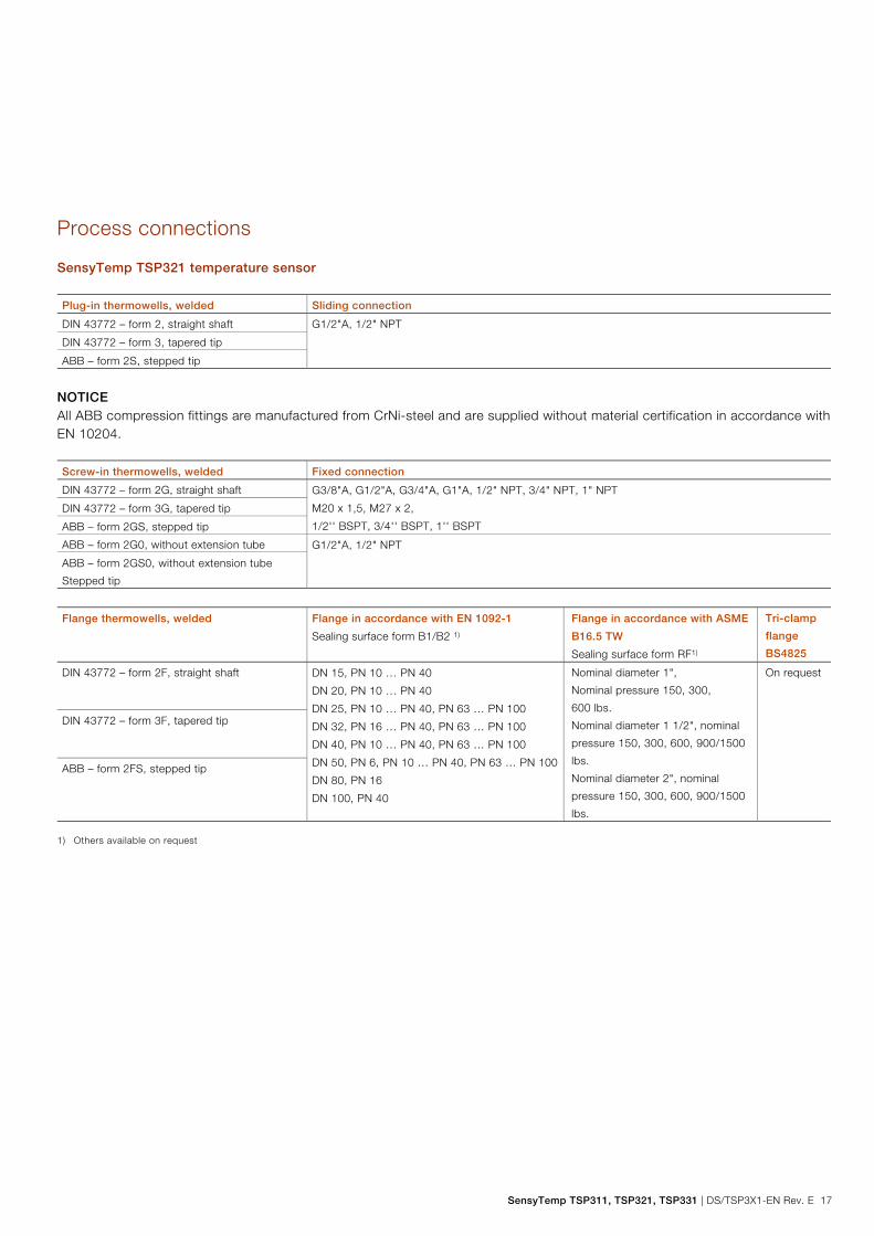
Process connections
SensyTemp TSP321 temperature sensor Plug-in thermowells, welded Sliding connection
DIN 43772 – form 2, straight shaft G1/2"A, 1/2" NPT
DIN 43772 – form 3, tapered tip
ABB – form 2S, stepped tip
NOTICE All ABB compression fittings are manufactured from CrNi-steel and are supplied without material certification in accordance with EN 10204. Screw-in thermowells, welded Fixed connection
DIN 43772 – form 2G, straight shaft G3/8"A, G1/2"A, G3/4"A, G1"A, 1/2" NPT, 3/4" NPT, 1" NPT
M20 x 1,5, M27 x 2,
1/2'' BSPT, 3/4'' BSPT, 1'' BSPT
DIN 43772 – form 3G, tapered tip
ABB – form 2GS, stepped tip
ABB – form 2G0, without extension tube G1/2"A, 1/2" NPT
ABB – form 2GS0, without extension tube
Stepped tip
Flange thermowells, welded Flange in accordance with EN 1092-1
Sealing surface form B1/B2 1)
Flange in accordance with ASME
B16.5 TW
Sealing surface form RF1)
Tri-clamp
flange
BS4825
DIN 43772 – form 2F, straight shaft DN 15, PN 10 … PN 40
DN 20, PN 10 … PN 40
DN 25, PN 10 … PN 40, PN 63 … PN 100
DN 32, PN 16 … PN 40, PN 63 … PN 100
DN 40, PN 10 … PN 40, PN 63 … PN 100
DN 50, PN 6, PN 10 … PN 40, PN 63 … PN 100
DN 80, PN 16
DN 100, PN 40
Nominal diameter 1",
Nominal pressure 150, 300,
600 lbs.
Nominal diameter 1 1/2", nominal
pressure 150, 300, 600, 900/1500
lbs.
Nominal diameter 2", nominal
pressure 150, 300, 600, 900/1500
lbs.
On request
DIN 43772 – form 3F, tapered tip
ABB – form 2FS, stepped tip
1) Others available on request

SensyTemp TSP311, TSP321, TSP331 Temperature sensors
18 DS/TSP3X1-EN Rev. E | SensyTemp TSP311, TSP321, TSP331
SensyTemp TSP331 temperature sensor Weld-in thermowells, drilled
Weld-in thermowells are available as DIN 43772 form 4 and ABB form PW. Other forms are available on request.
Screw-in thermowells, drilled Screw-in thread
DIN 43772 – form 6 and ABB form PS G1/2"A, 1/2" NPT, 3/4" NPT, 1" NPT, M20 x 1.5
Flange thermowells, drilled Flange in accordance with EN 1092-1
Sealing surface form B1/B2 1)
Flange in accordance with ASME
B16.5 TW
Sealing surface form RF1)
Tri-clamp
flange
BS4825
DIN 43772 – form 4F, F2 = 18 mm, 24 mm,
26 mm, thermowell manufactured from bar
stock material
DN 25, PN 10 … PN 40, PN 63 … PN 100
DN 32, PN 16 … PN 40
DN 40, PN 10 … PN 40, PN 63 … PN 100
DN 50, PN 6, PN 10 … PN 40, PN 63 … PN 100
DN 80, PN 16
DN 100, PN 40
Nominal diameter 1",
nominal pressure 150, 300,
600 lbs.
Nominal diameter 1 1/2", nominal
pressure 150, 300, 600,
900 / 1500 lbs.
Nominal diameter 2", nominal
pressure 150, 300, 600, 900/1500
lbs.
On request
ABB – form PF, thermowell manufactured from
bar stock material
1) Others available on request
NOTICE Other process connections are available on request. If required, contact your ABB partner. Change from one to two columns

SensyTemp TSP311, TSP321, TSP331 | DS/TSP3X1-EN Rev. E 19
Extension tubes The extension tube is the component between thermowell and connection head. It is used to bridge any existing insulation or serves as a cooling section between the temperature-sensitive electronics of the transmitter in the connection head and the process. The relation illustrated in Fig. 9 led to the selection of the standard extension tube with length K = 130 mm (5.12 inch). If the two threads are manufactured in one part (known as a double nipple), a minimum length of K = 25 mm (0.98 inch) is possible.
Fig. 9 A Overtemperature at the connection head compared to the ambient
temperature B Extension tube length T Flange temperature
Change from two to one column
Extension tube models Cylindrical screw-in
thread
Conical screw-in
thread
1/2'' NPT - 1/2'' NPT,
not separable (nipple)
1/2" NPT –
1/2" NPT, separable
(nipple-union)
1/2" NPT –
1/2" NPT, separable
(nipple-union-nipple)
Head connection M24 x 1.5 1/2" NPT
Thermowell connection G3/8", G1/2"
M14 x 1,5; M18 x 1,5;
M20 x 1,5;
1/2" NPT
Material 1.4571/316Ti
Change from one to two columns
A10018
800 °C (1472 °F)
620 °C (1148 °F)
430 °C (806 °F)
250 °C (482 °F)
75
2.95
100
3.94
125
4.92
175
6.98
200
7.87
225
8.86
150
5.91
250
9.84
0 32
10 50
20 68
30 86
mm
inch
40 104
50 122
60 140
°C °F
A
B
T
A11156 A11056
K
A11057
K
A11151
K
A11058
K
A11059
K

SensyTemp TSP311, TSP321, TSP331 Temperature sensors
20 DS/TSP3X1-EN Rev. E | SensyTemp TSP311, TSP321, TSP331
Connection heads
Functions of the connection head — Housing for a transmitter or coupler connector — Protection of the connection area against adverse
environmental effects When the connection cable is fed into the connection head, a special cable guide system automatically positions it inside the connection area. The flat base of the housing ensures optimum access to the connection area. A second cable entry is available as an option. Ambient temperature at connection head Connection head without transmitter and
without cable gland
-40 … 120 °C (-40 … 248 °F)
Connection head with transmitter -40 … 85 °C (-40 … 185 °F)
Connection head with LCD indicator -20 … 70 °C (-4 … 158 °F)
NOTICE In case of using in explosive environments, restrictions of the ambient temperature range are possible. The notes of the corresponding declarations of conformity and type examination certificate are to be followed.
The cable gland made of plastic used by default for cable outer diameter of 5.5 ... 13 mm (0.22 ... 0.51 inch) is suitable for a temperature range of -40 … 70 °C (-40 … 158 °F). For temperatures outside this range, an appropriate cable gland can be installed. The metal cable gland used for Ex-d (flameproof enclosure) by default for cable outer diameter of 3.2 ... 8.7 mm (0.13 ... 0.34 inch) covers the temperature range of -40 ... 120 °C (-40 ... 248 °F).
Change from two to one column
Head form AGL / AGS AGLH / AGSH AGLD / AGSD
Material AGL: Aluminum, epoxy-coated
AGS: Stainless steel
AGLH: Aluminum, epoxy-coated
AGS: Stainless steel
AGLH: Aluminum, epoxy-coated
AGS: Stainless steel
Cover locking system Screw-on cap
Cable gland M20 x 1.5, optional cable entry 1/2" NPTF, without cable gland
IP rating IP 66 / IP67
Transmitter mounting On the measuring inset On the mounting bracket
(mounting on the measuring inset
available as an option)
On the measuring inset
Dimensions in mm Change from one to two columns
115
~123
A11157
145
~123
A11158
125
~123
A11159

SensyTemp TSP311, TSP321, TSP331 | DS/TSP3X1-EN Rev. E 21
Transmitter
Installing a transmitter has the following advantages: — Decreased cost due to reduced wiring. — Amplification of the sensor signal at the measuring point
and conversion to a standard signal (thereby increasing the signal's interference immunity).
— Option to install an LCD indicator in the connection head. — SIL2 with accordingly classified transmitter. The output signal of a temperature sensor is determined by the selection of the corresponding transmitter. When using ABB transmitters, self-heating can be ignored. The following output signals are available: Type
TTH200 HART
4 … 20 mA, HART
TTH300 HART
4 … 20 mA, HART
TTH300 PA
PROFIBUS PA
TTH300 FF
FOUNDATION
Fieldbus H1
NOTICE Further information on the transmitters listed above can be found in the data sheets DS/TTH200 and DS/TTH300.
Type A and type AS LCD indicator
AGLD and AGSD connection heads are fitted with a digital LCD indicator. A suitable transmitter is connected via an add-on interface cable. We recommend using an LC display with type AS display function if you are using a TTH200. If the TTH300 transmitter is selected, the type A LCD indicator can also be used to configure the transmitter.
Fig. 10: A LCD indicator type A B LCD indicator type AS
1 Exit / Cancel 2 Scroll back 3 Scroll forwards 4 Select
Functional safety (SIL)
SensyTemp TSP temperature sensors with SIL certified transmitters fitted ex works are available with conformity in accordance with IEC 61508 for use in safety-related applications up to SIL 3 (redundant). When using a transmitter, the device fulfills the requirements in accordance with SIL 2. When using two redundant transmitters, the device fulfills the requirements in accordance with SIL 3. Information regarding functional safety for SensyTemp TSP temperature sensors can be found in the SIL safety instructions. Information about temperature sensors without built-in electronics can be found in the operating instruction.
A11232
A11233
A11234
A11235

SensyTemp TSP311, TSP321, TSP331 Temperature sensors
22 DS/TSP3X1-EN Rev. E | SensyTemp TSP311, TSP321, TSP331
Use in potentially explosive atmospheres in accordance with ATEX
Approvals TSP3X1 temperature sensors hold numerous approvals. These range from metrological approvals through Ex approvals for individual countries, ATEX certificates applicable across EU and in Switzerland up to internationally recognized IECEx documents. Specifically, these are: — ATEX Ex i PTB 01 ATEX 2200 X — ATEX dust ignition
protection BVS 06 ATEX E 029
— ATEX Ex d PTB 99 ATEX 1144 — Ex n (Zone 2 and 22) Declarations of conformity — IECEx — GOST / EAC Ex
Conditions for the use in potentially explosive areas The operator assumes responsibility for the proper installation according to the valid approval conditions when replacing the measuring inset in a thermometer. It is necessary to specify the production no. marked on the old part to ABB, so that ABB can examine the conformity of the ordered execution with the first delivery and the applicable approval. Thermal resistance The following table lists thermal resistances for measuring insets in diameter < 6.0 mm (0.24 inch) and ≥ 6.0 mm (0.24 inch). The values have been specified subject to the conditions "Gas with a flow velocity of 0 m/s" and "Measuring inset without or with an additional thermowell". Thermal resistance Rth
t = 200 K/W x 0.038 W = 7.6 K
Measuring inset
Ø < 6 mm
(0.24 inch)
Measuring inset
Ø ≥ 6 mm
(0.24 inch)
Without thermowell
Resistance thermometer 200 K/W 84 K/W
Thermocouple 30 K/W 30 K/W
With thermowell
Resistance thermometer 70 K/W 40 K/W
Thermocouple 30 K/W 30 K/W
K/W = kelvin per watt
Temperature rise in the event of a fault In the event of a fault, the temperature sensors will exhibit a temperature rise Δt as appropriate for the applied power. This Δt temperature rise must be taken into account with regard to the difference between process temperature and temperature class. NOTICE In the event of a fault (short-circuit), the dynamic short-circuit current that occurs in the measurement circuit for a matter of milliseconds is not relevant with regard to temperature rise. The Δt temperature rise can be calculated using the following formula: Δt = Rth × Po [K/W x W] — Δt = Temperature rise — Rth = Thermal resistance — Po = Output power of an additional connected
transmitter Example: Resistance thermometer diameter 3 mm (0.12 inch) without thermowell: Rth = 200 K/W, Temperature transmitter TTHXXX Po= 38 mW, see also "Output power Po for transmitters of ABB" on page 23. Δt = 200 K/W x 0.038 W = 7.6 K Therefore, at transmitter output power Po = 38 mW, the temperature rise in the event of a fault is approximately 8 K. This results in the following maximum possible process temperatures Tmedium, as shown in the table "Maximum process temperature Tmedium in Zone 0:" on page 23 .

SensyTemp TSP311, TSP321, TSP331 | DS/TSP3X1-EN Rev. E 23
Intrinsic safety ATEX "Ex i" Suitable thermowells in accordance with PTB 01 ATEX 2200 X are to be used. In the area of the electrical connections, the permissible ambient temperature range is -40 … 80° C (-40 … 176 °F). Electrical power limit Ex i All of the values listed below are valid assuming that an additional transmitter has been connected. The following electrical values must not be exceeded: Ui (input voltage) Ii (input current)
30 V 101 mA
25 V 158 mA
20 V 309 mA
Pi (internal power) = max. 0.5 W
Note: The internal power Pi corresponds to the output power Po of the
connected transmitter.
Li (internal inductance) = 15 μH/m
Ci (internal capacitance) = 280 pF/m
Output power Po for transmitters of ABB Transmitter type Po
TTH200 HART ≤ 38 mW
TTH300 HART ≤ 38 mW
TTH300 PA ≤ 38 mW
TTH300 FF ≤ 38 mW
All other information required to prove intrinsic safety (Uo, Io, Po, Lo, Co etc.) can be taken from the type examination certificates for the relevant transmitter models.
Maximum process temperature Tmedium in Zone 0: The surface temperature of Category 1 devices must not exceed 80 % of the ignition temperature of a flammable gas or liquid. For the temperature Tmedium, the temperature increase of 8 K in case of fault calculated as an example in chapter "Conditions for the use in potentially explosive areas" on page 22 is considered here. Temperature class 80 % of the ignition
temperature
Tmedium
T1 (450 °C (842 °F)) 360 °C (680 °F) 352 °C (665.5 °F)
T2 (300 °C (572 °F)) 240 °C (464 °F) 232 °C (449.6 °F)
T3 (200 °C (392 °F)) 160 °C (320 °F) 152 °C (305.6 °F)
T4 (135 °C (275 °F)) 108 °C (226.4 °F) 100 °C (212 °F)
T5 (100 °C (212 °F)) 80 °C (176 °F) 72 °C (161.6 °F)
T6 (85 °C (185 °F)) 68 °C (154.4 °F) 60 °C (140 °F)
Maximum process temperature Tmedium in Zone 1: To calculate the temperature classes for T3, T4, T5 and T6, 5 K in each instance must be deducted; for T1 and T2, 10 K in each instance must be deducted. Temperature class -5 K -10 K Tmedium
T1 (450 °C (842 °F)) – 440 °C
(824 °F)
432 °C
(809.6 °F)
T2 (300 °C (572 °F)) – 290 °C
(554 °F)
282 °C
(539.6 °F)
T3 (200 °C (392 °F)) 195 °C
(383 °F)
– 187 °C
(368.6 °F)
T4 (135 °C (275 °F)) 130 °C
(266 °F)
– 122 °C
(251.6 °F)
T5 (100 °C (212 °F)) 95 °C
(203 °F)
– 87 °C
(188.6 °F)
T6 (85 °C (185 °F)) 80 °C
(176 °F)
– 72 °C
(161.6 °F)
SensyTemp TSP311, TSP321, TSP331 Temperature sensors
24 DS/TSP3X1-EN Rev. E | SensyTemp TSP311, TSP321, TSP331
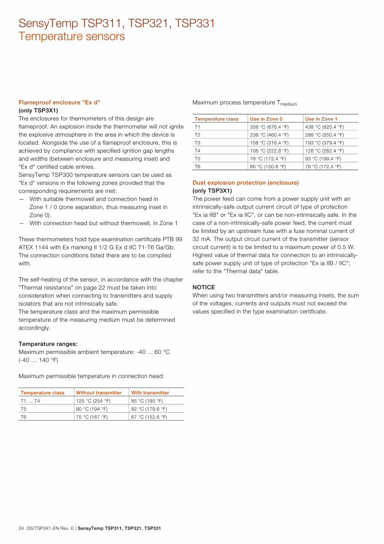
Flameproof enclosure "Ex d" (only TSP3X1) The enclosures for thermometers of this design are flameproof. An explosion inside the thermometer will not ignite the explosive atmosphere in the area in which the device is located. Alongside the use of a flameproof enclosure, this is achieved by compliance with specified ignition gap lengths and widths (between enclosure and measuring inset) and "Ex d" certified cable entries. SensyTemp TSP300 temperature sensors can be used as "Ex d" versions in the following zones provided that the corresponding requirements are met: — With suitable thermowell and connection head in
Zone 1 / 0 (zone separation, thus measuring inset in Zone 0).
— With connection head but without thermowell, in Zone 1 These thermometers hold type examination certificate PTB 99 ATEX 1144 with Ex marking II 1/2 G Ex d IIC T1-T6 Ga/Gb. The connection conditions listed there are to be complied with. The self-heating of the sensor, in accordance with the chapter "Thermal resistance" on page 22 must be taken into consideration when connecting to transmitters and supply isolators that are not intrinsically safe. The temperature class and the maximum permissible temperature of the measuring medium must be determined accordingly. Temperature ranges: Maximum permissible ambient temperature: -40 ... 60 °C (-40 … 140 °F) Maximum permissible temperature in connection head: Temperature class Without transmitter With transmitter
T1 … T4 125 °C (254 °F) 85 °C (185 °F)
T5 90 °C (194 °F) 82 °C (179.6 °F)
T6 75 °C (167 °F) 67 °C (152.6 °F)
Maximum process temperature Tmedium Temperature class Use in Zone 0 Use in Zone 1
T1 358 °C (676.4 °F) 438 °C (820.4 °F)
T2 238 °C (460.4 °F) 288 °C (550.4 °F)
T3 158 °C (316.4 °F) 193 °C (379.4 °F)
T4 106 °C (222.8 °F) 128 °C (262.4 °F)
T5 78 °C (172.4 °F) 93 °C (199.4 °F)
T6 66 °C (150.8 °F) 78 °C (172.4 °F)
Dust explosion protection (enclosure) (only TSP3X1) The power feed can come from a power supply unit with an intrinsically-safe output current circuit of type of protection "Ex ia IIB" or "Ex ia IIC", or can be non-intrinsically safe. In the case of a non-intrinsically-safe power feed, the current must be limited by an upstream fuse with a fuse nominal current of 32 mA. The output circuit current of the transmitter (sensor circuit current) is to be limited to a maximum power of 0.5 W. Highest value of thermal data for connection to an intrinsically-safe power supply unit of type of protection "Ex ia IIB / IIC"; refer to the "Thermal data" table. NOTICE When using two transmitters and/or measuring insets, the sum of the voltages, currents and outputs must not exceed the values specified in the type examination certificate.
Change from two to one column

SensyTemp TSP311, TSP321, TSP331 | DS/TSP3X1-EN Rev. E 25
Thermal data
Ap
pro
ved
am
bie
nt
tem
per
atur
e at
conn
ecti
on
head
Ap
pro
ved
pro
cess
tem
per
atur
e at
ther
mo
wel
l
Max
imum
tem
per
atur
e
at t
he p
roce
ss
conn
ecti
on
on
the
conn
ecti
on
head
sid
e
Max
imum
sur
face
tem
per
atur
e at
the
conn
ecti
on
head
Max
imum
sur
face
tem
per
atur
e at
the
ther
mo
wel
l
Category 1D or Category 1/2 with
intrinsically-safe transmitter installed
-40 ... 85 °C
(-40 ... 185 °F)
-40 ... 85 °C (-40 ... 185 °F)
-40 ... 200 °C (-40 … 392 °F)1)
-40 ... 300 °C (-40 … 572 °F)1)
-40 ... 400 °C (-40 … 752 °F)1)
85 °C (185 °F)
164 °C (327.2 °F)
251 °C (483.8 °F)
346 °C (654.8 °F)
120 °C (248 °F) 133 °C (271.4 °F)
200 °C (392 °F)
300 °C (572 °F)
400 °C (752 °F)
Category1D or Category1/2 with fuse
protection of installed transmitter by
means of external IEC fuse
-40 ... 85 °C
(-40 ... 185 °F)
-40 ... 85 °C (-40 ... 185 °F)
-40 ... 200 °C (-40 … 392 °F)1)
-40 ... 300 °C (-40 … 572 °F)1)
-40 ... 400 °C (-40 … 752 °F)1)
85 °C (185 °F)
164 °C (327.2 °F)
251 °C (483.8 °F)
346 °C (654.8 °F)
133 °C (271.4 °F)2)
150 °C (302 °F)3)
133 °C (271.4 °F)
200 °C (392 °F)
300 °C (572 °F)
400 °C (752 °F)
Category 1D or category 1/2D
measuring loop, intrinsically-safe
transmitter, external or non-intrinsically-
safe by means of external IEC fuse in
the power feed circuit of the external
transmitter
-40 ... 85 °C (-40 … 185 °F)
-40 ... 120 °C (-40 … 248 °F)
-40 ... 120 °C (-40 … 248 °F)
-40 ... 120 °C (-40 … 248 °F)
-40 ... 85 °C (-40 ... 185 °F)
-40 ... 200 °C (-40 … 392 °F)
-40 ... 300 °C (-40 … 572 °F)
-40 ... 400 °C (-40 … 752 °F)
85 °C (185 °F)
200 °C (392 °F)
251 °C (483.8 °F)
346 °C (654.8 °F)
85 °C (185 °F)
200 °C (392 °F)
200 °C (392 °F)
200 °C (392 °F)
133 °C (271.4 °F)
200 °C (392 °F)
300 °C (572 °F)
400 °C (752 °F)
1) The user must take suitable measures to ensure that the maximum permissible ambient temperature of 85 °C (185 °F) at the connection head is not exceeded. 2) Fitted with a transmitter with and without display. 3) Fitted with two transmitters.
Change from one to two columns
Non-sparking and dust explosion protection External measures must be made for the power supply circuit in order to prevent the rated voltage from being exceeded by more than 40% in the event of transient disturbances. The ambient temperature depends on the process temperature. The lower limit is -40 °C (-40 °F). The upper limit of the ambient temperature is presented in the following table:
Process temperature Extension tube
150 mm
Extension tube
250 mm
100 °C (212 °F) 65 °C (149 °F) 70 °C (158 °F)
200 °C (392 °F) 60 °C (140 °F) 70 °C (158 °F)
300 °C (572 °F) 60 °C (140 °F) 70 °C (158 °F)
400 °C (752 °F) 55 °C (131 °F) 65 °C (149 °F)
For integrated TTH200 or TTH300 transmitters and the T6 temperature class, the maximum permissible ambient temperature is 56 °C (132.8 °F). Process temperature:
max. 400 °C (752 °F) for II 3G max. 300 °C (572 °F) for II 3D

SensyTemp TSP311, TSP321, TSP331 Temperature sensors
26 DS/TSP3X1-EN Rev. E | SensyTemp TSP311, TSP321, TSP331
Tests and certificates
To increase the safety and accuracy of your process, ABB provides a number of mechanical and electrical tests. The results of these tests are certified in accordance with EN 10204. The following certificates are issued: — Declaration of compliance 2.1 for order conformity — Test report 2.2 for the following tests:
— Material of wetted parts — Batch values of the thermocouple — Insulation resistance measurement at room
temperature — Inspection certificate 3.1 for the following tests:
— Material confirmation for wetted parts — Visual, dimensional and function checks of
temperature sensor — Helium leak test for thermowell — X-ray inspection of thermowell for bore hole
concentricity on request — X-ray inspection of weld seams — Ultrasonic test for bore hole concentricity — Dye penetration test at the weld seams of the
thermowell — Compression test of thermowell — Measuring inset reference measurement
— Inspection certificate 3.2 available on request
For measurements requiring extremely high accuracy, ABB can calibrate the temperature sensor in its own DAkkS-calibration lab. When DAkkS- calibration is performed, a separate certificate is provided for each temperature sensor. Reference measurements and DAkkS calibrations are performed on the measuring inset, together with a transmitter if necessary. To obtain accurate measurements, observe the minimum length for the measuring inset's mineral insulated cable: — In very low temperatures (< -70° C (-94 °F)): 300 mm — In low to medium temperatures: 100 ... 150 mm — In temperatures over 500 °C (932 °F): 300 ... 400 mm Longer lengths allow additional measurement methods and simplify the measuring process. If you require any further information, please contact your local ABB partner. For reference measurements and DAkkS-calibration, the individual characteristic of the temperature sensor can also be calculated and a suitable transmitter can be programmed based on a freestyle characteristic. Adjusting the transmitter to the sensor characteristic can considerably improve the measuring accuracy of the temperature sensor. The measurement must be taken with at least three temperatures.
Change from two to one column
SensyTemp TSP311, TSP321, TSP331 | DS/TSP3X1-EN Rev. E 27
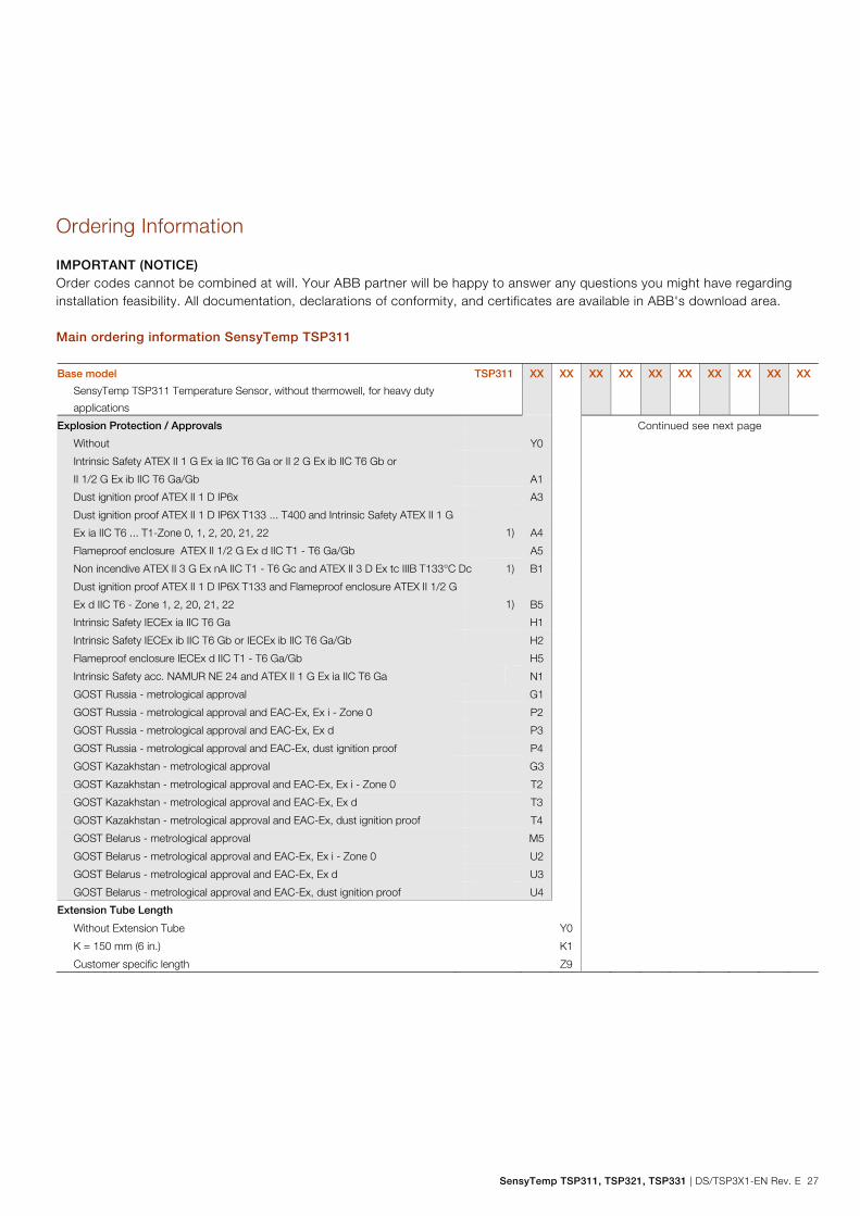
Ordering Information
IMPORTANT (NOTICE) Order codes cannot be combined at will. Your ABB partner will be happy to answer any questions you might have regarding installation feasibility. All documentation, declarations of conformity, and certificates are available in ABB's download area. Main ordering information SensyTemp TSP311 Base model
SensyTemp TSP311 Temperature Sensor, without thermowell, for heavy duty
applications
TSP311 XX XX XX XX XX XX XX XX XX XX
Explosion Protection / Approvals Continued see next page
Without Y0
Intrinsic Safety ATEX II 1 G Ex ia IIC T6 Ga or II 2 G Ex ib IIC T6 Gb or
II 1/2 G Ex ib IIC T6 Ga/Gb
A1
Dust ignition proof ATEX II 1 D IP6x A3
Dust ignition proof ATEX II 1 D IP6X T133 ... T400 and Intrinsic Safety ATEX II 1 G
Ex ia IIC T6 ... T1-Zone 0, 1, 2, 20, 21, 22
1)
A4
Flameproof enclosure ATEX II 1/2 G Ex d IIC T1 - T6 Ga/Gb A5
Non incendive ATEX II 3 G Ex nA IIC T1 - T6 Gc and ATEX II 3 D Ex tc IIIB T133°C Dc 1) B1
Dust ignition proof ATEX II 1 D IP6X T133 and Flameproof enclosure ATEX II 1/2 G
Ex d IIC T6 - Zone 1, 2, 20, 21, 22
1)
B5
Intrinsic Safety IECEx ia IIC T6 Ga H1
Intrinsic Safety IECEx ib IIC T6 Gb or IECEx ib IIC T6 Ga/Gb H2
Flameproof enclosure IECEx d IIC T1 - T6 Ga/Gb H5
Intrinsic Safety acc. NAMUR NE 24 and ATEX II 1 G Ex ia IIC T6 Ga N1
GOST Russia - metrological approval G1
GOST Russia - metrological approval and EAC-Ex, Ex i - Zone 0 P2
GOST Russia - metrological approval and EAC-Ex, Ex d P3
GOST Russia - metrological approval and EAC-Ex, dust ignition proof P4
GOST Kazakhstan - metrological approval G3
GOST Kazakhstan - metrological approval and EAC-Ex, Ex i - Zone 0 T2
GOST Kazakhstan - metrological approval and EAC-Ex, Ex d T3
GOST Kazakhstan - metrological approval and EAC-Ex, dust ignition proof T4
GOST Belarus - metrological approval M5
GOST Belarus - metrological approval and EAC-Ex, Ex i - Zone 0 U2
GOST Belarus - metrological approval and EAC-Ex, Ex d U3
GOST Belarus - metrological approval and EAC-Ex, dust ignition proof U4
Extension Tube Length
Without Extension Tube Y0
K = 150 mm (6 in.) K1
Customer specific length Z9

SensyTemp TSP311, TSP321, TSP331 Temperature sensors
28 DS/TSP3X1-EN Rev. E | SensyTemp TSP311, TSP321, TSP331
Main ordering information SensyTemp TSP311 XX XX XX XX XX XX XX XX
Thermowell Connection
Continued see next page No extension / Connection head with thread M24 x 1,5 W1
No extension / Connection head with thread 1/2 in. NPT W2
No extension / Connection head with lock nut M24 x 1.5 W3
Double nipple / G 1/2 A / G 1/2 A W4
Double nipple / 1/2 in. NPT / 1/2 in. NPT W5
Extension tube with Cylindrical thread G 1/2 A G1
Extension tube with Cylindrical thread G 3/4 A G2
Extension tube with Cylindrical thread G 3/8 A G3
Extension tube with Cylindrical thread M14 x 1,5 M1
Extension tube with Cylindrical thread M18 x 1,5 M2
Extension tube with Cylindrical thread M20 x 1,5 M3
Extension tube with Cylindrical thread M24 x 1,5 M4
Extension tube with Cylindrical thread M27 x 2 M5
Extension tube with conycal thread 1/2 in. NPT N1
Nipple / 1/2 in. NPT / 1/2 in. NPT N2
Nipple-Union / 1/2 in. NPT / Union 1/2 in. NPT N3
Nipple - Union - Nipple / 1/2 in. NPT / 1/2 in. NPT N4
Extension with Male nut, thread G 1/2 in. U6
Extension tube with adjustable compression fitting G 1/2 A A1
Extension tube with adjustable compression fitting 1/2 in. NPT A2
Others Z9
Immersion Length
U = 140 mm (5.6 in.) U2
U = 200 mm (8 in.) U4
U = 260 mm (10.3 in.) U6
Customer specific length Z9
SensyTemp TSP311, TSP321, TSP331 | DS/TSP3X1-EN Rev. E 29
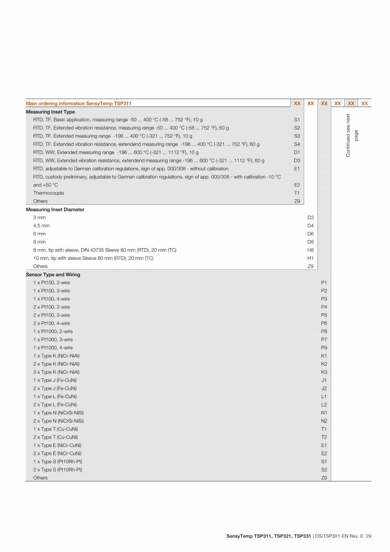
Main ordering information SensyTemp TSP311 XX XX XX XX XX XX
Measuring Inset Type
Con
tinue
d se
e ne
xt
page
RTD, TF, Basic application, measuring range -50 ... 400 °C (-58 ... 752 °F), 10 g S1
RTD, TF, Extended vibration resistance, measuring range -50 ... 400 °C (-58 ... 752 °F), 60 g S2
RTD, TF, Extended measuring range -196 ... 400 °C (-321 ... 752 °F), 10 g S3
RTD, TF, Extended vibration resistance, extendend measuring range -196 ... 400 °C (-321 ... 752 °F), 60 g S4
RTD, WW, Extended measuring range -196 ... 600 °C (-321 ... 1112 °F), 10 g D1
RTD, WW, Extended vibration resistance, extendend measuring range -196 ... 600 °C (-321 ... 1112 °F), 60 g D3
RTD, adjustable to German calibration regulations, sign of app. 000/308 - without calibration E1
RTD, custody preliminary, adjustable to German calibration regulations, sign of app. 000/308 - with calibration -10 °C
and +50 °C
E2
Thermocouple T1
Others Z9
Measuring Inset Diameter
3 mm D3
4.5 mm D4
6 mm D6
8 mm D8
8 mm, tip with sleeve, DIN 43735 Sleeve 80 mm (RTD), 20 mm (TC) H8
10 mm, tip with sleeve Sleeve 80 mm (RTD), 20 mm (TC) H1
Others Z9
Sensor Type and Wiring
1 x Pt100, 2-wire P1
1 x Pt100, 3-wire P2
1 x Pt100, 4-wire P3
2 x Pt100, 2-wire P4
2 x Pt100, 3-wire P5
2 x Pt100, 4-wire P6
1 x Pt1000, 2-wire P8
1 x Pt1000, 3-wire P7
1 x Pt1000, 4-wire P9
1 x Type K (NiCr-NiAl) K1
2 x Type K (NiCr-NiAl) K2
3 x Type K (NiCr-NiAl) K3
1 x Type J (Fe-CuNi) J1
2 x Type J (Fe-CuNi) J2
1 x Type L (Fe-CuNi) L1
2 x Type L (Fe-CuNi) L2
1 x Type N (NiCrSi-NiSi) N1
2 x Type N (NiCrSi-NiSi) N2
1 x Type T (Cu-CuNi) T1
2 x Type T (Cu-CuNi) T2
1 x Type E (NiCr-CuNi) E1
2 x Type E (NiCr-CuNi) E2
1 x Type S (Pt10Rh-Pt) S1
2 x Type S (Pt10Rh-Pt) S2
Others Z9

SensyTemp TSP311, TSP321, TSP331 Temperature sensors
30 DS/TSP3X1-EN Rev. E | SensyTemp TSP311, TSP321, TSP331
Main ordering information SensyTemp TSP311 XX XX XX
Sensor Accuracy
Accuracy Class B, IEC 60751 B2
Wire Wound, Double, Accuracy Class A, IEC 60751, Range 0 ... 250 °C (32 ... 482 °F) D2
Wire Wound, Accuracy Class A, IEC 60751, Range -100 ... 450 °C (-148 ... 842 °F) D1
Thin Film, Accuracy Class A, IEC 60751, Range -30 ... 300 °C (-22 ... 572 °F) S1
Thin Film, Accuracy Class AA, IEC 60751, Range 0 ... 100 °C (0 ... 212 °F) S3
Thin Film, Accuracy Class A extended according to IEC 60751, Range -196 ... 400 °C (-320,8 ... 752 °F) S6
Thin Film, Accuracy Class AA extended according to IEC 60751, Range -196 ... 400 °C (-320,8 ... 752 °F) S8
Thermocouple, Accuracy Class 2, IEC 60584 T2
Thermocouple, Accuracy Class 1, IEC 60584 T1
Thermocouple, Standard Accuracy ANSI MC96.1 T4
Thermocouple, Special Accuracy ANSI MC96.1 T3
Thermocouple, Accuracy according to DIN 43710 T5
Others Z9
Connection Head Type / Material
AGL / Aluminium, screwed cover L1
AGLH / Aluminium, high cover, screwed L2
AGLD / Aluminium, screwed cover with display L4
AGS / Stainless steel, screwed cover S1
AGSH / Stainless steel, high cover, screwed S2
AGSD / Stainless steel, screwed cover with display S4
Others Z9
Transmitter
Without transmitter, sensor with ceramic terminal block - spring loaded Y1
Without transmitter, sensor with flying leads and metal plate - spring loaded Y2
TTH300-HART, programmable, output signal 4 ... 20 mA, dual input H4
TTH300-HART, Ex version, programmable, output signal 4 ... 20 mA, dual input H5
TTH300-PA, programmable, output PROFIBUS PA, dual input P6
TTH300-PA, Ex version, programmable, output PROFIBUS PA, dual input P7
TTH300-FF, programmable, output FOUNDATION fieldbus H1, dual input F6
TTH300-FF, Ex version, programmable, output FOUNDATION fieldbus H1, dual input F7
TTH200-HART, programmable, output signal 4 ... 20 mA H6
TTH200-HART, Ex version, programmable, output signal 4 ... 20 mA H7

SensyTemp TSP311, TSP321, TSP331 | DS/TSP3X1-EN Rev. E 31
Additional ordering information SensyTemp TSP311 XX XX XX
Transmitter Measuring Range
Standard measuring range A0
Customer-specific measuring range AZ
Certificates
Declaration of compliance according EN 10204-2.1, with the order C4
Test report according EN 10204-2.2 for batch values, MIC-TC C5
Test report according EN 10204-2.2 for measuring of insulaionsresistance at ambient temperature CN
Inspection certificate according EN 10204-3.1, visual, dimensional and functional test C6
Inspection certificate according EN 10204-3.1, helium leakage test C7
Inspection certificate according EN 10204-3.1, sensor tolerance CC
TÜV certificate for functional safety SIL2 IEC 61508 for sensor with integrated transmitter, HART CS
Inspection certificate according EN 10204-3.1, sensor calibration, single RTD CD
Inspection certificate according EN 10204-3.1, sensor calibration, double RTD CE
Inspection certificate according EN 10204-3.1, sensor calibration, single thermocouple CF
Inspection certificate according EN 10204-3.1, sensor calibration, double thermocouple CG
DAkkS sensor calibration, single RTD, calibration certificate per thermometer CH
DAkkS sensor calibration, double RTD, calibration certificate per thermometer CJ
DAkkS sensor calibration, single thermocouple, calibration certificate per thermometer CK
DAkkS sensor calibration, double thermocouple, calibration certificate per thermometer CL
Others CZ
Number of Calibration Test Points
1 point P1
2 points P2
3 points P3
4 points P4
5 points P5

SensyTemp TSP311, TSP321, TSP331 Temperature sensors
32 DS/TSP3X1-EN Rev. E | SensyTemp TSP311, TSP321, TSP331
Additional ordering information SensyTemp TSP311 XX XX XX
Temperatures for Sensor Calibration
Standard calibration: 0 °C (32 °F) V1
Standard calibration: 100 °C (212 °F) V2
Standard calibration: 400 °C (752 °F) V3
Standard calibration: 0 °C and 100 °C (32 °F and 212 °F) V4
Standard calibration: 0 °C and 400 °C (32 °F and 752 °F) V5
Standard calibration: 0 °C, 100 °C and 200 °C (32 °F, 212 °F and 392 °F) V7
Standard calibration: 0 °C, 200 °C and 400 °C (32 °F, 392 °F and 752 °F) V8
Standard calibration: Customer specific temperatures V6
DAkkS calibration: 0 °C (32 °F) D1
DAkkS calibration: 100 °C (212 °F) D2
DAkkS calibration: 400 °C (752 °F) D3
DAkkS calibration: 0 °C and 100 °C (32 °F and 212 °F) D4
DAkkS calibration: 0 °C and 400 °C (32 °F and 752 °F) D5
DAkkS calibration: 0 °C, 100 °C and 200 °C (32 °F, 212 °F and 392 °F) D7
DAkkS calibration: 0 °C, 200 °C and 400 °C (32 °F, 392 °F and 752 °F) D8
DAkkS calibration: Customer specific temperatures D6
Extension Tube Options
Extension tube welded with measuring inset, gas tight N3
Extension tube oil tight up to 3bar N4
Mounting bracket N5
Threaded Connection Options
Adjustable compression fitting G 1/4, stainless steel material K1
Adjustable compression fitting G 1/4, stainless steel material, olive material PTFE K2
Adjustable compression fitting G 1/2, stainless steel material K3
Adjustable compression fitting G 1/2, stainless steel material, olive material PTFE K4
Adjustable compression fitting M18 x 1.5, stainless steel material K5
Adjustable compression fitting 1/2 in. NPT, stainless steel material K6
Adjustable compression fitting 1/2 in. NPT, stainless steel material, olive material PTFE K7
Spring loaded adjustable compression fitting G 1/2 , stainless steel material K8
Spring loaded adjustable compression fitting M18 x 1.5, stainless steel material K9
Others KZ
SensyTemp TSP311, TSP321, TSP331 | DS/TSP3X1-EN Rev. E 33
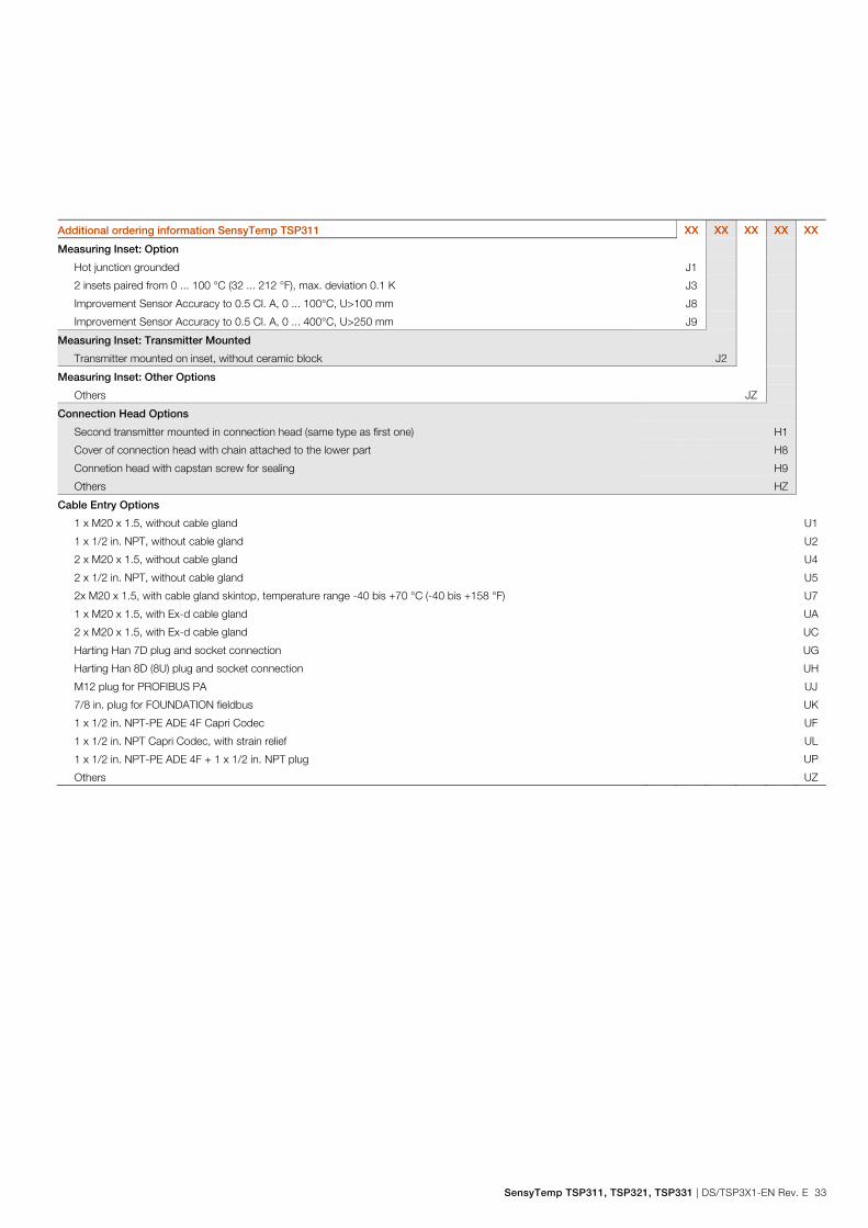
Additional ordering information SensyTemp TSP311 XX XX XX XX XX
Measuring Inset: Option
Hot junction grounded J1
2 insets paired from 0 ... 100 °C (32 ... 212 °F), max. deviation 0.1 K J3
Improvement Sensor Accuracy to 0.5 Cl. A, 0 ... 100°C, U>100 mm J8
Improvement Sensor Accuracy to 0.5 Cl. A, 0 ... 400°C, U>250 mm J9
Measuring Inset: Transmitter Mounted
Transmitter mounted on inset, without ceramic block J2
Measuring Inset: Other Options
Others JZ
Connection Head Options
Second transmitter mounted in connection head (same type as first one) H1
Cover of connection head with chain attached to the lower part H8
Connetion head with capstan screw for sealing H9
Others HZ
Cable Entry Options
1 x M20 x 1.5, without cable gland U1
1 x 1/2 in. NPT, without cable gland U2
2 x M20 x 1.5, without cable gland U4
2 x 1/2 in. NPT, without cable gland U5
2x M20 x 1.5, with cable gland skintop, temperature range -40 bis +70 °C (-40 bis +158 °F) U7
1 x M20 x 1.5, with Ex-d cable gland UA
2 x M20 x 1.5, with Ex-d cable gland UC
Harting Han 7D plug and socket connection UG
Harting Han 8D (8U) plug and socket connection UH
M12 plug for PROFIBUS PA UJ
7/8 in. plug for FOUNDATION fieldbus UK
1 x 1/2 in. NPT-PE ADE 4F Capri Codec UF
1 x 1/2 in. NPT Capri Codec, with strain relief UL
1 x 1/2 in. NPT-PE ADE 4F + 1 x 1/2 in. NPT plug UP
Others UZ

SensyTemp TSP311, TSP321, TSP331 Temperature sensors
34 DS/TSP3X1-EN Rev. E | SensyTemp TSP311, TSP321, TSP331
Additional ordering information SensyTemp TSP311 XX XX XX XX XX
Display Type
LCD indicator type AS L1
Configurable LCD Indicator type A L2
Other Options
With fastened gasket PD
Earth screw internal PH
Name plate stanless steel PV
Each Thermometer single packed - Polyethylen PN
Documentation Language
German M1
English M5
Language package Western Europe / Scandinavia (Languages: DA, ES, FR, IT, NL, PT, FI, SV) MW
Language package Eastern Europe (Languages: EL, CS, ET, LV, LT, HU, HR, PL, SK, SL, RO, BG) ME
Additional TAG Plate
Stainless steel plate with TAG no. T1
Additional Identification Plate
Stainless steel plate with customer specific text T2
Adhesive label T3 1) According EN 60079-0 and EN 61241-0, the application in hybrid mixtures (concomitance of potentially explosive dust and gas) is currently not allowed.

SensyTemp TSP311, TSP321, TSP331 | DS/TSP3X1-EN Rev. E 35
Main ordering information SensyTemp TSP321 Base model
SensyTemp TSP321 Temperature Sensor, with tubular thermowell,
for heavy duty applications
TSP321 XX XX XX XX XX XX XX XX XX XX XX XX
Explosion Protection / Approvals Continued see next page
Without Y0
Intrinsic Safety ATEX II 1 G Ex ia IIC T6 Ga or II 2 G Ex ib IIC T6 Gb or
II 1/2 G Ex ib IIC T6 Ga/Gb
A1
Dust ignition proof ATEX II 1 D IP6x A3
Dust ignition proof ATEX II 1 D IP6X T133 ... T400 and Intrinsic Safety
ATEX II 1 G Ex ia IIC T6 ... T1-Zone 0, 1, 2, 20, 21, 22
1)
A4
Flameproof enclosure ATEX II 1/2 G Ex d IIC T1 - T6 Ga/Gb A5
Non incendive ATEX II 3 G Ex nA IIC T1 - T6 Gc and
ATEX II 3 D Ex tc IIIB T133°C Dc
1)
B1
Dust ignition proof ATEX II 1 D IP6X T133 and Flameproof enclosure
ATEX II 1/2 G Ex d IIC T6 - Zone 1, 2, 20, 21, 22
1)
B5
Intrinsic Safety IECEx ia IIC T6 Ga H1
Intrinsic Safety IECEx ib IIC T6 Gb or IECEx ib IIC T6 Ga/Gb H2
Flameproof enclosure IECEx d IIC T1 - T6 Ga/Gb H5
Intrinsic Safety acc. NAMUR NE 24 and ATEX II 1 G Ex ia IIC T6 Ga N1
GOST Russia - metrological approval G1
GOST Russia - metrological approval and EAC-Ex, Ex i - Zone 0 P2
GOST Russia - metrological approval and EAC-Ex, Ex d P3
GOST Russia - metrological approval and EAC-Ex, dust ignition proof P4
GOST Kazakhstan - metrological approval G3
GOST Kazakhstan - metrological approval and EAC-Ex, Ex i - Zone 0 T2
GOST Kazakhstan - metrological approval and EAC-Ex, Ex d T3
GOST Kazakhstan - metrological approval and EAC-Ex, dust ignition proof T4
GOST Belarus - metrological approval M5
GOST Belarus - metrological approval and EAC-Ex, Ex i - Zone 0 U2
GOST Belarus - metrological approval and EAC-Ex, Ex d U3
GOST Belarus - metrological approval and EAC-Ex, dust ignition proof U4

SensyTemp TSP311, TSP321, TSP331 Temperature sensors
36 DS/TSP3X1-EN Rev. E | SensyTemp TSP311, TSP321, TSP331
Main ordering information SensyTemp TSP321 XX XX XXX XX XX XX XX XX XX XX XX
Wetted Thermowell Material
Stainless Steel ASTM 316L (1.4404) S1 Continued see next page
Stainless Steel ASTM 316Ti (1.4571) S2
Highly heat-resistant stainless steel ASTM A446-1 (1.4749) H1
Heat Resistent Steel 1.4762 H2
Stainless Steel AISI 314 (1.4841) H3
Duplex stainless steel (CrNi, 1.4462) S9
Stainless steel ASTM 904L (CrNi, 1.4539); (Uranus B6) S4
Ni-Alloy Hastelloy C-276 (2.4819) N1
Ni-Alloy Hastelloy C-4 (2.4610) N2
Highly heat-resistant stainless steel , Ni-Alloy Inconel 600 (2.4816) N5
Others Z9
Thermowell Type
Tubular thermowell with straight shaft (DIN 43772, Form 2) A1
Flanged tubular thermowell with straight shaft (DIN 43772, Form 2F) A2
Screwed tubular thermowell with straight shaft (DIN 43772, Form 2G) A3
Tubular thermowell, stepped tip (ABB Form 2S) B1
Flanged tubular thermowell, stepped tip (ABB Form 2FS) B2
Screwed tubular thermowell, stepped tip (ABB Form 2GS) B3
Tubular thermowell, tapered (DIN 43772, Form 3) C1
Flanged tubular thermowell, tapered (DIN 43772, Form 3F) C2
Screwed tubular thermowell, tapered (DIN 43772, Form 3G) C3
Screwed tubular thermowell without extension, straight shaft (ABB Form 2G0) A4
Screwed tubular thermowell without extension, stepped tip (ABB Form 2GS0) B4
Tubular thermowell d= 22mm, stepped tip d= 6mm B5
Tubular thermowell, stepped tip 9 mm (0.36 in.) (ABB Form 2S/9) K1
Flanged tubular thermowell, stepped tip 9 mm (0.36 in.) (ABB Form 2FS/9) K2
Screwed tubular thermowell, stepped tip 9 mm (0.36 in.) (ABB Form 2GS/9) K3
Others Z9

SensyTemp TSP311, TSP321, TSP331 | DS/TSP3X1-EN Rev. E 37
Main ordering information SensyTemp TSP321 XXX XX XX XX XX XX XX XX XX
Process Connection
Without process connection Y00 Continued see next page
Adjustable compression fitting G 1/2, stainless steel A01
Adjustable compression fitting 1/2 in. NPT, stainless steel A02
Adjustable flange DN 25 PN 10 ... PN 40, EN 1092-1 A03
Adjustable flange 1 in. 150 lbs, ASME B16.5 A07
Flange DN 15 PN 10 ... PN 40, EN 1092-1 F01
Flange DN 20 PN 10 ... PN 40, EN 1092-1 F02
Flange DN 25 PN 10 ... PN 40, EN 1092-1 F03
Flange DN 25 PN 63 ... PN100, EN 1092-1 F29
Flange DN 32 PN 16 … PN 40, EN 1092-1 F30
Flange DN 40 PN 10 ... PN 40, EN 1092-1 F04
Flange DN 40 PN 63 ... PN 100, EN 1092-1 F37
Flange DN 50 PN 6, EN 1092-1 F06
Flange DN 50 PN 10 ... PN 40, EN 1092-1 F05
Flange DN 50 PN 63, EN 1092-1 F33
Flange DN 50 PN 100, EN 1092-1 F34
Flange DN 80 PN 16, EN 1092-1 F35
Flange DN 100 PN 40, EN 1092-1 F36
Flange 1 in. 150 lbs, ASME B16.5 F07
Flange 1 in. 300 lbs, ASME B16.5 F08
Flange 1 in. 600 lbs, ASME B16.5 F09
Flange 1-1/2 in. 150 lbs, ASME B16.5 F11
Flange 1-1/2 in. 300 lbs, ASME B16.5 F12
Flange 1-1/2 in. 600 lbs, ASME B16.5 F13
Flange 1-1/2 in. 900 / 1500 lbs, ASME B16.5 F14
Flange 2 in. 150 lbs, ASME B16.5 F15
Flange 2 in. 300 lbs, ASME B16.5 F16
Flange 2 in. 600 lbs, ASME B16.5 F17
Flange 2 in. 900 / 1500 lbs, ASME B16.5 F18
Cylindrical thread G 3/8 A S15
Cylindrical thread G 1/2 A S01
Cylindrical thread G 3/4 A S02
Cylindrical thread G 1 A S03
Cylindrical thread M20 x 1.5 S07
Cylindrical thread M27 x 2 S08
Conical thread 1/2 in. NPT S04
Conical thread 3/4 in. NPT S05
Conical thread 1 in. NPT S06
Conical thread 1/2 in. BSPT S09
Conical thread 3/4 in. BSPT S10
Conical thread 1 in. BSPT S11
Others Z99

SensyTemp TSP311, TSP321, TSP331 Temperature sensors
38 DS/TSP3X1-EN Rev. E | SensyTemp TSP311, TSP321, TSP331
Main ordering information SensyTemp TSP321 XX XX XX XX XX XX XX XX
Thermowell Diameter
6 mm x 1 mm A9 Continued see next
page 8 mm x 2 mm A5
9 mm x 1 mm A1
10 mm x 1,5 mm A6
11 mm x 2 mm A2
12 mm x 2,5 mm A3
13,5 mm x 2,3 mm B6
13,7 mm x 2,24 mm B2
14 mm x 2,5 mm A4
15 mm x 2 mm A7
16 mm x 3 mm A8
22 mm x 2 mm B1
Immersion Length
Without fixed immersion length Y0
U = 100 mm (4 in.) U1
U = 160 mm (6.3 in.) U3
U = 250 mm (10 in.) U5
U = 400 mm (16 in.) U7
Customer specific length Z9
Nominal Length
N = 230 mm (9.1 in.) N1
N = 290 mm (11.42 in.) N3
N = 380 mm (15 in.) N5
N = 530 mm (20.9 in.) N7
Customer specific length Z9
Measuring Inset Type
Without measuring inset Y0
RTD, TF, Basic application, measuring range -50 ... 400 °C (-58 ... 752 °F), 10 g S1
RTD, TF, Extended vibration resistance, measuring range -50 ... 400 °C (-58 ... 752 °F), 60 g S2
RTD, TF, Extended measuring range -196 ... 400 °C (-321 ... 752 °F), 10 g S3
RTD, TF, Extended vibration resistance, extendend measuring range -196 ... 400 °C (-321 ... 752 °F), 60 g S4
RTD, WW, Extended measuring range -196 ... 600 °C (-321 ... 1112 °F), 10 g D1
RTD, WW, Extended vibration resistance, extendend measuring range -196 ... 600 °C (-321 ... 1112 °F), 60 g D3
RTD, adjustable to German calibration regulations, sign of app. 000/308 - without calibration E1
RTD, custody preliminary, adjustable to German calibration regulations, sign of app. 000/308 - with calibration -10 °C
and +50 °C
E2
Thermocouple T1
Others Z9
SensyTemp TSP311, TSP321, TSP331 | DS/TSP3X1-EN Rev. E 39
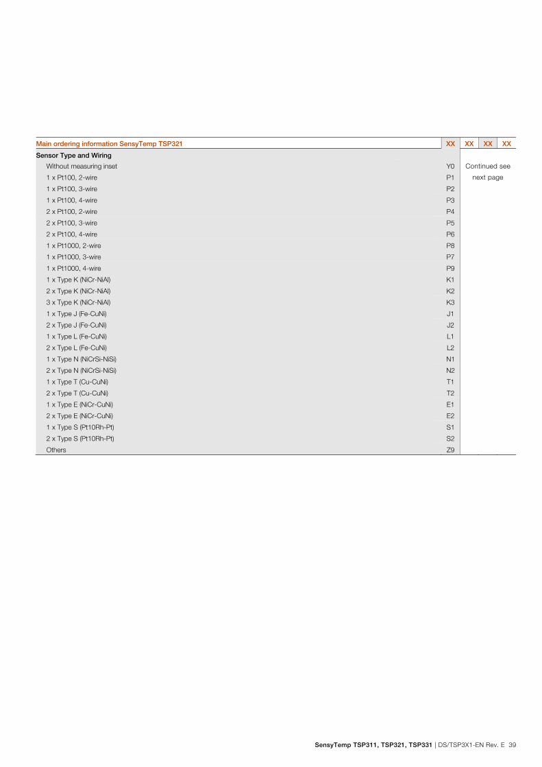
Main ordering information SensyTemp TSP321 XX XX XX XX
Sensor Type and Wiring
Without measuring inset Y0 Continued see
next page 1 x Pt100, 2-wire P1
1 x Pt100, 3-wire P2
1 x Pt100, 4-wire P3
2 x Pt100, 2-wire P4
2 x Pt100, 3-wire P5
2 x Pt100, 4-wire P6
1 x Pt1000, 2-wire P8
1 x Pt1000, 3-wire P7
1 x Pt1000, 4-wire P9
1 x Type K (NiCr-NiAl) K1
2 x Type K (NiCr-NiAl) K2
3 x Type K (NiCr-NiAl) K3
1 x Type J (Fe-CuNi) J1
2 x Type J (Fe-CuNi) J2
1 x Type L (Fe-CuNi) L1
2 x Type L (Fe-CuNi) L2
1 x Type N (NiCrSi-NiSi) N1
2 x Type N (NiCrSi-NiSi) N2
1 x Type T (Cu-CuNi) T1
2 x Type T (Cu-CuNi) T2
1 x Type E (NiCr-CuNi) E1
2 x Type E (NiCr-CuNi) E2
1 x Type S (Pt10Rh-Pt) S1
2 x Type S (Pt10Rh-Pt) S2
Others Z9

SensyTemp TSP311, TSP321, TSP331 Temperature sensors
40 DS/TSP3X1-EN Rev. E | SensyTemp TSP311, TSP321, TSP331
Main ordering information SensyTemp TSP321 XX XX XX
Sensor Accuracy
Without measuring inset Y0
Accuracy Class B, IEC 60751 B2
Wire Wound, Double, Accuracy Class A, IEC 60751, Range 0 ... 250 °C (32 ... 482 °F) D2
Wire Wound, Accuracy Class A, IEC 60751, Range -100 ... 450 °C (-148 ... 842 °F) D1
Thin Film, Accuracy Class A, IEC 60751, Range -30 ... 300 °C (-22 ... 572 °F) S1
Thin Film, Accuracy Class AA, IEC 60751, Range 0 ... 100 °C (0 ... 212 °F) S3
Thin Film, Accuracy Class A extended according to IEC 60751, Range -196 ... 400 °C (-320,8 ... 752 °F) S6
Thin Film, Accuracy Class AA extended according to IEC 60751, Range -196 ... 400 °C (-320,8 ... 752 °F) S8
Thermocouple, Accuracy Class 2, IEC 60584 T2
Thermocouple, Accuracy Class 1, IEC 60584 T1
Thermocouple, Standard Accuracy ANSI MC96.1 T4
Thermocouple, Special Accuracy ANSI MC96.1 T3
Thermocouple, Accuracy according to DIN 43710 T5
Others Z9
Connection Head Type / Material
AGL / Aluminium, screwed cover L1
AGLH / Aluminium, high cover, screwed L2
AGLD / Aluminium, screwed cover with display L4
AGS / Stainless steel, screwed cover S1
AGSH / Stainless steel, high cover, screwed S2
AGSD / Stainless steel, screwed cover with display S4
Others Z9
Transmitter
Without transmitter, sensor with ceramic terminal block - spring loaded Y1
Without transmitter, sensor with flying leads and metal plate - spring loaded Y2
TTH300-HART, programmable, output signal 4 ... 20 mA, dual input H4
TTH300-HART, Ex version, programmable, output signal 4 ... 20 mA, dual input H5
TTH300-PA, programmable, output PROFIBUS PA, dual input P6
TTH300-PA, Ex version, programmable, output PROFIBUS PA, dual input P7
TTH300-FF, programmable, output FOUNDATION fieldbus H1, dual input F6
TTH300-FF, Ex version, programmable, output FOUNDATION fieldbus H1, dual input F7
TTH200-HART, programmable, output signal 4 ... 20 mA H6
TTH200-HART, Ex version, programmable, output signal 4 ... 20 mA H7

SensyTemp TSP311, TSP321, TSP331 | DS/TSP3X1-EN Rev. E 41
Additional ordering information SensyTemp TSP321 XX XX XX
Transmitter Measuring Range
Standard measuring range A0
Customer-specific measuring range AZ
Certificates
Declaration of compliance according EN 10204-2.1, with the order C4
Test report according EN 10204-2.2, material monitoring for wetted parts C1
Test report according EN 10204-2.2 for batch values, MIC-TC C5
Test report according EN 10204-2.2 for measuring of insulaionsresistance at ambient temperature CN
Inspection certificate according EN 10204-3.1, material monitoring for wetted parts C2
Inspection certificate according EN 10204-3.1, visual, dimensional and functional test C6
Inspection certificate according EN 10204-3.1, helium leakage test C7
Inspection certificate according EN 10204-3.1, dye penetration test C9
Inspection certificate according EN 10204-3.1, pressure test on thermowell CB
Inspection certificate according EN 10204-3.1, sensor tolerance CC
TÜV certificate for functional safety SIL2 IEC 61508 for sensor with integrated transmitter, HART CS
Inspection certificate according EN 10204-3.1, sensor calibration, single RTD CD
Inspection certificate according EN 10204-3.1, sensor calibration, double RTD CE
Inspection certificate according EN 10204-3.1, sensor calibration, single thermocouple CF
Inspection certificate according EN 10204-3.1, sensor calibration, double thermocouple CG
DAkkS sensor calibration, single RTD, calibration certificate per thermometer CH
DAkkS sensor calibration, double RTD, calibration certificate per thermometer CJ
DAkkS sensor calibration, single thermocouple, calibration certificate per thermometer CK
DAkkS sensor calibration, double thermocouple, calibration certificate per thermometer CL
Inspection certificate according EN 10204-3.1, x-ray- test for weldings CU
Others CZ
Number of Calibration Test Points
1 point P1
2 points P2
3 points P3
4 points P4
5 points P5
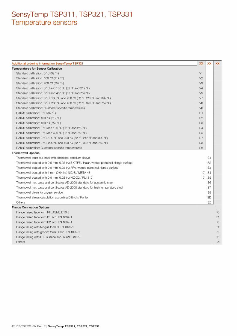
SensyTemp TSP311, TSP321, TSP331 Temperature sensors
42 DS/TSP3X1-EN Rev. E | SensyTemp TSP311, TSP321, TSP331
Additional ordering information SensyTemp TSP321 XX XX XX
Temperatures for Sensor Calibration
Standard calibration: 0 °C (32 °F) V1
Standard calibration: 100 °C (212 °F) V2
Standard calibration: 400 °C (752 °F) V3
Standard calibration: 0 °C and 100 °C (32 °F and 212 °F) V4
Standard calibration: 0 °C and 400 °C (32 °F and 752 °F) V5
Standard calibration: 0 °C, 100 °C and 200 °C (32 °F, 212 °F and 392 °F) V7
Standard calibration: 0 °C, 200 °C and 400 °C (32 °F, 392 °F and 752 °F) V8
Standard calibration: Customer specific temperatures V6
DAkkS calibration: 0 °C (32 °F) D1
DAkkS calibration: 100 °C (212 °F) D2
DAkkS calibration: 400 °C (752 °F) D3
DAkkS calibration: 0 °C and 100 °C (32 °F and 212 °F) D4
DAkkS calibration: 0 °C and 400 °C (32 °F and 752 °F) D5
DAkkS calibration: 0 °C, 100 °C and 200 °C (32 °F, 212 °F and 392 °F) D7
DAkkS calibration: 0 °C, 200 °C and 400 °C (32 °F, 392 °F and 752 °F) D8
DAkkS calibration: Customer specific temperatures D6
Thermowell Options
Thermowell stainless steel with additional tantalum sleeve S1
Thermowell coated with 0.5 mm (0.02 in.) E-CTFE / Halar, wetted parts incl. flange surface S2
Thermowell coated with 0.5 mm (0.02 in.) PFA, wetted parts incl. flange surface S3
Thermowell coated with 1 mm (0.04 in.) NiCrB / META 43 2) S4
Thermowell coated with 0.5 mm (0.02 in.) NiZrO2 / PL1312 2) S5
Thermowell incl. tests and certificates AD-2000 standard for austenitic steel S6
Thermowell incl. tests and certificates AD-2000 standard for high temperature steel S7
Thermowell clean for oxygen service S9
Thermowell stress calculation according Dittrich / Kohler SD
Others SZ
Flange Connection Options
Flange raised face form RF, ASME B16.5 F6
Flange raised face form B1 acc. EN 1092-1 F7
Flange raised face form B2 acc. EN 1092-1 F8
Flange facing with tongue form C EN 1092-1 F1
Flange facing with groove form D acc. EN 1092-1 F2
Flange facing with RTJ surface acc. ASME B16.5 F3
Others FZ

SensyTemp TSP311, TSP321, TSP331 | DS/TSP3X1-EN Rev. E 43
Additional ordering information SensyTemp TSP321 XX XX XX XX XX XX
Extension Tube Options
Mounting bracket N5
Measuring Inset: Option
Hot junction grounded J1
2 insets paired from 0 ... 100 °C (32 ... 212 °F), max. deviation 0.1 K J3
Improvement Sensor Accuracy to 0.5 Cl. A, 0 ... 100°C, U>100 mm J8
Improvement Sensor Accuracy to 0.5 Cl. A, 0 ... 400°C, U>250 mm J9
Measuring Inset: Transmitter Mounted
Transmitter mounted on inset, without ceramic block J2
Measuring Inset: Other Options
Others JZ
Connection Head Options
Second transmitter mounted in connection head (same type as first one) H1
Cover of connection head with chain attached to the lower part H8
Connetion head with capstan screw for sealing H9
Others HZ
Cable Entry Options
1 x M20 x 1.5, without cable gland U1
1 x 1/2 in. NPT, without cable gland U2
2 x M20 x 1.5, without cable gland U4
2 x 1/2 in. NPT, without cable gland U5
2x M20 x 1.5, with cable gland skintop, temperature range -40 bis +70 °C (-40 bis +158 °F) U7
1 x M20 x 1.5, with Ex-d cable gland UA
2 x M20 x 1.5, with Ex-d cable gland UC
Harting Han 7D plug and socket connection UG
Harting Han 8D (8U) plug and socket connection UH
M12 plug for PROFIBUS PA UJ
7/8 in. plug for FOUNDATION fieldbus UK
1 x 1/2 in. NPT-PE ADE 4F Capri Codec UF
1 x 1/2 in. NPT Capri Codec, with strain relief UL
1 x 1/2 in. NPT-PE ADE 4F + 1 x 1/2 in. NPT plug UP
Others UZ

SensyTemp TSP311, TSP321, TSP331 Temperature sensors
44 DS/TSP3X1-EN Rev. E | SensyTemp TSP311, TSP321, TSP331
Additional ordering information SensyTemp TSP321 XX XX XX XX XX
Display Type
LCD indicator type AS L1
Configurable LCD Indicator type A L2
Other Options
Earth screw internal PH
Name plate stanless steel PV
Each Thermometer single packed - Polyethylen PN
Documentation Language
German M1
English M5
Language package Western Europe / Scandinavia (Languages: DA, ES, FR, IT, NL, PT, FI, SV) MW
Language package Eastern Europe (Languages: EL, CS, ET, LV, LT, HU, HR, PL, SK, SL, RO, BG) ME
Additional TAG Plate
Stainless steel plate with TAG no. T1
Additional Identification Plate
Stainless steel plate with customer specific text T2
Adhesive label T3 1) According EN 60079-0 and EN 61241-0, the application in hybrid mixtures (concomitance of potentially explosive dust and gas) is currently not allowed. 2) Specify length from thermowell tip in mm.

SensyTemp TSP311, TSP321, TSP331 | DS/TSP3X1-EN Rev. E 45
Main ordering information SensyTemp TSP331 Base model
SensyTemp TSP331 Temperature Sensor, with drilled
thermowell, for heavy duty applications
TSP331 XX XX XX XXX XX XX XX XX XX XX XX XX XX
Explosion Protection / Approvals Continued see next page
Without Y0
Intrinsic Safety ATEX II 1 G Ex ia IIC T6 Ga or II 2 G Ex ib IIC T6 Gb or
II 1/2 G Ex ib IIC T6 Ga/Gb
A1
Dust ignition proof ATEX II 1 D IP6x A3
Dust ignition proof ATEX II 1 D IP6X T133 ... T400 and Intrinsic Safety
ATEX II 1 G Ex ia IIC T6 ... T1-Zone 0, 1, 2, 20, 21, 22
1)
A4
Flameproof enclosure ATEX II 1/2 G Ex d IIC T1 - T6 Ga/Gb A5
Non incendive ATEX II 3 G Ex nA IIC T1 - T6 Gc and
ATEX II 3 D Ex tc IIIB T133°C Dc
1)
B1
Dust ignition proof ATEX II 1 D IP6X T133 and Flameproof
enclosure ATEX II 1/2 G Ex d IIC T6 - Zone 1, 2, 20, 21, 22
1)
B5
Intrinsic Safety IECEx ia IIC T6 Ga H1
Intrinsic Safety IECEx ib IIC T6 Gb or IECEx ib IIC T6 Ga/Gb H2
Flameproof enclosure IECEx d IIC T1 - T6 Ga/Gb H5
Intrinsic Safety acc. NAMUR NE 24 and ATEX II 1 G Ex ia IIC T6 Ga N1
GOST Russia - metrological approval G1
GOST Russia - metrological approval and EAC-Ex, Ex i - Zone 0 P2
GOST Russia - metrological approval and EAC-Ex, Ex d P3
GOST Russia - metrological approval and EAC-Ex, dust ignition proof P4
GOST Kazakhstan - metrological approval G3
GOST Kazakhstan - metrological approval and EAC-Ex, Ex i - Zone 0 T2
GOST Kazakhstan - metrological approval and EAC-Ex, Ex d T3
GOST Kazakhstan - metrological approval and EAC-Ex, dust ignition proof T4
GOST Belarus - metrological approval M5
GOST Belarus - metrological approval and EAC-Ex, Ex i - Zone 0 U2
GOST Belarus - metrological approval and EAC-Ex, Ex d U3
GOST Belarus - metrological approval and EAC-Ex, dust ignition proof U4

SensyTemp TSP311, TSP321, TSP331 Temperature sensors
46 DS/TSP3X1-EN Rev. E | SensyTemp TSP311, TSP321, TSP331
Main ordering information SensyTemp TSP331 XX XX XXX XX XX XX XX XX XX XX XX XX
Wetted Thermowell Material Continued see next page
Stainless steel ASTM 316L (1.4404) S1
Stainless steel ASTM 316Ti (1.4571) S2
Heat-resistant stainless steel ASTM A182 F12 (1.7335) W1
Heat-resistant stainless steel ASTM A182 F22 (1.7380) W2
Heat-resistant stainless steel ASTM A182 F1 (1.5415) W3
Highly heat-resistant stainless steel ASTM A347 H (1.4961) W4
Highly heat-resistant stainless steel ASTM A446-1 (1.4749) H1
Heat resistant steel ASTM A446 (1.4762) H2
Heat resistant steel ASTM A314 (CrNi, 1.4841) H3
Duplex stainless steel (CrNi, 1.4462) S9
Stainless steel ASTM 904L (CrNi, 1.4539); (Uranus B6) S4
Ni-Alloy Hastelloy C-276 (2.4819) N1
Ni-Alloy Hastelloy C-4 (2.4610) N2
NiCu-Alloy Monel 400 (2.4360) N4
Ni-Alloy Incoloy 800 (1.4876) H4
Highly heat-resistant stainless steel , Ni-Alloy Inconel 600 (2.4816) N5
Highly heat-resistant stainless steel ASTM A182 F91 (1.4903) W5
Stainless steel ASTM 304 (CrNi, 1.4301) S5
Stainless steel ASTM 321 (CrNi, 1.4541) S6
Carbon steel ASTM A105 (1.0460) C1
Others Z9
Thermowell Type
Weld-in thermowell from bar stock material, diameter F2 = 24 mm (0.95 in.),
(DIN 43772, Form 4)
D1
Weld-in thermowell from bar stock material, diameter F2 = 18 mm (0.71 in.),
(DIN 43772, Form 4)
D2
Flanged thermowell from bar stock material, diameter F2 = 24 mm (0.95 in.),
(DIN 43772, Form 4F)
D3
Flanged thermowell from bar stock material, diameter F2 = 18 mm (0.71 in.),
(ABB-Form 4FS)
D4
Weld-in thermowell from bar stock material, diameter F2 = 26 mm (1.02 in.),
(DIN 43772, Form 4)
D5
Flanged thermowell from bar stock material, diameter F2 = 26 mm (1.02 in.),
(DIN 43772, Form 4F)
D6
Weld-in thermowell from bar stock material, (ABB, Form DR ) R1
Flanged thermowell from bar stock material, (ABB, Form DRF ) R2
Weld-in thermowell from bar stock material, ( ABB, Form RD ) R3
Flanged thermowell from bar stock material, ( ABB, Form RDF ) R4
Weld-in thermowell from bar stock material, (ABB, Form PW) P1
Flanged thermowell from bar stock material, (ABB, Form PF) P2
Screwed thermowell from bar stock material, tapered tip, (ABB, Form PS) P3
Screwed tubular thermowell from bar stock material, straight shaft (DIN 43772, Form 6) S1
Others Z9

SensyTemp TSP311, TSP321, TSP331 | DS/TSP3X1-EN Rev. E 47
Main ordering information SensyTemp TSP331 XXX XX XX XX XX XX XX XX XX XX
Process Connection Continued see next page
Without process connection Y00
Flange DN 25 PN 10 ... PN 40, EN 1092-1 F03
Flange DN 25 PN 63 ... PN100, EN 1092-1 F29
Flange DN 32 PN 16 … PN 40, EN 1092-1 F30
Flange DN 40 PN 10 ... PN 40, EN 1092-1 F04
Flange DN 40 PN 63 ... PN 100, EN 1092-1 F37
Flange DN 50 PN 6, EN 1092-1 F06
Flange DN 50 PN 10 ... PN 40, EN 1092-1 F05
Flange DN 50 PN 63, EN 1092-1 F33
Flange DN 50 PN 100, EN 1092-1 F34
Flange DN 80 PN 16, EN 1092-1 F35
Flange DN 100 PN 40, EN 1092-1 F36
Flange 1 in. 150 lbs, ASME B16.5 F07
Flange 1 in. 300 lbs, ASME B16.5 F08
Flange 1 in. 600 lbs, ASME B16.5 F09
Flange 1-1/2 in. 150 lbs, ASME B16.5 F11
Flange 1-1/2 in. 300 lbs, ASME B16.5 F12
Flange 1-1/2 in. 600 lbs, ASME B16.5 F13
Flange 1-1/2 in. 900 / 1500 lbs, ASME B16.5 F14
Flange 2 in. 150 lbs, ASME B16.5 F15
Flange 2 in. 300 lbs, ASME B16.5 F16
Flange 2 in. 600 lbs, ASME B16.5 F17
Flange 2 in. 900 / 1500 lbs, ASME B16.5 F18
Conical thread 1/2 in. NPT S04
Conical thread 3/4 in. NPT S05
Conical thread 1 in. NPT S06
Others Z99

SensyTemp TSP311, TSP321, TSP331 Temperature sensors
48 DS/TSP3X1-EN Rev. E | SensyTemp TSP311, TSP321, TSP331
Main ordering information SensyTemp TSP331 XX XX XX XX XX XX XX XX XX
Extension Tube Length Continued see next page
K = 150 mm (6 in.) K1
Customer specific length Z9
Thermowell Connection
Extension tube with Cylindrical thread G 1/2 A G1
Extension tube with Cylindrical thread G 3/4 A G2
Extension tube with Cylindrical thread G 3/8 A G3
Extension tube with Cylindrical thread M14 x 1,5 M1
Extension tube with Cylindrical thread M18 x 1,5 M2
Extension tube with Cylindrical thread M20 x 1,5 M3
Extension tube with Cylindrical thread M24 x 1,5 M4
Extension tube with conycal thread 1/2 in. NPT N1
Nipple / 1/2 in. NPT / 1/2 in. NPT N2
Nipple-Union / 1/2 in. NPT / Union 1/2 in. NPT N3
Nipple - Union - Nipple / 1/2 in. NPT / 1/2 in. NPT N4
Extension with Male nut, thread G 1/2 in. U6
Others Z9
Immersion Length
Without fixed immersion length Y0
U = 130 mm (5.2 in.) D1
U = 190 mm (7.5 in.) D2
U = 340 mm (13.4 in.) D3
U = 100 mm (4 in.) P1
U = 150 mm (6 in.) P2
U = 200 mm (8 in.) P3
U = 250 mm (10 in.) P4
U = 300 mm (12 in.) P5
U = 350 mm (14 in.) P6
Customer specific length Z9

SensyTemp TSP311, TSP321, TSP331 | DS/TSP3X1-EN Rev. E 49
Main ordering information SensyTemp TSP331 XX XX XX XX XX XX
Thermowell Length Continued see next
page L = 110 mm (4.4 in.), C = 65 mm (2.5 in.) D1
L = 115 mm (4.6 in.), C = 40 mm (1.5 in.) D2
L = 140 mm (5.6 in.), C = 65 mm (2.5 in.) D3
L = 200 mm (8 in.), C = 65 mm (2.5 in.) D4
L = 200 mm (8 in.), C = 125 mm (5 in.) D5
L = 260 mm (10.3 in.), C = 125 mm (5 in.) D6
L = 410 mm (16.2 in.), C = 275 mm (10.9 in.) D7
L = 146 mm (5.8 in.) R1
L = 175 mm (6.9 in.) R2
L = 265 mm (10.5 in.) R3
L = 415 mm (16.4 in.) R4
L = U + 65 mm (2.5 in.) - ABB-standard P1
Acc. customer specification D9
Customer specific length Z9
Measuring Inset Type
Without measuring inset Y0
RTD, TF, Basic application, measuring range -50 ... 400 °C (-58 ... 752 °F), 10 g S1
RTD, TF, Extended vibration resistance, measuring range -50 ... 400 °C (-58 ... 752 °F), 60 g S2
RTD, TF, Extended measuring range -196 ... 400 °C (-321 ... 752 °F), 10 g S3
RTD, TF, Extended vibration resistance, extendend measuring range -196 ... 400 °C (-321 ... 752 °F), 60 g S4
RTD, WW, Extended measuring range -196 ... 600 °C (-321 ... 1112 °F), 10 g D1
RTD, WW, Extended vibration resistance, extendend measuring range -196 ... 600 °C (-321 ... 1112 °F), 60 g D3
RTD, adjustable to German calibration regulations, sign of app. 000/308 - without calibration E1
RTD, custody preliminary, adjustable to German calibration regulations, sign of app. 000/308 - with calibration -10 °C
and +50 °C
E2
Thermocouple T1
Others Z9

SensyTemp TSP311, TSP321, TSP331 Temperature sensors
50 DS/TSP3X1-EN Rev. E | SensyTemp TSP311, TSP321, TSP331
Main ordering information SensyTemp TSP331 XX XX XX XX
Sensor Type and Wiring
Con
tinue
d se
e ne
xt p
age
Without measuring inset Y0
1 x Pt100, 2-wire P1
1 x Pt100, 3-wire P2
1 x Pt100, 4-wire P3
2 x Pt100, 2-wire P4
2 x Pt100, 3-wire P5
2 x Pt100, 4-wire P6
1 x Pt1000, 2-wire P8
1 x Pt1000, 3-wire P7
1 x Pt1000, 4-wire P9
1 x Type K (NiCr-NiAl) K1
2 x Type K (NiCr-NiAl) K2
3 x Type K (NiCr-NiAl) K3
1 x Type J (Fe-CuNi) J1
2 x Type J (Fe-CuNi) J2
1 x Type L (Fe-CuNi) L1
2 x Type L (Fe-CuNi) L2
1 x Type N (NiCrSi-NiSi) N1
2 x Type N (NiCrSi-NiSi) N2
1 x Type T (Cu-CuNi) T1
2 x Type T (Cu-CuNi) T2
1 x Type E (NiCr-CuNi) E1
2 x Type E (NiCr-CuNi) E2
1 x Type S (Pt10Rh-Pt) S1
2 x Type S (Pt10Rh-Pt) S2
Others Z9
Sensor Accuracy
Without measuring inset Y0
Accuracy Class B, IEC 60751 B2
Wire Wound, Double, Accuracy Class A, IEC 60751, Range 0 ... 250 °C (32 ... 482 °F) D2
Wire Wound, Accuracy Class A, IEC 60751, Range -100 ... 450 °C (-148 ... 842 °F) D1
Thin Film, Accuracy Class A, IEC 60751, Range -30 ... 300 °C (-22 ... 572 °F) S1
Thin Film, Accuracy Class AA, IEC 60751, Range 0 ... 100 °C (0 ... 212 °F) S3
Thin Film, Accuracy Class A extended according to IEC 60751, Range -196 ... 400 °C (-320,8 ... 752 °F) S6
Thin Film, Accuracy Class AA extended according to IEC 60751, Range -196 ... 400 °C (-320,8 ... 752 °F) S8
Thermocouple, Accuracy Class 2, IEC 60584 T2
Thermocouple, Accuracy Class 1, IEC 60584 T1
Thermocouple, Standard Accuracy ANSI MC96.1 T4
Thermocouple, Special Accuracy ANSI MC96.1 T3
Thermocouple, Accuracy according to DIN 43710 T5
Others Z9

SensyTemp TSP311, TSP321, TSP331 | DS/TSP3X1-EN Rev. E 51
Main ordering information SensyTemp TSP331 XX XX
Connection Head Type / Material
AGL / Aluminium, screwed cover L1
AGLH / Aluminium, high cover, screwed L2
AGLD / Aluminium, screwed cover with display L4
AGS / Stainless steel, screwed cover S1
AGSH / Stainless steel, high cover, screwed S2
AGSD / Stainless steel, screwed cover with display S4
Others Z9
Transmitter
Without transmitter, sensor with ceramic terminal block - spring loaded Y1
Without transmitter, sensor with flying leads and metal plate - spring loaded Y2
TTH300-HART, programmable, output signal 4 ... 20 mA, dual input H4
TTH300-HART, Ex version, programmable, output signal 4 ... 20 mA, dual input H5
TTH300-PA, programmable, output PROFIBUS PA, dual input P6
TTH300-PA, Ex version, programmable, output PROFIBUS PA, dual input P7
TTH300-FF, programmable, output FOUNDATION fieldbus H1, dual input F6
TTH300-FF, Ex version, programmable, output FOUNDATION fieldbus H1, dual input F7
TTH200-HART, programmable, output signal 4 ... 20 mA H6
TTH200-HART, Ex version, programmable, output signal 4 ... 20 mA H7

SensyTemp TSP311, TSP321, TSP331 Temperature sensors
52 DS/TSP3X1-EN Rev. E | SensyTemp TSP311, TSP321, TSP331
Additional ordering information SensyTemp TSP331 XX XX XX
Transmitter Measuring Range
Standard measuring range A0
Customer-specific measuring range AZ
Certificates
Declaration of compliance according EN 10204-2.1, with the order C4
Test report according EN 10204-2.2, material monitoring for wetted parts C1
Test report according EN 10204-2.2 for batch values, MIC-TC C5
Test report according EN 10204-2.2 for measuring of insulaionsresistance at ambient temperature CN
Inspection certificate according EN 10204-3.1, material monitoring for wetted parts C2
Inspection certificate according EN 10204-3.2, material monitoring for wetted parts C3
Inspection certificate according EN 10204-3.1, visual, dimensional and functional test C6
Inspection certificate according EN 10204-3.1, helium leakage test C7
Inspection certificate according EN 10204-3.1, dye penetration test C9
Inspection certificate according EN 10204-3.1, Positive Material Identification (PMI) CA
Inspection certificate according EN 10204-3.1, pressure test on thermowell CB
Inspection certificate according EN 10204-3.1, sensor tolerance CC
TÜV certificate for functional safety SIL2 IEC 61508 for sensor with integrated transmitter, HART CS
Inspection certificate according EN 10204-3.1, sensor calibration, single RTD CD
Inspection certificate according EN 10204-3.1, sensor calibration, double RTD CE
Inspection certificate according EN 10204-3.1, sensor calibration, single thermocouple CF
Inspection certificate according EN 10204-3.1, sensor calibration, double thermocouple CG
DAkkS sensor calibration, single RTD, calibration certificate per thermometer CH
DAkkS sensor calibration, double RTD, calibration certificate per thermometer CJ
DAkkS sensor calibration, single thermocouple, calibration certificate per thermometer CK
DAkkS sensor calibration, double thermocouple, calibration certificate per thermometer CL
Inspection certificate according EN 10204-3.1, x-ray- test for weldings CU
Inspection certificate according EN 10204-3.1, x-ray- test for bore concentricity CV
Inspection certificate according EN 10204-3.1, ultrasonic- test for bore concentricity CW
Others CZ
Number of Calibration Test Points
1 point P1
2 points P2
3 points P3
4 points P4
5 points P5

SensyTemp TSP311, TSP321, TSP331 | DS/TSP3X1-EN Rev. E 53
Additional ordering information SensyTemp TSP331 XX XX XX
Temperatures for Sensor Calibration
Standard calibration: 0 °C (32 °F) V1
Standard calibration: 100 °C (212 °F) V2
Standard calibration: 400 °C (752 °F) V3
Standard calibration: 0 °C and 100 °C (32 °F and 212 °F) V4
Standard calibration: 0 °C and 400 °C (32 °F and 752 °F) V5
Standard calibration: 0 °C, 100 °C and 200 °C (32 °F, 212 °F and 392 °F) V7
Standard calibration: 0 °C, 200 °C and 400 °C (32 °F, 392 °F and 752 °F) V8
Standard calibration: Customer specific temperatures V6
DAkkS calibration: 0 °C (32 °F) D1
DAkkS calibration: 100 °C (212 °F) D2
DAkkS calibration: 400 °C (752 °F) D3
DAkkS calibration: 0 °C and 100 °C (32 °F and 212 °F) D4
DAkkS calibration: 0 °C and 400 °C (32 °F and 752 °F) D5
DAkkS calibration: 0 °C, 100 °C and 200 °C (32 °F, 212 °F and 392 °F) D7
DAkkS calibration: 0 °C, 200 °C and 400 °C (32 °F, 392 °F and 752 °F) D8
DAkkS calibration: Customer specific temperatures D6
Thermowell Options
Thermowell stainless steel with additional tantalum sleeve S1
Thermowell coated with 0.5 mm (0.02 in.) E-CTFE / Halar, wetted parts incl. flange surface S2
Thermowell coated with 0.5 mm (0.02 in.) PFA, wetted parts incl. flange surface S3
Thermowell coated with 1 mm (0.04 in.) NiCrB / META 43 2) S4
Thermowell coated with 0.5 mm (0.02 in.) NiZrO2 / PL1312 2) S5
Thermowell incl. tests and certificates AD-2000 standard for austenitic steel S6
Thermowell incl. tests and certificates AD-2000 standard for high temperature steel S7
Thermowell incl. tests and certificates NACE MR 01-75 S8
Thermowell clean for oxygen service S9
Thermowell stress calculation according ASME 19.3-TW 2010 (Murdock) SM
Thermowell with plug, gasket and chain SP
Thermowell with plug and gasket SR
Others SZ
Flange Connection Options
Flange raised face form RF, ASME B16.5 F6
Flange raised face form B1 acc. EN 1092-1 F7
Flange raised face form B2 acc. EN 1092-1 F8
Flange facing with tongue form C EN 1092-1 F1
Flange facing with groove form D acc. EN 1092-1 F2
Flange facing with RTJ surface acc. ASME B16.5 F3
Flange full penetration welded F4
Others FZ

SensyTemp TSP311, TSP321, TSP331 Temperature sensors
54 DS/TSP3X1-EN Rev. E | SensyTemp TSP311, TSP321, TSP331
Additional ordering information SensyTemp TSP331 XX XX XX XX XX XX XX
Extension Tube Options
Extension tube welded with measuring inset, gas tight N3
Measuring Inset: Option
Hot junction grounded J1
2 insets paired from 0 ... 100 °C (32 ... 212 °F), max. deviation 0.1 K J3
Improvement Sensor Accuracy to 0.5 Cl. A, 0 ... 100°C, U>100 mm J8
Improvement Sensor Accuracy to 0.5 Cl. A, 0 ... 400°C, U>250 mm J9
Measuring Inset: Transmitter Mounted
Transmitter mounted on inset, without ceramic block J2
Measuring Inset: Other Options
Others JZ
Connection Head Options
Second transmitter mounted in connection head (same type as first one) H1
Cover of connection head with chain attached to the lower part H8
Connetion head with capstan screw for sealing H9
Others HZ
Cable Entry Options
1 x M20 x 1.5, without cable gland U1
1 x 1/2 in. NPT, without cable gland U2
2 x M20 x 1.5, without cable gland U4
2 x 1/2 in. NPT, without cable gland U5
2x M20 x 1.5, with cable gland skintop, temperature range -40 bis +70 °C (-40 bis +158 °F) U7
1 x M20 x 1.5, with Ex-d cable gland UA
2 x M20 x 1.5, with Ex-d cable gland UC
Harting Han 7D plug and socket connection UG
Harting Han 8D (8U) plug and socket connection UH
M12 plug for PROFIBUS PA UJ
7/8 in. plug for FOUNDATION fieldbus UK
1 x 1/2 in. NPT-PE ADE 4F Capri Codec UF
1 x 1/2 in. NPT Capri Codec, with strain relief UL
1 x 1/2 in. NPT-PE ADE 4F + 1 x 1/2 in. NPT plug UP
Others UZ
Display Type
LCD indicator type AS L1
Configurable LCD Indicator type A L2

SensyTemp TSP311, TSP321, TSP331 | DS/TSP3X1-EN Rev. E 55
Additional ordering information SensyTemp TSP331 XX XX XX XX
Other Options
Earth screw internal PH
Name plate stanless steel PV
Each Thermometer single packed - Polyethylen PN
Documentation Language
German M1
English M5
Language package Western Europe / Scandinavia (Languages: DA, ES, FR, IT, NL, PT, FI, SV) MW
Language package Eastern Europe (Languages: EL, CS, ET, LV, LT, HU, HR, PL, SK, SL, RO, BG) ME
Additional TAG Plate
Stainless steel plate with TAG no. T1
Additional Identification Plate
Stainless steel plate with customer specific text T2
Adhesive label T3 1) According EN 60079-0 and EN 61241-0, the application in hybrid mixtures (concomitance of potentially explosive dust and gas) is currently not allowed. 2) Specify length from thermowell tip in mm.
Change from one to two columns
Trademarks ® HART is a registered trademark of FieldComm Group, Austin, Texas,
USA
® PROFIBUS and PROFIBUS PA are registered trademarks of PROFIBUS
& PROFINET International (PI)
® FOUNDATION Fieldbus is a registered trademark of FieldComm Group,
Austin, Texas, USA
™ Hastelloy C-276 is a Cabot Corporation trademark
™ Hastelloy C-276 is a Haynes International trademark
™ Hastelloy C-4 is a Haynes International trademark
® Monel is a registered trademark of Special Metals Corporation Change from two to one column

— ABB Limited Measurement & Analytics Howard Road, St. Neots Cambridgeshire, PE19 8EU UK Tel: +44 (0)870 600 6122 Fax: +44 (0)1480 213 339 Email: [email protected] ABB Automation Products GmbH Measurement & Analytics Schillerstr. 72 32425 Minden Germany Tel: +49 571 830-0 Fax: +49 571 830-1806 abb.com/temperature
ABB Inc. Measurement & Analytics 125 E. County Line Road Warminster, PA 18974 USA Tel: +1 215 674 6000 Fax: +1 215 674 7183
DS/
TSP3
X1-
EN R
ev. E
0
1.20
19
— We reserve the right to make technical changes or modify the contents of this document without prior notice. With regard to purchase orders, the agreed particulars shall prevail. ABB does not accept any responsibility whatsoever for potential errors or possible lack of information in this document. We reserve all rights in this document and in the subject matter and illustrations contained therein. Any reproduction, disclosure to third parties or utilization of its contents – in whole or in parts – is forbidden without prior written consent of ABB. © ABB 2019 3KXT161002R1001
— ABB MEASUREMENT & ANALYTICS | DATA SHEET
SensyTemp TSP311, TSP321, TSP331 Temperature sensors