Embed Size (px)
Citation preview

Technical Manual
EM0314-00
Q YU TA L I
ENTM SE YG SA TN E
A M
M
R
Temperature AdvancedCalibrators
TA-25N / TA-35N / TA-50N
presys

EC Declaration of Conformity
We declare under our sole responsability that the CE marked products, are in conformity with the essential requirements of the following EC Directives when installed in accordance with the installation instructions contained in the product documentation:
Series TA-25N, TA-35N, TA-50N Description Dry-Block Temperature Calibrator
LVD Low Voltage Directive
2006/95/EC of the European Parliament and of the Council of 12 December 2006 on the harmonization of the laws of Member States relating to Electrical Equipment designed for use within certain voltage limits.
EN 61010-1:2011 Safety requirements for electrical equipment for measurement, control and laboratory
use
EN 61010-2:010 Safety requirements for electrical equipment for measurement, control and laboratory use - Part 2-010: Particular requirements for laboratory equipment for the heating of Materials.
EMC directive 2004/108/EC of the European Parliament and of the Council of 15 December 2004 on the approximation of the laws of the Member States relating to electromagnetic compatibility and repealing Directive 89/336/EEC
EN 61326-1:2003 Electrical equipment for measurement, control and laboratory use - EMC requirements
São Paulo, 8 September 2015
Vinicius José Gomes Nunes Antonio Rafael Sito Antunes CEO Engineering Manager
presys

The warranty conditions are available in our sites: www.presys.com.br/warranty
presys
PRESYS Instruments TA-25N / TA-35N / TA-50N
EM0314-01
Table of Contents
1 - Introduction ............................................................................................................... 1 1.1 - Technical Specifications ........................................................................................ 2
1.1.1 - Input Technical Specifications ........................................................................ 3 1.1.2 - Special Software Features.............................................................................. 4
1.2 - Order Code ........................................................................................................... 4 1.3 - Accessories .......................................................................................................... 5 1.4 - Parts Identification ................................................................................................ 7
2 - Calibrator Operation.................................................................................................. 8 2.1 - Calibrator Menu .................................................................................................... 9
2.1.1 - Probe Settings .............................................................................................. 11 2.1.2 - Input Settings ............................................................................................... 13 2.1.3 - Special Function ........................................................................................... 16 2.1.4 - Saving Current Configuration (Memory Manager) ........................................ 17
2.2 - Hart® Configuration ............................................................................................. 18 2.2.1 - HART® Connections ..................................................................................... 18 2.2.2 - Starting Communication ............................................................................... 19 2.2.3 - Adjusting the Measurement Range of a HART® Transmitter ........................ 19 2.2.4 - Adjusting the Measurement Range of a HART® Transmitter with Reference 20 2.2.5 - Checking / Adjusting HART® Transmitter mA Output .................................... 21
2.3 - Automatic Tasks ................................................................................................. 22 2.3.1 - Creating Tasks ............................................................................................. 22 2.3.2 - Performing Tasks ......................................................................................... 25 2.3.3 - Viewing Results ............................................................................................ 25
2.4 - Data-Logger ........................................................................................................ 27 2.5 - Videos ................................................................................................................. 29 2.6 - Settings ............................................................................................................... 29
2.6.1 - System ......................................................................................................... 29 2.6.2 - Network ........................................................................................................ 30 2.6.3 - Built-in Web Server ...................................................................................... 30
3 - Safety Instructions .................................................................................................. 32
4 - Recommendations as regards Accuracy of Measurements ................................ 32
5 - Calibration (Adjustment) ......................................................................................... 32 5.1 - Input Calibration .................................................................................................. 33 5.2 - Probe Calibration ................................................................................................ 34
6 - Maintenance ............................................................................................................. 35 6.1 - Instructions for Hardware Maintenance ............................................................... 35 6.2 - Instructions for Insert Jamming ........................................................................... 35 6.3 - Tiny Steel Balls, Recommendations of Use and Safety Instructions ................... 36
presys
PRESYS Instruments TA-25N / TA-35N / TA-50N
Page 1
1 - Introduction
TA-25N / TA-35N / TA-50N
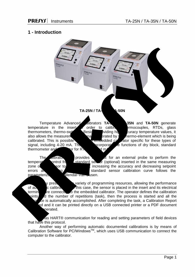
Temperature Advanced Calibrators TA-25N, TA-35N and TA-50N generate temperature in the insert in order to calibrate thermocouples, RTDs, glass thermometers, thermo-switches. Besides providing high accuracy temperature values, it also allows the measurement of signals generated by the thermo-element which is being calibrated. This is possible due to an embedded calibrator specific for these types of signal, including 4-20 mA. Thus, they incorporate the functions of dry block, standard thermometer and calibrator for RTD, TC and mA.
The calibrator also provides an input for an external probe to perform the temperature control from a standard sensor (optional) inserted in the same measuring zone of the sensor to be calibrated, increasing the accuracy and decreasing setpoint errors and loading effects. The standard sensor calibration curve follows the parameterization of Callendar-Van Dusen.
They present a wide variety of programming resources, allowing the performance of automatic calibrations. In this case, the sensor is placed in the insert and its electrical terminals are connected to the embedded calibrator. The operator defines the calibration points and the number of repetitions (task), then the process is started and all the sequence is automatically accomplished. After completing the task, a Calibration Report is issued and it can be printed directly on a USB connected printer or a PDF document can be generated. It has HART® communication for reading and setting parameters of field devices that have this protocol.
Another way of performing automatic documented calibrations is by means of Calibration Software for PC/WindowsTM, which uses USB communication to connect the computer to the calibrator.
presys
PRESYS Instruments TA-25N / TA-35N / TA-50N
Page 2
TA Calibrators have also many other features, such as:.
RTD input for 2, 3 and 4 wires. Table IEC 60751, JIS or Callendar-Van Dusen user-configurable. Engineering units configurable to °C, °F and K.
Present inputs for mA, thermocouples and thermo-switches. Use of internal standard thermometer. Accuracy to 0.1 ºC, stability of 0.02 ºC and resolution of 0.01ºC. Carry out completely automatic calibrations without the use of a computer. Built in Web Server, Ethernet communication and USB serial Communication. USB port for software/firmware upgrade. HART® Communication Protocol (optional) with internal resistance configurable,
transmitter power supply and latest DD as option. The electric signal calibrator is independent from the dry block function. Display indication when the temperature reaches the desired value. 5.7 inches touchscreen display that eases the operation and configuration of the
calibrator. Thermo-element reading scaled to ITS-90 or IPTS-68. Internal regulated 24 Vdc power supply for 2-wire transmitters. Independent circuit for over-temperature protection and safety. Insert to choose, soft carrying case, handles and test leads included. If the insert is
not specified, it will be provided the insert type IN06.
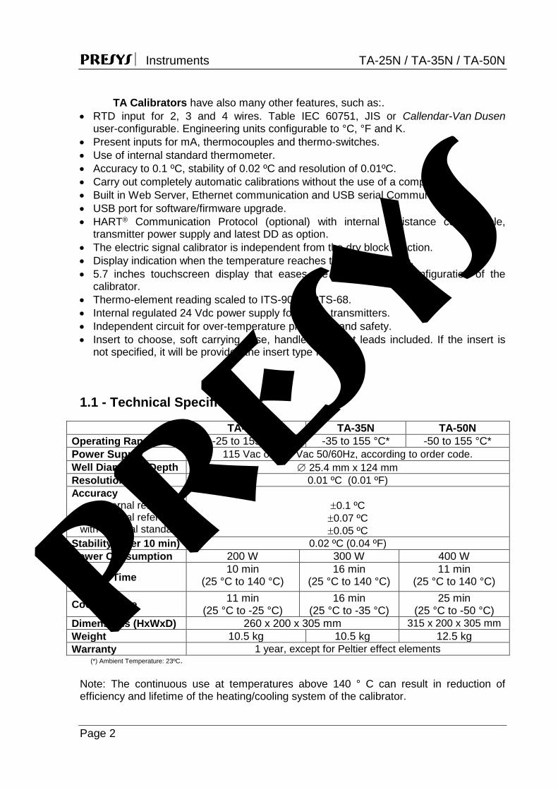
1.1 - Technical Specifications
TA-25N TA-35N TA-50N Operating Range -25 to 155 °C* -35 to 155 °C* -50 to 155 °C* Power Supply 115 Vac or 230 Vac 50/60Hz, according to order code. Well Diameter / Depth 25.4 mm x 124 mm Resolution 0.01 ºC (0.01 ºF) Accuracy
internal reference with external reference
with external standard
0.1 ºC 0.07 ºC 0.05 ºC
Stability (after 10 min) 0.02 ºC (0.04 ºF) Power Consumption 200 W 300 W 400 W
Heating Time 10 min
(25 °C to 140 °C) 16 min
(25 °C to 140 °C) 11 min
(25 °C to 140 °C)
Cooling Time 11 min (25 °C to -25 °C)
16 min (25 °C to -35 °C)
25 min (25 °C to -50 °C)
Dimensions (HxWxD) 260 x 200 x 305 mm 315 x 200 x 305 mm Weight 10.5 kg 10.5 kg 12.5 kg Warranty 1 year, except for Peltier effect elements
(*) Ambient Temperature: 23ºC. Note: The continuous use at temperatures above 140 ° C can result in reduction of efficiency and lifetime of the heating/cooling system of the calibrator.
presys
PRESYS Instruments TA-25N / TA-35N / TA-50N
Page 3
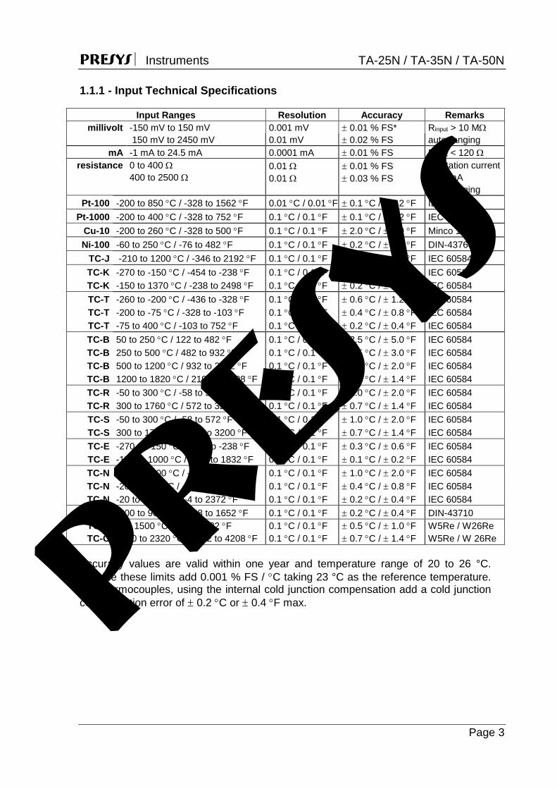
1.1.1 - Input Technical Specifications
Input Ranges Resolution Accuracy Remarks millivolt -150 mV to 150 mV 0.001 mV 0.01 % FS* Rinput > 10 M
150 mV to 2450 mV 0.01 mV 0.02 % FS auto-ranging mA -1 mA to 24.5 mA 0.0001 mA 0.01 % FS Rinput < 120
resistance 0 to 400 400 to 2500
0.01 0.01
0.01 % FS 0.03 % FS
Excitation current 0.85 mA auto-ranging
Pt-100 -200 to 850 C / -328 to 1562 F 0.01 C / 0.01 F 0.1 C / 0.2 F IEC 60751 Pt-1000 -200 to 400 C / -328 to 752 F 0.1 C / 0.1 F 0.1 C / 0.2 F IEC 60751
Cu-10 -200 to 260 C / -328 to 500 F 0.1 C / 0.1 F 2.0 C / 4.0 F Minco 16-9 Ni-100 -60 to 250 C / -76 to 482 F 0.1 C / 0.1 F 0.2 C / 0.4 F DIN-43760
TC-J -210 to 1200 C / -346 to 2192 F 0.1 C / 0.1 F 0.2 C / 0.4 F IEC 60584 TC-K -270 to -150 C / -454 to -238 F 0.1 C / 0.1 F 0.5 C / 1.0 F IEC 60584 TC-K -150 to 1370 C / -238 to 2498 F 0.1 C / 0.1 F 0.2 C / 0.4 F IEC 60584 TC-T -260 to -200 C / -436 to -328 F 0.1 C / 0.1 F 0.6 C / 1.2 F IEC 60584 TC-T -200 to -75 C / -328 to -103 F 0.1 C / 0.1 F 0.4 C / 0.8 F IEC 60584 TC-T -75 to 400 C / -103 to 752 F 0.1 C / 0.1 F 0.2 C / 0.4 F IEC 60584 TC-B 50 to 250 C / 122 to 482 F 0.1 C / 0.1 F 2.5 C / 5.0 F IEC 60584 TC-B 250 to 500 C / 482 to 932 F 0.1 C / 0.1 F 1.5 C / 3.0 F IEC 60584 TC-B 500 to 1200 C / 932 to 2192 F 0.1 C / 0.1 F 1.0 C / 2.0 F IEC 60584 TC-B 1200 to 1820 C / 2192 to 3308 F 0.1 C / 0.1 F 0.7 C / 1.4 F IEC 60584 TC-R -50 to 300 C / -58 to 572 F 0.1 C / 0.1 F 1.0 C / 2.0 F IEC 60584 TC-R 300 to 1760 C / 572 to 3200 F 0.1 C / 0.1 F 0.7 C / 1.4 F IEC 60584 TC-S -50 to 300 C / -58 to 572 F 0.1 C / 0.1 F 1.0 C / 2.0 F IEC 60584 TC-S 300 to 1760 C / 572 to 3200 F 0.1 C / 0.1 F 0.7 C / 1.4 F IEC 60584 TC-E -270 to -150 C / -454 to -238 F 0.1 C / 0.1 F 0.3 C / 0.6 F IEC 60584 TC-E -150 to 1000 C / -238 to 1832 F 0.1 C / 0.1 F 0.1 C / 0.2 F IEC 60584 TC-N -260 to -200 C / -436 to -328 F 0.1 C / 0.1 F 1.0 C / 2.0 F IEC 60584 TC-N -200 to -20 C / -328 to -4 F 0.1 C / 0.1 F 0.4 C / 0.8 F IEC 60584 TC-N -20 to 1300 C / -4 to 2372 F 0.1 C / 0.1 F 0.2 C / 0.4 F IEC 60584 TC-L -200 to 900 C / -328 to 1652 F 0.1 C / 0.1 F 0.2 C / 0.4 F DIN-43710 TC-C 0 to 1500 C / 32 to 2732 F 0.1 C / 0.1 F 0.5 C / 1.0 F W5Re / W26Re TC-C 1500 to 2320 C / 2732 to 4208 F 0.1 C / 0.1 F 0.7 C / 1.4 F W5Re / W 26Re
Accuracy values are valid within one year and temperature range of 20 to 26 °C. Outside these limits add 0.001 % FS / C taking 23 °C as the reference temperature. For thermocouples, using the internal cold junction compensation add a cold junction compensation error of 0.2 C or 0.4 F max. pr
esys
PRESYS Instruments TA-25N / TA-35N / TA-50N
Page 4
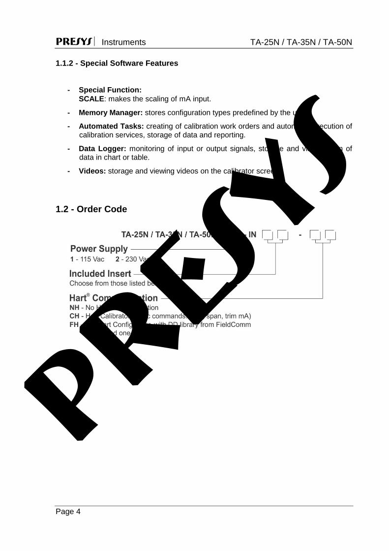
1.1.2 - Special Software Features
- Special Function:
SCALE: makes the scaling of mA input.
- Memory Manager: stores configuration types predefined by the user.
- Automated Tasks: creating of calibration work orders and automatic execution of calibration services, storage of data and reporting.
- Data Logger: monitoring of input or output signals, storage and visualization of data in chart or table.
- Videos: storage and viewing videos on the calibrator screen. 1.2 - Order Code
presys

PRESYS Instruments TA-25N / TA-35N / TA-50N
Page 5
1.3 - Accessories
Dry Block Insert:
Inserts Holes Order Code IN01 1 x 3/4" 06.04.0011-00 IN02 1 x 1/2" 06.04.0012-00 IN03 1 x 6.0mm and 3 x 1/4" 06.04.0013-00 IN04 3 x 6.0mm and 1 x 1/4" 06.04.0014-00 IN05 4 x 6.0mm 06.04.0015-00 IN06 2 x 6.0mm and 2 x 1/4" 06.04.0016-00 IN07 1 x 6.0mm, 1 x 8.0mm and 1 x 3/8" 06.04.0017-00 IN08 1 x 6.0mm, 1 x 3.0mm and 2 x 1/4" 06.04.0018-00 IN09 Without hole, to be drilled by the client 06.04.0019-00 IN10 Others, under ordering 06.04.0020-00 INCL Cup-like insert (for use with tiny steel balls) 06.04.0086-00 IN1P 1 x 3mm, 1 x 6mm, 1 x 8mm, 1 x 1/4" 06.04.0121-00 IN1A 1 x 1/8", 1 x 3/16", 2 x 1/4", 1 x 3/8" 06.04.0122-00 IN1E 1 x 4mm, 1 x 6mm, 2 x 8mm, 1 x 10mm, 1 x 1/4" 06.04.0123-00
Note: When asked, the calibration certificate will be provided for the first insert ordered.
Fig. 01 - Inserts
presys

PRESYS Instruments TA-25N / TA-35N / TA-50N
Page 6
Accessories:
Description Order Code Soft Carrying Case for TA-25N/TA-35N models 06.01.1031-00 Soft Carrying Case for TA-50N model 06.01.1032-00 Insert Extractor 02.06.0085-20 Tiny Steel Balls Flask 03.03.0144-21 Lead Cable Kit 06.07.0018-00
Power Cable Type J – Brazil
01.14.0008-21
Power Cable Type B – US
01.14.0100-21
Power Cable Type F – Europe Universal
01.14.0089-21
Power Cable Type J – UK
01.14.0117-21
Accessories included:
- 01 x Soft Carrying Case, - 01 x Insert Extractor, - 01 x Insert (according to order code); - 01 x Cup-like insert, - 01 x Tiny Steel Balls Flask. - 01 x Power cable, - 01 x Lead Cable Kit, - 01 x Technical Manual
Notes: * HART® is a FieldComm Group trademark. pr
esys
PRESYS Instruments TA-25N / TA-35N / TA-50N
Page 7
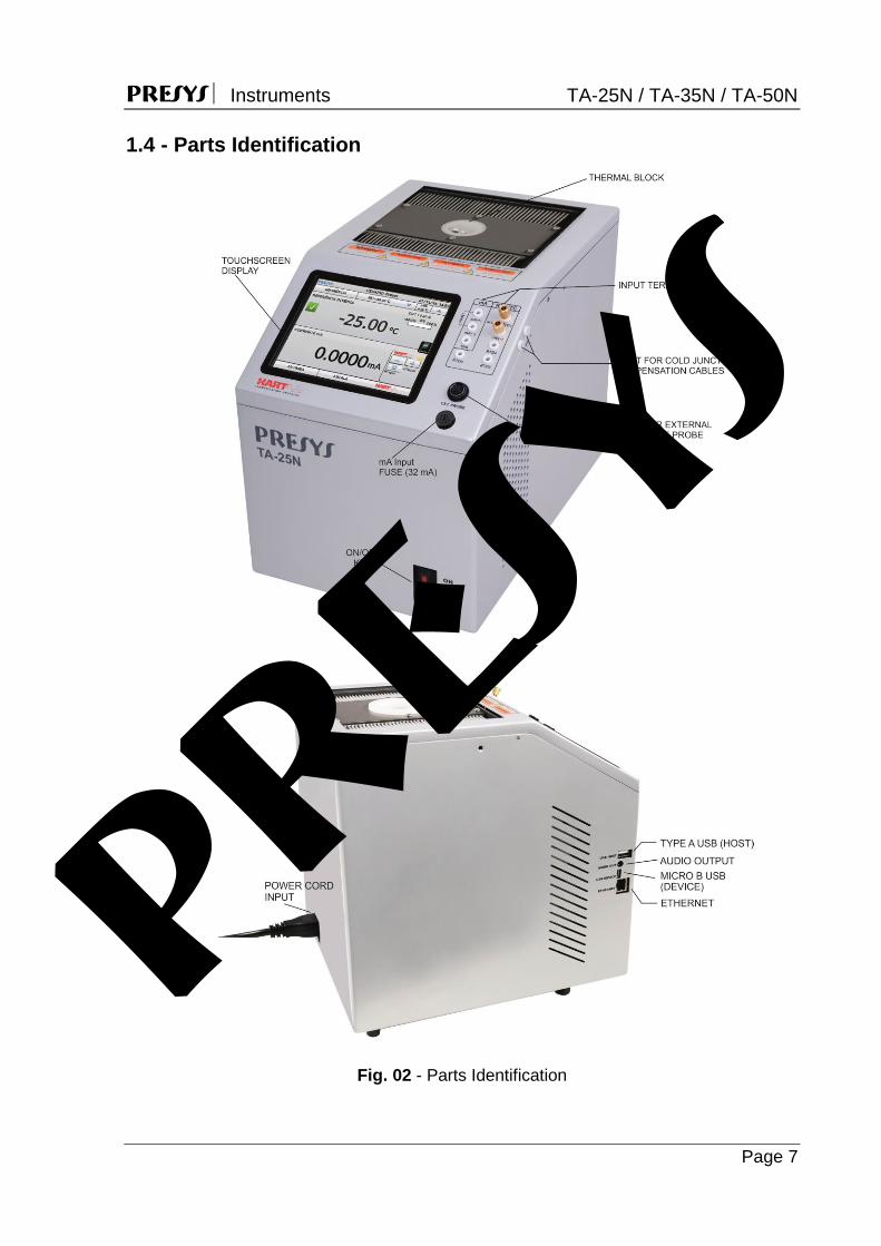
1.4 - Parts Identification
Fig. 02 - Parts Identification
presys
PRESYS Instruments TA-25N / TA-35N / TA-50N
Page 8
2 - Calibrator Operation
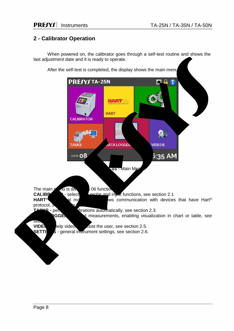
When powered on, the calibrator goes through a self-test routine and shows the
last adjustment date and it is ready to operate.
After the self-test is completed, the display shows the main menu:
Fig. 03 - Main Menu
The main menu is divided in 06 functions: CALIBRATOR - selects the probe and input functions, see section 2.1 HART® - optional module that allows communication with devices that have Hart® protocol, see section 2.2. TASKS - performs calibrations automatically, see section 2.3. DATA LOGGER - record measurements, enabling visualization in chart or table, see section 2.4. VIDEOS - help videos to assist the user, see section 2.5. SETTINGS - general instrument settings, see section 2.6. pr
esys
PRESYS Instruments TA-25N / TA-35N / TA-50N
Page 9
2.1 - Calibrator Menu
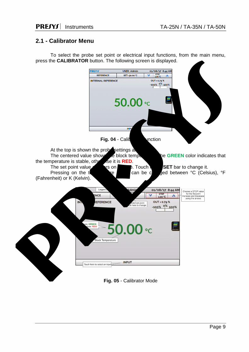
To select the probe set point or electrical input functions, from the main menu, press the CALIBRATOR button. The following screen is displayed.
Fig. 04 - Calibrator Function
At the top is shown the probe settings and values. The centered value shows the block temperature. The GREEN color indicates that
the temperature is stable, otherwise it is RED. The set point value appears on the top. Touch in the SET bar to change it. Pressing on the temperature unit it can be changed between °C (Celsius), °F
(Fahrenheit) or K (Kelvin).
Fig. 05 - Calibrator Mode presys
PRESYS Instruments TA-25N / TA-35N / TA-50N
Page 10
In the STEP function, a step value can be configured, and the steps can be changed through the up and down arrows.
In REFERENCE menu, you can configure the type of probe reference (see section 2.1.1 – Probe Reference). The chosen reference appears just below the REFERENCE button.
At the bottom, an input can be configured. When the input is selected, the screen will split automatically. To select an input, just touch the INPUT bar (see section 2.1.2 - MENU INPUT).
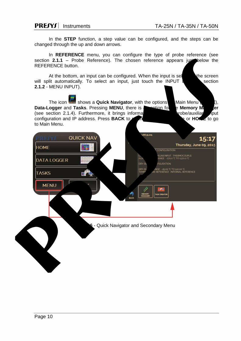
The icon shows a Quick Navigator, with the options for Main Menu (HOME), Data-Logger and Tasks. Pressing MENU, there is an option for the Memory Manager (see section 2.1.4). Furthermore, it brings information about the probe/auxiliary input configuration and IP address. Press BACK to return to Calibrator Mode or HOME to go to Main Menu.
Fig. 06 - Quick Navigator and Secondary Menu
presys
PRESYS Instruments TA-25N / TA-35N / TA-50N
Page 11
2.1.1 - Probe Settings
There are two different references to control the thermal block: Internal
Reference and External Reference. The Internal Reference is a sensor built into the block. The External Reference is an option for more accurate measurements. The
control reference comes from a Standard Sensor placed inside the insert, among the DUT (devices under test). This Standard Sensor, with Callendar-Van Dusen parameters, eliminates adjustment errors and block loading effects.
It can be used both in control and measurement mode. When used in measurement mode, the probe indication is displayed on the screen and the control is made by the internal probe.
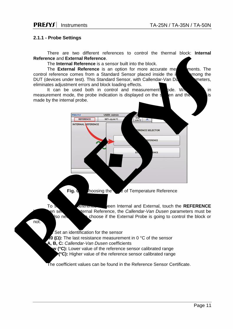
Fig. 07 - Choosing the Type of Temperature Reference
To select the Reference between Internal and External, touch the REFERENCE
bar. When selecting External Reference, the Callendar-Van Dusen parameters must be set. It is also necessary to choose if the External Probe is going to control the block or not.
ID: Set an identification for the sensor R0 (): The last resistance measurement in 0 °C of the sensor A, B, C: Callendar-Van Dusen coefficients Low (°C): Lower value of the reference sensor calibrated range High (°C): Higher value of the reference sensor calibrated range The coefficient values can be found in the Reference Sensor Certificate. pr
esys

PRESYS Instruments TA-25N / TA-35N / TA-50N
Page 12
Fig. 08 - Adding a new Reference Sensor
After filling the blanks, click on SAVE button and confirm. The new sensor is now available to be chosen in the list. To edit data from a sensor, select it and press MANAGER button. To remove a sensor, select it and press REMOVE
Fig. 09 - Connecting the Standard Sensor for the External Reference
Note: the values corresponding to controlled temperatures appear in GREEN / RED. Values that show only the sensor indication appear in BLACK. pr
esys
PRESYS Instruments TA-25N / TA-35N / TA-50N
Page 13
2.1.2 - Input Settings
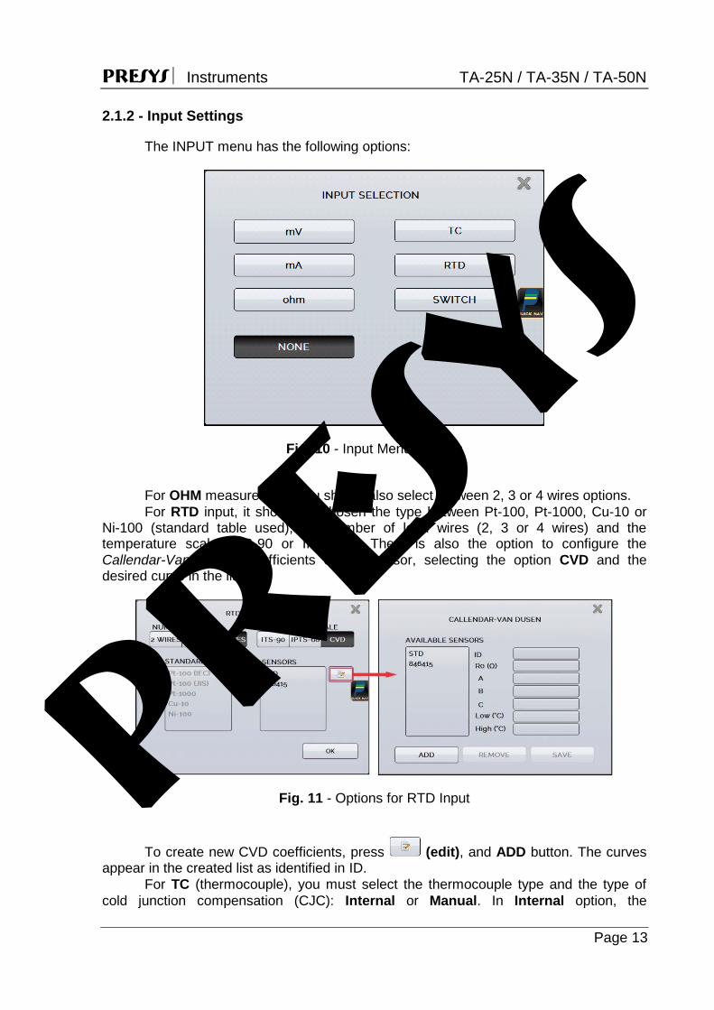
The INPUT menu has the following options:
Fig. 10 - Input Menu Options
For OHM measurement, you should also select between 2, 3 or 4 wires options. For RTD input, it should be chosen the type between Pt-100, Pt-1000, Cu-10 or
Ni-100 (standard table used), the number of lead wires (2, 3 or 4 wires) and the temperature scale (ITS-90 or IPTS-68). There is also the option to configure the Callendar-Van Dusen coefficients of the sensor, selecting the option CVD and the desired curve in the list.
Fig. 11 - Options for RTD Input
To create new CVD coefficients, press (edit), and ADD button. The curves
appear in the created list as identified in ID. For TC (thermocouple), you must select the thermocouple type and the type of
cold junction compensation (CJC): Internal or Manual. In Internal option, the
presys

PRESYS Instruments TA-25N / TA-35N / TA-50N
Page 14
compensation is done internally; In Manual you must provide the value of the temperature of the cold junction to the calibrator.
The option SWITCH has two ways to be used. For the option MANUAL, the input works as a continuity measurement between RTD2 and RTD4 terminals. When there is continuity, the input shows CLOSED, if not, indicates OPEN. The input also records the temperature value of the block at the time of contact opening / closure.
Using the option THERMOSWITCH TEST, the calibrator performs cycles registering the thermoswitch opening and closure interactively, in order to find the setpoint temperature of the thermoswitch and its respective hysteresis. In Setpoint Hi set a temperature above the opening of the thermoswitch contact. In Setpoint Lo, use a value below the setpoint discounted hysteresis. E.g.: To test a thermostat of 50 °C setpoint and 5 °C hysteresis, Setpoint HI can be set to 55 °C and Setpoint LO to 45 °C.
Fig. 12 - Switch Auto Test Parameters
It is important that the number of cycles be at least 3. By selecting this amount
you can check the repeatability of the thermoswitch. For the accuracy, when choosing higher accuracy levels, the temperature ramp times will be higher too. If a Report is needed for this test, use the TASK function.
The NONE option turns off the input function. When the input sensor breaking occur (RTD, resistance or probe) the display will
show the burn-out warning identified by question marks illustrated below:
Fig. 13 - Burn-out Warning
If an out of range signal is detected, a message of UNDER or OVER range appears.
presys

PRESYS Instruments TA-25N / TA-35N / TA-50N
Page 15
2.1.2.1 - Input Connections Diagrams
Fig. 14 - Input Connections
presys

PRESYS Instruments TA-25N / TA-35N / TA-50N
Page 16
2.1.3 - Special Function
SCALE: For the current input, it is possible to use the scale function:
Fig. 15 - Option for mA Input: SCALE
It establishes a linear relationship between the mA input signal and what is shown
at the display, according to the graphic below:
Fig. 16 - SCALE Function (LINEAR)
The scaled indication at the display (#) may represent any engineering unit, such as: °C, %, etc.
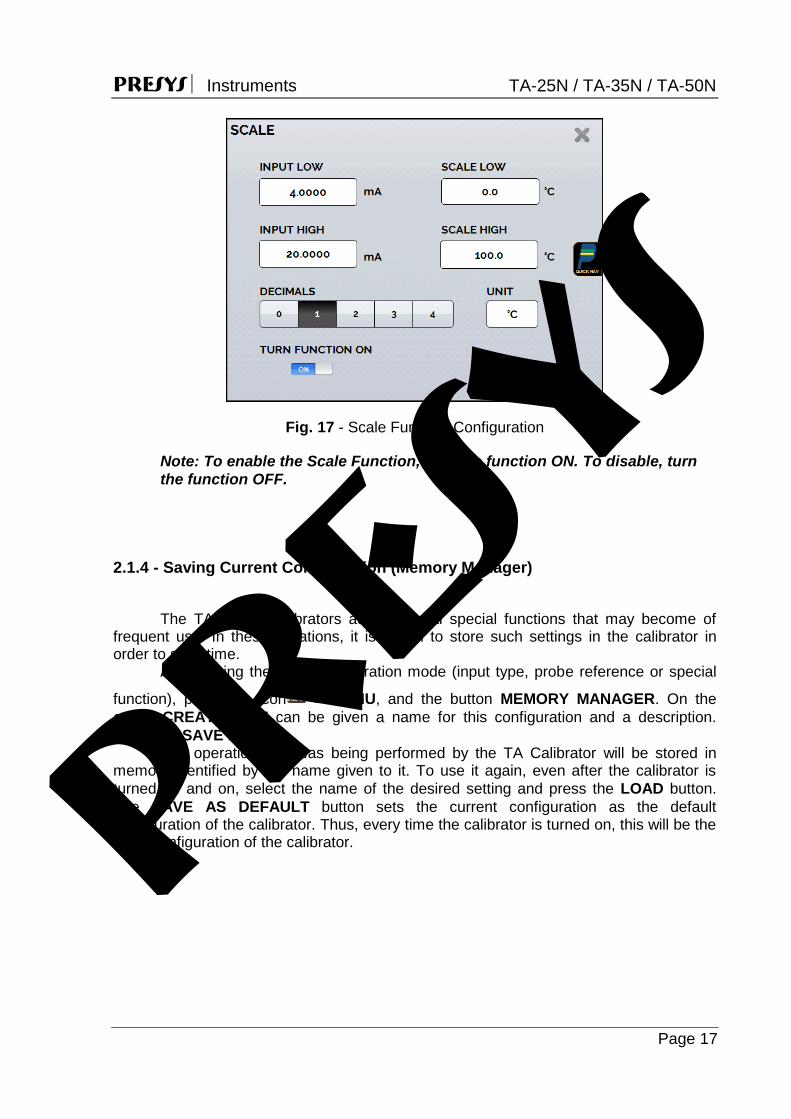
The number of decimals, up to 4, shown at the display may be configured. The value for Input High must be necessarily higher than Input Low. On the
other hand, Scale High and Scale Low may have any relationship between themselves: higher than, lower than or equal to, and they may have a signal before them. Thus direct or reverse relationships may be established. pr
esys
PRESYS Instruments TA-25N / TA-35N / TA-50N
Page 17
Fig. 17 - Scale Function Configuration
Note: To enable the Scale Function, turn the function ON. To disable, turn
the function OFF.
2.1.4 - Saving Current Configuration (Memory Manager)
The TA Series calibrators admit several special functions that may become of frequent use. In these situations, it is useful to store such settings in the calibrator in order to save time. After setting the desired calibration mode (input type, probe reference or special
function), press the icon > MENU, and the button MEMORY MANAGER. On the option CREATE NEW can be given a name for this configuration and a description. Press the SAVE button. The operation that was being performed by the TA Calibrator will be stored in memory identified by the name given to it. To use it again, even after the calibrator is turned off and on, select the name of the desired setting and press the LOAD button. The SAVE AS DEFAULT button sets the current configuration as the default configuration of the calibrator. Thus, every time the calibrator is turned on, this will be the initial configuration of the calibrator.
pr
esys
PRESYS Instruments TA-25N / TA-35N / TA-50N
Page 18
2.2 - Hart® Configuration The TA Series Calibrators can be used to read and set parameters of devices that
have HART® Communication Protocol. The HART® Protocol allows digital communication between master (in this case, the TA Calibrator) and the slave (field instrument) superimposed on the 4-20 mA analog signal. To access this function from the main menu, select the HART® option.
The HART® Communication of TA Calibrators is an optional module. The calibrator has three versions: NH (without HART® Communication), CH (HART® Calibrator) and FH (Full-HART® configurator with DD library).
The CH option has basic and universal commands for HART® communication (zero, span, trim mA etc.) that allows you to adjust the range of the instrument, monitoring the primary variable, current adjustment etc. The FH option, in addition to basic and universal commands, is provided with the DD library (Device Description) from FieldComm Group and allows the setting of specific parameters of each instrument.
The following description is valid for CH and FH options.
2.2.1 - HART® Connections
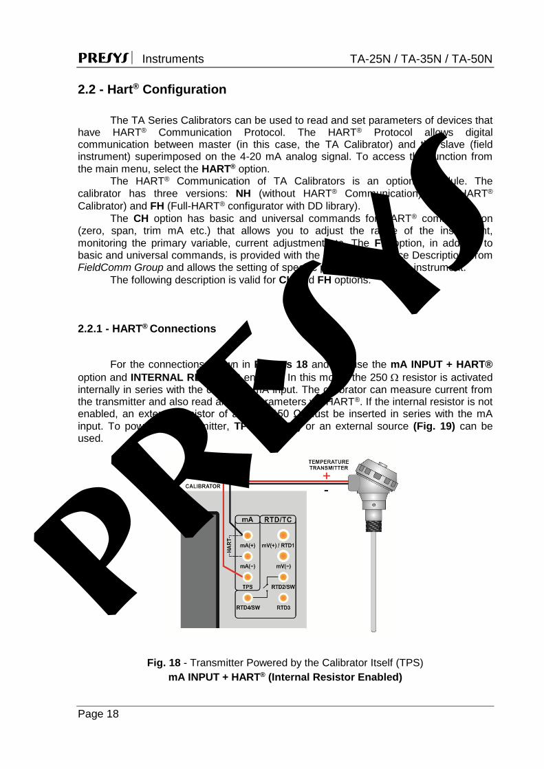
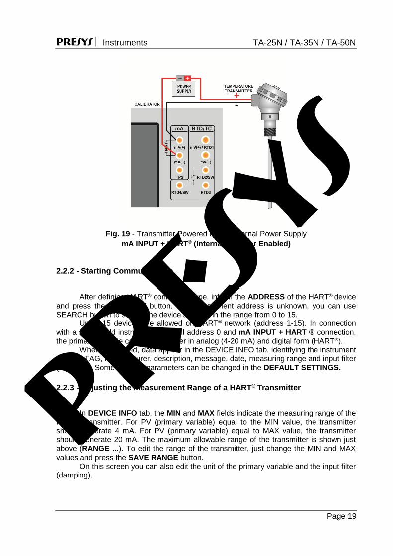
For the connections shown in Figures 18 and 19, use the mA INPUT + HART®
option and INTERNAL RESISTOR enabled. In this mode, the 250 resistor is activated internally in series with the calibrator mA input. The calibrator can measure current from the transmitter and also read and set parameters via HART®. If the internal resistor is not enabled, an external resistor of at least 150 Ω must be inserted in series with the mA input. To power the transmitter, TPS (Fig. 18) or an external source (Fig. 19) can be used.
Fig. 18 - Transmitter Powered by the Calibrator Itself (TPS) mA INPUT + HART® (Internal Resistor Enabled)
presys
PRESYS Instruments TA-25N / TA-35N / TA-50N
Page 19
Fig. 19 - Transmitter Powered by an External Power Supply
mA INPUT + HART® (Internal Resistor Enabled)
2.2.2 - Starting Communication
After defining HART® connection type, inform the ADDRESS of the HART® device
and press the CONNECT button. If the instrument address is unknown, you can use SEARCH button to search the device address in the range from 0 to 15.
Up to 15 devices are allowed on HART® network (address 1-15). In connection with a single field instrument with poll address 0 and mA INPUT + HART ® connection, the primary variable can be read either in analog (4-20 mA) and digital form (HART®).
When connected, data appear in the DEVICE INFO tab, identifying the instrument such as TAG, manufacturer, description, message, date, measuring range and input filter (damping). Some of these parameters can be changed in the DEFAULT SETTINGS. 2.2.3 - Adjusting the Measurement Range of a HART® Transmitter
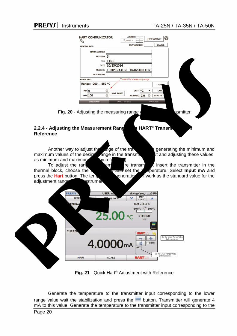
In DEVICE INFO tab, the MIN and MAX fields indicate the measuring range of the
HART® transmitter. For PV (primary variable) equal to the MIN value, the transmitter should generate 4 mA. For PV (primary variable) equal to MAX value, the transmitter should generate 20 mA. The maximum allowable range of the transmitter is shown just above (RANGE ...). To edit the range of the transmitter, just change the MIN and MAX values and press the SAVE RANGE button.
On this screen you can also edit the unit of the primary variable and the input filter (damping).
presys
PRESYS Instruments TA-25N / TA-35N / TA-50N
Page 20
Fig. 20 - Adjusting the measuring range of the HART® transmitter
2.2.4 - Adjusting the Measurement Range of a HART® Transmitter with Reference
Another way to adjust the range of the transmitter is generating the minimum and maximum values of the desired range in the transmitter input and adjusting these values as minimum and maximum (set by reference). To adjust the range of a temperature transmitter, insert the transmitter in the thermal block, choose the Reference, and set the temperature. Select Input mA and press the Hart button. The temperature generation will work as the standard value for the adjustment range of the instrument.
Fig. 21 - Quick Hart® Adjustment with Reference
Generate the temperature to the transmitter input corresponding to the lower range value wait the stabilization and press the button. Transmitter will generate 4 mA to this value. Generate the temperature to the transmitter input corresponding to the
presys
PRESYS Instruments TA-25N / TA-35N / TA-50N
Page 21
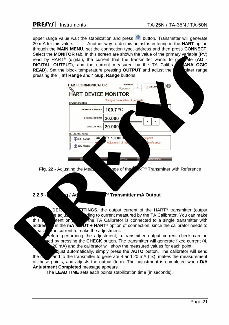
upper range value wait the stabilization and press button. Transmitter will generate 20 mA for this value. Another way to do this adjust is entering in the HART option through the MAIN MENU, set the connection type, address and then press CONNECT. Select the MONITOR tab. In this screen are shown the value of the primary variable (PV) read by HART® (digital), the current that the transmitter wants to generate (AO - DIGITAL OUTPUT), and the current measured by the TA Calibrator (ANALOGIC READ). Set the block temperature pressing OUTPUT and adjust the transmitter range pressing the ↓ Inf Range and ↑ Sup. Range buttons.
Fig. 22 - Adjusting the Measuring Range of the HART® Transmitter with Reference
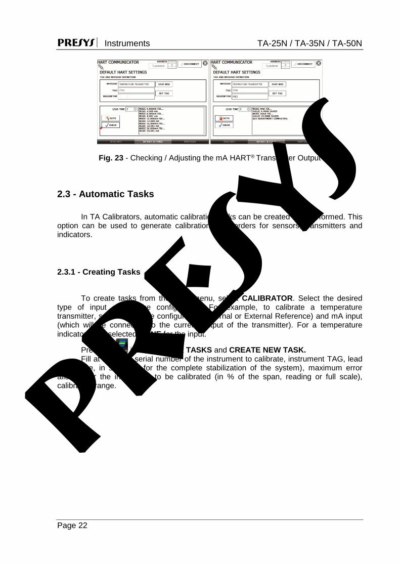
2.2.5 - Checking / Adjusting HART® Transmitter mA Output
In DEFAULT SETTINGS, the output current of the HART® transmitter (output
trim) can be adjusted according to current measured by the TA Calibrator. You can make this adjustment only when the TA Calibrator is connected to a single transmitter with address 0, in the mA INPUT + HART® option of connection, since the calibrator needs to measure the current to make the adjustment.
Before performing the adjustment, a transmitter output current check can be performed by pressing the CHECK button. The transmitter will generate fixed current (4, 8, 12, 16, 20 mA) and the calibrator will show the measured values for each point.
To adjust automatically, simply press the AUTO button. The calibrator will send the command to the transmitter to generate 4 and 20 mA (fix), makes the measurement of these points, and adjusts the output (trim). The adjustment is completed when D/A Adjustment Completed message appears.
The LEAD TIME sets each points stabilization time (in seconds).
presys
PRESYS Instruments TA-25N / TA-35N / TA-50N
Page 22
Fig. 23 - Checking / Adjusting the mA HART® Transmitter Output
2.3 - Automatic Tasks In TA Calibrators, automatic calibration tasks can be created and performed. This
option can be used to generate calibration work orders for sensors, transmitters and indicators.
2.3.1 - Creating Tasks
To create tasks from the main menu, select CALIBRATOR. Select the desired
type of input and probe configuration. For example, to calibrate a temperature transmitter, select the probe configuration (Internal or External Reference) and mA input (which will be connected to the current output of the transmitter). For a temperature indicator, e.g., selected NONE for the input.
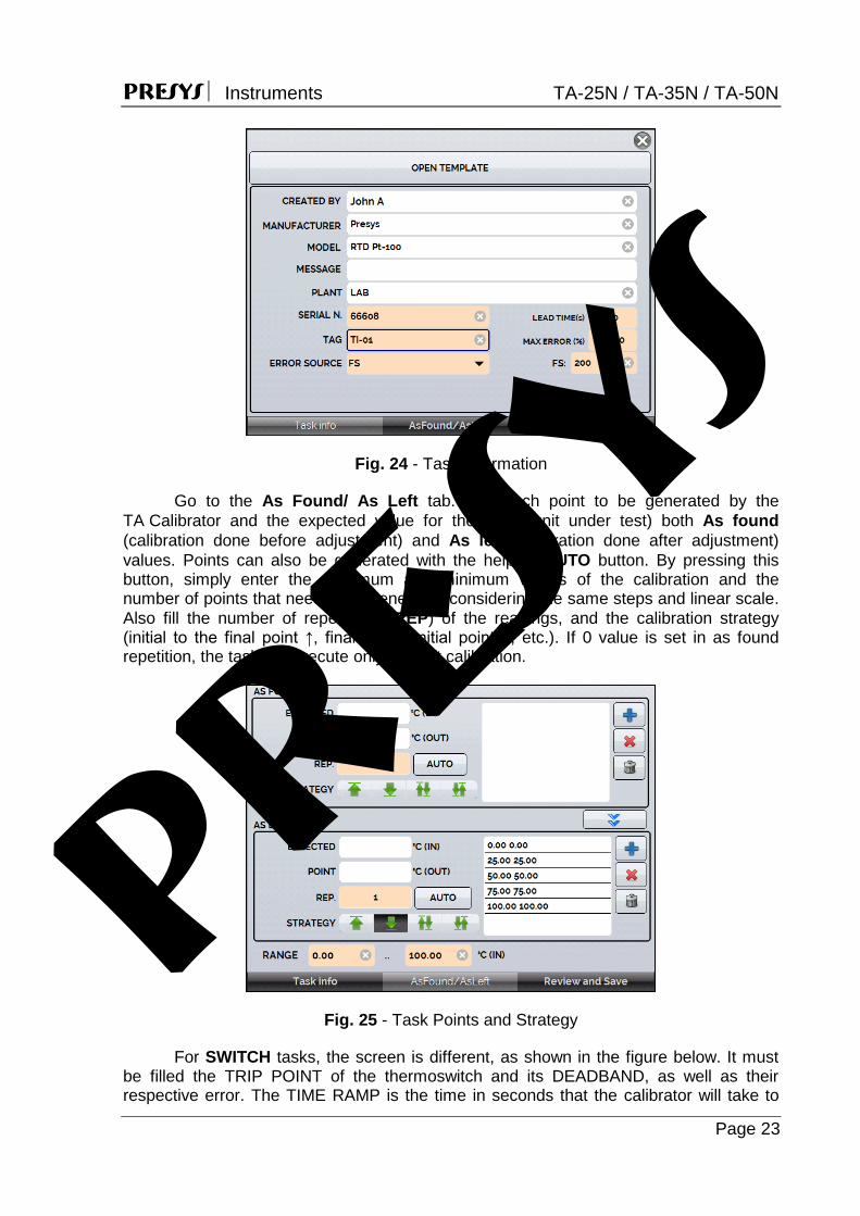
Press the icon, and select TASKS and CREATE NEW TASK. Fill at least the serial number of the instrument to calibrate, instrument TAG, lead
time (time, in seconds, for the complete stabilization of the system), maximum error allowed for the instrument to be calibrated (in % of the span, reading or full scale), calibration range.
presys
PRESYS Instruments TA-25N / TA-35N / TA-50N
Page 23
Fig. 24 - Task Information
Go to the As Found/ As Left tab. Add each point to be generated by the TA Calibrator and the expected value for the UUT (unit under test) both As found (calibration done before adjustment) and As left (calibration done after adjustment) values. Points can also be generated with the help of AUTO button. By pressing this button, simply enter the maximum and minimum values of the calibration and the number of points that need to be generated considering the same steps and linear scale. Also fill the number of repetitions (REP) of the readings, and the calibration strategy (initial to the final point ↑, final to the initial point ↓, etc.). If 0 value is set in as found repetition, the task will execute only As-Left calibration.
Fig. 25 - Task Points and Strategy
For SWITCH tasks, the screen is different, as shown in the figure below. It must be filled the TRIP POINT of the thermoswitch and its DEADBAND, as well as their respective error. The TIME RAMP is the time in seconds that the calibrator will take to
presys

PRESYS Instruments TA-25N / TA-35N / TA-50N
Page 24
tour the range and find the value of opening and closing the thermoswitch. The minimum value for this field is 300 s. Tip: If the Trip point and deadband are not known, try the THERMOSWITCH TEST to find an approximate value before creating the task.
Fig 26 – SWITCH Task Parameters
Go to the Review and Save tab and choose an identification name/number for
your task. If you want to save the model of this task for later use to create other tasks, press SAVE TEMPLATE and give a name for it. When you want to open this model again, open the task creation screen and press OPEN TEMPLATE in Task info tab.
Click on CREATE button to create it. The task is now saved in the calibrator.
Fig. 27 - Creating a Task pr
esys

PRESYS Instruments TA-25N / TA-35N / TA-50N
Page 25
2.3.2 - Performing Tasks
To perform a task created from the main menu select TASKS >
EXPLORE TASKS. A list of the created W.O. that have not been performed yet (● WAITING) is shown. Select the desired task and press OK. Make the necessary connections between the calibrator and the UUT and press START.
Fig. 28 - Exploring Tasks
The TA Calibrator automatically starts the execution of the calibration, generating the registered setpoints, waiting the stabilization of the system and reading the associated input values. If you selected the option NONE as input, for each generated point, the calibrator will require to digit the value of the temperature indicated by the instrument (thermometer, indicator…). The result will be displayed on the screen, and a progress bar indicates the calibration remaining time. At the end of the calibration, a report is showed with the generated values, the obtained values, the expected values, and the error. If the error is higher than the registered value for the task, the line appears in red. The first time that a task is performed, it will be saved as As-found (before adjustment). If it runs again, it will be saved as As-left (after adjustment). The results are saved in the calibrator and can be viewed at any time.
2.3.3 - Viewing Results
Once a task has been performed, it remains saved in the calibrator. To view the results of a calibration, in the main menu select TASKS. Select the option ● PERFORMED. The list will show only the tasks that have been
performed. Select the desired work order and press OK. The report with the calibration points, the obtained values, expected values and the errors will be shown. If the error is higher than the value registered for the task, the line appears in red.
presys
PRESYS Instruments TA-25N / TA-35N / TA-50N
Page 26
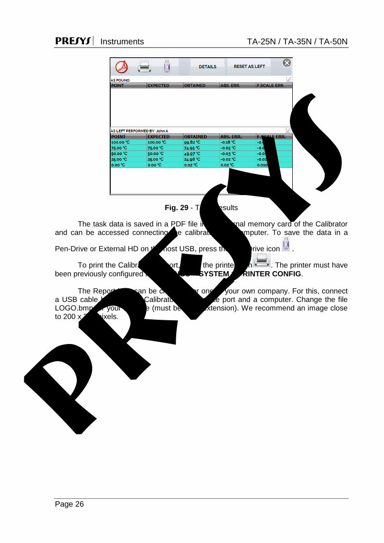
Fig. 29 - Task Results
The task data is saved in a PDF file in the internal memory card of the Calibrator and can be accessed connecting the calibrator to a computer. To save the data in a
Pen-Drive or External HD on the host USB, press the Pen-Drive icon .
To print the Calibration Report, press the printer icon . The printer must have been previously configured in SETTINGS > SYSTEM > PRINTER CONFIG.
The Report logo can be changed for one of your own company. For this, connect
a USB cable between TA Calibrator USB Device port and a computer. Change the file LOGO.bmp for your logo file (must be .bmp extension). We recommend an image close to 200 x 200 pixels.
presys
PRESYS Instruments TA-25N / TA-35N / TA-50N
Page 27
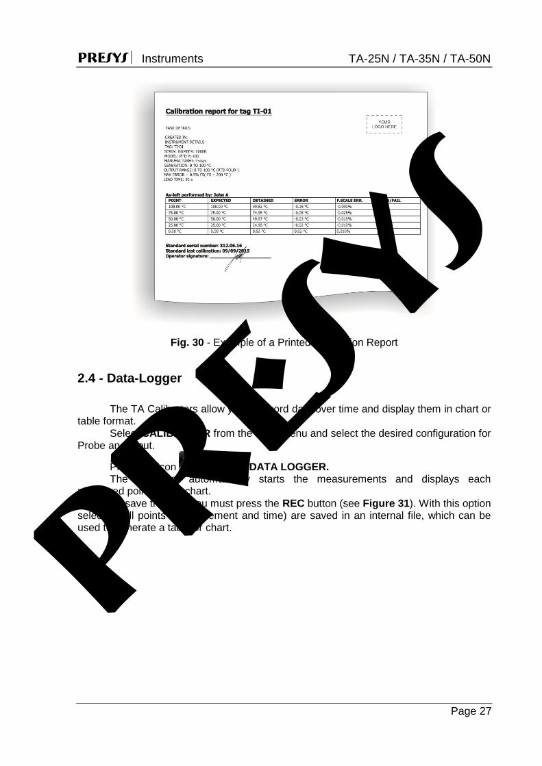
Fig. 30 - Example of a Printed Calibration Report
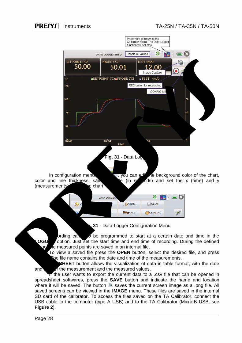
2.4 - Data-Logger The TA Calibrators allow you to record data over time and display them in chart or table format. Select CALIBRATOR from the main menu and select the desired configuration for Probe and Input.
Press the icon and select DATA LOGGER. The calibrator automatically starts the measurements and displays each
measured point on the chart. To save the data you must press the REC button (see Figure 31). With this option
selected, all points (measurement and time) are saved in an internal file, which can be used to generate a table or chart.
presys
PRESYS Instruments TA-25N / TA-35N / TA-50N
Page 28
Fig. 31 - Data Logger
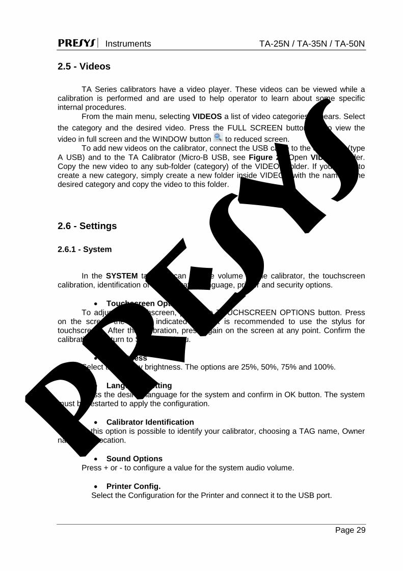
In configuration menu (icon , you can edit the background color of the chart, color and line thickness, sampling rate (in seconds) and set the x (time) and y (measurements) axis of the chart.
Fig. 31 - Data-Logger Configuration Menu
Recording can also be programmed to start at a certain date and time in the LOGGER option. Just set the start time and end time of recording. During the defined range, the measured points are saved in an internal file.
To view a saved file press the OPEN button, select the desired file, and press LOAD. The file name contains the date and time of the measurements.
The SHEET button allows the visualization of data in table format, with the date and time of the measurement and the measured values.
If the user wants to export the current data to a .csv file that can be opened in spreadsheet softwares, press the SAVE button and indicate the name and location where it will be saved. The button saves the current screen image as a .png file. All saved screens can be viewed in the IMAGE menu. These files are saved in the internal SD card of the calibrator. To access the files saved on the TA Calibrator, connect the USB cable to the computer (type A USB) and to the TA Calibrator (Micro-B USB, see Figure 2).
presys
PRESYS Instruments TA-25N / TA-35N / TA-50N
Page 29
2.5 - Videos TA Series calibrators have a video player. These videos can be viewed while a
calibration is performed and are used to help operator to learn about some specific internal procedures.
From the main menu, selecting VIDEOS a list of video categories appears. Select the category and the desired video. Press the FULL SCREEN button to view the video in full screen and the WINDOW button to reduced screen.
To add new videos on the calibrator, connect the USB cable to the computer (type A USB) and to the TA Calibrator (Micro-B USB, see Figure 2). Open VIDEOS folder. Copy the new video to any sub-folder (category) of the VIDEOS folder. If you prefer to create a new category, simply create a new folder inside VIDEOS with the name of the desired category and copy the video to this folder.
2.6 - Settings
2.6.1 - System
In the SYSTEM tab, you can set the volume of the calibrator, the touchscreen calibration, identification of the calibrator, language, printer and security options.
Touchscreen Options
To adjust the touchscreen, press the TOUCHSCREEN OPTIONS button. Press on the screen the places indicated by + (it is recommended to use the stylus for touchscreen). After the calibration, press again on the screen at any point. Confirm the calibration to return to SYSTEM Menu.
Brightness
Select the display brightness. The options are 25%, 50%, 75% and 100%.
Language Setting Press the desired language for the system and confirm in OK button. The system
must be restarted to apply the configuration.
Calibrator Identification In this option is possible to identify your calibrator, choosing a TAG name, Owner
name and Location.
Sound Options Press + or - to configure a value for the system audio volume.
Printer Config. Select the Configuration for the Printer and connect it to the USB port.
presys
PRESYS Instruments TA-25N / TA-35N / TA-50N
Page 30
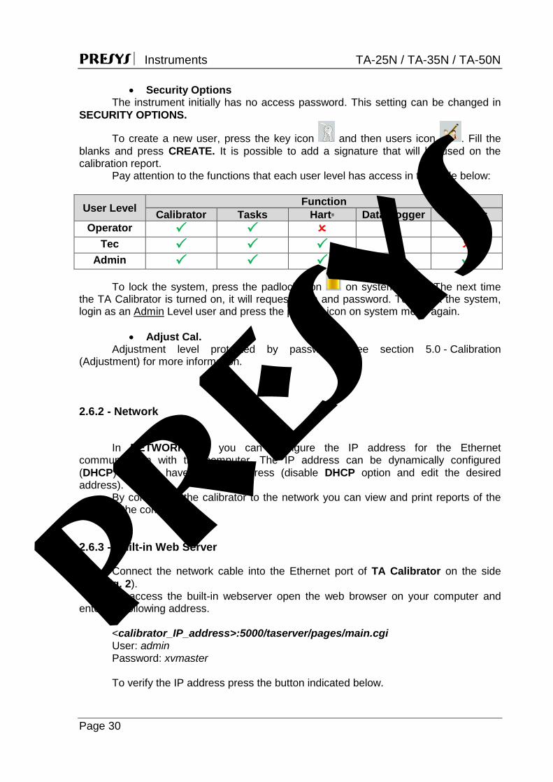
Security Options The instrument initially has no access password. This setting can be changed in SECURITY OPTIONS.
To create a new user, press the key icon and then users icon . Fill the blanks and press CREATE. It is possible to add a signature that will be used on the calibration report. Pay attention to the functions that each user level has access in the table below:
User Level Function Calibrator Tasks Hart® Data-Logger Settings
Operator Tec
Admin
To lock the system, press the padlock icon on system menu. The next time the TA Calibrator is turned on, it will request login and password. To unlock the system, login as an Admin Level user and press the padlock icon on system menu again.
Adjust Cal. Adjustment level protected by password. See section 5.0 - Calibration (Adjustment) for more information.
2.6.2 - Network
In NETWORK tab you can configure the IP address for the Ethernet communication with the computer. The IP address can be dynamically configured (DHCP) or may have a fixed address (disable DHCP option and edit the desired address). By connecting the calibrator to the network you can view and print reports of the tasks on the computer. 2.6.3 - Built-in Web Server
Connect the network cable into the Ethernet port of TA Calibrator on the side (see Fig. 2).
To access the built-in webserver open the web browser on your computer and enter the following address.
<calibrator_IP_address>:5000/taserver/pages/main.cgi User: admin Password: xvmaster
To verify the IP address press the button indicated below.
presys

PRESYS Instruments TA-25N / TA-35N / TA-50N
Page 31
Fig. 32 - IP address
Fig. 33 - TA Calibrator Web Server In the Web Server, you can monitor the calibrator screen, change the setpoint and see the auxiliary input readings. pr
esys

PRESYS Instruments TA-25N / TA-35N / TA-50N
Page 32
3 - Safety Instructions
If the calibrator is turned on, do not leave the room without an identification or warning
about the high temperature hazard. Before turning the calibrator off, return the block temperature to values close to the
ambient temperature. Never remove the insert from the dry block or the thermo-elements from the insert,
while they are in temperatures far from the ambient. Wait until they reach the ambient temperature so that the heterogeneous cooling of the parts do not jam each other.
4 - Recommendations as regards Accuracy of Measurements
PRESYS Temperature Advanced Calibrators are instruments of high accuracy
level, requiring the observation of all the procedures described in this section, in order to achieve the necessary conditions to get the accuracy levels during the calibrations. Special attention should be paid in relation to the insert cleanliness. When necessary,
it should always be washed with water and soap, well rinsed and dried. Oil, grease, solid particles can hinder the heat transference to the insert and even jam the insert inside the block.
The sensor to be calibrated must fit snugly into the appropriate well. In case the sensor is loose, the measurement accuracy meaning can be completely senseless. The meaning of clearance between the sensor and the respective well should be understood in a subjective way and the common sense is very important. Thus, the sensor should enter the insert well (both completely clean) in such a way to stay snugly enough so that it cannot move or swing inside but it should not enter by force to get jammed.
In the specific case of generating negative temperature, the calibrations should be performed in a descending temperature order. This procedure is useful because in negative temperatures ice is formed in the insert surface and between the insert and the thermo-element being calibrated. This humidity changes the thermal contact and cause error in the calibration. After finishing the use of the insert below 0 C, increase the setpoint to a positive temperature value, remove the insert from the block and the sensor and dry completely all these parts before continuing the calibration. This procedure guarantees accuracy next to 0.1 C. In case you can accept higher values of accuracy, like 0.2 C or more, these cares can be left apart.
5 - Calibration (Adjustment)
Warning: Enter the following options only after understanding them completely.
Otherwise, it may be necessary to return the instrument to the factory for recalibration!
presys
PRESYS Instruments TA-25N / TA-35N / TA-50N
Page 33
Select ADJUST/CAL option from the SETTINGS > SYSTEM menu. You should then enter the password 9875 to access the calibration menu.
The password functions as a protection to calibration ranges. After the password is entered, the menu displays the options GENERAL, INPUTS and PROBE.
Options for INPUTS are mV, mA, ohm and thermocouple. 5.1 - Input Calibration
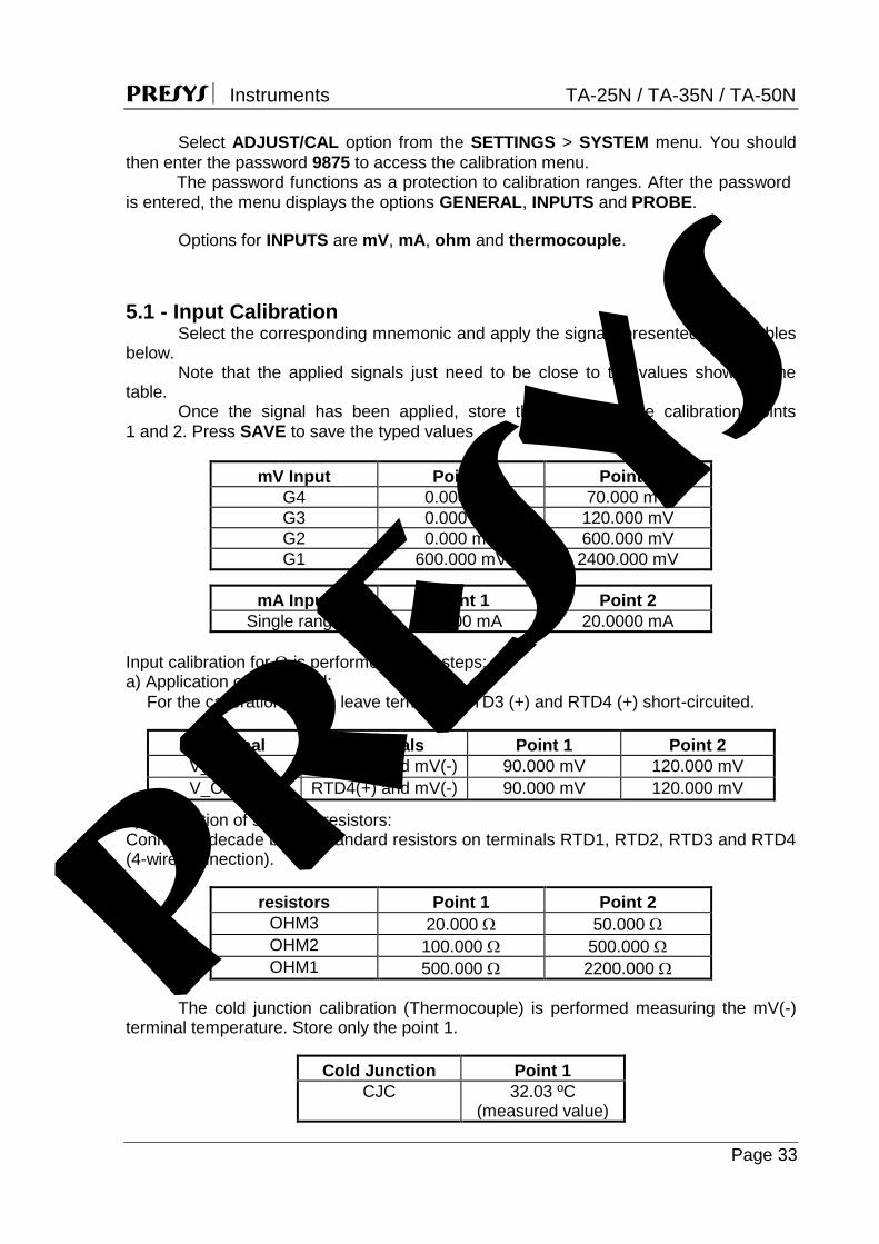
Select the corresponding mnemonic and apply the signals presented in the tables below.
Note that the applied signals just need to be close to the values shown in the table.
Once the signal has been applied, store the values of the calibration points 1 and 2. Press SAVE to save the typed values
mV Input Point 1 Point 2 G4 0.000 mV 70.000 mV G3 0.000 mV 120.000 mV G2 0.000 mV 600.000 mV G1 600.000 mV 2400.000 mV
mA Input Point 1 Point 2 Single range 0.0000 mA 20.0000 mA
Input calibration for is performed in two steps: a) Application of mV signal:
For the calibration below, leave terminals RTD3 (+) and RTD4 (+) short-circuited.
mV Signal Terminals Point 1 Point 2 V_OHM3 RTD3(+) and mV(-) 90.000 mV 120.000 mV V_OHM4 RTD4(+) and mV(-) 90.000 mV 120.000 mV
b) Application of standard resistors: Connect a decade box or standard resistors on terminals RTD1, RTD2, RTD3 and RTD4 (4-wire connection).
resistors Point 1 Point 2 OHM3 20.000 50.000 OHM2 100.000 500.000 OHM1 500.000 2200.000
The cold junction calibration (Thermocouple) is performed measuring the mV(-) terminal temperature. Store only the point 1.
Cold Junction Point 1 CJC 32.03 ºC
(measured value)
presys

PRESYS Instruments TA-25N / TA-35N / TA-50N
Page 34
5.2 - Probe Calibration
To readjust the internal Probe it is necessary to compare the value indicated by the calibrator (Probe) and the temperature value from a standard probe placed in the dry block insert. The temperature of the standard probe should have high accuracy.
The option to adjust the internal sensor has seven points of adjustment. These points are recorded via points 1 to 7.
Before starting the calibration (adjustment), record in these points the respective initial storing values, according to the table below:
For the TA-25N
Calibration Point
Initial value to record (°C)
Standard indication
New value to record
New indication
of the Standard
Point 1: -25 -25.00 -24.780 -24.78 -24.995 Point 2: -2 -2.00 -2.103 -2.10 -2.005 Point 3: 30 30.00 29.910 29.91 29.990 Point 4: 60 60.00 59.771 59.77 60.009 Point 5: 90 90.00 89.770 89.77 90.000 Point 6: 120 120.00 119.630 119.63 119.995 Point 7: 140 140.00 139.539 139.54 140.005
For the TA-35N
Calibration Point
Initial value to record (°C)
Standard indication
New value to record
New indication
of the Standard
Point 1: -35 -35.00 -34.780 -34.78 -34.995 Point 2: -2 -2.00 -2.103 -2.10 -2.005 Point 3: 30 30.00 29.910 29.91 29.990 Point 4: 60 60.00 59.771 59.77 60.009 Point 5: 90 90.00 89.770 89.77 90.000 Point 6: 120 120.00 119.630 119.63 119.995 Point 7: 140 140.00 139.539 139.54 140.005
For the TA-50N
Calibration Point
Initial value to record (°C)
Standard indication
New value to record
New indication
of the Standard
Point 1: -50 -50.00 -49.780 -49,78 -49.995 Point 2: -2 -2.00 -2.103 -2.10 -2.005 Point 3: 30 30.00 29.910 29.91 29.990 Point 4: 60 60.00 59.771 59.77 60.009 Point 5: 90 90.00 89.770 89.77 90.000 Point 6: 120 120.00 119.630 119.63 119.995 Point 7: 140 140.00 139.539 139.54 140.005
presys

PRESYS Instruments TA-25N / TA-35N / TA-50N
Page 35
Select the calibration point and then press CHANGE TEMPERATURE. Wait for the complete stabilization of the point. On the field Adjusted Point, write the value presented in the standard thermometer and confirm in SAVE button. Go to the next point and continue the adjustment until the last point.
6 - Maintenance 6.1 - Instructions for Hardware Maintenance There are no parts or components inside the temperature calibrator that can be repaired by the user. Only the 10 Amp fuse for 115V models or 6 Amp fuse for 230 V models, placed within the socket on the rear can be replaced in case of blow.
The fuse may blow due to a voltage spike in the mains or a calibrator component fault. Replace the fuse once. If a second fuse blows again, it is because the fault is not that simple. In this case, contact the Presys technical support. In case of malfunction of mA input, the input fuse (250 V/32 mA) can be exchanged.
6.2 - Instructions for Insert Jamming
If it happens that an insert jams inside the block proceed as follows. 1- apply a lubricant oil between the parts; 2- apply cooling liquid inside the insert wells in order to contract the insert; 3- try again to withdraw the insert. After taking the insert out, sand both the surfaces with thin sandpaper, polish
them with an suitable paste and finally clean the parts using alcohol or solvent.
presys

PRESYS Instruments TA-25N / TA-35N / TA-50N
Page 36
6.3 - Tiny Steel Balls, Recommendations of Use and Safety Instructions
The dry block calibrators accessories include a plastic container with tiny steel
balls. This item is an exclusive accessory of PRESYS dry block calibrators, which also
provide a cup-like insert that is an insert drilled with the maximum allowed diameter (3/4”), proper for being filled with the tiny balls.
With both the cup-like insert and the tiny balls, it is possible to calibrate temperature sensors with irregular shape or whose dimensions do not match the available insert holes. One should place the sensor to be calibrated in the insert and fulfill the remaining volume with the tiny balls.
It is important to note that accuracy gets worse in this kind of procedure because the dry block is calibrated in factory using an insert with an appropriate well that fits the standard sensor snugly. Thus, the accuracy specifications presented in this manual are not valid anymore. Anyway, consider an increase of up to five times the accuracy values.
To use the tiny balls and continue achieving accurate measurements it is necessary to read from an external reference sensor tied together with the sensor to be calibrated both plunged in the tiny balls. In order to join the sensors, one can use rigid copper wire. Wind them with several turns starting from the tip of the sensors.
Safety Instructions: Take care when using the cup-like insert and the tiny balls of steel.
Handle the balls or the sensors only when they are at ambient temperature. Operate the dry block calibrator in a proper location to prevent it from falling down or even to prevent the balls at high temperature from being spilled outside causing body burn or other damages or injuries.
presys

presys