Embed Size (px)
Citation preview

1. Introduction
Nanomaterials are the important part of the wider group of polycrystalline materials in which the grain size is less than 100 nm in at least one direction. It corresponds to a minimal mean distance between the intercrystalline boundaries which is smaller than 100nm [1-2]. Along with the development of nanomaterials, there is also a need to develop the methods of microstructure characterization. The methods commonly used for characterization of the multiphase steel microstructures are as follows: light microscopy (LM), scanning electron microscopy (SEM), transmission electron microscopy (TEM), electron back-scattered diffraction (EBSD) [3], X-ray diffraction analysis and the atom probe tomography (APT) [4]. However, some of the aforementioned methods have proved to be unreliable in nanoscale research.
Recently, many scientific studies have focused on the production of the nanocrystalline structure through bainitic transformation in different types of steel [5-7]. Austempering process with properly designed parameters leads to obtaining the nanobainitic structure which is mainly a mixture of two phases: very thin bainitic ferrite plates (20-40 nm thickness) and carbon-enriched retained austenite [8-10]. There are only scant publications in which the images of the nanobainitic structures
recorded with the use of atomic force microscopy (AFM) have been presented [11]. For this reason the AFM technique with modified probes was used in the present work to fully map and describe the microstructure. The aforementioned modification was described in details in [12]. The obtained 3D images were compared with TEM images.
2. Experimental procedure
The chemical composition of the sample of 100CrMnSi6-4 bearing steel used in this investigation was as follows: Fe, 0.93-1.05 C, 0.45-0.75 Si, 1.00-1.20 Mn, 1.40-1.65 Cr, max. 0.025 P, max. 0.15 S, max. 0.1 Mo (wt. %) [13]. The material was austempered with specially designed parameters which led to the nanocrystalline structure formation. The parameters were determined according to the previous dilatometric investigations of the phase transformations in bearing steel [14].
A sample with a diameter of 3 mm and the length of 10 mm was austenitized at 930°C for 30 min, then cooled down to the temperature of isothermal quenching (320°C) and kept at this temperature for the next 5 hours. This time was sufficient for the complete bainitic transformation.
A R C H I V E S O F M E T A L L U R G Y A N D M A T E R I A L S
Volume 60 2015 Issue 3DOI: 10.1515/amm-2015-0278
J. DwORECkA*,#, E. JEziErska*, J. rębiś*, k. rożniatowski*, w. świątnicki*
TEM & AFM - coMplEMEnTAry TEchnIquEs For sTrucTurAl chArAcTErIzATIon oF nAnobAInITIc sTEEl
TEM & AFM – koMplEMEnTArnE TEchnIkI chArAkTEryzAcjI sTrukTury nAnobAInITycznEj
The aim of this study was to analyse and to identify the phases which formed in 100CrMnSi6-4 bearing steel after the nanostructuring heat treatment. Especially designed thermal treatment parameters were applied in order to obtain a nanoba-initic structure. Two different microscopic techniques were used for the precise examination of the microstructures obtained: transmission electron microscopy (TEM) and atomic force microscopy (AFM). Both analyses confirm that the examined steel has a nanocrystalline structure. However, it was discovered that the selected analysis methods affected the results of the plate thickness measurements.
Keywords: Transmission electron microscopy (TEM), Atomic force microscopy (AFM), Nanobainite, Bearing steel
celem pracy była analiza struktury i identyfikacja faz powstałych podczas procesu nanostrukturyzacji stali łożyskowej 100crMnsi6-4. chcąc wytworzyć strukturę nanobainityczną przeprowadzono obróbkę cieplną o specjalnie dobranych para-metrach. następnie wykonano precyzyjną analizę otrzymanej mikrostruktury wykorzystując w tym celu dwie zaawansowane techniki mikroskopowe: transmisyjną mikroskopię elektronową (tEM) oraz mikroskopię sił atomowych (aFM). badania wykonane obiema technikami potwierdziły, że badano stal o strukturze nanobainitycznej. wykazano też, że zależnie od zasto-sowanej techniki badawczej otrzymano różnice w wartościach zmierzonych grubościach elementów struktury.
* warsaw UnivErsity oF tEchnology, FacUlty oF MatErials sciEncE and EnginEEring, 141 wołoska str., 02-507 warszawa, Poland# Corresponding author: [email protected]
1592
The whole process was performed with the use of Bähr’s DIL805L dilatometer.
Several thin foils were prepared for the TEM examination with the use of a standard procedure: 0.2 mm thick discs were cut with a wire saw; than thinned with a sandpaper to obtain a thickness of approximately 0.1 mm and finally finished with electrolytic polishing.
Microstructural studies were carried out with the use of Jeol JEM 3010 transmission electron microscope (at a maximum accelerating voltage of 300 kV) and with the use of Bruker’s atomic force microscope- Multimode VIII. AFM studies were carried out in the Tapping Mode (TM). Both TEM and AFM observations were performed on the same sample. On the basis of the obtained images the width of the bainitic ferrite plates (lα) and of the austenite layers (lγ) were measured.
3. results and discussion
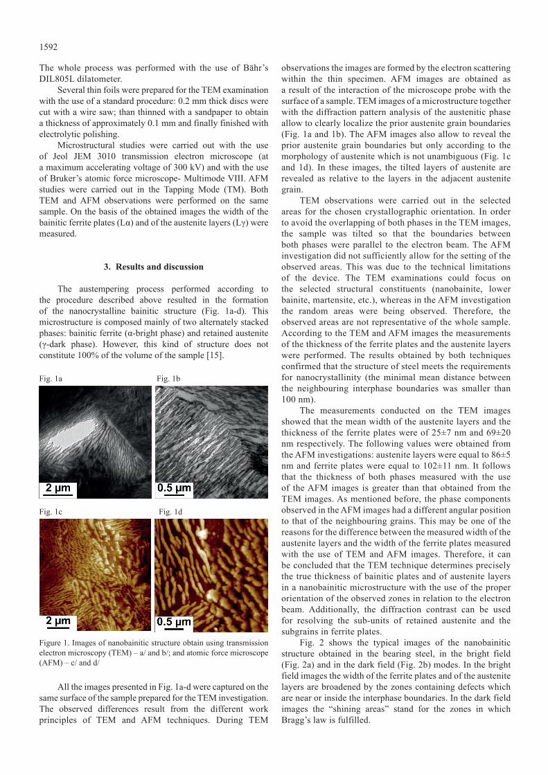
The austempering process performed according to the procedure described above resulted in the formation of the nanocrystalline bainitic structure (Fig. 1a-d). This microstructure is composed mainly of two alternately stacked phases: bainitic ferrite (α-bright phase) and retained austenite (γ-dark phase). however, this kind of structure does not constitute 100% of the volume of the sample [15].
Fig. 1a Fig. 1b
Fig. 1c Fig. 1d
Figure 1. Images of nanobainitic structure obtain using transmission electron microscopy (TEM) – a/ and b/; and atomic force microscope (AFM) – c/ and d/
All the images presented in Fig. 1a-d were captured on the same surface of the sample prepared for the TEM investigation. The observed differences result from the different work principles of TEM and AFM techniques. During TEM
observations the images are formed by the electron scattering within the thin specimen. AFM images are obtained as a result of the interaction of the microscope probe with the surface of a sample. TEM images of a microstructure together with the diffraction pattern analysis of the austenitic phase allow to clearly localize the prior austenite grain boundaries (Fig. 1a and 1b). The AFM images also allow to reveal the prior austenite grain boundaries but only according to the morphology of austenite which is not unambiguous (Fig. 1c and 1d). In these images, the tilted layers of austenite are revealed as relative to the layers in the adjacent austenite grain.
TEM observations were carried out in the selected areas for the chosen crystallographic orientation. In order to avoid the overlapping of both phases in the TEM images, the sample was tilted so that the boundaries between both phases were parallel to the electron beam. The AFM investigation did not sufficiently allow for the setting of the observed areas. This was due to the technical limitations of the device. The TEM examinations could focus on the selected structural constituents (nanobainite, lower bainite, martensite, etc.), whereas in the AFM investigation the random areas were being observed. Therefore, the observed areas are not representative of the whole sample. According to the TEM and AFM images the measurements of the thickness of the ferrite plates and the austenite layers were performed. The results obtained by both techniques confirmed that the structure of steel meets the requirements for nanocrystallinity (the minimal mean distance between the neighbouring interphase boundaries was smaller than 100 nm).
The measurements conducted on the TEM images showed that the mean width of the austenite layers and the thickness of the ferrite plates were of 25±7 nm and 69±20 nm respectively. The following values were obtained from the AFM investigations: austenite layers were equal to 86±5 nm and ferrite plates were equal to 102±11 nm. It follows that the thickness of both phases measured with the use of the AFM images is greater than that obtained from the TEM images. As mentioned before, the phase components observed in the AFM images had a different angular position to that of the neighbouring grains. This may be one of the reasons for the difference between the measured width of the austenite layers and the width of the ferrite plates measured with the use of TEM and AFM images. Therefore, it can be concluded that the TEM technique determines precisely the true thickness of bainitic plates and of austenite layers in a nanobainitic microstructure with the use of the proper orientation of the observed zones in relation to the electron beam. Additionally, the diffraction contrast can be used for resolving the sub-units of retained austenite and the subgrains in ferrite plates.
Fig. 2 shows the typical images of the nanobainitic structure obtained in the bearing steel, in the bright field (Fig. 2a) and in the dark field (Fig. 2b) modes. In the bright field images the width of the ferrite plates and of the austenite layers are broadened by the zones containing defects which are near or inside the interphase boundaries. In the dark field images the “shining areas” stand for the zones in which Bragg’s law is fulfilled.

1593
Fig. 2a Fig. 2b
Fig. 2c
Figure 2. TEM images presented nanobainitic structure obtained in austempering, with isothermal quenching in 320°C for 5 h: a/ in bright field, b/ dark field, c/ selected area electron diffraction
The example of the diffraction pattern of the selected area which is typical for nanostructured bainite in 100CrMnSi6-4 steel is shown on Fig. 2c. It presents two superimposed diffraction patterns which originate from both phases. In this case, the zone axis [001] of ferrite is parallel to the zone axis [011] of austenite. The orientation relationship between the two phases is close to the one of Nishyama-wassermann:
Ferrite [011] // austenite [111]Ferrite [011] // austenite [211]It was found that this type of orientation relationship is
characteristic of the nanobainitic structure in 100CrMnSi6-4 steel.
4. conclusions
• The conventional TEM images in the bright and dark field as well as the diffraction patterns analysis were used to identify the phases which occurred in the nanostructured bearing steel. It was revealed that the obtained microstructure consists of mutual arrangements of the nanometric plates of bainitic ferrite and of the layers of retained austenite. This microstructure meets the requirements for nanocrystallinity.
• The TEM technique allowed determining precisely the true thickness of the bainitic plates and of the austenite layers in a nanobainitic microstructure with the use of the
proper orientation of the observed zones in relation to the electron beam. The AFM method gave only an estimation of the thickness of the ferrite plates and of the austenite layers and it may require the additional adjustments.
• The use of the electron diffraction pattern analysis and of the precise orientation of the thin samples allowed to determine the crystallographic orientation relationships between the phases occurring in the examined steel.
• Microscopic observations performed with the use of TEM and AFM techniques on the same sample allowed a more complete characterisation of the nanobainitic microstructure.
Acknowledgements
The results presented in this paper have been obtained within the nanostal project (contract no. Poig 01.01.02-14-100/09). the project is co-financed by the European Union from the European Regional Development Fund within Operational Programme Innovative Economy 2007-2013.
REFERENCES
[1] w.G. kreyling, M. Semmler-Behnke, Q. Chaudhry, Nano Today 5, 165-168 (2010).
[2] k. kurzydłowski, M. lewandowska: nanomateriały inżynierskie konstrukcyjne i funkcjonalne, Polish scientific Publishers PwN, warsaw 2010.
[3] H. Beladi, Y. Adachi, I. Timokhina, P.D. Hodgson: Scripta Mater 60, 455-458 (2009).
[4] F.G. Caballero, M.k. Miller, S.S. Babu, C. Garci a-Mateo: Acta Mater 55, 381-390 (2007).
[5] T. Yokota, C. Garcia-Mateo, H. k. D. H. Bhadeshia, Scripta Mater 51, 767–770 (2004).
[6] H.k.D.H. Bhadeshia, Sci. Technol. Adv. Mater. 14 (2013), 014202.
[7] H.k.D.H. Bhadeshia, Proc. R. Soc. A 466, 3-18 (2010).[8] F.G. Caballero, H.k.D.H. Bhadeshia, H.J.A. Mawella,
D.G. Jones, P. Brown, Materials Science and Technology 18, 279-284 (2002).
[9] C. Garcia-Mateo, F.G. Caballero, H.k.D.H. Bhadeshia, ISIJ International 43, 1238–1243 (2003).
[10] F.G. Caballero, M. k. Miller, S. S. Babu, C. Garcia-Mateo, ISIJ International 43, 1821–1825, (2003).
[11] M.J. Peet: Transformation and tempering of low–temperature bainite, PhD thesis, Cambridge (2010).
[12] J. skibiński, J. rębiś, t. wejrzanowski, k. rożniatowski, k.J. kurzydłowski, Micron 66, 23-30 (2014).
[13] Standard: PN-EN ISO 683-17:2004[14] J. dworecka, E. Jezierska, k. rożniatowski, w. świątnicki,
Arch. Metall. Mater. 59, 1637-1640 (2014).[15] E. Jezierska, J. dworecka, k. rożniatowski, arch. Metall.
Mater. 59, 1633-1636 (2014).
Received: 20 February 2015