Embed Size (px)
Citation preview

Telma Owners ManualTL101009-AUG18
CONGRATULATIONS. Your vehicle is equipped with a TELMA Frictionless Braking System. Permanently connected to the driveline of your vehicle, it provides you with essential safety, cost effectiveness, accurate and reliable braking, and is ready to function under all circumstances. TELMA sup-plies your vehicle with an additional braking system that works along with your service brakes. You will benefit from improved braking resulting in increased safety and substantial savings on brakes, tires and route times.
Using your TELMA will reduce the use of the service brakes, which as a result, remain cool and fully effective for the occasions on which they are really need-ed – such as emergency stops. Read this guide before getting behind the wheel. It will tell you how to make the most of your TELMA.
CONTENTS PageTHEORY OF OPERATION SERVICE BRAKES & TELMA 1
HOW THEY WORK 1
CONTROLS BRAKE PEDAL APPLICATION 2 HAND CONTROL 2 OFF-THROTTLE CONTROL 2
COMPONENT TYPES OF TELMA MOUNTS 3IDENTIFICATION FOOT CONTROL SWITCHES 3 HAND CONTROL SWITCH 3 CONTROL MODULE (TRCM) 4 RELAY BOX 5 DASHBOARD INDICATOR 5
GENERAL PERIODIC INSPECTION CHECKLIST 6MAINTENANCE WASHING 7 AIR GAP MEASUREMENT 7ELECTRICAL IMPORTANT NOTES ABOUTMAINTENANCE GROUNDING THE SYSTEM 8 RELAY BOX CONTACTS 8 RELAY BOX DIODES 9 AMPERAGE CHECK 9
REPAIR & PARTS WIRING DIAGRAMS 10 PARTS CATALOGS AND REPAIR PROCEDURES 10
WARRANTY WARRANTY STATEMENT 11
THEORY OF OPERATION
Service Brakes & TELMA What are the service brakes designed to do? Stop the vehicle within a certain distance Hold the vehicle in place when stopped (parking brake)
What is the TELMA designed to do? Provide additional braking Provide braking without wear Provide braking without fade Provide extended service brake life
How They Work
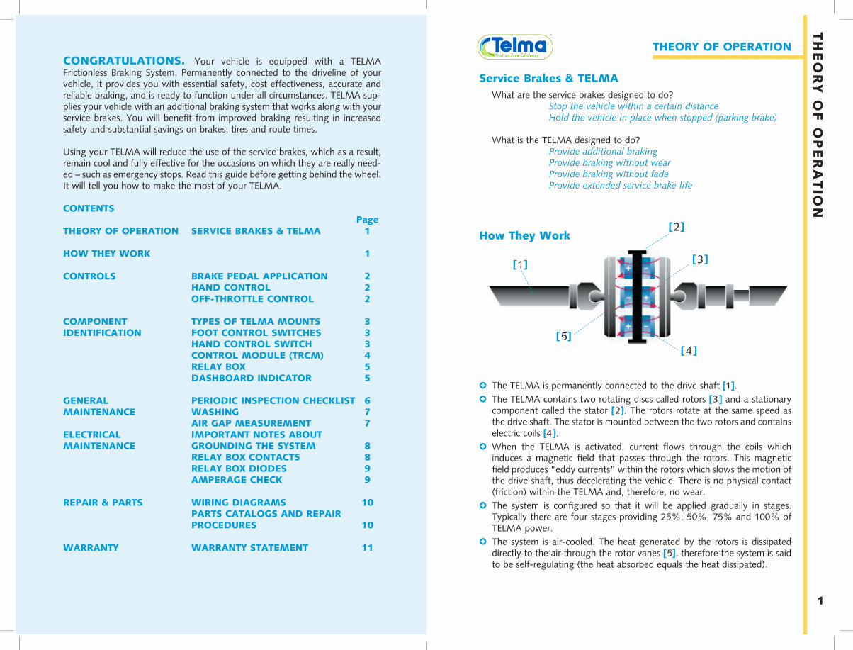
2The TELMA is permanently connected to the drive shaft [1].2The TELMA contains two rotating discs called rotors [3 ] and a stationary
component called the stator [2]. The rotors rotate at the same speed as the drive shaft. The stator is mounted between the two rotors and contains electric coils [4 ].
2 When the TELMA is activated, current flows through the coils which induces a magnetic field that passes through the rotors. This magnetic field produces “eddy currents” within the rotors which slows the motion of the drive shaft, thus decelerating the vehicle. There is no physical contact (friction) within the TELMA and, therefore, no wear.
2 The system is configured so that it will be applied gradually in stages. Typically there are four stages providing 25%, 50%, 75% and 100% of TELMA power.
2 The system is air-cooled. The heat generated by the rotors is dissipated directly to the air through the rotor vanes [5], therefore the system is said to be self-regulating (the heat absorbed equals the heat dissipated).
[1]
[2]
[3]
[4]
1
[5]
TH
EO
RY
OF
OP
ER
AT
ION

2
COMPONENT IDENTIFICATION
Types of TELMA MountsThere are two types of TELMAs: a driveline mount called “Axial” and a “Focal” which mounts directly to the differential. There is no difference in their operation; the difference is where the TELMA is mounted. The driveline “Axial” unit is located in the driveline between the transmission and the rear axle and mounts to the frame rail with brackets. The “Focal” is mounted directly to the drive axle differential.
Foot Control SwitchesOn air brake vehicles there is an air pressure transducer connected to the primary delivery line of the braking system to activate the retarder. On hydraulic brake vehicles there may be a rotary switch mounted with a bracket to the brake pedal. The pressure transducer or rotary switch sends an analog (variable voltage) signal to the Telma Control Module (TRCM). Each stage of the Telma can be activated at different voltage settings through the TRCM configuration software. Many vehicles broadcast brake pedal position information on the vehicle CANBus. In this case there will be no Telma foot switch needed or installed.
Hydraulic brake Rotary foot switch Air brake Pressure Transducer
CO
NT
RO
LS
Axial Focal
3
CO
MP
ON
EN
T ID
EN
TIF
ICA
TIO
N
Manual “Hand” Control SwitchA hand control switch can be used as the primary Telma control or it can be added as an option to the Telma foot control system.
CONTROLS
The TELMA can be controlled in several ways. Below are details of the types of control and the typical applications where they are used.
Brake Pedal Application (Foot Control)This type of control is used when it is desired to have automatic application when the brake pedal is applied. It is typically used in stop-and-go type applications where little driver training is needed. For best brake life anticipate stops and apply light pressure on the brake pedal to activate the four Telma stages progressively before the services brakes are used.
Manual “Hand” ControlThis type of control is used for mountain-ous applications where TELMA activation on long downgrades without applying the service brakes is desired. This type of control is manual so driver training is important. The vehicle should descend the grade in a gear, at a speed, and with occasional service brake application where only two Telma stages are needed to maintain speed and use a third and fourth stage only intermittently. The hand con-trol switch is typically mounted in the dash. To activate the TELMA, simply move the hand lever to one of the four powered positions. This type of control can also be used to preselect the number of stages to apply when the throttle is released. When the Telma is used in this fashion it is not progressive so no more than two stages (50%) should be selected when used in this way.
Off-Throttle ControlOff-throttle control allows the TELMA to be automatically activated when the driver lets off the accelerator pedal and before the brake pedal is applied. This type of control is not progressive so a maximum of two stages (50%) of Telma should be used in this manner. Off-throttle control is combined with foot control so the remaining stages are activated by the brake pedal
IMPORTANT! Do not forget to reset the hand control switch to Position 0 when the vehicle is stationary or when the TELMA is no longer required.
Brake Pedal
Hand Control

5
CO
MP
ON
EN
T ID
EN
TIF
ICA
TIO
N
4
CO
MP
ON
EN
T I
DE
NT
IFIC
AT
ION
The TRCM is the control module used to integrate the Telma system with the vehicle. It connects to the vehicle CANBus to read the messages below to control the Telma properly. A free software download from our website is used for configuration and diagnostics.
ABS ControlThe TRCM is designed to work with the vehicle Anti-Lock Braking System (ABS). During an ABS event (an ABS event is defined as an impending wheel slip condition) the ABS turns off the TELMA automatically, allowing the ABS to control the brakes without interference from TELMA. After the ABS event, the TELMA will reactivate progressively to assure proper braking.
Vehicle SpeedVehicle speed is monitored from the CANBus in order to turn off the Telma automatically when the vehicle comes to a stop. This low speed cutoff can be configured up to 2 mph using the TRCM configuration software.
Accelerator pedal positionAccelerator pedal position is monitored from the CANBus in order to turn off the Telma automatically whenever accelerator position is more than 1%. This prevents damage to the Telma if for any reason the vehicle is accelerated while the Telma is operating.
Brake pedal positionBrake pedal position is monitored from the CANBus or with an air pressure transducer or rotary foot switch in order to operate the Telma automatically whenever the brake pedal is applied. The TRCM configuration software allows the Telma stages to be configured so that the Telma activates before the service brakes apply.
Telma Control Module (TRCM)
IMPORTANT! The lights indicate that the TELMA is operating. They should never illuminate when the vehicle is stopped or when the accelera-tor is applied. If this occurs discontinue operation and drive the vehicle to the maintenance facility for immediate repair.
Relay BoxThe relay box is a high strength thermo-plastic enclosure that contains four relays mounted on a black plastic chassis. The box measures approximately 9-1/2” x 6-3/4” x 4 1/2”. The relay box distrib-utes battery power to the TELMA in four stages, and is usually mounted on the frame rail between the batteries and the TELMA. Battery power is connected to the relay assembly at the “+” terminal. When
voltage is applied to terminals 1, 2, 3 and 4, their respective relays close. This switches battery power to terminals I, II, III and IV respectively. The “M” ter-minal is the relay box ground and must be connected to the retarder ground post. The relay box should always be mounted in a vertical position with the wiring coming out of the bottom and should not be located close to a heat source such as the exhaust. The relay box should not be installed in an envi-ronment that will exceed 160°F (70°C).
Dashboard Indicator (Light Bar)The dashboard indicator (Light Bar) is the driver’s main indication of the TELMA’s function. This indicator contains four separate LEDs within the dis-play that are connected directly to the relay outputs which illuminate as the unit is activated. Each light corresponds to one of the stages of the unit. The lights will illuminate in succession as the TELMA is activated.

Periodic Inspections
It is recommended that the TELMA Periodic Inspection checklist be incorpo-rated into the regular vehicle maintenance schedule. The inspection inter-vals may vary depending upon the severity of operation and the annu-al mileage of the vehicle. The following inspection schedule is recommended:
Initial check
AtCheckEvery
CheckEvery
MILES 3,000 12,500 40,000HOURS 100 650 2,550
MONTHS 1 4 12
CHECK FOR END PLAY BETWEEN THE ROTOR AND STATOR
✓ ✓
RECORD AIR GAP AND ADJUST IF NECESSARY
✓ ✓
CHECK COILS, STATOR, AND ROTORS FOR DAMAGE
✓ ✓
INSPECT GREASE SEALS FOR LEAKS (AC/AD/AF SERIES)
✓ ✓
CHECK FASTENER TIGHTNESS ✓ ✓
CHECK CONDITION OF RUBBER MOUNTS (AC/AD/AF SERIES)
✓
CHECK GROUND, WIRING, RELAY BOX CONTACTS
✓ ✓
CHECK TELMA AMPS ARE WITHIN SPECIFICATIONS
✓ ✓
HYDRAULIC BRAKE FOOT SWITCH ADJUSTMENT
✓ ✓
ROAD TEST TO OBSERVE PROPER DASH LIGHT BAR FUNCTION
✓ ✓
ROAD TEST TO OBSERVE TELMA TURNS OFF AT STOP
✓ ✓
7
GE
NE
RA
L M
AIN
TE
NA
NC
E
IMPORTANT! In the case of any abnormalities, consult your TELMA Dealer or OEM as soon as possible for assistance.
6
GE
NE
RA
L M
AIN
TE
NA
NC
EGENERAL MAINTENANCE
The TELMA is a very low maintenance device. However, there are some general checks that should be done to make sure the TELMA continues to operate properly.
Washing
Driveline Units Focal Units
The TELMA should be pressure washed periodically. Visually inspect the unit to verify that it is clean and free of debris. If washing is necessary, please follow these guidelines:
2 Maximum pressure = 360 psi.2 Maximum temperature = 180º F.2 Keep washer tip at least 10” from the TELMA at all times.2 Coils should not be subjected to continuous direct pressure.2 Concentrate the stream on the rotors and air gap locations (as shown above).2 Do not wash the unit immediately after use.2 Do not use detergents or degreasing agents.2 Do not wash the unit if it is not necessary.
Air Gap MeasurementThe air gap distance between the rotors and the pole shoes is very important in the proper functioning of the TELMA. If the air gaps are too large, the unit will not provide the driver with the full braking power and efficiency that the TELMA is capable of. If the air gaps are too small, the rotors may interfere with the pole shoes and lead to unnecessary wear and premature failure of the TELMA or its components. The following checks should only be performed when the TELMA is cool. To verify the air gaps, use a feeler gauge to check clearances between the rotor and pole shoes at four points on each rotor. Refer to the individual TELMA data sheet and the video in the “How To” section of our website for correct air gap check and adjustment. Record measurements periodically according to the Inspection Chart schedule on the previous page and save in case of warranty claim.
Driveline Units Focal Units
9
EL
EC
TR
ICA
L M
AIN
TE
NA
NC
E
8
EL
ET
RIC
AL
MA
INT
EN
AN
CE
ELECTRICAL MAINTENANCE
Important Notes About Grounding the System
2A defective TELMA ground can cause poor performance.2A defective relay box ground can cause premature relay contact failure.2All ground circuits must return to battery negative with the correct wire size.2Relay box ground wire size must be: ____ minimum 10 gauge for TELMAs up to 20 amps per stage. ____ minimum 8 gauge for TELMAs up to 45 amps per stage. ____ minimum 6 gauge for TELMAs above 45 amps per stage.2TELMA ground wire size must be: ____ minimum 4 gauge for TELMAs up to 20 amps per stage. ____ minimum 2 gauge for TELMAs up to 45 amps per stage. ____ minimum 00 gauge for TELMAs above 45 amps per stage.2All ground points must be attached to a bare metal surface and protected
with anti-corrosion paint.
Relay Box
Relay Box Contacts• Relay box contacts are the only wear items in the Telma system.• Replace contacts whenever they become pitted and burned.• You can find part numbers for replacement contacts in the relay box parts
catalog and the contact replacement procedure at telmausa.com.
Relay Box Fuses• Each relay has a fuse on the output to protect against a short circuit that may
occur if a cable is damaged or the Telma develops a short circuit.• Spare fuses are included on relay 1.• Do not replace a fuse until the fault is found.• You can find the relay box fuse part number in the relay box parts catalog at
telmausa.com along with a fuse replacement procedure.
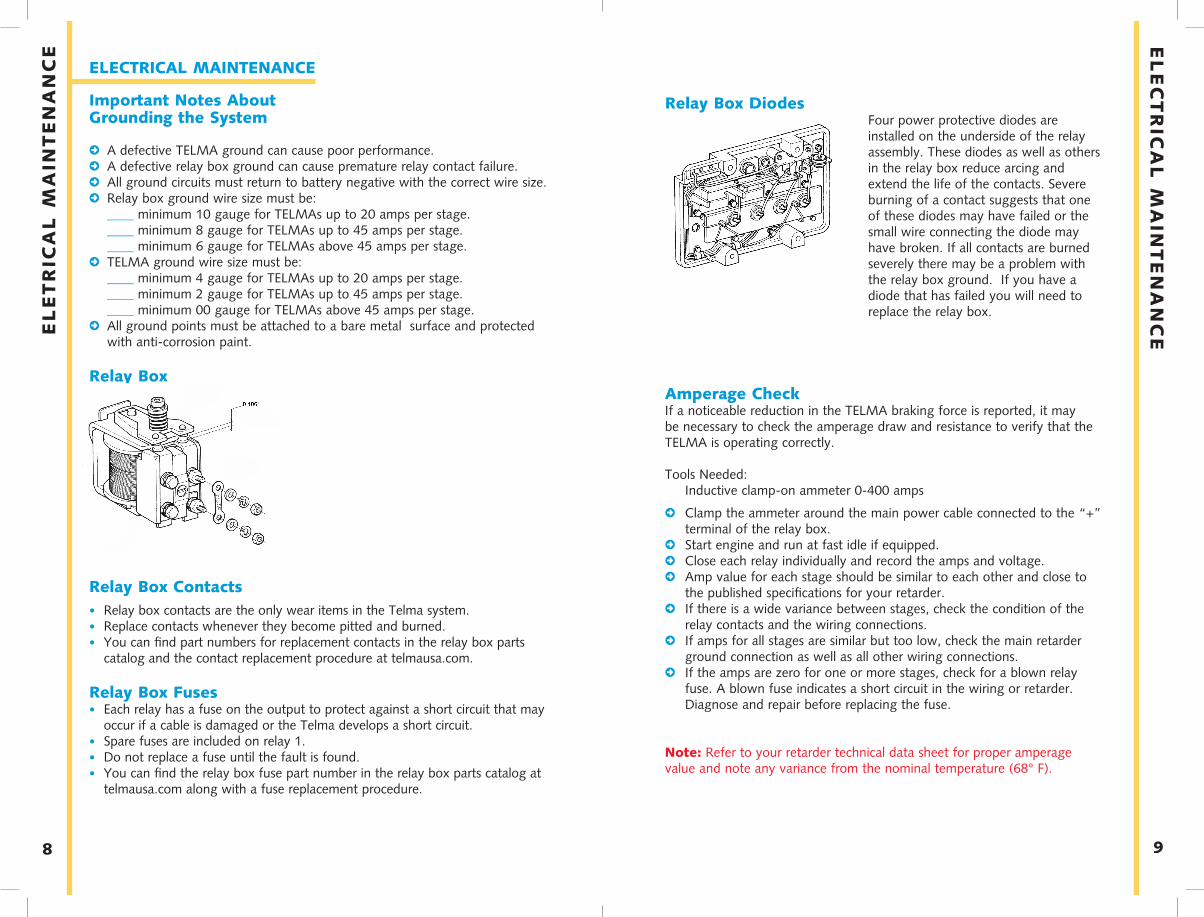
Relay Box DiodesFour power protective diodes are installed on the underside of the relay assembly. These diodes as well as others in the relay box reduce arcing and extend the life of the contacts. Severe burning of a contact suggests that one of these diodes may have failed or the small wire connecting the diode may have broken. If all contacts are burned severely there may be a problem with the relay box ground. If you have a diode that has failed you will need to replace the relay box.
Amperage CheckIf a noticeable reduction in the TELMA braking force is reported, it may be necessary to check the amperage draw and resistance to verify that the TELMA is operating correctly.
Tools Needed: Inductive clamp-on ammeter 0-400 amps
2 Clamp the ammeter around the main power cable connected to the “+” terminal of the relay box.
2 Start engine and run at fast idle if equipped.2 Close each relay individually and record the amps and voltage.2 Amp value for each stage should be similar to each other and close to
the published specifications for your retarder.2 If there is a wide variance between stages, check the condition of the
relay contacts and the wiring connections.2 If amps for all stages are similar but too low, check the main retarder
ground connection as well as all other wiring connections.2 If the amps are zero for one or more stages, check for a blown relay
fuse. A blown fuse indicates a short circuit in the wiring or retarder. Diagnose and repair before replacing the fuse.
Note: Refer to your retarder technical data sheet for proper amperage value and note any variance from the nominal temperature (68° F).

WARRANTY
Telma warrants to customers that the product shall be free from defects in materials and workmanship and will confirm to applicable specifications. TRI shall, at its option, repair correct or replace any product or part thereof which is defective in workman-ship of material: provided, however, that TRI is given prompt written notice of any failure (setting forth the alleged defect and pertinent delivery dates showing that the product is covered under the warranty) occurring within the lesser of a) two(2) years after the date of delivery to the first user of OEM product into which the product is installed of b) thirty (30) months from original delivery of the product. This Warranty does not cover a product or component thereof which fails, malfunc-tions or is damaged as a result of (i) improper installation, modification or repair, (ii) accident, abuse or improper or insufficient maintenance including deviation from approved lubricants or change intervals. In addition, this warranty does not cover normal wear and tear. This Warranty does not apply to products of compo-nents thereof not manufactured or supplied by TRI or to products of components thereof on vehicles operated outside the United States, Canada and Mexico. The warranty period for repairs or replacements is limited to the greater of 1) three (3) months or twenty-four thousand (24,000) miles, whichever shall occur first or 2) the expiration of date of the original warranty. THE EXPRESSED WARRANTIES HEREIN ARE IN LIEU OF ALL OTHER WARRANTIES, GUARANTEES, PROMISES, AFFIRMATIONS OR REPRESENTATIONS, EXPRESSED OR IMPLIED, INCLUDING, WITHOUT LIMITATION, WARRANTIES OF MERCHANTABILITY AND FITNESS FOR ANY PARTICULAR PURPOSE OR USE. TELMA SHALL NOT BE LIABLE FOR ANY INCIDENTAL, COLLATERAL, SPECIAL OR CONSEQUENTIAL LOSS, DAMAGE OR INJURY OF ANY NATURE INCLUDING, WITHOUT LIMITATION, SALES OR USE OF THE PRODUCTS WHETHER OR NOT OCCASIONED BY TELMA’S NEGLIGENCE OR OTHERWISE.
PRODUCT REGISTRATIONRegister your product at telmausa.com to start your warranty.
WARRANTY CLAIM PROCEDUREFor information about how a Telma warranty claim is processed, what is covered, flat rates, etc. visit telmausa.com and read through the Telma warranty Guidelines
SUBMIT A CLAIMIncident reports are submitted on our website at telmausa.com
10
RE
PA
IRS
AN
D P
AR
TS
REPAIRS AND PARTS
WIRING DIAGRAMSWiring Diagrams are unique to each vehicle application. Find the wiring diagram that applies to your vehicle at telmausa.com.
PARTS CATALOGS AND REPAIR PROCEDURESParts are available for all our retarders including electrical connectors, replacement coils, rotor sets, internal wiring sets, fasteners, etc. Visit telmausa.com to find the parts catalog and repair manual for your need.In addition, complete replacement bearing hub assemblies factory sealed and ready to install are available for our driveline “Axial” units.Repair procedures are also available at telmausa.com
11
WA
RR
AN
TY

NO
TE
SNotes
_________________________________________________________
_________________________________________________________
_________________________________________________________
_________________________________________________________
_________________________________________________________
_________________________________________________________
_________________________________________________________
_________________________________________________________
_________________________________________________________
_________________________________________________________
_________________________________________________________
_________________________________________________________
_________________________________________________________
_________________________________________________________
_________________________________________________________
_________________________________________________________
_________________________________________________________
_________________________________________________________
_________________________________________________________
_________________________________________________________
_________________________________________________________
_________________________________________________________
_________________________________________________________
_________________________________________________________
_________________________________________________________
_________________________________________________________
_________________________________________________________
Notes
_________________________________________________________
_________________________________________________________
_________________________________________________________
_________________________________________________________
_________________________________________________________
_________________________________________________________
_________________________________________________________
_________________________________________________________
_________________________________________________________
_________________________________________________________
_________________________________________________________
_________________________________________________________
_________________________________________________________
_________________________________________________________
_________________________________________________________
_________________________________________________________
_________________________________________________________
_________________________________________________________
_________________________________________________________
_________________________________________________________
_________________________________________________________
_________________________________________________________
_________________________________________________________
_________________________________________________________
_________________________________________________________
_________________________________________________________
_________________________________________________________
NO
TE
S

Telma Incorporatedwww.telmausa.com800.797.7714
TL101009-AUG18