Embed Size (px)
Citation preview

Telit Wireless M-Bus 2013 Part 4 User Guide 1VV0300953 Rev.14 – 2016-01-11
Telit Wireless M-Bus 2013 Part 4 User Guide
1VV0300953 Rev.14 – 2016-01-11
Reproduction forbidden without written authorization from Telit Communications S.p.A.- All Rights
Reserved. Page 2 of 70
APPLICABILITY TABLE
PRODUCT
ME50-868
ME50-169
ME70-169
SW Version
GC.U03.01.05
GI.U03.01.05
GL.U03.01.09
Telit Wireless M-Bus 2013 Part 4 User Guide
1VV0300953 Rev.14 – 2016-01-11
Reproduction forbidden without written authorization from Telit Communications S.p.A.- All Rights
Reserved. Page 3 of 70
SPECIFICATIONS SUBJECT TO CHANGE WITHOUT NOTICE
Notice
While reasonable efforts have been made to assure the accuracy of this document, Telit
assumes no liability resulting from any inaccuracies or omissions in this document, or from
use of the information obtained herein. The information in this document has been carefully
checked and is believed to be entirely reliable. However, no responsibility is assumed for
inaccuracies or omissions. Telit reserves the right to make changes to any products described
herein and reserves the right to revise this document and to make changes from time to time
in content hereof with no obligation to notify any person of revisions or changes. Telit does
not assume any liability arising out of the application or use of any product, software, or
circuit described herein; neither does it convey license under its patent rights or the rights of
others.
It is possible that this publication may contain references to, or information about Telit
products (machines and programs), programming, or services that are not announced in your
country. Such references or information must not be construed to mean that Telit intends to
announce such Telit products, programming, or services in your country.
Copyrights
This instruction manual and the Telit products described in this instruction manual may be,
include or describe copyrighted Telit material, such as computer programs stored in
semiconductor memories or other media. Laws in the Italy and other countries preserve for
Telit and its licensors certain exclusive rights for copyrighted material, including the
exclusive right to copy, reproduce in any form, distribute and make derivative works of the
copyrighted material. Accordingly, any copyrighted material of Telit and its licensors
contained herein or in the Telit products described in this instruction manual may not be
copied, reproduced, distributed, merged or modified in any manner without the express
written permission of Telit. Furthermore, the purchase of Telit products shall not be deemed
to grant either directly or by implication, estoppel, or otherwise, any license under the
copyrights, patents or patent applications of Telit, as arises by operation of law in the sale of a
product.
Computer Software Copyrights
The Telit and 3rd Party supplied Software (SW) products described in this instruction manual
may include copyrighted Telit and other 3rd Party supplied computer programs stored in
semiconductor memories or other media. Laws in the Italy and other countries preserve for
Telit and other 3rd Party supplied SW certain exclusive rights for copyrighted computer
programs, including the exclusive right to copy or reproduce in any form the copyrighted
computer program. Accordingly, any copyrighted Telit or other 3rd Party supplied SW
computer programs contained in the Telit products described in this instruction manual may
not be copied (reverse engineered) or reproduced in any manner without the express written
permission of Telit or the 3rd Party SW supplier. Furthermore, the purchase of Telit products
shall not be deemed to grant either directly or by implication, estoppel, or otherwise, any
license under the copyrights, patents or patent applications of Telit or other 3rd Party supplied
SW, except for the normal non-exclusive, royalty free license to use that arises by operation
of law in the sale of a product.

Telit Wireless M-Bus 2013 Part 4 User Guide
1VV0300953 Rev.14 – 2016-01-11
Reproduction forbidden without written authorization from Telit Communications S.p.A.- All Rights
Reserved. Page 4 of 70
Usage and Disclosure Restrictions
License Agreements
The software described in this document is the property of Telit and its licensors. It is
furnished by express license agreement only and may be used only in accordance with the
terms of such an agreement.
Copyrighted Materials
Software and documentation are copyrighted materials. Making unauthorized copies is
prohibited by law. No part of the software or documentation may be reproduced, transmitted,
transcribed, stored in a retrieval system, or translated into any language or computer language,
in any form or by any means, without prior written permission of Telit
High Risk Materials
Components, units, or third-party products used in the product described herein are NOT
fault-tolerant and are NOT designed, manufactured, or intended for use as on-line control
equipment in the following hazardous environments requiring fail-safe controls: the operation
of Nuclear Facilities, Aircraft Navigation or Aircraft Communication Systems, Air Traffic
Control, Life Support, or Weapons Systems (High Risk Activities"). Telit and its supplier(s)
specifically disclaim any expressed or implied warranty of fitness for such High Risk
Activities.
Trademarks
TELIT and the Stylized T Logo are registered in Trademark Office. All other product or
service names are the property of their respective owners.
Copyright © Telit Communications S.p.A. 2015.
Telit Wireless M-Bus 2013 Part 4 User Guide
1VV0300953 Rev.14 – 2016-01-11
Reproduction forbidden without written authorization from Telit Communications S.p.A.- All Rights
Reserved. Page 5 of 70
Contents
1. Introduction .................................................. 7
1.1. Scope ...................................................... 7
1.2. Audience ................................................... 7
1.3. Contact Information, Support ............................... 7
1.4. Document Organization ...................................... 8
1.5. Text Conventions ........................................... 8
1.6. Related Documents .......................................... 9
2. Wireless M-Bus Overview ...................................... 10
2.1. Definition of Wireless M-Bus .............................. 10
2.2. Wireless M-Bus Presentation ............................... 10
2.2.1. Mode T ....................................................... 10
2.2.2. Mode R2 ...................................................... 11
2.2.3. Mode S ....................................................... 11
2.2.4. Mode C ....................................................... 11
2.2.5. Mode N ....................................................... 11
2.2.6. Mode F ....................................................... 12
2.3. Data Format on RF Link .................................... 12
2.3.1. Frame Format A ............................................... 12
2.3.2. Frame Format B ............................................... 13
2.3.3. Field Definitions ............................................ 13
2.3.4. Extended Link Layer .......................................... 15
2.3.5. Data Header .................................................. 16
3. Software Operation ........................................... 18
3.1. Configuration Mode ........................................ 18
3.2. Register List ............................................. 21
3.3. Operating Mode ............................................ 31
3.3.1. Serial Frame on Transmission ................................. 31
3.3.2. Serial Frame on Reception .................................... 34
3.4. Stand-by Mode ................................................ 36
3.4.1. Wakeup of the Module ............................................. 36
3.4.2. Wakeup of External User Equipment ............................ 37
3.5. Advanced Features ......................................... 37
3.5.1. Hardware Flow Control ........................................ 37
3.5.2. Listen Before Talk ........................................... 37

Telit Wireless M-Bus 2013 Part 4 User Guide
1VV0300953 Rev.14 – 2016-01-11
Reproduction forbidden without written authorization from Telit Communications S.p.A.- All Rights
Reserved. Page 6 of 70
3.5.3. Date and Time ................................................ 41
3.5.4. Frame Format B ............................................... 41
3.5.5. Registered Meters ............................................ 42
3.5.6. Frame Filtering .............................................. 42
3.5.7. Encryption ................................................... 44
3.5.8. Remote AT Commands ........................................... 45
3.5.9. Automatic frame transmission ................................. 45
3.5.10. ............................................................................. Synchronized frame transmission 49
3.5.11. ............................................................................................................ Repeater operation 50
3.5.12. .................................................................................... Multichannel mode (ME70-169) 51
3.5.13. .................................................................................................. Indications (ME70-169) 53
3.5.14. ...........................................................................Frequent Access Cycle (ME70-169) 58
4. Power Consumption ............................................ 65
4.1. S1 Mode ................................................... 65
4.2. R2 Mode ................................................... 66
5. Acronyms and Abbreviations ................................... 68
6. Document History ............................................. 69

Telit Wireless M-Bus 2013 Part 4 User Guide
1VV0300953 Rev.14 – 2016-01-11
Reproduction forbidden without written authorization from Telit Communications S.p.A.- All Rights
Reserved. Page 7 of 70
1. Introduction
1.1. Scope
Scope of this document is to present the features and the application of the Wireless M-Bus
EN 13757-4:2013 embedded stack available on ME50-868, ME50-169 and ME70-169.
1.2. Audience
This document is intended for software developers and system integrators using MEx0
modules with Wireless M-Bus EN 13757-4:2013 firmware.
1.3. Contact Information, Support
For general contact, technical support, to report documentation errors and to order manuals,
contact Telit Technical Support Center (TTSC) at:
Alternatively, use:
http://www.telit.com/en/products/technical-support-center/contact.php
For detailed information about where you can buy the Telit modules or for recommendations
on accessories and components visit:
http://www.telit.com
To register for product news and announcements or for product questions contact Telit
Technical Support Center (TTSC).
Our aim is to make this guide as helpful as possible. Keep us informed of your comments and
suggestions for improvements.
Telit appreciates feedback from the users of our information.
Telit Wireless M-Bus 2013 Part 4 User Guide
1VV0300953 Rev.14 – 2016-01-11
Reproduction forbidden without written authorization from Telit Communications S.p.A.- All Rights
Reserved. Page 8 of 70
1.4. Document Organization
This document contains the following chapters:
“Chapter 1: “Introduction” provides a scope for this document, target audience, contact and
support information, and text conventions.
“Chapter 2: “Wireless M-Bus Overview” gives an overview of the Wireless M-Bus protocol.
“Chapter 3: “Software Operation” describes the operation of the Wireless M-Bus EN 13757-
4:2013 firmware and how it interfaces with an external host.
“Chapter 4: “Power Consumption” provides information on the module power consumption
in different operating conditions.
1.5. Text Conventions
Danger – This information MUST be followed or catastrophic equipment failure or bodily
injury may occur.
Caution or Warning – Alerts the user to important points about integrating the module, if
these points are not followed, the module and end user equipment may fail or malfunction.
Tip or Information – Provides advice and suggestions that may be useful when
integrating the module.
Telit Wireless M-Bus 2013 Part 4 User Guide
1VV0300953 Rev.14 – 2016-01-11
Reproduction forbidden without written authorization from Telit Communications S.p.A.- All Rights
Reserved. Page 9 of 70
1.6. Related Documents
EN 300 220-2 v2.4.1
ERC Recommendation 70-03
IEC 60870-5-2
EN 13757-3:2012
EN 13757-4:2013
Open Metering System Specification – Primary Communication – Issue 2.0.0
Dutch Smart Meter Requirements v4.0 – P2 Companion Standard
Telit xE50-433/868 RF Module User Guide, 1VV0300905
Telit ME50-169 RF Module User Guide, 1VV0300981
Telit ME70-169 RF Module User Guide, 1VV0301021
CIG Interchangeability Task Force TS 11291-11-4 & TS 11291-11-7

Telit Wireless M-Bus 2013 Part 4 User Guide
1VV0300953 Rev.14 – 2016-01-11
Reproduction forbidden without written authorization from Telit Communications S.p.A.- All Rights
Reserved. Page 10 of 70
2. Wireless M-Bus Overview
2.1. Definition of Wireless M-Bus
M-Bus (Meter-Bus) is a European Standard for remote reading of gas, water or electricity
meters. M-Bus is also usable for other types of consumption meters. The M-Bus interface is
made for communication on two wires, making it very cost effective.
This protocol exists with several physical layers such as paired wires, optical fiber or radio
link.
The radio variant of M-Bus is called Wireless M-Bus and is specified in EN 13757-4. It is
dedicated to the European ISM frequency bands at 169, 433 and 868 MHz.
It means that modules embedding the Wireless M-bus stack must comply with the general
SRD standard EN 300 220.
2.2. Wireless M-Bus Presentation
Devices communicating with Wireless M-Bus technology are classified as either meters or
‘other’ devices: the role of meters is to transmit utility consumption data, while ‘other’
devices (also referred to as concentrators) are in charge of collecting those data and can
optionally send commands to meters.
The Wireless M Bus specification EN 13757-4:2013 defines six different ways to exchange
data with remote meters:
Mode S ‘Stationary’
Mode T ‘frequent Transmit’
Mode R2 ‘frequent Receive’
Mode C ‘Compact’
Mode N ‘Narrowband VHF’
Mode F ‘Frequent receive and transmit’
ME50-868 with the firmware described in this document supports all the modes designed for
the 868 MHz frequency band, namely modes S, T, R2 and C, while ME50-169 and ME70-
169 support mode N at 169 MHz.
2.2.1. Mode T
In mode T, the meter sends spontaneously data, either periodically or stochastically. Frame
transmission from meters to other devices uses a bit rate of 100 kbps, while communication in
the opposite direction is carried out at 32.768 kbps.
In Mode T1 the meter doesn’t care if any receiver is present or not. The meter sends
data and returns immediately in power-save mode without waiting for a response.
This is a unidirectional communication.
Telit Wireless M-Bus 2013 Part 4 User Guide
1VV0300953 Rev.14 – 2016-01-11
Reproduction forbidden without written authorization from Telit Communications S.p.A.- All Rights
Reserved. Page 11 of 70
In Mode T2 the meter sends its data and stays awake during a short time immediately
after transmission to listen to a possible response frame. If no response is received,
the meter returns in power-save mode. If a response is received, then a bidirectional
communication link is opened between meter and concentrator.
2.2.2. Mode R2
In Mode R2 the meter doesn’t send spontaneously data. The meter wakes up periodically in
Rx mode and waits for a wakeup frame received from concentrator. If no frame is received,
the meter returns in power-save mode. If a valid wakeup frame is received, a bidirectional
link is then opened between meter and concentrator. The bit rate used in this mode is 4.8
kbps.
2.2.3. Mode S
The bit rate for radio communication is 32.768 kbps. The following two sub-modes are
defined:
Mode S1 operates exactly as Mode T1 (unidirectional spontaneous transmission) but
uses a different radio link.
Mode S2 is similar to Mode T2 (meter sends a frame and waits for a response during
a short interval) but also with a different physical link.
2.2.4. Mode C
This mode is similar to mode T but uses a different encoding scheme (NRZ); communication
from meters to other devices is at 100 kbps, while in the opposite direction a 50 kbps bit rate
is used. Two sub-modes are defined, C1 for unidirectional communication from meters to
other devices and C2 for bidirectional communication.
2.2.5. Mode N
It uses narrowband communication in the 169 MHz frequency band; the two sub-modes N1
and N2 are for unidirectional and bidirectional communication, respectively. The standard
Wireless M-Bus defines different channels, with different bit rates and modulation types, as
listed below:
Channel 1a: 4.8 kbps, GFSK modulation
Channel 1b: 4.8 kbps, GFSK modulation
Channel 2a: 2.4 kbps, GFSK modulation
Channel 2b: 2.4 kbps, GFSK modulation
Channel 3a: 4.8 kbps, GFSK modulation
Channel 3b: 4.8 kbps, GFSK modulation
Channel 0: 19.2 kbps, 4-GFSK modulation
Telit Wireless M-Bus 2013 Part 4 User Guide
1VV0300953 Rev.14 – 2016-01-11
Reproduction forbidden without written authorization from Telit Communications S.p.A.- All Rights
Reserved. Page 12 of 70
Additionally, the CIG interchangeable Task Force defines that channels 2a and 2b can be
accessed at 2.4 kbps or 4.8 kbps.
2.2.6. Mode F
It is a bidirectional mode operating at 2.4 kbps in the 433 MHz frequency band;
communication can be initiated by either the meter (similar to Mode T2) or the concentrator
(using a wakeup frame as is done in Mode R2).
2.3. Data Format on RF Link
EN 13757-4:2013 defines two different packet formats, namely format A and B. Multi-byte
fields described in the following subsections are transmitted least significant byte first, except
the CRC fields, which are transmitted most significant byte first.
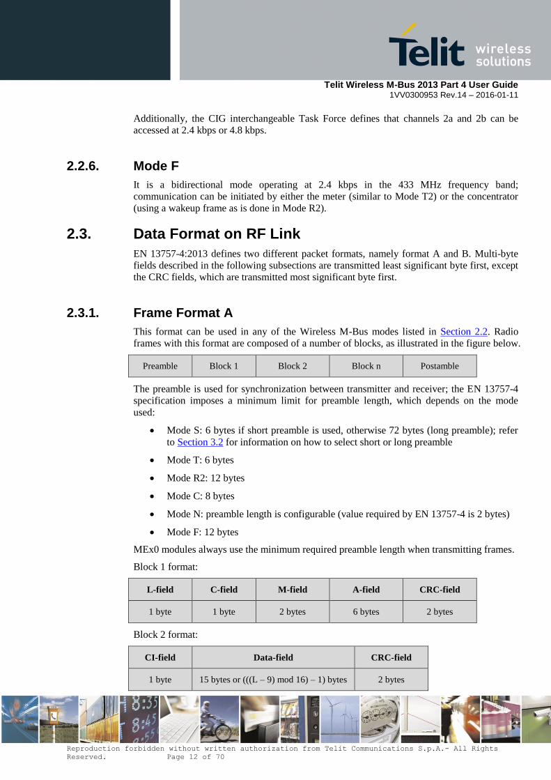
2.3.1. Frame Format A
This format can be used in any of the Wireless M-Bus modes listed in Section 2.2. Radio
frames with this format are composed of a number of blocks, as illustrated in the figure below.
Preamble Block 1 Block 2 Block n Postamble
The preamble is used for synchronization between transmitter and receiver; the EN 13757-4
specification imposes a minimum limit for preamble length, which depends on the mode
used:
Mode S: 6 bytes if short preamble is used, otherwise 72 bytes (long preamble); refer
to Section 3.2 for information on how to select short or long preamble
Mode T: 6 bytes
Mode R2: 12 bytes
Mode C: 8 bytes
Mode N: preamble length is configurable (value required by EN 13757-4 is 2 bytes)
Mode F: 12 bytes
MEx0 modules always use the minimum required preamble length when transmitting frames.
Block 1 format:
L-field C-field M-field A-field CRC-field
1 byte 1 byte 2 bytes 6 bytes 2 bytes
Block 2 format:
CI-field Data-field CRC-field
1 byte 15 bytes or (((L – 9) mod 16) – 1) bytes 2 bytes
Telit Wireless M-Bus 2013 Part 4 User Guide
1VV0300953 Rev.14 – 2016-01-11
Reproduction forbidden without written authorization from Telit Communications S.p.A.- All Rights
Reserved. Page 13 of 70
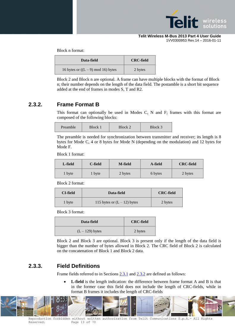
Block n format:
Data-field CRC-field
16 bytes or ((L – 9) mod 16) bytes 2 bytes
Block 2 and Block n are optional. A frame can have multiple blocks with the format of Block
n; their number depends on the length of the data field. The postamble is a short bit sequence
added at the end of frames in modes S, T and R2.
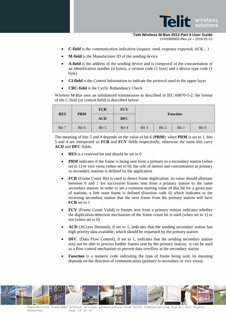
2.3.2. Frame Format B
This format can optionally be used in Modes C, N and F; frames with this format are
composed of the following blocks:
Preamble Block 1 Block 2 Block 3
The preamble is needed for synchronization between transmitter and receiver; its length is 8
bytes for Mode C, 4 or 8 bytes for Mode N (depending on the modulation) and 12 bytes for
Mode F.
Block 1 format:
L-field C-field M-field A-field CRC-field
1 byte 1 byte 2 bytes 6 bytes 2 bytes
Block 2 format:
CI-field Data-field CRC-field
1 byte 115 bytes or (L – 12) bytes 2 bytes
Block 3 format:
Data-field CRC-field
(L – 129) bytes 2 bytes
Block 2 and Block 3 are optional. Block 3 is present only if the length of the data field is
bigger than the number of bytes allowed in Block 2. The CRC field of Block 2 is calculated
on the concatenation of Block 1 and Block 2 data.
2.3.3. Field Definitions
Frame fields referred to in Sections 2.3.1 and 2.3.2 are defined as follows:
L-field is the length indication: the difference between frame format A and B is that
in the former case this field does not include the length of CRC-fields, while in
format B frames it includes the length of CRC-fields
Telit Wireless M-Bus 2013 Part 4 User Guide
1VV0300953 Rev.14 – 2016-01-11
Reproduction forbidden without written authorization from Telit Communications S.p.A.- All Rights
Reserved. Page 14 of 70
C-field is the communication indication (request, send, response expected, ACK…)
M-field is the Manufacturer ID of the sending device
A-field is the address of the sending device and is composed of the concatenation of
an identification number (4 bytes), a version code (1 byte) and a device type code (1
byte)
CI-field is the Control Information to indicate the protocol used to the upper layer
CRC-field is the Cyclic Redundancy Check
Wireless M-Bus uses an unbalanced transmission as described in IEC 60870-5-2; the format
of the C-field (or control field) is described below:
RES PRM
FCB FCV
Function
ACD DFC
Bit 7 Bit 6 Bit 5 Bit 4 Bit 3 Bit 2 Bit 1 Bit 0
The meaning of bits 5 and 4 depends on the value of bit 6 (PRM): when PRM is set to 1, bits
5 and 4 are interpreted as FCB and FCV fields respectively, otherwise the same bits carry
ACD and DFC fields.
RES is a reserved bit and should be set to 0
PRM indicates if the frame is being sent from a primary to a secondary station (when
set to 1) or vice versa (when set to 0); the role of meters and concentrators as primary
or secondary stations is defined by the application
FCB (Frame Count Bit) is used to detect frame duplication: its value should alternate
between 0 and 1 for successive frames sent from a primary station to the same
secondary station; in order to set a common starting value of this bit for a given pair
of stations, a link reset frame is defined (function code 0) which indicates to the
receiving secondary station that the next frame from the primary station will have
FCB set to 1
FCV (Frame Count Valid) in frames sent from a primary station indicates whether
the duplication detection mechanism of the frame count bit is used (when set to 1) or
not (when set to 0)
ACD (ACcess Demand), if set to 1, indicates that the sending secondary station has
high priority data available, which should be requested by the primary station
DFC (Data Flow Control), if set to 1, indicates that the sending secondary station
may not be able to process further frames sent by the primary station; it can be used
as a flow control mechanism to prevent data overflow at the secondary station
Function is a numeric code indicating the type of frame being sent; its meaning
depends on the direction of communication (primary to secondary or vice versa)
Telit Wireless M-Bus 2013 Part 4 User Guide
1VV0300953 Rev.14 – 2016-01-11
Reproduction forbidden without written authorization from Telit Communications S.p.A.- All Rights
Reserved. Page 15 of 70
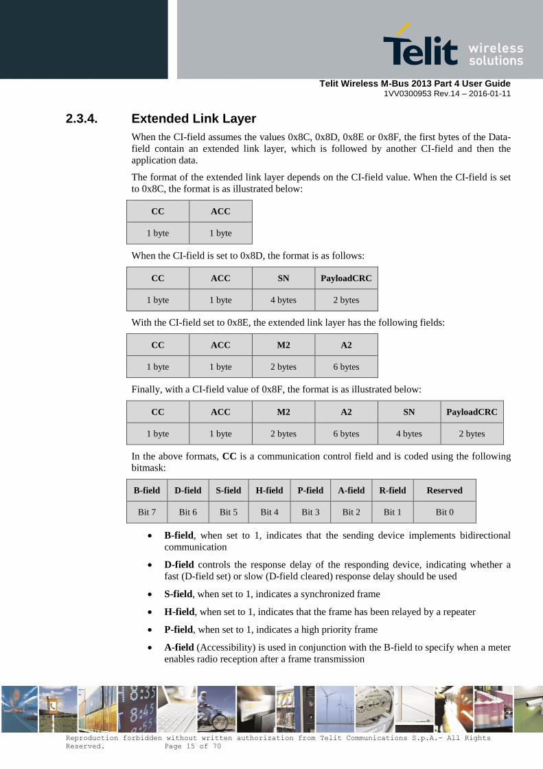
2.3.4. Extended Link Layer
When the CI-field assumes the values 0x8C, 0x8D, 0x8E or 0x8F, the first bytes of the Data-
field contain an extended link layer, which is followed by another CI-field and then the
application data.
The format of the extended link layer depends on the CI-field value. When the CI-field is set
to 0x8C, the format is as illustrated below:
CC ACC
1 byte 1 byte
When the CI-field is set to 0x8D, the format is as follows:
CC ACC SN PayloadCRC
1 byte 1 byte 4 bytes 2 bytes
With the CI-field set to 0x8E, the extended link layer has the following fields:
CC ACC M2 A2
1 byte 1 byte 2 bytes 6 bytes
Finally, with a CI-field value of 0x8F, the format is as illustrated below:
CC ACC M2 A2 SN PayloadCRC
1 byte 1 byte 2 bytes 6 bytes 4 bytes 2 bytes
In the above formats, CC is a communication control field and is coded using the following
bitmask:
B-field D-field S-field H-field P-field A-field R-field Reserved
Bit 7 Bit 6 Bit 5 Bit 4 Bit 3 Bit 2 Bit 1 Bit 0
B-field, when set to 1, indicates that the sending device implements bidirectional
communication
D-field controls the response delay of the responding device, indicating whether a
fast (D-field set) or slow (D-field cleared) response delay should be used
S-field, when set to 1, indicates a synchronized frame
H-field, when set to 1, indicates that the frame has been relayed by a repeater
P-field, when set to 1, indicates a high priority frame
A-field (Accessibility) is used in conjunction with the B-field to specify when a meter
enables radio reception after a frame transmission

Telit Wireless M-Bus 2013 Part 4 User Guide
1VV0300953 Rev.14 – 2016-01-11
Reproduction forbidden without written authorization from Telit Communications S.p.A.- All Rights
Reserved. Page 16 of 70
R-field (Repeated Access) is used by single hop repeaters according to the rules in
the EN 13757-5 specification
ACC is the access number and is used to detect duplicate frames and to associate request and
response frames.
SN (Session Number) is a 4 byte field (transmitted least significant byte first) with the
following content:
ENC-field Time-field Session-field
Bits 31 – 29 Bits 28 – 4 Bits 3 - 0
ENC-field specifies the encryption method, with the value 0 meaning no encryption
and the value 1 meaning AES-128 Counter Mode encryption; other values are
reserved for future use. If AES-128 Counter Mode is used, the remaining bytes of the
frame, from and including the PayloadCRC field (but excluding the CRC fields), will
be encrypted.
Time-field is a relative minute counter and is used together with the Session-field to
ensure that the encrypted transmission is protected from replay attacks
Session-field is a zero-based index of the communication session within the minute
specified by the Time-field
PayloadCRC is a cyclic redundancy check covering the remainder of the frame (excluding
the CRC fields).
M2 and A2 are used with CI-field values 0x8E and 0x8F, typically for transmissions from a
concentrator to a meter device, and indicate the Manufacturer Id and address of the
destination node of the frame. The format of the M2 and A2 fields is the same as that of the
M-field and the A-field, respectively.
2.3.5. Data Header
If the application layer defined by EN 13757-3 is used, depending on the value of the CI-field,
the first bytes of the Data-field may contain a data header as specified in this section. Two
types of data header (short and long) are defined. The short data header is present when the
CI-field assumes one of the following values: 0x5A, 0x61, 0x65, 0x6A, 0x6E, 0x74, 0x7A,
0x7B, 0x7D, 0x7F and 0x8A; it is formatted as illustrated below:
ACC STS Conf
1 byte 1 byte 2 bytes
The long data header is present when the CI-field has one of the values 0x5B, 0x60, 0x64,
0x6B, 0x6C, 0x6D, 0x6F, 0x72, 0x73, 0x75, 0x7C, 0x7E, 0x80, 0x84, 0x85 and 0x8B; it is
formatted as follows:
Identification
Number
Manufacturer
ID Version Device Type ACC STS Conf

Telit Wireless M-Bus 2013 Part 4 User Guide
1VV0300953 Rev.14 – 2016-01-11
Reproduction forbidden without written authorization from Telit Communications S.p.A.- All Rights
Reserved. Page 17 of 70
4 bytes 2 bytes 1 bytes 1 byte 1 byte 1 byte 2 bytes
Identification Number is a unique device identifier coded as 8 BCD digits.
Manufacturer ID is the identifier of the device manufacturer.
Version specifies the version number of the device.
Device Type specifies the functionality of the device (for example, electricity meter).
The set of Identification Number, Manufacturer ID, Version and Device Type fields
identify the Application Layer Address, which is used as described later in this section.
ACC is the access number and is used to detect duplicate frames and to associate request and
response frames.
STS is the status byte and its meaning depends on whether the frame is sent by a meter or a
concentrator.
Conf is the configuration word, whose primary purpose is to specify the encryption method
used to encrypt the frame.
Two encryption algorithms are defined in EN 13757-3:2012, namely DES and AES-128; for
both algorithms, Cipher Block Chaining (CBC) is used as mode of operation. Four different
encryption methods are identified by codes 2, 3, 4 and 5. Methods 2 and 3 use DES
encryption, while methods 4 and 5 use AES-128. Method 3 needs the long data header to
initialize the CBC algorithm, therefore it can be used only together with this header type; the
other methods can be used with either the short or long data header.
The P2 Companion Standard of Dutch Smart Meter Requirements defines an additional
encryption method (with code 15), which uses AES-128 with CBC. This method differs from
those defined in EN 13757-3 in that it requires a 32-bit frame counter to initialize the CBC
algorithm. The frame counter is transmitted unencrypted with least significant byte first, is
preceded by the fixed 3-byte header [0x04, 0xFD, 0x08] and is inserted at the end of the
encrypted frame.
The configuration word of the data header contains the length of encrypted content (in the
first byte) and the encryption method code (in the 4 least significant bits of the second byte).
Since encryption and decryption can only be performed in blocks, the number of encrypted
bytes is a multiple of the block size (8 for DES and 16 for AES-128). Therefore, the 3 or 4
least significant bits of the first byte of the configuration word do not enter in the count of
encrypted bytes, and can be used for other purposes.
The link layer header of Wireless M-Bus frames carries the manufacturer ID and address of
the sending device in the M-field and A-field, respectively, as described in Section 2.3.3; the
set of these two fields is referred to as Link Layer Address (LLA). In frames sent from
concentrators, additional fields are needed to identify the receiving meter; for this purpose,
the Application Layer Address (ALA) is used, as defined above in the long data header.
Please note that LLA and ALA differ in the relative position of their sub-fields: in the LLA
the manufacturer ID is the first sub-field, while in the ALA the manufacturer ID is inserted
between the identification number and the version code.

Telit Wireless M-Bus 2013 Part 4 User Guide
1VV0300953 Rev.14 – 2016-01-11
Reproduction forbidden without written authorization from Telit Communications S.p.A.- All Rights
Reserved. Page 18 of 70
3. Software Operation
The module can operate in two different modes:
The configuration mode which allows to parameter the module. It is set through the
use of Hayes commands sent on the serial link.
The operating mode which is the functional mode for data transmission.
3.1. Configuration Mode
Hayes or 'AT' commands comply with Hayes protocol used in PSTN modem standards. This
‘AT’ protocol or Hayes mode is used to configure the modem parameters, based on the
following principles:
A data frame always begins with the two ASCII ’AT’ characters, standing for
‘ATtention’
Commands are coded over one or several characters and may include additional data
A given command always ends with a <CR> Carriage Return
A T Command Additional data <CR>
The only exception to this data-framing rule is the switching command from the
operating/communication mode to ‘AT Mode’. In this case only, the escape code (‘+++’)
must be started and followed by a silent time at least equal to the serial time out, and <AT>
and <CR> shall not be used.
Commands are parsed by the module only after <CR> is sent, except for the escape
sequence ‘+++’ which is acted upon when the serial timeout expires after the last
character of the sequence.
Below is the complete list of the ‘AT’ commands available on the module.
Command Description
+++
‘+++’ command gives an instant access to the modem’s parameters
configuration mode (Hayes or AT mode), whatever the current
operating mode might be.
‘+++’ command should be entered as one string, i.e. it should not be
preceded by ‘AT’ and followed by <CR> but two silent times whose
duration is configurable via register 431 (Serial time-out). The time
between two ‘+’ characters must not exceed the time-out value.
Hayes mode inactivates radio functions.
Answer : OK
ATO
‘ATO’ command gives an instant access to the modem’s operating
mode, configured in register 400.
‘ATO’ command is used to get out of Hayes mode.
Answer : OK
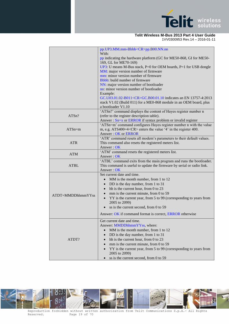
AT/V ‘AT/V’ command displays the modem’s firmware and bootloader
version number as follows:
Telit Wireless M-Bus 2013 Part 4 User Guide
1VV0300953 Rev.14 – 2016-01-11
Reproduction forbidden without written authorization from Telit Communications S.p.A.- All Rights
Reserved. Page 19 of 70
pp.UP3.MM.mm-Bbbb<CR>pp.B00.NN.nn
With:
pp indicating the hardware platform (GC for ME50-868, GI for ME50-
169, GL for ME70-169)
UP3: U means M-Bus stack, P=0 for OEM boards, P=1 for USB dongle
MM: major version number of firmware
mm: minor version number of firmware
Bbbb: build number of firmware
NN: major version number of bootloader
nn: minor version number of bootloader
Example:
GC.U03.01.02-B011<CR>GC.B00.01.10 indicates an EN 13757-4:2013
stack V1.02 (Build 011) for a ME0-868 module in an OEM board, plus
a bootloader V1.10
ATSn?
‘ATSn?’ command displays the content of Hayes register number n
(refer to the register description table).
Answer : Sn=x or ERROR if syntax problem or invalid register
ATSn=m
‘ATSn=m’ command configures Hayes register number n with the value
m, e.g. ATS400=4<CR> enters the value ‘4’ in the register 400.
Answer : OK or ERROR
ATR
‘ATR’ command resets all modem’s parameters to their default values.
This command also resets the registered meters list.
Answer : OK
ATM ‘ATM’ command resets the registered meters list.
Answer : OK
ATBL
‘ATBL’ command exits from the main program and runs the bootloader.
This command is useful to update the firmware by serial or radio link.
Answer : OK
ATDT=MMDDhhmmYYss
Set current date and time.
MM is the month number, from 1 to 12
DD is the day number, from 1 to 31
hh is the current hour, from 0 to 23
mm is the current minute, from 0 to 59
YY is the current year, from 5 to 99 (corresponding to years from
2005 to 2099)
ss is the current second, from 0 to 59
Answer: OK if command format is correct, ERROR otherwise
ATDT?
Get current date and time.
Answer: MMDDhhmmYYss, where:
MM is the month number, from 1 to 12
DD is the day number, from 1 to 31
hh is the current hour, from 0 to 23
mm is the current minute, from 0 to 59
YY is the current year, from 5 to 99 (corresponding to years from
2005 to 2099)
ss is the current second, from 0 to 59

Telit Wireless M-Bus 2013 Part 4 User Guide
1VV0300953 Rev.14 – 2016-01-11
Reproduction forbidden without written authorization from Telit Communications S.p.A.- All Rights
Reserved. Page 20 of 70
Specific ‘AT’ commands have been integrated in order to make measurements and tests.
ATT
Continuous modulated carrier, simulating transmission of ‘01’ data (or
‘0111’ data if 4GFSK modulation is used in Mode N).
Answer : OK
This command is stopped by sending a character on the serial link
Answer: No answer when exiting ATT.
ATT0
Pure carrier transmission at center frequency
Answer : OK
This command is stopped by sending a character on the serial link
Answer: No answer when exiting ATT0
This command is only available for ME50-169 and ME70-169.
ATT1
Continuous modulated carrier, simulating transmission of ‘01110010’
data if 4GFSK modulation is used in Mode N. Other modulations
simulate transmission of ‘01’ data.
Answer : OK
This command is stopped by sending a character on the serial link
Answer: No answer when exiting ATT1
This command is only available for ME50-169 and ME70-169.
ATT2 This command works just the same as the ATT command.
This command is only available for ME50-169 and ME70-169.
ATT3
Continuous modulated carrier, simulating transmission of random data.
Answer : OK
This command is stopped by sending a character on the serial link
Answer: No answer when exiting ATT3
This command is only available for ME50-169 and ME70-169.
After an AT command (ended by <CR>), the serial link gives back result code, “OK” or
“ERROR”; the response string contains <CR> as trailing character.
“+++” command gives back “OK”.
Telit Wireless M-Bus 2013 Part 4 User Guide
1VV0300953 Rev.14 – 2016-01-11
Reproduction forbidden without written authorization from Telit Communications S.p.A.- All Rights
Reserved. Page 21 of 70
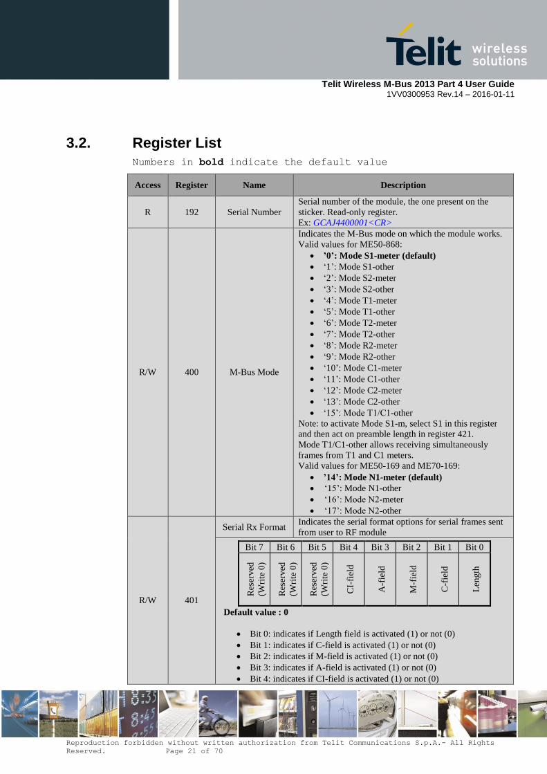
3.2. Register List Numbers in bold indicate the default value
Access Register Name Description
R 192 Serial Number
Serial number of the module, the one present on the
sticker. Read-only register.
Ex: GCAJ4400001<CR>
R/W 400 M-Bus Mode
Indicates the M-Bus mode on which the module works.
Valid values for ME50-868:
’0’: Mode S1-meter (default)
‘1’: Mode S1-other
‘2’: Mode S2-meter
‘3’: Mode S2-other
‘4’: Mode T1-meter
‘5’: Mode T1-other
‘6’: Mode T2-meter
‘7’: Mode T2-other
‘8’: Mode R2-meter
‘9’: Mode R2-other
‘10’: Mode C1-meter
‘11’: Mode C1-other
‘12’: Mode C2-meter
‘13’: Mode C2-other
‘15’: Mode T1/C1-other
Note: to activate Mode S1-m, select S1 in this register
and then act on preamble length in register 421.
Mode T1/C1-other allows receiving simultaneously
frames from T1 and C1 meters.
Valid values for ME50-169 and ME70-169:
’14’: Mode N1-meter (default)
‘15’: Mode N1-other
‘16’: Mode N2-meter
‘17’: Mode N2-other
R/W 401
Serial Rx Format Indicates the serial format options for serial frames sent
from user to RF module
Default value : 0
Bit 0: indicates if Length field is activated (1) or not (0)
Bit 1: indicates if C-field is activated (1) or not (0)
Bit 2: indicates if M-field is activated (1) or not (0)
Bit 3: indicates if A-field is activated (1) or not (0)
Bit 4: indicates if CI-field is activated (1) or not (0)
Bit 7 Bit 6 Bit 5 Bit 4 Bit 3 Bit 2 Bit 1 Bit 0
Res
erv
ed
(Wri
te 0
)
Res
erv
ed
(Wri
te 0
)
Res
erv
ed
(Wri
te 0
)
CI-
fiel
d
A-f
ield
M-f
ield
C-f
ield
Len
gth
Telit Wireless M-Bus 2013 Part 4 User Guide
1VV0300953 Rev.14 – 2016-01-11
Reproduction forbidden without written authorization from Telit Communications S.p.A.- All Rights
Reserved. Page 22 of 70
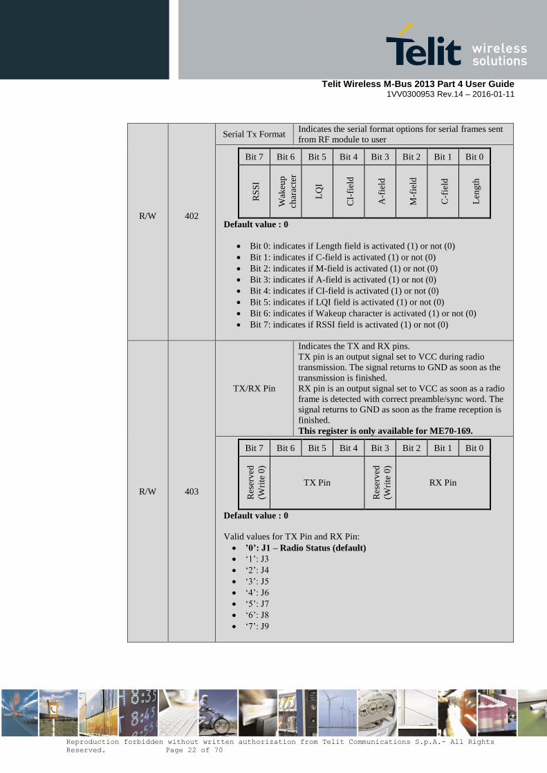
R/W
402
Serial Tx Format Indicates the serial format options for serial frames sent
from RF module to user
Default value : 0
Bit 0: indicates if Length field is activated (1) or not (0)
Bit 1: indicates if C-field is activated (1) or not (0)
Bit 2: indicates if M-field is activated (1) or not (0)
Bit 3: indicates if A-field is activated (1) or not (0)
Bit 4: indicates if CI-field is activated (1) or not (0)
Bit 5: indicates if LQI field is activated (1) or not (0)
Bit 6: indicates if Wakeup character is activated (1) or not (0)
Bit 7: indicates if RSSI field is activated (1) or not (0)
Bit 7 Bit 6 Bit 5 Bit 4 Bit 3 Bit 2 Bit 1 Bit 0
RS
SI
Wak
eup
char
acte
r
LQ
I
CI-
fiel
d
A-f
ield
M-f
ield
C-f
ield
Len
gth
R/W 403
TX/RX Pin
Indicates the TX and RX pins.
TX pin is an output signal set to VCC during radio
transmission. The signal returns to GND as soon as the
transmission is finished.
RX pin is an output signal set to VCC as soon as a radio
frame is detected with correct preamble/sync word. The
signal returns to GND as soon as the frame reception is
finished.
This register is only available for ME70-169.
Default value : 0
Valid values for TX Pin and RX Pin:
’0’: J1 – Radio Status (default)
‘1’: J3
‘2’: J4
‘3’: J5
‘4’: J6
‘5’: J7
‘6’: J8
‘7’: J9
Bit 7 Bit 6 Bit 5 Bit 4 Bit 3 Bit 2 Bit 1 Bit 0
Res
erv
ed
(Wri
te 0
)
TX Pin
Res
erv
ed
(Wri
te 0
)
RX Pin
Telit Wireless M-Bus 2013 Part 4 User Guide
1VV0300953 Rev.14 – 2016-01-11
Reproduction forbidden without written authorization from Telit Communications S.p.A.- All Rights
Reserved. Page 23 of 70
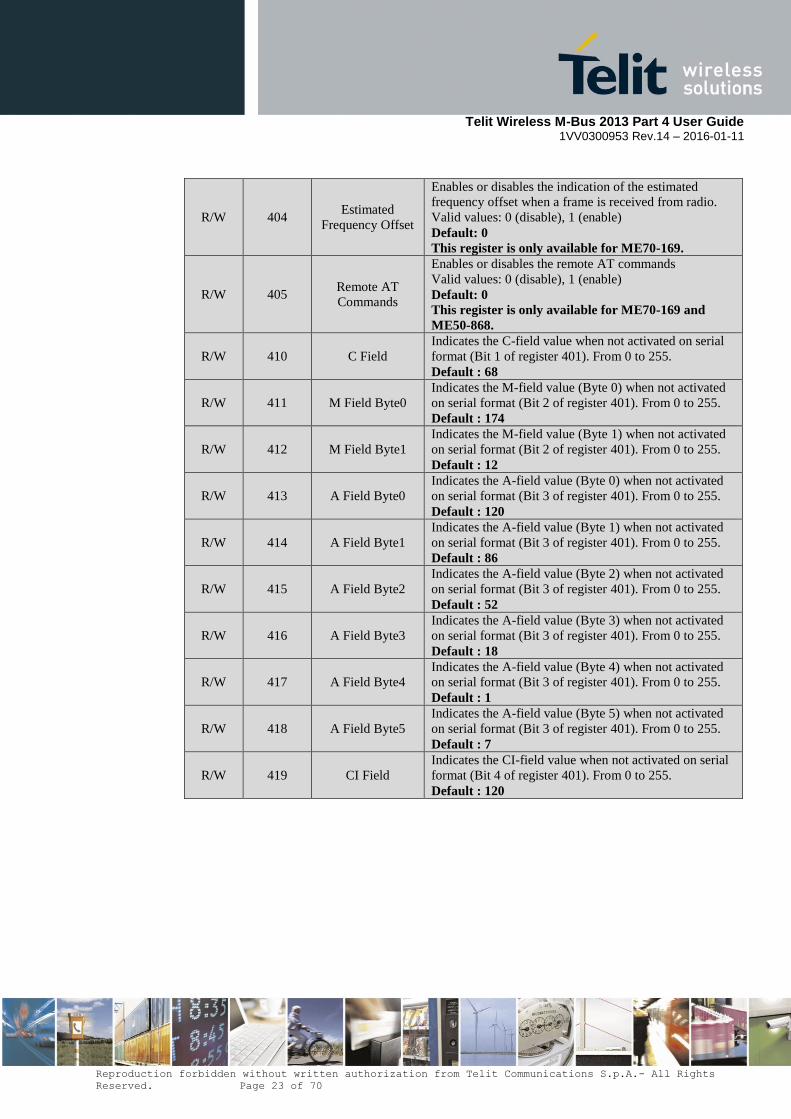
R/W 404 Estimated
Frequency Offset
Enables or disables the indication of the estimated
frequency offset when a frame is received from radio.
Valid values: 0 (disable), 1 (enable)
Default: 0
This register is only available for ME70-169.
R/W 405 Remote AT
Commands
Enables or disables the remote AT commands
Valid values: 0 (disable), 1 (enable)
Default: 0
This register is only available for ME70-169 and
ME50-868.
R/W 410 C Field
Indicates the C-field value when not activated on serial
format (Bit 1 of register 401). From 0 to 255.
Default : 68
R/W 411 M Field Byte0
Indicates the M-field value (Byte 0) when not activated
on serial format (Bit 2 of register 401). From 0 to 255.
Default : 174
R/W 412 M Field Byte1
Indicates the M-field value (Byte 1) when not activated
on serial format (Bit 2 of register 401). From 0 to 255.
Default : 12
R/W 413 A Field Byte0
Indicates the A-field value (Byte 0) when not activated
on serial format (Bit 3 of register 401). From 0 to 255.
Default : 120
R/W 414 A Field Byte1
Indicates the A-field value (Byte 1) when not activated
on serial format (Bit 3 of register 401). From 0 to 255.
Default : 86
R/W 415 A Field Byte2
Indicates the A-field value (Byte 2) when not activated
on serial format (Bit 3 of register 401). From 0 to 255.
Default : 52
R/W 416 A Field Byte3
Indicates the A-field value (Byte 3) when not activated
on serial format (Bit 3 of register 401). From 0 to 255.
Default : 18
R/W 417 A Field Byte4
Indicates the A-field value (Byte 4) when not activated
on serial format (Bit 3 of register 401). From 0 to 255.
Default : 1
R/W 418 A Field Byte5
Indicates the A-field value (Byte 5) when not activated
on serial format (Bit 3 of register 401). From 0 to 255.
Default : 7
R/W 419 CI Field
Indicates the CI-field value when not activated on serial
format (Bit 4 of register 401). From 0 to 255.
Default : 120
Telit Wireless M-Bus 2013 Part 4 User Guide
1VV0300953 Rev.14 – 2016-01-11
Reproduction forbidden without written authorization from Telit Communications S.p.A.- All Rights
Reserved. Page 24 of 70
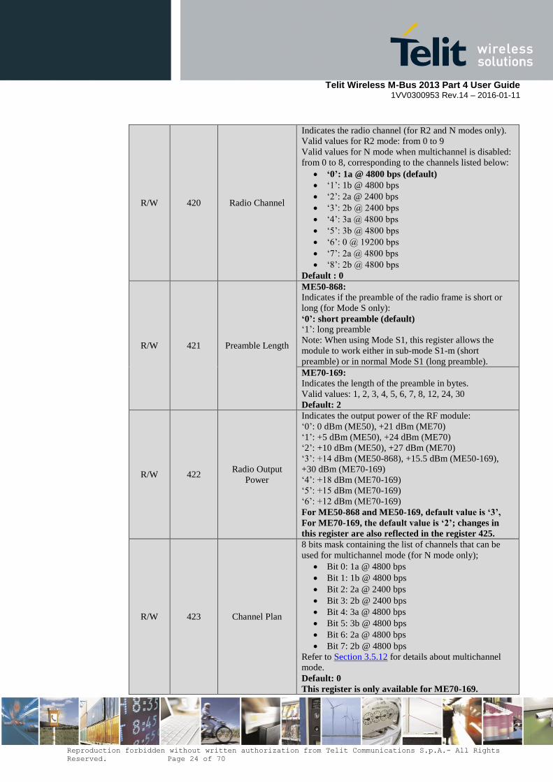
R/W 420 Radio Channel
Indicates the radio channel (for R2 and N modes only).
Valid values for R2 mode: from 0 to 9
Valid values for N mode when multichannel is disabled:
from 0 to 8, corresponding to the channels listed below:
‘0’: 1a @ 4800 bps (default)
‘1’: 1b @ 4800 bps
‘2’: 2a @ 2400 bps
‘3’: 2b @ 2400 bps
‘4’: 3a @ 4800 bps
‘5’: 3b @ 4800 bps
‘6’: 0 @ 19200 bps
‘7’: 2a @ 4800 bps
‘8’: 2b @ 4800 bps
Default : 0
R/W 421 Preamble Length
ME50-868:
Indicates if the preamble of the radio frame is short or
long (for Mode S only):
‘0’: short preamble (default)
‘1’: long preamble
Note: When using Mode S1, this register allows the
module to work either in sub-mode S1-m (short
preamble) or in normal Mode S1 (long preamble).
ME70-169:
Indicates the length of the preamble in bytes.
Valid values: 1, 2, 3, 4, 5, 6, 7, 8, 12, 24, 30
Default: 2
R/W 422 Radio Output
Power
Indicates the output power of the RF module:
‘0’: 0 dBm (ME50), +21 dBm (ME70)
‘1’: +5 dBm (ME50), +24 dBm (ME70)
‘2’: +10 dBm (ME50), +27 dBm (ME70)
‘3’: +14 dBm (ME50-868), +15.5 dBm (ME50-169),
+30 dBm (ME70-169)
‘4’: +18 dBm (ME70-169)
‘5’: +15 dBm (ME70-169)
‘6’: +12 dBm (ME70-169)
For ME50-868 and ME50-169, default value is ‘3’,
For ME70-169, the default value is ‘2’; changes in
this register are also reflected in the register 425.
R/W 423 Channel Plan
8 bits mask containing the list of channels that can be
used for multichannel mode (for N mode only);
Bit 0: 1a @ 4800 bps
Bit 1: 1b @ 4800 bps
Bit 2: 2a @ 2400 bps
Bit 3: 2b @ 2400 bps
Bit 4: 3a @ 4800 bps
Bit 5: 3b @ 4800 bps
Bit 6: 2a @ 4800 bps
Bit 7: 2b @ 4800 bps
Refer to Section 3.5.12 for details about multichannel
mode.
Default: 0
This register is only available for ME70-169.

Telit Wireless M-Bus 2013 Part 4 User Guide
1VV0300953 Rev.14 – 2016-01-11
Reproduction forbidden without written authorization from Telit Communications S.p.A.- All Rights
Reserved. Page 25 of 70
R 424 Current Channel
Indicates the current channel (useful when multichannel
mode is enabled, for N mode only):
‘0’: 1a @ 4800 bps
‘1’: 1b @ 4800 bps
‘2’: 2a @ 2400 bps
‘3’: 2b @ 2400 bps
‘4’: 3a @ 4800 bps
‘5’: 3b @ 4800 bps
‘6’: 0 @ 19200 bps
‘7’: 2a @ 4800 bps
‘8’: 2b @ 4800 bps
Refer to Section 3.5.12 for details about multichannel
mode.
This register is only available for ME70-169.
R/W 425 Radio Output
Power dBm
Indicates the output power of the RF module expressed
in dBm:
Valid values: 12, 15, 18, 21, 24, 27, 30 (dBm)
Default: 27
This register is only available for ME70-169; changes
in this register are also reflected in the register 422.
R/W 426 Set Frequency
Offset
Indicates the offset compared to the nominal frequency,
expressed in ppm, in order to change the central
frequency in TX and RX.
Valid values: from -128 to 127 (ppm)
Default: 0
This register is only available for ME70-169.
R/W 427 Preamble Word
Indicates the preamble byte configuration (for Mode N
only):
‘0’: 0x55 (default)
‘1’: 0xAA
This register is only available for ME50-169 and
ME70-169.
R/W 428 Postamble Length
Indicates the length of the postamble in bytes.
Valid values: from 0 to 10
Default: 0
This register is only available for ME70-169.
R/W 429
TX Datarate for
Mode T
Meter to Other
Indicates the datarate in kbps for mode T1-meter and
mode T2-meter.
Valid values: from 90 to 110 (kbps)
Default: 103
This register is only available for ME50-868
R/W 430 Serial Speed
Indicates the speed on the serial link :
‘1’: 1200 bits/s
‘2’: 2400 bits/s
‘3’: 4800 bits/s
‘4’: 9600 bits/s
‘5’: 19200 bits/s (default)
‘6’: 38400 bits/s
‘7’: 57600 bits/s
‘8’: 115200 bits/s
Telit Wireless M-Bus 2013 Part 4 User Guide
1VV0300953 Rev.14 – 2016-01-11
Reproduction forbidden without written authorization from Telit Communications S.p.A.- All Rights
Reserved. Page 26 of 70
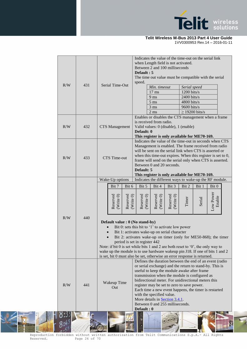
R/W 431 Serial Time-Out
Indicates the value of the time-out on the serial link
when Length field is not activated.
Between 2 and 100 milliseconds
Default : 5
The time out value must be compatible with the serial
speed.
Min. timeout Serial speed
17 ms 1200 bits/s
9 ms 2400 bits/s
5 ms 4800 bits/s
3 ms 9600 bits/s
2 ms ≥ 19200 bits/s
R/W 432 CTS Management
Enables or disables the CTS management when a frame
is received from radio.
Valid values: 0 (disable), 1 (enable)
Default: 0
This register is only available for ME70-169.
R/W 433 CTS Time-out
Indicates the value of the time-out in seconds when CTS
Management is enabled. The frame received from radio
will be sent on the serial link when CTS is asserted or
when this time-out expires. When this register is set to 0,
frame will send on the serial only when CTS is asserted.
Between 0 and 20 seconds.
Default: 5
This register is only available for ME70-169.
R/W 440
Wake-Up options Indicates the different ways to wake-up the RF module.
Default value : 0 (No stand-by)
Bit 0: sets this bit to ‘1’ to activate low power
Bit 1: activates wake-up on serial character
Bit 2: activates wake-up on timer (only for ME50-868); the timer
period is set in register 442
Note: if bit 0 is set while bits 1 and 2 are both reset to ‘0’, the only way to
wake up the module is to use hardware wakeup pin J18. If one of bits 1 and 2
is set, bit 0 must also be set, otherwise an error response is returned.
Bit 7 Bit 6 Bit 5 Bit 4 Bit 3 Bit 2 Bit 1 Bit 0
Res
erv
ed
(Wri
te 0
)
Res
erv
ed
(Wri
te 0
)
Res
erv
ed
(Wri
te 0
)
Res
erv
ed
(Wri
te 0
)
Res
erv
ed
(Wri
te 0
)
Tim
er
Ser
ial
Lo
w P
ow
er
En
able
R/W 441 Wakeup Time
Out
Defines the duration between the end of an event (radio
or serial exchange) and the return to stand-by. This is
useful to keep the module awake after frame
transmission when the module is configured as
bidirectional meter. For unidirectional meters this
register may be set to zero to save power.
Each time a new event happens, the timer is restarted
with the specified value.
More details in Section 3.4.1.
Between 0 and 255 milliseconds.
Default : 0

Telit Wireless M-Bus 2013 Part 4 User Guide
1VV0300953 Rev.14 – 2016-01-11
Reproduction forbidden without written authorization from Telit Communications S.p.A.- All Rights
Reserved. Page 27 of 70
R/W 442 Sleep Time
Defines sleep time in seconds between 2 wake-up events
when wake-up timer option is activated in register 440.
Between 0 and 255.
0 indicates a sleep duration of 500 milliseconds.
Other values indicate directly the sleep duration in
seconds.
Default : 1
This register is only available for ME50-868.
R/W 452 Rx Filter
8 bits mask indicating whether received radio frames are
filtered based on their M-field and A-field.
Enables/disables reception of multicast and broadcast
frames (ME70-169). More details in Section 3.5.6.
Bit 0: enables Rx filter
Bit 1: enables multicast when Rx filter is enabled
(only for ME70-169)
Bit 2: enables broadcast when Rx filter is
enabled (only for ME70-169)
Bit 3-7: reserved
Default : 0
R/W 453 Tx Options
8 bits mask containing options for Wireless M-Bus
frame transmission.
Bit 0: reserved
Bit 1: enables Listen Before Talk
Bit 2: enables frame format B (only for Modes C
and N)
Bit 3: enables automatic frame transmission
Bit 4: enables synchronized frame transmission
Bit 5: enables multi-frame operation
Bit 6: enables serial acknowledge
Bit 7: enables immediate tx serial frame (only for
ME70-169 and ME50-868)
Refer to Section 3.5 for details on transmission options.
Default: 0
R/W 454 Repeater
Enables or disables repeater operation in Mode S or T.
Refer to Section 3.5.11 for details on repeater
functionality.
Valid values: 0 (disable), 1 (enable)
Default: 0
This register is only available for ME50-868.
Telit Wireless M-Bus 2013 Part 4 User Guide
1VV0300953 Rev.14 – 2016-01-11
Reproduction forbidden without written authorization from Telit Communications S.p.A.- All Rights
Reserved. Page 28 of 70
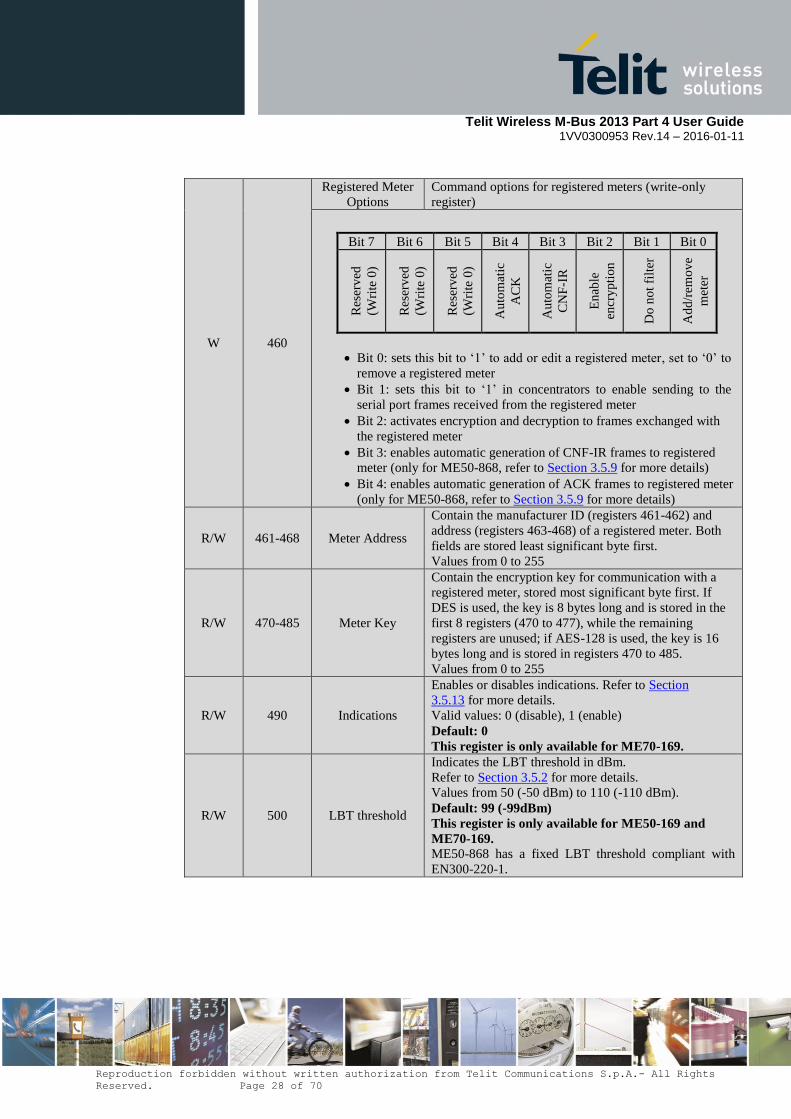
W 460
Registered Meter
Options
Command options for registered meters (write-only
register)
Bit 0: sets this bit to ‘1’ to add or edit a registered meter, set to ‘0’ to
remove a registered meter
Bit 1: sets this bit to ‘1’ in concentrators to enable sending to the
serial port frames received from the registered meter
Bit 2: activates encryption and decryption to frames exchanged with
the registered meter
Bit 3: enables automatic generation of CNF-IR frames to registered
meter (only for ME50-868, refer to Section 3.5.9 for more details)
Bit 4: enables automatic generation of ACK frames to registered meter
(only for ME50-868, refer to Section 3.5.9 for more details)
Bit 7 Bit 6 Bit 5 Bit 4 Bit 3 Bit 2 Bit 1 Bit 0
Res
erv
ed
(Wri
te 0
)
Res
erv
ed
(Wri
te 0
)
Res
erv
ed
(Wri
te 0
)
Au
tom
atic
AC
K
Au
tom
atic
CN
F-I
R
En
able
encr
yp
tion
Do
no
t fi
lter
Ad
d/r
emo
ve
met
er
R/W 461-468 Meter Address
Contain the manufacturer ID (registers 461-462) and
address (registers 463-468) of a registered meter. Both
fields are stored least significant byte first.
Values from 0 to 255
R/W 470-485 Meter Key
Contain the encryption key for communication with a
registered meter, stored most significant byte first. If
DES is used, the key is 8 bytes long and is stored in the
first 8 registers (470 to 477), while the remaining
registers are unused; if AES-128 is used, the key is 16
bytes long and is stored in registers 470 to 485.
Values from 0 to 255
R/W 490 Indications
Enables or disables indications. Refer to Section
3.5.13 for more details.
Valid values: 0 (disable), 1 (enable)
Default: 0
This register is only available for ME70-169.
R/W 500 LBT threshold
Indicates the LBT threshold in dBm.
Refer to Section 3.5.2 for more details.
Values from 50 (-50 dBm) to 110 (-110 dBm).
Default: 99 (-99dBm)
This register is only available for ME50-169 and
ME70-169.
ME50-868 has a fixed LBT threshold compliant with
EN300-220-1.
Telit Wireless M-Bus 2013 Part 4 User Guide
1VV0300953 Rev.14 – 2016-01-11
Reproduction forbidden without written authorization from Telit Communications S.p.A.- All Rights
Reserved. Page 29 of 70
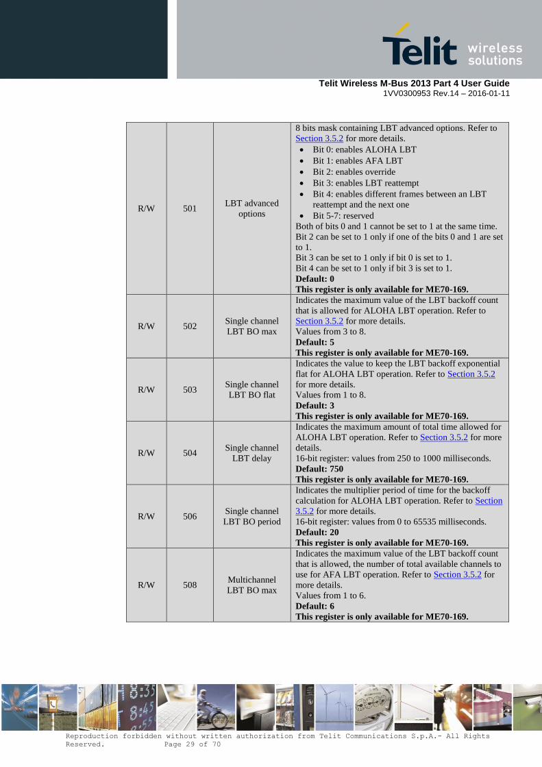
R/W 501 LBT advanced
options
8 bits mask containing LBT advanced options. Refer to
Section 3.5.2 for more details.
Bit 0: enables ALOHA LBT
Bit 1: enables AFA LBT
Bit 2: enables override
Bit 3: enables LBT reattempt
Bit 4: enables different frames between an LBT
reattempt and the next one
Bit 5-7: reserved
Both of bits 0 and 1 cannot be set to 1 at the same time.
Bit 2 can be set to 1 only if one of the bits 0 and 1 are set
to 1.
Bit 3 can be set to 1 only if bit 0 is set to 1.
Bit 4 can be set to 1 only if bit 3 is set to 1.
Default: 0
This register is only available for ME70-169.
R/W 502 Single channel
LBT BO max
Indicates the maximum value of the LBT backoff count
that is allowed for ALOHA LBT operation. Refer to
Section 3.5.2 for more details.
Values from 3 to 8.
Default: 5
This register is only available for ME70-169.
R/W 503 Single channel
LBT BO flat
Indicates the value to keep the LBT backoff exponential
flat for ALOHA LBT operation. Refer to Section 3.5.2
for more details.
Values from 1 to 8.
Default: 3
This register is only available for ME70-169.
R/W 504 Single channel
LBT delay
Indicates the maximum amount of total time allowed for
ALOHA LBT operation. Refer to Section 3.5.2 for more
details.
16-bit register: values from 250 to 1000 milliseconds.
Default: 750
This register is only available for ME70-169.
R/W 506 Single channel
LBT BO period
Indicates the multiplier period of time for the backoff
calculation for ALOHA LBT operation. Refer to Section
3.5.2 for more details.
16-bit register: values from 0 to 65535 milliseconds.
Default: 20
This register is only available for ME70-169.
R/W 508 Multichannel
LBT BO max
Indicates the maximum value of the LBT backoff count
that is allowed, the number of total available channels to
use for AFA LBT operation. Refer to Section 3.5.2 for
more details.
Values from 1 to 6.
Default: 6
This register is only available for ME70-169.
Telit Wireless M-Bus 2013 Part 4 User Guide
1VV0300953 Rev.14 – 2016-01-11
Reproduction forbidden without written authorization from Telit Communications S.p.A.- All Rights
Reserved. Page 30 of 70
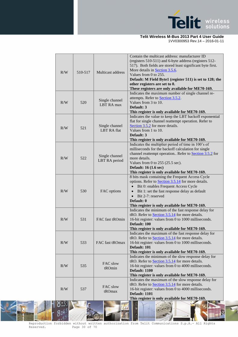
R/W 510-517 Multicast address
Contain the multicast address: manufacturer ID
(registers 510-511) and 6-byte address (registers 512-
517). Both fields are stored least significant byte first.
More details in Section 3.5.6.
Values from 0 to 255.
Default: M Field Byte1 (register 511) is set to 128; the
other registers are set to 0.
These registers are only available for ME70-169.
R/W 520 Single channel
LBT RA max
Indicates the maximum number of single channel re-
attempts. Refer to Section 3.5.2.
Values from 3 to 10.
Default: 3
This register is only available for ME70-169.
R/W 521 Single channel
LBT RA flat
Indicates the value to keep the LBT backoff exponential
flat for single channel reattempt operation. Refer to
Section 3.5.2 for more details.
Values from 1 to 10.
Default: 3
This register is only available for ME70-169.
R/W 522 Single channel
LBT RA period
Indicates the multiplier period of time in 100’s of
milliseconds for the backoff calculation for single
channel reattempt operation.. Refer to Section 3.5.2 for
more details.
Values from 0 to 255 (25.5 sec).
Default: 16 (1.6 sec)
This register is only available for ME70-169.
R/W 530 FAC options
8 bits mask containing the Frequent Access Cycle
options. Refer to Section 3.5.14 for more details.
Bit 0: enables Frequent Access Cycle
Bit 1: set the fast response delay as default
Bit 2-7: reserved
Default: 0
This register is only available for ME70-169.
R/W 531 FAC fast tROmin
Indicates the minimum of the fast response delay for
tRO. Refer to Section 3.5.14 for more details.
16-bit register: values from 0 to 1000 milliseconds.
Default: 100
This register is only available for ME70-169.
R/W 533 FAC fast tROmax
Indicates the maximum of the fast response delay for
tRO. Refer to Section 3.5.14 for more details.
16-bit register: values from 0 to 1000 milliseconds.
Default: 101
This register is only available for ME70-169.
R/W 535 FAC slow
tROmin
Indicates the minimum of the slow response delay for
tRO. Refer to Section 3.5.14 for more details.
16-bit register: values from 0 to 4000 milliseconds.
Default: 1100
This register is only available for ME70-169.
R/W 537 FAC slow
tROmax
Indicates the maximum of the slow response delay for
tRO. Refer to Section 3.5.14 for more details.
16-bit register: values from 0 to 4000 milliseconds.
Default: 1101
This register is only available for ME70-169.

Telit Wireless M-Bus 2013 Part 4 User Guide
1VV0300953 Rev.14 – 2016-01-11
Reproduction forbidden without written authorization from Telit Communications S.p.A.- All Rights
Reserved. Page 31 of 70
R/W 539 FAC txD
Indicates the transmission delay for FAC. Refer to
Section 3.5.14 for more details.
Values from 1 to 15 seconds.
Default: 5
This register is only available for ME70-169.
R/W 540 FAC timeout
Indicates the timeout for FAC. Refer to Section 3.5.14
for more details.
Values from 20 to 255 seconds.
Default: 30
This register is only available for ME70-169.
3.3. Operating Mode
When the module is in operating mode, each frame arriving on the serial link is sent on the
radio link, and each valid Wireless M-Bus frame received on the radio link is sent on the
serial link. These rules do not apply when repeater operation is enabled; refer to Section
3.5.11 for information on repeater operation. If indications are enabled, serial frame has an
additional header to distinguish MBUS frames from indications; refer to Section 3.5.13 for
more details.
Data transmitted or received over the serial port will have a specific format depending on the
module configuration defined through the different registers. It allows a high flexibility in the
use of the module in a Wireless M-Bus application.
A module configured as unidirectional meter (register 400 set to 0, 4, 10 or 14) does not
activate frame reception on the radio interface. As a result, no frames will be sent to the serial
link by modules with these configuration settings.
3.3.1. Serial Frame on Transmission
Serial frames arriving on the serial link of the RF module can have the following fields:
Wakeup Length C M A CI Data
with:
Field Length Description
Wakeup 1
Wakeup character
If wakeup on serial character is activated, the RF module can be triggered by
starting the serial frame with a 0xFF or 0x00 character.
RF Module User

Telit Wireless M-Bus 2013 Part 4 User Guide
1VV0300953 Rev.14 – 2016-01-11
Reproduction forbidden without written authorization from Telit Communications S.p.A.- All Rights
Reserved. Page 32 of 70
Length 1
Length of frame Giving the serial frame length to the RF module shortcuts the serial time out
at the end of RX, leading in a very short wake up duration and very low
power results. Using this field allows to save at least 2 ms for each wake up
cycle. The RF module considers that the serial frame is complete as soon as
the specified length is reached.
Length value should count all subsequent bytes, including other serial
options fields if any. Only Wake-up and Length bytes don’t enter in the
calculation of Length.
C 1 C-field
It specifies the role of the frame (Request, ACK …).
M 2 Manufacturer ID and Address fields Use this option to simplify the maintenance: in case of radio module
replacement, the ID is already specified in the host and doesn’t need to be set
through registers.
However this option makes the serial frame longer and increases the work
duration (more power consumption). M and A can be activated separately.
A 6
CI 1
Control Information field.
Option to be used if several applicative layers use the wireless M-Bus link. If
only one application is running, the CI-field can be fixed and specified in the
corresponding register.
Data Variable Data field.
User application data; its minimum length is 0 bytes and its maximum length
is 245 for frame format A and 241 for frame format B.
The optional header depends on the different settings of module registers:
Wakeup is necessary if bit 1 of register 440 is set to 1
Length is necessary if bit 0 of register 401 is set to 1
C is necessary if bit 1 of register 401 is set to 1
M is necessary if bit 2 of register 401 is set to 1
A is necessary if bit 3 of register 401 is set to 1
CI is necessary if bit 4 of register 401 is set to 1
When the Length field is activated in the serial Rx format options, if the value of the
field received by the module is outside the range of values allowed to build a valid data
frame, the received byte is discarded.
When automatic frame transmission and multi-frame operation are enabled, the serial
frame has an additional field: the command byte, which is inserted as the first byte of
the serial frame (after the wakeup character, if enabled). Refer to Section 3.5.9 for more
details.
When indications are enabled in ME70-169, the serial frame has an additional field: the
header-data byte, which is inserted as the first byte of the serial frame (after the wakeup
character, if enabled). When automatic frame transmission, multi-frame operation and
indications are enabled, only the command byte is inserted as the first byte of the serial
frame (after the wakeup character, if enabled). Refer to Section 3.5.13 for more details.

Telit Wireless M-Bus 2013 Part 4 User Guide
1VV0300953 Rev.14 – 2016-01-11
Reproduction forbidden without written authorization from Telit Communications S.p.A.- All Rights
Reserved. Page 33 of 70
Examples:
S401 = 31 and S440 = 3 or 7
Serial frame must have this format:
Wakeup Length C M A CI Data
S401 = 30 and S440 = 3 or 7
Serial frame must have this format:
Wakeup C M A CI Data
S401 = 17 and S440 = 3 or 7
Serial frame must have this format:
Wakeup Length CI Data
S401 = 31 and S440 = 1 or 5
Serial frame must have this format:
Length C M A CI Data
Whatever is the serial frame format, data on RF link will always have the same format,
described in Section 2.4. In case of one or several fields (except Wakeup) is not activated on
the serial frame, the RF module will use the value defined in the corresponding register.
Example:
If serial frame has this format:
Length Data (10 bytes)
On the RF link, the frame will have the following format (assuming frame format A is used):
Preamble
L-field C-field M-field A-field CRC-field

Telit Wireless M-Bus 2013 Part 4 User Guide
1VV0300953 Rev.14 – 2016-01-11
Reproduction forbidden without written authorization from Telit Communications S.p.A.- All Rights
Reserved. Page 34 of 70
Length Register 410 Registers 411 - 412 Registers 413 - 418 2 bytes
CI-field Data-field CRC-field
Register 419 Data (10 bytes) 2 bytes
Postamble
3.3.2. Serial Frame on Reception
Serial frames sent on the serial link by the RF module can have the following fields:
0xFF Length C M A CI Data LQI RSSI FreqOffset
with:
Field Length Description
0xFF 1
Wakeup character
Very useful especially in Mode R2 to work as “Wake On Radio” way.
With this character the user can be woken up by serial if a valid radio
frame is received. This option comes in addition to the STANDBY
STATUS signal.
Length 1
Length of frame Indicates to the user the length of serial frame he is receiving. Length
value takes into account the subsequent bytes, including other serial
options fields if any, but excluding LQI and RSSI fields.
C 1 C-field Specifies the role of the frame (Request, ACK, ...).
M 2 Manufacturer ID and Address fields Indicate the M-field and A-field of the received frame. M and A can be
activated separately. A 6
CI 1 Control Information field. Option to be used if several applicative layers use the wireless M-Bus
link.
Data Variable Data field.
User application data; its minimum length is 0 bytes and its maximum
length is 245 for frame format A and 241 for frame format B.
LQI 1 LQI This byte indicates the level of radio reception, from 0 (poor) to 3
(excellent).
RF Module User

Telit Wireless M-Bus 2013 Part 4 User Guide
1VV0300953 Rev.14 – 2016-01-11
Reproduction forbidden without written authorization from Telit Communications S.p.A.- All Rights
Reserved. Page 35 of 70
RSSI 1 RSSI Received Signal Strength Indicator, containing the input power of the
received radio frame expressed in dBm as a signed 8 bit number.
FreqOffset 1
Estimated Frequency Offset (only for ME70-169)
This byte indicates the estimated frequency offset of the received signal
compared to the module frequency, expressed in ppm as a signed 8 bit
number.
The optional header and footer depend on the different settings of module registers:
Wake-up will be added if bit 6 of register 402 is set to 1
Length will be added if bit 0 of register 402 is set to 1
C will be added if bit 1 of register 402 is set to 1
M will be added if bit 2 of register 402 is set to 1
A will be added if bit 3 of register 402 is set to 1
CI will be added if bit 4 of register 402 is set to 1
LQI will be added if bit 5 of register 402 is set to 1
RSSI will be added if bit 7 of register 402 is set to 1
FreqOffset will be added if register 404 is set to 1 (only for ME70-169)
If automatic frame transmission with multi-frame operation and serial acknowledge is
enabled (i.e., the module is configured as concentrator and bits 3, 5 and 6 of register 453
are set), an additional header byte with value 0x00 is transmitted by the module before
the serial frame (after the wakeup character if enabled). This header byte is needed in
order to distinguish serial frames from serial acknowledge messages. Refer to Section
3.5.9 for additional information on the serial acknowledge option.
When indications are enabled in ME70-169, the serial frame has an additional field: the
header-data byte, which is inserted as the first byte of the serial frame (after the wakeup
character, if enabled). If automatic frame transmission, multi-frame operation, serial
acknowledge and indications are enabled, only one additional header byte with value
0x00 is transmitted by the module before the serial frame (after the wakeup character if
enabled); if an indication is received on the serial link, only one additional header byte
with value 0xFF is transmitted by the module. Refer to Section 3.5.13 for more details.
Examples:
S402 = 127
Serial frame will have this format:
Wakeup Length C M A CI Data LQI
S402 = 126

Telit Wireless M-Bus 2013 Part 4 User Guide
1VV0300953 Rev.14 – 2016-01-11
Reproduction forbidden without written authorization from Telit Communications S.p.A.- All Rights
Reserved. Page 36 of 70
Serial frame will have this format:
Wakeup C M A CI Data LQI
S402 = 209
Serial frame will have this format:
Wakeup Length CI Data RSSI
S402 = 31
Serial frame will have this format:
Length C M A CI Data
3.4. Stand-by Mode
A key functionality available into the Wireless M-Bus stack is the ability to have RF modules
in stand-by mode. During this mode, the RF module has very low power consumption. Stand-
by mode is not activated when repeater operation is enabled (refer to Section 3.5.11): in this
case, the configuration options set in register 440 do not have effect and the module remains
always active.
3.4.1. Wakeup of the Module
There are 3 different ways to wake up the module, defined by value of register 440.
Wakeup on hardware, using wakeup signal J18: it is always possible to wake up the
module by applying a logical ‘1’ to the ‘WAKEUP’ signal. When serial transmission is
finished, ‘WAKEUP’ signal must be put back to a logical ‘0’ to allow the module
returning in stand-by; else the module is kept awake while the WAKEUP pin is
maintained to ‘1’. When wakeup on serial character is not activated, there must be at
least a 90 µs delay between the positive edge of the WAKEUP pin and the first character
sent on the serial port.
Wakeup on serial character: it is possible to wake up the module by sending a wakeup
character at the beginning of the serial frame to send (refer to Section 3.3.1); although
any character can awaken the module, either 0xFF or 0x00 must be used as wakeup
character, otherwise the module serial port might receive corrupted bytes. After sending
this frame on the air, the module will stay awake until a new radio or serial event occurs
or until timeout defined by register 441 is reached.
Wakeup on timer (only for ME50-868): it is possible to force the module to wake up
periodically. This cyclic wakeup option is activated by bit 2 of register 440 and the time
between two wakeup events is defined by the value of register 442. When waking up, the
module will check the radio link for a valid frame preamble. If nothing is detected on the

Telit Wireless M-Bus 2013 Part 4 User Guide
1VV0300953 Rev.14 – 2016-01-11
Reproduction forbidden without written authorization from Telit Communications S.p.A.- All Rights
Reserved. Page 37 of 70
air, the module returns immediately to stand-by. Otherwise, it will wait for a valid frame
and then automatically go back to stand-by after an interval defined by the value of
register 441.
When the wakeup timeout defined by register 441 expires, if a radio frame reception is
ongoing, the module does not enter stand-by mode but waits for the incoming frame to be
received. Frame reception is considered to be initiated when the preamble has been received
(refer to Sections 2.3.1 and 2.3.2 for more information on frame preamble). If a device
expects to receive a frame within a defined time interval, the wakeup timeout of the module
should be set to a value higher than the expected delay of the beginning of the frame, to take
into account preamble transmission. The duration of frame preamble for a given mode can be
calculated from the bit rate value (reported in Section 2.2) and the preamble length.
When timer is enabled, the stand-by consumption of the RF module is higher (refer to
consumption data in refer to the user guides of the modules).
3.4.2. Wakeup of External User Equipment
There are 2 different ways to wake up the external user equipment:
Through ‘STANDBY STATUS’ output signal (J2): this signal is set to logical ‘1’ while
the module is operating and returns to ‘0’ during stand-by periods.
Through serial character: when the module receives a valid RF frame, it can add a 0xFF
character at the beginning of the serial frame to wake up the external user equipment.
This type of functioning is so called “Wake on Radio”.
3.5. Advanced Features
3.5.1. Hardware Flow Control
In both configuration mode and data mode, flow control on the serial port is operated via the
RTS pin, which is de-asserted (logic level 1) when the module is unable to receive bytes (e.g.
when processing an AT command or a serial frame) and re-asserted (logic level 0) when new
bytes can be received.
For ME70-169: when configuration register 432 is set to 1, the CTS pin is checked after a
frame is received from radio and before sending it on the serial link. If CTS is de-asserted,
only one frame is stored (the oldest one). CTS management does not apply to indications and
during a Frequent Access Cycle.
3.5.2. Listen Before Talk
When bit 1 of configuration register 453 is set to 1, the Listen Before Talk (LBT) feature of
the module is enabled. LBT operation allows decreasing the probability of collision between
different modules trying to transmit radio frames at the same time. When this feature is
enabled, the module listens to the wireless medium before transmitting a radio frame.

Telit Wireless M-Bus 2013 Part 4 User Guide
1VV0300953 Rev.14 – 2016-01-11
Reproduction forbidden without written authorization from Telit Communications S.p.A.- All Rights
Reserved. Page 38 of 70
LBT threshold is configurable for ME50-169 and ME70-169 using configuration register 500,
whereas ME50-868 has a fixed LBT threshold compliant with EN300-220-1.
Four LBT modes are available.
3.5.2.1. Basic LBT
When bit 1 of configuration register 453 is set to 1 and bit 0 and 1 of configuration register
501 are set to 0, basic LBT is enabled.
The minimum listen time is 5 ms; if during this time no activity is detected on the radio link,
frame transmission starts immediately, otherwise the module waits until the link becomes free
and then listens again for another 5 ms interval, after which an additional listen interval of
random duration between 0 and 5 ms is added before frame transmission finally starts. If the
radio link becomes busy during the listen time, the module waits for the channel to become
free and then restarts the listen procedure.
3.5.2.2. ALOHA LBT (ME70-169)
When bit 1 of configuration register 453 is set to 1 and bit 0 and 1 of configuration register
501 are set to 1 and 0 respectively, ALOHA LBT is enabled. ALOHA LBT parameters can be
set using configuration registers 502-506.
The single channel ALOHA LBT access uses an exponentially increasing random time
backoff with a limited allowed time delay. If the channel is clear then the module transmits
the frame, else if the channel is not clear the module performs a random backoff in time and
then re-assesses the channel. The random backoff is exponentially increasing. The module
shall attempt this for a number of LBT tries or for an overall delay time limit. If the number of
tries is exceeded or the delay time limit is exceeded then the module determines if it is
allowed to transmit the frame or not in a LBT override (bit 2 of configuration register 501).
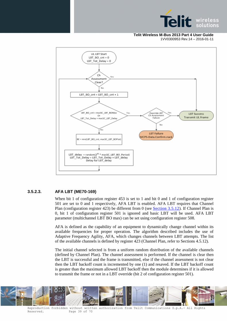
Telit Wireless M-Bus 2013 Part 4 User Guide
1VV0300953 Rev.14 – 2016-01-11
Reproduction forbidden without written authorization from Telit Communications S.p.A.- All Rights
Reserved. Page 39 of 70
3.5.2.3. AFA LBT (ME70-169)
When bit 1 of configuration register 453 is set to 1 and bit 0 and 1 of configuration register
501 are set to 0 and 1 respectively, AFA LBT is enabled. AFA LBT requires that Channel
Plan (configuration register 423) be different from 0 (see Section 3.5.12). If Channel Plan is
0, bit 1 of configuration register 501 is ignored and basic LBT will be used. AFA LBT
parameter (multichannel LBT BO max) can be set using configuration register 508.
AFA is defined as the capability of an equipment to dynamically change channel within its
available frequencies for proper operation. The algorithm described includes the use of
Adaptive Frequency Agility, AFA, which changes channels between LBT attempts. The list
of the available channels is defined by register 423 (Channel Plan, refer to Sections 4.5.12).
The initial channel selected is from a uniform random distribution of the available channels
(defined by Channel Plan). The channel assessment is performed. If the channel is clear then
the LBT is successful and the frame is transmitted, else if the channel assessment is not clear
then the LBT backoff count is incremented by one (1) and resaved. If the LBT backoff count
is greater than the maximum allowed LBT backoff then the module determines if it is allowed
to transmit the frame or not in a LBT override (bit 2 of configuration register 501).
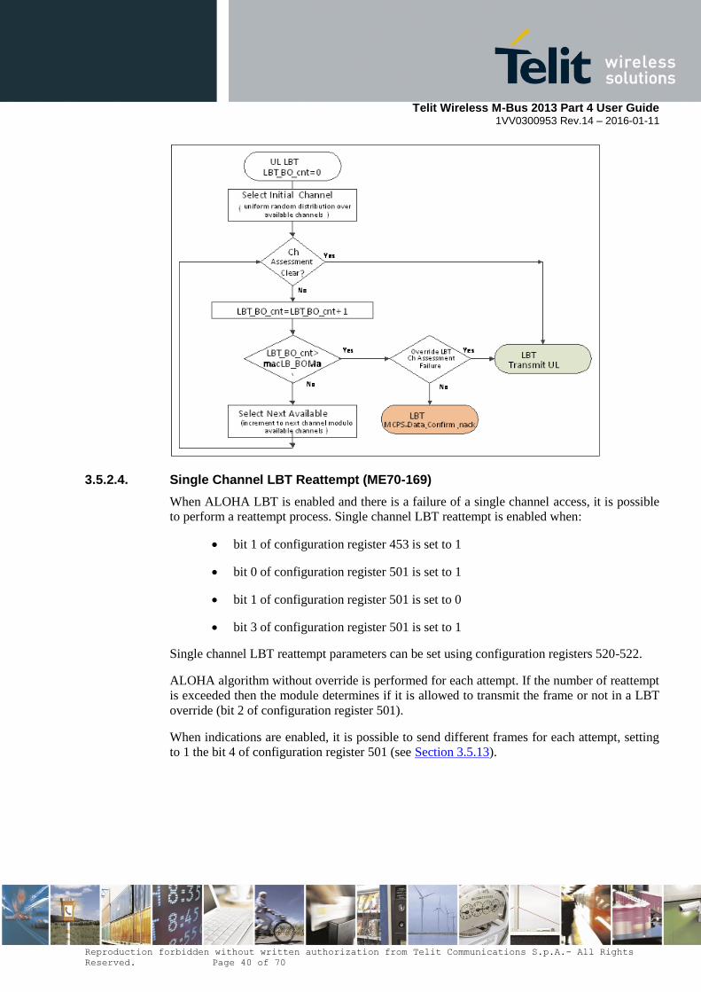
Telit Wireless M-Bus 2013 Part 4 User Guide
1VV0300953 Rev.14 – 2016-01-11
Reproduction forbidden without written authorization from Telit Communications S.p.A.- All Rights
Reserved. Page 40 of 70
3.5.2.4. Single Channel LBT Reattempt (ME70-169)
When ALOHA LBT is enabled and there is a failure of a single channel access, it is possible
to perform a reattempt process. Single channel LBT reattempt is enabled when:
bit 1 of configuration register 453 is set to 1
bit 0 of configuration register 501 is set to 1
bit 1 of configuration register 501 is set to 0
bit 3 of configuration register 501 is set to 1
Single channel LBT reattempt parameters can be set using configuration registers 520-522.
ALOHA algorithm without override is performed for each attempt. If the number of reattempt
is exceeded then the module determines if it is allowed to transmit the frame or not in a LBT
override (bit 2 of configuration register 501).
When indications are enabled, it is possible to send different frames for each attempt, setting
to 1 the bit 4 of configuration register 501 (see Section 3.5.13).
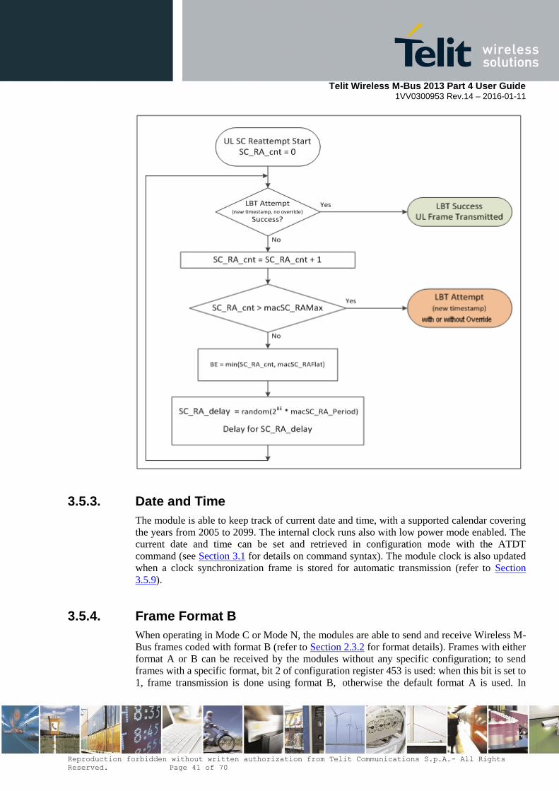
Telit Wireless M-Bus 2013 Part 4 User Guide
1VV0300953 Rev.14 – 2016-01-11
Reproduction forbidden without written authorization from Telit Communications S.p.A.- All Rights
Reserved. Page 41 of 70
3.5.3. Date and Time
The module is able to keep track of current date and time, with a supported calendar covering
the years from 2005 to 2099. The internal clock runs also with low power mode enabled. The
current date and time can be set and retrieved in configuration mode with the ATDT
command (see Section 3.1 for details on command syntax). The module clock is also updated
when a clock synchronization frame is stored for automatic transmission (refer to Section
3.5.9).
3.5.4. Frame Format B
When operating in Mode C or Mode N, the modules are able to send and receive Wireless M-
Bus frames coded with format B (refer to Section 2.3.2 for format details). Frames with either
format A or B can be received by the modules without any specific configuration; to send
frames with a specific format, bit 2 of configuration register 453 is used: when this bit is set to
1, frame transmission is done using format B, otherwise the default format A is used. In

Telit Wireless M-Bus 2013 Part 4 User Guide
1VV0300953 Rev.14 – 2016-01-11
Reproduction forbidden without written authorization from Telit Communications S.p.A.- All Rights
Reserved. Page 42 of 70
ME50-868, bit 2 of register 453 can be set to 1 only when the module is configured to operate
in Mode C.
3.5.5. Registered Meters
A module can register up to 32 or 64 meters, to be used for filtering received M-Bus frames,
encrypting radio communication, or generating automatic messages. Data for registered
meters is stored in EEPROM memory, which is accessed through configuration registers 460,
461-468 and 470-485. ME50-868 and ME50-169 modules have a limit of 32 registered
meters, while ME70-169 can register up to 64 meters.
To add, edit or delete an entry in the list of registered meters, the manufacturer ID and address
of the meter must be inserted in registers 461 to 468, the encryption key (if used) must be
inserted in registers 470 to 485, and the appropriate flags must be set in register 460. When bit
0 of register 460 is set to 1, if no meter corresponding to the contents of registers 461 to 468 is
present in the list, a new entry is added with the option flags specified in register 460; if the
meter is already present, no entry is added, but the option flags of the existing entry are
updated. When bit 0 of register 460 is set to 0, the registered meter corresponding to the
contents of registers 461 to 468, if present in the list, is unregistered. An error response is
returned by the module when trying to add a new entry if the list is full. Register 460 is write-
only, and an error response is returned when trying to read the register value. After exiting
configuration mode, contents of registers 461 to 468 and 470 to 485 are not guaranteed to
remain the same when re-entering configuration mode, thus the user should always set the
register contents (at least manufacturer ID and address, if no encryption is needed) before
setting a value in register 460. Issuing the ATR or ATM command clears the list of registered
meters. Refer to Sections 3.5.8, 3.5.9 and 3.5.10 for details on how to use registered meters
and their option flags.
3.5.6. Frame Filtering
An optional filter on received M-Bus frames can be activated, which allows transmitting to
the serial port only frames whose meter manufacturer ID and address match one or more
specific values. If an Application Layer Address is present in a received frame, the meter
manufacturer ID and address are taken from those fields, otherwise the Link Layer Address is
used to identify the meter; refer to Section 2.3 for details on the address formats. Frame
filtering is enabled by setting bit 0 of register 452 to 1. The addresses used to filter incoming
frames differ depending on whether the module is configured as ‘meter’ or ‘other’ device.
Meter devices use the manufacturer ID and address defined by the content of registers 411 to
418 to filter incoming frames; this applies to unicast frames. In order to enable also the
reception of multicast and broadcast frames to a meter, respectively bit 1and bit 2 of register
452 must be set to 1 (only for ME70-169).
Multicast frames use a soft address in place of meter address. This soft address, that defines a
group of meters, is assigned to module using the content of registers 510 to 517.

Telit Wireless M-Bus 2013 Part 4 User Guide
1VV0300953 Rev.14 – 2016-01-11
Reproduction forbidden without written authorization from Telit Communications S.p.A.- All Rights
Reserved. Page 43 of 70
Broadcast frames are distinguished by:
C-field with PRM bit set to 1 and function code set to 3 (refer to Section 2.3.3 for a
description of C-field format)
CI-field set to 0x5A, 0x61 or 0x65 (data frames with short transport layer, no
destination address)
Concentrators can use the frame filtering feature of the module by registering the meters from
which they want to receive data, i.e. putting their manufacturer ID and address in the list of
registered meters. When registering a given meter (or changing the options of a registered
meter), bit 1 in the value of register 460 must be set to 1 in order to enable sending to the
serial port M-Bus frames received from that meter.
A Wireless M-Bus application can define an installation mode in which a meter looks for a
concentrator to bind to. Frames sent by meters in installation mode use typically a C-field
with function code set to 6 (refer to Section 2.3.3 for a description of C-field format). In order
to be able to receive frames from meters in installation mode, when the module is configured
to act as concentrator, filtering does not apply to received frames in which the C-field has the
PRM bit set to 1 and the function code set to 6: these frames are sent to the serial port
regardless of the frame filtering option.
These are the possible configurations of register 452:
Concentrator - Bit 0 set to 0: concentrator sends on the serial link to the host all the
received radio frames; no filtering is performed.
Concentrator - Bit 0 set to 1: concentrator sends on the serial link to the host the
unicast frames coming only from its registered meters and all the installation radio
frames.
Meter - Bit 0 set to 0: meter sends on the serial link to the host all the received radio
frames; no filtering is performed.
Meter - Bit 0 set to 1, bits 1 and 2 set to 0: meter sends on the serial link to the host
only the unicast radio frames addressed to it.
Meter - Bits 0 and 1set to 1, bit 2 set to 0: meter sends on the serial link to the host the
the unicast radio frames addressed to it and also the multicast radio frames with its
destination soft address.
Meter - Bits 0 and 2 set to 1, bit 1 set to 0: meter sends on the serial link to the host
the unicast radio frames addressed to it and also the broadcast radio frames.
Meter - Bit 0, 1 and 2 set to 1: meter sends on the serial link to the host the unicast
radio frames addressed to it, the multicast radio frames with its destination soft
address and the broadcast radio frames.

Telit Wireless M-Bus 2013 Part 4 User Guide
1VV0300953 Rev.14 – 2016-01-11
Reproduction forbidden without written authorization from Telit Communications S.p.A.- All Rights
Reserved. Page 44 of 70
3.5.7. Encryption
The module can encrypt and decrypt Wireless M-Bus frames to provide secure
communication between nodes. Both DES and AES-128 encryption algorithms as defined in
EN 13757-3:2012 are supported, as well as AES-128 with Counter Mode as defined in EN
13757-4:2013.
In order to use encrypted communication, frames sent by the user application must contain
either an extended link layer containing the Session Number field with a valid encryption
method (refer to Section 2.3.4), or a data header as defined in Section 2.3.5. Depending on the
contents of the frame, the module encrypts or decrypts it with the appropriate method.
The encryption methods defined in EN 13757-3 are identified by codes 2, 3, 4 and 5. Method
3 needs the current date to initialize the CBC algorithm, therefore in order to communicate
with this encryption method a meter must have the same date as set in the concentrator.
Beside the methods defined in EN 13757-3, the module supports method 15 defined in the
Dutch Smart Meter Requirements. Refer to Section 2.3.5 for more details on the different
encryption methods.
Concentrator devices can send encrypted frames to (and receive encrypted frames from) any
of the registered meters; to enable encryption for communication with a given meter,
manufacturer ID, address and key (DES or AES-128) of the meter must be inserted in the
relevant registers and bit 2 must be set to 1 in the option register 460. A meter device must
insert its own manufacturer ID, address and key in an entry of the registered meter list and set
bit 2 of register 460. The manufacturer ID and address of the meter in a given frame are taken
from the Link Layer Address if the CI-field of the frame does not indicate a long data header,
otherwise they are taken from the Application Layer Address.
Once all the relevant configuration registers for encryption have been set, when a frame with
an extended link layer or a data header specifying one of the supported encryption methods is
received from the serial port, the module encrypts the frame using the key corresponding to
the meter manufacturer ID and address and the given encryption method. If method 15 is
used, the user application must insert a frame counter and its header at the end of the serial
frame, as described in Section 2.3.5. If the encryption methods is incompatible with the CI-
field, or if method 15 is specified but the frame counter and its header are not present at the
end of the data field, the frame is discarded. If the encryption method is not supported (or is 0,
which means no encryption), the frame is sent unencrypted. Before encrypting a frame, if
CBC is used (as defined in EN 13757-3) filler bytes with value 0x2F are added at the end of
the Data-field, if necessary, to make the length of the encrypted payload a multiple of the
block size (8 bytes for DES and 16 bytes for AES-128); if filler bytes cannot be added
because the maximum frame length has been reached, the frame is discarded. If encryption
method 15 is used, when filler bytes are added to the frame to be encrypted, the frame counter
and its header are moved accordingly so that they are placed after the encrypted data. The
number of encrypted blocks contained in the configuration word provided by the user is
ignored, and the value corresponding to the length of the encrypted content is inserted in the
configuration word before sending the frame (sent frames cannot be partially encrypted).
When receiving from the radio interface an encrypted Wireless M-Bus frame, if the meter
address corresponds to a registered meter with encryption enabled, the module decrypts the
frame before sending it to the serial port, provided the frame contains a valid extended link
layer or data header and a supported encryption method code. Received frames that cannot
Telit Wireless M-Bus 2013 Part 4 User Guide
1VV0300953 Rev.14 – 2016-01-11
Reproduction forbidden without written authorization from Telit Communications S.p.A.- All Rights
Reserved. Page 45 of 70
be decrypted because of invalid contents (such as Data-field length incompatible with
configuration word, or encryption method incompatible with data header) are discarded, and
frames with unsupported encryption methods are sent unaltered to the serial port. Decryption
of partially encrypted frames is supported. The module does not modify the SN field or the
configuration word of a received M-Bus frame after decryption, so that user applications are
able to verify which encryption method has been used and how many blocks of the frame
have been sent encrypted.
3.5.8. Remote AT Commands
The module is able to accept and execute AT commands sent over the radio link as Wireless
M-Bus frames; this feature is particularly useful to update the firmware of the module from a
remote host. For ME70-169 and ME50-868, remote AT commands can be enabled using the
configuration register 405. For ME50-169 this feature is always enabled.
A Wireless M-Bus frame containing an AT command for a given module must have the C-
Field set to 0x4B and the CI-Field set to 0xA0 (this is the first value in the range reserved for
manufacturer-specific applications according to EN 13757-4); the first 8 bytes of the Data-
Field must contain the manufacturer Id and address of the module to which the command is
directed, corresponding to the contents of configuration registers 411 to 418 of the receiving
module. After the module identification, the Data-Field must contain the AT command with
the format described in Section 3.1, without the trailing <CR> character. Upon receiving a
remote AT command, the module, instead of sending the received frame to the serial port,
executes the command and replies with a Wireless M-Bus frame containing the response to
the command. The response frame has the C-Field set to 0x08 and the CI-Field set to 0xA0;
the first part of the Data-Field contains the manufacturer Id and address of the module which
sent the command frame, while the rest of the Data-Field contains the response with the
format described in Section 3.1, without the trailing <CR> character.
If the module receives a remote AT command including a <CR> character, this
character and all subsequent bytes in the command string are ignored.
The ‘+++’ escape sequence and the ATT command cannot be sent remotely, and an ERROR
response is sent by the module if these command strings are received. Since registers 461 to
468 and 470 to 485 are not guaranteed to keep their content when the module is in operating
mode, it is not recommended to use remote AT commands to update the list of registered
meters of a given module.
In order to avoid conflict with the execution of remote AT commands, external applications
should not use the CI-Field value 0xA0 for other purposes than sending AT commands.
3.5.9. Automatic frame transmission
In typical installations, meter devices are battery-powered, thus energy saving mechanisms
must be implemented in order to optimize battery consumption. The standard approach
prescribed in the EN 13757-4 specification for battery-operated meters is to enable the radio
receiver for a small amount of time after every frame transmission, and then disable radio
reception until the next frame transmission. If the meter receives a frame during the short
interval in which reception is activated, it enters the so-called Frequent Access Cycle (FAC),
during which it sends a frame every few seconds and then listens for a frame from the

Telit Wireless M-Bus 2013 Part 4 User Guide
1VV0300953 Rev.14 – 2016-01-11
Reproduction forbidden without written authorization from Telit Communications S.p.A.- All Rights
Reserved. Page 46 of 70
concentrator; the FAC allows the concentrator to communicate with meters with a short
latency. The FAC ends when either a specific frame (SND-NKE) is sent by the concentrator,
or the meter does not receive frames for a specified amount of time.
In order for a frame to be received by a meter operating with the above logic, the concentrator
must transmit the frame within a short time interval after the meter transmission. This
constraint is particularly severe in mode T, in which frame transmission by the concentrator
must start within 3 milliseconds after reception of the frame from the meter; since each frame
received and transmitted by the module must pass through the serial port in order to interact
with the user application, standard module operation might not be able to satisfy the timing
requirements of EN 13757-4. For this reason, a feature has been introduced which allows a
module configured as concentrator to automatically send frames to meters, based on specific
rules as described in the rest of this section.
When bit 3 of configuration register 453 is set to 1, a frame received on the serial port by a
module configured as concentrator is not sent immediately to the radio interface, but is stored
in the module memory to be sent when specific conditions are met, as described later in this
section. This stored frame can either refer to a specific destination meter, or be a generic
frame, based on the meter address; as always, the meter address is taken from the Application
Layer Address if the stored frame has a CI-field indicating the presence of a long data header,
otherwise it is taken from the Link Layer Address. The stored frame is a generic frame when
its meter address has a special value in which all bytes are set to 0xFF; generic frames are
used to let the module generate automatically the meter destination address based on frames
received from the radio interface. If multi-frame operation is enabled (bit 5 of configuration
register 453), it is possible to store in the module multiple frames, specifying the location of
each frame with the command byte (described next); otherwise, only one frame can be stored
in the module at a given time, and the serial frame does not include the command byte.
If multi-frame operation is enabled, the module internal memory dedicated to automatic frame
transmission is composed of 4 contiguous buffers of 256 bytes each, and each buffer is
divided in 4 slots of 64 bytes each. The user application assigns a given frame to a specific
slot via an additional field of the serial frame, called command byte, whose format is
described below.
Reserved CMD BufNo SlotNo
Bit 7 Bit 6 Bit 5 Bit 4 Bit 3 Bit 2 Bit 1 Bit 0
BufNo is the buffer number, with allowed values from 0 to 3
SlotNo is the slot number inside a given buffer, with allowed values from 0 to 3
CMD is the command field; the allowed values of this field are the following:
o 0: clear the memory, i.e. delete all stored frames
o 2: clear the buffer specified by BufNo, i.e. delete all stored frames in that
buffer
o 3: insert a frame in the slot SlotNo inside the buffer specified by BufNo
The reserved bit of the command byte must be set to 0. In order to insert a frame in a slot
inside a specific buffer, the command byte is sent with CMD set to 3 and BufNo and SlotNo
set to the desired values; after the command byte follows the frame with the usual format

Telit Wireless M-Bus 2013 Part 4 User Guide
1VV0300953 Rev.14 – 2016-01-11
Reproduction forbidden without written authorization from Telit Communications S.p.A.- All Rights
Reserved. Page 47 of 70
determined by the Serial Rx Format options (configuration register 401). If the wakeup
character is enabled in the options, the command byte must be sent after the wakeup character.
If the frame length (including all the frame contents from L-field to Data-field, but excluding
the CRC-fields) exceeds the slot size (64 bytes), the frame occupies also the next slots (up to
4 slots can be occupied by a single frame); for example, if a 150-byte frame is assigned to slot
number 3 of buffer 0, it occupies 3 consecutive slots: slot 3 of buffer 0 and slot 0 and slot 1 of
buffer 1. Any existing frames in the assigned slots will be overwritten by the new frame. If a
frame cannot be inserted in a series of consecutive slots, it is discarded by the module; for
example, it is not possible to insert a 100-byte frame in slot 3 of buffer 3, because the frame
occupies two slots and there is no next slot after the assigned slot 3 of buffer 3. With the
command byte it is possible to delete the stored frames, clearing either a single buffer, or the
entire memory area; if one of the delete commands is used, the command byte is not followed
by frame data.
When multi-frame operation is enabled, if bit 6 of configuration register 453 is set a serial
acknowledge message is sent by module after each command received from the serial port.
The acknowledge message contains the result of command execution and its format is
explained below:
Reserved Ack/Nack Type Command Byte
Bit 7 Bit 6 Bit 5 Bit 4 Bit 3 Bit 2 Bit 1 Bit 0 Bits 7 … 0
The first byte is a header with the following bit fields:
Type: identifies the message type. A value of 0b00 indicates a Wireless M-Bus
frame: in this case the message is not the reply to a command, does not contain the
command byte and is followed by the serial frame formatted according to the settings
of configuration register 402; if the wakeup character is enabled, it is sent before the
header byte. A value of 0b01 in the Type field indicates an acknowledgement
(positive or negative) to a received command: in this case the Ack/Nack field
contains the result of command execution. Other values for the Type field are
reserved.
Ack/Nack: when the Type field has the value 0b01, the Ack/Nack field contains the
result of command execution; defined values are:
o 0b000: command executed successfully
o 0b001: command not recognized
o 0b010: invalid buffer number
o 0b011: the frame cannot be stored because its length is incompatible with the
buffer and slot number
o 0b100: the stored frame cannot be encrypted because it contains invalid data;
refer to Section 3.5.7 for details on frame encryption
Reserved: reserved for future use, currently set to 0
The second byte of the acknowledge message is a copy of the command byte received by the
module and allows to associate a command with its corresponding acknowledge.
Telit Wireless M-Bus 2013 Part 4 User Guide
1VV0300953 Rev.14 – 2016-01-11
Reproduction forbidden without written authorization from Telit Communications S.p.A.- All Rights
Reserved. Page 48 of 70
Standard Wireless M-Bus frames sent by a meter should contain information on whether the
meter is able to receive a response frame from the concentrator. If the meter uses the extended
link layer, this information is carried in the B-field of the CC field (refer to Section 2.3.4),
which is set to 1 to indicate that the meter supports bi-directional communication. If no
extended link layer is present and a standard data header (Section 2.3.5) is used instead, and
the configuration word indicates an encryption method with one of the values 0, 4, 5, 6 and 15,
the most significant bit of the second byte of the configuration word indicates whether the
meter is able to receive frames: if this bit is set to 1, it means that the meter can receive
frames. When a module configured as concentrator receives a frame indicating that the
sending meter can receive a response, the module can automatically send a frame to the meter
based on the following rules:
If the received frame has a C-field with the PRM bit set to 1 and a function code set
to 6 (installation request), and the sending meter is a registered meter in the
concentrator module with bit 3 (automatic CNF-IR) of the option flags set to 1, the
concentrator automatically sends a response frame with the C-field set to 6 and a long
data header containing the meter address. This frame exchange is typically used at
installation time when the meter searches for a concentrator to bind to; the response
from the concentrator indicates that the concentrator accepts the installation request
from the meter.
If the received frame has a C-field with the PRM bit set to 1 and a function code set
to 8, and the sending meter is a registered meter in the concentrator module with bit 4
(automatic ACK) of the option flags set to 1, the concentrator automatically sends a
response frame with the C-field set to 0 and a long data header containing the meter
address. This frame exchange is typically used when the meter has data to transmit
and wants the concentrator to request this data; the concentrator response activates the
Frequent Access Cycle.
If the module in the concentrator has one or more stored frames with the meter
address either corresponding to the address of the sending meter, or with all bytes set
to 0xFF (generic frame), the concentrator sends automatically the first (starting from
slot number 0 in buffer number 0) of these stored frames, after replacing the 0xFF
bytes of the meter address with the address of the sending meter if the frame is a
generic frame.
In the above rules, if the CI-field of the frame sent by the meter indicates the presence of a
long data header the meter address is taken from the Application Layer Address, otherwise
the meter address is taken from the Link Layer Address.
If multi-frame operation is not enabled, a stored frame is kept in the module internal memory
(and possibly sent multiple times) until it is overwritten by another frame.
If multi-frame operation is enabled, a stored frame is not deleted from the internal memory
after being transmitted, but the module waits to receive from the meter a response frame (with
the PRM bit of the C-field set to 0) with the same access number as the stored frame: when
this frame is received, the stored frame transmitted previously is deleted from the module, and
the next frame (if any) stored for the meter is automatically transmitted. The access number is
taken from the Extended Link Layer (refer to Section 2.3.4) if present, otherwise it is taken
from the Data Header (described in Section 2.3.5); if no access number field is present in a
stored frame, the frame is deleted immediately after transmission. Also, the stored frame is
deleted immediately if it has a C-field with the PRM bit set to 1 and the function field set to
0x00, because this type of frame (called SND-NKE) is used by the concentrator to end the
Telit Wireless M-Bus 2013 Part 4 User Guide
1VV0300953 Rev.14 – 2016-01-11
Reproduction forbidden without written authorization from Telit Communications S.p.A.- All Rights
Reserved. Page 49 of 70
Frequent Access Cycle of a meter and there is no corresponding response frame from the
meter. The same mechanism applies to generic frames, i.e. frames whose meter address has
all bytes set to 0xFF: after transmitting a generic frame, the frame is kept in the module
memory (unless it is a SND-NKE or does not have an access number) until a response frame
with the same access number is received from any meter.
The automatic frame transmission mechanism allows to store in the module frames that will
be sent at a later time, typically when the destination meter wakes up. If a stored frame
contains a clock synchronization command, the date and time information in the frame might
be outdated when the frame is sent by the module. For this reason, the module is able to
update automatically the date and time information in clock synchronization frames before
sending them to the destination meters. When the automatic frame transmission is enabled, if
a frame with a CI-field set to 0x6C (clock synchronization frame containing a date and time
setting) is stored in the module, the module parses the frame contents and, if valid, uses the
date and time information in the frame to synchronize its own clock; before transmitting the
stored frame, the module changes the date and time settings of the frame with an up-to-date
timestamp taken from its own clock. Refer to the European standard EN 13747-3 for
information on the format to be used for clock synchronization frames.
When a stored frame is automatically sent by the concentrator, it is encrypted as described in
Section 3.5.8 if the destination meter is a registered meter with encryption enabled. In case of
a generic frame, the encryption must be carried out after determining the address of the
sending meter; since AES-128 encryption is a computationally intensive process, if more than
four 16-byte blocks have to be encrypted in a generic frame, the module is unable to satisfy
the timing requirement of Mode T. For this reason, if frames with more than 4 encrypted
blocks have to be automatically transmitted in Mode T, it is recommended to use stored
frames with a specific meter address, because in this case frame encryption can be performed
as soon as the frame is received from the serial port. The same limitation applies when the
extended link layer is used with AES-128 Counter Mode encryption, because the encryption
algorithm needs a frame number which is known only after the concentrator receives the
frame from the meter.
3.5.10. Synchronized frame transmission
Bit 4 of configuration register 453 allows controlling the timing of frames sent by the
concentrator. If this bit is cleared, every frame to be sent to the radio interface is sent as soon
as the module is ready to send it, after the internal processing done by the firmware (such as
encryption and CRC calculation). If this bit is set to 1, the module sends frames after a
specific delay from the last received frame; this feature is useful to ensure that the
concentrator response to a frame sent by a meter satisfies the requirements on minimum
response delay prescribed by EN 13757-4.
The minimum response delay values used by the module for the different modes are taken
from the EN 13757-4 specification and are listed below:
Mode S: 3 ms
Mode T: 2 ms
Mode R2: 10 ms
Telit Wireless M-Bus 2013 Part 4 User Guide
1VV0300953 Rev.14 – 2016-01-11
Reproduction forbidden without written authorization from Telit Communications S.p.A.- All Rights
Reserved. Page 50 of 70
Mode C: the delay value depends on the contents of the frame received from the
meter: if the frame contains an extended link layer, the D-field of the CC byte (refer
to Section 2.3.4) indicates whether a fast (90 ms) or slow (1000 ms) response delay
should be used; if no extended link layer is present, by default a fast response delay is
used.
Mode N: the delay value depends on the contents of the frame received from the
meter: if the frame contains an extended link layer, the D-field of the CC byte (refer
to Section 2.3.4) indicates whether a fast or slow response delay should be used; if no
extended link layer is present, the default response delay is used.
o ME50-169: 100 ms for the fast response delay; 1100 ms for the slow
response delay. The default response delay (fast or slow) can be chosen using
the bit 1 in the configuration register 530.
o ME70-169: the delay value depends on the contents of the registers 531 (fast
response) and 535 (slow response). The default response delay (fast or slow)
can be chosen using the bit 1 in the configuration register 530.
Synchronized frame transmission can be used together with the automatic frame transmission
mechanism described in the previous section; in this case, automatic frames are sent by the
concentrator after the minimum response delay defined for the different modes.
For ME70-169 and ME50-868, bit 7 of configuration register 453 allows controlling when the
frames received from radio are sent on the serial link if automatic and synchronized frames
are enabled; if bit 7 is set to 1, when any frame is received from radio, it is immediately sent
on the serial link; if bit 7 is set to 0, the frame received from radio is sent on the serial link
only after the transmission of the automatic frame (ME50-169 always has this last behaviour).
If synchronized transmission is used without automatic transmission, when a frame is
received from the serial port the module checks if the minimum delay value has passed since
the last received frame, and if necessary the module waits for this delay to pass before
transmitting the frame.
3.5.11. Repeater operation
The Open Metering System Specification defines the functionality of repeater devices, used to
extend the communication range between meters and concentrators. These devices are
unidirectional repeaters, which receive frames sent by meters and forward them toward the
concentrator; the use of such repeaters is limited to modes S and T.
ME50-868 modules can provide autonomous repeater functionality according to the OMS
specification. This feature is enabled when configuration register 454 is set to 1 and register
400 is set to either 3 (for Mode S) or 7 (for Mode T). When repeater operation is enabled, the
module can work autonomously (i.e. without an external host connected to the serial port).
A module functioning as repeater does not send or receive frames through the serial port; any
character received from the serial port is discarded by the module, except the ‘+’ character
which is used to enter configuration mode. As soon as three ‘+’ characters are received, the
module sends the “OK\r” response, deactivates repeater operation and enters configuration
mode (refer to Section 3.1).
Telit Wireless M-Bus 2013 Part 4 User Guide
1VV0300953 Rev.14 – 2016-01-11
Reproduction forbidden without written authorization from Telit Communications S.p.A.- All Rights
Reserved. Page 51 of 70
A Wireless M-Bus frame received by a repeater is forwarded only if its C-field is either 0x44
or 0x46; also, the received frame must have a data header as described in Section 2.3.5, its
configuration word must indicate an encryption method with one of the values 0, 5 and 6, and
the two least significant bits of the first byte of its configuration word must be zero. When the
above conditions (dictated by the OMS specification) are met, the repeater stores the received
frame and forwards it automatically after a random delay between 5 and 25 seconds; the
repeated frame is identical to the original frame, with the exception that the least significant
bit of the first byte of the configuration word is set to 1.
If a received frame has the C-field set to 0x46 (typically used during the installation process),
the repeater stores an additional frame to be sent (with a random delay of at least 2 seconds)
after repeating the received frame. This additional frame has the M-field and A-field set to the
manufacturer ID and address of the repeater, the C-field set to 0x40 and a long data header
with the Application Layer Address of the sending meter and a status byte containing the
RSSI of the received frame coded as described in EN 13757-3; if the RSSI of the received
frame is greater than -6 dBm, the status byte is set to 63, otherwise it contains a value
expressed by the following formula: (RSSI + 130 dBm) / 2. This additional frame is typically
used by an optional installation service tool to verify that the repeater is in communication
range with a given meter.
The module is able to store internally up to 16 frames (whose Data-field has a maximum
length of 63 bytes) to be transmitted when the random delay expires; for frames with a Data-
field bigger than 63 bytes, the maximum number of storable frames decreases proportionally.
When a frame cannot be stored due to unavailable memory resources, the frame is discarded.
As prescribed in the OMS specification, a module operating as repeater sends periodically
(every 240 minutes) a management frame containing its status.
When repeater operation is enabled, the configuration settings in register 440 are ignored and
module does not enter stand-by mode.
3.5.12. Multichannel mode (ME70-169)
Multichannel mode can be set using configuration register 423. This register defines the list of
the available channels (Channel Plan).
Multichannel is required for AFA LBT; but if a different LBT method is enabled (basic or
ALOHA), multichannel allows to choose a random channel from a list of the available
channels before performing the single channel LBT method (basic or ALOHA) on that chosen
channel. It is also possible to use multichannel with no LBT: in this case module chooses a
random channel before transmitting any frame.
When Channel Plan is different from 0, these rules apply:
a) After power-up, if module is able to receive frames on the radio link (N2-meter or
other), it listens to the channel indicated by register 420, ready to receive radio
frames.
b) Before transmitting any radio frame:
If LBT is disabled, module chooses a random channel from the Channel Plan,
and then frame is sent on the air on that channel.
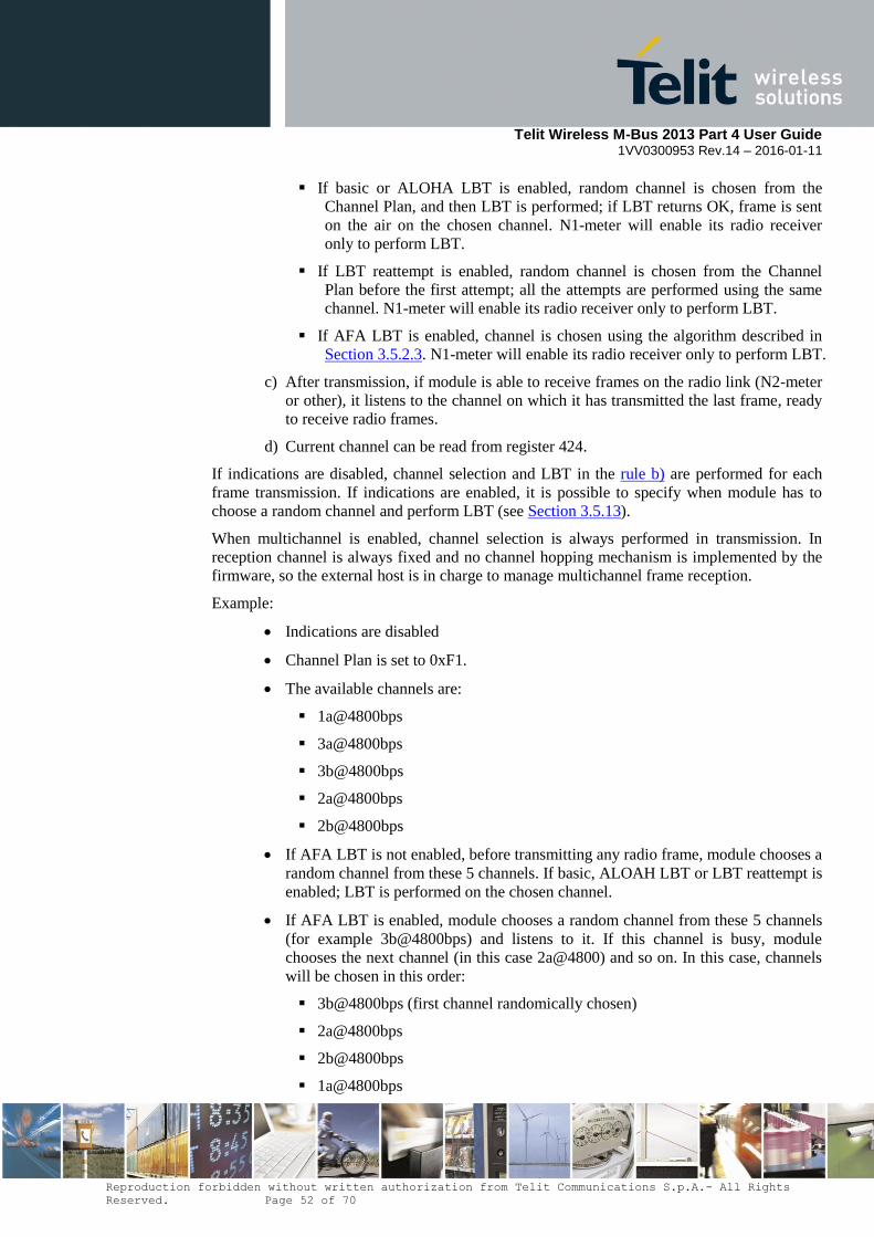
Telit Wireless M-Bus 2013 Part 4 User Guide
1VV0300953 Rev.14 – 2016-01-11
Reproduction forbidden without written authorization from Telit Communications S.p.A.- All Rights
Reserved. Page 52 of 70
If basic or ALOHA LBT is enabled, random channel is chosen from the
Channel Plan, and then LBT is performed; if LBT returns OK, frame is sent
on the air on the chosen channel. N1-meter will enable its radio receiver
only to perform LBT.
If LBT reattempt is enabled, random channel is chosen from the Channel
Plan before the first attempt; all the attempts are performed using the same
channel. N1-meter will enable its radio receiver only to perform LBT.
If AFA LBT is enabled, channel is chosen using the algorithm described in
Section 3.5.2.3. N1-meter will enable its radio receiver only to perform LBT.
c) After transmission, if module is able to receive frames on the radio link (N2-meter
or other), it listens to the channel on which it has transmitted the last frame, ready
to receive radio frames.
d) Current channel can be read from register 424.
If indications are disabled, channel selection and LBT in the rule b) are performed for each
frame transmission. If indications are enabled, it is possible to specify when module has to
choose a random channel and perform LBT (see Section 3.5.13).
When multichannel is enabled, channel selection is always performed in transmission. In
reception channel is always fixed and no channel hopping mechanism is implemented by the
firmware, so the external host is in charge to manage multichannel frame reception.
Example:
Indications are disabled
Channel Plan is set to 0xF1.
The available channels are:
1a@4800bps
3a@4800bps
3b@4800bps
2a@4800bps
2b@4800bps
If AFA LBT is not enabled, before transmitting any radio frame, module chooses a
random channel from these 5 channels. If basic, ALOAH LBT or LBT reattempt is
enabled; LBT is performed on the chosen channel.
If AFA LBT is enabled, module chooses a random channel from these 5 channels
(for example 3b@4800bps) and listens to it. If this channel is busy, module
chooses the next channel (in this case 2a@4800) and so on. In this case, channels
will be chosen in this order:
3b@4800bps (first channel randomically chosen)
2a@4800bps
2b@4800bps
1a@4800bps

Telit Wireless M-Bus 2013 Part 4 User Guide
1VV0300953 Rev.14 – 2016-01-11
Reproduction forbidden without written authorization from Telit Communications S.p.A.- All Rights
Reserved. Page 53 of 70
3a@4800bps
3.5.13. Indications (ME70-169)
When configuration register 490 is set to 0, indications are disabled and in operative mode
each frame arriving on the serial link is sent on the radio link, and each valid Wireless M-Bus
frame received on the radio link is sent on the serial link.
When configuration register 490 is set to 1, indications are enabled and in operative mode it is
possible to send/receive indications and frames together on the serial link. In this case serial
frame has an additional header to distinguish MBUS frames from indications.
MBUS frame
Header MBUS frame
1 byte this is the serial frame as
defined when indications
are disabled
Header is always 0x00 when serial frames are sent on the serial link by the RF
module (in the direction from the RF module to the user host).
Header in serial frames arriving on the serial link of the RF module (in the
direction from the user host to the RF module) can have the following values:
0x00 - Channel selection and assessment are not performed: frame will be
sent on the channel on which it has transmitted the last frame, without using
any LBT method (register 501 and bit 1 of register 453 are ignored).
0x01 - Channel selection and assessment are performed: before
transmitting any radio frame, depending on the configuration for
multichannel (register 423) and LBT (register 501 and bit 1 of register 453),
module selects a random channel and/or performs LBT. If the user host sends
a MBUS frame with Header equal to 0x01, an indication with Indication
Type 0x0000, 0x0001, 0x0002 or 0x0003 will be sent to the user host just
after the frame is sent to RF.
0x02 – Channel assessment is performed, new frame for a new LBT
reattempt: when bit 4 of register 501 is set to 1 (see Section 3.5.2.4), a new
frame can be sent between an LBT attempt and the next one. This frame can
be sent after the indication 0x0004. The first attempt is performed using the
header 0x01, the following ones using 0x02.
Indications
Header Length Reserved Indication Type Optional
1 byte 1 byte 1 byte 2 bytes From 0 to 16 bytes
Header is always 0xFF.
Length is the length indication: this field includes the length of Reserved,
Indication Type and Optional. For incoming indications (the indications sent by
Telit Wireless M-Bus 2013 Part 4 User Guide
1VV0300953 Rev.14 – 2016-01-11
Reproduction forbidden without written authorization from Telit Communications S.p.A.- All Rights
Reserved. Page 54 of 70
user), this field is present only if Length field is activated in Serial Rx Format
(bit 0 set to 1 in register 401). For outcoming indications (the indications sent to
user), this field is present only if Length field is activated in Serial Tx Format
(bit 0 set to 1 in register 402). When Length field is not activated, module uses
the time-out on the serial link (register 431).
Reserved is always 0xFF.
Indication Type can have the following values:
0x0000 - LBT OK: this outcoming indication is sent when channel
assessment is performed and LBT returns OK (channel free: frame can be
sent) or LBT is disabled. This indication is sent just after the frame is sent to
RF.
0x0001 - LBT override: this outcoming indication is sent when channel
assessment is performed, LBT returns FAIL but override option is enabled.
This indication is sent just after the frame is sent to RF.
0x0002 - LBT error: this outcoming indication is sent when channel
assessment is performed, LBT returns FAIL and override option is disabled.
This indication is sent just after LBT returns. If LBT reattempt is enabled,
this indication is sent if the last attempt returns FAIL and override is
disabled.
0x0003 – LBT reattempt: error in the current attempt: this outcoming
indication is sent when channel assessment is performed with LBT reattempt,
and the current attempt returns FAIL. This indication is sent just after LBT
returns.
0x0004 - LBT reattempt: new attempt can be performed; waiting for a
new frame: this outcoming indication is sent when bit 4 of register 501 is set
to 1. Module waits for a new frame for the next attempt.
0x0005 - LBT reattempt: error; algorithm has been stopped: this
outcoming indication is sent when module exits from LBT reattempt.
Examples:
bit 4 of register 501 is set to 0: a new serial frame is sent during the
algorithm;
bit 4 of register 501 is set to 1: a new serial frame is sent before the
indication 0x0004 has been received.
0x0006 – synchronized frame: this outcoming indication is sent when bit 4
of register 453 is set to 1. Module has waited for tROmin to send
automatically the frame.
0x0007 – not synchronized frame: this outcoming indication is sent when
bit 4 of register 453 is set to 1. Module has received a serial frame after
tROmax, so this frame is immediately sent on the air.
0x0010 - Standby: this outcoming indication is sent just before the module
goes in standby mode. This indication is not sent during the LBT reattempt
algorithm and during FAC.
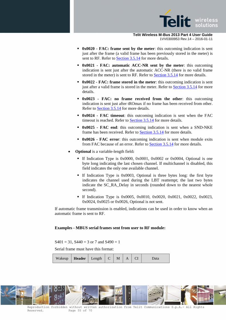
Telit Wireless M-Bus 2013 Part 4 User Guide
1VV0300953 Rev.14 – 2016-01-11
Reproduction forbidden without written authorization from Telit Communications S.p.A.- All Rights
Reserved. Page 55 of 70
0x0020 - FAC: frame sent by the meter: this outcoming indication is sent
just after the frame (a valid frame has been previously stored in the meter) is
sent to RF. Refer to Section 3.5.14 for more details.
0x0021 - FAC: automatic ACC-NR sent by the meter: this outcoming
indication is sent just after the automatic ACC-NR (there is no valid frame
stored in the meter) is sent to RF. Refer to Section 3.5.14 for more details.
0x0022 - FAC: frame stored in the meter: this outcoming indication is sent
just after a valid frame is stored in the meter. Refer to Section 3.5.14 for more
details.
0x0023 - FAC: no frame received from the other: this outcoming
indication is sent just after tROmax if no frame has been received from other.
Refer to Section 3.5.14 for more details.
0x0024 - FAC timeout: this outcoming indication is sent when the FAC
timeout is reached. Refer to Section 3.5.14 for more details.
0x0025 - FAC end: this outcoming indication is sent when a SND-NKE
frame has been received. Refer to Section 3.5.14 for more details.
0x0026 - FAC error: this outcoming indication is sent when module exits
from FAC because of an error. Refer to Section 3.5.14 for more details.
Optional is a variable-length field:
If Indication Type is 0x0000, 0x0001, 0x0002 or 0x0004, Optional is one
byte long indicating the last chosen channel. If multichannel is disabled, this
field indicates the only one available channel.
If Indication Type is 0x0003, Optional is three bytes long: the first byte
indicates the channel used during the LBT reattempt; the last two bytes
indicate the SC_RA_Delay in seconds (rounded down to the nearest whole
second).
If Indication Type is 0x0005, 0x0010, 0x0020, 0x0021, 0x0022, 0x0023,
0x0024, 0x0025 or 0x0026, Optional is not sent.
If automatic frame transmission is enabled, indications can be used in order to know when an
automatic frame is sent to RF.
Examples - MBUS serial frames sent from user to RF module:
S401 = 31, S440 = 3 or 7 and S490 = 1
Serial frame must have this format:
Wakeup Header Length C M A CI Data
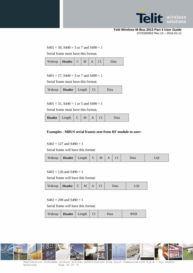
Telit Wireless M-Bus 2013 Part 4 User Guide
1VV0300953 Rev.14 – 2016-01-11
Reproduction forbidden without written authorization from Telit Communications S.p.A.- All Rights
Reserved. Page 56 of 70
S401 = 30, S440 = 3 or 7 and S490 = 1
Serial frame must have this format:
Wakeup Header C M A CI Data
S401 = 17, S440 = 3 or 7 and S490 = 1
Serial frame must have this format:
Wakeup Header Length CI Data
S401 = 31, S440 = 1 or 5 and S490 = 1
Serial frame must have this format:
Header Length C M A CI Data
Examples - MBUS serial frames sent from RF module to user:
S402 = 127 and S490 = 1
Serial frame will have this format:
Wakeup Header Length C M A CI Data LQI
S402 = 126 and S490 = 1
Serial frame will have this format:
Wakeup Header C M A CI Data LQI
S402 = 209 and S490 = 1
Serial frame will have this format:
Wakeup Header Length CI Data RSSI
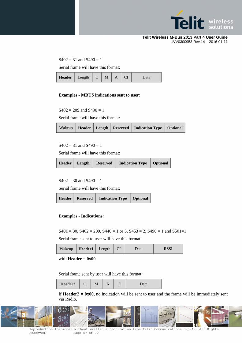
Telit Wireless M-Bus 2013 Part 4 User Guide
1VV0300953 Rev.14 – 2016-01-11
Reproduction forbidden without written authorization from Telit Communications S.p.A.- All Rights
Reserved. Page 57 of 70
S402 = 31 and S490 = 1
Serial frame will have this format:
Header Length C M A CI Data
Examples - MBUS indications sent to user:
S402 = 209 and S490 = 1
Serial frame will have this format:
Wakeup Header Length Reserved Indication Type Optional
S402 = 31 and S490 = 1
Serial frame will have this format:
Header Length Reserved Indication Type Optional
S402 = 30 and S490 = 1
Serial frame will have this format:
Header Reserved Indication Type Optional
Examples - Indications:
S401 = 30, S402 = 209, S440 = 1 or 5, S453 = 2, S490 = 1 and S501=1
Serial frame sent to user will have this format:
Wakeup Header1 Length CI Data RSSI
with Header = 0x00
Serial frame sent by user will have this format:
Header2 C M A CI Data
If Header2 = 0x00, no indication will be sent to user and the frame will be immediately sent
via Radio.

Telit Wireless M-Bus 2013 Part 4 User Guide
1VV0300953 Rev.14 – 2016-01-11
Reproduction forbidden without written authorization from Telit Communications S.p.A.- All Rights
Reserved. Page 58 of 70
If Header2 = 0x01, this indication will be sent to user just after the MBUS frame is sent to
RF:
Header3 Reserved Indication Type Optional
With Header3 = 0xFF, Reserved = 0xFF, Indication Type = 0x0000 or 0x0001(in this case
it depends on ALOHA LBT result). Optional indicates the channel on which LBT has been
performed.
S401 = 30, S402 = 209, S440 = 1 or 5, S453 = 2, S490 = 1 and S501=25
First LBT attempt: serial frame sent by user will have this format with Header = 0x01:
Header C M A CI Data
This indication will be sent to user just after the MBUS frame is sent to RF:
Header2 Reserved Indication Type Optional
With Header2 = 0xFF, Reserved = 0xFF
Indication Type can be:
0x0000 if LBT returns OK. Optional indicates the channel on which LBT has
been performed.
0x0003 if LBT returns FAIL. A new attempt will be performed. Optional
indicates the channel on which LBT has been performed and the SC_RA_Delay.
o In this case, after SC_RA_Delay, this indication will be sent to user:
Header3 Reserved Indication Type2 Optional2
With Header3 = 0xFF, Reserved = 0xFF and Indication Type2 = 0x0004.
Optional2 indicated the radio channel.
Now new frame can be sent: serial frame sent by user will have this format
with Header4 = 0x02:
Header4 C M A CI Data
LBT reattempt algorithm will go on until LBT returns OK or maximum
number of LBT attempt is reached.
3.5.14. Frequent Access Cycle (ME70-169)
Bit 0 of configuration register 530 allows enabling support for the Frequent Access Cycle on
meter side. Indications are required for this functionality.
If the meter transmits a frame containing an Extended Link Layer, if the D-field is set to 1,
module will use the fast response delay (registers 531 and 533); else if the D-field is set to 0,
the slow response delay (registers 535 and 537) will be used.

Telit Wireless M-Bus 2013 Part 4 User Guide
1VV0300953 Rev.14 – 2016-01-11
Reproduction forbidden without written authorization from Telit Communications S.p.A.- All Rights
Reserved. Page 59 of 70
If the meter transmits a frame not containing an Extended Link Layer, if the bit 1 of register
530 is set to 1, module will use the fast response delay (registers 531 and 533); otherwise the
slow response delay (registers 535 and 537) will be used.
The response delay tRO is calculated from end of the last bit transmitted by meter to expected
start of the preamble of the frame received from other. Meter can receive frames between
tROmin and tROmax after each its transmission.
The reference time point for the transmission delay txD and for the FAC timeout is the end of
preamble (end of sync sequence) of the meter transmission. Meter can send frames every txD
seconds.
When Frequent Access Cycle is enabled, these rules apply:
1) The first frame in a FAC session is always sent by meter performing the channel
assessment. When a frame with Header = 0x01 is received from serial port, meter
performs the channel assessment to send the first unsolicited frame to other.
Indication with the channel assessment result is sent to host. If the frame cannot be
sent, FAC will be not started.
2) If the first unsolicited frame is sent, meter waits for tROmin.
3) After the first unsolicited frame, between tROmin and tROmax, meter listens to the
radio for an incoming frame from other. Only one frame can be received in this
window. If no frame is received from other, meter exits from FAC.
4) If other sends a command frame after the meter unsolicited frame, FAC will be
started. The frame received from other will be sent to user with Header = 0x00.
5) Host can send serial frames (with Header = 0x00) to meter after tROmax and before
txD. These frames will be stored if they have the same access number of the last
frame received from other. When a frame is stored, an indication with IndicationType
= 0x0022 will be sent to user.
6) When txD is reached, if there is a valid frame stored in the meter, it will be sent to
other and an indication with IndicationType = 0x0020 will be sent to user; otherwise
if there is no stored frame, an automatic ACC-NR frame is sent to other and an
indication with IndicationType = 0x0021 will be sent to user.
7) Between tROmin and tROmax, meter listens to the radio for an incoming frame from
other. Only one frame can be received in this window. If no frame is received from
other, an indication with IndicationType = 0x0023 will be sent to user at tROmax and
meter will repeat the last frame when txD will be reached.
8) FAC terminates if meter receives a SND-NKE frame. In this case an indication with
IndicationType = 0x0025 will be sent to user.
9) FAC lasts until the FAC timeout after the last successful reception of a command or a
request from other. If timeout is reached, an indication with IndicationType = 0x0024
will be sent to user.
10) If host sends serial frames before tROmax, FAC exits and an indication with
IndicationType = 0x0026 will be sent to user.

Telit Wireless M-Bus 2013 Part 4 User Guide
1VV0300953 Rev.14 – 2016-01-11
Reproduction forbidden without written authorization from Telit Communications S.p.A.- All Rights
Reserved. Page 60 of 70
3.5.14.1. FAC example 1: Other without automatic frames
Meter configuration – list of the registers with values different from default:
400=16; 401=18; 402=30; 420=4; 453=2; 490=1; 501=1; 530=1
Other configuration – list of the registers with values different from default:
400=17; 401=18; 402=30; 416=19; 418=8; 420=4; 453=16
Meter with ALOHA LBT, FAC and indications.
Other with synchronized frames.
In this example data fields after the transport layer are meaningless.
1. Host on the meter-side sends:
0x01 0x44 0x7d 0x91 0x00 0x00 0x80 0x31 0x32 0x33 0x34 0x35
Channel assessment con ALOHA LBT (header = 0x01), C-field = 0x44 (SND-NR),
CI-field = 0x7d (short transport layer), ACC = 0x91, STS = 0x00,
CW = 0x00 0x80 (bidirectional without encryption),
DataField = 0x31 0x32 0x33 0x34 0x35
2. As soon as the meter sends successfully the frame, host on the meter-side receives the
indication:
0xff 0xff 0x00 0x00 0x04
Frame successfully sent on the channel 4
3. Host on the other-side receives the frame:
0x44 0xae 0x0c 0x78 0x56 0x34 0x12 0x01 0x07 0x7d 0x91 0x00 0x00 0x80 0x31 0x32
0x33 0x34 0x35 C-field = 0x44, Address = 0xae 0x0c 0x78 0x56 0x34 0x12 0x01 0x07, CI-field = 0x7d,
ACC = 0x91, STS = 0x00, CW = 0x00, DataField = 0x31 0x32 0x33 0x34 0x35
4. Host on the other-side wants to start a FAC; it sends before tROmin (in this case 1100
msec) the frame:
0x43 0x60 0x78 0x56 0x34 0x12 0xae 0x0c 0x01 0x07 0x01 0x00 0x00 0x80 0x35 0x36
0x37 0x38 0x39
C-field = 0x43 (SND-UD2), CI-field = 0x60 (long transport layer),
MeterAddress = 0x78 0x56 0x34 0x12, Meter M-Field = 0xae 0x0c,
MeterVersion = 0x01, MeterDeviceType = 0x07, ACC = 0x01, STS = 0x00,
CW = 0x00 0x80 (bidirectional without encryption),
DataField = 0x35 0x36 0x37 0x38 0x39
5. This frame is automatically sent from other at time tROmin.
6. Host on the meter-side receives:
0x00 0x43 0xae 0x0c 0x78 0x56 0x34 0x13 0x01 0x08 0x60 0x78 0x56 0x34 0x12 0xae
0x0c 0x01 0x07 0x01 0x00 0x00 0x80 0x35 0x36 0x37 0x38 0x39 Received frame (header = 0x00),
Address = 0xae 0x0c 0x78 0x56 0x34 0x13 0x01 0x08, CI-field = 0x60,
MeterAddress = 0x78 0x56 0x34 0x12, Meter M-Field = 0xae 0x0c,

Telit Wireless M-Bus 2013 Part 4 User Guide
1VV0300953 Rev.14 – 2016-01-11
Reproduction forbidden without written authorization from Telit Communications S.p.A.- All Rights
Reserved. Page 61 of 70
MeterVersion = 0x01, MeterDeviceType = 0x07, ACC = 0x01, STS = 0x00,
CW = 0x00 0x80, DataField = 0x35 0x36 0x37 0x38 0x39
7. FAC starts, but host on the meter-side does not have any ready frame.
8. Host on the meter-side receives periodically these two indications:
0xff 0xff 0x21 0x00 (automatic ACC-NR at txD)
0xff 0xff 0x23 0x00 (no frame received from other after tROmax)
9. Other periodically receives ACC-NR at txD:
0x47 0xae 0x0c 0x78 0x56 0x34 0x12 0x01 0x07 0x8a 0x01 0x00 0x00 0x80
C-field = 0x47 (ACC-NR), Address = 0xae 0x0c 0x78 0x56 0x34 0x12 0x01 0x07,
CI-field = 0x8a (short transport without data),
ACC = 0x01 (ACC of the last request from other), STS = 0x00,
CW = 0x00 0x80 (bidirectional without encryption)
10. When the response is ready, host on the meter-side sends between tROmax and txD the
frame:
0x00 0x08 0x7d 0x01 0x00 0x00 0x80 0x41 0x42 0x43 0x44 0x45
No channel assessment (header = 0x00), C-field = 0x08 (RSP-UD),
CI-field = 0x7d (short transport layer),
ACC = 0x01 (ACC of the last request from other), STS = 0x00,
CW = 0x00 0x80 (bidirectional without encryption),
DataField = 0x41 0x42 0x43 0x44 0x45
11. This frame is stored with this indication:
0xff 0xff 0x22 0x00
12. At time txD the meter automatically sends the response frame to RF and this indication
to its host:
0xff 0xff 0x20 0x00
13. Other receives the response frame:
0x08 0xae 0x0c 0x78 0x56 0x34 0x12 0x01 0x07 0x7d 0x01 0x00 0x00 0x80 0x41 0x42
0x43 0x44 0x45 C-field = 0x08, Address = 0xae 0x0c 0x78 0x56 0x34 0x12 0x01 0x07, CI-field = 0x7d,
ACC = 0x01, STS = 0x00, CW = 0x00 0x80
14. If other does not reply, meter will continue to send the last RSP-UD frame to RF at time
txD and these indicatons to its host:
0xff 0xff 0x20 0x00 (send last RSP-UD at txD)
0xff 0xff 0x23 0x00 (no frame received from other after tROmax)
15. Other wants to end FAC; its host sends before tROmin:
0x40 0x80 0x78 0x56 0x34 0x12 0xae 0x0c 0x01 0x07 0x02 0x00 0x00 0x80 C-field = 0x40 (SND-NKE), CI-field = 0x80 (long transport layer with no data),
MeterAddress = 0x78 0x56 0x34 0x12, Meter M-Field = 0xae 0x0c,
MeterVersion = 0x01, MeterDeviceType = 0x07, ACC = 0x02, STS = 0x00,
CW = 0x00 0x80 (bidirectional without encryption)

Telit Wireless M-Bus 2013 Part 4 User Guide
1VV0300953 Rev.14 – 2016-01-11
Reproduction forbidden without written authorization from Telit Communications S.p.A.- All Rights
Reserved. Page 62 of 70
16. Host on the meter-side receives:
0x00 0x40 0xae 0x0c 0x78 0x56 0x34 0x13 0x01 0x08 0x80 0x78 0x56 0x34 0x12 0xae
0x0c 0x01 0x07 0x02 0x00 0x00 0x80
and this indication:
0xff 0xff 0x25 0x00 (FAC end)
3.5.14.2. FAC example 2: Other with automatic frames
Meter configuration – list of the registers with values different from default:
400=16; 401=18; 402=30; 420=4; 453=2; 490=1; 501=1; 530=1
Other configuration – list of the registers with values different from default:
400=17; 401=18; 402=30; 416=19; 418=8: 420=4; 453=248; 490=1
Meter with ALOHA LBT, FAC and indications.
Other with indications and multiframe, automatic and synchronized frames.
In this example data fields after the transport layer are meaningless.
Before the beginning of each FAC, other stores two frames without sending them to radio:
SND-UD2 and SND-NKE.
1. Host on the other-side sends:
0x60 0x43 0x60 0xff 0xff 0xff 0xff 0xff 0xff 0xff 0xff 0x01 0x00 0x00 0x80 0x35 0x36
0x37 0x38 0x39
Store new frame at slot 0 = 0x60,
C-field = 0x43 (SND-UD2), CI-field = 0x60 (long transport layer),
0xFF address = 0xff 0xff 0xff 0xff 0xff 0xff 0xff 0xff,
ACC = 0x01, STS = 0x00,
CW = 0x00 0x80 (bidirectional without encryption),
DataField = 0x35 0x36 0x37 0x38 0x39
2. Host on the other-side receives this ACK:
0x01 0x60 (stored frame at slot 0)
3. Host on the other-side sends:
0x61 0x40 0x80 0xff 0xff 0xff 0xff 0xff 0xff 0xff 0xff 0x02 0x00 0x00 0x80 Store new frame at slot 1 = 0x61,
C-field = 0x40 (SND-NKE), CI-field = 0x80 (long transport layer with no data),
0xFF address = 0xff 0xff 0xff 0xff 0xff 0xff 0xff 0xff,
ACC = 0x02, STS = 0x00,
CW = 0x00 0x80 (bidirectional without encryption)
4. Host on the other-side receives this ACK:
0x01 0x61 (stored frame at slot 1)
5. Host on the meter-side sends:
0x01 0x44 0x7d 0x91 0x00 0x00 0x80 0x31 0x32 0x33 0x34 0x35
Channel assessment con ALOHA LBT (header = 0x01), C-field = 0x44 (SND-NR),
CI-field = 0x7d (short transport layer), ACC = 0x91, STS = 0x00,
Telit Wireless M-Bus 2013 Part 4 User Guide
1VV0300953 Rev.14 – 2016-01-11
Reproduction forbidden without written authorization from Telit Communications S.p.A.- All Rights
Reserved. Page 63 of 70
CW = 0x00 0x80 (bidirectional without encryption),
DataField = 0x31 0x32 0x33 0x34 0x35
6. As soon as the meter sends successfully the frame, host on the meter-side receives the
indication:
0xff 0xff 0x00 0x00 0x04
Frame successfully sent on the channel 4
7. Host on the other-side receives the frame:
0x00 0x44 0xae 0x0c 0x78 0x56 0x34 0x12 0x01 0x07 0x7d 0x91 0x00 0x00 0x80 0x31
0x32 0x33 0x34 0x35 Received frame (multiframe) = 0x00,
C-field = 0x44, Address = 0xae 0x0c 0x78 0x56 0x34 0x12 0x01 0x07, CI-field = 0x7d,
ACC = 0x91, STS = 0x00, CW = 0x00, DataField = 0x31 0x32 0x33 0x34 0x35
8. Other automatically sends the first stored frame at time tROmin, replacing the 0xFF
address with the meter one; it sends to its host this indication:
0xff 0xff 0x06 0x00
Synchronized frame successfully sent
9. Host on the meter-side receives:
0x00 0x43 0xae 0x0c 0x78 0x56 0x34 0x13 0x01 0x08 0x60 0x78 0x56 0x34 0x12 0xae
0x0c 0x01 0x07 0x01 0x00 0x00 0x80 0x35 0x36 0x37 0x38 0x39 Received frame (header = 0x00),
Address = 0xae 0x0c 0x78 0x56 0x34 0x13 0x01 0x08, CI-field = 0x60,
MeterAddress = 0x78 0x56 0x34 0x12, Meter M-Field = 0xae 0x0c,
MeterVersion = 0x01, MeterDeviceType = 0x07, ACC = 0x01, STS = 0x00,
CW = 0x00 0x80, DataField = 0x35 0x36 0x37 0x38 0x39
10. FAC starts, but host on the meter-side does not have any ready frame.
11. Host on the meter-side receives periodically this indication at txD:
0xff 0xff 0x21 0x00 (automatic ACC-NR)
12. Host on the meter-side receives periodically this frame at tROmin:
0x00 0x43 0xae 0x0c 0x78 0x56 0x34 0x13 0x01 0x08 0x60 0x78 0x56 0x34 0x12 0xae
0x0c 0x01 0x07 0x01 0x00 0x00 0x80 0x35 0x36 0x37 0x38 0x39
13. Other periodically receives ACC-NR at txD:
0x00 0x47 0xae 0x0c 0x78 0x56 0x34 0x12 0x01 0x07 0x8a 0x01 0x00 0x00 0x80
Received frame (multiframe) = 0x00,
C-field = 0x47 (ACC-NR), Address = 0xae 0x0c 0x78 0x56 0x34 0x12 0x01 0x07,
CI-field = 0x8a (short transport without data),
ACC = 0x01 (ACC of the last request from other), STS = 0x00,
CW = 0x00 0x80 (bidirectional without encryption)
14. Other automatically repeats the first stored frame at tROmin, replacing the 0xFF address
with the meter one, until it receives a frame from meter with PRM=0 and same ACC.
Every transmission is signaled with this indication:
Telit Wireless M-Bus 2013 Part 4 User Guide
1VV0300953 Rev.14 – 2016-01-11
Reproduction forbidden without written authorization from Telit Communications S.p.A.- All Rights
Reserved. Page 64 of 70
0xff 0xff 0x06 0x00
Synchronized frame successfully sent
15. When the response is ready, host on the meter-side sends between tROmax and txD the
frame:
0x00 0x08 0x7d 0x01 0x00 0x00 0x80 0x41 0x42 0x43 0x44 0x45
No channel assessment (header = 0x00), C-field = 0x08 (RSP-UD),
CI-field = 0x7d (short transport layer),
ACC = 0x01 (ACC of the last request from other), STS = 0x00,
CW = 0x00 0x80 (bidirectional without encryption),
DataField = 0x41 0x42 0x43 0x44 0x45
16. This frame is stored with this indication:
0xff 0xff 0x22 0x00
17. At time txD the meter automatically sends the response frame to RF and this indication
to its host:
0xff 0xff 0x20 0x00
18. Other receives the response frame:
0x00 0x08 0xae 0x0c 0x78 0x56 0x34 0x12 0x01 0x07 0x7d 0x01 0x00 0x00 0x80 0x41
0x42 0x43 0x44 0x45
Received frame (multiframe) = 0x00,
C-field = 0x08, Address = 0xae 0x0c 0x78 0x56 0x34 0x12 0x01 0x07, CI-field = 0x7d,
ACC = 0x01, STS = 0x00, CW = 0x00 0x80
19. Other automatically replies; it deletes the first stored frame (other received a frame with
PRM=0 and same ACC) and sends the second stored frame at time tROmin, replacing
the 0xFF address with the meter one; it sends to its host this indication:
0xff 0xff 0x06 0x00
Synchronized frame successfully sent
20. Host on the meter-side receives:
0x00 0x40 0xae 0x0c 0x78 0x56 0x34 0x13 0x01 0x08 0x80 0x78 0x56 0x34 0x12 0xae
0x0c 0x01 0x07 0x02 0x00 0x00 0x80
and this indication:
0xff 0xff 0x25 0x00 (FAC end)
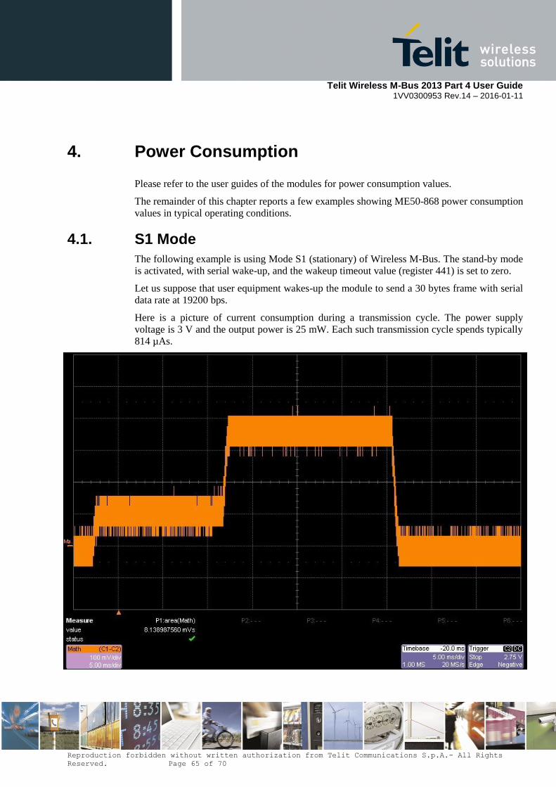
Telit Wireless M-Bus 2013 Part 4 User Guide
1VV0300953 Rev.14 – 2016-01-11
Reproduction forbidden without written authorization from Telit Communications S.p.A.- All Rights
Reserved. Page 65 of 70
4. Power Consumption
Please refer to the user guides of the modules for power consumption values.
The remainder of this chapter reports a few examples showing ME50-868 power consumption
values in typical operating conditions.
4.1. S1 Mode
The following example is using Mode S1 (stationary) of Wireless M-Bus. The stand-by mode
is activated, with serial wake-up, and the wakeup timeout value (register 441) is set to zero.
Let us suppose that user equipment wakes-up the module to send a 30 bytes frame with serial
data rate at 19200 bps.
Here is a picture of current consumption during a transmission cycle. The power supply
voltage is 3 V and the output power is 25 mW. Each such transmission cycle spends typically
814 µAs.

Telit Wireless M-Bus 2013 Part 4 User Guide
1VV0300953 Rev.14 – 2016-01-11
Reproduction forbidden without written authorization from Telit Communications S.p.A.- All Rights
Reserved. Page 66 of 70
Here is a table of average consumption versus the period of transmission cycles.
Sleep Time Equivalent Consumption (µA)
1 second 815.4
10 seconds 82.8
1 minute 15
1 hour 1.6
1 day 1.4
4.2. R2 Mode
The following example is using the R2 mode (frequent receive) of Wireless M-Bus. The
stand-by mode is activated, with cyclic wake-up.
With this functioning mode, the meter module wakes up periodically to listen to the radio
channel during a very short time. If some activity is detected, the module stays awake to
receive the frame, else returns quickly in stand-by mode.
Assuming that the concentrator is rarely present and considering that this band is clear (duty
cycle < 1% as requested by ETSI rules in EN 300 220-2), the main current consumption is
due to wake up cycles without detection of energy.
Here is a picture of a typical current consumption pattern during a wake-up cycle. The power
supply voltage is 3 V. In this case, Wakeup Time Out register 441 has no influence since no
event is detected.
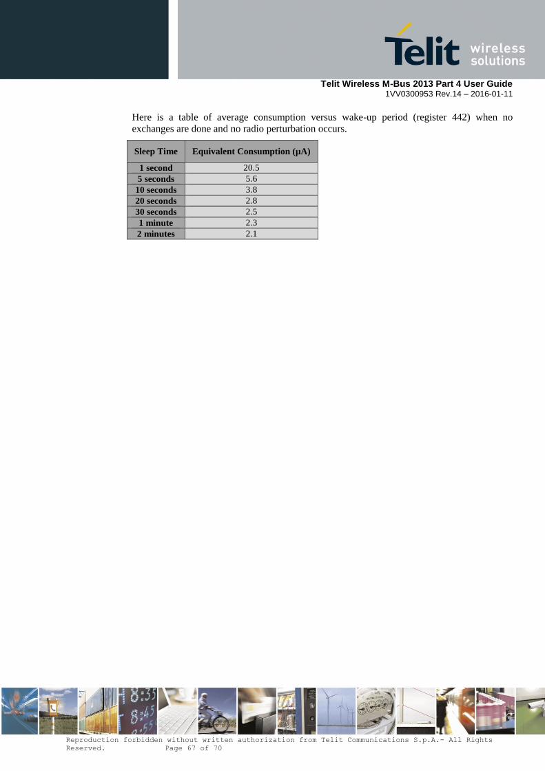
Telit Wireless M-Bus 2013 Part 4 User Guide
1VV0300953 Rev.14 – 2016-01-11
Reproduction forbidden without written authorization from Telit Communications S.p.A.- All Rights
Reserved. Page 67 of 70
Here is a table of average consumption versus wake-up period (register 442) when no
exchanges are done and no radio perturbation occurs.
Sleep Time Equivalent Consumption (µA)
1 second 20.5
5 seconds 5.6
10 seconds 3.8
20 seconds 2.8
30 seconds 2.5
1 minute 2.3
2 minutes 2.1

Telit Wireless M-Bus 2013 Part 4 User Guide
1VV0300953 Rev.14 – 2016-01-11
Reproduction forbidden without written authorization from Telit Communications S.p.A.- All Rights
Reserved. Page 68 of 70
5. Acronyms and Abbreviations
ACP Adjacent Channel Power
AES Advanced Encryption Standard
AFA Adaptive Frequency Agility
ALA Application Layer Address
BCD Binary Coded Decimal
BER Bit Error Rate
CBC Cipher Block Chaining
CER Character Error Rate
dBm Power level in decibel milliwatt (10 log (P/1mW))
DES Data Encryption Standard
EMC Electro Magnetic Compatibility
EEPROM Electrically Erasable Programmable Read-Only Memory
ETR ETSI Technical Report
ETSI European Telecommunications Standards Institute
FAC Frequent Access Cycle
FSK Frequency Shift Keying
GFSK Gaussian Frequency Shift Keying
IF Intermediate Frequency
ISM Industrial, Scientific and Medical
kbps kilobits per second
kcps kilochips per second
LBT Listen Before Talk
LLA Link Layer Address
LNA Low Noise Amplifier
LQI Link Quality Indication
M-Bus Meter Bus
MHz Mega Hertz
OMS Open Metering System
PLL Phase Lock Loop
NRZ Non Return to Zero
RF Radio Frequency
RoHS Restriction of Hazardous Substances
RSSI Received Signal Strength Indicator
Rx Reception
SRD Short Range Device
Tx Transmission
SMD Surface Mounted Device
VCO Voltage Controlled Oscillator
VCTCXO Voltage Controlled and Temperature Compensated Crystal Oscillator
VHF Very High Frequency
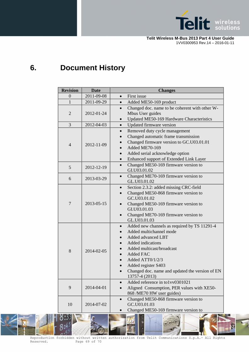
Telit Wireless M-Bus 2013 Part 4 User Guide
1VV0300953 Rev.14 – 2016-01-11
Reproduction forbidden without written authorization from Telit Communications S.p.A.- All Rights
Reserved. Page 69 of 70
6. Document History
Revision Date Changes
0 2011-09-08 First issue
1 2011-09-29 Added ME50-169 product
2 2012-01-24
Changed doc. name to be coherent with other W-
Mbus User guides
Updated ME50-169 Hardware Characteristics
3 2012-04-03 Updated firmware version
4 2012-11-09
Removed duty cycle management
Changed automatic frame transmission
Changed firmware version to GC.U03.01.01
Added ME70-169
Added serial acknowledge option
Enhanced support of Extended Link Layer
5 2012-12-19 Changed ME50-169 firmware version to
GI.U03.01.02
6 2013-03-29 Changed ME70-169 firmware version to
GL.U03.01.02
7 2013-05-15
Section 2.3.2: added missing CRC-field
Changed ME50-868 firmware version to
GC.U03.01.02
Changed ME50-169 firmware version to
GI.U03.01.03
Changed ME70-169 firmware version to
GL.U03.01.03
8 2014-02-05
Added new channels as required by TS 11291-4
Added multichannel mode
Added advanced LBT
Added indications
Added multicast/broadcast
Added FAC
Added ATT0/1/2/3
Added register S403
Changed doc. name and updated the version of EN
13757-4 (2013)
9 2014-04-01
Added reference in to1vv0301021
Aligned Consumption, PER values with XE50-
868 /ME70 HW user guides)
10 2014-07-02
Changed ME50-868 firmware version to
GC.U03.01.03
Changed ME50-169 firmware version to
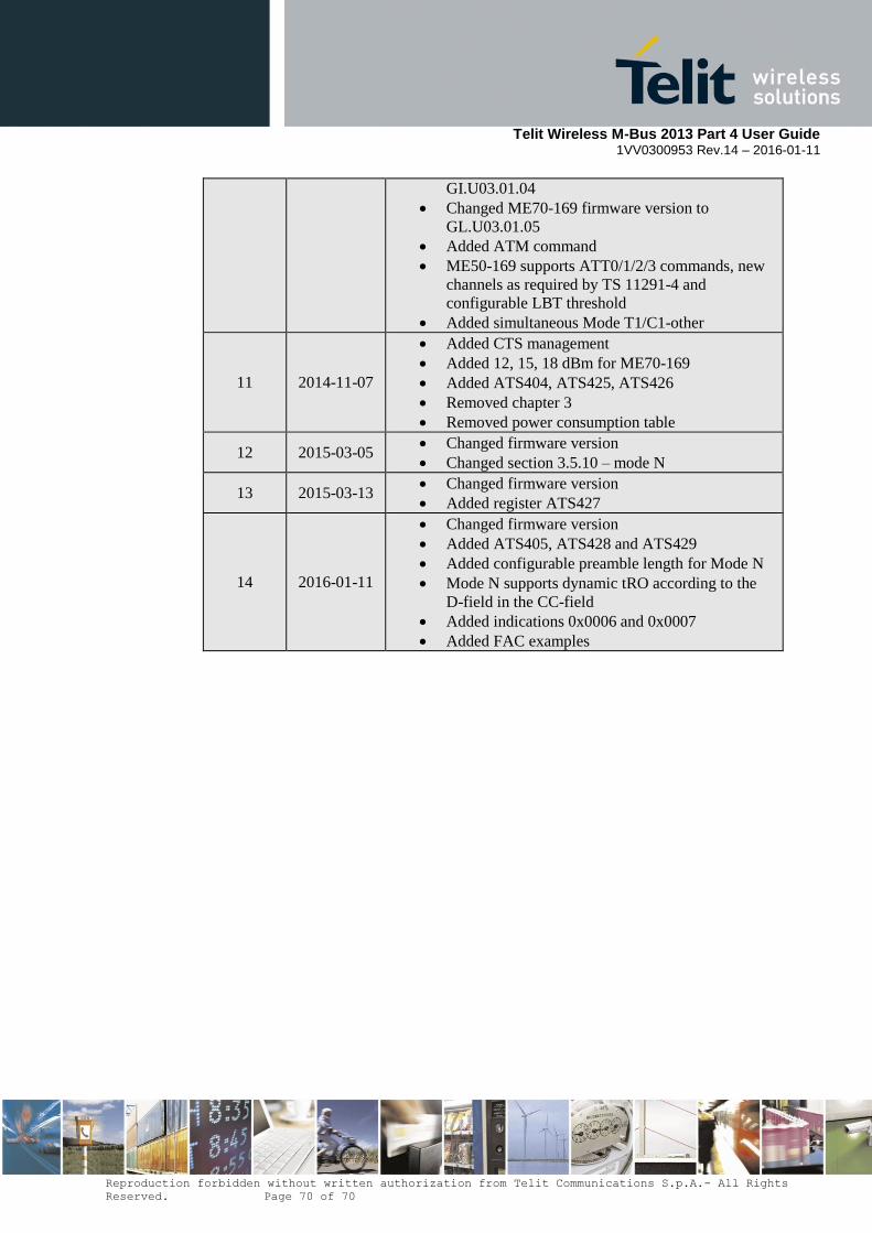
Telit Wireless M-Bus 2013 Part 4 User Guide
1VV0300953 Rev.14 – 2016-01-11
Reproduction forbidden without written authorization from Telit Communications S.p.A.- All Rights
Reserved. Page 70 of 70
GI.U03.01.04
Changed ME70-169 firmware version to
GL.U03.01.05
Added ATM command
ME50-169 supports ATT0/1/2/3 commands, new
channels as required by TS 11291-4 and
configurable LBT threshold
Added simultaneous Mode T1/C1-other
11 2014-11-07
Added CTS management
Added 12, 15, 18 dBm for ME70-169
Added ATS404, ATS425, ATS426
Removed chapter 3
Removed power consumption table
12 2015-03-05 Changed firmware version
Changed section 3.5.10 – mode N
13 2015-03-13 Changed firmware version
Added register ATS427
14 2016-01-11
Changed firmware version
Added ATS405, ATS428 and ATS429
Added configurable preamble length for Mode N
Mode N supports dynamic tRO according to the
D-field in the CC-field
Added indications 0x0006 and 0x0007
Added FAC examples