Embed Size (px)
Citation preview

TelecomunicazioniDocente: Andrea Baiocchi
DIET - Stanza 107, 1° piano palazzina “P. Piga”
Via Eudossiana 18
E-mail: [email protected]
University of Roma“Sapienza”
Corso di Laurea in Ingegneria Gestionale
A.A. 2014/2015
Telecomunicazioni - a.a. 2014/2015 - Prof. Andrea Baiocchi
About bit and numbers…
There are 10 types of people.Those who understand binary numbers and thosethat do not.
[anonymous joke]
But let your communication be Yea, yea; Nay, nay.For whatsoever is more than these, cometh of evil.
[Matthew, 5:37]

Telecomunicazioni - a.a. 2014/2015 - Prof. Andrea Baiocchi
Programma
1. SERVIZI E RETI DI TELECOMUNICAZIONE
2. ARCHITETTURE DI COMUNICAZIONE EMODI DI TRASFERIMENTO
3. FONDAMENTI DI COMUNICAZIONI
4. ACCESSO MULTIPLO
5. LO STRATO DI COLLEGAMENTO
6. LO STRATO DI RETE IN INTERNET
7. LO STRATO DI TRASPORTO IN INTERNET
Telecomunicazioni - a.a. 2014/2015 - Prof. Andrea Baiocchi
Fundamentals of communicationsA roadmap! Digital Representation of Information! Digital Representation of Analog Signals! Why Digital Communications?! Characterization of Communication Channels! Fundamental Limits in Digital Transmission! Line Coding! Modems and Digital Modulation! Properties of Media and Digital Transmission Systems! Error Detection and Correction
Chapter 3

Fundamentals ofcommunications
Digital Representation ofInformation
Adapted from slides of the book:A. Leon Garcia, I. Widjaja, “Communication
networks”, McGraw Hill, 2004
Telecomunicazioni - a.a. 2014/2015 - Prof. Andrea Baiocchi
Bits, numbers, information
! Bit: BInary digiT! Either symbol belonging to a set of two elements or
number with value 0 or 1! n bits: digital representation for 0, 1, … , 2n–1! Byte or Octet, n = 8! Computer word, typically n = 32, or 64
! n bits allows enumeration of 2n possibilities! n-bit field in a header! n-bit representation of a voice sample! Message consisting of n bits
! The number of bits required to represent a messageis a measure of its information content! More bits -> More information

Telecomunicazioni - a.a. 2014/2015 - Prof. Andrea Baiocchi
Block vs. Stream Information
Block
! Information that occurs in a single, delimited data unit(bit string)! Text message, Data file, JPEG image, MPEG file
! Size = bits / block
Stream
! Information that is produced and possibly conveyedover a communication system continuously! Real-time voice (e.g. telephony)
! Streaming video
! Bit rate = bits / second
Telecomunicazioni - a.a. 2014/2015 - Prof. Andrea Baiocchi
Information and …
! Information is a logical concept! Made precise by Shannon theory: more later on
! Information can appear under two basic forms! A SEQUENCE of values taken from a discrete and
finite set (DIGITAL INFORMATION)
! A REAL-VALUED FUNCTION of one or more REAL-VALUED variables (ANALOG INFORMATION)
! Examples! A book, a file, a digitally encoded speech/photo/movie
! Voice in the air, images as captured by camera sensors

Telecomunicazioni - a.a. 2014/2015 - Prof. Andrea Baiocchi
… signals
! In communications engineering “signal” refersto e physically measurable entity that can beused to carry information! E.g. e.m. field, voltage and current in lumped
circuits, air pressure…
! An analog signal is a function x(t) defined overthe real axis and taking values in an interval ofthe real line
! Examples! Voice signal: pressure(t)! Static image signal: luminance(x,y)! Moving picture: luminance(x,y,t)
Telecomunicazioni - a.a. 2014/2015 - Prof. Andrea Baiocchi
Examples of analog information sources
! Images and sounds come natively in the formon analog information carried by analog signals! Images: e.m. field in the visible bandwidth, i.e., the
range of frequencies that produces a reaction inhuman sight sensors.
! Sounds: variation of air pressure that produces areaction in human hearing sensors.
! Why analog?! for our purposes all these phenomena are well
described by classical physics models (Newtonmechanics, Maxwell e.m. field theory)
! classical physics rests on classical analysis todescribe its models (variables taking values on acontinuum, namely the real axis).

Telecomunicazioni - a.a. 2014/2015 - Prof. Andrea Baiocchi
Th e s p ee ch s i g n al l e v el v a r ie s w i th t i m(e)
Voice
! Voice is carried by a signal (air pressure orcurrent induced in a microphone by airpressure)
! Analog voice signal level varies continuously intime
Telecomunicazioni - a.a. 2014/2015 - Prof. Andrea Baiocchi
H
W
= + +H
W
H
W
H
W
Color
image
Red
component
image
Green
component
image
Blue
component
image
Color image
! A color image can be described by the linearcombination of three basic e.m. signals withgiven frequencies in the visible range! Example: intensity of Red, Green, Blue
I(x,y) = r(x,y) RED+g(x,y) GREEN+b(x,y) BLUE(0!x!W; 0!y!H)

Telecomunicazioni - a.a. 2014/2015 - Prof. Andrea Baiocchi
H
W
= + +H
W
H
W
H
W
Color
image
Red
component
image
Green
component
image
Blue
component
image
Total bits = 3 ! H ! W pixels ! B bits/pixel = 3HWB bits
Example: 8!10 inch picture at 400 ! 400 pixels per inch2
400 ! 400 ! 8 ! 10 = 12.8 million pixels
8 bits/pixel/color
12.8 megapixels ! 3 bytes/pixel = 38.4 megabytes
Color image
Telecomunicazioni - a.a. 2014/2015 - Prof. Andrea Baiocchi
Moving picture
! Sequence of picture frames! Each picture digitized &
compressed
! Frame repetition rate! 10-30-60 frames/second
depending on quality
! Frame resolution! Small frames for
videoconferencing
! Standard frames forconventional broadcast TV
! HDTV frames
30 fps
Rate = M bits/pixel x (WxH) pixels/frame x F frames/second

Telecomunicazioni - a.a. 2014/2015 - Prof. Andrea Baiocchi
Video Frames
Broadcast TV at 30 frames/sec =
10.4 x 106 pixels/sec
720
480
HDTV at 30 frames/sec =
67 x 106 pixels/sec1080
1920
QCIF videoconferencing at 30 frames/sec =
760,000 pixels/sec
144
176
Telecomunicazioni - a.a. 2014/2015 - Prof. Andrea Baiocchi
Stream Service Quality Issues
Network Transmission Impairments
! Delay: Is information delivered in timely fashion?! E.g. mean e2e delay
! Jitter: Is information delivered in smooth fashion?! E.g. delay standard deviation
! Loss: Is information delivered without loss? If lossoccurs, is delivered signal quality acceptable?! Errored data
! Undelivered data
! Mis-ordered data

Telecomunicazioni - a.a. 2014/2015 - Prof. Andrea Baiocchi
Transmission Delay on a link
Use data compression to reduce LUse higher speed modem to increase RPlace far end system closer to reduce d
L number of bits in messageR bps speed of digital communication systemL/R time to transmit the messagetprop time for signal to propagate across mediumd distance in metersc speed of light (3x10⁸ m/s in vacuum)
Delay = tprop + L/R = d/c + L/R seconds
Telecomunicazioni - a.a. 2014/2015 - Prof. Andrea Baiocchi
Compression
! Information usually not representedefficiently
! Data compression algorithms! Represent the information using fewer bits than
provided natively! Noiseless: original information recovered exactly
! E.g. zip, compress, GIF
! Noisy: recover information approximately.Tradeoff: # bits vs. quality! E.g. JPEG, MPEG
! Compression Ratio#bits (original file) / #bits (compressed file)

Telecomunicazioni - a.a. 2014/2015 - Prof. Andrea Baiocchi
Lempel-Ziv (LZ77) algorithm
Digital Representation of AnalogSignals
Fundamentals ofcommunications
Adapted from slides of the book:A. Leon Garcia, I. Widjaja, “Communication
networks”, McGraw Hill, 2004

Telecomunicazioni - a.a. 2014/2015 - Prof. Andrea Baiocchi
Digitization of Analog Signals
" Sampling: obtain samples of x(t) at uniformlyspaced time intervals:
xk=x(tk), tk=t0+kT, k integerT is the sampling time, F=1/T is the samplingrate.
" Quantization: map each sample xk into anapproximation value yk=f(xk) of finiteprecision
" Compression: to lower bit rate further, applyadditional compression method
! Differential coding: cellular telephone speech! Subband coding: MP3 audio
Telecomunicazioni - a.a. 2014/2015 - Prof. Andrea Baiocchi
Sampling Rate and Bandwidth
! A signal that varies faster needs to besampled more frequently
! Bandwidth measures how fast a signal varies
! What is the bandwidth of a signal?
! How is bandwidth related to sampling rate?
1 0 1 0 1 0 1 0
. . . . . .
t
1 ms
1 1 1 1 0 0 0 0
. . . . . .
t
1 ms

Telecomunicazioni - a.a. 2014/2015 - Prof. Andrea Baiocchi
Periodic Signals
! A periodic signal with period T can be represented assum of sinusoids using Fourier Series:
“DC”
long-term
averagefundamental
frequency f0=1/T
first harmonic
kth harmonic
x(t) = a0 + a1cos(2!f0t + "1) + a2cos(2"2f0t + "2) + …
+ akcos(2!kf0t + "k) + …
|ak|2 determines amount of power in kth harmonic
Amplitude specturm |a0|, |a1|, |a2|, …
Telecomunicazioni - a.a. 2014/2015 - Prof. Andrea Baiocchi
Example Fourier Series
T1 = 1 ms
x2(t)
T2 =0.25 ms
x1(t)
Only odd harmonics have power
x1(t) = 0 + cos(2!4000t)
– cos(2!3(4000)t)
+ cos(2!5(4000)t) + …
4!
45!
43!
x2(t) = 0 + cos(2!1000t)
– cos(2!3(1000)t)
+ cos(2!5(1000)t) + …
4!
45!
43!
1 0 1 0 1 0 1 0
. . . . . .
t
1 1 1 1 0 0 0 0
. . . . . .
t

Telecomunicazioni - a.a. 2014/2015 - Prof. Andrea Baiocchi
Spectra & Bandwidth
! Spectrum of a signal:magnitude of amplitudes as afunction of frequency
! x1(t) varies faster in time &has more high frequencycontent than x2(t)
! Bandwidth W is defined asrange of frequencies where asignal has non-negligiblepower, e.g. range of bandthat contains 99% of totalsignal power
0
0.2
0.4
0.6
0.8
1
1.2
0 3 6 912
15
18
21
24
27
30
33
36
39
42
frequency (kHz)
0
0.2
0.4
0.6
0.8
1
1.2
0 3 6 912
15
18
21
24
27
30
33
36
39
42
frequency (kHz)
Spectrum of x1(t)
Spectrum of x2(t)
Telecomunicazioni - a.a. 2014/2015 - Prof. Andrea Baiocchi
Bandwidth of General Signals
! Not all signals are periodic! E.g. voice signals varies according
to sound! Vowels are periodic, “s” is
noiselike! Spectrum of long-term signal
! Averages over many sounds, manyspeakers
! Involves Fourier transform! Telephone speech: 4 kHz! CD Audio: 22 kHz
s (noisy ) | p (air stopped) | ee (periodic) | t (stopped) | sh (noisy)
“speech”
f
W
X(f)
0

Telecomunicazioni - a.a. 2014/2015 - Prof. Andrea Baiocchi
Sampling theorem
Sampling theorem (Nyquist):
Perfect reconstruction if sampling rate 1/T ! 2W
Interpolation
filtert
x(t)
t
x(nT)
(b)
Samplert
x(t)
t
x(nT)(a)
Telecomunicazioni - a.a. 2014/2015 - Prof. Andrea Baiocchi
Digitization of Analog Signal
! Sample analog signal in time and amplitude
! Find closest approximation
#/2
3#/2
5#/2
7#/2
$#/2
$3#/2
$5#/2
$7#/2
Original signal
Sample value
Approximation
Rs = Bit rate = # bits/sample x # samples/second
3 b
its /
sa
mp
le

Telecomunicazioni - a.a. 2014/2015 - Prof. Andrea Baiocchi
Quantization error:
“noise” = y(nT) – x(nT)
Quantizer maps input
into closest of 2m
representation values
#/2
3#/2
5#/2
7#/2
-#/2
-3#/2
-5#/2
-7#/2
Original signal
Sample value
Approximation
3 b
its /
sa
mp
le
Quantization of Analog Samples
input x(nT)
output y(nT)
0.5#
1.5#
2.5#
3.5#
-0.5#
-1.5#
-2.5#
-3.5#
# 2# 3# 4#
$#$2#$3#$4#
Uniform
quantizer
Telecomunicazioni - a.a. 2014/2015 - Prof. Andrea Baiocchi
M = 2m quantization levels
Dynamic range (–V, V)Quantization interval # = 2V/M (uniform quantization)
If the number of levels M is large, the error e(x)=y(x)–x isapproximately uniformly distributed between (–#/2, #/2) in
each quantization interval
Quantizer error
!
2
...
error = y(nT)–x(nT) = e(nT)
input...
!"
2
3## #$2# 2#
x(nT) V-V
y(nT)
Telecomunicazioni - a.a. 2014/2015 - Prof. Andrea Baiocchi
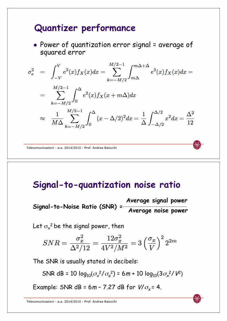
Quantizer performance
! Power of quantization error signal = average ofsquared error
Telecomunicazioni - a.a. 2014/2015 - Prof. Andrea Baiocchi
Signal-to-Noise Ratio (SNR) =
Let %x2 be the signal power, then
The SNR is usually stated in decibels:
SNR dB = 10 log10(#x2/#e
2) = 6m + 10 log10(3#x2/V2)
Example: SNR dB = 6m – 7.27 dB for V/#x = 4.
Signal-to-quantization noise ratio
Average signal power
Average noise power

Telecomunicazioni - a.a. 2014/2015 - Prof. Andrea Baiocchi
Digital Transmission of AnalogInformation
Interpolationfilter
Displayor
playout
2W samples / sec
2W m bits/secx(t)
Bandwidth W
Sampling(A/D)
QuantizationAnalogsource
2W samples / sec m bits / sample
Pulse
generator
y(t)
Original
Approximation
Transmission
or storage
Telecomunicazioni - a.a. 2014/2015 - Prof. Andrea Baiocchi
W = 4 kHz, so Nyquist sampling theorem
& 2W = 8000 samples/second
Suppose error requirement = 1% error
SNR = 10 log10(1/.01)2 = 40 dB
Assume V/#x = 4, then
40 dB = 6m – 7.27 & m = 8 bits/sample
PCM (“Pulse Code Modulation”):
Bit rate= 8000 x 8 bits/sec= 64 kbps
Example: Telephone Speech

Why Digital Communications?
Fundamentals ofcommunications
Adapted from slides of the book:A. Leon Garcia, I. Widjaja, “Communication
networks”, McGraw Hill, 2004
Telecomunicazioni - a.a. 2014/2015 - Prof. Andrea Baiocchi
A Transmission System
Transmitter! Converts information into signal suitable for transmission
! Signal = measurable physical quantity that can be modifiedaccording to the value of the data to be transmitted, conveyed overa transmissin medium and detected by a receiving device.
! Injects energy into communications medium or channel
Receiver! Receives energy from medium! Converts received signal into form suitable for delivery to user
Receiver
Communication channel
Transmitter

Telecomunicazioni - a.a. 2014/2015 - Prof. Andrea Baiocchi
Transmission Impairments
Communication Channel! Pair of copper wires
! Coaxial cable
! Optical fiber
! Radio! Including infrared
Transmission Impairments! Attenuation
! Distortion
! Noise
! Interference
! Timing errors
Transmitted
SignalReceived
Signal Receiver
Communication channel
Transmitter
Telecomunicazioni - a.a. 2014/2015 - Prof. Andrea Baiocchi
Analog vs. Digital Transmission
Analog transmission: all details must be reproduced accurately
Sent
Sent
Received
Received
Distortion
Attenuation
Digital transmission: only discrete levels need to be reproduced
Distortion
AttenuationSimple Receiver:
Was original
pulse positive or
negative?

Telecomunicazioni - a.a. 2014/2015 - Prof. Andrea Baiocchi
Analog Long-Distance Communications
! Each repeater attempts to restore signal to its original form! Attenuation is removed (amplifier)
! Distortion is not completely eliminated
! In-band noise & interference can be removed only in part (out of band)
! Signal quality decreases with # of repeaters
Source DestinationRepeater
Transmission segment
Repeater. . .
Attenuated and
distorted signal + noise
Equalizer
Recovered signal +
residual noiseRepeater
Amp
Telecomunicazioni - a.a. 2014/2015 - Prof. Andrea Baiocchi
Digital Long-Distance Communications
! Regenerator recovers original data (bit) sequence fromdegraded signal and retransmits on next segment byusing a “clean” signal! But timing recovery is required!
! All impairments are “condensed” into bit errors
Source DestinationRegenerator
Transmission segment
Regenerator. . .
Amplifier
equalizer
Timing
recovery
Decision circuit
and signal
regenerator

Telecomunicazioni - a.a. 2014/2015 - Prof. Andrea Baiocchi
Digital Binary Signal
For a given communications medium:! How do we increase transmission speed?! How do we achieve reliable communications?! Are there limits to speed and reliability?
+A
-A
0 T 2T 3T 4T 5T 6T
1 1 1 10 0
Bit rate = 1 bit / T seconds
Signal is meaningless without associated clock
Telecomunicazioni - a.a. 2014/2015 - Prof. Andrea Baiocchi
Clock signal
Message bits
Baseband signalwith NRZ coding
+d
-d
1
0
0 1 0 1 1 0 1 0 0 0 1 1 0
Example of clock
Telecomunicazioni - a.a. 2014/2015 - Prof. Andrea Baiocchi
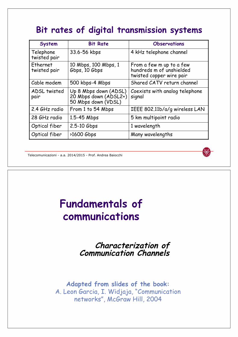
Many wavelengths>1600 GbpsOptical fiber
1 wavelength2.5-10 GbpsOptical fiber
5 km multipoint radio1.5-45 Mbps28 GHz radio
IEEE 802.11b/a/g wireless LANFrom 1 to 54 Mbps2.4 GHz radio
Coexists with analog telephonesignal
Up 8 Mbps down (ADSL)20 Mbps down (ADSL2+)50 Mbps down (VDSL)
ADSL twistedpair
Shared CATV return channel500 kbps-4 MbpsCable modem
From a few m up to a fewhundreds m of unshieldedtwisted copper wire pair
10 Mbps, 100 Mbps, 1Gbps, 10 Gbps
Ethernettwisted pair
4 kHz telephone channel33.6-56 kbpsTelephonetwisted pair
ObservationsBit RateSystem
Bit rates of digital transmission systems
Characterization ofCommunication Channels
Fundamentals ofcommunications
Adapted from slides of the book:A. Leon Garcia, I. Widjaja, “Communication
networks”, McGraw Hill, 2004

Telecomunicazioni - a.a. 2014/2015 - Prof. Andrea Baiocchi
Communications Channels
! A physical medium is an inherent part of acommunications system! Copper wires, radio medium, or optical fiber
! Communications system includes electronic oroptical devices that are part of the pathfollowed by a signal! Transmitter, equalizers, amplifiers, filters, couplers,
detector, clocks and carrier generators
! By communication channel we refer to thecombined end-to-end physical medium andattached devices
Telecomunicazioni - a.a. 2014/2015 - Prof. Andrea Baiocchi
Communication system block scheme
SourceSource
encoder
Channel
encoder
Line
encoder
Modulator &
tx front end
Information source
Channel
Line
decoder
A/D
converter
Rx
front end
Timing
recovery
Channel
decoder
Information
rendering
Final
user
Information destination
Demodulation,
equalization,
symbol decision

Telecomunicazioni - a.a. 2014/2015 - Prof. Andrea Baiocchi
How good is a channel?
! Performance: What is the maximum reliabletransmission speed?! Speed: Bit rate, R bps
! Reliability: Bit error rate, BER=10–k
! Focus of this section
! Cost: What is the cost of alternatives at a given levelof performance?! Wired vs. wireless?
! Electronic vs. optical?
! Standard A vs. standard B?
Telecomunicazioni - a.a. 2014/2015 - Prof. Andrea Baiocchi
Communications Channel
Bandwidth
! In order to transfer datafaster, a signal has to varymore quickly.
! A channel or medium has aninherent limit on how fastthe signals it passes can vary
! Channel bandwidth limitshow tightly input pulses canbe packed
Impairments! Signal attenuation! Signal distortion! Spurious noise! Interference from other
signals! Channel impairments limit
accuracy of measurements onreceived signal
Transmitted
SignalReceived
Signal
ReceiverCommunication channelTransmitter

Telecomunicazioni - a.a. 2014/2015 - Prof. Andrea Baiocchi
Communication channel model
! We often assume two basic properties ofchannels
! Linearity
y1(t)=Ch[x1(t)], y2(t)=Ch[x2(t)] =>
y1(t)+y2(t)=Ch[x1(t)+x2(t)]! Counterexample: amplifiers distorsion
! Stationarity
y1(t)=Ch[x1(t)] => y2(t+d)=Ch[x2(t+d)]
for any d>0.! Counterexample: radiomobile channels
Telecomunicazioni - a.a. 2014/2015 - Prof. Andrea Baiocchi
Channel
t t
x(t) = Aincos(2"ft) y(t) = Aout(f)·cos(2"ft + '(f))
Aout
Ain
A(f) =
Frequency Domain ChannelCharacterization
! Assumption. Channel is linear and stationary! Linear: superposition of effects holds! Stationary: input-output relationship does not vary over time
! Apply sinusoidal input at frequency f! Output is sinusoid at same frequency, but attenuated & phase-
shifted! Sinusoids are autofunctions of LTI systems

Telecomunicazioni - a.a. 2014/2015 - Prof. Andrea Baiocchi
Channel
t t
x(t) = Aincos(2"ft) y(t) = Aout(f)·cos(2"ft + '(f))
Frequency Domain ChannelCharacterization
! Apply sinusoidal input at frequency f! Measure amplitude of output sinusoid (of same frequency f) and
calculate amplitude response A(f) = ratio of output amplitude toinput amplitude! If A(f) " 1, then input signal passes readily! If A(f) " 0, then input signal is blocked
! Bandwidth Wc is range of frequencies passed by channel
H(f) = A(f)·ei'(f)Transfer function:
Telecomunicazioni - a.a. 2014/2015 - Prof. Andrea Baiocchi
Ideal Low-Pass Filter
! Ideal filter: all sinusoids with frequency f<Wc arepassed without attenuation and delayed by ( seconds;sinusoids at other frequencies are blocked
Amplitude Response
f
1
f0
'(f) = –2"f(
1/ 2"
Phase Response
Wc
y(t) = Aincos(2"ft – 2"f() = Aincos(2"f(t – ( )) = x(t–()

Telecomunicazioni - a.a. 2014/2015 - Prof. Andrea Baiocchi
Example: Low-Pass Filter
! Simplest non-ideal circuit that provides low-pass filtering
H(f)=1/(1+i2"bf)! Example: RC circuit, b=R·C.
f
1 A(f) = (1+4"2b2f2)–1/2
Amplitude Response
f0
$(f) = –arctan(2"bf)
-45o
-90o
1/ 2"
Phase Response
Wc
1/" 2
Telecomunicazioni - a.a. 2014/2015 - Prof. Andrea Baiocchi
Example: Bandpass Channel
! Some channels pass signals within a band that excludeslow frequencies! ADSL modems, radio systems, …
! Channel bandwidth is the width of the frequency bandthat passes non-negligible signal power
! Example. 3dB bandwidth: frequency interval whereoutput power density is no less than 1/2 than peak value
f
Amplitude Response
A(f)Wc =f2–f1
f1 f2

Telecomunicazioni - a.a. 2014/2015 - Prof. Andrea Baiocchi
Channel Distortion
! Channel has two effects:! If amplitude response is not flat, then different frequency
components of x(t) will be transferred by different amounts
! If phase response is not linear, then different frequencycomponents of x(t) will be delayed by different amounts
! In either case, the shape of x(t) is altered
! Let x(t) be a digital signal bearing data information
! How well does y(t) follow x(t)?
y(t) = )k A(fk) ak cos(2"fkt + *k + '(fk ))
Channely(t)x(t) = )k akcos(2"fkt + *k)
Telecomunicazioni - a.a. 2014/2015 - Prof. Andrea Baiocchi
Example: Amplitude Distortion
! Let x(t) input to ideal lowpass filter that has zero delayand Wc = 1.5 kHz, 2.5 kHz, or 4.5 kHz
1 0 0 0 0 0 0 1
. . . . . .
t1 ms
x(t)
! Wc = 1.5 kHz passes only the first two terms
! Wc = 2.5 kHz passes the first three terms
! Wc = 4.5 kHz passes the first five terms
f0=1/T=1000 Hz

Telecomunicazioni - a.a. 2014/2015 - Prof. Andrea Baiocchi
-1.5
-1
-0.5
0
0.5
1
1.5
0
0.1
25
0.2
5
0.3
75
0.5
0.6
25
0.7
5
0.8
75 1
-1.5
-1
-0.5
0
0.5
1
1.5
0
0.1
25
0.2
5
0.3
75
0.5
0.6
25
0.7
5
0.8
75 1
-1.5
-1
-0.5
0
0.5
1
1.50
0.1
25
0.2
5
0.3
75
0.5
0.6
25
0.7
5
0.8
75 1
Amplitude Distortion
! As the channelbandwidthincreases, theoutput of thechannel resemblesthe input moreclosely
Telecomunicazioni - a.a. 2014/2015 - Prof. Andrea Baiocchi
Time-domain Characterization
! Time-domain characterization of a channel requiresfinding the impulse response h(t)
! Apply a very narrow pulse of amplitude a to a channelat time ( and observe the channel output at time t
! The output in case of a linear, stationary, causalchannel is
y(t) = 0, t < ( y(t) = a·h(t–(), t > (
Channel
t0t
h(t)
td
a
+(t)
0

Telecomunicazioni - a.a. 2014/2015 - Prof. Andrea Baiocchi
Impulse response
! h(t) is the impulse response of the channel
INPUT OUTPUT
By definition +(t) h(t)
Causality a·+(t) h(t)=0 for t<0
Time invariance +(t–T) h(t–T)
Linearity a·+(t–Ta)+b·+(t–Tb) a·h(t–Ta)+b·h(t–Tb)
! If a signal x(t) is applied to LTI channel input, then
y(t) = # x(()h(t–()d(! x(t) can be thought of as the sum of pulses at times ( (–$< (<$)
with amplitude x((), so y(t) is the sum of responses x(()h(t–()
! It can be shown that H(f) is the Fourier transform ofh(t) and thatY(f) = H(f)X(f)
Telecomunicazioni - a.a. 2014/2015 - Prof. Andrea Baiocchi
Linear, stationary channels andpulse transmission
! Time invariance
! Linearity
! In case of pulse transmission in a linear, timeinvariant, additive noise channel, we get anoutput signal y(t):
y(t) = !k xk h(t–kT) + z(t)
Input Output
xk·+(t–kT) xk·h(t–kT)
#k xk·+(t–kT) #k xk·h(t–kT)
noise

Telecomunicazioni - a.a. 2014/2015 - Prof. Andrea Baiocchi
InterSymbol Interference (ISI)
! By sampling channel output at time nT (perfectsync) we get
yn = y(nT) = %k xk hn–k + zn
with hn–k = h(nT–kT) and zn = z(nT).
yn = xnh0 + %k& n xkhn–k + zn
! ISI is the undesired interference coming from tailsof pulses other than the n-th one and giving non-nullcontributions to the n-th output sample
noise sampleISIuseful term
output
sample
Telecomunicazioni - a.a. 2014/2015 - Prof. Andrea Baiocchi
Nyquist condition for null ISI
! Given a channel response HCH(f), we can addreception and possibly transmission filters, sothat the overall (filtered) channel response is
H(f) = HTX(f) HCH(f) HRX(f)
! To get null ISI at sampling rate 1/T it must be
%k H(f–k/T) = cost
! For a low-pass channel with H(f)=0 for |f|>Wcthis is not possible unless 1/T <= 2Wc.
Max symb rate for zero ISI = 2 x channel bandwidth

Telecomunicazioni - a.a. 2014/2015 - Prof. Andrea Baiocchi
! For channel with ideal low-pass amplitude response ofbandwidth Wc, the impulse response is a Nyquist pulseh(t)=s(t–(), where T =1/(2Wc), and
-0.4
-0.2
0
0.2
0.4
0.6
0.8
1
1.2
-7 -6 -5 -4 -3 -2 -1 0 1 2 3 4 5 6 7t
T T T T T T T T T T T T T T
! s(t) has zero crossings at t = kT, k = ±1, ±2, …
! Pulses can be packed every T seconds with zero Inter-Symbol Interference (ISI)
Nyquist Pulse with Zero ISI
Telecomunicazioni - a.a. 2014/2015 - Prof. Andrea Baiocchi
-2
-1
0
1
2
-2 -1 0 1 2 3 4
tT T T T TT
-1
0
1
-2 -1 0 1 2 3 4
tT T T T TT
Example of composite waveformThree Nyquist pulsesshown separately
! + s(t)
! + s(t-T)
! - s(t-2T)
Composite waveform
r(t) = s(t)+s(t-T)-s(t-2T)
Samples at kT
r(0)=s(0)+s(-T)-s(-2T)=+1
r(T)=s(T)+s(0)-s(-T)=+1
r(2T)=s(2T)+s(T)-s(0)=-1
Zero ISI at samplingtimes kT
r(t)
+s(t) +s(t-T)
-s(t-2T)

Telecomunicazioni - a.a. 2014/2015 - Prof. Andrea Baiocchi
0f
A(f)
Nyquist pulse shapes! If channel is ideal low pass with Wc, then pulses maximum
rate pulses can be transmitted without ISI is 2Wc pulse/s
! s(t) is one example of class of Nyquist pulses with zero ISI! Problem: sidelobes in s(t) decay as 1/t which add up quickly when
there are slight errors in timing
! Raised cosine pulse below has zero ISI! Requires slightly more bandwidth than Wc
! Sidelobes decay as 1/t3, so more robust to timing errors
1
sin(!t/T)
!t/T
cos(!,t/T)
1 – (2,t/T)2
(1–,)Wc Wc (1+,)Wc
Telecomunicazioni - a.a. 2014/2015 - Prof. Andrea Baiocchi
! 10 Gbit/s signalwithout dispersion(negligible ISI)
! 10 Gbit/s signal aftertransmission througha dispersive channel(with non negligibleISI)
Eye diagram

Fundamental Limits in DigitalTransmission
Fundamentals ofcommunications
Adapted from slides of the book:A. Leon Garcia, I. Widjaja, “Communication
networks”, McGraw Hill, 2004
Telecomunicazioni - a.a. 2014/2015 - Prof. Andrea Baiocchi
Transmitter
Filter
Communication
Medium
Receiver
Filter Receiver
r(t)
Received signal
+A
-A0 T 2T 3T 4T 5T
1 1 1 10 0
t
Signaling with Nyquist Pulses
! p(t) pulse at receiver in response to a single input pulse (takes intoaccount pulse shape at input, transmitter & receiver filters, andcommunications medium)
! r(t) waveform that appears in response to sequence of pulses
! If s(t) is a Nyquist pulse, then r(t) has zero intersymbolinterference (ISI) when sampled at multiples ofT

Telecomunicazioni - a.a. 2014/2015 - Prof. Andrea Baiocchi
Multilevel Signaling! Nyquist pulses achieve the maximum signalling rate with
zero ISI! 2Wc pulses per second or 2Wc pulses / Wc Hz = 2 pulses / Hz
! With two signal levels, each pulse carries one bit of thesource bit stream! Bit rate = 2Wc (bit/s)
! With M = 2m signal levels, each pulse carries m bit! Bit rate = 2Wc (pulse/s) · m (bit/pulse) = 2Wcm (bit/s)
In the absence of noise, the bit rate can be increasedwithout limit by increasing m
BUTAdditive noise limits # of levels that can be used reliably.
Telecomunicazioni - a.a. 2014/2015 - Prof. Andrea Baiocchi
Example of Multilevel Signaling
! Four levels {-1, -1/3, 1/3, +1} for {00,01,10,11}
! Waveform for 11,10,01 sends +1, +1/3, -1/3
! Zero ISI at sampling instants
-0.6
-0.4
-0.2
0
0.2
0.4
0.6
0.8
1
1.2
-1 0 1 2 3
Composite waveform

Telecomunicazioni - a.a. 2014/2015 - Prof. Andrea Baiocchi
Noise & Reliable Communications
! All physical systems have noise! Electrons always vibrate at non-zero temperature:
motion of electrons induces noise
! Presence of noise limits accuracy ofmeasurement of received signal amplitude
! Errors occur if signal separation is comparableto noise level
! Noise places a limit on how many amplitudelevels can be used in pulse transmission
Telecomunicazioni - a.a. 2014/2015 - Prof. Andrea Baiocchi
Four signal levels Eight signal levels
Noise Limits Accuracy! Receiver makes decision based on (sampled) received
signal level = source pulse level + noise! Error rate depends on relative value of noise amplitude and
spacing between signal levels
! Large (positive or negative) noise values can cause wrong decision
Typical noise
+A
+A/3
-A/3
-A
+A
+5A/7
+3A/7
+A/7
-A/7
-3A/7
-5A/7
-A
Decision thresholds

Telecomunicazioni - a.a. 2014/2015 - Prof. Andrea Baiocchi
Noise! Noise signal is usually a zero-mean process z(t)
characterized by! probability distribution of amplitude samples, i.e.
Pr(z(t) > u)
! Time auto-correlation, i.e. Rzz(t)=E[z(h)z(h+t)]
! Thermal electronic noise is inevitable (due tovibrations of electrons); thermal Noise can bemodeled as a “white” Gaussian process! Probability distribution is Gaussian zero mean
! Time auto-correlation is a Dirac pulse at 0
! Often interference from a large number ofscattered and similar sources can be modeledas white Gaussian “noise”
Telecomunicazioni - a.a. 2014/2015 - Prof. Andrea Baiocchi
22
2
2
1 !
!"
xe#
x0
Gaussian noise
t
x
Pr(X(t)>x0) = area under graph on the right of x0
x0
x0
%2 = Avg Noise Power

Telecomunicazioni - a.a. 2014/2015 - Prof. Andrea Baiocchi
Probability of Error! Error occurs if noise value exceeds the
information signal magnitude over the decisionthreshold
! With two-level signalling, +A and –A, probabilityof error is Q(A/%)
1.00E-121.00E-11
1.00E-101.00E-091.00E-08
1.00E-071.00E-061.00E-05
1.00E-041.00E-031.00E-02
1.00E-011.00E+00
0 2 4 6 8
x
Q(x)
Telecomunicazioni - a.a. 2014/2015 - Prof. Andrea Baiocchi
Role of SNR
! With M=2m levels per symbol, the tx symbolvalues are ak=–A+(2k–1)A/M, with k=1,…,M.
! With equiprobable symbols:E[ak
2]=(M2–1)A2/(3M2)=PTX
! Received sample is (dispersive channel, zeroISI): yn=h0xn+zn.

Telecomunicazioni - a.a. 2014/2015 - Prof. Andrea Baiocchi
signal noise signal + noise
signal noise signal + noise
High
SNR
Low
SNR
SNR = Average Signal Power
Average Noise Power
SNR (dB) = 10 log10 SNR
virtually error-free
error-prone
Channel Noise affects Reliability
Telecomunicazioni - a.a. 2014/2015 - Prof. Andrea Baiocchi
! If transmitted power is limited, then as M increasesspacing between levels decreases
! Presence of noise at receiver causes more frequenterrors to occur as M is increased
Shannon Channel Capacity:! The maximum reliable transmission rate over an AWGN
bandlimited channel with bandwidth Wc Hz is
Cb = Wc log2(1+SNR) bit/s
Shannon Channel Capacity
X
Input symbol
(Gaussian)
Y=X+Z
Output symbol
Z
White gaussian noise
2Wc symbols/s
Bandlimited channel (Wc)
Telecomunicazioni - a.a. 2014/2015 - Prof. Andrea Baiocchi
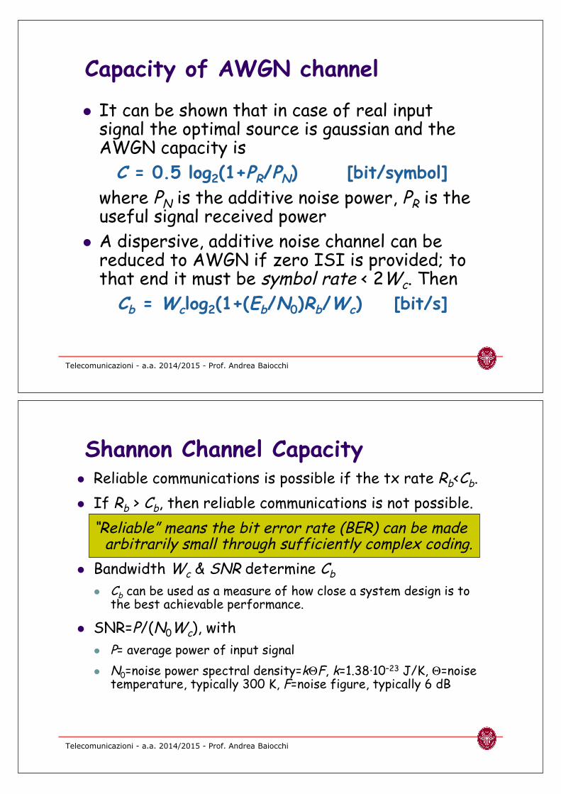
Capacity of AWGN channel
! It can be shown that in case of real inputsignal the optimal source is gaussian and theAWGN capacity is
C = 0.5 log2(1+PR/PN) [bit/symbol]
where PN is the additive noise power, PR is theuseful signal received power
! A dispersive, additive noise channel can bereduced to AWGN if zero ISI is provided; tothat end it must be symbol rate < 2Wc. Then
Cb = Wclog2(1+(Eb/N0)Rb/Wc) [bit/s]
Telecomunicazioni - a.a. 2014/2015 - Prof. Andrea Baiocchi
! Reliable communications is possible if the tx rate Rb<Cb.
! If Rb > Cb, then reliable communications is not possible.
“Reliable” means the bit error rate (BER) can be madearbitrarily small through sufficiently complex coding.
! Bandwidth Wc & SNR determine Cb
! Cb can be used as a measure of how close a system design is tothe best achievable performance.
! SNR=P/(N0Wc), with
! P= average power of input signal
! N0=noise power spectral density=k-F, k=1.38·10–23 J/K, -=noisetemperature, typically 300 K, F=noise figure, typically 6 dB
Shannon Channel Capacity

Telecomunicazioni - a.a. 2014/2015 - Prof. Andrea Baiocchi
Example
! Find the Shannon channel capacity for a telephonechannel with Wc = 3400 Hz and SNR = 10000
C = 3400 log2 (1 + 10000)
= 3400 log10 (10001)/log102 = 45200 bps
Note that SNR = 10000 corresponds to
SNR (dB) = 10 log10(10000) = 40 dB
Modems and Digital Modulation
Fundamentals ofcommunications
Adapted from slides of the book:A. Leon Garcia, I. Widjaja, “Communication
networks”, McGraw Hill, 2004

Telecomunicazioni - a.a. 2014/2015 - Prof. Andrea BaiocchiTanenbaum, Wetherall, Reti di calcolatori © Pearson 201283
Codifiche di linea: (a) Bit, (b) NRZ, (c)NRZI, (d) Manchester, (e) Bipolare o AMI.
Telecomunicazioni - a.a. 2014/2015 - Prof. Andrea Baiocchi
Bandpass Channels
! Bandpass channels pass a range of frequencies aroundsome center frequency fc
! Radio channels, telephone & DSL modems
! Digital modulators embed information into waveformwith frequencies passed by bandpass channel! A sinusoidal signal with frequency fc centered in middle of
bandpass channel is named carrier
! Modulators embed information into the carrier
fc – Wc/2 fc0 fc + Wc/2

Telecomunicazioni - a.a. 2014/2015 - Prof. Andrea BaiocchiTanenbaum, Wetherall, Reti di calcolatori © Pearson 201285
(a) Un segnale binario. (b) Modulazione diampiezza. (c) Modulazione di frequenza.(d) Modulazione di fase.
Telecomunicazioni - a.a. 2014/2015 - Prof. Andrea Baiocchi
Information 1 1 1 10 0
+1
-10 T 2T 3T 4T 5T 6T
Amplitude
Shift
Keying
+1
-1
Frequency
Shift
Keying 0 T 2T 3T 4T 5T 6T
t
t
Amplitude Modulation andFrequency Modulation
Map bits into amplitude of sinusoid: “1” send sinusoid; “0” no sinusoid
Demodulator looks for signal vs. no signal
Map bits into frequency: “1” send frequency fc + + ; “0” send frequency fc - +
Demodulator looks for power around fc + + or fc - +

Telecomunicazioni - a.a. 2014/2015 - Prof. Andrea Baiocchi
Phase Modulation
! Map bits into phase of sinusoid:! “1” send A cos(2"ft) , i.e. phase is 0
! “0” send A cos(2"ft+") , i.e. phase is "
! Equivalent to multiplying cos(2"ft) by +A or -A! “1” send A cos(2"ft) , i.e. multiply by 1
! “0” send A cos(2"ft+") = - A cos(2"ft) , i.e. multiply by -1
+1
-1
Phase
Shift
Keying 0 T 2T 3T 4T 5T 6T t
Information 1 1 1 10 0
Telecomunicazioni - a.a. 2014/2015 - Prof. Andrea Baiocchi
Modulate cos(2"fct) by multiplying by Ak for T seconds:
Akx
cos(2"fct)
Y(t) = Ak cos(2"fct), kT<t<(k+1)T
Transmitted signal
during kth interval
Modulator

Telecomunicazioni - a.a. 2014/2015 - Prof. Andrea Baiocchi
Demodulator
Demodulate (recover Ak) by multiplying by 2cos(2"fct)
for T seconds and lowpass filtering (smoothing):
x
2cos(2"fct)2Ak cos2(2"fct) = Ak {1 + cos(2"2fct)}
Lowpass
Filter
(Smoother)
X(t)Y(t) = Akcos(2"fct)
Received signal
during kth interval
Multiplication for the local carrier and integration over a
symbol interval takes place for every symbol
Synchronous demodulation
(perfect local carrier)
Telecomunicazioni - a.a. 2014/2015 - Prof. Andrea Baiocchi
1 1 1 10 0
+A
-A0 T 2T 3T 4T 5T 6T
Information
Baseband
Signal
Modulated
Signal
x(t)
+A
-A0 T 2T 3T 4T 5T 6T
Example of Modulation
A cos(2"ft) -A cos(2"ft)

Telecomunicazioni - a.a. 2014/2015 - Prof. Andrea Baiocchi
1 1 1 10 0Recovered
Information
Baseband
signal discernable
after smoothing
After multiplication
at receiverx(t) cos(2"fct)
+2A
–2A
0 T 2T 3T 4T 5T 6T
+A
-A0 T 2T 3T 4T 5T 6T
Example of DemodulationA {1 + cos(4"fct)} -A {1 + cos(4"fct)}
Telecomunicazioni - a.a. 2014/2015 - Prof. Andrea Baiocchi
Signaling rate andTransmission Bandwidth! Fact from modulation theory:
Baseband signal x(t)
with bandwidth B Hz
If
then B
fc+B
f
f
fc-B fc
Modulated signalx(t)cos(2"fct) has
bandwidth 2B Hz
! If bandpass channel has bandwidth Wc Hz,! Then baseband channel has Wc/2 Hz available, so modulation
system supports Wc/2 x 2 = Wc pulses/second
! That is, Wc pulse/s per Wc Hz = 1 pulse/Hz
! Recall baseband transmission system supports 2 pulses/Hz

Telecomunicazioni - a.a. 2014/2015 - Prof. Andrea Baiocchi
Akx
cos(2"fct)
Yi(t) = Ak cos(2"fct)
Bkx
sin(2"fct)
Yq(t) = Bk sin(2"fct)
+ Y(t)
! Yi(t) and Yq(t) both occupy the bandpass channel
! QAM sends 2 pulses/Hz
Quadrature Amplitude Modulation (QAM)
! QAM uses two-dimensional signaling! Ak modulates in-phase cos(2"fct)
! Bk modulates quadrature phase cos(2"fct + "/2) = sin(2"fct)
Transmitted
Signal
Telecomunicazioni - a.a. 2014/2015 - Prof. Andrea Baiocchi
QAM Demodulation
Y(t) x
2cos(2!fct)2Ak cos2(2!fct)+2Bk cos(2!fct)sin(2!fct)
= Ak [1 + cos(4!fct)]+Bk sin(4!fct)
= Ak + [Ak cos(4!fct)+Bk sin(4!fct)]
Lowpass
filter
(smoother)
Ak
2Bk sin2(2!fct)+2Ak cos(2!fct)sin(2!fct)
= Bk [1 – cos(4!fct)]+Ak sin(4!fct)
= Bk – [Bk cos(4!fct) – Ak sin(4!fct)]
x
2sin(2!fct)
Bk
Lowpass
filter
(smoother)
smoothed to zero
smoothed to zero

Telecomunicazioni - a.a. 2014/2015 - Prof. Andrea Baiocchi
Complex numbers
! Tx signal with in-phase and quad modulation is
x(t) = Akcos(2"fct)+Bksin(2"fct)
! Let Ck=Ak+iBk; then
x(t) = Re[Ckexp(–i2"fct)]
! We can now generalize to any alphabet ofcomplex symbols to code information bits.! E.g. in case of polar coordinates:
Re[Mkexp(–i'k)exp(–i2"fct)] = Mkcos(2"fct+'k)
! This is phase modulation ifMk is a constant or mixedamplitude and phase modulation in the general case(QAM)
Telecomunicazioni - a.a. 2014/2015 - Prof. Andrea Baiocchi
Signal Constellations
! Each pair (Ak, Bk) defines a point in the plane
! Signal constellation set of signaling points
4 possible points per T s
2 bits / pulse
Ak
Bk
16 possible points per T s
4 bits / pulse
Ak
Bk
(A, A)
(A,-A)(-A,-A)
(-A,A)

Telecomunicazioni - a.a. 2014/2015 - Prof. Andrea Baiocchi
Ak
Bk
4 possible points per T s
Ak
Bk
16 possible points per T s
Other Signal Constellations
! Point selected by amplitude & phase
Telecomunicazioni - a.a. 2014/2015 - Prof. Andrea BaiocchiTanenbaum, Wetherall, Reti di calcolatori © Pearson 201298
(a) QPSK. (b) QAM-16. (c) QAM-64

Telecomunicazioni - a.a. 2014/2015 - Prof. Andrea BaiocchiTanenbaum, Wetherall, Reti di calcolatori © Pearson 201299
Codifica di Gray per QAM-16
Telecomunicazioni - a.a. 2014/2015 - Prof. Andrea Baiocchi
Signal constellations and errors

Properties of Media and DigitalTransmission Systems
Fundamentals ofcommunications
Adapted from slides of the book:A. Leon Garcia, I. Widjaja, “Communication
networks”, McGraw Hill, 2004
Telecomunicazioni - a.a. 2014/2015 - Prof. Andrea Baiocchi
Fundamental Issues in TransmissionMedia
! Information bearing capacity! Amplitude response & bandwidth
! Susceptibility to noise & interference
! Propagation speed of signal! c = 3 x 10⁸ m/s in vacuum
! . = c/"/ speed of light in medium where />1 is the dielectricconstant of the medium
! . = 2.3 x 10⁸ m/s in copper wire; . = 2.0 x 10⁸ m/s in optical fiber
t = 0t = d/c
Communication channel
d meters

Telecomunicazioni - a.a. 2014/2015 - Prof. Andrea Baiocchi
Wireless & Wired Media
Wireless Media
! Signal energy propagatesin space, limiteddirectionality
! Interference possible,so spectrum regulated
! Limited bandwidth
! Simple infrastructure:antennas & transmitters
! User/terminal can move
Wired Media
! Signal energy contained& guided within medium
! Spectrum can be re-usedin separate media (wiresor cables), more scalable
! Extremely highbandwidth
! Complex infrastructure:ducts, conduits, poles,right-of-way
Telecomunicazioni - a.a. 2014/2015 - Prof. Andrea Baiocchi
Communications systems &Electromagnetic Spectrum
! Frequency of communications signals
Analog
telephoneDSL Cell
phone
WiFiOptical
fiber
102 104 106 108 1010 1012 1014 1016 1018 1020 1022 1024
Frequency (Hz)
Wavelength (meters)
106 104 102 10 10-2 10-4 10-6 10-8 10-10 10-12 10-14
Pow
er
and
tele
phone
Bro
adcast
radio
Mic
row
ave
radio
Infr
are
d lig
ht
Vis
ible
lig
ht
Ultra
vio
let lig
ht
X-r
ays
Gam
ma r
ays

Telecomunicazioni - a.a. 2014/2015 - Prof. Andrea Baiocchi
Attenuation
! Attenuation varies with medium! Dependence on distance of central importance
! Wired media has exponential dependence! Received power at d meters proportional to 10–0d
! Attenuation in dB = 0d, where 0 is dB/meter
! Wireless media has logarithmic dependence! Received power at d meters proportional to d-n
! Attenuation in dB = n log d, where n is path lossexponent; n=2 in free space
Telecomunicazioni - a.a. 2014/2015 - Prof. Andrea BaiocchiTanenbaum, Wetherall, Reti di calcolatori © Pearson 2012106
(a) Nelle bande VLF, LF ed MF le onde radioseguono la curvatura del pianeta.(b) Nella banda HF rimbalzano contro laionosfera.

Telecomunicazioni - a.a. 2014/2015 - Prof. Andrea Baiocchi
Source: Motorola
1 KHz 1 MHz 1 GHz
AudioFrequencies
Short-Wave Radio
AM Broad-cast
FM Broadcast
Television Telecommunications
Cellular Telephone,SMR, Packet Radio
PCS
Extremely Low
Ve
ry L
ow
Me
diu
m
Lo
w
Hig
h
Ve
ry H
igh
Ultra
Hig
h
Infrared
Vis
ible
Lig
ht
Ultra
Vio
let
X-rays
Co
sm
ic R
ays
Ga
mm
a R
ays
Microwave
2.4 GHz ISM (Industrial Scientific, Medical)
Band
1 THz
Spectrum allocation
Telecomunicazioni - a.a. 2014/2015 - Prof. Andrea BaiocchiTanenbaum, Wetherall, Reti di calcolatori © Pearson 2012108
Bande ISM e U-NII utilizzate daidispositivi wireless negli Stati Uniti.

Telecomunicazioni - a.a. 2014/2015 - Prof. Andrea Baiocchi
Radio spectrum allocated to UMTS
! Frequency Division Duplex.
! 1920-1980 for Uplink.(12x5MHz)
! 2110-2170 for Downlink.(12x5Mhz)
! Time Division Duplex.
! 1900-1920 (4x5Mhz)
! 2010-2025 (3x5Mhz)
Telecomunicazioni - a.a. 2014/2015 - Prof. Andrea Baiocchi
Examples
Cellular Phone! Allocated (licensed) spectrum! First generation:
! 800, 900 MHz! Initially analog voice
! Second generation:! 1800-1900 MHz! Digital voice, messaging
Wireless LAN! Unlicenced ISM spectrum
! Industrial, Scientific, Medical! 902-928 MHz, 2.400-2.4835
GHz, 5.725-5.850 GHz! IEEE 802.11 LAN standard
! 11-54 Mbps
Point-to-Multipoint Systems! Directional antennas at
microwave frequencies! High-speed digital
communications between sites! High-speed Internet Access
Radio backbone links for ruralareas
Satellite Communications! Geostationary satellite @
36000 km above equator! Relays microwave signals from
uplink frequency to downlinkfrequency
! Long distance telephone! Satellite TV broadcast

Telecomunicazioni - a.a. 2014/2015 - Prof. Andrea Baiocchi
Wireless Internet Service Provider
UMTS Operator
Node B
•• UTRAN UTRAN
RNC
UMTS
IPv4 Core Network
GGSN
SGSN
Node B
IPv4 over WAN
•• Wireless LANs IEEE 802.11Wireless LANs IEEE 802.11
Server farm and IMS WWW
….,
Diameter
SIP proxy
Dynamic DNS
….
,
Signaling
Gateway
Profiles
DBs
IPv4 backbone
UMTS: (3GPP)
MM: Ad-Hoc Protocols
AA: Ad-Hoc Protocols
WLAN: (IETF)
MM: Mobile IP, Cellular IP, etc…
AA: User Name/Pwd
Current 3G scenario
Telecomunicazioni - a.a. 2014/2015 - Prof. Andrea Baiocchi
Twisted PairTwisted pair
! Two insulated copper wiresarranged in a regular spiralpattern to minimizeinterference
! Various thicknesses, e.g.0.016 inch (24 gauge)
! Low cost
! Telephone subscriber loopfrom customer to CO
! Intra-building telephonefrom wiring closet todesktop
! LAN cabling (Fast Ethernet,GbE)
Att
en
ua
tio
n (
dB
/mi)
f (kHz)
19 gauge
22 gauge
24 gauge
26 gauge
6
12
18
24
30
110 100 1000
Lower
attenuation rate
analog telephone
Higher
attenuation rate
for DSL

Telecomunicazioni - a.a. 2014/2015 - Prof. Andrea Baiocchi
Twisted Pair Bit Rates
! Twisted pairs can providehigh bit rates at shortdistances
! Asymmetric DigitalSubscriber Loop (ADSL)! High-speed Internet Access! Above 28 kHz
! Much higher rates possible atshorter distances! Strategy for telephone
companies is to bring fiberclose to home & then twistedpair
! Higher-speed access + video
Data rates of 24-gauge twisted pair
1000 feet,300 m
51.840Mbps
STS-1
3000 feet,0.9 km
25.920Mbps
1/2 STS-1
4500 feet,1.4 km
12.960Mbps
1/4 STS-1
12,000 feet,3.7 km
6.312Mbps
DS2
18,000 feet,5.5 km
1.544Mbps
T-1
DistanceDataRateStandard
Telecomunicazioni - a.a. 2014/2015 - Prof. Andrea Baiocchi
Ethernet LANs! Category 3 unshielded twisted pair (UTP):
ordinary telephone wires! Category 5 UTP: tighter twisting to improve
signal quality! Shielded twisted pair (STP): to minimize
interference; costly! 10BASE-T Ethernet
! 10 Mbps, Baseband, Twisted pair! Two Cat3 pairs! Manchester coding, 100 meters
! 100BASE-T4 Fast Ethernet! 100 Mbps, Baseband, Twisted pair! Four Cat3 pairs! Three pairs for one direction at-a-time! 100/3 Mbps per pair;! 3B6T line code, 100 meters
! Cat5 & STP provide other options
! ! ! ! ! !

Telecomunicazioni - a.a. 2014/2015 - Prof. Andrea Baiocchi
Coaxial Cable
! Cylindrical outer conductorsurrounds insulated innerwire conductor
! High interference immunity
! Higher bandwidth thantwisted pair
! Hundreds of MHz
! Cable TV distribution
! Long distance telephonetransmission
! Original Ethernet LANmedium
35
30
10
25
20
5
15
Att
en
ua
tio
n (
dB
/km
)
0.1 1.0 10 100
f (MHz)
2.6/9.5 mm
1.2/4.4 mm
0.7/2.9 mm
Telecomunicazioni - a.a. 2014/2015 - Prof. Andrea Baiocchi
Optical Fiber
! Light sources (lasers, LEDs) generate pulses of light that aretransmitted on optical fiber! Very long distances (>1000 km)
! Very high speeds ( up ro 40 Gbps/wavelength)
! Nearly error-free (BER of 10-15)
! Profound influence on network architecture! Dominates long distance transmission
! Distance less of a cost factor in communications
! Plentiful bandwidth for new services
Optical fiber
Optical
source
ModulatorElectrical
signalReceiver
Electrical
signal
Telecomunicazioni - a.a. 2014/2015 - Prof. Andrea BaiocchiTanenbaum, Wetherall, Reti di calcolatori © Pearson 2012117
(a) Vista laterale di una singolafibra.(b) Vista frontale di una guaina contre fibre.
Telecomunicazioni - a.a. 2014/2015 - Prof. Andrea Baiocchi
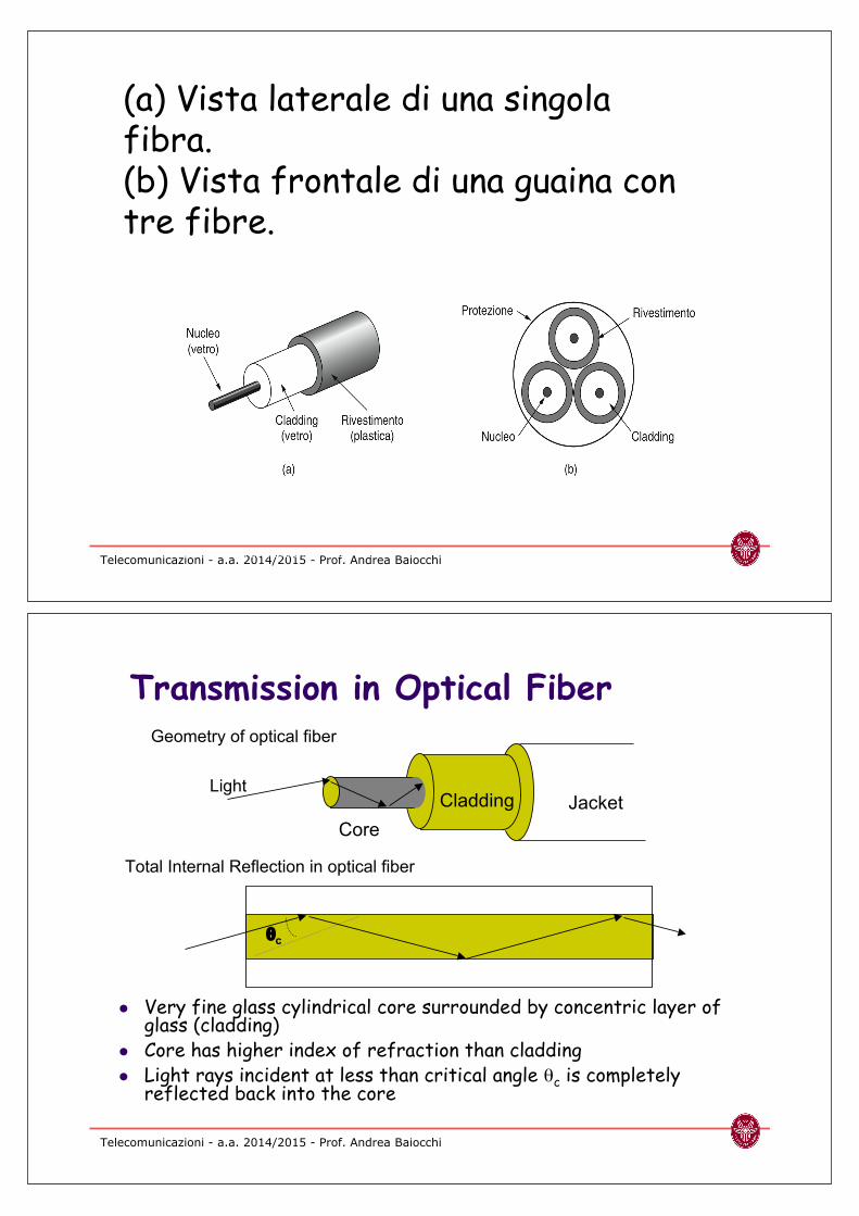
Core
Cladding JacketLight
1c
Geometry of optical fiber
Total Internal Reflection in optical fiber
Transmission in Optical Fiber
! Very fine glass cylindrical core surrounded by concentric layer ofglass (cladding)
! Core has higher index of refraction than cladding! Light rays incident at less than critical angle 1c is completely
reflected back into the core

Telecomunicazioni - a.a. 2014/2015 - Prof. Andrea Baiocchi
! Multimode: Thicker core, shorter reach! Rays on different modes interfere causing dispersion & limiting bit rate
! Single mode: Very thin core supports only one mode! More expensive lasers, but achieves very high speeds
Multimode fiber: multiple rays follow different paths
Single-mode fiber: only direct path propagates in fiber
Direct path
Reflected path
Multimode & Single-mode Fiber
Telecomunicazioni - a.a. 2014/2015 - Prof. Andrea Baiocchi
Optical Fiber Properties
Advantages
! Very low attenuation
! Immunity to external e.minterference
! Extremely high bandwidth
! Security: Very difficult totap without breaking
! No corrosion
! More compact & lighter thancopper wire
! Wideband optical amplifiersavailable (EDFA, SOA)
Disadvantages
! New types of optical signalimpairments & dispersion
! Shot noise
! Polarization dependence
! Non linear effects
! Limited bend radius
! If physical arc of cable toohigh, light lost or won’t reflect
! Will break
! Difficult to splice
! Mechanical vibration becomessignal noise

Telecomunicazioni - a.a. 2014/2015 - Prof. Andrea Baiocchi
100
50
10
5
1
0.5
0.1
0.05
0.010.8 1.0 1.2 1.4 1.6 1.8
Wavelength (µm)
Lo
ss (
dB
/km
)
Infrared absorption
Rayleigh scattering
Very Low Attenuation
850 nm
Low-cost
LEDs LANs
1300 nm
Metropolitan Area
Networks: “Short Haul”
1550 nm
Long Distance
Networks: “Long Haul”
Water Vapor Absorption
(removed in new fiber
designs)
Telecomunicazioni - a.a. 2014/2015 - Prof. Andrea Baiocchi
100
50
10
5
1
0.5
0.1
0.8 1.0 1.2 1.4 1.6 1.8
Lo
ss (
dB
/km
)
Huge Available Bandwidth
! Optical range from 21 to21+#2 contains bandwidth
! Example: 21 = 1450 nm21+#2 =1650 nm:
B = ! 19 THz
B = f1 – f2 = – v
21+#2
v
21
v #221
2= !#2/21
1 + #2/21
v
21
2(108)m/s 200nm
(1450 nm)2

Telecomunicazioni - a.a. 2014/2015 - Prof. Andrea Baiocchi
Wavelength Division Multiplexing
! Different wavelengths carry separate signals
! Multiplex into shared optical fiber
! Each wavelength like a separate circuit
! A single fiber can carry 160 wavelengths, 10 Gbps perwavelength: 1.6 Tbps!
21
22
2m
optical
mux
21
22
2m
optical
demux
21 22. 2m
optical
fiber
Telecomunicazioni - a.a. 2014/2015 - Prof. Andrea Baiocchi
Coarse & Dense WDM
Coarse WDM
! Few wavelengths 4-8with very wide spacing
! Low-cost, simple
Dense WDM
! Many tightly-packedwavelengths
! ITU Grid: 0.8 nmseparation for 10Gbpssignals
! 0.4 nm for 2.5 Gbps
15
50
15
60
15
40
Telecomunicazioni - a.a. 2014/2015 - Prof. Andrea Baiocchi
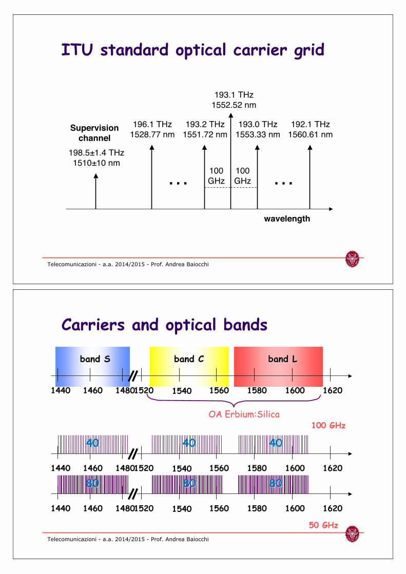
193.1 THz
1552.52 nm
wavelength
196.1 THz
1528.77 nm
193.2 THz
1551.72 nm
193.0 THz
1553.33 nm
192.1 THz
1560.61 nm
100
GHz
100
GHz… …
198.5±1.4 THz
1510±10 nm
Supervision
channel
ITU standard optical carrier grid
Telecomunicazioni - a.a. 2014/2015 - Prof. Andrea Baiocchi
band Sband S band Cband C band Lband L
OA OA ErbiumErbium::SilicaSilica100 100 GHzGHz
50 50 GHzGHz
4040 40404040
80808080 8080
1440 162015801560154015201460 16001480
1440 162015801560154015201460 16001480
1440 162015801560154015201460 16001480
Carriers and optical bands

Telecomunicazioni - a.a. 2014/2015 - Prof. Andrea Baiocchi
! Attenuation
! Dispersion: chromatic (guide + material), polarization(PMD)
! Non linear effect: Brillouin, Raman, Kerr (Self-PhaseModulation (SPM), Cross-Phase Modulation (CPM),Four Wave Mixing (FWM))
! Launched power of 20'mW (13 dBm) in the cross section of amonomodal fiber (50 (m2) corresponds to 40 kW/cm2.
! Crosstalk in (D)WDM systems
! Noise of optical amplifiers (ASE)
! Laser phase noise
Transmission impairments of o.f.
Telecomunicazioni - a.a. 2014/2015 - Prof. Andrea Baiocchi
! Optical fiber response to an input pulse x(t) is the sumof two terms:! a linear dispersive term yL(t) = #x(()h(t–()d(! an instantaneous cubic non linear term yNL(t) = Ax3(t)
! Let x(t) be the sum of three sinusoidal terms withfrequencies f1, f2, f3! Model for DWDM channels (extremely narrowband!!!)
! Besides linear terms, at the output we can findsinusoidal signals at frequencies ±f1±f2±f3! Part of these spurious harmonics falls within signal band
OAOA
Low dispersion fiberLow dispersion fiberinput output
Four Wave Mixing

Telecomunicazioni - a.a. 2014/2015 - Prof. Andrea Baiocchi
Power spectrum of an 8x10 Gbps DWDM signal with UnequalChannel Spacing after 50 km of G.653 fiber (2 mW/ch).
Effect of FWM
Telecomunicazioni - a.a. 2014/2015 - Prof. Andrea Baiocchi
Standard fiber (G.652)

Telecomunicazioni - a.a. 2014/2015 - Prof. Andrea Baiocchi
Dispersion shifted fiber (G.653)
Telecomunicazioni - a.a. 2014/2015 - Prof. Andrea Baiocchi
Non-zero dispersion fiber (G.655)

Telecomunicazioni - a.a. 2014/2015 - Prof. Andrea Baiocchi
Regenerators & Optical Amplifiers
! The maximum span of an optical signal is determined bythe available power & the attenuation:! If 30 dB attenuation are allowed, then at 1550 nm, optical
signal attenuates at 0.25 dB/km, so max span = 30 dB/0.25km/dB = 120 km
! Optical amplifiers increase optical signal power (noequalization, no regeneration): Pout=G•Pin+PASE.! Noise is added by each amplifier
! SNRout < SNRin, so there is a limit to the number of OAs in anoptical path
! Optical signal must be regenerated when this limit isreached! Requires optical-to-electrical (O-to-E) signal conversion,
equalization, detection and retransmission (E-to-O)
! Expensive
Telecomunicazioni - a.a. 2014/2015 - Prof. Andrea Baiocchi
Regenerator
R R R R R R R R
DWDM
multiplexer
… …R
R
R
R
…R
R
R
R
…R
R
R
R
…R
R
R
R
…
DWDM & Regeneration
! Single signal per fiber requires 1 regenerator per span
! DWDM system carries many signals in one fiber
! At each span, a separate regenerator required per signal
! Very expensive

Telecomunicazioni - a.a. 2014/2015 - Prof. Andrea Baiocchi
R
R
R
R
Optical
amplifier
… … …R
R
R
R
OA OA OA OA… …
Optical Amplifiers
! Optical amplifiers can amplify the composite DWDMsignal without demuxing or O-to-E conversion
! Erbium Doped Fiber Amplifiers (EDFAs) boost DWDMsignals within 1530 to 1620 range
! Spans between regeneration points >1000 km
! Number of regenerators can be reduced dramatically withdramatic reduction in cost of long-distance communications
Access networks
Fundamentals ofcommunications

Telecomunicazioni - a.a. 2014/2015 - Prof. Andrea BaiocchiTanenbaum, Wetherall, Reti di calcolatori © Pearson 2012137
Ampiezza di banda e distanza perUTP di categoria 3 usati da DSL.
Telecomunicazioni - a.a. 2014/2015 - Prof. Andrea BaiocchiTanenbaum, Wetherall, Reti di calcolatori © Pearson 2012138
ADSL che sfrutta DMT

Telecomunicazioni - a.a. 2014/2015 - Prof. Andrea BaiocchiTanenbaum, Wetherall, Reti di calcolatori © Pearson 2012139
Una configurazione ADSL tipica
Telecomunicazioni - a.a. 2014/2015 - Prof. Andrea BaiocchiTanenbaum, Wetherall, Reti di calcolatori © Pearson 2012140
FttH con fibra ottica passiva

Telecomunicazioni - a.a. 2014/2015 - Prof. Andrea BaiocchiTanenbaum, Wetherall, Reti di calcolatori © Pearson 2012141
(a) Le frequenze non sono riutilizzate nelle celle adiacenti.(b) Per aumentare il numero di utenti si possono utilizzarecelle più piccole.
Telecomunicazioni - a.a. 2014/2015 - Prof. Andrea BaiocchiTanenbaum, Wetherall, Reti di calcolatori © Pearson 2012142
Architettura di rete GSM

Error Detection and Correction
Fundamentals ofcommunications
Adapted from slides of the book:A. Leon Garcia, I. Widjaja, “Communication
networks”, McGraw Hill, 2004
Telecomunicazioni - a.a. 2014/2015 - Prof. Andrea Baiocchi
Error Control
! Digital transmission systems introduce errors
! Applications require certain reliability level
! Data applications require error-free transfer
! Voice & video applications tolerate some errors, the less themore source coding removes redundancy from original signal
! Error control used when transmission system does notmeet application requirement
! Two basic approaches:
Error detection & retransmission (ARQ)
Forward error correction (FEC)

Telecomunicazioni - a.a. 2014/2015 - Prof. Andrea Baiocchi
Key Idea
! All transmitted data blocks (“codewords”) satisfy apattern
! If received block doesn’t satisfy pattern, it is in error
! If it satisfies pattern, it is assumed to be correct
! Redundancy: Only a subset of all possible blocks can becodewords
! Example: in the set of all possible strings made of alphabetcharacters of length less or equal to 20 chars (to make the setfinite), current English dictionary words are “codewords”
ChannelEncoderUser
information
Pattern
checking
All inputs to channel
satisfy pattern or condition
Channel
output
Deliver user
information or
set error alarm
Telecomunicazioni - a.a. 2014/2015 - Prof. Andrea Baiocchi
Codewords communication
All n-bit strings
2n
2k
n-bit strings thatare codewords
All n-bit strings
2n
2k
TX RX
Transfer of a givencodeword, received
as a corruptedstring

Telecomunicazioni - a.a. 2014/2015 - Prof. Andrea Baiocchi
Single Parity Check! Given a data block of k bits, add one more bit so as to
make the number of 1’s even! Same as making 0 the xor of the coded (k+1)-bit block
Info Bits: b1, b2, b3, …, bk
Check Bit: bk+1 = b13b23b33 …3bk
Codeword: (b1, b2, b3, …, bk,, bk+1)
! Receiver checks to see if # of 1’s is even! All error patterns that change an odd # of bits are detectable;
all even-numbered patterns are undetectable
! Parity bit used in ASCII code
Telecomunicazioni - a.a. 2014/2015 - Prof. Andrea Baiocchi
Example of Single Parity Code
! Information (7 bits): (0, 1, 0, 1, 1, 0, 0)
! Parity Bit: b8 = 0 + 1 +0 + 1 +1 + 0 = 1
! Codeword (8 bits): (0, 1, 0, 1, 1, 0, 0, 1)
! If single error in bit 3 : (0, 1, 1, 1, 1, 0, 0, 1)! # of 1’s =5, odd
! Error detected
! If errors in bits 3 and 5: (0, 1, 1, 1, 0, 0, 0, 1)! # of 1’s =4, even
! Error not detected

Telecomunicazioni - a.a. 2014/2015 - Prof. Andrea Baiocchi
How good is the single parity checkcode?
! Redundancy: Single parity check code adds 1 redundantbit per k information bits: overhead = 1/(k+1)
! Coverage: all error patterns with odd # of errors canbe detected
! An error patten is a binary (k + 1)-tuple with 1s where errorsoccur and 0’s elsewhere
! Of 2k+1 binary (k+1)-tuples, 1/2 have odd weight, so 50% of errorpatterns can be detected
! Is it possible to detect more errors if we add morecheck bits?
! Yes, with the right codes
Telecomunicazioni - a.a. 2014/2015 - Prof. Andrea Baiocchi
What if bit errors are random?
! Many transmission channels introduce bit errors atrandom, independently of each other, with probability p
! Some error patterns are more probable than others:
! In any worthwhile channel p < 0.5, and so p/(1–p) < 1! It follows that patterns with 1 error are more likely than
patterns with 2 errors and so forth
! What is the probability that an undetectable errorpattern occurs?
P[10000000] = p(1 – p)7 = (1 – p)8 and
P[11000000] = p2(1 – p)6 = (1 – p)8
p
1 – p p 2
1 – p

Telecomunicazioni - a.a. 2014/2015 - Prof. Andrea Baiocchi
Single parity check code withrandom bit errors
! Undetectable error pattern if even # of bit errors:
! Example: Evaluate above for n = 32, p = 10–3
! For this example, roughly 1 in 2000 error patterns isundetectable
P[error detection failure] = P[undetectable error pattern]
= P[error patterns with even number of 1s]
= p2(1 – p)n-2 + p4(1 – p)n-4 + …n
2
n
4
P[undetectable error] = (10–3)2 (1 – 10–3)30 + (10–3)4 (1 – 10–3)28
$ 496 (10–6) + 35960 (10–12) $ 4.96 (10–4)
32
232
4
Telecomunicazioni - a.a. 2014/2015 - Prof. Andrea Baiocchi
Two-Dimensional Parity Check
1 0 0 1 0 0
0 1 0 0 0 1
1 0 0 1 0 0
1 1 0 1 1 0
1 0 0 1 1 1
Bottom row consists of
check bit for each column
Last column consists
of check bits for each
row
! More parity bits toimprove coverage
! Arrange information ascolumns! Add single parity bit to
each column
! Add a “parity” column
! Used in early errorcontrol systems

Telecomunicazioni - a.a. 2014/2015 - Prof. Andrea Baiocchi
1 0 0 1 0 0
0 0 0 1 0 1
1 0 0 1 0 0
1 0 0 0 1 0
1 0 0 1 1 1
1 0 0 1 0 0
0 0 0 0 0 1
1 0 0 1 0 0
1 0 0 1 1 0
1 0 0 1 1 1
1 0 0 1 0 0
0 0 0 1 0 1
1 0 0 1 0 0
1 0 0 1 1 0
1 0 0 1 1 1
1 0 0 1 0 0
0 0 0 0 0 1
1 0 0 1 0 0
1 1 0 1 1 0
1 0 0 1 1 1
Arrows indicate failed check bits
Two
errorsOne error
Three
errors Four errors(undetectable)
Error-detecting capability
1, 2, or 3 errors
can always be
detected; Not all
patterns >4 errors
can be detected
Telecomunicazioni - a.a. 2014/2015 - Prof. Andrea Baiocchi
Checkbits & Error Detection
Information
accepted if
check bits match
Calculate
check bitsChannel
Recalculate
check bitsCompare
Information bits
k bitappend
n–k bit
n bit
Sent codeword
n bit
Received codeword
Received
info bits
Received
check bits
Systematic code concept

Telecomunicazioni - a.a. 2014/2015 - Prof. Andrea Baiocchi
x = codewords
o = noncodewords
x
x x
x
x
x
x
o
oo
oo
oo
o
oo
o
o
o
x
x x
x
xx
x
oo
oo
oooo
o
o
oPoor
distance
properties
What is a good code?
! Error patterns with fewererrors are most probableones in most channels
! These error patterns maptransmitted codeword tonearby n-tuple
! If codewords close toeach other then detectionfailures will occur
! Good codes shouldmaximize separationbetween codewords
Good
distance
properties
Telecomunicazioni - a.a. 2014/2015 - Prof. Andrea Baiocchi
Hamming distance
! Let w(x) be the number of 1’s in binary vectorx (weight of x)
! We define dH(x,y) = w(x3y), where 3 is themod2 sum (ex-or)! This a distance indeed
! dH(x,x) = w(x3x) = w(0) = 0
! It is obviously symmetric
! dH(x,y)+dH(y,z) ) dH(x,z) is a consequence of the obviousinequality w(x3y) ! w(x)+w(y) and x3y3y3z=x3z.
! Let c be the transmitted codeword and r=c3ethe received binary vector. To detect errors itmust be dH(r,c’) > 0 for any codeword c’.

Telecomunicazioni - a.a. 2014/2015 - Prof. Andrea Baiocchi
Other Error Detection Codes
! Many applications require very low error rate! Single parity check codes do not detect enough
errors
! Two-dimensional codes require too many check bits
! The following error detecting codes are usedin practice:
! Internet Check Sums
! CRC Polynomial Codes
Telecomunicazioni - a.a. 2014/2015 - Prof. Andrea Baiocchi
Internet Checksum
! Several Internet protocols (e.g. IP, TCP, UDP) usecheck bits to detect errors in the IP header (or in theheader and data for TCP/UDP)
! A checksum is calculated for header/segment contents andincluded in a special field.
! Checksum recalculated at every router, so algorithm selectedfor ease of implementation in software
! Let header consist of L, 16-bit words,
b0, b1, b2, ..., bL–1
! The algorithm appends a 16-bit checksum bL

Telecomunicazioni - a.a. 2014/2015 - Prof. Andrea Baiocchi
The checksum bL is calculated as follows:
! Treating each 16-bit word as an integer, find
x = b0 + b1 + b2 + ... + bL–1 modulo 216–1
! The checksum is then given by:
bL = –x modulo 216–1
Thus, the headers must satisfy the following pattern:
0 = b0 + b1 + b2 + ... + bL–1 + bL modulo 216–1
! The checksum calculation can be carried out insoftware at speed compatible with router operations
Checksum Calculation
Telecomunicazioni - a.a. 2014/2015 - Prof. Andrea Baiocchi
Internet Checksum Example
Use Modulo Arithmetic
! Assume 4-bit words
! Use mod 24-1 arithmetic
! b0=1100 = 12
! b1=1010 = 10
! b0+b1=12+10=7 mod15
! b2 = -7 = 8 mod15
! Therefore
! b2=1000
Use Binary Arithmetic
! Note 16=1 mod15
! So: 10000 = 0001 mod15
! leading bit wraps around
b0+b1 =1100+1010
=10110
=10000+0110
=0001+0110
=0111 (=7)
Take 1-complement
b2 = –0111 =1000

Telecomunicazioni - a.a. 2014/2015 - Prof. Andrea Baiocchi
Polynomial Codes
! Binary codewords can be associated to polynomials
! Coefficients of polynominal are orderly equal to bits of thecodeword, e.g. MSB being the coefficient of the leading powerof the polynomial
! Polynomial arithmetic instead of check sums
! Implemented using shift-register circuits
! Also called cyclic redundancy check (CRC) codes
! Most data communications standards use polynomialcodes for error detection
! Polynomial codes also basis for powerful error-correctionmethods
Telecomunicazioni - a.a. 2014/2015 - Prof. Andrea Baiocchi
Addition:
Multiplication:
Binary Polynomial Arithmetic
! Binary vectors map to polynomials
(bk-1 , bk-2 ,…, b2 , b1 , b0) #
bk-1xk-1 + bk-2x
k-2 + … + b2x2 + b1x + b0
(x7 + x6 + 1) + (x6 + x5) = x7 + x6 + x6 + x5 + 1
= x7 +(1+1)x6 + x5 + 1
= x7 +x5 + 1 since 1+1=0 mod2
(x + 1) (x2 + x + 1) = x(x2 + x + 1) + 1(x2 + x + 1)
= x3 + x2 + x) + (x2 + x + 1)
= x3 + 1

Telecomunicazioni - a.a. 2014/2015 - Prof. Andrea Baiocchi
Binary Polynomial Division
! Division with Decimal Numbers
32
35 | 1222
3
105
17 2
4
140divisor
quotient
remainder
dividend1222 = 34 x 35 + 32
dividend = quotient x divisor + remainder
! Polynomial Division x3 + x + 1 | x6 + x5
x6 + x4 + x3
x5 + x4 + x3
x5 + x3 + x2
x4 + x2
x4 + x2 + x
x
= q(x) quotient
= r(x) remainder
divisordividend
+ x+ x2x3
Note: Degree of r(x) is less
than degree of divisor
Telecomunicazioni - a.a. 2014/2015 - Prof. Andrea Baiocchi
Polynomial Coding
! Code has binary generating polynomial of degree n–k
! k information bits define polynomial of degree !k–1
! Find remainder polynomial of at most degree n–k–1
g(x) | xn-k i(x)
q(x)
r(x)
xn-ki(x) = q(x)g(x) + r(x)
! Define the codeword polynomial of degree !n–1
b(x) = xn-ki(x) + r(x)
n bits k bits n-k bits
g(x) = xn-k + gn-k-1xn-k-1 + … + g2x
2 + g1x + 1
i(x) = ik-1xk-1 + ik-2x
k-2 + … + i2x2 + i1x + i0

Telecomunicazioni - a.a. 2014/2015 - Prof. Andrea Baiocchi
Transmitted codeword: b(x) = x6 + x5 + x b = (1,1,0,0,0,1,0)
1011 | 1100000
1110
1011
1110
1011
1010
1011
010
x3 + x + 1 | x6 + x5
x3 + x2 + x
x6 + x4 + x3
x5 + x4 + x3
x5 + x3 + x2
x4 + x2
x4 + x2 + x
x
Polynomial example: k=4, n–k=3
Generator polynomial: g(x) = x3 + x + 1
Information: (1,1,0,0): i(x) = x3 + x2
Encoding: x3i(x) = x6 + x5
Telecomunicazioni - a.a. 2014/2015 - Prof. Andrea Baiocchi
Calcolo con shift register
!
G(x) = x3
+ x+1
Reg 0 ++
g3= 1
!
M(x)
g0= 1 g
1=1
!
M(x) = x3+ x
Encoder for
Reg 1 Reg 2

Telecomunicazioni - a.a. 2014/2015 - Prof. Andrea Baiocchi
The Pattern in Polynomial Coding
! All codewords satisfy the following pattern:
! All codewords are a multiple of g(x)!
! Receiver should divide received n-tuple by g(x)and check if remainder is zero
! If remainder is nonzero, then received n-tupleis not a codeword
b(x) = xn-ki(x) + r(x) = q(x)g(x) + r(x) + r(x) = q(x)g(x)
Telecomunicazioni - a.a. 2014/2015 - Prof. Andrea Baiocchi
Undetectable error patterns
! e(x) has 1s in error locations & 0s elsewhere! Receiver divides the received polynomial R(x) by g(x)! Blindspot: If e(x) is a multiple of g(x), that is, e(x) is
a nonzero codeword, then R(x) = b(x) + e(x) = q(x)g(x) + q’(x)g(x)! The set of undetectable error polynomials is the set
of nonzero code polynomials! Choose the generator polynomial so that most
common error patterns can be detected.
b(x)
e(x)
R(x)=b(x)+e(x)+
(Receiver)(Transmitter)
Error polynomial(Channel)

Telecomunicazioni - a.a. 2014/2015 - Prof. Andrea Baiocchi
Designing good polynomial codes
! Select generator polynomial so that likely errorpatterns are not multiples of g(x)
! Detecting Single Errors
! e(x) = xi for error in location i+1
! If g(x) has more than 1 term, it cannot divide xi
! Detecting Double Errors
! e(x) = xi + xj = xi(xj-i+1) where j > i
! If g(x) has more than 1 term, it cannot divide xi
! If g(x) is a primitive polynomial, it cannot divide xm+1 for allm<2n-k-1 (Need to keep codeword length less than 2n-k-1)
! Primitive polynomials can be found by consulting coding theory books
Telecomunicazioni - a.a. 2014/2015 - Prof. Andrea Baiocchi
Designing good polynomial codes
! Detecting Odd Numbers of Errors
! Define g(x) to be a multiple of x+1
! This implies x+1 must be a factor of all codewords b(x)
! For e(x) to be an undetectable error pattern, itmust be e(x) = q’(x)g(x) for some q’(x)
! Evaluate this identity at x=1 and get e(1) = 0 (itmust be g(1)=0; why?); then e(x) cannot have ad oddnumber of 1’s (why?)
! All odd numbers of errors are detectable!
! Pick g(x)=(x+1)p(x), where p(x) is primitive

Telecomunicazioni - a.a. 2014/2015 - Prof. Andrea Baiocchi
Standard Generator Polynomials
! CRC-8:
! CRC-16:
! CCITT-16:
! CCITT-32:
CRC = cyclic redundancy check
HDLC, XMODEM, V.41
IEEE 802, DoD, V.42
Bisync
ATM= x8 + x2 + x + 1
= x16 + x15 + x2 + 1
= (x + 1)(x15 + x + 1)
= x16 + x12 + x5 + 1
= x32 + x26 + x23 + x22 + x16 + x12 + x11
+ x10 + x8 + x7 + x5 + x4 + x2 + x + 1
Telecomunicazioni - a.a. 2014/2015 - Prof. Andrea Baiocchi
Hamming Codes
! Class of error-correcting codes
! Capable of correcting all single-error patterns
! For each m > 2, there is a Hamming code of lengthn = 2m – 1 with n – k = m parity check bits
5726114
k = n–m
6/636365/313154/151543/773m/nn = 2m–1m
Redundancy

Telecomunicazioni - a.a. 2014/2015 - Prof. Andrea Baiocchi
m = 3 Hamming Code
! Information bits are b1, b2, b3, b4
! Equations for parity checks b5, b6, b7
! There are 24 = 16 codewords
! (0,0,0,0,0,0,0) is a codeword
b5 = b1 + b3 + b4
b6 = b1 + b2 + b4
b7 = + b2 + b3 + b4
Telecomunicazioni - a.a. 2014/2015 - Prof. Andrea Baiocchi
Hamming (7,4) code
71 1 1 1 1 1 11 1 1 1
31 1 1 0 0 0 01 1 1 0
41 1 0 1 0 1 01 1 0 1
41 1 0 0 1 0 11 1 0 0
41 0 1 1 1 0 01 0 1 1
41 0 1 0 0 1 11 0 1 0
31 0 0 1 0 0 11 0 0 1
31 0 0 0 1 1 01 0 0 0
40 1 1 1 0 0 10 1 1 1
40 1 1 0 1 1 00 1 1 0
30 1 0 1 1 0 00 1 0 1
30 1 0 0 0 1 10 1 0 0
30 0 1 1 0 1 00 0 1 1
30 0 1 0 1 0 10 0 1 0
40 0 0 1 1 1 10 0 0 1
00 0 0 0 0 0 00 0 0 0
w(b)b1 b2 b3 b4 b5 b6 b7b1 b2 b3 b4
WeightCodewordInformation

Telecomunicazioni - a.a. 2014/2015 - Prof. Andrea Baiocchi
Parity Check Equations
! Rearrange parity check equations:
! All codewords mustsatisfy these equations
! Note: each nonzero 3-tuple appears once as acolumn in check matrix H
! In matrix form:
0 = b5 + b5 = b1 + b3 + b4 + b5
0 = b6 + b6 = b1 + b2 + b4 + b6
0 = b7 + b7 = + b2 + b3 + b4 + b7
b1
b2
0 = 1 0 1 1 1 0 0 b3
0 = 1 1 0 1 0 1 0 b4 = H bt = 0
0 = 0 1 1 1 0 0 1 b5
b6
b7
Telecomunicazioni - a.a. 2014/2015 - Prof. Andrea Baiocchi
0
0
1
0
0
0
0
s = H e = =1
0
1
Single error detected
0
1
0
0
1
0
0
s = H e = = + =0
1
1
Double error detected1
0
0
1 0 1 1 1 0 0
1 1 0 1 0 1 0
0 1 1 1 0 0 1
1
1
1
0
0
0
0
s = H e = = + + = 0 1
1
0
Triple error not
detected
0
1
1
1
0
1
1 0 1 1 1 0 0
1 1 0 1 0 1 0
0 1 1 1 0 0 1
1 0 1 1 1 0 0
1 1 0 1 0 1 0
0 1 1 1 0 0 1
1
1
1
Error Detection with Hamming Code

Telecomunicazioni - a.a. 2014/2015 - Prof. Andrea Baiocchi
Minimum distance of Hamming Code
! With Hamming (7,4) code undetectable error patternmust have 3 or more bits, i.e. at least 3 bits must bechanged to convert one codeword into another codeword
b1 b2o o
o
o
oo
o
o
Set of n-tuples
within distance
1 of b1
Set of n-tuples
within distance
1 of b2
! Spheres of distance 1 around each codeword do notoverlap
! If a single error occurs, the resulting n-tuple will be in aunique sphere around the original codeword
Distance 3
Telecomunicazioni - a.a. 2014/2015 - Prof. Andrea Baiocchi
General Hamming Codes
! For m > 2, the Hamming code is obtainedthrough the check matrix H:! Each nonzero m-tuple appears once as a column of H
! The resulting code corrects all single errors
! For each value of m, there is a polynomial codewith g(x) of degree m that is equivalent to aHamming code and corrects all single errors! For m = 3, g(x) = x3+x+1

Telecomunicazioni - a.a. 2014/2015 - Prof. Andrea Baiocchi
Error-correction using Hamming Codes
! The receiver first calculates the syndrome:s = HR = H (b + e) = Hb + He = He
! If s = 0, then the receiver accepts R as the transmittedcodeword
! If s is nonzero, then an error is detected! Hamming decoder assumes a single error has occurred! Each single-bit error pattern has a unique syndrome! The receiver matches the syndrome to a single-bit error pattern
and corrects the appropriate bit
b
e
R+ (Receiver)(Transmitter)
Error pattern
Telecomunicazioni - a.a. 2014/2015 - Prof. Andrea Baiocchi
Error correcting codes
! Very powerful correcting codes have beendevised over time! Used especially for wireless communications,
satellite, deep space communications
! Two common code types are
! Convolutional codes
! Turbo-codes