Embed Size (px)
Citation preview

AN ILLUSTRATED PRIMER ON THE SITING OF
FACILITIES WITHIN CONNECTICUT AND
THROUGHOUT THE NATION
TELECOMMUNICATIONS FACILITIES
March, 2007 Version II

TOWER TYPES
Lattice (or Free Standing) - - - - - - - - - - - - - - - - - - - - - - - - - - - - - - - - - - - - - - - 1
Monopole - - - - - - - - - - - - - - - - - - - - - - - - - - - - - - - - - - - - - - - - - - - - - - - - - 5
Guyed - - - - - - - - - - - - - - - - - - - - - - - - - - - - - - - - - - - - - - - - - - - - - - - - - - - 7
Repeaters - - - - - - - - - - - - - - - - - - - - - - - - - - - - - - - - - - - - - - - - - - - - - - - - - 9
Alternative Structures - - - - - - - - - - - - - - - - - - - - - - - - - - - - - - - - - - - - - - - - 10
Rooftops - - - - - - - - - - - - - - - - - - - - - - - - - - - - - - - - - - - - - - - - - - - - - - - - - 16
Negative Visual Impact - - - - - - - - - - - - - - - - - - - - - - - - - - - - - - - - - - - - - - - 18
Camouflaged – Alternative Structures - - - - - - - - - - - - - - - - - - - - - - - - - - - - - - 21
Free Standing - - - - - - - - - - - - - - - - - - - - - - - - - - - - - - - - - - - 26
Rooftop Structures - - - - - - - - - - - - - - - - - - - - - - - - - - - - - - - - 37
Landscaping & Fencing - - - - - - - - - - - - - - - - - - - - - - - - - - - - - - - - - - - - - - - 46
Tower Antennas and Mounting Types - - - - - - - - - - - - - - - - - - - - - - - - - - - - - - 50
Tower Construction - - - - - - - - - - - - - - - - - - - - - - - - - - - - - - - - - - - - - - - - - - 55
Tower Diagram - - - - - - - - - - - - - - - - - - - - - - - - - - - - - - - - - - - - - - - - - - - - - 56
Tower Anatomy - - - - - - - - - - - - - - - - - - - - - - - - - - - - - - - - - - - - - - - - - - - - 57
Glossary - - - - - - - - - - - - - - - - - - - - - - - - - - - - - - - - - - - - - - - - - - - - - - - - - 58
Index - - - - - - - - - - - - - - - - - - - - - - - - - - - - - - - - - - - - - - - - - - - - - - - - - - - 62
TABLE OF CONTENTS CT SITING COUNCIL

11
Figure-1. 168 Catoona Lane in Stamford, CT. Photograph taken in October of 2004.
TTOOWWEERRSS —— LATTICE CT SITING COUNCIL
LLAATTTTIICCEE or free-standingtowers can accommodateheavy loading of antennasand microwave dishes. Themost common cause offailure among those towers is overloading that can makethe structure vulnerable tohigh-winds when loadedwith excess amountsequipment or too much iceand snow mixed with heavy winds.

22
Figure-2. Route 80 in Killingworth, CT. Photograph taken in November of 2004.
TTOOWWEERRSS —— LATTICE CT SITING COUNCIL

33
Figure-3. 11 Willard Road in Norwalk, CT. Photograph taken in April of 2004.
TTOOWWEERRSS —— LATTICE CT SITING COUNCIL

44
Figure-4. Mohawk Mountain in Cornwall, CT. Photograph taken in December of 2001.
TTOOWWEERRSS —— LATTICE CT SITING COUNCIL

55
MMOONNOOPPOOLLEE towers arethe least expensive andrequire the least amountof space for construction.Antennas are usuallymounted on a monopolewith a vertical separation of 10 foot to 15 footincrements.
Antennas can be installedwithin, flush mounted to, or installed on a platform on a monopole. A regularantenna platform is shapedas a triangle with antennasmounted on each side of the triangle. A low-profileantenna platform is thesame as a regular antennaplatform; however the metalsides of the triangle arethinner and therefore lessvisible. A t-bar antennaplatform consists of threearms extending from themonopole facing differentdirections with antennasmounted straight across the other end of the arm.
Figure-5. 528 Wheelers Farms Road in Milford, CT. Photograph taken in January of 2004.
TTOOWWEERRSS —— MONOPOLE CT SITING COUNCIL

66
Figure-6. 78 Route 81 in Killingworth, CT. Photograph taken in December of 2003.
TTOOWWEERRSS —— MONOPOLE CT SITING COUNCIL

77
GGUUYYEEDD lattice towers aresupported by guy wires andcan range from 50 feet to2,100 feet in height. Guyedlattice towers rest on a pointto allow for sway andeliminate torque in the legsof the structure.
Guyed lattice towers aresometime are referred to bycritics as “bird killer” towersdue to reports of migratorybirds flying into the cables.Some techniques used todeter birds from flying intothe guy wires include owlscreech recordings, brightyellow balls strung on theguy wires and sound andlight emissions.
Figure-7. 99 Briar Hill Road in Groton, CT. Photograph taken in April of 2004.
TTOOWWEERRSS —— GUYED CT SITING COUNCIL

88
Figure-8. Tolland Avenue in Stafford Springs, CT. Photograph taken in February of 2004.
TTOOWWEERRSS —— GUYED CT SITING COUNCIL

99
Passive RREEPPEEAATTEERRSS areused to change the directionof a microwave path toovercome obstructions,reduce the number of activerepeaters installed and allowmore convenient locationsfor active repeaters nearexisting roads and powerlines. A passive repeaterrequires no access or powersupply and virtually nomaintenance.
TTOOWWEERRSS —— REPEATERS CT SITING COUNCIL
Figure-9. A passive microwave reflector is located at 652 Glenbrook Road in Stamford, CT.Photograph taken in December of 2006.

1100
Potential locations forwireless telecommunicationsantennas on alternativestructures include watertowers, smokestacks,billboards, telephone polesand electric transmissionstructures.
Figure-10. Buckingham Street in Watertown, CT. Photograph taken in December of 2001.
TTOOWWEERRSS —— ALTERNATIVE STRUCTURES CT SITING COUNCIL

1111
BBIILLLLBBOOAARRDDSS
Figure-11. Wireless telecommunications antennas attached to a billboard located at 521 SouthLeonard Street in Waterbury. Photograph taken in October of 2006.
TTOOWWEERRSS —— ALTERNATIVE STRUCTURES CT SITING COUNCIL

1122
SSMMOOKKEESSTTAACCKKSS
TTOOWWEERRSS —— ALTERNATIVE STRUCTURES CT SITING COUNCIL
Figure-12. Antennas attached to a smokestack located at 500 South Broad Street in Meriden.Photograph taken in October of 2006

1133
Figure-13. Co-location on an extended electric transmission pole on Bartholomew Road inMiddletown, CT. Photograph taken in June of 2004.
TTOOWWEERRSS —— ALTERNATIVE STRUCTURES CT SITING COUNCIL

1144
Figure-14. Co-location on an electric transmission structure located on 3 Mechanic Street inDarien, CT. Photograph taken in November of 2001.
TTOOWWEERRSS —— ALTERNATIVE STRUCTURES CT SITING COUNCIL

1155
Figure-15. Park lights share a structure with wireless telecommunications antennas at ChelseyPark in New Britain, CT. Photograph taken in September of 2006.
TTOOWWEERRSS —— ALTERNATIVE STRUCTURES CT SITING COUNCIL
Lights

1166
RROOOOFFTTOOPP placement ofantennas represents almosthalf of all cellular,microwave, paging and two-way placements. Rooftopmounts can be concentratedon a mast with verticalseparation of antennas (asseen below) or along arooftop with horizontalseparation of the antennas.Where directional coverageis needed, antenna panelscan be mounted on the sideof buildings.
Figure-16. 265 Benham Street in Hamden, CT. Photograph taken in February of 2004.
TTOOWWEERRSS —— ROOFTOPS CT SITING COUNCIL

1177
RROOOOFFTTOOPP Ballast Framefor Two Wireless AntennasSupports two wirelessantennas on a single Frameand provides a maximum 6' 1" antenna separation.The Frame is modular andmultiple units may bebolted together to supportmore antennas and providegreater outside antennaseparation. The Frame’sfootprint is 7'-3/8" wide and 7' 11" deep.
Figure-17. A ballast frame rooftop mounted antenna is located on Winter Street in NewBritain, CT. Photograph taken in December of 2006.
TTOOWWEERRSS —— ROOFTOPS CT SITING COUNCIL
EEXXAAMMPPLLEESS OOFF RROOOOFFTTOOPP MMOOUUNNTTIINNGG EEQQUUIIPPMMEENNTT

1188
Towers in close proximity to residential areas,playgrounds or historicalareas are sometimes seen asunfortunate tower locations.
Figure-18. 151 Sand Hill Road in Windsor, CT. Photograph taken in September of 2006.
TTOOWWEERRSS —— NEGATIVE VISUAL IMPACT CT SITING COUNCIL
Figure-19. 23 Kelleher Court in Wethersfield, CT. Photograph taken in September of 2006.

1199
TTOOWWEERRSS —— NEGATIVE VISUAL IMPACT CT SITING COUNCIL
Figure-20. 1320 Chopsey Hill Road in Bridgeport, CT. Photograph taken in October of 2006.

2200
TTOOWWEERRSS —— NEGATIVE VISUAL IMPACT CT SITING COUNCIL
Figure-21. 1445 Forbes Avenue in East Hartford, CT. Photograph taken December of 2000.
Figure-22. 1320 Chopsey Hill Road in Bridgeport, CT. Photograph taken in October of 2006.

2211
CCAAMMOOUUFFLLAAGGEEDD —— ALTERNATIVE STRUCTURES CT SITING COUNCIL
Figure-23. A 120-foot telecommunications facility, disguised as a tree, located at477 Route 7 in Sharon, CT. Photographed in January of 2007.

2222
CCAAMMOOUUFFLLAAGGEEDD —— ALTERNATIVE STRUCTURES CT SITING COUNCIL
Figure-24. A 110-foot telecommunications facility disguised as a tree located at70 Herb Road in Sharon, CT. Photographed in February of 2007.

2233
CCAAMMOOUUFFLLAAGGEEDD —— ALTERNATIVE STRUCTURES CT SITING COUNCIL
Figure-25. A 125-foot telecommunications facility disguised as a bell towerlocated at the Harvest Baptist Church at 1440 Litchfield Turnpike in NewHartford, CT. Photographed in February of 2007.

2244
CCAAMMOOUUFFLLAAGGEEDD —— ALTERNATIVE STRUCTURES CT SITING COUNCIL
Figure-26. An 80-foot wood laminate pole located at 41 Padanaram Road inDanbury, CT. Photographed in May of 2006.

2255
CCAAMMOOUUFFLLAAGGEEDD —— ALTERNATIVE STRUCTURES CT SITING COUNCIL
Figure-27. A 55-foot wooden pole located at 111 Middle Turnpike in Mansfield, CT(also known as a “brown stick”). Photographed in October of 2004.

2266
FFRREEEE SSTTAANNDDIINNGGTowers can be disguised astrees, flagpoles, grain silos,clock towers, observationstations among other things.Camouflaged towers makeup approximately fourpercent of new towerconstruction. Constructionof camouflaged towers ismore expensive than othertower types.
Figure-28. 127 New Hartford Road in Barkhamsted, CT. Photograph taken inJanuary of 2004.
CCAAMMOOUUFFLLAAGGEEDD —— FREE STANDING CT SITING COUNCIL

2277
Figure-29. Near Interstate 405 and Long Beach Boulevard in Long Beach, CA.
CCAAMMOOUUFFLLAAGGEEDD —— FREE STANDING CT SITING COUNCIL

2288
CCAAMMOOUUFFLLAAGGEEDD —— FREE STANDING CT SITING COUNCIL
Figure-30. Pacifica Mormandie inTorrance, CA. The structure is 62feet tall. Antennas are located at 55feet agl.
Figure-31. Pacifica Mormandie inTorrance, CA. The structure is 62feet tall. Antennas are located at 55feet agl.

2299
CCAAMMOOUUFFLLAAGGEEDD —— FREE STANDING CT SITING COUNCIL
Figure-32. 100Pond Lily Avenue inNew Haven, CT.Antennas are locatedwithin the flagpolestructure and equip-ment is housed withina brick façade thatmatches the building.Photograph taken inJune of 2006.
Figure-33. 985 Farmington Avenue in Bristol, CT. Antennas are located within the flagpolestructure and equipment is at the base of the structure.

3300
CCAAMMOOUUFFLLAAGGEEDD —— FREE STANDING CT SITING COUNCIL
Figure-34. Vista, CA. The structure is 45 feet tall. Antennas are located at41.5 feet agl and 35 feet agl.

3311
Figure-35. 890 Evergreen Avenue in Hamden, CT. Photograph taken in July of 2001.
CCAAMMOOUUFFLLAAGGEEDD —— FREE STANDING CT SITING COUNCIL

3322
CCAAMMOOUUFFLLAAGGEEDD —— FREE STANDING CT SITING COUNCIL
Figure-36. Betteravia Properties in Santa Maria, CA. The structure is 50 feet tall.Antennas are located at 48 feet agl.
Figure-37. Lamb of God in Anaheim, CA.The structure is 60 feet tall.
Figure-38. City of Lynwood, CA.Dimensions of the structure are 60 feet tallby 8 feet wide.

3333
CCAAMMOOUUFFLLAAGGEEDD —— FREE STANDING CT SITING COUNCIL
Figure-39. Magnolia Park in Upland, CA.The structure is 60 feet tall.
Figure-40. Mason in Irvine, CA. The struc-ture is 60 feet tall.
Figure-41. Promenade in Corona, CA. The structure is 40 feet tall.

3344
WWAATTEERR TTOOWWEERRSS
CCAAMMOOUUFFLLAAGGEEDD —— FREE STANDING CT SITING COUNCIL
Figure-42. Cajon Pass in Oak Hills, CA.The structure is 90 feet tall. Antennas arewithin the water tank structure at 80 feet 8inches agl and 70 feet agl.
Figure-44. Highway 38 Wabash inMentone, CA. The structure is 60 feet tall.Antennas are located at 56 feet agl and48.5 feet agl.
Figure-43. Via Verde in San Dimas, CA.The structure is 60 feet tall. Antennas aremounted within the water tank at 58 feet agland 47 feet agl.
3355
CCAAMMOOUUFFLLAAGGEEDD —— FREE STANDING CT SITING COUNCIL
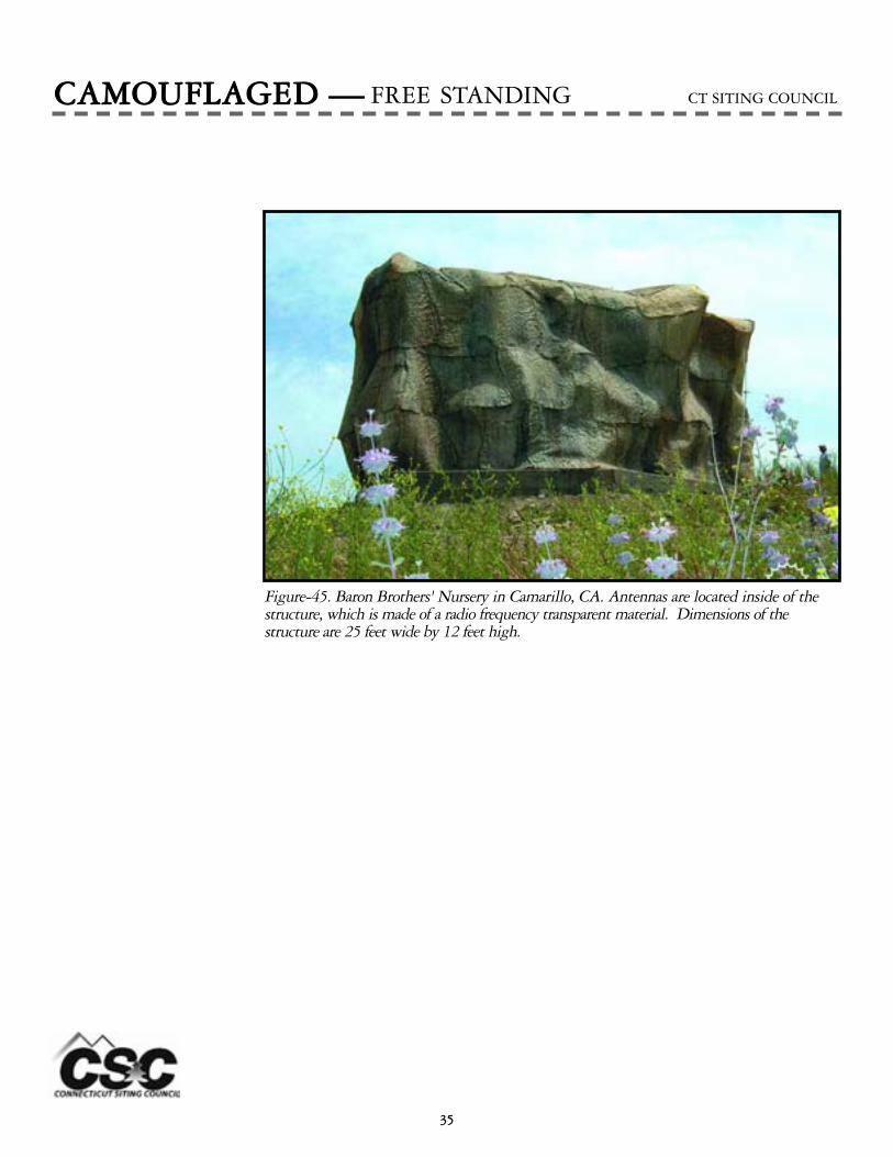
Figure-45. Baron Brothers' Nursery in Camarillo, CA. Antennas are located inside of thestructure, which is made of a radio frequency transparent material. Dimensions of the structure are 25 feet wide by 12 feet high.

3366
CCAAMMOOUUFFLLAAGGEEDD —— FREE STANDING CT SITING COUNCIL
Figure-47. Rocky Peak Church in Chattsworth, CA. Antennas are located inside of the structure, which is made of a radio frequency transparent material. Dimensions of the structure are 11 feet 6 inches tall by 8 feet in diameter.
Figure-46. Chico Hills and Bundy in Menifee, CA. Antennas are located inside of the struc-ture, which is made of a radio frequency transparent material. Dimensions of the structure are15 feet wide by 47 feet long by 17 feet high.

3377
Wireless telecommunicationantennas can be installed inor on buildings andcamouflaged to appear asthough they are part of the building.
CCAAMMOOUUFFLLAAGGEEDD —— ROOFTOP STRUCTURES CT SITING COUNCIL

3388
Figure-48. 5th Street in Derby, CT. Photograph taken in March of 2001.
CCAAMMOOUUFFLLAAGGEEDD —— ROOFTOP STRUCTURES CT SITING COUNCIL

3399
CCAAMMOOUUFFLLAAGGEEDD —— ROOFTOP STRUCTURES CT SITING COUNCIL
Figure-49. Shady Canyon Driving Range in Irvine, CA. The height of the structure is 21feet 2 inches. Antennas are located at 17 feet 2 inches agl.

4400
Figure-50. Elizabeth Street in Derby, CT. Photograph taken in March of 2001.
CCAAMMOOUUFFLLAAGGEEDD —— ROOFTOP STRUCTURES CT SITING COUNCIL

4411
CCAAMMOOUUFFLLAAGGEEDD —— ROOFTOP STRUCTURES CT SITING COUNCIL
Figure-51. Carpinteria Best Western in Carpinteria, CA.The structure extends to 56 feet 8 inches.
Figure-52. Cerritos Town Center inCerritos, CA. The structure is 68 feet6 inches tall. Antennas are located at61 feet 8 inches agl and 50 feet agl.

4422
CCAAMMOOUUFFLLAAGGEEDD —— ROOFTOP STRUCTURES CT SITING COUNCIL
Figure-53. Lantern Bay in Dana Point, CA. The height of the structure is 54 feet 11 inches. The antennas are located at 50 feet 11 inches agl.
Figure-54. Highway 101 and 12 in SantaRosa, CA. The structure is 61 feet 9 inches.Antennas are located at 59 feet agl.

4433
CCLLOOCCKK TTOOWWEERRSS
CCAAMMOOUUFFLLAAGGEEDD —— ROOFTOP STRUCTURES CT SITING COUNCIL
Figure-56. Gordon Square ShoppingCenter in Buena Park, CA. Thestructure is 51 feet tall. Antennas arelocated at 44 feet agl.
Figure-55. Ontario Convention Center inOntario, CA. Structure is 86 feet 10 inches.

4444
RREELLIIGGIIOOUUSSTTOOWWEERRSS
CCAAMMOOUUFFLLAAGGEEDD —— ROOFTOP STRUCTURES CT SITING COUNCIL
Figure-57. St. George Church Cross inUpland, CA. The structure is 35 feet tall. The top of the antennas extend to 34.5 feet agl.
Figure-58. First United Methodist Churchof Lakewood in Lakewood, CA. The structureis 56 feet 6 inches. Antennas are located at40 feet 6 inches agl.
Figure-59. Nexte Del Mar Heights in SanDiego, CA. Structure is 6 feet 8 inches fromthe top of the building.
Figure-60. Montfort Church in Santa Maria,CA. She structure is 50 feet tall. Antennas arelocated at 50 feet and 42 feet agl.

4455
RREELLIIGGIIOOUUSSTTOOWWEERRSS
CCAAMMOOUUFFLLAAGGEEDD —— ROOFTOP STRUCTURES CT SITING COUNCIL
Figure-61. Peralta Park in Oakland,CA. The antennas are located at 54 feet 2inches agl.
Figure-63. Rosemont in Sacramento, CA.The structure is 69 feet 9 inches. The anten-nas are located between 42 feet and 60 feetand between 26 feet and 38 feet agl.
Figure-62. San Ramon-Montevideo in SanRamon, CA.

4466
Figure-64. 17 West Rocks Road Norwalk, CT. Photograph taken in April of 2004.
Fencing and landscaping areoften used to screen thecompound of a wirelesstelecommunications site.
LLAANNDDSSCCAAPPIINNGG && FFEENNCCIINNGG CT SITING COUNCIL

4477
Figure-65. 300 Governor's Highway in South Windsor, CT. Photograph taken in May of 2004.
LLAANNDDSSCCAAPPIINNGG && FFEENNCCIINNGG CT SITING COUNCIL

4488
Figure-66. 1725 Stafford Road in Mansfield, CT. Photograph taken in June of 2004.
LLAANNDDSSCCAAPPIINNGG && FFEENNCCIINNGG CT SITING COUNCIL

4499
Figure-67. 281 Woodhouse Road in Fairfield, CT. Photograph taken in June of 2000.
LLAANNDDSSCCAAPPIINNGG && FFEENNCCIINNGG CT SITING COUNCIL

5500
TTOOWWEERRSS —— ANTENNAS AND MOUNTING TYPES CT SITING COUNCIL
Antennas can be installedwithin, flush mounted to,or installed on a platformon a monopole. A regularantenna platform is shapedas a triangle with antennasmounted on each side ofthe triangle. A low-profileantenna platform is thesame as a regular antennaplatform; however themetal sides of the triangleare thinner and thereforeless visible. A t-bar antennaplatform consists of threearms extending from themonopole facing differentdirections with antennasmounted straight across theother end of the arm.
Figure-68. Two examples of antenna mounting types on a monopole. The top drawing is anexample of a low-profile antenna mount. The bottom drawing is an example of a t-armantenna mount.

5511
Figure-69. 393 Jackson Hill Road, Middlefield, CT. Photograph taken in April of 2003.
TTOOWWEERRSS —— ANTENNAS AND MOUNTING TYPES CT SITING COUNCIL
Full Platform
Low ProfileAntenna

5522
Figure-70. 627 Honey Spot Road, Stratford, CT. Photograph taken in November of 2004.
TTOOWWEERRSS —— ANTENNAS AND MOUNTING TYPES CT SITING COUNCIL
Full Platform
Full Platform
External Flush Mount
External Flush Mount

5533
Figure-71. 78 Route 81 Killingsworth, CT. Photograph taken in December of 2004.
TTOOWWEERRSS —— ANTENNAS AND MOUNTING TYPES CT SITING COUNCIL
Full Platform
T-bar

5544
Figure-72. 2 Prestigue park Road, East Hartford, CT. Photograph taken in March of 2004.
TTOOWWEERRSS —— ANTENNAS AND MOUNTING TYPES CT SITING COUNCIL
Full Platform
T-bar
Whip Antenna

5555
PPIICCTTUURREEDD::
1. The stub for a guyedtower
2. Setting the stub
3. Hoisting the "gin pole"(used as a pulley attachedto the side of the tower tohaul additional sections,equipment and antennaeup to the crew)
4. Hoisting a tower section,
5. A tower section isbrought up the gin polethen finally bolted to thesection preceding it.
4 5
TTOOWWEERRSS —— CONSTRUCTION CT SITING COUNCIL
32
1

5566
Whip Antenna
TTOOWWEERRSS —— DIAGRAM CT SITING COUNCIL
Microwave Dish
Yagi Antenna
Coaxle Cable
Equipment Shelter

5577
Sections
Anchors for Guy Wires
Guy Wire
Cross-Sections
TTOOWWEERRSS —— ANATOMY CT SITING COUNCIL

5588
AABBSSOORRPPTTIIOONN:: The reduction of signal strength by the presence of foliage.
AABBOOVVEE GGRROOUUNNDD LLEEVVEELL:: (AGL) Height above ground level of a structure.
AABBOOVVEE MMEEAANN SSEEAA LLEEVVEELL:: (AMSL) referring to the height of the ground compared with sea level.
AACCCCEESSSS EEAASSEEMMEENNTT:: The right to cross over land to reach the parcel upon which a tower is located.
AAMMEERRIICCAANN NNAATTIIOONNAALL
SSTTAANNDDAARRDDSS IINNSSTTIITTUUTTEE:: (ANSI) which creates standards for design and operation of telecommunications facilities.
AANNAALLOOGG:: The original method of modifying radio signals to enable them to carry information.
AANNCCHHOORRSS:: Hardware set in ground to hold guy wires.
AANNTTEENNNNAA:: A device that is used to transmit and receive radio frequency signals.
AANNTTEENNNNAA FFAARRMM:: A term referring to a site with multiple towers in close proximity.
BBAASSEE SSTTAATTIIOONN:: "A central radio transmitter/receiver that communicates with mobile telephones within agiven range."
BBLLOOCCKKAAGGEE:: The prevention of a radio signal path due to an object or terrain.
BBRROOAADDBBAANNDD:: A transmitter that has a sufficient bandwidth to carry multiple voice, video or datachannels simultaneously.
CCAARRRRIIEERR:: A service provider or operator that provides customers with service for their wireless phones.
CCEELLLL:: A central transmission/reception point of an interconnected, 2-way radio system employing frequency hand off. Or a geographic unit of coverage.
CCEELLLL SSIITTEE:: "The location where a wireless antenna and network communications equipment isplaced in order to provide wireless service in a geographic area.
CCEELLLL SSPPLLIITTTTIINNGG:: A method to increase the capacity of a wireless system by dividing one celll into two ormore smaller cells.
CCOOAAXX:: Cable used for connecting transmitters and antennas which can add to the wind load on atower.
CCOODDEE DDIIVVIISSIIOONN
MMUULLTTIIPPLLEE AACCCCEESSSS:: (CDMA) "A technology used to transmit wireless calls by assigning them codes.
CCOO--LLOOCCAATTIIOONN:: The placement of more than one carrier’s equipment upon a single site.
CCOOOORRDDIINNAATTEESS:: Referring to geographic coordinates (N. Latitude and W. Longitude).
CCEELLLLUULLAARR SSIITTEE OONN
WWHHEEEELLSS:: (COW) resembling a truck trailer.
GGLLOOSSSSAARRYY CT SITING COUNCIL

5599
DDIIRREECCTTIIOONNAALL:: A type of antenna that places a signal toward a particular direction.
DDIIGGIITTAALL: The method that converts signals into binary digits. Digital technology has largelyreplaced analog technology.
DDIISSHH:: A microwave dish for transmission or reception, usually varying in size from one to three meters
DDOOWWNN TTIILLTT:: A type of antenna that aims the signal down from the tower, rather than toward thehorizon.
DDUUAALL BBAANNDD:: "A wireless handset that works on more than one spectrum frequency."
DDUUAALL MMOODDEE:: "A wireless handset that works on analog and digital networks."
EENNCCLLOOSSUURREE:: A shelter for housing telecommunications equipment.
FFAACCEE((SS)):: The side(s) of a tower, usually three or four.
FFEEDDEERRAALL AAVVIIAATTIIOONN
AADDMMIINNIISSTTRRAATTIIOONN:: (FAA) government office that regulates the location and height of towers
FFEEDDEERRAALL CCOOMMMMUUNNIICCAATTIIOONNSS
CCOOMMMMIISSSSIIOONN:: (FCC) government office that regulates the use of radio facilities.
GGAAIINN:: The increase in wattage on a radio signal usually created via antenna design.
GGLLOOBBAALL PPOOSSIITTIIOONNIINNGG
SSYYSSTTEEMM:: The use of satellite-based system and receiver to determine exact location on earth.
GGUUYY WWIIRREESS:: Steel cable extending from positions on the tower to the ground to support the structure.
GGUUYYEEDD TTOOWWEERR:: A tower which is supported by the use of guy wires.
HHAANNDDOOFFFF:: The process by which a wireless network automatically switches a mobile call to an adjacent cell site.
LLAATTTTIICCEE:: A style of tower employing multiple, intercrossing steel supports.
LLIIGGHHTTIINNGG:: General reference to strobe lighting of a tower to alert night aviation traffic.
LLIIGGHHTTNNIINNGG AARRRREESSTTEERR:: A device for guiding lightning strikes to ground for use on towers.
LLIINNEE OOFF SSIIGGHHTT:: Ability to receive a signal without blockage or shadowing due to the location oftransmitter and receiver.
LLOOSSSS:: The loss in wattage on a radio signal usually caused by the length and girth of the coax cable
MMAASSTTEERR AANNTTEENNNNAA:: An antenna shared by more than one operator.
MMEEGGAAHHEERRTTZZ:: (MHz) A unit of frequency that is equal to one million hertz (cycles) per second.
GGLLOOSSSSAARRYY CT SITING COUNCIL

6600
MMOONNOOPPOOLLEE:: A free standing tower in the shape of a pole.
MMOOUUNNTTIINNGG:: The placement of hardware, including antennas, on a structure
NNAADD 2277:: A method for calculating geographic coordinates created in 1927
NNAADD 8833:: A method for calculating geographic coordinates, revising NAD 27, and created in 1983.
OOMMNNIIDDIIRREECCTTIIOONNAALL:: A type of antenna that produces a signal in a 360 degree pattern.
OORRIIEENNTTAATTIIOONN:: Positioning of the legs of a tower in relation to true north.
PPAADD:: Concrete pad for construction of towers or enclosures.
PPAAIINNTTIINNGG:: General reference to stripe marking on a tower to alert aviation traffic.
PPAANNEELL AANNTTEENNNNAA:: An antenna shaped like a panel normally employed for cell operations
PPAATTHH:: Course of a radio signal between points
PPAATTHH LLOOSSSS:: Amount of power lost in a radio signal as it moves through the air.
PPEERRSSOONNAALL
CCOOMMMMUUNNIICCAATTIIOONNSS
SSEERRVVIICCEESS:: (PCS) licensed in the 1900 MHz band.
PPRROOPPAAGGAATTIIOONN:: The quality of a signal for the purpose of being usable across a given geographic area.
RRAADDIIOO LLIICCEENNSSEE:: Authority granted by FCC to operate a radio facility.
RREEFFLLEECCTTIIOONN:: The bouncing of a radio signal off an object.
RREEPPEEAATTEERR:: A transceiver used to "repeat" incoming signals and retransmit them in a different direction to increase range of coverage.
RRAADDIIOO FFRREEQQUUEENNCCYY:: (RF) employed as a general term referring to any use of the radio spectrum.
RRFF EEXXPPOOSSUURREE:: Refers to the potential hazard from human exposure to RF radiation.
RRFF DDEESSIIGGNN:: A general term for the design of a radio system.
RROOAAMMIINNGG:: A process used when traveling outside of a carrier’s local service area. Users can makeand receive calls through operation on another carrier’s service coverage area.
RROOOOFFTTOOPP SSIITTEE:: An antenna mounted on the roof of a building, with the transmitter housed within the building.
SSEELLFF SSUUPPPPOORRTTIINNGG
LLAATTTTIICCEE:: A tower which relies on footings for support, rather than guy wires.
SSHHAADDOOWWIINNGG:: The reduction of a radio signal path due to an object or terrain.
SSHHEELLTTEERR:: An enclosure for housing telecommunications equipment.
GGLLOOSSSSAARRYY CT SITING COUNCIL

6611
SSIIDDEE MMOOUUNNTTEEDD:: Any position for an antenna that is not at the top.
SSIITTEE AACCQQUUIISSIITTIIOONN:: The act of identifying and/or securing the use of a site for a carrier.
SSTTRRUUCCTTUURRAALL IINNTTEEGGRRIITTYY:: General strength of a tower under present conditions, related to wind load.
TTIIMMEE DDIIVVIISSIIOONN
MMUULLTTIIPPLLEE AACCCCEESSSS:: (TDMA) A technology that allows the transmission of information by dividing calls intotime slots that last approximately a fraction of a second.
UUPPLLIINNKK:: A radio path going up toward a satellite.
UUTTIILLIITTYY AACCCCEESSSS:: The right to run electricity and telephone lines across a parcel of land.
WWHHIIPP AANNTTEENNNNAA:: An antenna that is a single pole.
WWIINNDD LLOOAADD:: The amount of weight (at given positions) that the tower can withstand under wind conditions.
WWIIRREELLEESSSS:: A general term referring to use of radio over air.
YYAAGGII:: A type of directional antenna similar to a UHF television reception antenna.
GGLLOOSSSSAARRYY CT SITING COUNCIL

PPAAGGEE 11:: Figure-1.168 Catoona Lane in Stamford, CT. Photograph taken in October of
PPAAGGEE 22:: Figure-2. Route 80 in Killingworth, CT. Photograph taken in November of 2004.
PPAAGGEE 33:: Figure-3. 11 Willard Road in Norwalk, CT. Photograph taken in April of 2004.
PPAAGGEE 44:: Figure-4. Mohawk Mountain in Cornwall, CT. Photograph taken in December of 2001.
PPAAGGEE 55:: Figure-5. 528 Wheelers Farms Road in Milford, CT. Photograph taken in January of
PPAAGGEE 66:: Figure-6. 78 Route 81 in Killingworth, CT. Photograph taken in December of 2003.
PPAAGGEE 77:: Figure-7. 99 Briar Hill Road in Groton, CT. Photograph taken in April of 2004.
PPAAGGEE 88:: Figure-8. Tolland Avenue in Stafford Springs, CT. Photograph taken in February of 2004.
PPAAGGEE 99:: Figure-9. A passive microwave reflector is located at 652 Glenbrook Road in Stamford, CT.Photograph taken in December of 2006.
PPAAGGEE 1100:: Figure-10. Buckingham Street in Watertown, CT. Photograph taken in December of 2001.
PPAAGGEE 1111:: Figure-11. Wireless telecommunications antennas attached to a billboard located at 521 SouthLeonard Street in Waterbury. Photograph taken in October of 2006.
PPAAGGEE 1122:: Figure-12. Antennas attached to a smokestack located at 500 South Broad Street in Meriden.Photograph taken in October of 2006
PPAAGGEE 1133:: Figure-13. Co-location on an extended electric transmission pole on Bartholomew Road inMiddletown, CT. Photograph taken in June of 2004.
PPAAGGEE 1144:: Figure-14. Co-location on an electric transmission structure located on 3 Mechanic Street inDarien, CT. Photograph taken in November of 2001.
PPAAGGEE 1155:: Figure-15. Park lights share a structure with wireless telecommunications antennas at ChelseyPark in New Britain, CT. Photograph taken in September of 2006.
PPAAGGEE 1166:: Figure-16. 265 Benham Street in Hamden, CT. Photograph taken in February of 2004.
IINNDDEEXX CT SITING COUNCIL
6622
IINNDDEEXX CT SITING COUNCIL
6633
PPAAGGEE 1177:: Figure-17. A ballast frame rooftop mounted antenna is located on Winter Street in NewBritain, CT. Photograph taken in December of 2006.
PPAAGGEE 1188:: Figure-18. 151 Sand Hill Road in Windsor, CT. Photograph taken in September of 2006.Figure-19. 23 Kelleher Court in Wethersfield, CT. Photograph taken in September of 2006.
PPAAGGEE 1199:: Figure-20. 1320 Chopsey Hill Road in Bridgeport, CT. Photograph taken in October of 2006.
PPAAGGEE 2200:: Figure-21. 1445 Forbes Avenue in East Hartford, CT. Photograph taken December of 2000.Figure-22. 1320 Chopsey Hill Road in Bridgeport, CT. Photograph taken in October of 2006.
PPAAGGEE 2211:: Figure-23. A 120-foot telecommunications facility, disguised as a tree, located at 477 Route 7in Sharon, CT. Photographed in January of 2007.
PPAAGGEE 2222:: Figure-24. A 110-foot telecommunications facility disguised as a tree located at 70 Herb Roadin Sharon, CT. Photographed in February of 2007.
PPAAGGEE 2233:: Figure-25. A 125-foot telecommunications facility disguised as a bell tower located at theHarvest Baptist Church at 1440 Litchfield Turnpike in New Hartford, CT. Photographed inFebruary of 2007.
PPAAGGEE 2244:: Figure-26. An 80-foot wood laminate pole located at 41 Padanaram Road in Danbury, CT.Photographed in May of 2006.
PPAAGGEE 2255:: Figure-27. A 55-foot wooden pole located at 111 Middle Turnpike in Mansfield, CT (alsoknown as a “brown stick”). Photographed in October of 2004.
PPAAGGEE 2266:: Figure-28. 127 New Hartford Road in Barkhamsted, CT. Photograph taken in January of 2004.
PPAAGGEE 2277:: Figure-29. Near Interstate 405 and Long Beach Boulevard in Long Beach, CA.
PPAAGGEE 2288:: Figure-30. Pacifica Mormandie in Torrance, CA. The structure is 62 feet tall. Antennas arelocated at 55 feet agl.
Figure-31. Pacifica Mormandie in Torrance, CA. The structure is 62 feet tall. Antennas arelocated at 55 feet agl.

IINNDDEEXX CT SITING COUNCIL
6644
PPAAGGEE 2299:: Figure-32. 100 Pond Lily Avenue in New Haven, CT. Antennas are located within the flag-pole structure and equipment is housed within a brick façade that matches the building.Photograph taken in June of 2006.
Figure-33. 985 Farmington Avenue in Bristol, CT. Antennas are located within the flagpolestructure and equipment is at the base of the structure.
PPAAGGEE 3300:: Figure-34. Vista, CA. The structure is 45 feet tall. Antennas are located at 41.5 feet agl and35 feet agl.
PPAAGGEE 3311:: Figure-35. 890 Evergreen Avenue in Hamden, CT. Photograph taken in July of 2001.
PPAAGGEE 3322:: Figure-36. Betteravia Properties in Santa Maria, CA. The structure is 50 feet tall. Antennasare located at 48 feet agl.
Figure-37. Lamb of God in Anaheim, CA. The structure is 60 feet tall.
Figure-38. City of Lynwood, CA. Dimensions of the structure are 60 feet tall by 8 feet wide.
PPAAGGEE 3333:: Figure-39. Magnolia Park in Upland, CA. The structure is 60 feet tall.
Figure-40. Mason in Irvine, CA. The structure is 60 feet tall.
Figure-41. Promenade in Corona, CA. The structure is 40 feet tall.
PPAAGGEE 3344:: Figure-42. Cajon Pass in Oak Hills, CA. The structure is 90 feet tall. Antennas are withinthe water tank structure at 80 feet 8 inches agl and 70 feet agl.
Figure-43. Via Verde in San Dimas, CA. The structure is 60 feet tall. Antennas are mountedwithin the water tank at 58 feet agl and 47 feet agl.
Figure-44. Highway 38 Wabash in Mentone, CA. The structure is 60 feet tall. Antennas arelocated at 56 feet agl and 48.5 feet agl.
PPAAGGEE 3355:: Figure-45. Baron Brothers' Nursery in Camarillo, CA. Antennas are located inside of thestructure, which is made of a radio frequency transparent material. Dimensions of the structureare 25 feet wide by 12 feet high.

IINNDDEEXX CT SITING COUNCIL
6655
PPAAGGEE 3366:: Figure-46. Chico Hills and Bundy in Menifee, CA. Antennas are located inside of thestructure, which is made of a radio frequency transparent material. Dimensions of the structureare 15 feet wide by 47 feet long by 17 feet high.
Figure-47. Rocky Peak Church in Chattsworth, CA. Antennas are located inside of the struc-ture, which is made of a radio frequency transparent material. Dimensions of the structure are11 feet 6 inches tall by 8 feet in diameter.
PPAAGGEE 3377:: NNAA
PPAAGGEE 3388:: Figure-48. 5th Street in Derby, CT. Photograph taken in March of 2001.
PPAAGGEE 3399:: Figure-49. Shady Canyon Driving Range in Irvine, CA. The height of the structure is 21 feet2 inches. Antennas are located at 17 feet 2 inches agl.
PPAAGGEE 4400:: Figure-50. Elizabeth Street in Derby, CT. Photograph taken in March of 2001.
PPAAGGEE 4411:: Figure-51. Carpinteria Best Western in Carpinteria, CA. The structure extends to 56 feet 8inches.
Figure-52. Cerritos Town Center in Cerritos, CA. The structure is 68 feet 6 inches tall.Antennas are located at 61 feet 8 inches agl and 50 feet agl.
PPAAGGEE 4422:: Figure-53. Lantern Bay in Dana Point, CA. The height of the structure is 54 feet 11 inches.The antennas are located at 50 feet 11 inches agl.
Figure-54. Highway 101 and 12 in Santa Rosa, CA. The structure is 61 feet 9 inches.Antennas are located at 59 feet agl.
PPAAGGEE 4433:: Figure-55. Ontario Convention Center in Ontario, CA. Structure is 86 feet 10 inches.
Figure-56. Gordon Square Shopping Center in Buena Park, CA. The structure is 51 feet tall.Antennas are located at 44 feet agl.

IINNDDEEXX CT SITING COUNCIL
6666
PPAAGGEE 4444:: Figure-57. St. George Church Cross in Upland, CA. The structure is 35 feet tall. The top of the antennas extend to 34.5 feet agl.
Figure-58. First United Methodist Church of Lakewood in Lakewood, CA. The structure is 56feet 6 inches. Antennas are located at 40 feet 6 inches agl.
Figure-59. Nexte Del Mar Heights in San Diego, CA. Structure is 6 feet 8 inches from the topof the building.
Figure-60. Montfort Church in Santa Maria, CA. She structure is 50 feet tall. Antennas arelocated at 50 feet and 42 feet agl.
PPAAGGEE 4455:: Figure-61. Peralta Park in Oakland, CA. The antennas are located at 54 feet 2 inches agl.
Figure-62. San Ramon-Montevideo in San Ramon, CA.
Figure-63. Rosemont in Sacramento, CA. The structure is 69 feet 9 inches. The antennas arelocated between 42 feet and 60 feet and between 26 feet and 38 feet agl.
PPAAGGEE 4466:: Figure-64. 17 West Rocks Road Norwalk, CT. Photograph taken in April of 2004.
PPAAGGEE 4477:: Figure-65. 300 Governor's Highway in South Windsor, CT. Photograph taken in May of 2004.
PPAAGGEE 4488:: Figure-66. 1725 Stafford Road in Mansfield, CT. Photograph taken in June of 2004.
PPAAGGEE 4499:: Figure-67. 281 Woodhouse Road in Fairfield, CT. Photograph taken in June of 2000.
PPAAGGEE 5500:: Figure-68. Mounting Illustrations
PPAAGGEE 5511:: Figure-69. 393 Jackson Hill Road, Middlefield, CT. Photograph taken in April of 2003.
PPAAGGEE 5522:: Figure-70. 627 Honey Spot Road, Stratford, CT. Photograph taken in November of 2004.
PPAAGGEE 5533:: Figure-71. 78 Route 81 Killingsworth, CT. Photograph taken in December of 2004.
PPAAGGEE 5544:: Figure-72. 2 Prestigue park Road, East Hartford, CT. Photograph taken in March of 2004.