Embed Size (px)
Citation preview

Telecommunication Switching
Kamalasanan.p.k

Switching functions
Major component of a switching system is the set of input and output circuits.,,
Primary function of a switching system is to establish a temporary electrical path between a given inlet-outlet pair called switching matrix or switching network.

Electronic SPC Exchanges
• Telecommunication is concerned with transmission of messages between two distinct points.
• Telephone exchange is a system of electronic components that connects telephone calls..
Switching system fundamentals
• Telecommunication switching systems perform three basic functions:
1) They transmit signals to convey the identity of the called address and alert the called station
2) Establish connection through a switching network for conversational use during the entire call
3) Supervision

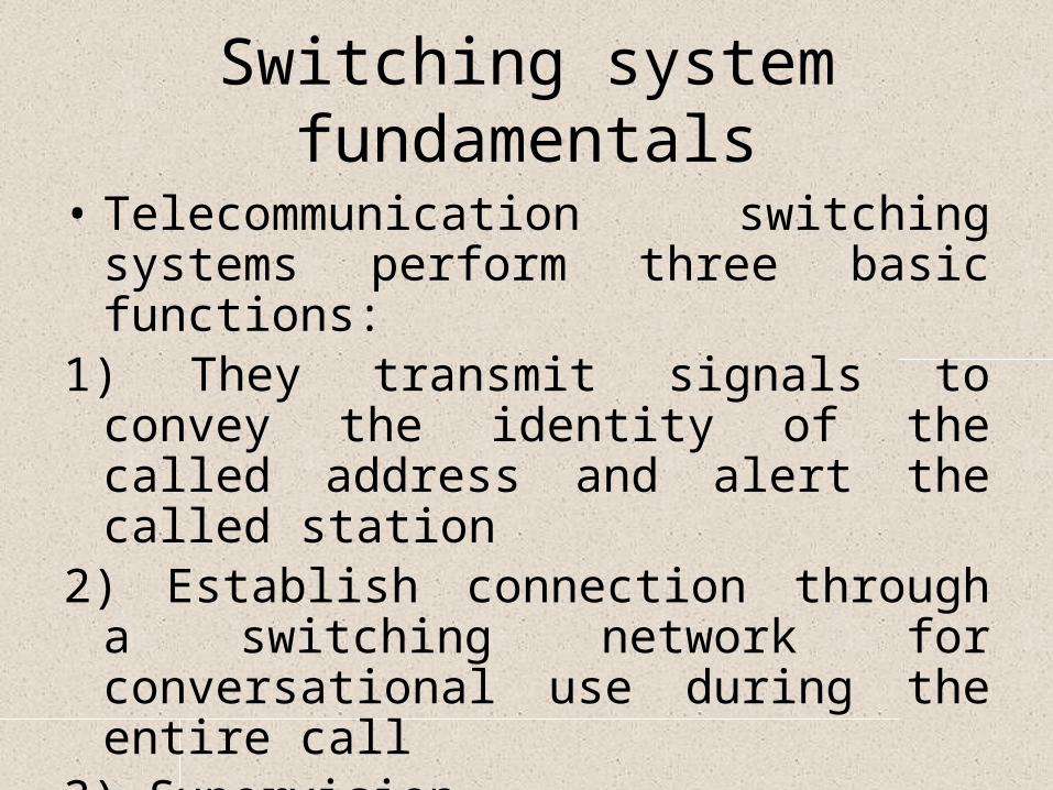
SPC Exchange Functional Blocks
• Terminal Equipment• Switching Network• Switching Peripherals• 1.Scanner• 2.Marker• 3.Distributor• Signaling• Central Control• Man machine dialogue terminals

Terminal Equipment
• Types of interfaces
• Subscriber Interfaces – Can be analog subscriber and Digital subscriber interface.
• Trunk Interface- For putting through calls from one exchange to another, digital trunks are required.
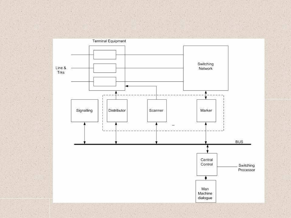
SPC Exchanges• Terminal Equipment All the subscriber line, inter exchange trunk and service circuits are terminated.
Analog to Digital Conversion….
BORSHT functionsB-Battery feedO-Overload ProtectionR-RingingS-Supervision of loop statusH-HybridT-Connection to test equipments

Switching Network
• One of the largest sub-system in terms of size of an exchange
• Main functions are• 1.Switching: Setting up a temperory
connection between two or more terminations
• 2.Transmission of speech and signals between these terminations with reliable accuracy

Switching Network
• Two types of switching systems• 1.Time Division Switching• 2.Space Division Switching• Usually a combination of both is used• T-S-T structure is generally used• The basic principle behind the switching
system is PCM(Pulse Code Modulation).So its also known as Digital Switching

PCMSampling freq= 8KHz,No of bits =8
channel bitrate=64KbpsTotal bit rate=32x64=2048Kbps
Time period for sampling=1/8000=125 microsecondTime available per channel=125/32=3.9 microsec
Time available for each bit=3.9/8=0.488 microsec(488ns)
Time Division Switching
• In TDS, a number of calls share the same path on time division sharing basis
• The path is shared sequentially for a fraction of a time by different calls. This process is repeated periodically at suitably high rate (8 Khz).ie every 125 micro seconds.
• These samples are time multiplexed with staggered samples of other speech channels to enable sharing of same path by many calls.
Time Switch
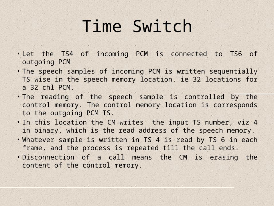
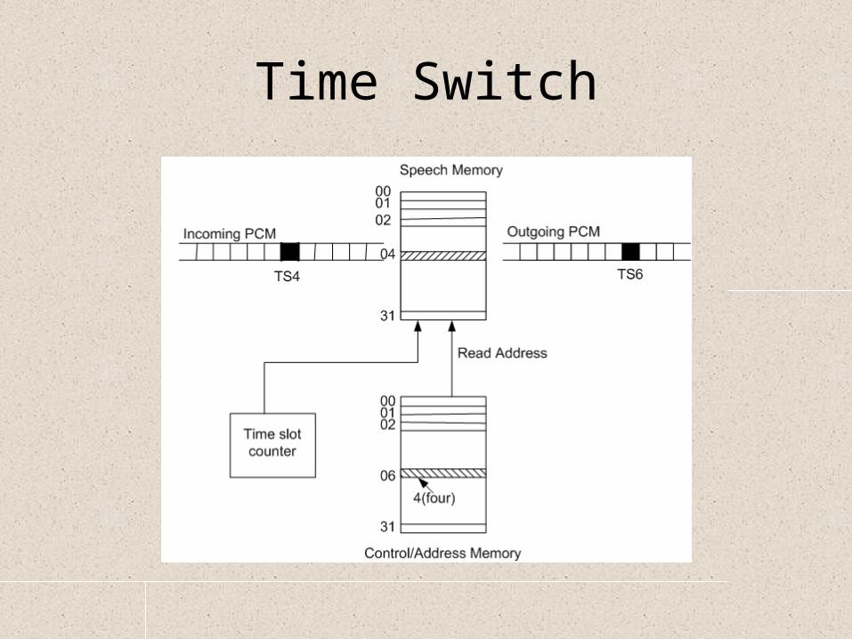
Time Switch• Let the TS4 of incoming PCM is connected to TS6 of outgoing PCM• The speech samples of incoming PCM is written sequentially TS wise
in the speech memory location. ie 32 locations for a 32 chl PCM.• The reading of the speech sample is controlled by the control
memory. The control memory location is corresponds to the outgoing PCM TS.
• In this location the CM writes the input TS number, viz 4 in binary, which is the read address of the speech memory.
• Whatever sample is written in TS 4 is read by TS 6 in each frame, and the process is repeated till the call ends.
• Disconnection of a call means the CM is erasing the content of the control memory.

Time Switching
1
2
3
22
23
24
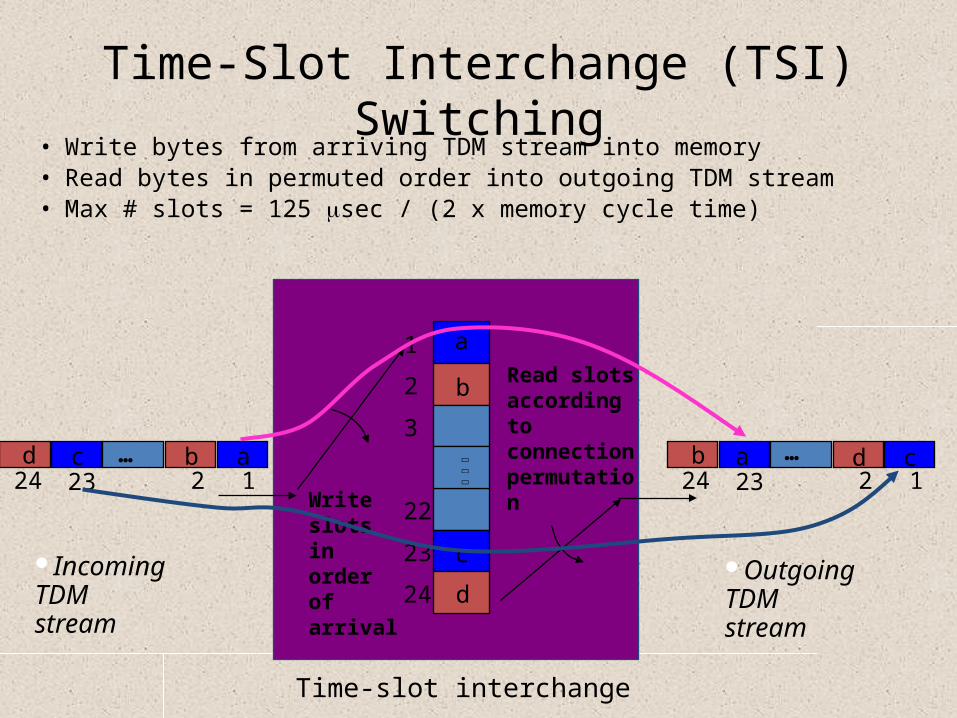
Write slots in order of arrival
Read slots according to connection permutation
24 23 12
Time-slot interchange
24 23 12abcd b a d c
a
b
c
d
… …
Time-Slot Interchange (TSI) Switching• Write bytes from arriving TDM stream into memory• Read bytes in permuted order into outgoing TDM stream• Max # slots = 125 msec / (2 x memory cycle time)
Incoming TDM stream
Outgoing TDM stream
#17
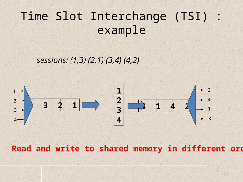
Time Slot Interchange (TSI) : example
sessions: (1,3) (2,1) (3,4) (4,2)
4 3 2 1 3 1 4 2
1234
Read and write to shared memory in different order
1
2
3
4
2
4
1
3


Timeslot interchange
Space Switching
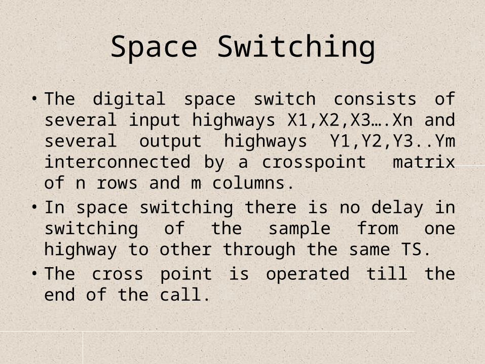
• The digital space switch consists of several input highways X1,X2,X3….Xn and several output highways Y1,Y2,Y3..Ym interconnected by a crosspoint matrix of n rows and m columns.
• In space switching there is no delay in switching of the sample from one highway to other through the same TS.
• The cross point is operated till the end of the call.

Space Switch

Space Switch
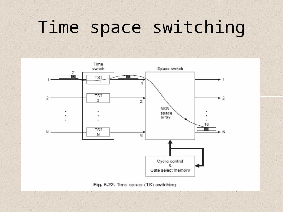
Time space switching

TST SWITCH

T-S-T Network
Switching Peripherals
• SCANNER• Its purpose is to detect and inform the central
computer about all significant events/signals on subscriber lines and trunks connected to the exchange.
• To detect new calls, while complying with the dial tone connection specifications ,each line must be scanned about every 300 milliseconds
Switching Peripherals
• MARKER• Marker performs physical setup and release of
path through the switching network under the control of CC.
• Depending upon whether switching is Time division or Space division,marker either writes information in the control memory of time and space stages or physically operates the cross points (Space division switching).
Switching Peripherals
• DISTRIBUTOR• It is a buffer between high-speed low-power
Central Control and relatively slow-speed high-power signaling terminal circuits
• Interface between subscriber line circuits/ trunks and CC for distributing various signals and tones on subscriber lines and junctions.

SIGNALING
Signaling
Telecommunication network establishes and releases temporary connections in accordance with the instructions and information from subscriber lines and inter exchange trunks in form of various signals.
Signalling is happening 1.Between subscriber lines and Exchange2.Between two exchanges (inter exchange
signalling)
Signaling
• A signaling system uses a language which enables two equipments to converse for the purpose of setting up calls.
• Like any other language it possesses a ‘vocabulary’ of varying size and varying precision.
• It has a syntax in the form of a complex set of rules.

Signaling Techniques
• 1.Subscriber signaling• 2.Inter exchange signaling• Signaling informations exchanged between
Subscriber and exchange is Subscriber signaling.• Call request and Address signals are examples.• When subscriber lifts the handset, increases the
line current, and exchange detect it as a call request and feed dial tone.

Register Signaling
• Address Signals• 1.Decadic dialing 2.DTMF dialing• The address digits may be transmitted as a
sequence of interruption of the DC loop by a rotary dial or decadic push button keypad. The number of breaks indicate a digit. The rate of interruptions is 10 per second and the make/break ratio is 1:2. There has to be an inter digital pause of few hundred milliseconds to distinguish between two consecutive digits.
Decadic Dialling
• The Number of pulses in a train equal to the digit value.
• The inter digital pause is at least 200msec.• The pulse rate is usually 20 pulses per sec• Rotary telephones are used• Break and make period is 66 2/3 and 33 1/3• Slow signaling
35
Dial Pulse
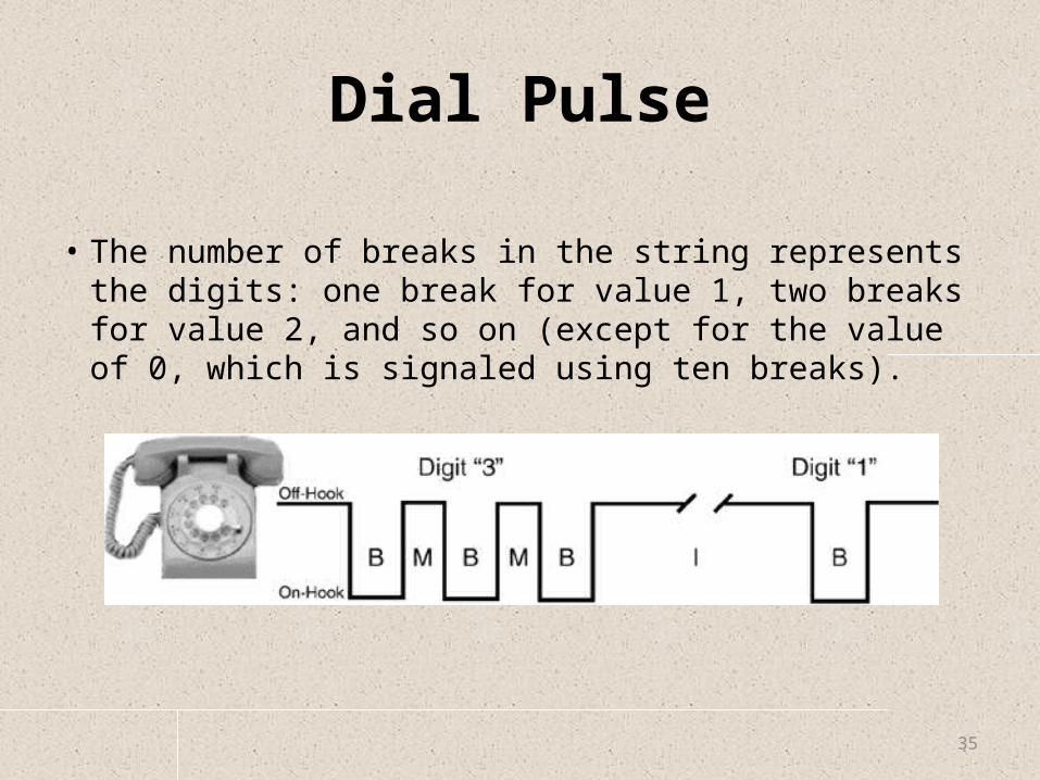
• The number of breaks in the string represents the digits: one break for value 1, two breaks for value 2, and so on (except for the value of 0, which is signaled using ten breaks).
DTMF
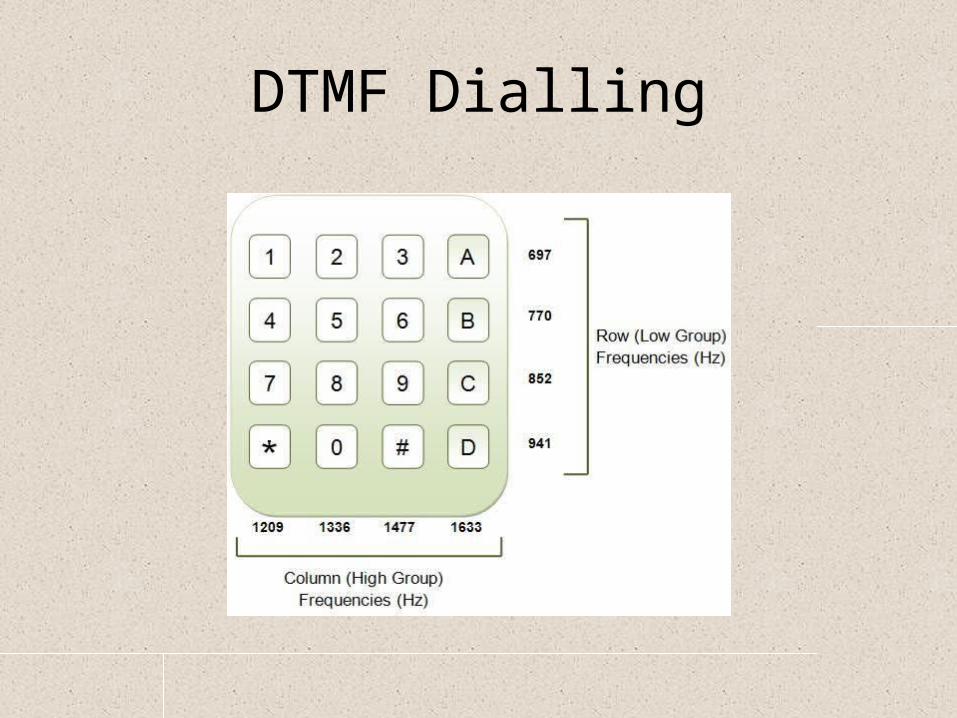
• Overcomes the constraints of decadic dialling• Pressing a key generates a signal comprising of
two frequencies ,one from each group. Hence called Dual Tone Multi Frequency.
• By this method dialling time is reduced as 10 digits per second.
• Since the frequencies lie in speech band, information can be sent in speech phase also and can be used for variety applications.
DTMF Dialling

Inter Exchange Signaling
• Link-by-link basis• End-to-end basis
• Link-by-link basis: Here the information is exchanged only between adjacent Registers.
Considering a three exchange A-B-C connection, initially the signaling is between A-B and then between B-C.

Link-by-link basis Signaling

End-To-End Signaling
• Here the originating Exchange controls the setting up of a call until it reaches the final destination.
• In a three exchange configuration A-B-C, Initially the signaling is between A-B and then between A-C ,after the B-C connection is established.

End-To-End basis Signaling
Signaling Techniques
• In band signaling• Out-of-band signaling
– - CCS signaling• E&M signaling• MF signaling

In - Band Signaling• Signaling path = voice path• Inband freq is 2600 Hz or 2400 Hz• Voice path clogged with signaling• Busy calls, congestion, and “ring-no-answers”
result in 20-35% of incomplete calls• Slower call setup due to channel sharing

Out Band Signaling
• Frequency is 3825Hz• Voice path clogging problem is solved• As the processing of signaling and speech
information is different,it is necessary to separate the two before feeding to the interface.
• Add up hardware costs

Digital signaling
• Channel Associated SignalingThe signaling can be transmitted over a channel
directly associated with the speech channelIn the PCM system,the signaling information is
conveyed on a separate channel which is rigidly associated with the speech channel.
• Common channel signalingA dedicated channel used for signaling
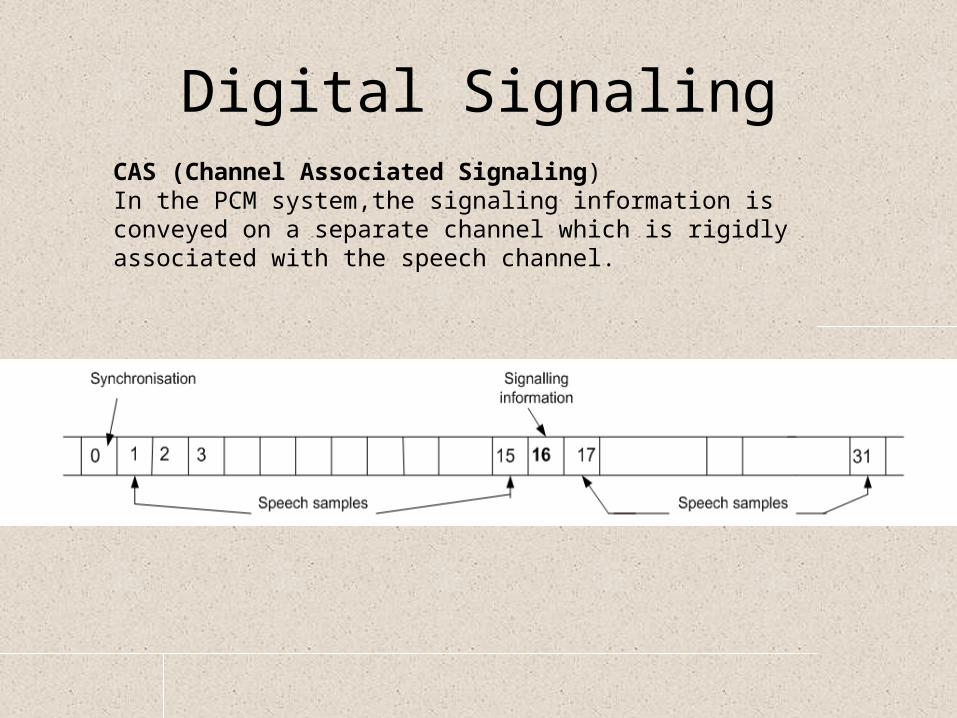
Digital SignalingCAS (Channel Associated Signaling)In the PCM system,the signaling information is conveyed on a separate channel which is rigidly associated with the speech channel.

CAS
• TS16 of each frame of 125 micro secs, is used to carry signals of 2 speech channels,each using 4 bits and both line signals and address information are conveyed by this method
• Hence for 30 chl PCM system 15 frames are required to carry all the signals
• Speech sampling frequency 8000Hz• Signal sampling frequency 500 Hz
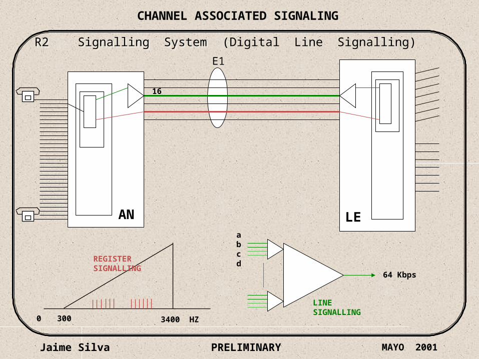
CHANNEL ASSOCIATED SIGNALING
Jaime Silva MAYO 2001PRELIMINARY
AN LE
E1
R2 Signalling System R2 Signalling System
300 3400 HZ0
LINESIGNALLING
REGISTERSIGNALLING
(Digital Line Signalling)
16
abcd
64 Kbps

Jaime Silva AUGUST 2000PRELIMINARY
0 1 2 15 16 17 29 30 31TimeSlots
Encoded speech signalsor data signals 1 to 15
Encoded speech signalsor data signals 16 to 30
LINE SignallingInformation
125 uSec256 bits
8 bits ( 3,9 uSec. )1 bit = 0,49 uSec.
ONE PCM ( E1 ) FRAMEONE PCM ( E1 ) FRAME
CHANNEL ASSOCIATED SIGNALING

Jaime Silva PRELIMINARY
FRAME 0 FRAME 1 FRAME 15
0 0
CAS Signalling in a2 Mbit/s System (2/2)
CAS Signalling in a2 Mbit/s System (2/2)
Signalling Frame
a b c d a b c d 0 0 0 0 X Y X X a b c d a b c d
MultiframeAlignmentSignal
Not multifr.AlignmentSignal
Signalling Words Signalling Words
Channel Channel 1 17
Channel Channel 15 31
a b c d = 1 0 0 1 for IDLE channel0 0 0 0 = Multiframe Alignment Signal X = Reserved bit Y = Distant Multiframe Alarm bit
16 16 16
Signallingtime slots
0 1 15
CHANNEL ASSOCIATED SIGNALING
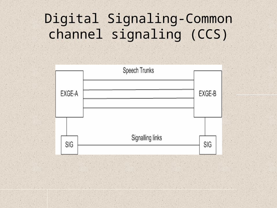
Digital Signaling-Common channel signaling (CCS)

Traffic Engineering
• Telephone traffic is originated by customers and cannot be predicted at all. Any and Every subscriber can originate a call at any and every moment with out giving any previous information and the duration of the calls also not previously known.
• The hour in which the maximum traffic usually occurs in an exchange is known as Busy Hour.
• Busy Hour traffic is the average value of maximum traffic in the busy hour.
Traffic Engineering
• The measurement of traffic should not only consider number of calls but also their duration.
• The duration during which equipments and circuits are held when a call is made is called HOLDING TIME.
• The measurement of traffic flow is the traffic intensity, which is the average number of calls simultaneously in progress and the unit is ERLANG.
Traffic Engineering
• Let C be the total number of calls during the period T, and if the average holding time is ‘t’ hours per call, then
Average Traffic intensity (A)= Ct/T
Traffic Engineering
• Grade of ServiceIt is likely that during busy hour some calls may fail
to mature due to insufficiency of switching equipment.
To ensure that the number of calls so lost is reasonably small, it is the standard practice to provide the switching equipment such that on the average not more than one call out of every 500 in the busy hour is lost at each switching stage.

Traffic Engineering
• This allowable loss is termed the GRADE OF SERVICE and represented by ‘B’
B= 1/500 or B=0.002
GOS = No of calls lost/No of calls offered
It is used for the dimensioning of the exchange equipments.
Traffic Engineering
CCR (Call completion rate) = No of successful calls/No of call attemptsBHCA (Busy Hour Call Attempts) It is the number of call attempts in busy hourBHCR (Busy Hour Call Rate) Average number of calls originated by the
subscribers during BH