Embed Size (px)
Citation preview
TELKOMNIKA, Vol.10, No.4, December 2012, pp. 621~628 ISSN: 1693-6930 accredited by DGHE (DIKTI), Decree No: 51/Dikti/Kep/2010 � 621
Received July 30, 2012; Revised October 29, 2012; Accepted November 7, 2012
Teleautonomous Control on Rescue Robot Prototype
Handy Wicaksono1, Handry Khoswanto1, Son Kuswadi2
1Electrical Engineering Department, Petra Christian University 2Mechatronics Department, Electronics Engineering Polytechnic Institute of Surabaya
e-mail: [email protected], [email protected], [email protected]
Abstrak Aplikasi robot dalam area bencana dapat membantu manusia untuk menyelamatkan korban. Oleh
karena itu, robot harus memiliki mekanisme gerak yang fleksibel sehingga mampu melewati area yang tidak rata dan tidak terstruktur. Penggunaan passive linkage pada rangka robot dapat memberi fleksibilitas yang diperlukan. Pada eksperimen, robot dapat melewati bebatuan kecil dan halangan setinggi 5 cm. Rescue robot juga memiliki kebutuhan kontrol khusus. Selain harus dapat dikendalikan dari jarak jauh oleh operator, robot juga perlu memiliki kemampuan navigasi secara otonom. Metode kontrol teleautonomous merupakan kombinasi kedua metode tersebut. Melalui eksperimen dapat disimpulkan bahwa pada mode teleoperasi, operator harus membiasakan diri untuk melihat lingkungan melalui kamera robot. Sedang pada mode otonom, robot dapat menghindari halangan dan mencari target berdasar sensor dan program yang dibuat. Pada mode teleotonom, robot dapat melakukan pergantian mode kontrol melalui pertukaran data dengan protokol Bluetooth, sehingga kontrol robot lebih fleksibel.
Kata kunci: rescue robot, mekanisme fleksibel, kontrol teleotonom
Abstract Robot application in disaster area can help responder team to save victims. In order to finish task,
robot must have flexible movement mechanism so it can pass through uncluttered area. Passive linkage can be used on robot chassis so it can give robot flexibility. On physical experiments, robot is succeeded to move through gravels and 5 cm obstacle. Rescue robot also has specialized control needs. Robot must able to be controlled remotely. It also must have ability to move autonomously. Teleautonomous control method is combination between those methods. It can be concluded from experiments that on teleoperation mode, operator must get used to see environment through robot’s camera. While on autonomous mode, robot is succeeded to avoid obstacle and search target based on sensor reading and controller program. On teleautonomous mode, robot can change control mode by using bluetooth communication for data transfer, so robot control will be more flexible.
Keywords: rescue robot, flexible mechanism, teleautonomous control 1. Introduction
After earthquake disaster happens, it is very important to search and rescue the trapped victims. Kobe Fire Department mentions that quick search and rescue process is urgent because survival rate of victims are decreasing over the time. Another information from Tokyo Fire Department said that search process is the hardest one. Responder team can save victims if they know where the victims are. Search process often is too difficult for humans, so they need supporting tools to do this [1]. In order to help human team to localize the victims, robot must have small size, high mobility, flexible shape, and it must be equipped with the complete sensors needed [2].
Robot in rescue application must have ability to move through cluttered and unstructured area. In order to support that ability, mechanism which uses passive linkages on robot’s chassis so it has more flexibility to pass on unstructured obstacle. This mechanism has been applied on Shrimp robot [3]. By this research, simplification on frame concept of Shrimp robot will be done to reduce complexity and cost of robot.
Another aspect of rescue robot is its control approach. Robot should have autonomous capability and it also can be controlled teleoperatedly. Combination of those methods is called teleautonomy. This is important to improve flexibility on robot control and increase robot performance. Teleautonomy concept has been suggested and applied on computer simulation
� ISSN: 1693-6930
TELKOMNIKA Vol. 10, No. 4, December 2012 : 621 – 628
622
[4]. It is also applied on dexterous grasping subsystem of robotics hand in bomb disposal and rescue operation [5]. Whereas another researchers has applied weighted teleautonomy to balance teleoperation and autonomy methods on simulated rescue robot [6]. Another goal of this paper is teleautonomous control algorithm implementation on physical robot.
2. Proposed Method 2.1. Flexible Shape on Robot Chassis
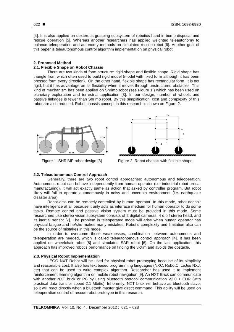
There are two kinds of form structure: rigid shape and flexible shape. Rigid shape has triangle from which often used to build rigid model (model with fixed form although it has been pressed form every direction). On the other hand, flexible shape has rectangular form. It is not rigid, but it has advantage on its flexibility when it moves through unstructured obstacles. This kind of mechanism has been applied on Shrimp robot (see Figure 1.) which has been used on planetary exploration and terrestrial application [3]. In our design, number of wheels and passive linkages is fewer than Shrimp robot. By this simplification, cost and complexity of this robot are also reduced. Robot chassis concept in this research is shown on Figure 2.
Figure 1. SHRIMP robot design [3] Figure 2. Robot chassis with flexible shape
2.2. Teleautonomous Control Approach Generally, there are two robot control approaches: autonomous and teleoperation.
Autonomous robot can behave independently from human operator (i.e. industrial robot on car manufacturing). It will act exactly same as action that asked by controller program. But robot likely will fail to operate autonomously in noisy and uncertain environment (i.e. earthquake disaster area).
Robot also can be remotely controlled by human operator. In this mode, robot doesn’t have intelligence at all because it only acts as interface medium for human operator to do some tasks. Remote control and passive vision system must be provided in this mode. Some researchers use stereo vision subsystem consists of 2 digital cameras, 4 d.o.f stereo head, and its inertial sensor [7]. The problem in teleoperated mode will arise when human operator has physical fatigue and he/she makes many mistakes. Robot’s complexity and limitation also can be the source of mistakes in this mode.
In order to overcome those weaknesses, combination between autonomous and teleoperation are needed, which is called teleautonomous control approach [4]. It has been applied on wheelchair robot [8] and simulated SAR robot [6]. On the last application, this approach has improved robot’s performance on finding the victim and avoids the obstacle.
2.3. Physical Robot Implementation
LEGO NXT Robot will be used for physical robot prototyping because of its simplicity and reasonable cost. It also has text based programming languages (NXC, RobotC, LeJos NXJ, etc) that can be used to write complex algorithm. Researcher has used it to implement reinforcement learning algorithm on mobile robot navigation [9]. An NXT Brick can communicate with another NXT brick or PC by using bluetooth protocol communication V2.0 + EDR (with practical data transfer speed 2.1 Mbit/s). Inherently, NXT brick will behave as bluetooth slave, so it will react directly when a bluetooh master give direct command. This ability will be used on teleoperation control of rescue robot prototype in this research.
TELKOMNIKA ISSN: 1693-6930 �
Teleautonomous Control on Rescue Robot Prototype (Handy Wicaksono)
623
3. Research Method 3.1 General Block Diagram
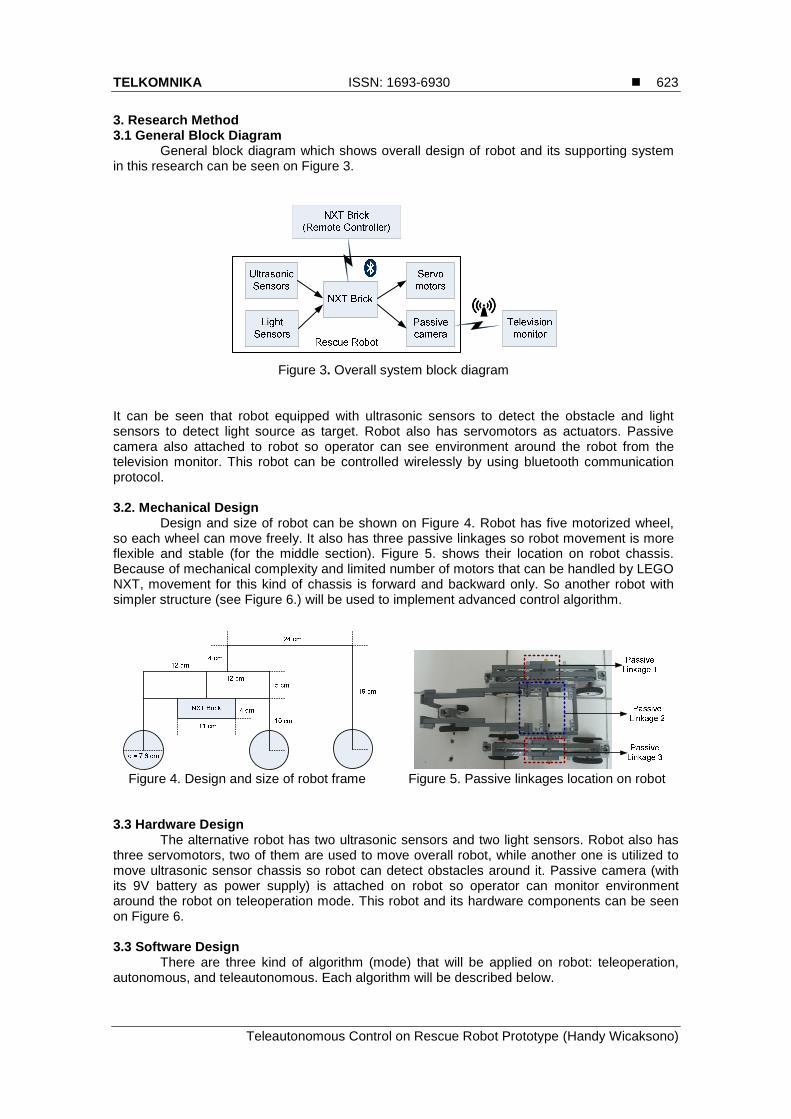
General block diagram which shows overall design of robot and its supporting system in this research can be seen on Figure 3.
Figure 3. Overall system block diagram
It can be seen that robot equipped with ultrasonic sensors to detect the obstacle and light sensors to detect light source as target. Robot also has servomotors as actuators. Passive camera also attached to robot so operator can see environment around the robot from the television monitor. This robot can be controlled wirelessly by using bluetooth communication protocol. 3.2. Mechanical Design
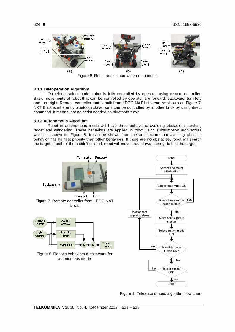
Design and size of robot can be shown on Figure 4. Robot has five motorized wheel, so each wheel can move freely. It also has three passive linkages so robot movement is more flexible and stable (for the middle section). Figure 5. shows their location on robot chassis. Because of mechanical complexity and limited number of motors that can be handled by LEGO NXT, movement for this kind of chassis is forward and backward only. So another robot with simpler structure (see Figure 6.) will be used to implement advanced control algorithm.
Figure 4. Design and size of robot frame Figure 5. Passive linkages location on robot
3.3 Hardware Design The alternative robot has two ultrasonic sensors and two light sensors. Robot also has
three servomotors, two of them are used to move overall robot, while another one is utilized to move ultrasonic sensor chassis so robot can detect obstacles around it. Passive camera (with its 9V battery as power supply) is attached on robot so operator can monitor environment around the robot on teleoperation mode. This robot and its hardware components can be seen on Figure 6. 3.3 Software Design
There are three kind of algorithm (mode) that will be applied on robot: teleoperation, autonomous, and teleautonomous. Each algorithm will be described below.
� ISSN: 1693-6930
TELKOMNIKA Vol. 10, No. 4, December 2012 : 621 – 628
624
(a) (b) (c)
Figure 6. Robot and its hardware components
3.3.1 Teleoperation Algorithm On teleoperation mode, robot is fully controlled by operator using remote controller.
Basic movements of robot that can be controlled by operator are forward, backward, turn left, and turn right. Remote controller that is built from LEGO NXT brick can be shown on Figure 7. NXT Brick is inherently bluetooth slave, so it can be controlled by another brick by using direct command. It means that no script needed on bluetooth slave. 3.3.2 Autonomous Algorithm
Robot in autonomous mode will have three behaviors: avoiding obstacle, searching target and wandering. These behaviors are applied in robot using subsumption architecture which is shown on Figure 8. It can be shown from the architecture that avoiding obstacle behavior has highest prioirity than other behaviors. If there are no obstacles, robot will search the target. If both of them didn’t existed, robot will move around (wandering) to find the target.
Figure 7. Remote controller from LEGO NXT
brick
Figure 9. Teleautonomous algorithm flow chart
Figure 8. Robot’s behaviors architecture for autonomous mode
Sensor and motor
initialization
Is robot succeed to
reach target?
Teleoperation mode
ON
Autonomous Mode ON
Is switch mode
button ON?
Is exit button
ON?
Start
Stop
No
Yes
No
Yes
No
Yes
Slave sent signal to
master
Master sent
signal to slave

TELKOMNIKA ISSN: 1693-6930 �
Teleautonomous Control on Rescue Robot Prototype (Handy Wicaksono)
625
3.3.3 Teleautonomous Algorithm Teleautonomous mode needed to overcome weaknesses of those modes used before.
It combines the usage of autonomous and teleoperation mode. First of all, robot will use autonomous mode. If it is succeeded to reach the target, it will sent signal to remote controller and activate teleoperation mode so operator can move the robot back to the start area. Flow chart of this mode can be seen on Figure 9. 4. Results and Analysis
This section will explain about the experiment results on robot mechanic and its control algorithm. 4.1 Robot Mechanic
On this experiment, robot with passive linkages will be used. Robot will be tested to move on gravels. The results are shown on Figure 10. (a) – (d). It also has to move on 5 cm wooden block. Robot’s wheel must be modified to increase its friction force and section area. Figure 11. shows the old and new wheel configuration. Experiment results on robot that move on 5 cm wooden block are shown on Figure 12. It can pass the test successfully.
(a) (b) (c) (d)
Figure 10. Robot moves on gravels
(a) (b)
Figure 11. Robot’s wheel configuration
(a) (b) (c) (d)
Figure 12. Robot move on 5 centimeters wooden block
4.2 Control Algorithm Experiment Because of physical limitation on rescue robot with passive linkages, another robot will
be used for control algorithm experiment (see Figure 6.). Experiment arena has 120 x 150 cm size (it consists of 20 squares, which each size is 30 x 30 cm). It has two start area and one target area (lamp area). It is shown on Figure 13. 4.2.1 Teleoperation Control Experiment
First control mode will be used is teleoperation mode. In this mode, robot will be fully controlled by operator wirelessly using bluetooth protocol communication. Operator only needs to see the television which shows video result from the robot’s camera. Television is equipped
� ISSN: 1693-6930
TELKOMNIKA Vol. 10, No. 4, December 2012 : 621 – 628
626
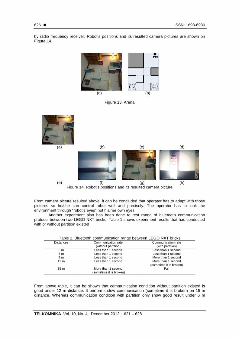
by radio frequency receiver. Robot’s positions and its resulted camera pictures are shown on Figure 14.
(a) (b)
Figure 13. Arena
(a) (b) (c) (d)
(e) (f) (g) (h)
Figure 14. Robot’s positions and its resulted camera picture From camera picture resulted above, it can be concluded that operator has to adapt with those pictures so he/she can control robot well and precisely. The operator has to look the environment through “robot’s eyes” not his/her own eyes.
Another experiment also has been done to test range of bluetooth communication protocol between two LEGO NXT bricks. Table 1 shows experiment results that has conducted with or without partition existed
Table 1. Bluetooth communication range between LEGO NXT bricks Distances Communication rate
(without partition) Communication rate
(with partition) 3 m Less than 1 second Less than 1 second 6 m Less than 1 second Less than 1 second 9 m Less than 1 second More than 1 second
12 m Less than 1 second More than 1 second (sometime it is broken)
15 m More than 1 second (sometime it is broken)
Fail
From above table, it can be shown that communication condition without partition existed is good under 12 m distance. It performs slow communication (sometime it is broken) on 15 m distance. Whereas communication condition with partition only show good result under 6 m
TELKOMNIKA
Teleautonomous Control on Rescue Robot Prototype
distance. It is getting slower on 9 m distance, and sometime it performon 12 m distance. Moreover, it fail 4.2.2 Autonomous Control Experiment
On this experiment robot will move autonomously. Arena will be used here. Routes that warea are shown on Figure 15. These routes there are some differences in the real world experiment because of friction force of arena, slippage on robot’s wheel, and inaccuracy on sensor rea
Start Area 1
Figure 15. Robot’s route from start area 1 and
4.2.3 Teleautonomous Control ExperimentTeleautonomous control has been applied based on its flow chart
section. On this experiment, robot succeedteleoperation) to remote controller after the robot find the target. After that, operator can fully control the robot to go back to the start area.not control robot at all. Figure 16. (a) autonomous mode (mode 0)teleoperation mode (mode 1).
On teleoperation mode (mode 1), operator can control robot by using NXT brick button. When he/she push the orange (middle) button “jStr” variable will change to 1 and robot will move straight. Same variable will change to 2 (robot turns right) and 3 (robot right gray and left gray buttons are pushed. Screen of master and slave NXT bricks when the buttons are pressed shown on Figure 17.
(a)
Figure 16. Screens of NXT master
(a)
Figure 17. Screen of master and slave NXT bricks when buttons are pressed
ISSN: 1693-6930
Teleautonomous Control on Rescue Robot Prototype (Handy Wicaksono
distance. It is getting slower on 9 m distance, and sometime it performs broken communication nce. Moreover, it fails to communicate on 15 m distance.
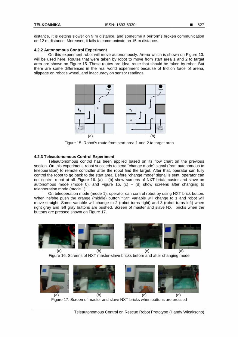
4.2.2 Autonomous Control Experiment On this experiment robot will move autonomously. Arena which is shown on Figure 13.
will be used here. Routes that were taken by robot to move from start area 1 area are shown on Figure 15. These routes are ideal route that should be taken by robot. But there are some differences in the real world experiment because of friction force of arena, slippage on robot’s wheel, and inaccuracy on sensor readings.
Target
Target
Start Area 2
(a) (b)
Figure 15. Robot’s route from start area 1 and 2 to target area
4.2.3 Teleautonomous Control Experiment Teleautonomous control has been applied based on its flow chart
section. On this experiment, robot succeeds to send “change mode” signal (from autonomous to teleoperation) to remote controller after the robot find the target. After that, operator can fully control the robot to go back to the start area. Before “change mode” signal is sent, operator can
all. Figure 16. (a) – (b) show screens of NXT brick master and slave on autonomous mode (mode 0), and Figure 16. (c) – (d) show screens after changing to teleoperation mode (mode 1).
n teleoperation mode (mode 1), operator can control robot by using NXT brick button. When he/she push the orange (middle) button “jStr” variable will change to 1 and robot will move straight. Same variable will change to 2 (robot turns right) and 3 (robot right gray and left gray buttons are pushed. Screen of master and slave NXT bricks when the buttons are pressed shown on Figure 17.
(b) (c)
Figure 16. Screens of NXT master-slave bricks before and after changing mode
(b) (c)
Figure 17. Screen of master and slave NXT bricks when buttons are pressed
�
Handy Wicaksono)
627
broken communication
shown on Figure 13. taken by robot to move from start area 1 and 2 to target
ideal route that should be taken by robot. But there are some differences in the real world experiment because of friction force of arena,
2 to target area
Teleautonomous control has been applied based on its flow chart on the previous to send “change mode” signal (from autonomous to
teleoperation) to remote controller after the robot find the target. After that, operator can fully Before “change mode” signal is sent, operator can
screens of NXT brick master and slave on screens after changing to
n teleoperation mode (mode 1), operator can control robot by using NXT brick button. When he/she push the orange (middle) button “jStr” variable will change to 1 and robot will move straight. Same variable will change to 2 (robot turns right) and 3 (robot turns left) when right gray and left gray buttons are pushed. Screen of master and slave NXT bricks when the
(d)
changing mode
(d)
Figure 17. Screen of master and slave NXT bricks when buttons are pressed
� ISSN: 1693-6930
TELKOMNIKA Vol. 10, No. 4, December 2012 : 621 – 628
628
5. Conclusion It can be concluded that implementation of flexible shape on chassis of rescue robot
prototype has given more flexibility on robot’s movement. It is succeeded to move through obstacle (gravels, 5 cm wooden blocks) and keep middle section of robot stable at the same time. Three control modes (teleoperation, autonomous, teleautonomous) have been applied successfully. On teleoperation mode, operator have very important role, so he/she must get used to see environment through robot’s camera. Whereas on the autonomous mode, robot is succeeded to avoid obstacle and search target based on sensor reading and controller program. On teleautonomous mode, robot can change control mode by using bluetooth communication for data transfer, so robot control will be more flexible. Acknowledgement This work is being supported by LPPM – Petra Christian University through “Internal Grant” with contract number 07/Sugas-Pen/LPPM-UKP/2011. References [1] Tadokoro S. Rescue Robotics - DDT Project on Robots and Systems for Urban Search and Rescue.
Springer. 2009. [2] Murphy R. Casper J. Hyams J. Micire M. Minten B. Mobility and Sensing Demand in USAR. IEEE
International Conference on Industrial Electronics, Control, and Instrumentation. 2000. [3] Siegwart R. Lamon P. Estier T. Lauria M. Piguet R. Innovative Design for Wheeled Locomotion in
Rough Terrain. Robotics and Autonomous Systems Journal. 2002; 40(2-3): 151 – 162. [4] Arkin RC. Ali K. Integration of Reactive and Telerobotic Control in Multi-agent Robotic Systems. Proc.
Third International Conference on Simulation of Adaptive Behavior, (SAB94) [From Animals to Animats]. Brighton, England. 1994: 473-478.
[5] Beltran C. Gasteratos A. Amanatiadis A. Chrysostomou D. Guzman R. Toth A. Szollosi L. Juhasz A. and Galambos P. Methods and Techniques for Intelligent Navigation and Manipulation for Bomb Disposal and Rescue Operations. IEEE International Workshop on Safety Security and Rescue Robotics. Rome, Italy. 2007.
[6] Wegner R. Anderson J. Agent-based Support for Balancing Teleoperation and Autonomy in Urban Search and Rescue. International Journal of Robotics and Automation. 2006; 21(2): 120-128.
[7] Amanatiadis A, Gasteratos A. Stereo Vision System for Remotely Operated Robots. In: Mollet N. Editor. Remote and Telerobotics. InTech; 2010: 59-72.
[8] Argyros A. Georgiadis P. Trahanias P. Tsakiris D. Semi-autonomous Navigation of a Robotic Wheelchair. Journal of Intelligent and Robotic Systems. 2002; 34(3): 315-329.
[9] Wicaksono H. Khoswanto H. Kuswadi S. Behaviors Coordination and Learning on Autonomous Navigation of Physical Robot. TELKOMNIKA. 2011; 9(3): 473-482.