Embed Size (px)
Citation preview

Tektronix 4000 SeriesDigital Phosphor OscilloscopesUser Manual
www.tektronix.com071-2121-01

Copyright © Tektronix. All rights reserved. Licensed software products are owned by Tektronix or its subsidiaries or suppliers, and are protected bynational copyright laws and international treaty provisions.
Tektronix products are covered by U.S. and foreign patents, issued and pending. Information in this publication supersedes that in all previouslypublished material. Specifications and price change privileges reserved.
TEKTRONIX and TEK are registered trademarks of Tektronix, Inc.
e*Scope, iView, OpenChoice, TekSecure, and TekVPI are registered trademarks of Tektronix, Inc.
MagniVu and Wave Inspector are trademarks of Tektronix, Inc.
Tektronix is an authorized licensee of the CompactFlash® trademark.
Contacting TektronixTektronix, Inc.14200 SW Karl Braun DriveP.O. Box 500Beaverton, OR 97077USA
For product information, sales, service, and technical support:In North America, call 1-800-833-9200.Worldwide, visit www.tektronix.com to find contacts in your area.

Warranty 16Tektronix warrants that the product will be free from defects in materials and workmanship for a period of three (3) years from the date of originalpurchase from an authorized Tektronix distributor. If the product proves defective during this warranty period, Tektronix, at its option, either willrepair the defective product without charge for parts and labor, or will provide a replacement in exchange for the defective product. Batteries areexcluded from this warranty. Parts, modules and replacement products used by Tektronix for warranty work may be new or reconditioned to likenew performance. All replaced parts, modules and products become the property of Tektronix.
In order to obtain service under this warranty, Customer must notify Tektronix of the defect before the expiration of the warranty period and makesuitable arrangements for the performance of service. Customer shall be responsible for packaging and shipping the defective product to the servicecenter designated by Tektronix, shipping charges prepaid, and with a copy of customer proof of purchase. Tektronix shall pay for the return of theproduct to Customer if the shipment is to a location within the country in which the Tektronix service center is located. Customer shall be responsiblefor paying all shipping charges, duties, taxes, and any other charges for products returned to any other locations.
This warranty shall not apply to any defect, failure or damage caused by improper use or improper or inadequate maintenance and care. Tektronixshall not be obligated to furnish service under this warranty a) to repair damage resulting from attempts by personnel other than Tektronixrepresentatives to install, repair or service the product; b) to repair damage resulting from improper use or connection to incompatible equipment; c) torepair any damage or malfunction caused by the use of non-Tektronix supplies; or d) to service a product that has been modified or integrated withother products when the effect of such modification or integration increases the time or difficulty of servicing the product.
THIS WARRANTY IS GIVEN BY TEKTRONIX WITH RESPECT TO THE PRODUCT IN LIEU OF ANY OTHER WARRANTIES, EXPRESS ORIMPLIED. TEKTRONIX AND ITS VENDORS DISCLAIM ANY IMPLIED WARRANTIES OF MERCHANTABILITY OR FITNESS FOR A PARTICULARPURPOSE. TEKTRONIX’ RESPONSIBILITY TO REPAIR OR REPLACE DEFECTIVE PRODUCTS IS THE SOLE AND EXCLUSIVE REMEDYPROVIDED TO THE CUSTOMER FOR BREACH OF THIS WARRANTY. TEKTRONIX AND ITS VENDORS WILL NOT BE LIABLE FOR ANYINDIRECT, SPECIAL, INCIDENTAL, OR CONSEQUENTIAL DAMAGES IRRESPECTIVE OF WHETHER TEKTRONIX OR THE VENDOR HASADVANCE NOTICE OF THE POSSIBILITY OF SUCH DAMAGES.


Table of Contents
Table of ContentsGeneral Safety Summary . . . . . . . . . . . . . . . . . . . . . . . . . . . . . . . . . . . . . . . . . . . . . . . . . . . . . . . . . . . . . . . . . . . . . . . . . . . . . . . . . . . . . . . . . . . . . . . . . . . . . . . . . . . . . . . . . . . v
Environmental Considerations . . . . . . . . . . . . . . . . . . . . . . . . . . . . . . . . . . . . . . . . . . . . . . . . . . . . . . . . . . . . . . . . . . . . . . . . . . . . . . . . . . . . . . . . . . . . . . . . . . . . . . . . . . . . viii
Preface. . . . . . . . . . . . . . . . . . . . . . . . . . . . . . . . . . . . . . . . . . . . . . . . . . . . . . . . . . . . . . . . . . . . . . . . . . . . . . . . . . . . . . . . . . . . . . . . . . . . . . . . . . . . . . . . . . . . . . . . . . . . . . . . . . . . . . . xKey Features. . . . . . . . . . . . . . . . . . . . . . . . . . . . . . . . . . . . . . . . . . . . . . . . . . . . . . . . . . . . . . . . . . . . . . . . . . . . . . . . . . . . . . . . . . . . . . . . . . . . . . . . . . . . . . . . . . . . . . . . . . . xWhere to Find More Information. . . . . . . . . . . . . . . . . . . . . . . . . . . . . . . . . . . . . . . . . . . . . . . . . . . . . . . . . . . . . . . . . . . . . . . . . . . . . . . . . . . . . . . . . . . . . . . . . . . . . xiiConventions Used in This Manual. . . . . . . . . . . . . . . . . . . . . . . . . . . . . . . . . . . . . . . . . . . . . . . . . . . . . . . . . . . . . . . . . . . . . . . . . . . . . . . . . . . . . . . . . . . . . . . . . . . xiii
Installation . . . . . . . . . . . . . . . . . . . . . . . . . . . . . . . . . . . . . . . . . . . . . . . . . . . . . . . . . . . . . . . . . . . . . . . . . . . . . . . . . . . . . . . . . . . . . . . . . . . . . . . . . . . . . . . . . . . . . . . . . . . . . . . . . . 1Before Installation. . . . . . . . . . . . . . . . . . . . . . . . . . . . . . . . . . . . . . . . . . . . . . . . . . . . . . . . . . . . . . . . . . . . . . . . . . . . . . . . . . . . . . . . . . . . . . . . . . . . . . . . . . . . . . . . . . . . . 1Operating Considerations . . . . . . . . . . . . . . . . . . . . . . . . . . . . . . . . . . . . . . . . . . . . . . . . . . . . . . . . . . . . . . . . . . . . . . . . . . . . . . . . . . . . . . . . . . . . . . . . . . . . . . . . . . . . 7Connecting Probes . . . . . . . . . . . . . . . . . . . . . . . . . . . . . . . . . . . . . . . . . . . . . . . . . . . . . . . . . . . . . . . . . . . . . . . . . . . . . . . . . . . . . . . . . . . . . . . . . . . . . . . . . . . . . . . . . . 12Securing the Oscilloscope . . . . . . . . . . . . . . . . . . . . . . . . . . . . . . . . . . . . . . . . . . . . . . . . . . . . . . . . . . . . . . . . . . . . . . . . . . . . . . . . . . . . . . . . . . . . . . . . . . . . . . . . . . . 15Powering On the Oscilloscope . . . . . . . . . . . . . . . . . . . . . . . . . . . . . . . . . . . . . . . . . . . . . . . . . . . . . . . . . . . . . . . . . . . . . . . . . . . . . . . . . . . . . . . . . . . . . . . . . . . . . . 16Powering Off the Oscilloscope . . . . . . . . . . . . . . . . . . . . . . . . . . . . . . . . . . . . . . . . . . . . . . . . . . . . . . . . . . . . . . . . . . . . . . . . . . . . . . . . . . . . . . . . . . . . . . . . . . . . . . 18Functional Check . . . . . . . . . . . . . . . . . . . . . . . . . . . . . . . . . . . . . . . . . . . . . . . . . . . . . . . . . . . . . . . . . . . . . . . . . . . . . . . . . . . . . . . . . . . . . . . . . . . . . . . . . . . . . . . . . . . . 19Compensating a Passive Voltage Probe . . . . . . . . . . . . . . . . . . . . . . . . . . . . . . . . . . . . . . . . . . . . . . . . . . . . . . . . . . . . . . . . . . . . . . . . . . . . . . . . . . . . . . . . . . . . 22Application Module Free Trial . . . . . . . . . . . . . . . . . . . . . . . . . . . . . . . . . . . . . . . . . . . . . . . . . . . . . . . . . . . . . . . . . . . . . . . . . . . . . . . . . . . . . . . . . . . . . . . . . . . . . . . 25Installing an Application Module . . . . . . . . . . . . . . . . . . . . . . . . . . . . . . . . . . . . . . . . . . . . . . . . . . . . . . . . . . . . . . . . . . . . . . . . . . . . . . . . . . . . . . . . . . . . . . . . . . . . . 25Changing the User Interface Language . . . . . . . . . . . . . . . . . . . . . . . . . . . . . . . . . . . . . . . . . . . . . . . . . . . . . . . . . . . . . . . . . . . . . . . . . . . . . . . . . . . . . . . . . . . . . 26Changing the Date and Time . . . . . . . . . . . . . . . . . . . . . . . . . . . . . . . . . . . . . . . . . . . . . . . . . . . . . . . . . . . . . . . . . . . . . . . . . . . . . . . . . . . . . . . . . . . . . . . . . . . . . . . . 29Signal Path Compensation . . . . . . . . . . . . . . . . . . . . . . . . . . . . . . . . . . . . . . . . . . . . . . . . . . . . . . . . . . . . . . . . . . . . . . . . . . . . . . . . . . . . . . . . . . . . . . . . . . . . . . . . . . 31Upgrading Firmware . . . . . . . . . . . . . . . . . . . . . . . . . . . . . . . . . . . . . . . . . . . . . . . . . . . . . . . . . . . . . . . . . . . . . . . . . . . . . . . . . . . . . . . . . . . . . . . . . . . . . . . . . . . . . . . . . 34
Tektronix 4000 Series Oscilloscopes User Manual i

Table of Contents
Connecting Your Oscilloscope to a Computer . . . . . . . . . . . . . . . . . . . . . . . . . . . . . . . . . . . . . . . . . . . . . . . . . . . . . . . . . . . . . . . . . . . . . . . . . . . . . . . . . . . . . . 41Connecting a USB Keyboard to Your Oscilloscope . . . . . . . . . . . . . . . . . . . . . . . . . . . . . . . . . . . . . . . . . . . . . . . . . . . . . . . . . . . . . . . . . . . . . . . . . . . . . . . . . 49
Get Acquainted with the Instrument. . . . . . . . . . . . . . . . . . . . . . . . . . . . . . . . . . . . . . . . . . . . . . . . . . . . . . . . . . . . . . . . . . . . . . . . . . . . . . . . . . . . . . . . . . . . . . . . . . . . . . . 51Front-Panel Menus and Controls . . . . . . . . . . . . . . . . . . . . . . . . . . . . . . . . . . . . . . . . . . . . . . . . . . . . . . . . . . . . . . . . . . . . . . . . . . . . . . . . . . . . . . . . . . . . . . . . . . . . 51Front-Panel Connectors . . . . . . . . . . . . . . . . . . . . . . . . . . . . . . . . . . . . . . . . . . . . . . . . . . . . . . . . . . . . . . . . . . . . . . . . . . . . . . . . . . . . . . . . . . . . . . . . . . . . . . . . . . . . . 75Side-Panel Connector . . . . . . . . . . . . . . . . . . . . . . . . . . . . . . . . . . . . . . . . . . . . . . . . . . . . . . . . . . . . . . . . . . . . . . . . . . . . . . . . . . . . . . . . . . . . . . . . . . . . . . . . . . . . . . . 76Rear-Panel Connectors. . . . . . . . . . . . . . . . . . . . . . . . . . . . . . . . . . . . . . . . . . . . . . . . . . . . . . . . . . . . . . . . . . . . . . . . . . . . . . . . . . . . . . . . . . . . . . . . . . . . . . . . . . . . . . 77
Acquire the Signal . . . . . . . . . . . . . . . . . . . . . . . . . . . . . . . . . . . . . . . . . . . . . . . . . . . . . . . . . . . . . . . . . . . . . . . . . . . . . . . . . . . . . . . . . . . . . . . . . . . . . . . . . . . . . . . . . . . . . . . . . 79Setting Up Analog Channels . . . . . . . . . . . . . . . . . . . . . . . . . . . . . . . . . . . . . . . . . . . . . . . . . . . . . . . . . . . . . . . . . . . . . . . . . . . . . . . . . . . . . . . . . . . . . . . . . . . . . . . . 79Using the Default Setup . . . . . . . . . . . . . . . . . . . . . . . . . . . . . . . . . . . . . . . . . . . . . . . . . . . . . . . . . . . . . . . . . . . . . . . . . . . . . . . . . . . . . . . . . . . . . . . . . . . . . . . . . . . . . 86Using Autoset . . . . . . . . . . . . . . . . . . . . . . . . . . . . . . . . . . . . . . . . . . . . . . . . . . . . . . . . . . . . . . . . . . . . . . . . . . . . . . . . . . . . . . . . . . . . . . . . . . . . . . . . . . . . . . . . . . . . . . . . 87Acquisition Concepts . . . . . . . . . . . . . . . . . . . . . . . . . . . . . . . . . . . . . . . . . . . . . . . . . . . . . . . . . . . . . . . . . . . . . . . . . . . . . . . . . . . . . . . . . . . . . . . . . . . . . . . . . . . . . . . . 89How the Analog Acquisition Modes Work . . . . . . . . . . . . . . . . . . . . . . . . . . . . . . . . . . . . . . . . . . . . . . . . . . . . . . . . . . . . . . . . . . . . . . . . . . . . . . . . . . . . . . . . . . . 92Changing the Acquisition Mode and Record Length. . . . . . . . . . . . . . . . . . . . . . . . . . . . . . . . . . . . . . . . . . . . . . . . . . . . . . . . . . . . . . . . . . . . . . . . . . . . . . . . 94Using Roll Mode . . . . . . . . . . . . . . . . . . . . . . . . . . . . . . . . . . . . . . . . . . . . . . . . . . . . . . . . . . . . . . . . . . . . . . . . . . . . . . . . . . . . . . . . . . . . . . . . . . . . . . . . . . . . . . . . . . . . . 97Setting Up a Serial or Parallel Bus . . . . . . . . . . . . . . . . . . . . . . . . . . . . . . . . . . . . . . . . . . . . . . . . . . . . . . . . . . . . . . . . . . . . . . . . . . . . . . . . . . . . . . . . . . . . . . . . . . 98Setting Up Digital Channels . . . . . . . . . . . . . . . . . . . . . . . . . . . . . . . . . . . . . . . . . . . . . . . . . . . . . . . . . . . . . . . . . . . . . . . . . . . . . . . . . . . . . . . . . . . . . . . . . . . . . . . . 110When and Why to Turn On MagniVu . . . . . . . . . . . . . . . . . . . . . . . . . . . . . . . . . . . . . . . . . . . . . . . . . . . . . . . . . . . . . . . . . . . . . . . . . . . . . . . . . . . . . . . . . . . . . . . 114Using MagniVu . . . . . . . . . . . . . . . . . . . . . . . . . . . . . . . . . . . . . . . . . . . . . . . . . . . . . . . . . . . . . . . . . . . . . . . . . . . . . . . . . . . . . . . . . . . . . . . . . . . . . . . . . . . . . . . . . . . . . . 115
Trigger Setup . . . . . . . . . . . . . . . . . . . . . . . . . . . . . . . . . . . . . . . . . . . . . . . . . . . . . . . . . . . . . . . . . . . . . . . . . . . . . . . . . . . . . . . . . . . . . . . . . . . . . . . . . . . . . . . . . . . . . . . . . . . . . 117Triggering Concepts . . . . . . . . . . . . . . . . . . . . . . . . . . . . . . . . . . . . . . . . . . . . . . . . . . . . . . . . . . . . . . . . . . . . . . . . . . . . . . . . . . . . . . . . . . . . . . . . . . . . . . . . . . . . . . . . 117Choosing a Trigger Type. . . . . . . . . . . . . . . . . . . . . . . . . . . . . . . . . . . . . . . . . . . . . . . . . . . . . . . . . . . . . . . . . . . . . . . . . . . . . . . . . . . . . . . . . . . . . . . . . . . . . . . . . . . . 124Selecting Triggers. . . . . . . . . . . . . . . . . . . . . . . . . . . . . . . . . . . . . . . . . . . . . . . . . . . . . . . . . . . . . . . . . . . . . . . . . . . . . . . . . . . . . . . . . . . . . . . . . . . . . . . . . . . . . . . . . . . 126
ii Tektronix 4000 Series Oscilloscopes User Manual

Table of Contents
Triggering on Buses . . . . . . . . . . . . . . . . . . . . . . . . . . . . . . . . . . . . . . . . . . . . . . . . . . . . . . . . . . . . . . . . . . . . . . . . . . . . . . . . . . . . . . . . . . . . . . . . . . . . . . . . . . . . . . . . 132Checking Trigger Settings . . . . . . . . . . . . . . . . . . . . . . . . . . . . . . . . . . . . . . . . . . . . . . . . . . . . . . . . . . . . . . . . . . . . . . . . . . . . . . . . . . . . . . . . . . . . . . . . . . . . . . . . . . 141Using Sequence Trigger (A (Main) and B (Delayed)) . . . . . . . . . . . . . . . . . . . . . . . . . . . . . . . . . . . . . . . . . . . . . . . . . . . . . . . . . . . . . . . . . . . . . . . . . . . . . . 142Starting and Stopping an Acquisition. . . . . . . . . . . . . . . . . . . . . . . . . . . . . . . . . . . . . . . . . . . . . . . . . . . . . . . . . . . . . . . . . . . . . . . . . . . . . . . . . . . . . . . . . . . . . . . 145
Display Waveform Data . . . . . . . . . . . . . . . . . . . . . . . . . . . . . . . . . . . . . . . . . . . . . . . . . . . . . . . . . . . . . . . . . . . . . . . . . . . . . . . . . . . . . . . . . . . . . . . . . . . . . . . . . . . . . . . . . . 146Adding and Removing a Waveform . . . . . . . . . . . . . . . . . . . . . . . . . . . . . . . . . . . . . . . . . . . . . . . . . . . . . . . . . . . . . . . . . . . . . . . . . . . . . . . . . . . . . . . . . . . . . . . . 146Setting the Display Style and Persistence . . . . . . . . . . . . . . . . . . . . . . . . . . . . . . . . . . . . . . . . . . . . . . . . . . . . . . . . . . . . . . . . . . . . . . . . . . . . . . . . . . . . . . . . . 147Setting Waveform Intensity . . . . . . . . . . . . . . . . . . . . . . . . . . . . . . . . . . . . . . . . . . . . . . . . . . . . . . . . . . . . . . . . . . . . . . . . . . . . . . . . . . . . . . . . . . . . . . . . . . . . . . . . . 152Scaling and Positioning a Waveform . . . . . . . . . . . . . . . . . . . . . . . . . . . . . . . . . . . . . . . . . . . . . . . . . . . . . . . . . . . . . . . . . . . . . . . . . . . . . . . . . . . . . . . . . . . . . . . 154Setting Input Parameters . . . . . . . . . . . . . . . . . . . . . . . . . . . . . . . . . . . . . . . . . . . . . . . . . . . . . . . . . . . . . . . . . . . . . . . . . . . . . . . . . . . . . . . . . . . . . . . . . . . . . . . . . . . 156Positioning and Labeling Bus Signals . . . . . . . . . . . . . . . . . . . . . . . . . . . . . . . . . . . . . . . . . . . . . . . . . . . . . . . . . . . . . . . . . . . . . . . . . . . . . . . . . . . . . . . . . . . . . . 161Positioning, Scaling, and Grouping Digital Channels . . . . . . . . . . . . . . . . . . . . . . . . . . . . . . . . . . . . . . . . . . . . . . . . . . . . . . . . . . . . . . . . . . . . . . . . . . . . . . 163Viewing Digital Channels . . . . . . . . . . . . . . . . . . . . . . . . . . . . . . . . . . . . . . . . . . . . . . . . . . . . . . . . . . . . . . . . . . . . . . . . . . . . . . . . . . . . . . . . . . . . . . . . . . . . . . . . . . . 167
Analyze Waveform Data. . . . . . . . . . . . . . . . . . . . . . . . . . . . . . . . . . . . . . . . . . . . . . . . . . . . . . . . . . . . . . . . . . . . . . . . . . . . . . . . . . . . . . . . . . . . . . . . . . . . . . . . . . . . . . . . . . 168Taking Automatic Measurements. . . . . . . . . . . . . . . . . . . . . . . . . . . . . . . . . . . . . . . . . . . . . . . . . . . . . . . . . . . . . . . . . . . . . . . . . . . . . . . . . . . . . . . . . . . . . . . . . . . 168Selecting Automatic Measurements. . . . . . . . . . . . . . . . . . . . . . . . . . . . . . . . . . . . . . . . . . . . . . . . . . . . . . . . . . . . . . . . . . . . . . . . . . . . . . . . . . . . . . . . . . . . . . . . 171Customizing an Automatic Measurement . . . . . . . . . . . . . . . . . . . . . . . . . . . . . . . . . . . . . . . . . . . . . . . . . . . . . . . . . . . . . . . . . . . . . . . . . . . . . . . . . . . . . . . . . . 177Taking Manual Measurements with Cursors . . . . . . . . . . . . . . . . . . . . . . . . . . . . . . . . . . . . . . . . . . . . . . . . . . . . . . . . . . . . . . . . . . . . . . . . . . . . . . . . . . . . . . . 185Using Math Waveforms . . . . . . . . . . . . . . . . . . . . . . . . . . . . . . . . . . . . . . . . . . . . . . . . . . . . . . . . . . . . . . . . . . . . . . . . . . . . . . . . . . . . . . . . . . . . . . . . . . . . . . . . . . . . . 191Using FFT . . . . . . . . . . . . . . . . . . . . . . . . . . . . . . . . . . . . . . . . . . . . . . . . . . . . . . . . . . . . . . . . . . . . . . . . . . . . . . . . . . . . . . . . . . . . . . . . . . . . . . . . . . . . . . . . . . . . . . . . . . . 194Using Advanced Math . . . . . . . . . . . . . . . . . . . . . . . . . . . . . . . . . . . . . . . . . . . . . . . . . . . . . . . . . . . . . . . . . . . . . . . . . . . . . . . . . . . . . . . . . . . . . . . . . . . . . . . . . . . . . . 198Using Reference Waveforms . . . . . . . . . . . . . . . . . . . . . . . . . . . . . . . . . . . . . . . . . . . . . . . . . . . . . . . . . . . . . . . . . . . . . . . . . . . . . . . . . . . . . . . . . . . . . . . . . . . . . . . 200
Tektronix 4000 Series Oscilloscopes User Manual iii

Table of Contents
Using Wave Inspector to Manage Long Record Length Waveforms . . . . . . . . . . . . . . . . . . . . . . . . . . . . . . . . . . . . . . . . . . . . . . . . . . . . . . . . . . . . . . 203
Save and Recall Information . . . . . . . . . . . . . . . . . . . . . . . . . . . . . . . . . . . . . . . . . . . . . . . . . . . . . . . . . . . . . . . . . . . . . . . . . . . . . . . . . . . . . . . . . . . . . . . . . . . . . . . . . . . . . 214Saving a Screen Image . . . . . . . . . . . . . . . . . . . . . . . . . . . . . . . . . . . . . . . . . . . . . . . . . . . . . . . . . . . . . . . . . . . . . . . . . . . . . . . . . . . . . . . . . . . . . . . . . . . . . . . . . . . . . 218Saving and Recalling Waveform Data. . . . . . . . . . . . . . . . . . . . . . . . . . . . . . . . . . . . . . . . . . . . . . . . . . . . . . . . . . . . . . . . . . . . . . . . . . . . . . . . . . . . . . . . . . . . . . 220Saving and Recalling Setups . . . . . . . . . . . . . . . . . . . . . . . . . . . . . . . . . . . . . . . . . . . . . . . . . . . . . . . . . . . . . . . . . . . . . . . . . . . . . . . . . . . . . . . . . . . . . . . . . . . . . . . 224Saving with One Button Push . . . . . . . . . . . . . . . . . . . . . . . . . . . . . . . . . . . . . . . . . . . . . . . . . . . . . . . . . . . . . . . . . . . . . . . . . . . . . . . . . . . . . . . . . . . . . . . . . . . . . . 227Printing a Hard Copy. . . . . . . . . . . . . . . . . . . . . . . . . . . . . . . . . . . . . . . . . . . . . . . . . . . . . . . . . . . . . . . . . . . . . . . . . . . . . . . . . . . . . . . . . . . . . . . . . . . . . . . . . . . . . . . . 229Erasing Oscilloscope Memory . . . . . . . . . . . . . . . . . . . . . . . . . . . . . . . . . . . . . . . . . . . . . . . . . . . . . . . . . . . . . . . . . . . . . . . . . . . . . . . . . . . . . . . . . . . . . . . . . . . . . . 237
Using Application Modules . . . . . . . . . . . . . . . . . . . . . . . . . . . . . . . . . . . . . . . . . . . . . . . . . . . . . . . . . . . . . . . . . . . . . . . . . . . . . . . . . . . . . . . . . . . . . . . . . . . . . . . . . . . . . . . 240
Application Examples. . . . . . . . . . . . . . . . . . . . . . . . . . . . . . . . . . . . . . . . . . . . . . . . . . . . . . . . . . . . . . . . . . . . . . . . . . . . . . . . . . . . . . . . . . . . . . . . . . . . . . . . . . . . . . . . . . . . . 241Taking Simple Measurements . . . . . . . . . . . . . . . . . . . . . . . . . . . . . . . . . . . . . . . . . . . . . . . . . . . . . . . . . . . . . . . . . . . . . . . . . . . . . . . . . . . . . . . . . . . . . . . . . . . . . . 241Analyzing Signal Detail . . . . . . . . . . . . . . . . . . . . . . . . . . . . . . . . . . . . . . . . . . . . . . . . . . . . . . . . . . . . . . . . . . . . . . . . . . . . . . . . . . . . . . . . . . . . . . . . . . . . . . . . . . . . . 257Triggering on a Video Signal . . . . . . . . . . . . . . . . . . . . . . . . . . . . . . . . . . . . . . . . . . . . . . . . . . . . . . . . . . . . . . . . . . . . . . . . . . . . . . . . . . . . . . . . . . . . . . . . . . . . . . . 266Capturing a Single-Shot Signal . . . . . . . . . . . . . . . . . . . . . . . . . . . . . . . . . . . . . . . . . . . . . . . . . . . . . . . . . . . . . . . . . . . . . . . . . . . . . . . . . . . . . . . . . . . . . . . . . . . . . 271Correlating Data with a TLA5000 Logic Analyzer . . . . . . . . . . . . . . . . . . . . . . . . . . . . . . . . . . . . . . . . . . . . . . . . . . . . . . . . . . . . . . . . . . . . . . . . . . . . . . . . . . 276Tracking Down Bus Anomalies . . . . . . . . . . . . . . . . . . . . . . . . . . . . . . . . . . . . . . . . . . . . . . . . . . . . . . . . . . . . . . . . . . . . . . . . . . . . . . . . . . . . . . . . . . . . . . . . . . . . . 280Troubleshooting Circuits Using Parallel Buses. . . . . . . . . . . . . . . . . . . . . . . . . . . . . . . . . . . . . . . . . . . . . . . . . . . . . . . . . . . . . . . . . . . . . . . . . . . . . . . . . . . . . 284Troubleshooting an RS-232 Bus . . . . . . . . . . . . . . . . . . . . . . . . . . . . . . . . . . . . . . . . . . . . . . . . . . . . . . . . . . . . . . . . . . . . . . . . . . . . . . . . . . . . . . . . . . . . . . . . . . . 289
Appendix: Warranted Specifications, Safety Certifications, and Electromagnetic Compatibility . . . . . . . . . . . . . . . . . . . . . . . . . . . . . . . . . . . . . . . 295
Index
iv Tektronix 4000 Series Oscilloscopes User Manual

General Safety Summary
General Safety SummaryReview the following safety precautions to avoid injury and prevent damage to this product or any products connected to it.
To avoid potential hazards, use this product only as specified.
Only qualified personnel should perform service procedures.
To Avoid Fire or Personal InjuryUse Proper Power Cord. Use only the power cord specified for this product and certified for the country of use.
Connect and Disconnect Properly. Do not connect or disconnect probes or test leads while they are connected to a voltagesource.
Connect and Disconnect Properly. De-energize the circuit under test before connecting or disconnecting the current probe.
Ground the Product. This product is grounded through the grounding conductor of the power cord. To avoid electric shock,the grounding conductor must be connected to earth ground. Before making connections to the input or output terminals ofthe product, ensure that the product is properly grounded.
Observe All Terminal Ratings. To avoid fire or shock hazard, observe all ratings and markings on the product. Consult theproduct manual for further ratings information before making connections to the product.
The inputs are not rated for connection to mains or Category II, III, or IV circuits.
Connect the probe reference lead to earth ground only.
Do not apply a potential to any terminal, including the common terminal, that exceeds the maximum rating of that terminal.
Tektronix 4000 Series Oscilloscopes User Manual v
General Safety Summary
Power Disconnect. The power switch disconnects the product from the power source. See instructions for the location. Do notblock the power switch; it must remain accessible to the user at all times.
Do Not Operate Without Covers. Do not operate this product with covers or panels removed.
Do Not Operate With Suspected Failures. If you suspect that there is damage to this product, have it inspected by qualifiedservice personnel.
Avoid Exposed Circuitry. Do not touch exposed connections and components when power is present.
Do Not Operate in Wet/Damp Conditions.
Do Not Operate in an Explosive Atmosphere.
Keep Product Surfaces Clean and Dry.
Provide Proper Ventilation. Refer to the manual’s installation instructions for details on installing the product so it has properventilation.
Terms in this ManualThese terms may appear in this manual:
WARNING. Warning statements identify conditions or practices that could result in injury or loss of life.
CAUTION. Caution statements identify conditions or practices that could result in damage to this product or other property.
vi Tektronix 4000 Series Oscilloscopes User Manual

General Safety Summary
Symbols and Terms on the ProductThese terms may appear on the product:
DANGER indicates an injury hazard immediately accessible as you read the marking.
WARNING indicates an injury hazard not immediately accessible as you read the marking.
CAUTION indicates a hazard to property including the product.
The following symbol(s) may appear on the product:
Tektronix 4000 Series Oscilloscopes User Manual vii
Environmental Considerations
Environmental ConsiderationsThis section provides information about the environmental impact of the product.
Product End-of-Life HandlingObserve the following guidelines when recycling an instrument or component:
Equipment Recycling. Production of this equipment required the extraction and use of natural resources. The equipment maycontain substances that could be harmful to the environment or human health if improperly handled at the product’s end of life. Inorder to avoid release of such substances into the environment and to reduce the use of natural resources, we encourage you torecycle this product in an appropriate system that will ensure that most of the materials are reused or recycled appropriately.
The symbol shown below indicates that this product complies with the European Union’s requirements according to Directive2002/96/EC on waste electrical and electronic equipment (WEEE). For information about recycling options, check theSupport/Service section of the Tektronix Web site (www.tektronix.com).
Mercury Notification. This product uses an LCD backlight lamp that contains mercury. Disposal may be regulated dueto environmental considerations. Please contact your local authorities or, within the United States, the Electronics IndustriesAlliance (www.eiae.org) for disposal or recycling information.
viii Tektronix 4000 Series Oscilloscopes User Manual

Environmental Considerations
Restriction of Hazardous SubstancesThis product has been classified as Monitoring and Control equipment, and is outside the scope of the 2002/95/EC RoHS Directive.This product is known to contain lead, cadmium, mercury, and hexavalent chromium.
Tektronix 4000 Series Oscilloscopes User Manual ix

Preface
PrefaceThis manual describes the installation and operation of the following oscilloscopes:
DPO4104 DPO4054 DPO4034 DPO4032MSO4104 MSO4054 MSO4034 MSO4032
Key FeaturesDPO4000 and MSO4000 series instruments can help you verify, debug, and characterize electronic designs. Key features include:
1 GHz, 500 MHz, and 350 MHz bandwidths
2 and 4 channel models
Sample rates up to 5 GS/s on all analog channels
10 M points record length on all channels
35,000 waveforms/second display rate
I2C, SPI, CAN, and RS-232 bus triggering and analysis (requires an application module)
Wave Inspector controls for managing long record lengths, with zoom and pan, play and pause, search and mark
10.4 inch (264 mm) XGA color display
Small and lightweight, at 5.5 inches (140 mm) deep and 11 pounds (5 kg)
USB and CompactFlash available for quick and easy storage
x Tektronix 4000 Series Oscilloscopes User Manual

Preface
Built-in Ethernet port
USB 2.0 device port for direct PC control of the oscilloscope using USBTMC protocol
OpenChoice documentation and analysis software
NI SignalExpress™ Tektronix Edition productivity and analysis software
Remote viewing and control with e*Scope
Remote control with VISA connectivity
TekVPI Versatile Probe Interface supports active, differential, and current probes for automatic scaling and units
MSO4000 Mixed Signal Oscilloscopes also offer:
MagniVu 60.6 ps resolution
Parallel bus triggering and analysis
Per channel threshold settings
Tektronix 4000 Series Oscilloscopes User Manual xi

Preface
Where to Find More InformationThe following information is available for your oscilloscope:
To read about Use these documentsInstallation and Operation This Tektronix 4000 Series Oscilloscopes User Manual
English: 071-2121-XXFrench: 071-2122-XXItalian: 071-2123-XXGerman: 071-2124-XXSpanish: 071-2125-XXJapanese: 071-2126-XXPortuguese: 071-2127-XXSimplified Chinese: 071-2128-XXTraditional Chinese: 071-2129-XXKorean: 071-2130-XXRussian: 071-2131-XX
Specifications and PerformanceVerification
The Tektronix 4000 Series Oscilloscopes Technical Reference (071-2132-XX) (PDF only)
Programmer Commands The Tektronix 4000 Series Oscilloscopes Programmer Manual (071-2133-XX) (PDF only)Analysis and Connectivity Tools The optional Getting Started with OpenChoice Solutions Manual (020-2513-XX) (includes
a CD)
xii Tektronix 4000 Series Oscilloscopes User Manual

Preface
To read about Use these documentsServicing and calibration The optional MSO4000 Series Oscilloscopes Service Manual (071-2137-XX)Installing and testing applicationmodules
The Tektronix 4000 Series Oscilloscopes Application Module Installation Instructionsmanual (071-2136-XX) (11 languages)
Conventions Used in This ManualThe following icons are used throughout this manual.
Sequence Step Front panel power Connect power Network USB
Tektronix 4000 Series Oscilloscopes User Manual xiii

Preface
xiv Tektronix 4000 Series Oscilloscopes User Manual

Installation
InstallationBefore Installation
Unpack the oscilloscope and check that you received all items listed as standard accessories. The following pages listrecommended accessories and probes, instrument options, and upgrades. Check the Tektronix Web site (www.tektronix.com) forthe most current information.
Standard Accessories
Accessory Description Tektronix part numberEnglish (Option L0) 071-2121-XXFrench (Option L1) 071-2122-XXItalian (Option L2) 071-2123-XXGerman (Option L3) 071-2124-XXSpanish (Option L4) 071-2125-XXJapanese (Option L5) 071-2126-XXPortuguese (Option L6) 071-2127-XXSimple Chinese (Option L7) 071-2128-XXTraditional Chinese (Option L8) 071-2129-XXKorean (Option L9) 071-2130-XX
Tektronix 4000 Series Oscilloscopes UserManual
Russian (Option L10) 071-2131-XX
Tektronix 4000 Series Oscilloscopes User Manual 1
Installation
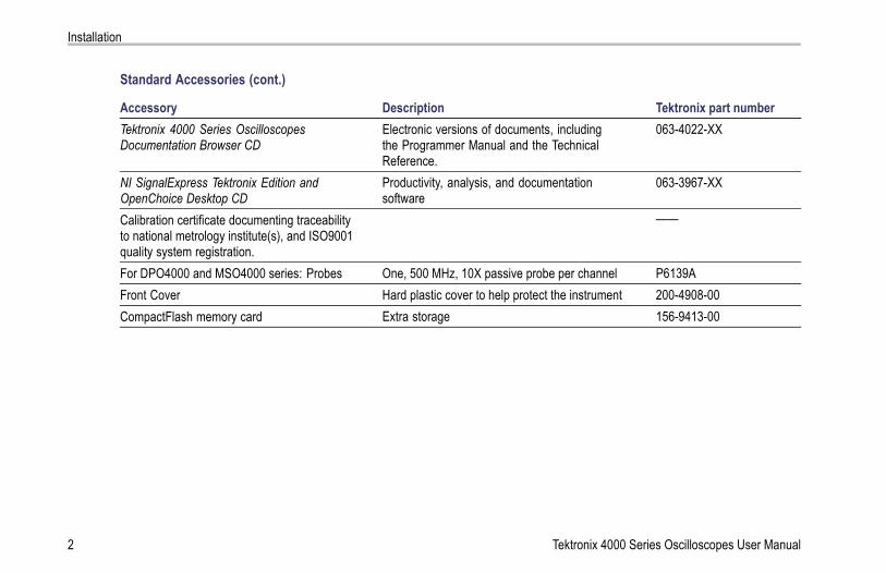
Standard Accessories (cont.)
Accessory Description Tektronix part numberTektronix 4000 Series OscilloscopesDocumentation Browser CD
Electronic versions of documents, includingthe Programmer Manual and the TechnicalReference.
063-4022-XX
NI SignalExpress Tektronix Edition andOpenChoice Desktop CD
Productivity, analysis, and documentationsoftware
063-3967-XX
Calibration certificate documenting traceabilityto national metrology institute(s), and ISO9001quality system registration.
——
For DPO4000 and MSO4000 series: Probes One, 500 MHz, 10X passive probe per channel P6139AFront Cover Hard plastic cover to help protect the instrument 200-4908-00CompactFlash memory card Extra storage 156-9413-00
2 Tektronix 4000 Series Oscilloscopes User Manual

Installation
Standard Accessories (cont.)
Accessory Description Tektronix part numberNorth America (Option A0) 161-0104-00Universal Euro (Option A1) 161-0104-06United Kingdom (Option A2) 161-0104-07Australia (Option A3) 161-0104-05Switzerland (Option A5) 161-0167-00Japan (Option A6) 161-A005-00China (Option A10) 161-0306-00India (Option A11) 161-0400-00
Power Cord
No power cord or AC adapter (Option A99) ——For MSO4000 series: Logic probe One, 16-channel logic probe P6516
Tektronix 4000 Series Oscilloscopes User Manual 3

Installation
Optional Accessories
Accessory Description Tektronix part numberDPO4EMBD The embedded serial triggering and analysis
module enables triggering on packet levelinformation on I2C and SPI serial buses, as wellas digital views of the signal, bus views, busdecoding, search tools, and packet decode tableswith timestamp information
DPO4EMBD
DPO4AUTO The automotive serial triggering and analysismodule enables triggering on packet levelinformation on CAN serial buses, as well asdigital views of the signal, bus views, busdecoding, search tools, and packet decode tableswith timestamp information
DPO4AUTO
DPO4COMP The computer triggering and analysis moduleenables triggering on RS-232, RS-422, RS-485and UART serial buses, search tools, bus views,bus decoding in hex, binary, and ASCII, anddecode tables with timestamp information
DPO4COMP
DPO4VID The extended video module enables triggeringon a variety of standard HDTV signals, as wellas on custom (non-standard) bilevel and trilevelvideo signals with 3 to 4,000 lines.
DPO4VID
4 Tektronix 4000 Series Oscilloscopes User Manual

Installation
Optional Accessories (cont.)
Accessory Description Tektronix part numberNEX-HD2HEADER Adapter that routes the channels from a Mictor
connector to 0.1 inch header pinsNEX-HD2HEADER
TPA-BNC TekVPI to TekProbe II BNC Adapter TPA-BNCTEK-USB-488 Adapter GPIB to USB Adapter TEK-USB-488Getting Started with OpenChoice SolutionsManual with CD
Describes ways to develop host-computersoftware applications that work with youroscilloscope
020-2513-XX
Rackmount kit Adds rackmount brackets RM4000Soft transit case Case for carrying instrument AC4000Hard transit case Traveling case, which requires use of the soft
transit case (AC4000)HCTEK4321
CompactFlash to USB memory card reader Card reader 119-6827-00USB flash drive Extra storage 119-7276-00Tektronix 4000 Series OscilloscopesProgrammer Manual
Describes commands for remote control of theoscilloscope. Available electronically on theDocumentation Browser CD or for download fromwww.tektronix.com/manuals.
071-2133-XX
Tektronix 4000 Series Oscilloscopes User Manual 5

Installation
Optional Accessories (cont.)
Accessory Description Tektronix part numberTektronix 4000 Series Oscilloscopes TechnicalReference Manual
Describes the oscilloscope specifications andperformance verification procedure. Availableelectronically on the Documentation Browser CDor for download from www.tektronix.com/manuals.
071-2132-XX
Tektronix 4000 Series Oscilloscopes Servicemanual
Service information on DPO4000 and MSO4000oscilloscopes
071-2137-XX
Tektronix 4000 Series Oscilloscopes ModuleInstallation Instructions
Manual 071-2136-XX
The DPO4000 and MSO4000 series oscilloscopes work with multiple optional probes. (See page 12, Connecting Probes.) Checkthe Tektronix Web site (www.tektronix.com) for the most current information.
6 Tektronix 4000 Series Oscilloscopes User Manual

Installation
Operating ConsiderationsDPO4000 and MSO4000 SeriesOscilloscopesInput Voltage: 100 V to 240 V ±10%Input Power Frequency:47 Hz to 66 Hz (100 V to 240 V)400 Hz (100 V to 132 V)Power Consumption: 250 W maximumWeight: 5 kg (11 lbs), standalone instrumentHeight, including feet but not handle:229 mm (9.0 in)Width, from handle hub to handle hub: 439 mm (17.3 in)Depth, from feet to front of knobs: 137 mm (5.4 in)Depth, from feet to front of front cover: 145 mm (5.7 in)Clearance: 51 mm (2 in)
DPO4000 series
Tektronix 4000 Series Oscilloscopes User Manual 7

Installation
Temperature:Operating: +0 °C to +50 °CNonoperating: -20 °C to +60 °C
Humidity:Operating: High: 40 °C to 50 °C, 10% to 60% RHOperating: Low: 0 °C to 40 °C, 10 to 90% RHNon-operating: High: 40 °C to 60 °C, 5 to 60% RHNon-operating: Low: 0 °C to 40 °C, 5 to 90% RH
MSO4000 series
Altitude:Operating: 3,000 m (about 10,000 ft)Nonoperating Altitude: 12,192 m (40,000 ft)
Random Vibration:Operating: 0.31 GRMS, 5 – 500 Hz, 10 minutes per axis, 3 axes (30 minutes total)Non-operating: 2.46 GRMS, 5 – 500 Hz, 10 minutes per axis, 3 axes (30 minutes total)
Pollution Degree: 2, Indoor use only
8 Tektronix 4000 Series Oscilloscopes User Manual

Installation
Acquisition System: 1 MΩThe maximum input voltage at the BNC, between center conductor and shield is 400 Vpk (DF ≤ 39.2%), 250 VRMS to 130 kHzderated to 2.6 V RMS at 500 MHz.The maximum transient withstand voltage is ± 800 Vpk.For steady-state sinusoidal waveforms, derate at 20 dB/decade above 200 kHz to 13 Vpk at 3 MHz and above.
Acquisition System: 50 ΩThe maximum input voltage at the BNC, between center conductor and shield is 5 VRMS, with peaks ≤ ±20 V (DF ≤ 6.25%)
Acquisition System: Digital InputsThe maximum input voltage at the input for the logic probe is ±15 V peak.
Aux In: 1 MΩThe maximum input voltage at the BNC, between center conductor and shield is 400 Vpk (DF ≤ 39.2%), 250 VRMS to 2 MHzderated to 5 VRMS at 500 MHz.The maximum transient withstand voltage is ±800 Vpk.For steady-state sinosoidal waveforms, derate at 20 dB/decade above 200 kHz to 13 Vpk at 3 MHz and above.
CAUTION. To ensure proper cooling, keep the sides and rear of the instrument clear of obstructions.
Tektronix 4000 Series Oscilloscopes User Manual 9

Installation
P6139A Passive Probe
Input Voltage:400 VRMS or 400 V DC; CAT I (2,500 Vpk transient)300 VRMS or 300 V DC; CAT II (2,500 Vpk transient150 VRMS or 150 V DC; CAT III (2,500 Vpk transient)For steady-state, sinusoidal waveforms, derate at 20 dB/decade above 2.5 MHz to 50 VRMS at 20 MHz and above.
Output Voltage (terminated into 1 MΩ):40 VRMS or 40 V DC; CAT I (2,500 Vpk impulse)30 VRMS or 30 V DC; CAT I (250 Vpk impulse)15 VRMS or 15 V DC; CAT I (250 Vpk impulse)
Temperature:Operating: -15 °C to +65 °C ( +5 °F to +149 °F)Nonoperating: -62 °C to +85 °C ( -80 °F to +185 °F)
Altitude: ≤ 2,000 meters
Pollution Degree: 2, Indoor use only
Humidity:Operating: High: 40 °C to 50 °C, 10% to 60% RHOperating: Low: 0 °C to 40 °C, 10 to 90% RH
10 Tektronix 4000 Series Oscilloscopes User Manual

Installation
P6516 Digital Probe
Threshold Accuracy: ±(100 mV + 3% of threshold)
Maximum signal swing: 6.0 Vpeak-to-peak centered around the threshold voltage
Minimum signal swing: 500 mVpeak-to-peak
Input resistance: 20 KΩ
Input capacitance: 3.0 pF typical
Temperature:Operating: 0 °C to +50 °C (+32 °F to +122 °F)Nonoperating: -55 °C to +75 °C (-67 °F to +167 °F)
Altitude:Operating: 4.5 km (15,000 ft) maximumNonoperating: 15 km (50,000 ft) maximum
Pollution Degree: 2, Indoor use only
Tektronix 4000 Series Oscilloscopes User Manual 11

Installation
Humidity:10% to 95% relative humidity
CleaningInspect the oscilloscope and probes as often as operating conditions require. To clean the exterior surface, perform the followingsteps:
1. Remove loose dust on the outside of the oscilloscope and probes with a lint-free cloth. Use care to avoid scratching the clearglass display filter.
2. Use a soft cloth dampened with water to clean the oscilloscope. Use an aqueous solution of 75% isopropyl alcohol formore efficient cleaning.
CAUTION. To avoid damage to the surface of the oscilloscope or probes, do not use any abrasive or chemical cleaning agents.
Connecting ProbesThe oscilloscope supports probes with the following:
12 Tektronix 4000 Series Oscilloscopes User Manual

Installation
1. Tektronix Versatile Probe Interface(TekVPI)These probes support two-waycommunication with the oscilloscopethrough on-screen menus and remotelythrough programmable support. Theremote control is useful in applications likeATE where you want the system to presetprobe parameters.
2. TPA-BNC AdapterThe TPA-BNC Adapter allows you to useTEKPROBE II probe capabilities, such asproviding probe power, and passing scalingand unit information to the oscilloscope.
Tektronix 4000 Series Oscilloscopes User Manual 13

Installation
3. Plain BNC InterfacesSome of these use TEKPROBE capabilitiesto pass the waveform signal and scalingto the oscilloscope. Some only pass thesignal and there is no other communication.
4. Digital Probe Interface (MSO4000 seriesonly)The P6516 probe provides 16 channels ofdigital (on or off state) information.
14 Tektronix 4000 Series Oscilloscopes User Manual

Installation
For more information on the many probes available for use with DPO4000 and MSO4000 series oscilloscopes, refer towww.tektronix.com.
Securing the Oscilloscope1. Use a standard laptop computer security
lock to secure your oscilloscope to yourlocation.
Tektronix 4000 Series Oscilloscopes User Manual 15

Installation
Powering On the OscilloscopeGround the Oscilloscope and YourselfBefore pushing the power switch, connect the oscilloscope to an electrically neutral reference point, such as earth ground. Do thisby plugging the three-pronged power cord into an outlet grounded to earth ground.
Grounding the oscilloscope is necessary for safety and to take accurate measurements. The oscilloscope needs to share thesame ground as any circuits that you are testing.
If you are working with static sensitivecomponents, ground yourself. Static electricitythat builds up on your body can damagestatic-sensitive components. Wearing agrounding strap safely sends static charges onyour body to earth ground.
16 Tektronix 4000 Series Oscilloscopes User Manual

Installation
To connect the power cord and power on the oscilloscope:
Tektronix 4000 Series Oscilloscopes User Manual 17

Installation
Powering Off the OscilloscopeTo power off the oscilloscope and remove the power cord:
18 Tektronix 4000 Series Oscilloscopes User Manual

Installation
Functional CheckPerform this quick functional check to verify that your oscilloscope is operating correctly.
1. Connect the oscilloscope power cable asdescribed in Powering On the Oscilloscope.(See page 16.)
2. Power on the oscilloscope.
Tektronix 4000 Series Oscilloscopes User Manual 19

Installation
3. Connect the P6139A probe tip andreference lead to the PROBE COMPconnectors on the oscilloscope.
4. Push Default Setup.
20 Tektronix 4000 Series Oscilloscopes User Manual

Installation
5. Push Autoset. The screen should nowdisplay a square wave, approximately2.5 V at 1 kHz.
NOTE. For best performance, it isrecommended that you set the Vertical scaleto 500 mV.
If the signal appears but is misshapen,perform the procedures for compensatingthe probe. (See page 22, Compensating aPassive Voltage Probe.)If no signal appears, rerun the procedure.If this does not remedy the situation, havethe instrument serviced by qualified servicepersonnel.
Tektronix 4000 Series Oscilloscopes User Manual 21

Installation
Compensating a Passive Voltage ProbeWhenever you attach a passive voltage probe for the first time to any input channel, compensate the probe to match it tothe corresponding oscilloscope input channel.
To properly compensate your passive probe:
1. Follow the steps for the functionalcheck. (See page 19, FunctionalCheck.)
2. Check the shape of the displayedwaveform to determine if your probeis properly compensated. Properly compensated Under compensated Over compensated
22 Tektronix 4000 Series Oscilloscopes User Manual

Installation
3. If necessary, adjust your probe.Repeat as needed.
Tektronix 4000 Series Oscilloscopes User Manual 23

Installation
Quick Tips
Use the shortest possible ground lead andsignal path to minimize probe-induced ringingand distortion on the measured signal.
Signal with a short ground lead Signal with a long ground lead
24 Tektronix 4000 Series Oscilloscopes User Manual

Installation
Application Module Free TrialA 30-day free trial is available for all application modules not installed in your oscilloscope. The trial period begins when you poweron the oscilloscope for the first time.
After 30 days, you must purchase the module if you want to continue using the application. To see the date when your free trialperiod expires, push the front panel Utility button, push the lower-bezel Utility Page button, use multipurpose knob a to selectConfig, and push the lower-bezel Version button.
Installing an Application Module
CAUTION. To avoid damage to the oscilloscope or application module, observe ESD (electrostatic discharge) precautions.(See page 16, Powering On the Oscilloscope.)
Turn off the oscilloscope power while removing or adding an application module.
(See page 18, Powering Off the Oscilloscope.)
Tektronix 4000 Series Oscilloscopes User Manual 25

Installation
Optional application module packages extend the capability of your oscilloscope. You can install up to four application modules atone time. Application modules go into the two slots with windows in the upper right corner of the front panel. Two additional slotsare directly behind the two that you can see. To use these slots, install the module with the label facing away from you.
Refer to the Tektronix 4000 Series Oscilloscopes Application Module Installation Instructions that came with your application modulefor instructions on installing and testing an application module.
NOTE. If you remove an application module, the features provided by the application module become unavailable. To restore thefeatures, turn off the oscilloscope power, reinstall the module and turn on the oscilloscope power.
Changing the User Interface LanguageTo change the language of the oscilloscope user interface, and to change the front-panel button labels through the use of an overlay:
1. Push Utility.
2. Push Utility Page. Utility Page
26 Tektronix 4000 Series Oscilloscopes User Manual
Installation
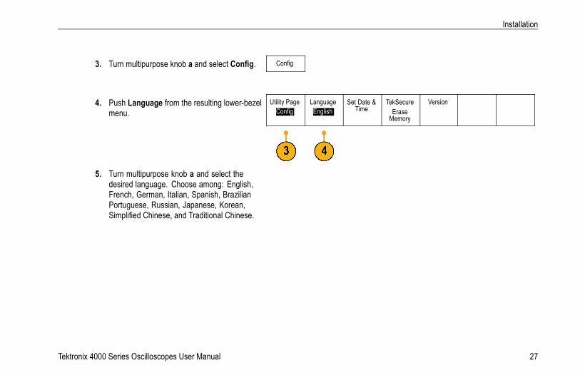
3. Turn multipurpose knob a and select Config. Config
4. Push Language from the resulting lower-bezelmenu.
Utility PageConfig
LanguageEnglish
Set Date &Time
TekSecureErase
Memory
Version
5. Turn multipurpose knob a and select thedesired language. Choose among: English,French, German, Italian, Spanish, BrazilianPortuguese, Russian, Japanese, Korean,Simplified Chinese, and Traditional Chinese.
Tektronix 4000 Series Oscilloscopes User Manual 27
Installation
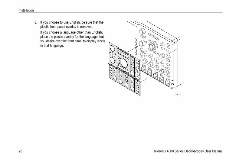
6. If you choose to use English, be sure that theplastic front-panel overlay is removed.If you choose a language other than English,place the plastic overlay for the language thatyou desire over the front panel to display labelsin that language.
28 Tektronix 4000 Series Oscilloscopes User Manual

Installation
Changing the Date and TimeTo set the internal clock with the current date and time:
1. Push Utility.
2. Push Utility Page. Utility Page
3. Turn multipurpose knob a and select Config. Config
4. Push Set Date & Time. SystemConfig
LanguageEnglish
Set Date &Time
TekSecureErase
Memory
Version
Tektronix 4000 Series Oscilloscopes User Manual 29

Installation
Set Date &Time
DisplayDate &Time
On| Off
5. Push the side-bezel buttons and turn bothmultipurpose knobs (a and b) to set the timeand date values.
Hour4
Minute1
MonthMayDay
3
Year2007
6. Push OK Enter Date & Time. OK EnterDate &Time
30 Tektronix 4000 Series Oscilloscopes User Manual

Installation
Signal Path CompensationSignal Path Compensation (SPC) corrects for DC inaccuracies caused by temperature variations and/or long-term drift. Run thecompensation whenever the ambient temperature has changed by more than 10 °C or once a week if you use vertical settings of5 mV/division or less. Failure to do so may result in the instrument not meeting warranted performance levels at those volts/divsettings.
To compensate the signal path:
1. Warm up the oscilloscope for at least20 minutes. Remove all input signals (probesand cables) from channel inputs. Input signalswith AC components adversely affect SPC.
Tektronix 4000 Series Oscilloscopes User Manual 31
Installation
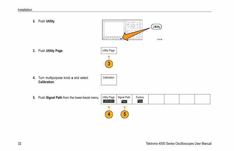
2. Push Utility.
3. Push Utility Page. Utility Page
4. Turn multipurpose knob a and selectCalibration.
Calibration
5. Push Signal Path from the lower-bezel menu. Utility PageCalibration
Signal PathPass
FactoryPass
32 Tektronix 4000 Series Oscilloscopes User Manual

Installation
6. Push OK Compensate Signal Paths fromthe resulting side-bezel menu.
OK Com-pensateSignalPaths
The calibration will take approximately10 minutes to complete.
7. After calibration, verify that the status indicatoron the lower-bezel menu displays Pass.
Utility PageCalibration
Signal PathPass
FactoryPass
If it does not, then recalibrate the instrumentor have the instrument serviced by qualifiedservice personnel.
G
8. Service personnel use the factory calibrationfunctions to calibrate the internal voltagereferences of the oscilloscope using externalsources. Refer to your Tektronix field officeor representative for assistance with factorycalibration.
NOTE. Signal Path Compensation does not include calibration to the probe tip. (See page 22, Compensating a Passive VoltageProbe.)
Tektronix 4000 Series Oscilloscopes User Manual 33

Installation
Upgrading FirmwareTo upgrade the firmware of the oscilloscope:
1. Open up a Web browser and go towww.tektronix.com/software. Proceed to thesoftware finder. Download the latest firmwarefor your oscilloscope on your PC.
Unzip the files and copy the firmware.img fileinto the root folder of a USB flash drive.
34 Tektronix 4000 Series Oscilloscopes User Manual
Installation
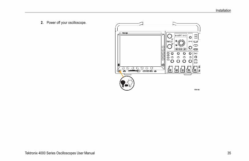
2. Power off your oscilloscope.
Tektronix 4000 Series Oscilloscopes User Manual 35

Installation
3. Insert the USB flash drive into the front-panelUSB port on your oscilloscope.
36 Tektronix 4000 Series Oscilloscopes User Manual

Installation
4. Power on the oscilloscope. The instrumentautomatically recognizes the replacementfirmware and installs it.If the instrument does not install the firmware,rerun the procedure. If the problem continues,contact qualified service personnel.
NOTE. Do not power off the oscilloscope orremove the USB flash drive until the oscilloscopefinishes installing the firmware.
Tektronix 4000 Series Oscilloscopes User Manual 37

Installation
5. Power off the oscilloscope and remove theUSB flash drive.
38 Tektronix 4000 Series Oscilloscopes User Manual

Installation
6. Power on the oscilloscope.
7. Push Utility.
Tektronix 4000 Series Oscilloscopes User Manual 39

Installation
8. Push Utility Page. Utility Page
9. Turn multipurpose knob a and select Config. Config
10. Push Version. The oscilloscope displays thefirmware version number.
Utility PageConfig
LanguageEnglish
Set Date &Time
TekSecureErase
Memory
Version
11. Confirm that the version number matches thatof the new firmware.
40 Tektronix 4000 Series Oscilloscopes User Manual

Installation
Connecting Your Oscilloscope to a ComputerYou may want to document your work for future reference. Instead of saving screen images and waveform data to a CompactFlashstorage device or USB flash drive, and then generating a report later, you may want to send the image or waveform data directly toa remote PC for analysis. You may also want to control an oscilloscope at a remote location from your computer. (See page 218,Saving a Screen Image.) (See page 220, Saving and Recalling Waveform Data.)
Two ways to connect your oscilloscope to a computer are through the VISA drivers and the e*Scope Web-enabled tools. UseVISA to communicate with your oscilloscope from your computer through a software application. Use e*Scope to communicatewith your oscilloscope through a Web browser.
Using VISAVISA lets you use your MS-Windows computer to acquire data from your oscilloscope for use in an analysis package that runs onyour PC, such as Microsoft Excel, National Instruments LabVIEW, or a program of your own creation. You can use a commoncommunications connection, such as USB, Ethernet, or GPIB, to connect the computer to the oscilloscope.
To set up VISA communications between your oscilloscope and a computer:
1. Load the VISA drivers on your computer.You will find the drivers on the appropriateCD that comes with your oscilloscope orat the Tektronix software finder Web page(www.tektronix.com).
Tektronix 4000 Series Oscilloscopes User Manual 41

Installation
2. Connect the oscilloscope to your computerwith the appropriate USB or Ethernet cable.
To communicate between the oscilloscope anda GPIB system, connect the oscilloscope tothe TEK-USB-488 GPIB-to-USB Adapter witha USB cable. Then connect the adapter toyour GPIB system with a GPIB cable.
42 Tektronix 4000 Series Oscilloscopes User Manual

Installation
3. Push Utility.
4. Push Utility Page. Utility Page
5. Turn multipurpose knob a and select I/O. I/O
6. If you are using USB, the system sets itself upautomatically for you, if USB is enabled.
Utility PageI/O
USBEnabled
EthernetNetworkSettings
GPIB1
Check USB on the lower-bezel menu to besure that USB is enabled. If it is not enabled,push USB. Then push Enabled on theside-bezel menu.
Tektronix 4000 Series Oscilloscopes User Manual 43
Installation
ChangeInstrument
Settings
DHCP/BOOTP
On| Off
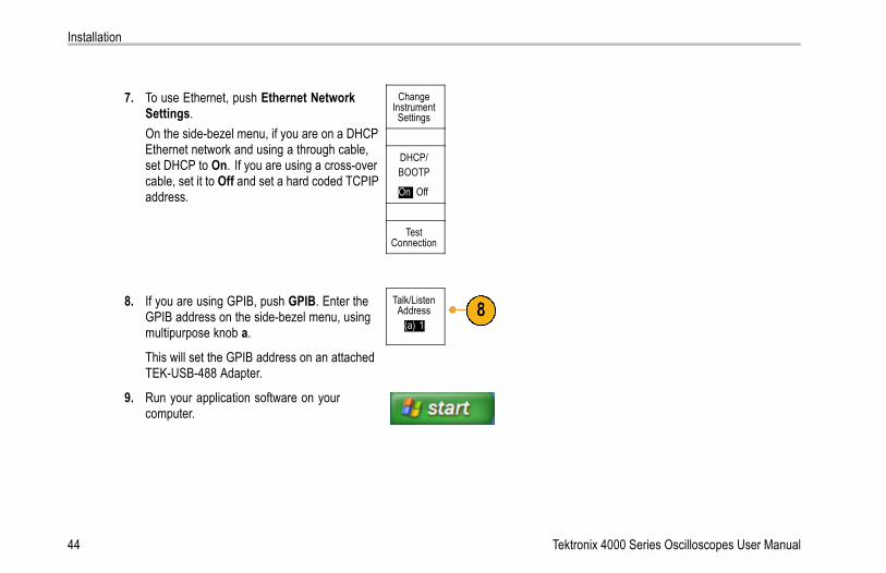
7. To use Ethernet, push Ethernet NetworkSettings.On the side-bezel menu, if you are on a DHCPEthernet network and using a through cable,set DHCP to On. If you are using a cross-overcable, set it to Off and set a hard coded TCPIPaddress.
TestConnection
8. If you are using GPIB, push GPIB. Enter theGPIB address on the side-bezel menu, usingmultipurpose knob a.
Talk/ListenAddress
(a) 1
This will set the GPIB address on an attachedTEK-USB-488 Adapter.
9. Run your application software on yourcomputer.
44 Tektronix 4000 Series Oscilloscopes User Manual

Installation
Quick TipsThe CD that is shipped with your oscilloscope includes a variety of Windows-based software tools designed to ensure efficientconnectivity between your oscilloscope and your computer. There are toolbars that speed connectivity with Microsoft Excel andWord. There is also a standalone acquisition program called the OpenChoice Desktop.
The rear-panel USB 2.0 device port is the correct USB port for computer connectivity. Use the rear- and front-panel USB 2.0host ports to connect your oscilloscope to USB flash drives and printers.
USB Host port
USB Device port
Tektronix 4000 Series Oscilloscopes User Manual 45
Installation
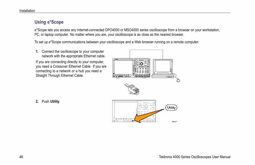
Using e*Scopee*Scope lets you access any Internet-connected DPO4000 or MSO4000 series oscilloscope from a browser on your workstation,PC, or laptop computer. No matter where you are, your oscilloscope is as close as the nearest browser.
To set up e*Scope communications between your oscilloscope and a Web browser running on a remote computer:
1. Connect the oscilloscope to your computernetwork with the appropriate Ethernet cable.
If you are connecting directly to your computer,you need a Crossover Ethernet Cable. If you areconnecting to a network or a hub you need aStraight Through Ethernet Cable.
2. Push Utility.
46 Tektronix 4000 Series Oscilloscopes User Manual

Installation
3. Push Utility Page. Utility Page
4. Turn multipurpose knob a and select I/O. I/O
5. Push Ethernet Network Settings. Utility PageI/O
USBEnabled
EthernetNetworkSettings
GPIB1
Tektronix 4000 Series Oscilloscopes User Manual 47

Installation
6. On the side-bezel menu, if you are on aDHCP Ethernet network and using dynamicaddressing, set DHCP to On. If you are usingstatic addressing, set it to Off.
ChangeInstrument
Settings
Push Change Instrument Settings. If youare using DHCP, note the Ethernet addressand instrument name. If you are using Staticaddressing, enter the Ethernet address youwill be using.
DHCP/BOOTP
On| Off
TestConnection
NOTE. Depending on the type and speed ofnetwork to which your 4000 series oscilloscope isconnected, you may not see the DHCP/BOOTPfield update instantaneously after pressing theDHCP/BOOTP button. It may take a few secondsto update.
48 Tektronix 4000 Series Oscilloscopes User Manual

Installation
7. Start your browser on your remote computer.In the browser address line, enter the IPaddress or, if DHCP is set to On in theoscilloscope, simply enter the instrumentname.
8. You should now see the e*Scope screenshowing the oscilloscope display, on your Webbrowser.If e*Scope does not work, rerun the procedure.If it still does not work, contact qualified servicepersonnel.
Connecting a USB Keyboard to Your OscilloscopeYou can connect a USB keyboard to a USB Host port on the rear or front panel of the oscilloscope. The oscilloscope will detect thekeyboard, even if it is plugged in while the oscilloscope is powered on.
You can use the keyboard to quickly create names or labels. You can bring up the Label menu through the lower-bezel label buttonof the Channel or Bus menus. Use the arrow keys on the keyboard to move the insertion point, and then type in a name or label.Labeling channels and buses makes the information on the screen easier to identify.
Tektronix 4000 Series Oscilloscopes User Manual 49

Installation
50 Tektronix 4000 Series Oscilloscopes User Manual

Get Acquainted with the Instrument
Get Acquainted with the InstrumentFront-Panel Menus and Controls
The front panel has buttons and controls for the functions that you use most often. Use the menu buttons to access morespecialized functions.
Tektronix 4000 Series Oscilloscopes User Manual 51

Get Acquainted with the Instrument
Using the Menu System
To use the menu system:
1. Push a front-panel menu button to displaythe menu that you want to use.You can use the B1 through B4 buttonson the MSO4000 series oscilloscopes tosupport up to four different serial or parallelbuses.
52 Tektronix 4000 Series Oscilloscopes User Manual

Get Acquainted with the Instrument
2. Push a lower-bezel button to select amenu item. If a pop-up menu appears, turnmultipurpose knob a to select the desiredchoice.
3. Push a side-bezel button to choose aside-bezel menu item.If the menu item contains more thanone choice, push the side-bezel buttonrepeatedly to cycle through the choices.If a pop-up menu appears, turnmultipurpose knob a to select the desiredchoice.
Tektronix 4000 Series Oscilloscopes User Manual 53

Get Acquainted with the Instrument
4. To remove a side-bezel menu, push thelower-bezel button again or push MenuOff.
5. Certain menu choices require you to set anumeric value to complete the setup. Usethe upper and lower multipurpose knobs aand b to adjust values.
6. Push Fine to turn off or on the ability tomake smaller adjustments.
54 Tektronix 4000 Series Oscilloscopes User Manual

Get Acquainted with the Instrument
Using the Menu ButtonsUse the menu buttons to perform many functions in the oscilloscope.
1. Measure. Push to perform automatedmeasurements on waveforms or toconfigure cursors.
2. Search. Push to search through anacquisition for user-defined events/criteria.
3. Test. Push to activate advanced orapplication-specific testing features.
4. Acquire. Push to set the acquisition modeand adjust the record length.
5. Autoset. Push to perform an automaticsetup of oscilloscope settings.
6. Trigger Menu. Push to specify triggersettings.
Tektronix 4000 Series Oscilloscopes User Manual 55

Get Acquainted with the Instrument
7. Utility. Push to activate the system utilityfunctions, such as selecting a language orsetting the date/time.
8. Save / Recall Menu. Push to saveand recall setups, waveforms, andscreen images to internal memory, aCompactFlash card, or a USB flash drive.
9. Channel 1,2,3, or 4 Menu. Push to setvertical parameters for input waveformsand to display or remove the correspondingwaveform from the display.
56 Tektronix 4000 Series Oscilloscopes User Manual

Get Acquainted with the Instrument
10. B1 or B2. Push to define and display abus if you have the appropriate moduleapplication keys. The DPO4AUTO modulesupports CAN. The DPO4EMBD modulesupports I2C and SPI. The DPO4COMPmodule supports RS-232.Also, push the B1 or B2 button to displayor remove the corresponding bus from thedisplay.On the MSO4000 series, you can use theB3 and B4 buttons to support up to fourdifferent serial buses, and parallel buses.
11. R. Push to manage reference waveforms,including the display or removal of eachreference waveform from the display.
12. M. Push to manage the math waveform,including the display or removal of themath waveform from the display.
Tektronix 4000 Series Oscilloscopes User Manual 57

Get Acquainted with the Instrument
Using Other ControlsThese buttons and knobs control waveforms, cursors, and other data input.
1. Turn the upper multipurpose knob a,when activated, to move a cursor, to set anumerical parameter value for a menu item,or to select from a pop-up list of choices.Push the nearby Fine button to togglebetween coarse and fine adjustment.Screen icons tell you when a or b areactive.
2. Cursors. Push once to activate the twovertical cursors. Push again to turn on thetwo vertical and two horizontal cursors.Push again to turn off all cursors.When the cursors are on, you can turnthe multipurpose knobs to control theirposition.
58 Tektronix 4000 Series Oscilloscopes User Manual

Get Acquainted with the Instrument
3. Select. Push to activate special functions.For example, when using the two verticalcursors (and no horizontal ones arevisible), you can push this button to link orunlink the cursors. When the two verticaland two horizontal cursors are both visible,you can push this button to make either thevertical cursors or the horizontal cursorsactive.
4. Fine. Push to toggle between makingcoarse and fine adjustments with thevertical and horizontal position knobs, thetrigger level knob, and many operations ofmultipurpose knobs a and b.
5. Waveform Intensity. Push to enablemultipurpose knob a to control waveformdisplay intensity and knob b to controlgraticule intensity.
Tektronix 4000 Series Oscilloscopes User Manual 59

Get Acquainted with the Instrument
6. Turn the lower multipurpose knob b,when activated, to move a cursor or seta numerical parameter value for a menuitem. Push Fine to make adjustmentsmore slowly.
7. Zoom button. Push to activate zoommode.
8. Pan (outer knob). Turn to scroll the zoomwindow through the acquired waveform.
9. Zoom (inner knob). Turn to control thezoom factor. Turning it clockwise zooms infurther. Turning it counterclockwise zoomsout.
10. Play-pause button. Push to start or stopthe automatic panning of a waveform.Control the speed and direction with thepan knob.
11. ← Prev. Push to jump to the previouswaveform mark.
60 Tektronix 4000 Series Oscilloscopes User Manual

Get Acquainted with the Instrument
12. Set/Clear Mark. Push to establish ordelete a waveform mark.
13. → Next. Push to jump to the nextwaveform mark.
14. Horizontal Position. Turn to adjustthe trigger point location relative to theacquired waveforms. Push Fine to makesmaller adjustments.
15. Horizontal Scale. Turn to adjust thehorizontal scale (time/division).
Tektronix 4000 Series Oscilloscopes User Manual 61
Get Acquainted with the Instrument
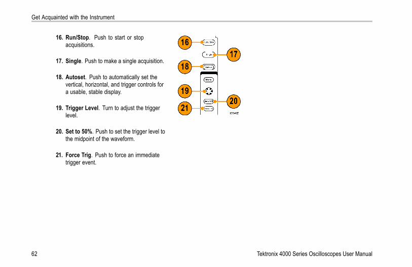
16. Run/Stop. Push to start or stopacquisitions.
17. Single. Push to make a single acquisition.
18. Autoset. Push to automatically set thevertical, horizontal, and trigger controls fora usable, stable display.
19. Trigger Level. Turn to adjust the triggerlevel.
20. Set to 50%. Push to set the trigger level tothe midpoint of the waveform.
21. Force Trig. Push to force an immediatetrigger event.
62 Tektronix 4000 Series Oscilloscopes User Manual

Get Acquainted with the Instrument
22. Vertical Position. Turn to adjust thevertical position of the correspondingwaveform. Push Fine to make smalleradjustments.
23. 1, 2, 3, 4. Push to display or remove thecorresponding waveform from the displayand access the vertical menu.
24. Vertical Scale. Turn to adjust the verticalscale factor of the corresponding waveform(volts/division).
25. Print. Push to print a screen image usingthe printer selected in the Utility menu.
26. Power switch. Push to power on or off theinstrument.
Tektronix 4000 Series Oscilloscopes User Manual 63

Get Acquainted with the Instrument
27. USB 2.0 host port. Insert a USBcable here to connect peripherals to theoscilloscope, such as a keyboard, a printer,or a flash drive. There are two more USB2.0 host ports on the rear panel.
28. CompactFlash Drive. Insert aCompactFlash card here.
29. CompactFlash Eject. Pops theCompactFlash card out of theCompactFlash drive.
30. Save. Push to perform an immediate saveoperation. The save operation uses thecurrent save parameters, as defined in theSave / Recall menu.
31. Default Setup. Push to perform animmediate restore of the oscilloscope tothe default settings.
64 Tektronix 4000 Series Oscilloscopes User Manual
Get Acquainted with the Instrument
32. D15 - D0. Push to display or remove thedigital channels from the display, and toaccess the digital channel setup menu(MSO4000 series only).
33. Menu Off. Push to clear a displayed menufrom the screen.
Tektronix 4000 Series Oscilloscopes User Manual 65

Get Acquainted with the Instrument
Identifying Items in the Display
The items shown to the right may appear in thedisplay. Not all of these items are visible at anygiven time. Some readouts move outside thegraticule area when menus are turned off.
66 Tektronix 4000 Series Oscilloscopes User Manual

Get Acquainted with the Instrument
1. The acquisition readout shows when anacquisition is running, stopped, or whenacquisition preview is in effect. Icons are:
Run: Acquisitions enabled
Stop: Acquisitions not enabled
Roll: In roll mode (40 ms/div or slower)
PreVu: In this state, the oscilloscopeis stopped or between triggers. Youcan change the horizontal or verticalposition or scale to see approximatelywhat the next acquisition will look like.
Tektronix 4000 Series Oscilloscopes User Manual 67

Get Acquainted with the Instrument
2. The trigger position icon shows the triggerposition in the acquisition.
3. The expansion point icon (an orangetriangle) shows the point that the horizontalscale expands and compresses around.
4. The waveform record view shows thetrigger location relative to the waveformrecord. The line color corresponds to theselected waveform color.
68 Tektronix 4000 Series Oscilloscopes User Manual

Get Acquainted with the Instrument
5. The trigger status readout shows triggerstatus. Status conditions are:
Trig’d: Triggered
Auto: Acquiring untriggered data
PrTrig: Acquiring pretrigger data
Trig?: Waiting for trigger
6. The cursor readout shows time, amplitude,and delta (Δ) values for each cursor.For FFT measurements, it shows frequencyand magnitude.For serial buses, the readout shows thedecoded values.
Tektronix 4000 Series Oscilloscopes User Manual 69

Get Acquainted with the Instrument
7. The trigger level icon shows the triggerlevel on the waveform. The icon colorcorresponds to the trigger source color.
8. The trigger readout shows the triggersource, slope, and level. The triggerreadouts for other trigger types show otherparameters.
9. The top line of the record length/samplingrate readout shows the sampling rate(adjust with the Horizontal Scale knob).The bottom line shows the record length(adjust with the Acquire menu).
70 Tektronix 4000 Series Oscilloscopes User Manual

Get Acquainted with the Instrument
10. The horizontal position/scale readoutshows on the top line the horizontal scale(adjust with the Horizontal Scale knob)and on the bottom line the time from the Tsymbol to the expansion point icon (adjustwith the Horizontal Position knob).Use horizontal position to insert addeddelay between when the trigger occurs andwhen you actually capture the data. Inserta negative time to capture more pretriggerinformation.
11. The Timing Resolution readout shows thetiming resolution of the digital channels.Timing resolution is the time betweensamples. It is the reciprocal of the digitalsample rate.When the MagniVu control is on, “MagniVu”appears in the readout.
Tektronix 4000 Series Oscilloscopes User Manual 71

Get Acquainted with the Instrument
12. Measurement readouts show the selectedmeasurements. You can select up to fourmeasurements to display at one time.A symbol appears instead of theexpected numerical measurement if avertical clipping condition exists. Part of thewaveform is above or below the display. Toobtain a proper numerical measurement,turn the vertical scale and position knobsto make all of the waveform appear in thedisplay.
13. The auxiliary waveform readouts show thevertical and horizontal scale factors of themath or reference waveforms.
14. The channel readout shows the channelscale factor (per division), coupling, invert,and bandwidth status. Adjust with theVertical Scale knob and the channel 1, 2,3, or 4 menus.
72 Tektronix 4000 Series Oscilloscopes User Manual

Get Acquainted with the Instrument
15. For analog channels, the waveformbaseline indicator shows the zero-voltlevel of a waveform (ignoring the effect ofoffset). The icon colors correspond to thewaveform colors.
16. For digital channels (MSO4000 seriesonly), the baseline indicators point to thehigh and low levels. The indicator colorsfollow the color code used on resistors.The D0 indicator is black, the D1 indicatoris brown, the D2 indicator is red, and so on.
Tektronix 4000 Series Oscilloscopes User Manual 73

Get Acquainted with the Instrument
17. The group icon indicates when digitalchannels are grouped (MSO4000 seriesonly).
18. The bus display shows decoded packetlevel information for serial buses or forparallel buses (MSO4000 series only). Thebus indicator shows the bus number andbus type.
74 Tektronix 4000 Series Oscilloscopes User Manual

Get Acquainted with the Instrument
Front-Panel Connectors1. Logic Probe Connector
2. Channel 1, 2, (3, 4). Channel inputs withTekVPI Versatile Probe Interface.
3. Aux In. Trigger level range is adjustablefrom +8 V to –8 V. The maximum inputvoltage is 400V peak, 250V RMS. Inputresistance is 1 MΩ ± 1% in parallel with13 pF ±2 pF.
4. PROBE COMP. Square wave signalsource to compensate probes. Outputvoltage: 0 – 2.5V, amplitude ± 1% behind1 kΩ ±2%. Frequency: 1 kHz.
5. Ground.
6. Application Module Slots.
Tektronix 4000 Series Oscilloscopes User Manual 75
Get Acquainted with the Instrument
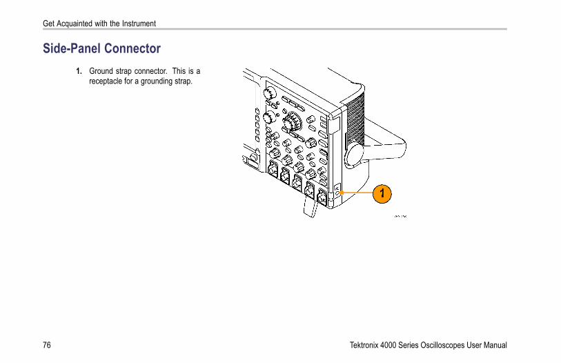
Side-Panel Connector1. Ground strap connector. This is a
receptacle for a grounding strap.
76 Tektronix 4000 Series Oscilloscopes User Manual

Get Acquainted with the Instrument
Rear-Panel Connectors1. Trigger Out. Use the trigger signal output
to synchronize other test equipmentwith your oscilloscope. A LOW toHIGH transition indicates that the triggeroccurred. The logic level for Vout (HI) is≥2.5V open circuit; ≥1.0 V into a 50Ω loadto ground. The logic level for Vout (LO) is≤0.7 V into a load of ≤4 mA; ≤0.25 V into a50Ω load to ground.
2. XGA Out. Use the XGA Video port (DB-15female connector) to show the oscilloscopedisplay on an external monitor or projector.
3. LAN. Use the LAN (Ethernet) port (RJ-45connector) to connect the oscilloscope to a10/100 Base-T local area network.
Tektronix 4000 Series Oscilloscopes User Manual 77

Get Acquainted with the Instrument
4. Device. Use the USB 2.0 High speeddevice port to control the oscilloscopethrough USBTMC or GPIB with aTEK-USB-488 Adapter. The USBTMCprotocol allows USB devices tocommunicate using IEEE488 stylemessages. This lets you run your GPIBsoftware applications on USB hardware.
5. Host. Use the USB 2.0 Full speed hostports (three) to take advantage of USBflash drives and printers.
6. Power input. Attach to an AC power linewith integral safety ground. (See page 7,Operating Considerations.)
7. Connector for future use.
78 Tektronix 4000 Series Oscilloscopes User Manual

Acquire the Signal
Acquire the SignalThis section describes concepts of and procedures for setting up the oscilloscope to acquire the signal as you want it to.
Setting Up Analog ChannelsUse front-panel buttons and knobs to set up your instrument to acquire signals using the analog channels.
1. Connect the P6139A or VPI probe to theinput signal source.
Tektronix 4000 Series Oscilloscopes User Manual 79

Acquire the Signal
2. Select the input channel by pushing thefront-panel buttons.
NOTE. If you are using a probe that does notsupply probe encoding, set the attenuation(probe factor) on the oscilloscope vertical menufor the channel to match the probe.
3. Push Default Setup.
4. Push Autoset.
80 Tektronix 4000 Series Oscilloscopes User Manual

Acquire the Signal
5. Push the desired channel button. Thenadjust the vertical position and scale.
6. Adjust the horizontal position and scale.The horizontal position determines thenumber of pretrigger and posttriggersamples.The horizontal scale determines the sizeof the acquisition window relative to thewaveform. You can scale the window tocontain a waveform edge, a cycle, severalcycles, or thousands of cycles.
Tektronix 4000 Series Oscilloscopes User Manual 81

Acquire the Signal
Quick TipUse the zoom feature to see multiple cycles of your signal in the upper part, and a single cycle in the lower part of the display.(See page 203, Using Wave Inspector to Manage Long Record Length Waveforms.)
Labeling Channels and BusesYou can add a label to the channels and buses shown on the display for easy identification. The label is placed on the waveformbaseline indicator in the left side of the screen. The label can have up to 32 characters.
To label a channel, push a channel input button for an analog channel to label a channel.
1. Push a front panel button for an input channelor a bus.
82 Tektronix 4000 Series Oscilloscopes User Manual

Acquire the Signal
2. Push a lower-bezel button to create a label,such as for channel 1 or B1.
Label
3. Push Select Preset Label to view a list oflabels.
SelectPresetLabel
4. Turn multipurpose knob b to scroll through thelist to find a suitable label. You can edit thelabel after you insert it if necessary.
5. Push Insert Preset Label to add the label. InsertPresetLabel
Tektronix 4000 Series Oscilloscopes User Manual 83

Acquire the Signal
If you are using a USB keyboard, use thearrow keys to position the insertion point andedit the inserted label, or type in a new label.(See page 49, Connecting a USB Keyboardto Your Oscilloscope.)
6. If you do not have a USB keyboard connected,push the side- and lower-bezel arrow keys toposition the insertion point.
84 Tektronix 4000 Series Oscilloscopes User Manual

Acquire the Signal
7. Turn multipurpose knob a to scroll through thelist of letters, numbers, and other characters tofind the character in the name that you wantto enter.
ABCDEFGHIJKLMNOPQRSTUVWXYZabcdefghijklmnopqrstuvwxyz0123456789_=+-!@#$%^&*()[]<>/~’”\|:,.?
8. Push Select or Enter Character to let theoscilloscope know that you have picked theproper character to use.
You can use the lower-bezel buttons to editthe label as needed.
EnterCharacter
BackSpace
Delete Clear
Tektronix 4000 Series Oscilloscopes User Manual 85

Acquire the Signal
9. Continue scrolling and pushing Select untilyou have entered all the desired characters.For another label, push the side- andlower-bezel arrow keys to reposition theinsertion point.
10. Push Display Labels and select On to seethe label.
DisplayLabels
On| Off
Using the Default SetupTo return the oscilloscope to its default settings:
1. Push Default Setup.
86 Tektronix 4000 Series Oscilloscopes User Manual

Acquire the Signal
2. If you change your mind, push Undo DefaultSetup to undo the last default setup.
UndoDefaultSetup
Using AutosetAutoset adjusts the instrument (acquisition, horizontal, trigger, and vertical controls) such that it displays four or five waveformcycles for analog channels with the trigger near the midlevel, and ten cycles for digital channels.
Autoset works with both the analog and digital channels.
1. Connect the analog probe, and then selectthe input channel. (See page 79, Setting UpAnalog Channels.)
Connect the digital probe and select theinput channel. (See page 110, Setting UpDigital Channels.)
Tektronix 4000 Series Oscilloscopes User Manual 87

Acquire the Signal
2. Push Autoset to execute an Autoset.
3. If desired, push Undo Autoset to undo thelast Autoset.
UndoAutoset
Quick TipsTo position the waveform appropriately, Autoset may change the vertical position. Autoset always sets vertical offset to 0 V.
If you use Autoset when no channels are displayed, the instrument turns on channel one (1) and scales it.
If you use Autoset and the oscilloscope detects a video signal, the oscilloscope automatically sets the trigger type to video andmakes other adjustments to display a stable video signal.
88 Tektronix 4000 Series Oscilloscopes User Manual

Acquire the Signal
Acquisition ConceptsBefore a signal can be displayed, it must pass through the input channel where it is scaled and digitized. Each channel has adedicated input amplifier and digitizer. Each channel produces a stream of digital data from which the instrument extracts waveformrecords.
Sampling Process
Acquisition is the process of sampling ananalog signal, converting it into digital data,and assembling it into a waveform record,which is then stored in acquisition memory.
Input signal Sampled pointsDigital values
Tektronix 4000 Series Oscilloscopes User Manual 89

Acquire the Signal
Real-Time Sampling
Record pointsDPO4000 and MSO4000 series oscilloscopesuse real-time sampling. In real-time sampling,the instrument digitizes all of the points itacquires using a single trigger event.
Sampling rate
90 Tektronix 4000 Series Oscilloscopes User Manual

Acquire the Signal
Waveform RecordThe instrument builds the waveform record through use of the following parameters:
Sample interval: The time betweenrecorded sample points. Adjust this byturning the Horizontal Scale knob orchanging the record length with the bezelbuttons.
Record length: The number of samplesrequired to fill a waveform record. Set thisby pushing the Acquire button and usingthe resulting lower- and side-bezel menus.
Trigger point: The zero time reference in awaveform record. It is shown on the screenby an orange T.
Tektronix 4000 Series Oscilloscopes User Manual 91

Acquire the Signal
Horizontal position: The time from thetrigger point to the expansion point. Adjustthis by turning the Horizontal Positionknob.Use a positive time to acquire the recordafter the trigger point. Use a negative timeto acquire it before the trigger point.
Expansion point: The point that thehorizontal scale expands and contractsaround. It is shown by an orange triangle.
How the Analog Acquisition Modes WorkSample mode retains the first sampled pointfrom each acquisition interval. Sample is thedefault mode.
92 Tektronix 4000 Series Oscilloscopes User Manual

Acquire the Signal
Peak Detect mode uses the highest and lowestof all the samples contained in two consecutiveacquisition intervals. This mode only workswith real-time, noninterpolated sampling and isuseful for catching high frequency glitches.
Hi Res mode calculates the average of allthe samples for each acquisition interval.This mode also only works with real-time,noninterpolated sampling. Hi-Res provides ahigher-resolution, lower-bandwidth waveform.
Envelope mode finds the highest andlowest record points over all acquisitions.Envelope uses Peak Detect for each individualacquisition.
Average mode calculates the average value foreach record point over a user-specified numberof acquisitions. Average uses Sample mode foreach individual acquisition. Use average modeto reduce random noise.
Tektronix 4000 Series Oscilloscopes User Manual 93

Acquire the Signal
Changing the Acquisition Mode and Record LengthUse this procedure to change the acquisition mode.
1. Push Acquire.
2. Push Mode. ModeSample
RecordLength
10k
ResetHorizontalPosition
WaveformDisplay
XY DisplayOff
94 Tektronix 4000 Series Oscilloscopes User Manual

Acquire the Signal
AcquisitionMode
Sample
PeakDetect
Hi Res
Envelope
3. Then choose the acquisition mode fromthe side-bezel menu. You can chose from:Sample, Peak Detect, Hi Res, Envelope, orAverage.
NOTE. Peak Detect and Hi Res modes takeadvantage of sample points that the oscilloscopewould have discarded at lower sweep speeds.Therefore, these modes only work when thecurrent sample rate is less than the maximumpossible sample rate. As soon as the oscilloscopestarts to acquire at the maximum sample rate, thenthe Peak Detect, Hi Res and Sample modes alllook the same. You can control the sample rate bysetting the Horizontal scale and the Record Length.
Average16
Tektronix 4000 Series Oscilloscopes User Manual 95

Acquire the Signal
4. If you chose Average, turn multipurpose knoba to set the number of waveforms to averageover.
5. Push Record Length.
6. Push the side-bezel menu, record lengthbutton.
10k points
Choose among: 1000, 10 k, 100 k, 1 M, and10 M points.
96 Tektronix 4000 Series Oscilloscopes User Manual

Acquire the Signal
Using Roll ModeRoll mode gives a display similar to a strip chart recorder for low-frequency signals. Roll mode lets you see acquired data pointswithout waiting for the acquisition of a complete waveform record.
Roll mode is enabled when the trigger mode is auto and the horizontal scale is set to 40 ms/div or slower.
Quick Tips
Switching to Envelope or Average acquisition mode, using digital channels, using math waveforms, turning on a bus, orswitching to Normal trigger will disable Roll mode.
Roll mode is disabled when you set the horizontal scale to 20 ms per division or faster.
Push Run/Stop to halt Roll mode.
Tektronix 4000 Series Oscilloscopes User Manual 97

Acquire the Signal
Setting Up a Serial or Parallel BusYour oscilloscope can decode and trigger on:
I2C and SPI serial buses if the DPO4EMBD application module is installed
CAN serial buses if the DPO4AUTO application module is installed
RS-232, RS-422, RS-485, and UART serial buses if the DPO4COMP application module is installed
Parallel buses if you are using an MSO4000 series oscilloscope
(See page 25, Application Module Free Trial.)
Using Buses in Two StepsTo quickly use serial bus triggering:
1. Push B1 or B2 and enter parameters of thebus to trigger on.You can separately use B1 and B2 to viewtwo different buses.
NOTE. On the MSO4000 series, you can alsouse the B3 and B4 buttons and view up to fourdifferent buses.
98 Tektronix 4000 Series Oscilloscopes User Manual

Acquire the Signal
2. Push Trigger Menu and enter triggerparameters. (See page 124, Choosing aTrigger Type.)You can display bus information withouttriggering on the bus signal.
Setting Up Bus Parameters
NOTE. For all serial bus sources, use channels 1 through 4, or D15 through D0.
To set up bus parameters:
1. Push B1 or B2 to bring up the lower-bezel busmenu.
NOTE. You can also push B3 or B4 on theMSO4000 series.
Tektronix 4000 Series Oscilloscopes User Manual 99

Acquire the Signal
Parallel
I2C
SPI
CAN
2. Push Bus. Turn multipurpose knob a to scrollthrough the bus type side menu until you selectthe desired bus: Parallel (MSO4000 seriesonly), I2C, SPI, CAN, or RS-232.
RS-232
3. Push Define Inputs. B1Parallel
DefineInputs
Thresholds B1 LabelParallel
Bus Display Event Table
4. If you select Parallel, push Define Inputs andthe desired side-bezel menu choices.
DefineInputs
Use the side-bezel buttons to define parametersfor the inputs, such as specific signals to ananalog or digital channel.
ClockedData
Yes |No
Clock Edge
100 Tektronix 4000 Series Oscilloscopes User Manual

Acquire the Signal
Turn multipurpose knob a to select the numberof data bits in the parallel bus.
Number ofData Bits
16
Turn multipurpose knob a to select the desiredbit to define.Turn multipurpose knob b to select the desiredanalog or digital channel as the source for thebit.
Define Bits(a) Bit 15(b) D15
5. Push Thresholds. BusParallel
DefineInputs
Thresholds B1 LabelParallel
Bus Display Event Table
For each signal that makes up the parallel orserial bus, push the appropriate side-bezelmenu button. Then turn the appropriatemultipurpose knob to define the voltage levelabove which the oscilloscope treats the signalas high and below which as low.
Tektronix 4000 Series Oscilloscopes User Manual 101

Acquire the Signal
6. If you select I2C above, push Define Inputsand the desired side-bezel menu choices.You can assign the predefined SCLK Input orSDA Input to any channel.
B1I2C
DefineInputs
Thresholds IncludeR/W inAddress
No
B1 LabelI2C
Bus Display Event Table
7. For I2C, push Include R/W in Address andthen push the desired side-bezel button for Yesor No.This control determines how the oscilloscopeshows the I2C addresses in bus decode traces,cursor readouts, Event Table listings, andtrigger settings.
102 Tektronix 4000 Series Oscilloscopes User Manual

Acquire the Signal
If you select Yes, then 7-bit addresses aredisplayed as eight bits, where the eighth bit(LSB) is the R/~W bit.10-bit addresses are displayed as 11 bits. Thefirst two bits are the two MSBs of the address.The next bit is the R/~W bit. The last eightbits are the eight LSBs of the address. (In thephysical layer of the I2C protocol, 10 bit I2Caddresses are preceded by the five bit code,11110. The oscilloscope never includes thesefive bits in address readouts.)
If you select No, then 7-bit addresses aredisplayed as seven bits and 10-bit addressesare displayed as ten bits.
8. If you selected SPI above, push Polarity andthe desired side-bezel menu choice.
BusSPI
DefineInputs
Thresholds Polarity B1 LabelSPI
Bus Display Event Table
You can set the polarity for the SCLK, SS,MOSI, or MISO signals.Active High means when a signal is greaterthan the threshold value, it is considered active.Active Low means when the signal is lowerthan the threshold value, it is considered active.
Tektronix 4000 Series Oscilloscopes User Manual 103

Acquire the Signal
9. If you selected CAN above, push Bit Rate andturn multipurpose knob a to select the desiredbit rate.
BusCAN
DefineInputs
Thresholds Bit Rate500 Kbps
B1 LabelCAN
Bus Display Event Table
10. If you selected RS-232 above, push Configure. BusRS-232
DefineInputs
Thresholds Configure9600-8-N
B1 LabelRS-232
Bus Display Event Table
Use the side-bezel menu to configure thebus. Use Normal polarity to trigger onRS-232 signals and Inverted polarity to triggeron RS-422, 485, and UART signals.
104 Tektronix 4000 Series Oscilloscopes User Manual

Acquire the Signal
Push Bit Rate, and turn multipurpose knob a toselect the appropriate bit rate.
Bit Rate9600 bps
Data Bits
7 |8
ParityNoneOddEven
RS-232 decoding displays a stream of bytes.You can organize the stream into packets withan end-of-packet character.
Packets
On |Off
Turn multipurpose knob a to select anend-of-packet character.
End ofPacket
0A(Linefeed)
Tektronix 4000 Series Oscilloscopes User Manual 105

Acquire the Signal
11. Push Bus Display and use the side-bezelmenu to define how to display the parallel orserial bus.
Bus
Push Bus to display packet levelinformation decoded for easy visualinspection, much like what you would seeon a logic analyzer.
Bus andWaveforms
Push Bus and Waveforms to display bothviews of the signal.
Hex
Push the desired side-bezel menu choice todisplay the bus data in hex, binary, or ASCII(RS-232 only) format.
Binary
ASCII
106 Tektronix 4000 Series Oscilloscopes User Manual

Acquire the Signal
12. Push Event Table and select On to displaya list of I2C, SPI, or CAN bus packets withtimestamps.
EventTable
On |Off
For a clocked parallel bus, the table lists thevalue of the bus at each clock edge. Foran unclocked parallel bus, the table lists thevalue of the bus whenever any one of its bitschanges.
Save EventTable
For an RS-232 bus, the table lists decodedbytes, or packets.
Push Save Event Table to save theevent table data in a .csv (spreadsheet)formatted file on the currently selectedstorage device.
Bus information example:
Bus and waveforms example:
Tektronix 4000 Series Oscilloscopes User Manual 107

Acquire the Signal
Saved event table example:I2C, SPI, and CAN event tables display one linefor each packet.RS-232 event tables display one line for each7- or 8-bit byte when Packets are set to Off.RS-232 event tables display one line for eachpacket when Packets are set to On.
13. Push B1 or B2 and turn multipurpose knob a tomove the bus display up or down on the screen.You can also push B3 or B4 on theMSO4000 series.
108 Tektronix 4000 Series Oscilloscopes User Manual

Acquire the Signal
To trigger on serial or parallel bus conditions, refer to Triggering on Buses. (See page 132, Triggering on Buses.)
NOTE. If you define a bus to use both analog and digital channels, then the bus decode and the bus waveform display will samplethe analog channels at the same rate and the same record length as the digital channels. At some settings, this rate and recordlength are different from the analog channel rate and record length. If an analog channel that is used in a bus is also simultaneouslydisplayed as an ordinary channel, that display uses the full analog sample rate.
Physical Layer Bus ActivityOscilloscope waveform traces from channels 1 to 4, channels D15 to D0, and the traces you see when you choose to display a busas Bus and Waveforms always show the physical layer bus activity. In the physical layer display, bits that were transmitted earlierare to the left, and bits that were transmitted later are to the right.
I2C and CAN buses transmit the MSB (most significant bit) first
SPI buses do not specify a bit order
RS-232 buses transmit the LSB (least significant bit) first
NOTE. The oscilloscope displays the decode traces and event tables for all buses with the MSB on the left and LSB on the right.
Tektronix 4000 Series Oscilloscopes User Manual 109

Acquire the Signal
For example, an RS-232 signal (after the start bit) might be high, high, high, low, high, low, low, and high. Since the RS-232 protocoluses high for zero and low for one, this value would be 0001 0110.
Since the decode displays the MSB first, the oscilloscope reverses the order of the bits and displays 0110 1000. If the bus display isset to hex, the value displays as 68. If the bus display is set to ASCII, the value displays as h.
RS-232
If you defined an end-of-packet character touse for RS-232 decoding, the stream of byteswill be displayed as packets.
When decoding an RS-232 bus in ASCII mode,a large dot indicates that the value representsa character outside the printable ASCII range.
Setting Up Digital ChannelsUse front-panel buttons and knobs to set up your instrument to acquire signals using the digital channels.
110 Tektronix 4000 Series Oscilloscopes User Manual

Acquire the Signal
1. Connect the P6516 16-channel logic probe tothe input signal source.
Tektronix 4000 Series Oscilloscopes User Manual 111

Acquire the Signal
2. Connect the ground lead or leads to the circuitground.You can connect a separate lead for eachchannel or a common ground lead for eachgroup of 8 wires.
3. If needed, connect the appropriate grabber foreach probe to the probe tip.
4. Connect the each probe to the desired circuittest point.
5. Push the D15 - D0 front panel button to displaythe menu.
6. Push the lower-bezel D15 - D0 button toaccess the D15 - D0 On or Off menu.
D15 – D0On/Off
Thresholds Edit Labels MagniVu
On |Off
Height
S | M L
112 Tektronix 4000 Series Oscilloscopes User Manual

Acquire the Signal
7. Turn multipurpose knob a to scroll through thelist of digital channels. Turn multipurpose knobb to position the selected channel.As you position channels close to each otheron the display, the oscilloscope groups thechannels, and adds the group to the pop-uplist. You can select the group from the list tomove all the channels in the group instead ofindividual channels.
8. Push the lower-bezel Thresholds button. Youcan assign a different threshold value to eachchannel.
9. Push the lower-bezel Edit Labels buttonand create the label. You can create labelsthrough the front panel or with an optional USBkeyboard. (See page 82, Labeling Channelsand Buses.)
10. Push the lower-bezel MagniVu button toincrease the timing resolution. (See page 114,When and Why to Turn On MagniVu.)
11. Push the lower-bezel Height button repeatedlyto set the signal height. You only need to dothis once to set the height for all of the digitalchannels.
Tektronix 4000 Series Oscilloscopes User Manual 113

Acquire the Signal
Quick TipUse the zoom feature to see multiple cycles of the signal in the upper part, and a single cycle in the lower part of the display.(See page 203, Using Wave Inspector to Manage Long Record Length Waveforms.)
When setting up the logic probe, the first set of eight leads (pins 7 to 0) on the logic probe are marked GROUP 1 on the leadbox. The second set (pins 15 to 8) is marked GROUP 2.
The lead for the first channel in each group is colored blue for easy identification while you connect the logic probe to thedevice under test. The other leads are gray.
Digital channels store a high or low state for each sample. The threshold that separates high from low can be set separately foreach channel.
When and Why to Turn On MagniVuFor MSO4000 series only, MagniVu allows you to have higher resolution to accurately determine edge placement. This helpsyou to make precise timing measurements on digital edges. You can see up to 32 times more detail than with normal digitalchannel sampling.
The MagniVu record is acquired in parallel to the main digital acquisition and is available at any time, running or stopped.MagniVu provides an ultra high resolution view of your data sampled at a maximum resolution of 60.6 ps for 10,000 pointscentered around the trigger.
NOTE. MagniVu centers itself around the trigger point. If you turn MagniVu on while using a large record length and you arelooking somewhere other than the trigger point, then the digital signal may be off screen. In most of these cases, you can find thedigital record by looking for the digital signal in the upper overview and panning accordingly.
114 Tektronix 4000 Series Oscilloscopes User Manual

Acquire the Signal
NOTE. You should turn on MagniVu when light gray shading is displayed to indicate the uncertainty of the edge position. If theshading is not displayed, you do not need to use MagniVu. (See page 167, Viewing Digital Channels.)
Using MagniVu1. Push D15 – D0.
2. Push MagniVu and select On. D15 – D0On/Off
Thresholds Label MagniVu
On |Off
Height
S | M L
Tektronix 4000 Series Oscilloscopes User Manual 115

Acquire the Signal
Quick Tips
If you think you need more timing resolution, turn on MagniVu to increase the resolution.
MagniVu is always acquired. If the oscilloscope is in a stopped state, you can turn on MagniVu and still get the resolutionwithout taking another acquisition.
The serial bus features do not use data acquired in MagniVu mode.
116 Tektronix 4000 Series Oscilloscopes User Manual

Trigger Setup
Trigger SetupThis section contains concepts and procedures for setting up the oscilloscope to trigger on your signal.
Triggering ConceptsTrigger EventThe trigger event establishes the time-reference point in the waveform record. All waveform record data is located in time withrespect to that point. The instrument continuously acquires and retains enough sample points to fill the pretrigger portion of thewaveform record. That is the part of the waveform that is displayed before, or to the left of, the triggering event on screen. When atrigger event occurs, the instrument starts acquiring samples to build the posttrigger portion of the waveform record, that is, the partdisplayed after or to the right of the trigger event. After a trigger is recognized, the instrument will not accept another trigger untilthe acquisition is complete and the holdoff time has expired.
Tektronix 4000 Series Oscilloscopes User Manual 117

Trigger Setup
Untriggered display Triggered display
Trigger ModesThe trigger mode determines how the instrument behaves in the absence of a trigger event:
Normal trigger mode enables the instrument to acquire a waveform only when it is triggered. If no trigger occurs, the lastwaveform record acquired remains on the display. If no last waveform exists, no waveform is displayed.
Auto trigger mode enables the instrument to acquire a waveform even if a trigger does not occur. Auto mode uses a timer thatstarts when the acquisition is started, and the pretrigger information is obtained. If a trigger event is not detected before thetimer times out, the instrument forces a trigger. The length of time it waits for a trigger event depends on the time base setting.
118 Tektronix 4000 Series Oscilloscopes User Manual

Trigger Setup
Auto mode, when forcing triggers in the absence of valid triggering events, does not synchronize the waveform on the display. Thewaveform will appear to roll across the screen. If valid triggers occur, the display will become stable.
You can also force the instrument to trigger by pushing the front-panel Force Trig button.
Trigger Holdoff
Adjust holdoff to obtain stable triggering whenthe instrument is triggering on undesired triggerevents.Trigger holdoff can help stabilize triggering,since the oscilloscope does not recognizenew triggers during the holdoff time. Whenthe instrument recognizes a trigger event, itdisables the trigger system until acquisitionis complete. In addition, the trigger systemremains disabled during the holdoff period thatfollows each acquisition. Holdoffs
Tektronix 4000 Series Oscilloscopes User Manual 119

Trigger Setup
Trigger Coupling
Trigger coupling determines what part of thesignal is passed to the trigger circuit. Edgetriggering can use all available coupling types:DC, Low Frequency Rejection, High FrequencyRejection, and Noise Rejection. All othertrigger types use DC coupling only.
Horizontal Position
Use horizontal position to acquire waveformdetail in a region that is separated from thetrigger location by a significant interval of time.
120 Tektronix 4000 Series Oscilloscopes User Manual
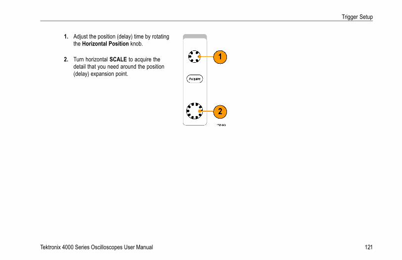
Trigger Setup
1. Adjust the position (delay) time by rotatingthe Horizontal Position knob.
2. Turn horizontal SCALE to acquire thedetail that you need around the position(delay) expansion point.
Tektronix 4000 Series Oscilloscopes User Manual 121

Trigger Setup
The part of the record that occurs before the trigger is the pretrigger portion. The part that occurs after the trigger is the posttriggerportion. Pretrigger data can help you troubleshoot. For example, to find the cause of an unwanted glitch in your test circuit, you cantrigger on the glitch and make the pretrigger period large enough to capture data before the glitch. By analyzing what happensbefore the glitch, you may uncover information that helps you find the source of the glitch. Alternatively, to see what is happening inyour system as a result of the trigger event, make the posttrigger period large enough to capture data after the trigger.
Slope and Level
The slope control determines whether theinstrument finds the trigger point on the risingor the falling edge of a signal.The level control determines where on thatedge the trigger point occurs.
The oscilloscope provides a long horizontal baror bars across the graticule to temporarily showthe trigger level.
122 Tektronix 4000 Series Oscilloscopes User Manual

Trigger Setup
1. Turn the front-panel Trigger Level knob toadjust the trigger level without going to amenu.
2. Push the front-panel Set to 50% button toquickly set the trigger level to the midpointof the waveform.
Tektronix 4000 Series Oscilloscopes User Manual 123

Trigger Setup
Choosing a Trigger TypeTo select a trigger:
1. Push Trigger Menu.
124 Tektronix 4000 Series Oscilloscopes User Manual

Trigger Setup
TriggerType
Sequence(B Trigger)
PulseWidth
Runt
Logic
Setup &Hold
Rise/FallTime
Video
2. Push Type to bring up the Trigger Typeside-bezel menu.
NOTE. The bus trigger in the MSO4000 seriesworks on parallel buses even without anapplication module. Using the bus trigger onother buses requires use of the DPO4EMBD,the DPO4AUTO, or the DPO4COMP applicationmodule.
Bus
3. Turn multipurpose knob a to select the desiredtrigger type.
Tektronix 4000 Series Oscilloscopes User Manual 125

Trigger Setup
4. Complete the trigger setup using thelower-bezel menu controls displayed for thetrigger type. The controls to set up the triggervary depending on the trigger type.
TypeEdge
Source1
CouplingDC
Slope Level100 mV
ModeAuto
& Holdoff
Selecting TriggersTrigger Type Trigger ConditionsEdge Trigger on a rising or falling edge, as defined by the slope
control. Coupling choices are DC, LF Reject, HF Reject,and Noise Reject.Edge triggers are the simplest and most commonly usedtrigger type, with both analog and digital signals. Anedge trigger event occurs when the trigger source passesthrough a specified voltage level in the specified direction.
126 Tektronix 4000 Series Oscilloscopes User Manual

Trigger Setup
Trigger Type Trigger ConditionsSequence (BTrigger)
Combine an edge A Event (Main) trigger with the B Event(Delayed) trigger to capture more complex signals. (Seepage 142, Using Sequence Trigger (A (Main) and B(Delayed)).)Time. After the A Event occurs, the trigger system waitsthe specified amount of time, and then looks for the B Eventbefore triggering and displaying the waveform.Events. After the A Event occurs, the trigger system looksfor a specified number of B Events before triggering anddisplaying the waveform.
Pulse Width Trigger on pulses that are less than, greater than, equal to,or not equal to a specified time. You can trigger on positiveor negative pulses. Pulse width triggers are primarily usedon digital signals.
Tektronix 4000 Series Oscilloscopes User Manual 127

Trigger Setup
Trigger Type Trigger ConditionsRunt Trigger on a pulse amplitude that crosses one threshold
but fails to cross a second threshold before recrossing thefirst. You can detect positive or negative (or either) runts, oronly those wider than, less than, greater than, equal to, ornot equal to a specified width. Runt triggers are primarilyused on digital signals.
Logic Trigger when a selected set of channels transition to aselected state. Use the Clock control side-bezel button toselect unclocked (pattern) triggering, or to select a clockchannel (state triggering).Use the Select control and the State control side-bezelbuttons to set each channel to High, Low, or Don’t Care (X).If you have selected Clock triggering, you can set the clockedge to rising or falling.For unclocked triggering, by default, triggering occurs whenthe selected condition goes true. You can also selecttriggering when the condition goes false, or time-qualifiedtriggering.You can use up to 20 channels for a logic trigger (4 analogand 16 digital) with MSO4000 series oscilloscopes.
NOTE. Optimum Logic trigger performance is achieved byusing only analog channels or only digital channels.
128 Tektronix 4000 Series Oscilloscopes User Manual

Trigger Setup
Trigger Type Trigger ConditionsSetup and Hold Trigger when a logic data input changes state inside of the
setup or hold time relative to a clock edge.Setup is the amount of time that data should be stable andnot change before a clock edge occurs. Hold is the timethat data should be stable and not change after a clockedge occurs.MSO4000 series oscilloscopes are capable of multiplechannel Setup and Hold triggering, and can monitor thestate of an entire bus for setup and hold violations. Youcan use up to 20 channels for a Setup and Hold trigger (4analog and 16 digital) with MSO4000 series oscilloscopes.Use the Clock control side-bezel button to select the clockchannel. Use the Select control and the Function control(MSO4000 series only) side-bezel buttons to select oneor more channels you want to monitor for setup and holdviolations.
NOTE. Optimum Setup and Hold trigger performanceis achieved by using only analog channels or only digitalchannels.
Tektronix 4000 Series Oscilloscopes User Manual 129

Trigger Setup
Trigger Type Trigger ConditionsRise/Fall Time Trigger on rise and fall times. Trigger on pulse edges that
traverse between two thresholds at faster or slower ratesthan the specified time. Specify pulse edges as positiveor negative or either.
130 Tektronix 4000 Series Oscilloscopes User Manual
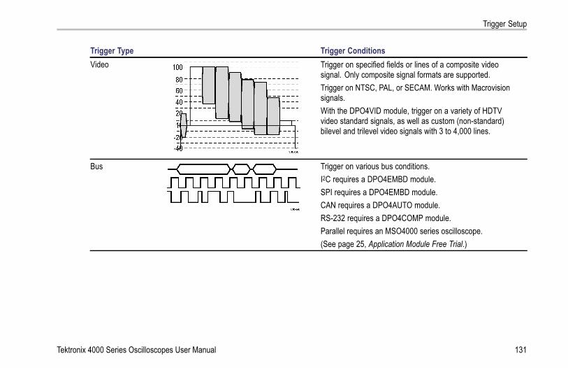
Trigger Setup
Trigger Type Trigger ConditionsVideo Trigger on specified fields or lines of a composite video
signal. Only composite signal formats are supported.Trigger on NTSC, PAL, or SECAM. Works with Macrovisionsignals.With the DPO4VID module, trigger on a variety of HDTVvideo standard signals, as well as custom (non-standard)bilevel and trilevel video signals with 3 to 4,000 lines.
Bus Trigger on various bus conditions.I2C requires a DPO4EMBD module.SPI requires a DPO4EMBD module.CAN requires a DPO4AUTO module.RS-232 requires a DPO4COMP module.Parallel requires an MSO4000 series oscilloscope.(See page 25, Application Module Free Trial.)
Tektronix 4000 Series Oscilloscopes User Manual 131

Trigger Setup
Triggering on BusesYou can use your oscilloscope to trigger on CAN, I2C, SPI, and RS-232 buses, if you have the DPO4AUTO, DPO4EMBD, orDPO4COMP application module installed. The MSO4000 series can trigger on parallel buses without an application module.The oscilloscope can display both physical layer (as analog waveforms) and protocol level information (as digital and symbolicwaveforms).
To set up the bus trigger:
1. If you have not already defined your bus usingthe front-panel B1 and B2 buttons (and B3 andB4 on the MSO4000 series), do so now. (Seepage 98, Setting Up a Serial or Parallel Bus.)
2. Push Trigger Menu.
132 Tektronix 4000 Series Oscilloscopes User Manual

Trigger Setup
3. Push Type. TypeBus
Source BusB1 (I2C)
Trigger OnAddress
Address07F
DirectionWrite
ModeAuto
& Holdoff
4. Turn multipurpose knob a to scroll through thetrigger type side menu until you select Bus.
B1 (I2C)5. Push Source Bus and turn multipurpose knoba to scroll through the source bus side menuuntil you select the bus that you want to triggeron.
B2(Parallel)
Tektronix 4000 Series Oscilloscopes User Manual 133

Trigger Setup
6. Push Trigger On and turn multipurpose knoba to scroll through the side-bezel menu untilyou select the desired trigger on feature.If you are using the parallel bus trigger, youcan trigger on a binary or hex data value.Push the lower-bezel Data button and enterthe parameters of interest with multipurposeknobs a and b.If you are using the I2C bus trigger, youcan trigger on Start, Repeated Start,Stop, Missing Ack, Address, Data, orAddress/Data.If you are using the SPI bus trigger, you cantrigger on SS Active, MOSI, MISO, or MOSI& MISO.If you are using the CAN bus trigger, you cantrigger on Start of Frame, Type of Frame,Identifier, Data, Id & Data, End of Frame,and Missing Ack.
If you are using the RS-232 bus trigger, youcan trigger on Tx Start Bit, Rx Start Bit, TxEnd of Packet, Rx End of Packet,Tx Data,or Rx Data.
134 Tektronix 4000 Series Oscilloscopes User Manual

Trigger Setup
7. If you are setting up an I2C trigger and havemade a Trigger On selection of Address orAddress/Data, push the lower-bezel Addressbutton to access the I2C Address side-bezelmenu.Push the side-bezel Addressing Modebutton and select 7 bit or 10 bit. Push theside-bezel Address button. Enter the addressparameters of interest with multipurpose knobsa and b.Then push the lower-bezel menu Directionbutton and select the direction of interest:Read, Write, or Read or Write.
Tektronix 4000 Series Oscilloscopes User Manual 135

Trigger Setup
If you have made a Trigger On selection ofData or Address/Data, push the lower-bezelData button to access the I2C Data side-bezelmenu.Push the Number of Bytes button and enterthe number of bytes with multipurpose knob a.Push the side-bezel Addressing Mode buttonand select 7 bit or 10 bit. Push the side-bezelData button. Enter the data parameters ofinterest with multipurpose knobs a and b.For more information on the I2C addressformats, refer to item 7 under Setting Up BusParameters.
136 Tektronix 4000 Series Oscilloscopes User Manual

Trigger Setup
8. If you are setting up an SPI trigger and havemade a Trigger On selection of MOSI orMISO, push the lower-bezel Data button, pushthe side-bezel MOSI (or MISO) button, andenter the data parameters of interest withmultipurpose knobs a and b.Then push the Number of Bytes button andenter the number of bytes with multipurposeknob a.If you select MOSI & MISO, push thelower-bezel Data button and enter theparameters of interest in the side-bezel menus.
Tektronix 4000 Series Oscilloscopes User Manual 137

Trigger Setup
9. If you are setting up a CAN trigger and havemade a Trigger On selection of Type ofFrame, push the lower-bezel Frame Typebutton, and select Data Frame, RemoteFrame, Error Frame, or Overload Frame.If you have made a Trigger On selection ofIdentifier, push the lower-bezel Identifierbutton, and select a Format. Then push theIdentifier side-bezel button, and enter a binaryor hex value with multipurpose knobs a and b.Push the lower-bezel menu Direction buttonand select the direction of interest: Read,Write, or Read or Write.If you have made a Trigger On selectionof Data. Push the lower-bezel Data buttonand enter the parameters of interest withmultipurpose knobs a and b.
138 Tektronix 4000 Series Oscilloscopes User Manual

Trigger Setup
10. If you are setting up an RS-232 trigger andhave made a Trigger On selection of Tx Dataor Rx Data, push the lower-bezel Data button.Push the Number of Bytes button and enterthe number of bytes with multipurpose knob a.Push the side-bezel Data button, and enterthe parameters of interest with multipurposeknobs a and b.
I2C, SPI, and CAN Bus Trigger Data MatchingRolling window byte matching for I2C and SPI. To use a rolling window to trigger on data, you define the number of bytes tomatch. Then the oscilloscope uses a rolling window to find any match within a packet, with the window rolling one byte at a time.
For example, if the number of bytes is one, the oscilloscope will attempt to match the first byte, second byte, third, and soon within the packet.
If the number of bytes is two, the oscilloscope will try to match any two consecutive bytes, such as one and two, two and three,three and four, and so on. If the oscilloscope finds a match, it will trigger.
Specific byte matching (non-rolling window matching for a specific position in the packet) for I2C, SPI, andCAN. You can trigger on a specific byte for I2C, SPI, and CAN in several ways:
For I2C and SPI, enter the number of bytes to match the number of bytes in the signal. Then use don’t cares (X) to mask thebytes that you are not interested in.
Tektronix 4000 Series Oscilloscopes User Manual 139

Trigger Setup
For I2C, push the lower-bezel Trigger On to trigger on Address/Data. Push Address. On the side-bezel menu, push Address,and rotate multipurpose knobs a and b as needed. Set the address to don’t cares (X) if you want to mask the address. Thedata will be matched starting at the first byte without using a rolling window.
For CAN, triggering occurs when the user-selected data input matches the data and qualifier in the signal starting at the firstbyte. Set the number of bytes to match the number of bytes of interest. Use the data qualifier to perform: =, !=, <, >, >=,and <= operations. Triggering on identifier and data always matches the identifier and data selected by the user, with thedata starting at the first byte. No rolling window is used.
140 Tektronix 4000 Series Oscilloscopes User Manual
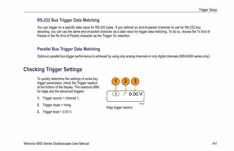
Trigger Setup
RS-232 Bus Trigger Data MatchingYou can trigger on a specific data value for RS-232 bytes. If you defined an end-of-packet character to use for RS-232 busdecoding, you can use the same end-of-packet character as a data value for trigger data matching. To do so, choose the Tx End ofPacket or the Rx End of Packet character as the Trigger On selection.
Parallel Bus Trigger Data MatchingOptimum parallel bus trigger performance is achieved by using only analog channels or only digital channels (MSO4000 series only).
Checking Trigger SettingsTo quickly determine the settings of some keytrigger parameters, check the Trigger readoutat the bottom of the display. The readouts differfor edge and the advanced triggers.
1. Trigger source = channel 1.
2. Trigger slope = rising.
3. Trigger level = 0.00 V.Edge trigger readout
Tektronix 4000 Series Oscilloscopes User Manual 141

Trigger Setup
Using Sequence Trigger (A (Main) and B (Delayed))Combine an edge A Event (Main) trigger with the B Event (Delayed) trigger to capture more complex signals. After the A Eventoccurs, the trigger system looks for the B Event before triggering and displaying the waveform.
A and B triggers can (and typically do) have separate sources.
Use the Edge trigger menu to set up the A trigger first. Then, to use the B trigger:
1. Push Trigger Menu.
2. Push Type.
3. Turn multipurpose knob a to select a triggertype of Sequence (B Trigger).This brings up the Sequence (B Trigger) menu.
4. Push B Trigger After A. TypeSequence(B Trigger)
Source1
CouplingDC
Slope Level0.00 V
B TriggerAfter ATime
ModeAuto
& Holdoff
142 Tektronix 4000 Series Oscilloscopes User Manual

Trigger Setup
Push a side-bezel button to select sequencingthe B trigger after the A as Time or as Events.
Time(a) 8 ns
B Events1
Set toMinimum
5. Set the other Sequence Trigger parameters inthe related side- and lower-bezel menus.
B Trigger After Delay Time
The A trigger arms the instrument. Posttriggeracquisition starts on the first B edge after thetrigger delay time.
Tektronix 4000 Series Oscilloscopes User Manual 143

Trigger Setup
Trigger on B Events
The A trigger arms the instrument. Posttriggeracquisition starts on the nth B event.
Quick TipsB-trigger delay time and horizontal position are independent functions. When you establish a trigger condition using either theA trigger alone or the A and B triggers together, you can also use the horizontal position control to delay the acquisition by anadditional amount.
When using the B trigger, the A and B trigger types can only be Edge.
144 Tektronix 4000 Series Oscilloscopes User Manual

Trigger Setup
Starting and Stopping an AcquisitionAfter you have defined the acquisition and trigger parameters, start the acquisition with Run/Stop or Single.
Push Run/Stop to start acquisitions. Theoscilloscope acquires repeatedly untilyou push the button again to stop theacquisition.
Push Single to take a single acquisition.Single sets the trigger mode to Normal forthe single acquisition.
Tektronix 4000 Series Oscilloscopes User Manual 145

Display Waveform Data
Display Waveform DataThis section contains concepts and procedures for displaying the acquired waveform.
Adding and Removing a Waveform1. To add or remove a waveform from the
display, push the corresponding front-panelchannel button or the D15-D0 button.You can use the channel as a triggersource whether or not it is displayed.
146 Tektronix 4000 Series Oscilloscopes User Manual

Display Waveform Data
Setting the Display Style and Persistence1. To set the display style, push Acquire.
2. Push Waveform Display. ModeSample
RecordLength
10k
ResetHorizontalPosition
WaveformDisplay
XY DisplayOn
Tektronix 4000 Series Oscilloscopes User Manual 147

Display Waveform Data
3. Push Dots Only On Off from the side-bezelmenu. Dots on will display the waveformrecord points as dots on the screen. Dots offconnects the dots with vectors.
WaveformDisplay
Dots Only
On |Off
4. Push Persist Time, and turn multipurposeknob a to have waveform data remain onscreen for a user-specified amount of time.
PersistTime
(a) Auto
5. Push Set to Auto to have the oscilloscopeautomatically determine a persistence time foryou.
Set to Auto
6. Push Clear Persistence to reset thepersistence information.
Clear Per-sistence
7. To display the amplitude from one waveformagainst the amplitude from another, push XYDisplay. Then push Triggered XY from theside menu.A data point from the first waveform specifiesthe horizontal location while the correspondingdata point from the second waveform specifiesthe vertical location for each displayed point.
148 Tektronix 4000 Series Oscilloscopes User Manual

Display Waveform Data
Quick TipsVariable persistence accumulates record points for a specified time interval. Each record point decays independently accordingto the time interval. Use variable persistence for displaying infrequently appearing signal anomalies, such as glitches.
Infinite persistence continuously accumulates record points until you change one of the acquisition display settings. Use infinitepersistence for displaying unique signal anomalies, such as glitches.
The XY Display mode graphs the data in fixed pairs of waveforms against one another. You can use CH1 versus CH2, andREF1 versus REF2. On four-channel models, you can also use CH3 versus CH4, and REF3 versus REF4.
When the XY Display is on, an upper window appears that displays data versus time.
Setting the Graticule Style
1. To set the graticule style, push Utility.
2. Push Utility Page. Utility Page
Tektronix 4000 Series Oscilloscopes User Manual 149

Display Waveform Data
3. Turn multipurpose knob a and select Display. Display
4. Push Graticule from the lower-bezel menu. Utility PageDisplay
BacklightIntensity
High
GraticuleFull
5. Select the desired style from the resultingside-bezel menu.Use the Full graticule for quick estimates ofwaveform parameters.Use the Grid graticule for full-screenmeasurements with cursors and automaticreadouts when cross hairs are not needed.Use the Cross Hair graticule for making quickestimates of waveforms while leaving moreroom for automatic readouts and other data.Use the Frame graticule with automaticreadouts and other screen text when displayfeatures are not needed.
150 Tektronix 4000 Series Oscilloscopes User Manual

Display Waveform Data
Quick TipsYou can display IRE and mV graticules. To do this, set the trigger type to video and set the vertical scale to 114 mV/division.(The 114 mV/division selection is available in the coarse vertical scale settings for the channel when you set the trigger type tovideo.) The oscilloscope will automatically display the IRE graticule for NTSC signals, and the mV graticule for other videosignals (PAL, SECAM, HDTV, and custom).
Setting the LCD Backlight
1. Push Utility.
2. Push Utility Page. Utility Page
3. Turn multipurpose knob a and select Display. Display
Tektronix 4000 Series Oscilloscopes User Manual 151

Display Waveform Data
4. Push Backlight Intensity. Utility PageDisplay
BacklightIntensity
High
GraticuleFull
BacklightIntensity
High
Medium
5. Select the intensity level from the resultingside-bezel menu. Choices are: High, Medium,and Low.
Low
Setting Waveform Intensity1. Push the front-panel Intensity button.
152 Tektronix 4000 Series Oscilloscopes User Manual

Display Waveform Data
This will bring up the intensity readout on thedisplay.
2. Rotate multipurpose knob a to select thedesired waveform intensity.
3. Rotate multipurpose knob b to select thedesired intensity for the graticule.
4. Push Intensity again to clear the intensityreadout from the display.
Tektronix 4000 Series Oscilloscopes User Manual 153

Display Waveform Data
Scaling and Positioning a WaveformUse the horizontal controls to adjust the time base, adjust the trigger point, and to examine waveform details more closely. You canalso use the Wave Inspector Pan and Zoom controls to adjust the display of waveforms. (See page 203, Using Wave Inspectorto Manage Long Record Length Waveforms.)
Original waveform Scaled horizontally Positioned horizontally
154 Tektronix 4000 Series Oscilloscopes User Manual

Display Waveform Data
Use the vertical controls to select waveforms, adjust the waveform vertical position and scale, and set input parameters. Push achannel menu button (1, 2, 3, or 4), button as many times as needed and the associated menu items to select, add, or removea waveform.
Original waveform Scaled vertically Positioned vertically
Quick TipsPreview. If you change the Position or Scale controls when the acquisition is stopped or when it is waiting for the next trigger,the oscilloscope rescales and repositions the relevant waveforms in response to the new control settings. It simulates what youwill see when you next push the RUN button. The oscilloscope uses the new settings for the next acquisition.
You may see a clipped waveform if the original acquisition went off the screen.
The math waveform, cursors, and automatic measurements remain active and valid when using preview.
Tektronix 4000 Series Oscilloscopes User Manual 155

Display Waveform Data
Setting Input ParametersUse the vertical controls to select waveforms, adjust the waveform vertical position and scale, and set input parameters.
1. Push a channel menu button 1, 2, 3, or 4 tobring up the vertical menu for the designatedwaveform. The vertical menu only affects theselected waveform.
Pushing a channel button will also select orcancel that waveform selection.
2. Push Coupling repeatedly to select thecoupling to use.Use DC coupling to pass both AC and DCcomponents.
Coupling
DC| AC
Impedance
1MΩ| 50Ω
Invert
On |Off
BandwidthFull
(1) Label
More
Use AC coupling to block the DC componentand show only the AC signal.Use Ground (GND) to display the referencepotential.
156 Tektronix 4000 Series Oscilloscopes User Manual

Display Waveform Data
3. Push Impedance repeatedly to select theinput impedance to use.Set the input impedance (termination) to50 Ω or 1 MΩ if using DC or Gnd coupling.Input impedance is automatically set to 1 MΩwhen using AC coupling.For more information on input impedance, seeQuick Tips. (See page 160, Quick Tips.)
4. Push Invert to invert the signal.Select Off for normal operation and Onto invert the polarity of the signal in thepreamplifier.
5. Push Bandwidth, and select the desiredbandwidth from the resulting side-bezel menu.The set choices are: Full, 250 MHz, and20 MHz. Additional choices may appear,depending on the probe that you use.Select Full to set the bandwidth to the fulloscilloscope bandwidth.Select 250 MHz to set the bandwidth to250 MHz.Select 20 MHz to set the bandwidth to 20 MHz.
Tektronix 4000 Series Oscilloscopes User Manual 157

Display Waveform Data
6. Push Label to create a label for the channel.(See page 82, Labeling Channels and Buses.)
7. Push More to access additional side-bezelmenus.
8. Select Fine Scale to enable multipurposeknob a to make fine vertical scale adjustments.
Fine Scale
Offset
Position
ProbeSetup
Deskew
158 Tektronix 4000 Series Oscilloscopes User Manual

Display Waveform Data
9. Select Offset to enable multipurpose knob ato make vertical offset adjustments.On the side-bezel menu, choose Set to 0 V toset the vertical offset to 0 V.For more information on offset, see QuickTips. (See page 160, Quick Tips.)
10. Select Probe Setup to define probeparameters.On the resulting side-bezel menu:
Select Voltage or Current to set theprobe type for probes that do not have theTekProbe II or TekVPI interface.
Use multipurpose knob a to set theattenuation to match the probe.
11. Select Deskew to set the time skew correctionfor the channel. Turn multipurpose knob a toadjust the time skew (deskew) correction forthe probe attached to the selected channel.This shifts acquisition and display of thewaveform left or right, relative to the triggertime. Use this to compensate for differences incable lengths or probe types.
Tektronix 4000 Series Oscilloscopes User Manual 159
Display Waveform Data
Quick TipsUsing Probes with the TekProbe II and TekVPI Interfaces. When you attach a probe with the TekProbe II or the TekVPIinterface, the oscilloscope sets the channel sensitivity, coupling, and termination resistance automatically to match the proberequirements. Tek Probe II probes require use of the TPA-BNC Adapter.
The Difference Between Vertical Position and Offset. Vertical position is a display function. Adjust the vertical position toplace the waveforms where you want to see them. The waveform baseline locations track adjustments made to their positions.
When you adjust vertical offset, you see a similar effect, but it is actually quite different. Vertical offset is applied before theoscilloscope preamplifier and can be used to increase the effective dynamic range of the inputs. For example, you can usevertical offset to look at small variations in a large DC voltage. Set the vertical offset to match the nominal DC voltage andthe signal appears in the center of the screen.
50 Ω Protection. If you select 50 Ω termination, the maximum vertical scale factor is limited to 1 V/div, except that with a 10Xprobe the scale factor is 10 V. If you apply excessive input voltage, the oscilloscope automatically switches to 1 MΩ terminationto protect the internal 50 Ω termination. For more details, refer to the specifications in the Tektronix 4000 Series OscilloscopesTechnical Reference.
160 Tektronix 4000 Series Oscilloscopes User Manual

Display Waveform Data
Positioning and Labeling Bus SignalsPositioning Bus Signals. Push the appropriate front-panel bus button and turn multipurpose knob a to adjust the verticalposition of the selected bus. (See page 98, Setting Up a Serial or Parallel Bus.)
1. Push the appropriate front-panel bus buttonto select that bus.
2. Turn multipurpose knob a to adjust the verticalposition of the selected bus.
Tektronix 4000 Series Oscilloscopes User Manual 161

Display Waveform Data
Labeling Bus Signals. To label a bus, do the following steps:
1. Push the appropriate front-panel bus button.
2. Push Label.(See page 82, Labeling Channels and Buses.)
Bus (B1)Parallel
DefineInputs
Thresholds (B1) LabelParallel
Bus Display Event Table
162 Tektronix 4000 Series Oscilloscopes User Manual

Display Waveform Data
Positioning, Scaling, and Grouping Digital Channels1. Push the front-panel D15–D0 button.
2. Push the lower-bezel D15–D0 menu item. D15 – D0On/Off
Thresholds Edit Labels MagniVu
On |Off
Height
S | M L
Tektronix 4000 Series Oscilloscopes User Manual 163

Display Waveform Data
3. Push the side-bezel Select button. Select(a) D0
(b) 1.04 div
Display
On| Off
Turn onD7–D0
Turn onD15–D8
4. Turn multipurpose knob a to select the channelto move.
164 Tektronix 4000 Series Oscilloscopes User Manual
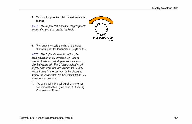
Display Waveform Data
5. Turn multipurpose knob b to move the selectedchannel.
NOTE. The display of the channel (or group) onlymoves after you stop rotating the knob.
6. To change the scale (height) of the digitalchannels, push the lower-menu Height button.
NOTE. The S (Small) selection will displayeach waveform at 0.2 divisions tall. The M(Medium) selection will display each waveformat 0.5 divisions tall. The L (Large) selection willdisplay each waveform at 1 division tall. L onlyworks if there is enough room in the display todisplay the waveforms. You can display up to 10 Lwaveforms at one time.
7. You can label individual digital channels foreasier identification. (See page 82, LabelingChannels and Buses.)
Tektronix 4000 Series Oscilloscopes User Manual 165

Display Waveform Data
8. To group some or all of the digital channelstogether, move the channels right next to eachother. All the channels that are next to eachother automatically form a group.You can see the groups by pressingthe side-bezel Select item and turningmultipurpose knob a.When a group is selected, turn multipurposeknob b to move the whole group.
166 Tektronix 4000 Series Oscilloscopes User Manual

Display Waveform Data
Viewing Digital ChannelsThe various ways of displaying data from the digital channels help you analyze the signals. Digital channels store a high orlow state for each sample.
Logic high levels are displayed in green. Logic low levels are displayed in blue. When a single transition occurs during the timerepresented by one pixel column, the transition (edge) is displayed in gray.
When multiple transitions occur during the time representedby one pixel column, the transition (edge) is displayed inwhite.When the display shows a white edge, indicating multipletransitions, you may be able to zoom in and see theindividual edges.
When you are zoomed in so far that there is more thanone pixel column per sample, the uncertainty of the edgeposition is indicated by light gray shading.
NOTE. When the light gray shading is displayed, useMagniVu.
Tektronix 4000 Series Oscilloscopes User Manual 167

Analyze Waveform Data
Analyze Waveform DataAfter having properly set up the acquisition, triggering, and display of your desired waveform, you can then analyze the results.Select from features such as cursors, automatic measurements, statistics, math, and FFT.
NOTE. Automatic measurements are not available for digital channels.
Taking Automatic MeasurementsTo take an automatic measurement:
1. Push Measure.
168 Tektronix 4000 Series Oscilloscopes User Manual

Analyze Waveform Data
2. Push Select Measurement. SelectMeasure-
ment1
RemoveMeasure-
ment
GatingScreen
StatisticsOn
ReferenceLevels
Indicators ConfigureCursors
3. Turn multipurpose knob a to select the channelfrom which you want to measure. This step isonly needed if you are acquiring data on morethan one channel.
4. Select the specific measurement ormeasurements from the side-bezel menu.
5. To remove a measurement, push RemoveMeasurement and the specific measurementfrom the resulting side-bezel menu.
Tektronix 4000 Series Oscilloscopes User Manual 169
Analyze Waveform Data
Quick TipsTo remove all measurements, select Remove All.
A symbol appears instead of the expected numerical measurement if a vertical clipping condition exists. Part of thewaveform is above or below the display. To obtain a proper numerical measurement, turn the vertical scale and positionknobs to make all of the waveform appear in the display.
170 Tektronix 4000 Series Oscilloscopes User Manual

Analyze Waveform Data
Selecting Automatic MeasurementsThe following tables list each automatic measurement by category: time or amplitude. (See page 168, Taking AutomaticMeasurements.)
Time Measurements
Measurement DescriptionPeriod The time required to complete the first cycle in a waveform or gated region. Period is the
reciprocal of frequency and is measured in seconds.
Frequency The first cycle in a waveform or gated region. Frequency is the reciprocal of the period; it ismeasured in hertz (Hz) where one Hz is one cycle per second.
Delay The time between the mid reference (default 50%) amplitude point of two different waveforms.See also Phase.
Rise Time The time required for the leading edge of the first pulse in the waveform or gated regionto rise from the low reference value (default = 10%) to the high reference value (default= 90%) of the final value.
Fall Time The time required for the falling edge of the first pulse in the waveform or gated region to fallfrom the high reference value (default = 90%) to the low reference value (default = 10%) ofthe final value.
Positive DutyCycle
The ratio of the positive pulse width to the signal period expressed as a percentage. The dutycycle is measured on the first cycle in the waveform or gated region.
Tektronix 4000 Series Oscilloscopes User Manual 171

Analyze Waveform Data
Time Measurements (cont.)
Measurement DescriptionNegative DutyCycle
The ratio of the negative pulse width to the signal period expressed as a percentage. Theduty cycle is measured on the first cycle in the waveform or gated region.
Positive PulseWidth
The distance (time) between the mid reference (default 50%) amplitude points of a positivepulse. The measurement is made on the first pulse in the waveform or gated region.
Negative PulseWidth
The distance (time) between the mid reference (default 50%) amplitude points of a negativepulse. The measurement is made on the first pulse in the waveform or gated region.
Burst Width The duration of a burst (a series of transient events) and is measured over the entirewaveform or gated region.
Phase The amount of time that one waveform leads or lags another waveform, expressed in degreeswhere 360° makes up one waveform cycle. See also Delay.
172 Tektronix 4000 Series Oscilloscopes User Manual

Analyze Waveform Data
Amplitude Measurements
Measurement DescriptionPositiveOvershoot
This is measured over the entire waveform or gated region and is expressed as:Positive Overshoot = (Maximum – High) / Amplitude x 100%.
NegativeOvershoot
This is measured over the entire waveform or gated region and is expressed as:Negative Overshoot = (Low – Minimum) / Amplitude x 100%.
Tektronix 4000 Series Oscilloscopes User Manual 173

Analyze Waveform Data
Amplitude Measurements (cont.)
Measurement DescriptionPk-Pk The absolute difference between the maximum and minimum amplitude in the entire
waveform or gated region.
Amplitude The high value less the low value measured over the entire waveform or gated region.
High This value is used as 100% whenever high reference, mid reference, or low referencevalues are needed, such as in fall time or rise time measurements. Calculate using eitherthe min/max or histogram method. The min/max method uses the maximum value found.The histogram method uses the most common value found above the midpoint. This value ismeasured over the entire waveform or gated region.
Low This value is used as 0% whenever high reference, mid reference, or low reference values areneeded, such as in fall time or rise time measurements. Calculate using either the min/maxor histogram method. The min/max method uses the minimum value found. The histogrammethod uses the most common value found below the midpoint. This value is measuredover the entire waveform or gated region.
Max The most positive peak voltage. Max is measured over the entire waveform or gated region.
Min The most negative peak voltage. Min is measured over the entire waveform or gated region.
174 Tektronix 4000 Series Oscilloscopes User Manual

Analyze Waveform Data
Amplitude Measurements (cont.)
Measurement DescriptionMean The arithmetic mean over the entire waveform or gated region.
Cycle Mean The arithmetic mean over the first cycle in the waveform or the first cycle in the gated region.
RMS The true Root Mean Square voltage over the entire waveform or gated region.
Cycle RMS The true Root Mean Square voltage over the first cycle in the waveform or the first cyclein the gated region.
Tektronix 4000 Series Oscilloscopes User Manual 175

Analyze Waveform Data
Miscellaneous Measurements
Measurement DescriptionArea Area measurement is a voltage over time measurement. It returns the area over the entire
waveform or gated region in volt-seconds. Area measured above ground is positive; areameasured below ground is negative.
Cycle Area A voltage over time measurement. The measurement is the area over the first cycle in thewaveform or the first cycle in the gated region expressed in volt-seconds. The area abovethe common reference point is positive, and the area below the common reference point isnegative.
176 Tektronix 4000 Series Oscilloscopes User Manual
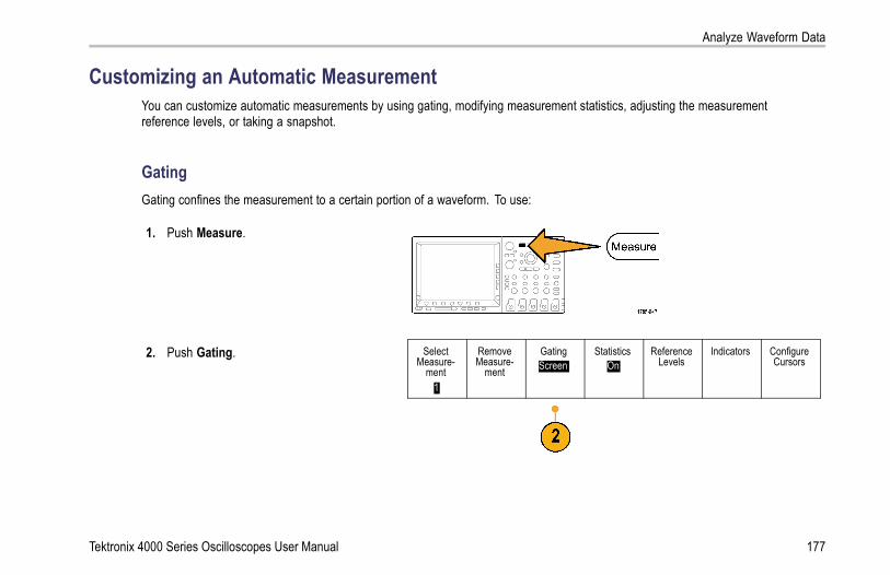
Analyze Waveform Data
Customizing an Automatic MeasurementYou can customize automatic measurements by using gating, modifying measurement statistics, adjusting the measurementreference levels, or taking a snapshot.
GatingGating confines the measurement to a certain portion of a waveform. To use:
1. Push Measure.
2. Push Gating. SelectMeasure-
ment1
RemoveMeasure-
ment
GatingScreen
StatisticsOn
ReferenceLevels
Indicators ConfigureCursors
Tektronix 4000 Series Oscilloscopes User Manual 177

Analyze Waveform Data
3. Position the gates from the side-bezel menuoptions.
Gating
Off(Full
Record)
Screen
BetweenCursors
BringCursors on
Screen
178 Tektronix 4000 Series Oscilloscopes User Manual

Analyze Waveform Data
StatisticsStatistics characterize the stability of measurements. To adjust statistics:
1. Push Measure.
2. Push Statistics. SelectMeasure-
ment1
RemoveMeasure-
ment
GatingScreen
StatisticsOn
ReferenceLevels
Indicators ConfigureCursors
Tektronix 4000 Series Oscilloscopes User Manual 179

Analyze Waveform Data
Measure-ment Sta-
tistics
On| Off
Mean &Std DevSamples
(a) |32
3. Push the side-bezel menu options. Theseinclude whether to turn statistics on or offand how many samples to use for mean andstandard deviation calculations.
ResetStatistics
SnapshotTo see all the single-sourced measurements at one moment in time:
1. Push Measure.
180 Tektronix 4000 Series Oscilloscopes User Manual

Analyze Waveform Data
2. Push Select Measurement. SelectMeasure-
ment1
RemoveMeasure-
ment
GatingScreen
StatisticsOn
ReferenceLevels
Indicators ConfigureCursors
3. Push Snapshot All Measurements. SnapshotAll Mea-
surements
4. View results.
Tektronix 4000 Series Oscilloscopes User Manual 181

Analyze Waveform Data
Snapshot on 1
Period+Width
Burst WRise
+Duty+Over
HighMax
AmplMeanRMSArea
: 312.2μs: 103.7μs: 936.5μs: 1.452μs: 33.23%: 7.143%: 9.200 V: 10.40 V: 16.80 V: -5.396 V: 7.769 V: -21.58mVs
Freq–Width
Fall–Duty–Over
LowMin
Pk-PkCycleMeanCycleRMSCycleArea
: 3.203kHz: 208.5μs
: 1.144μs: 66.77 %: 7.143 %: -7.600 V: -8.800 V: 19.20 V: -5.396 V: 8.206 V: -654.6μVs
182 Tektronix 4000 Series Oscilloscopes User Manual

Analyze Waveform Data
Reference Levels
Reference levels determine how time-relatedmeasurements are taken. For example, they areused in calculating rise and fall times.
1. Push Measure.
2. Push Reference Levels. SelectMeasure-
ment1
RemoveMeasure-
ment
GatingScreen
StatisticsOn
ReferenceLevels
Indicators ConfigureCursors
Tektronix 4000 Series Oscilloscopes User Manual 183

Analyze Waveform Data
3. Set the levels from the side-bezel menu. ReferenceLevels
Set Levelsin
% |Units
Use High and Low reference to calculate riseand fall times.
High Ref(a) 90.0 %
Use Mid reference primarily for measurementsbetween edges such as pulse widths.
Mid Ref50.0 %50.0 %
Low Ref10.0 %
- more -1 of 2
184 Tektronix 4000 Series Oscilloscopes User Manual

Analyze Waveform Data
Taking Manual Measurements with CursorsCursors are on-screen markers that you position in the waveform display to take manual measurements on acquired data. Theyappear as horizontal and/or as vertical lines. To use cursors on analog or digital channels:
1. Push Cursors.This changes the cursor state. The threestates are:
No cursors appear on the screen.
Two vertical waveform cursors appear.They are attached to the selectedanalog waveform or digital waveforms.
Four screen cursors appear. Two arevertical and two are horizontal. Theyare no longer specifically attached to awaveform.
For example, the first time you pushCursors the state might be off.
Tektronix 4000 Series Oscilloscopes User Manual 185

Analyze Waveform Data
2. Push Cursors again.In the example, two vertical cursors appearon the selected screen waveform. As youturn multipurpose knob a, you move onecursor to the right or left. As you turn knobb, you move the other cursor.If you change the selected waveform bypushing the front-panel 1, 2, 3, 4, M, R, orD15-D0 button, both cursors jump to thenew selected waveform.
3. Push Select.This turns the cursor linking on and off. Iflinking is on, turning multipurpose knob amoves the two cursors together. Turningmultipurpose knob b adjusts the timebetween the cursors.
186 Tektronix 4000 Series Oscilloscopes User Manual

Analyze Waveform Data
4. Push Fine to toggle between a coarse anda fine adjustment for multipurpose knobsa and b.Pushing Fine also changes the sensitivityof other knobs as well.
5. Push Cursors again.This will put the cursors into screen mode.Two horizontal bars and two vertical barsspan the graticule.
6. Turn multipurpose knobs a and b to movethe pair of horizontal cursors.
Tektronix 4000 Series Oscilloscopes User Manual 187

Analyze Waveform Data
7. Push Select.This makes the vertical cursors active andthe horizontal ones inactive. Now, as youturn the multipurpose knobs, the verticalcursors will move.Push Select again to make the horizontalcursors active again.
8. View the cursor and the cursor readout.You can take timing measurementswith cursors on digital channels, but notamplitude measurements.
188 Tektronix 4000 Series Oscilloscopes User Manual

Analyze Waveform Data
9. Push Cursors again. This will turn off thecursor mode. The screen will no longerdisplay the cursors and the cursor readout.
Using Cursor ReadoutsCursor readouts supply textual and numeric information relating to the current cursor positions. The oscilloscope always showsthe readouts when the cursors are turned on.
Readouts appear in the upper right corner of the graticule. If Zoom is on, the readout appears in the upper right corner of thezoom window.
When a bus is selected, the readout shows the decoded bus data in the format you have selected, hexadecimal, binary, or ASCII(RS-232 only). When a digital channel is selected, the cursors show the values of all displayed digital channels.
NOTE. When serial buses are selected, the data value at that point is displayed in the cursor readout. When parallel busesare selected, no readout appears.
Tektronix 4000 Series Oscilloscopes User Manual 189

Analyze Waveform Data
Δ Readout:The Δ readouts indicate the difference betweenthe cursor positions.
a Readout:Indicates that the value is controlled bymultipurpose knob a.
b Readout:Indicates that the value is controlled bymultipurpose knob b.
The horizontal cursor lines on the displaymeasure the vertical parameters, typicallyvoltage.
The vertical cursor lines on the display measurehorizontal parameters, typically time.
190 Tektronix 4000 Series Oscilloscopes User Manual

Analyze Waveform Data
The square and circle shapes in the readout map to the multipurpose knobs when both vertical and horizontal cursors are present.
Using XY CursorsWhen the XY Display mode is on, the cursor readouts will appear to the right of the lower graticule (XY). They will include rectangular,polar, product, and ratio readouts. The oscilloscope will display vertical-bar waveform cursors in the upper graticule (YT).
Using Math WaveformsCreate math waveforms to support the analysis of your channel and reference waveforms. By combining and transforming sourcewaveforms and other data into math waveforms, you can derive the data view that your application requires.
NOTE. Math waveforms are not available for use with serial buses.
Use the following procedure for executing simple (+, –, *, ÷) math operations on two waveforms:
1. Push Math.
Tektronix 4000 Series Oscilloscopes User Manual 191

Analyze Waveform Data
2. Push Dual Wfm Math. Dual WfmMath
FFT AdvancedMath
(M) Label
3. On the side-bezel menu, set the sourcesto either channel 1, 2, 3, 4, or referencewaveforms R1, 2, 3, or 4. Choose the +, –,x, or ÷ operators.
4. For example, you might calculate power bymultiplying a voltage waveform and a currentwaveform.
192 Tektronix 4000 Series Oscilloscopes User Manual

Analyze Waveform Data
Quick TipsMath waveforms can be created from channel or reference waveforms or a combination of them.
Measurements can be taken on math waveforms in the same way as on channel waveforms.
Math waveforms derive their horizontal scale and position from the sources in their math expressions. Adjusting these controlsfor the source waveforms also adjusts the math waveform.
You can zoom in on math waveforms using the inner knob of the Pan-Zoom control. Use the outer knob for positioning thezoomed area. (See page 203, Using Wave Inspector to Manage Long Record Length Waveforms.)
Tektronix 4000 Series Oscilloscopes User Manual 193

Analyze Waveform Data
Using FFTAn FFT breaks down signals into component frequencies, which the oscilloscope uses to display a graph of the frequency domainof a signal, as opposed to the oscilloscope’s standard time domain graph. You can match these frequencies with known systemfrequencies, such as system clocks, oscillators, or power supplies.
1. Push Math.
2. Push FFT. Dual WfmMath
FFT AdvancedMath
(M) Label
194 Tektronix 4000 Series Oscilloscopes User Manual

Analyze Waveform Data
3. Push the side-bezel menu FFT Source buttonrepeatedly to select the source to use. Choicesare: channels 1, 2, 3, 4, reference waveforms1, 2, 3, and 4.
FFT
FFT Source1
4. Push the side-bezel Vertical Scale buttonrepeatedly to select either Linear RMS or dBVRMS.
VerticalUnits
Linear RMS
5. Push the side-bezel Window button repeatedlyto select the desired window.Window choices are: Rectangular, Hamming,Hanning, and Blackman-Harris.
WindowHanning
6. Push the side-bezel Horizontal button toactivate multipurpose knobs a and b to panand zoom the FFT display.
Horizontal625kHz
1.25kHz/div
Tektronix 4000 Series Oscilloscopes User Manual 195

Analyze Waveform Data
7. The FFT will appear on the display.
Quick TipsUse short record lengths for faster instrument response.
Use long record lengths to lower the noise relative to the signal and increase the frequency resolution.
196 Tektronix 4000 Series Oscilloscopes User Manual

Analyze Waveform Data
If desired, use the zoom feature along with the horizontal Position and Scale controls to magnify and position the FFTwaveform.
Use the default dBV RMS scale to see a detailed view of multiple frequencies, even if they have very different amplitudes. Usethe linear RMS scale to see an overall view of how all frequencies compare to each other.
The FFT feature provides four windows. Each is a trade-off between frequency resolution and magnitude accuracy. What youwant to measure and your source signal characteristics help determine which window to use. Use the following guidelinesto select the best window.
Description WindowRectangularThis is the best type of window for resolving frequencies that are very close to the same value butworst for accurately measuring the amplitude of those frequencies. It is the best type for measuringthe frequency spectrum of nonrepetitive signals and measuring frequency components near DC.Use Rectangular for measuring transients or bursts where the signal level before and after theevent are nearly equal. Also, use this window for equal-amplitude sine waves with frequencies thatare very close and for broadband random noise with a relatively slow varying spectrum.HammingThis is a very good window for resolving frequencies that are very close to the same value withsomewhat improved amplitude accuracy over the rectangular window. It has a slightly betterfrequency resolution than the Hanning.Use Hamming for measuring sine, periodic, and narrow band random noise. This window workson transients or bursts where the signal levels before and after the event are significantly different.
Tektronix 4000 Series Oscilloscopes User Manual 197

Analyze Waveform Data
Description WindowHanningThis is a very good window for measuring amplitude accuracy but less so for resolving frequencies.Use Hanning for measuring sine, periodic, and narrow band random noise. This window works ontransients or bursts where the signal levels before and after the event are significantly different.Blackman-Harris:This is the best window for measuring the amplitude of frequencies but worst at resolvingfrequencies.Use Blackman-Harris for measuring predominantly single frequency waveforms to look for higherorder harmonics.
Using Advanced MathThe advanced math feature lets you create a custom math waveform expression that can incorporate active and referencewaveforms, measurements, and/or numeric constants. To use this feature:
1. Push Math.
198 Tektronix 4000 Series Oscilloscopes User Manual
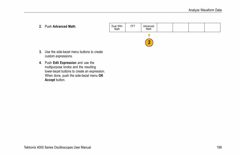
Analyze Waveform Data
2. Push Advanced Math. Dual WfmMath
FFT AdvancedMath
3. Use the side-bezel menu buttons to createcustom expressions.
4. Push Edit Expression and use themultipurpose knobs and the resultinglower-bezel buttons to create an expression.When done, push the side-bezel menu OKAccept button.
Tektronix 4000 Series Oscilloscopes User Manual 199

Analyze Waveform Data
For example, to use Edit Expression to take the integral of a square wave:
1. Push the lower-bezel Clear button.
2. Turn multipurpose knob a to select Intg(.
3. Push Enter Selection.
4. Turn multipurpose knob a to selectchannel 1.
5. Push Enter Selection.
6. Turn multipurpose knob a to select ).
7. Push OK Accept.
Using Reference WaveformsCreate a reference waveform to store a waveform. For example, you might do this to set up a standard against which to compareother waveforms. To use the reference waveforms:
NOTE. 10 M reference waveforms are volatile and not saved when the oscilloscope power is turned off. To keep these waveforms,save them to external storage.
200 Tektronix 4000 Series Oscilloscopes User Manual

Analyze Waveform Data
1. Push Ref R. This brings up the lower-bezelreference menu.
2. Use the resulting lower-bezel menu selectionsto display or select a reference waveform.
(R1) |(On)3-May-07
(R2) |(Off) (R3) |(Off) (R4) |(Off)
3. Use the side-bezel menu and the multipurposeknobs to adjust the vertical and horizontalsettings of the reference waveform.
R1
Vertical0.00 div
100 mV/div
Horizontal0.00 s
4.00 μs/div
Tektronix 4000 Series Oscilloscopes User Manual 201

Analyze Waveform Data
Quick TipsSelecting and Displaying Reference Waveforms. You can display all the reference waveforms at the same time. Push theappropriate screen button to select a particular reference waveform.
Removing Reference Waveforms from the Display. To remove a reference waveform from the display, push the front-panelR button to access the lower-bezel menu. Then push the associated button from the lower-bezel menu to turn it off.
Scaling and Positioning a Reference Waveform. You can position and scale a reference waveform independently fromall other displayed waveforms. Select the reference waveform and then adjust it with a multipurpose knob. You can do thiswhether acquisition is running or not.
If a reference waveform is selected, scaling and repositioning of the reference waveform operates the same way whether zoomis turned on or off.
Saving 10 M Reference Waveforms. 10 M reference waveforms are volatile and not saved when the oscilloscope power isturned off. To keep these waveforms, save them to external storage.
202 Tektronix 4000 Series Oscilloscopes User Manual

Analyze Waveform Data
Using Wave Inspector to Manage Long Record Length WaveformsThe Wave Inspector controls (zoom/pan, play/pause, marks, search) help you to efficiently work with long record length waveforms.To magnify a waveform horizontally, turn the Zoom knob. To scroll through a zoomed waveform, turn the Pan knob.
The Pan-Zoom Control consists of:
1. An outer pan knob
2. An inner zoom knob
Tektronix 4000 Series Oscilloscopes User Manual 203

Analyze Waveform Data
Zooming a WaveformTo use zoom:
1. Rotate the inner knob on the Pan-Zoomcontrol clockwise to zoom in on a selectedportion of the waveform. Rotate the knobcounterclockwise to zoom back out.
2. Alternatively, enable or disable the zoommode by pushing the zoom button.
204 Tektronix 4000 Series Oscilloscopes User Manual

Analyze Waveform Data
3. Examine the zoomed view of the waveformthat appears on the larger, lower portionof the display. The upper portion of thedisplay will show the position and size ofthe zoomed portion in the waveform, withinthe context of the overall record.
Tektronix 4000 Series Oscilloscopes User Manual 205

Analyze Waveform Data
Panning a WaveformWhile the zoom feature is on, you can use the pan feature to quickly scroll through the waveform. To use pan:
1. Rotate the pan (outer) knob of thepan-zoom controls to pan the waveform.Turn the knob clockwise to panforward. Turn it counterclockwise to panbackwards. The further you turn theknob, the faster the zoom window pans.
206 Tektronix 4000 Series Oscilloscopes User Manual

Analyze Waveform Data
Playing and Pausing a WaveformUse the play-pause feature to automatically pan through a waveform record. To use it:
1. Enable the play-pause mode by pushingthe play-pause button.
2. Adjust the play speed by turning the pan(outer) knob further. The further you turnit, the faster it goes.
Tektronix 4000 Series Oscilloscopes User Manual 207

Analyze Waveform Data
3. Change the play direction by reversingthe direction that you are turning the panknob.
4. During play, up to a point, the more youturn the ring, the faster the waveformaccelerates. If you rotate the ring as faras it can go, the play speed does notchange, but the zoom box quickly movesin that direction. Use this maximumrotation feature to replay a portion of thewaveform that you just saw and want tosee again.
5. Pause the play-pause feature by pushingthe play-pause button again.
208 Tektronix 4000 Series Oscilloscopes User Manual

Analyze Waveform Data
Searching and Marking WaveformsYou can mark locations of interest in the acquired waveform. These marks help you limit your analysis to particular regions of thewaveform. You can mark areas of the waveform automatically, if they meet some special criteria, or you can manually mark eachitem of interest. You can use arrow keys to jump from mark to mark (area of interest to area of interest). You can automaticallysearch and mark many of the same parameters that you can trigger on.
Search marks provide a way to mark a waveform region for reference. You can set marks automatically with search criteria. Youcan search for and mark regions with particular edges, pulse widths, runts, logic states, rise/fall times, setup and hold, and bussearch types.
To manually set and clear (delete) marks:
1. Move (the zoom box) to the area on thewaveform where you want to set (or clear)a search mark by turning the pan (outer)knob.Push the next ( →) or previous (←) arrowbutton to jump to an existing mark.
2. Push Set/Clear.If no search mark is at the screen center,the oscilloscope will add one.
Tektronix 4000 Series Oscilloscopes User Manual 209
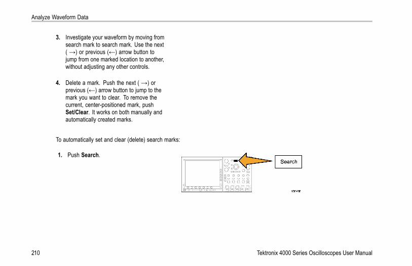
Analyze Waveform Data
3. Investigate your waveform by moving fromsearch mark to search mark. Use the next( →) or previous (←) arrow button tojump from one marked location to another,without adjusting any other controls.
4. Delete a mark. Push the next ( →) orprevious (←) arrow button to jump to themark you want to clear. To remove thecurrent, center-positioned mark, pushSet/Clear. It works on both manually andautomatically created marks.
To automatically set and clear (delete) search marks:
1. Push Search.
210 Tektronix 4000 Series Oscilloscopes User Manual

Analyze Waveform Data
2. Select the search type desired from thelower-bezel menu.
SearchOff
SearchTypeEdge
Source1
Slope Threshold0.00V
The search menu is similar to the trigger menu.
3. From the side-bezel menu, turn on the search.
4. On the screen, hollow triangles show thelocation of automatic marks and solid trianglesshow the custom (user-defined) locations.These appear on both normal and zoomedwaveform views.
5. You can quickly investigate your waveform bymoving from search mark to search mark withthe next ( →) and previous (←) arrow buttons.No other adjustments are needed.
Tektronix 4000 Series Oscilloscopes User Manual 211

Analyze Waveform Data
Quick Tips.
You can copy trigger settings to search for other locations in your acquired waveform that meet the trigger conditions.
You can also copy search settings to your trigger.
Custom (User) marks are saved with the waveform when the waveform is saved and when the setup is saved.
Automatic search marks are not saved with the waveform when the waveform is saved. However, you can easily recapturethem by reusing the search function.
The search criteria are saved in the saved setup.
The Wave Inspector includes the following search capabilities:
Search DescriptionEdge Searches for edges (rising or falling) with a user-specified threshold level.Pulse Width Searches for positive or negative pulse widths that are >, <, =, or ≠ a user specified pulse width.Runt Searches for positive or negative pulses that cross one amplitude threshold but fail to cross a
second threshold before crossing the first again. Search for all runt pulses or only those with aduration >, <, =, or ≠ a user specified time.
Logic Search for a logic pattern (AND, OR, NAND, or NOR) across multiple waveforms with each inputset to either High, Low, or Don’t Care. Search for when the event goes true, goes false, orstays valid for >, <, =, or ≠ a user specified time. Additionally, you can define one of the inputsas a clock for synchronous (state) searches.
Setup & Hold Search for violations of user specified Setup and Hold times.
212 Tektronix 4000 Series Oscilloscopes User Manual

Analyze Waveform Data
Search DescriptionRise/Fall Time Search for rising and/or falling edges that are >, <, =, or ≠ a user specified time.Bus Parallel: Search for a binary or hex value (MSO4000 series only).
I2C: Search for Start, Repeated Start, Stop, Missing Ack, Address, Data, or Address and Data.SPI: Search for SS Active, MOSI, MISO, or MOSI & MISOCAN: Search for Start of Frame, Type of Frame (Data, Remote, Error, Overload), Identifier(standard or extended), Data, Identifier and Data, End of Frame, or Missing Ack.RS-232: Search for Tx Start Bit, Rx Start Bit, Tx End of Packet, Rx End of Packet, Tx Data, orRx Data.
Tektronix 4000 Series Oscilloscopes User Manual 213
Save and Recall Information
Save and Recall InformationThe oscilloscope provides permanent storage for setups, waveforms, and screen images. Use the internal storage of theoscilloscope to save setup files and reference waveform data.
Use external storage, such as CompactFlash media and USB flash drives, to save setups, waveforms, and screen images. Use theexternal storage to carry data to remote computers for further analysis and for archiving.
External File Structure. If you are saving information to external storage, select the appropriate menu (such as the To Fileside-bezel menu to save setups and waveforms) and turn multipurpose knob a to scroll through the external file structure.
D: is the CompactFlash card
E: is the USB flash drive plugged into the USB port on the front of the oscilloscope
F: and G: are the USB flash drives plugged into the USB ports on the rear of the oscilloscope
Use multipurpose knob a to scroll through the list of files. Use the Select front panel button to open and close folders.
Naming Your File. The oscilloscope gives all files it creates a default name in the following format:
tekXXXXX.set for setup files where XXXXX is an integer from 00000 to 99999
tekXXXXX.png, tekXXXXX.bmp, or tekXXXXX. tif for image files
tekXXXXYYY.csv for spreadsheet files or tekXXXXYYY.isf for internal format files
For waveforms, the XXXX is an integer from 0000 to 9999. The YYY is the channel of the waveform, and can be one of the following:
CH1, CH2, CH3, or CH4 for the analog channels
D00, D01, D02, D03, and so on through D15 for the digital channels
214 Tektronix 4000 Series Oscilloscopes User Manual

Save and Recall Information
MTH for a math waveform
RF1, RF2, RF3, or RF4 for reference memory waveforms
ALL for a single spreadsheet file containing multiple channels when you select Save All Waveforms
NOTE. Only analog channels and waveforms derived from analog channels (such as math and reference) can be saved to an ISFfile. When saving all channels in ISF format, a group of files will be saved. Each will have the same value for XXXX, but the YYYvalues will be set to the different channels that were turned on when the Save All Waveforms was performed.
For example, the first time you save a file, that file is named tek00000. The next time you save the same type of file, the file willbe named tek00001.
Editing File, Directory, Reference Waveform, or Instrument Setup Names. Give files descriptive names that you canrecognize at a later date. To edit file names, directory names, reference waveform and instrument setup labels:
1. Push Save / Recall Menu.
Tektronix 4000 Series Oscilloscopes User Manual 215

Save and Recall Information
2. Push Save Screen Image, Save Waveform,or Save Setup.
SaveScreenImage
SaveWaveform
Save Setup RecallWaveform
RecallSetup
Assign
Save| toSetup
File Utilities
3. For waveform or setup files, enter the filemanager by pushing the side-bezel menu ToFile item.
To File
4. Turn multipurpose knob a to scroll through thefile structure. (See page 214, External FileStructure.)
216 Tektronix 4000 Series Oscilloscopes User Manual

Save and Recall Information
5. Push Select to open or close file folders.
6. Push Edit File Name.Edit the file name the same way you editlabels for channels. (See page 82, LabelingChannels and Buses.)
7. Push the Menu Off button to cancel the saveoperation, or push a side-bezel menu OKSave item to complete the operation.
OK Save
Tektronix 4000 Series Oscilloscopes User Manual 217

Save and Recall Information
Saving a Screen ImageA screen image consists of a graphical image of the oscilloscope screen. This is different from waveform data, which consists ofnumeric values for each point in the waveform. To save a screen image:
1. Push Save / Recall Menu.Do not yet push the Save button.
2. Push Save Screen Image from the lower-bezelmenu.
SaveScreenImage
SaveWaveform
Save Setup RecallWaveform
RecallSetup
Assign
Save| toSetup
File Utilities
SaveScreenImage
3. From the side-bezel menu, push File Formatrepeatedly to select among: .tif, .bmp, and.png formats.
File Format.png
218 Tektronix 4000 Series Oscilloscopes User Manual

Save and Recall Information
4. Push Orientation to select between savingthe image in a landscape (horizontal) and aportrait (vertical) orientation.
Orientation
5. Push Ink Saver to turn the Ink Saver mode onor off. When on, this mode provides a whitebackground.
Ink Saver
On |Off
6. Push Edit File Name to create a custom namefor the screen image file. Skip this step to usea default name.
Edit FileName
7. Push OK Save Screen Image to write theimage to the selected media.
OK SaveScreenImage
Tektronix 4000 Series Oscilloscopes User Manual 219

Save and Recall Information
For information on printing screen images of waveforms, go to Printing a Hard Copy. (See page 229, Printing a Hard Copy.)
Saving and Recalling Waveform DataWaveform data consists of the numeric values for each point in the waveform. It copies the data, as opposed to a graphical imageof the screen. To save the current waveform data or to recall previously stored waveform data:
1. Push Save / Recall Menu.
2. Push Save Waveform or Recall Waveformfrom the lower-bezel menu.
NOTE. The oscilloscope can save digitalwaveforms to .csv files, not reference memories.The oscilloscope cannot recall digital waveforms.
SaveScreenImage
SaveWaveform
Save Setup RecallWaveform
RecallSetup
Assign
Save| toWaveform
File Utilities
3. Select one waveform or all waveforms.
220 Tektronix 4000 Series Oscilloscopes User Manual

Save and Recall Information
4. From the resulting side-bezel menu, select thelocation to save the waveform data to or torecall it from.Save the information externally to a file ona CompactFlash card or USB flash drive.Alternatively, save the information internally toone of the two reference memory files in theoscilloscope, or one of the four reference fileson 4-channel models.
5. Push To File to save to a CompactFlash cardor USB flash drive.
To File
This brings up the file manager screen. Use itto define a custom file name. Skip this step touse the default name and location.
Tektronix 4000 Series Oscilloscopes User Manual 221

Save and Recall Information
Saving a Waveform to File. When you push the To File side-bezel menu button, the oscilloscope changes the side-bezel menucontents. The following table describes these side-bezel menu items for saving data to a mass storage file.
Side-bezel menu button DescriptionInternal File Format (.ISF) Sets the oscilloscope to save waveform data from analog channels (and math and reference
waveforms derived from analog channels), in internal waveform save file (.isf) format. This formatis the fastest to write and creates the smallest-sized file. Use this format if you intend to recall awaveform to reference memory for viewing or measuring.The oscilloscope cannot save digital waveforms in an .isf file format.
Spreadsheet File Format(.CSV)
Sets the oscilloscope to save waveform data as a comma-separated data file compatible withpopular spreadsheet programs. This file cannot be recalled to reference memory.
Saving an Analog Waveform to Reference Memory. To save an analog waveform to nonvolatile memory inside theoscilloscope, select the waveform that you want to save, push the Save Waveform screen button, and then select one of thereference waveform locations. Four-channel models have four reference locations. Two-channel models have two referencelocations.
Saved waveforms contain only the most recent acquisition. Gray-scale information, if any, is not saved.
NOTE. 10 M reference waveforms are volatile and not saved when the oscilloscope power is turned off. To keep these waveforms,save them to external storage.
222 Tektronix 4000 Series Oscilloscopes User Manual

Save and Recall Information
Displaying a Reference Waveform. To display a waveform stored in nonvolatile memory:
1. Push Ref R.
2. Push R1, R2, R3, or R4. (R1) |(On) (R2) |(Off) (R3) |(Off) (R4) |(Off)
Removing a Reference Waveform from the Display. To remove a reference waveform from the display:
1. Push Ref R.
Tektronix 4000 Series Oscilloscopes User Manual 223

Save and Recall Information
2. Push the R1, R2, R3, or R4 lower-bezel buttonto remove the reference waveform from thedisplay.The reference waveform is still in nonvolatilememory and can be displayed again.
(R1) |(On) (R2) |(Off) (R3) |(Off) (R4) |(Off)
Saving and Recalling SetupsSetup information includes acquisition information, such as vertical, horizontal, trigger, cursor, and measurement information. Itdoes not include communications information, such as GPIB addresses. To save the setup information:
1. Push Save / Recall Menu.
224 Tektronix 4000 Series Oscilloscopes User Manual

Save and Recall Information
2. Push Save Setup or Recall Setup from thelower-bezel menu.
SaveScreenImage
SaveWaveform
Save Setup RecallWaveform
RecallSetup
Assign
Save| toSetup
File Utilities
Save Setup
To File
To Setup 1
3. From the resulting side-bezel menu, select thelocation to save the setup to or to recall it from.To save setup information to one of the teninternal setup memories in the oscilloscope,push the appropriate side-bezel button.To save setup information to a CompactFlashor USB file, push the To File button. To Setup 2
To Setup 3
– more –
Tektronix 4000 Series Oscilloscopes User Manual 225

Save and Recall Information
4. If you are saving information to a CompactFlashcard or USB flash drive, turn multipurposeknob a to scroll through the file structure. (Seepage 214, External File Structure.)
Push Select to open or close file folders.
Push the Menu Off button to cancel the saveoperation, or push a side-bezel menu Save toSelected File item to complete the operation.
5. Save the file. Save toSelected
File
226 Tektronix 4000 Series Oscilloscopes User Manual

Save and Recall Information
Quick TipsRecalling the Default Setup. Push the front-panel Default Setup button to initialize the oscilloscope to a known setup. (Seepage 86, Using the Default Setup.)
Saving with One Button PushAfter you have defined the save/recall parameters with the Save/Recall Menu button and menu, you can save files with a singlepush of the Save button. For example, if you have defined the save operation to save waveform data to a USB drive, then eachpush of the Save button will save current waveform data to the defined USB drive.
1. To define the Save button behavior, pushSave/Recall Menu.
2. Push Assign Save to button. SaveScreenImage
SaveWaveform
Save Setup RecallWaveform
RecallSetup
Assign
Save| toSetup
File Utilities
Tektronix 4000 Series Oscilloscopes User Manual 227

Save and Recall Information
3. Push the action to assign to the Save button. AssignSave to
ScreenImage
Waveform
Setup
4. From now on, when you push Save theoscilloscope will perform the action that youjust specified rather than requiring you tonavigate through the menus each time.
228 Tektronix 4000 Series Oscilloscopes User Manual
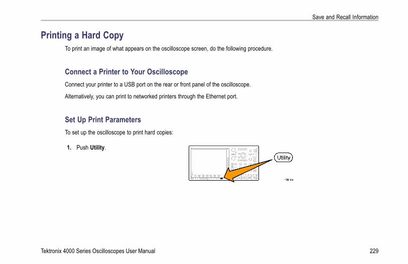
Save and Recall Information
Printing a Hard CopyTo print an image of what appears on the oscilloscope screen, do the following procedure.
Connect a Printer to Your OscilloscopeConnect your printer to a USB port on the rear or front panel of the oscilloscope.
Alternatively, you can print to networked printers through the Ethernet port.
Set Up Print ParametersTo set up the oscilloscope to print hard copies:
1. Push Utility.
Tektronix 4000 Series Oscilloscopes User Manual 229

Save and Recall Information
2. Push Utility Page. Utility Page
3. Turn multipurpose knob a and select PrintSetup.
Print Setup
4. Push Select Printer if you are changing thedefault printer.
Utility PagePrint Setup
SelectPrinter
???
OrientationLandscape
Ink SaverOn
Turn multipurpose knob a to scroll through thelist of available printers.Push Select to choose the desired printer.To add a USB printer to the list, plug theprinter into the USB port. The oscilloscope willautomatically recognize most printers.To add an Ethernet printer to the list, refer tothe next topic. (See page 232, Printing OverEthernet.)
230 Tektronix 4000 Series Oscilloscopes User Manual

Save and Recall Information
5. Select the image orientation (portrait orlandscape).
Landscape
Portrait
6. Choose Ink Saver On or Off.The On selection will print out a copy with aclear (white) background.
Ink Saver on Ink Saver off
Tektronix 4000 Series Oscilloscopes User Manual 231

Save and Recall Information
Printing Over EthernetTo set up the oscilloscope to print over Ethernet:
1. Connect an Ethernet cable to the rear-panelEthernet port.
2. Push Utility.
232 Tektronix 4000 Series Oscilloscopes User Manual

Save and Recall Information
3. Push Utility Page. Utility Page
4. Turn multipurpose knob a and select PrintSetup.
Print Setup
5. Push Select Printer. Utility PagePrint Setup
SelectPrinter
???
OrientationLandscape
Ink SaverOff
Tektronix 4000 Series Oscilloscopes User Manual 233

Save and Recall Information
6. Push Add Network Printer. AddNetworkPrinter
RenamePrinter
DeleteNetworkPrinter
7. Turn multipurpose knob a to scroll through thelist of letters, numbers, and other characters tofind the first character in the printer name thatyou want to enter.If you are using a USB keyboard, use the arrowkeys to position the insertion point and type inthe printer name. (See page 49, Connecting aUSB Keyboard to Your Oscilloscope.)
ABCDEFGHIJKLMNOPQRSTUVWXYZabcdefghijklmnopqrstuvwxyz0123456789_=+-!@#$%^&*()[]<>/~’”\|:,.?
234 Tektronix 4000 Series Oscilloscopes User Manual

Save and Recall Information
8. Push Select or Enter Character to let theoscilloscope know that you have picked theproper character to use.
You can use the lower-bezel buttons to edit thename, as needed.
EnterCharacter
BackSpace
Delete Clear
9. Continue scrolling and pushing Select until youhave entered all the desired characters.
10. Push the down arrow key to move the charactercursor down a row to the Server Name field.
Add Printer
11. Turn multipurpose knob a and push Select orEnter Character as often as needed to enterthe name.
12. If desired, push the down arrow key to movethe character cursor down a row to the ServerIP Address: field.
OK Accept
Tektronix 4000 Series Oscilloscopes User Manual 235

Save and Recall Information
13. Turn multipurpose knob a and push Select orEnter Character as often as needed to enterthe name.
14. When done, push OK Accept.
NOTE. If you have multiple printers connected tothe oscilloscope at the same time, the oscilloscopewill print to the printer listed in the Utility> UtilityPage> Print Setup> Select Printer menu item.
Printing with One Button PushOnce you have connected a printer to your oscilloscope and set up print parameters, you can print current screen images witha single push of a button:
Push the printer icon button in the lower leftcorner of the front panel.
236 Tektronix 4000 Series Oscilloscopes User Manual

Save and Recall Information
Erasing Oscilloscope MemoryYou can erase all setup and waveform information saved in the nonvolatile oscilloscope memory with the TekSecure function. Ifyou have acquired confidential data on your oscilloscope, you may want to execute the TekSecure function before you return theoscilloscope to general use. The TekSecure function:
Replaces all waveforms in all reference memories with null values
Replaces the current front-panel setup and all stored setups with the default setup
Displays a confirmation or warning message, depending on whether the verification is successful or unsuccessful
To use TekSecure:
1. Push Utility.
2. Push Utility Page. Utility Page
Tektronix 4000 Series Oscilloscopes User Manual 237
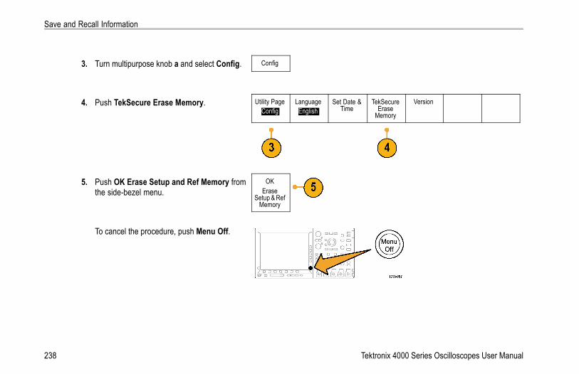
Save and Recall Information
3. Turn multipurpose knob a and select Config. Config
4. Push TekSecure Erase Memory. Utility PageConfig
LanguageEnglish
Set Date &Time
TekSecureErase
Memory
Version
5. Push OK Erase Setup and Ref Memory fromthe side-bezel menu.
OKErase
Setup & RefMemory
To cancel the procedure, push Menu Off.
238 Tektronix 4000 Series Oscilloscopes User Manual

Save and Recall Information
6. Power off the oscilloscope, and then power itback on to complete the process.
Tektronix 4000 Series Oscilloscopes User Manual 239
Using Application Modules
Using Application ModulesOptional application module packages extend the capability of your oscilloscope. (See page 25, Application Module Free Trial.) Youcan install up to four application modules at one time. (See page 25, Installing an Application Module.)
Refer to the Tektronix 4000 Series Oscilloscopes Application Module Installation Instructions that came with your applicationmodule for instructions on installing and testing an application module. Some modules are described in the following list. Additionalmodules may be available. Contact your Tektronix representative or visit our Web site at www.tektronix.com for more information.Also, refer to Contacting Tektronix at the beginning of the manual.
The DPO4EMBD Serial Triggering and Analysis Module adds triggering on packet level information in serial buses used inembedded designs (I2C and SPI), as well as analytical tools to help you efficiently analyze your serial bus. These include digitalviews of the signal, bus views, packet decoding, search tools, and event tables with timestamp information.
The DPO4AUTO Serial Triggering and Analysis Module adds triggering on packet level information in serial buses used inautomotive designs (CAN), as well as analytical tools to help you efficiently analyze your serial bus. These include digital viewsof the signal, bus views, packet decoding, search tools, and event tables with timestamp information.
The DPO4COMP Computer Triggering and Analysis Module adds triggering on byte or packet level information in RS-232,RS-422, RS-485, and UART buses, and analytical tools to help you efficiently analyze your serial bus. These include digitalviews of the signal, bus views, packet decoding, search tools, and event tables with timestamp information.
The DPO4VID Extended Video Module adds triggering on a variety of standard HDTV signals, as well as on custom(non-standard) bilevel and trilevel video signals with 3 to 4,000 lines.
240 Tektronix 4000 Series Oscilloscopes User Manual

Application Examples
Application ExamplesThis section contains ways to use your instrument in both common and advanced troubleshooting tasks.
Taking Simple MeasurementsIf you need to see a signal in a circuit, butyou do not know the signal amplitude orfrequency, connect the probe from channel 1of the oscilloscope to the signal. Then displaythe signal and measure its frequency andpeak-to-peak amplitude.
Tektronix 4000 Series Oscilloscopes User Manual 241

Application Examples
Using AutosetTo quickly display a signal:
1. Push Autoset.
242 Tektronix 4000 Series Oscilloscopes User Manual

Application Examples
The oscilloscope sets vertical, horizontal, and trigger controls automatically. You can manually adjust any of these controls if youneed to optimize the display of the waveform.
When you are using more than one channel, the autoset function sets the vertical controls for each channel and uses thelowest-numbered active channel to set the horizontal and trigger controls.
Selecting Automatic MeasurementsThe oscilloscope can take automatic measurements of most displayed signals. To measure signal frequency and peak-to-peakamplitude:
1. Push Measure.
2. Push Select Measurement. SelectMeasure-
ment(a) 1
RemoveMeasure-
ment
GatingScreen
StatisticsOn
ReferenceLevels
Indicators ConfigureCursors
Tektronix 4000 Series Oscilloscopes User Manual 243

Application Examples
3. Turn multipurpose knob a to select the channelfrom which you want to measure. For example,select channel 1. This step is only neededif you are acquiring data on more than onechannel.
4. Select the Frequency measurement from theside-bezel menu. Frequency
5. Push -more- until you can select the Pk-Pkmeasurement.
-more-
6. Push Menu Off.
244 Tektronix 4000 Series Oscilloscopes User Manual

Application Examples
7. Observe that the measurements appear on thescreen and update as the signal changes.
Tektronix 4000 Series Oscilloscopes User Manual 245

Application Examples
Measuring Two Signals
In this example, you are testing a piece ofequipment and need to measure the gain of itsaudio amplifier. You have an audio generatorthat can inject a test signal at the amplifierinput. Connect two oscilloscope channelsto the amplifier input and output as shown.Measure both signal levels and use thesemeasurements to calculate the gain.
246 Tektronix 4000 Series Oscilloscopes User Manual

Application Examples
To display the signals connected to channels 1 and 2:
1. Push channel 1 and channel 2 to activateboth channels.
2. Push Autoset.
To select measurements for the two channels:
1. Push Measure to see the measurement menu.
Tektronix 4000 Series Oscilloscopes User Manual 247

Application Examples
2. Push Select Measurement. SelectMeasure-
ment(a) 1
RemoveMeasure-
ment
GatingScreen
StatisticsOn
ReferenceLevels
Indicators ConfigureCursors
3. Turn multipurpose knob a to select channel 1.
4. Page through the measurement menus untilyou find Amplitude. Select Amplitude.
Amplitude
248 Tektronix 4000 Series Oscilloscopes User Manual

Application Examples
5. Turn multipurpose knob a to select channel 2.
6. Select Amplitude. Amplitude
7. Calculate the amplifier gain using the followingequations:Gain = (output amplitude ÷ input amplitude) =(3.155 V ÷ 130.0 mV) = 24.27Gain (dB) = 20 x log(24.27) = 27.7 dB
Tektronix 4000 Series Oscilloscopes User Manual 249

Application Examples
Customizing Your Measurements
In this example, you want to verify that theincoming signal to digital equipment meets itsspecifications. Specifically, the transition timefrom a low logic level (0.8 V) to a high logiclevel (2.0 V) must be 10 ns or less.
To select the Rise Time measurement:
1. Push Measure.
250 Tektronix 4000 Series Oscilloscopes User Manual

Application Examples
2. Push Select Measurement. SelectMeasure-
ment(a) 1
RemoveMeasure-
ment
GatingScreen
StatisticsOn
ReferenceLevels
Indicators ConfigureCursors
3. Turn multipurpose knob a to select channel 1.This step is only needed if you are acquiringdata on more channels than just channel 1.
4. Select the Rise Time measurement from theside-bezel menu.
Rise Time
Tektronix 4000 Series Oscilloscopes User Manual 251

Application Examples
5. Push Reference Levels. ReferenceLevels
6. Push Set Levels in to select units. Set Levelsin
% |Units
7. Push High Ref and turn multipurpose knob ato enter 2.00 V. If needed, push Fine to changethe sensitivity of the multipurpose knob.
High Ref(a) 2.00 V
Mid Ref
8. Push Low Ref and turn multipurpose knob a toenter 800 mV. If needed, push Fine to changethe sensitivity of the multipurpose knob.
Low Ref(a) 800 mV
252 Tektronix 4000 Series Oscilloscopes User Manual

Application Examples
Rise time is typically measured between the 10% and 90% amplitude levels of a signal. These are the default reference levelsthat the oscilloscope uses for rise time measurements. However, in this example, you need to measure the time that the signaltakes to pass between the 0.8 V and 2.0 V levels.
You can customize the rise time measurement to measure the signal transition time between any two reference levels. Youcan set each of these reference levels to a specific percent of the signal amplitude or to a specific level in vertical units (suchas volts or amperes).
Measuring Specific Events. Next you want to see the pulses in the incoming digital signal, but the pulse widths vary so it ishard to establish a stable trigger. To look at a snapshot of the digital signal, do this step:
1. Push Single to capture a single acquisition.This assumes that the oscilloscope will triggerwith the current settings.
Now you want to measure the width of eachdisplayed pulse. You can use measurementgating to select a specific pulse to measure.To measure the second pulse:
2. Push Measure.
Tektronix 4000 Series Oscilloscopes User Manual 253

Application Examples
3. Push Select Measurement. Selectmeasure-
ment(a) 1
RemoveMeasure-
ment
GatingScreen
StatisticsOn
ReferenceLevels
Indicators ConfigureCursors
4. Turn multipurpose knob a to select channel 1.
5. Select Positive Pulse Width measurement.PositivePulseWidth
254 Tektronix 4000 Series Oscilloscopes User Manual

Application Examples
6. Push Gating. SelectMeasure-
ment1
RemoveMeasure-
ment
GatingScreen
StatisticsOn
ReferenceLevels
Indicators ConfigureCursors
7. Select Between Cursors from the side-bezelmenu to choose measurement gating usingcursors. Between
Cursors
8. Place one cursor to the left and one cursor tothe right of the second pulse.
Tektronix 4000 Series Oscilloscopes User Manual 255

Application Examples
9. View the resulting width measurement(160 ms) for the second pulse.
256 Tektronix 4000 Series Oscilloscopes User Manual

Application Examples
Analyzing Signal DetailIn this example, you have a noisy signaldisplayed on the oscilloscope, and you needto know more about it. You suspect that thesignal contains much more detail than you cancurrently see in the display.
Tektronix 4000 Series Oscilloscopes User Manual 257

Application Examples
Looking at a Noisy SignalThe signal appears noisy. You suspect that noise is causing problems in your circuit. To better analyze the noise:
1. Push Acquire.
2. Push Mode on the lower-bezel menu. ModeSample
RecordLength
10k
ResetHorizontalPosition
WaveformDisplay
XY DisplayOff
258 Tektronix 4000 Series Oscilloscopes User Manual

Application Examples
3. Push Peak Detect on the side-bezel menu.Sample
PeakDetect
Hi Res
Envelope
Average
4. Push Intensity and turn multipurpose knob ato see the noise more easily.
Tektronix 4000 Series Oscilloscopes User Manual 259

Application Examples
5. View the results on the display. Peak detectemphasizes noise spikes and glitches in yoursignal as narrow as 1 ns, even when the timebase is set to a slow setting.
260 Tektronix 4000 Series Oscilloscopes User Manual

Application Examples
Peak-detect and the other acquisition modes are explained earlier in this manual. (See page 89, Acquisition Concepts.)
Separating the Signal from NoiseNow you want to analyze the signal shape and ignore the noise. To reduce random noise in the oscilloscope display:
1. Push Acquire.
2. Push Mode. ModeSample
RecordLength
10K
ResetHorizontalPosition
WaveformDisplay
XY DisplayOff
3. Push Average on the side-bezel menu.Average
Tektronix 4000 Series Oscilloscopes User Manual 261

Application Examples
Averaging reduces random noise and makes iteasier to see detail in a signal. In the exampleto the right, a ring shows on the rising and fallingedges of the signal when the noise is removed.
262 Tektronix 4000 Series Oscilloscopes User Manual

Application Examples
Taking Cursor MeasurementsYou can use the cursors to take quick measurements on a waveform. To measure the ring frequency at the rising edge of the signal:
1. Push channel 1 to select the channel 1 signal.
2. Push Measure.
3. Push Configure Cursors. SelectMeasure-
ment1
RemoveMeasure-
ment
GatingScreen
StatisticsOn
ReferenceLevels
Indicators ConfigureCursors
Tektronix 4000 Series Oscilloscopes User Manual 263

Application Examples
4. Push Vertical Bar Units repeatedly to selectHz (1/s).
Vertical BarUnits
Hz (1/s)
5. Push Cursors repeatedly until the two verticalbar cursors appear on the selected waveform.
6. Place one cursor on the first peak of the ringusing multipurpose knob a.
7. If the cursor readout says that the cursors arelinked, push Select to unlink them.
264 Tektronix 4000 Series Oscilloscopes User Manual
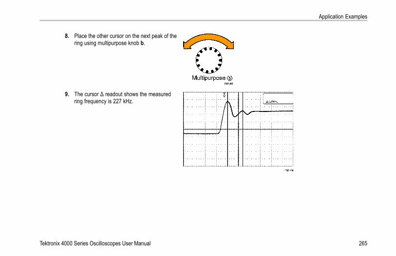
Application Examples
8. Place the other cursor on the next peak of thering using multipurpose knob b.
9. The cursor Δ readout shows the measuredring frequency is 227 kHz.
Tektronix 4000 Series Oscilloscopes User Manual 265

Application Examples
Triggering on a Video SignalThe oscilloscope supports triggering on NTSC, SECAM, and PAL signals.
In this example, you are testing the video circuitin a piece of medical equipment and need todisplay the video output signal. The videooutput is an NTSC standard signal. Use thevideo signal to obtain a stable display.
To trigger on the video fields:
1. Push Trigger Menu.
266 Tektronix 4000 Series Oscilloscopes User Manual

Application Examples
2. Push Type. Type
3. Turn multipurpose knob a to scroll through thetrigger type side menu until you select Video.
Video
4. Push Video Standard, and turn multipurposeknob a to scroll through the standards until youselect 525/NTSC.
TypeVideo
VideoStandard
525/NTSC
Source1
Trigger OnAll Lines
ModeAuto
& Holdoff
5. Push Trigger On.
6. Select Odd Fields. Odd Fields
If the signal had been noninterlaced, you couldchoose to trigger on All Fields.
Tektronix 4000 Series Oscilloscopes User Manual 267

Application Examples
7. Turn the Horizontal Scale knob to see acomplete field across the screen.
8. View results.
268 Tektronix 4000 Series Oscilloscopes User Manual

Application Examples
Triggering on LinesTriggering on Lines. To look at the video lines in the field:
1. Push Trigger Menu.
2. Push Type. Type
3. Turn multipurpose knob a to scroll through thetrigger type side menu until you select Video.
Video
Tektronix 4000 Series Oscilloscopes User Manual 269

Application Examples
TypeVideo
VideoStandard
525/NTSC
Source1
Trigger OnAll Lines
ModeAuto
& Holdoff
4. Push Trigger On.
5. Select All Lines.To trigger on a specific line, select LineNumber, and use multipurpose knob a toselect the line number.
All Lines
6. Adjust Horizontal Scale to see a completevideo line across the screen.
270 Tektronix 4000 Series Oscilloscopes User Manual

Application Examples
7. Observe the results.
Capturing a Single-Shot SignalIn this example, the reliability of a reed relay in a piece of equipment has been poor, and you need to investigate the problem.You suspect that the relay contacts arc when the relay opens. The fastest you can open and close the relay is about once perminute, so you need to capture the voltage across the relay as a single-shot acquisition.
To set up for a single-shot acquisition:
1. Adjust the Vertical Scale and Horizontal Scale to appropriate ranges for the signal you expect to see.
Tektronix 4000 Series Oscilloscopes User Manual 271
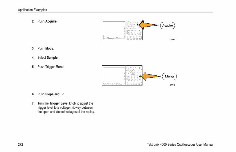
Application Examples
2. Push Acquire.
3. Push Mode.
4. Select Sample.
5. Push Trigger Menu.
6. Push Slope and .
7. Turn the Trigger Level knob to adjust thetrigger level to a voltage midway betweenthe open and closed voltages of the replay.
272 Tektronix 4000 Series Oscilloscopes User Manual

Application Examples
8. Push Single (single sequence).
When the relay opens, the oscilloscopetriggers and captures the event.The Single sequence button disables autotriggering so that only a valid triggeredsignal is acquired.
Tektronix 4000 Series Oscilloscopes User Manual 273

Application Examples
Optimizing the Acquisition
The initial acquisition shows the relay contactbeginning to open at the trigger point. This isfollowed by large spikes that indicate contactbounce and inductance in the circuit. Theinductance can cause contact arcing andpremature relay failure.Before you take the next acquisition, you canadjust the vertical and horizontal controls togive you a preview of how the next acquisitionmight appear. As you adjust these controls, thecurrent acquisition is repositioned, expanded,or compressed. This preview is useful tooptimize the settings before the next single-shotevent is captured.When the next acquisition is captured withthe new vertical and horizontal settings, youcan see more detail about the relay contactopening. You can now see that the contactbounces several times as it opens.
274 Tektronix 4000 Series Oscilloscopes User Manual

Application Examples
Using the Horizontal Zoom FunctionTo take a close look at a particular point on the acquired waveform, use the horizontal zoom function. To look closely at thepoint where the relay contact first begins to open:
1. Turn the Zoom knob.
2. Turn the Pan knob to place the center ofthe zoom box close to where the relaycontact begins to open.
3. Turn the Zoom knob to magnify thewaveform in the zoom window.
Tektronix 4000 Series Oscilloscopes User Manual 275

Application Examples
The ragged waveform and the inductive load inthe circuit suggest that the relay contact maybe arcing as it opens.
Correlating Data with a TLA5000 Logic AnalyzerTo troubleshoot designs with fast clock edges and data rates, it helps to view analog characteristics of digital signals in relation tocomplex digital events in the circuit. You can do that with iView, which lets you transfer analog waveforms from the oscilloscopeto the logic analyzer display. You can then view time-correlated analog and digital signals side-by-side, and use this to pinpointsources of glitches and other problems.
NOTE. Digital waveforms from 4000 series oscilloscopes cannot be transferred to the logic analyzer display.
276 Tektronix 4000 Series Oscilloscopes User Manual

Application Examples
The iView External Oscilloscope Cable allows you to connect your logic analyzer to a Tektronix oscilloscope. This enablescommunication between the two instruments. For 4000 series oscilloscopes, you also need a TEK-USB-488 adaptor. The AddExternal Oscilloscope wizard, which is available from the TLA application System menu, guides you through the process ofconnecting the iView cable between your logic analyzer and oscilloscope.
The TLA also provides a setup window to assist you in verifying, changing, and testing the oscilloscope settings. Before acquiringand displaying a waveform, you must establish a connection between your Tektronix logic analyzer and oscilloscope using theAdd External Oscilloscope wizard.
Tektronix 4000 Series Oscilloscopes User Manual 277

Application Examples
To do this:
1. Select Add iView External Oscilloscopefrom the logic analyzer System menu.
278 Tektronix 4000 Series Oscilloscopes User Manual

Application Examples
2. Select your model of oscilloscope.
3. Follow the on-screen instructions, and thenclick Next.
4. See your Tektronix Logic Analyzerdocumentation for more information oncorrelating data between your Tektronixoscilloscope and logic analyzer.
Tektronix 4000 Series Oscilloscopes User Manual 279
Application Examples
Tracking Down Bus AnomaliesIn this example, you are testing your new I2C circuit. Something is not working. You tell the master IC to send a message to theslave IC. Then you expect to receive data back and an LED to light. The light never goes on. Where in the ten or so commands thatwere sent out did the problem occur? Once you locate the problem location, how do you determine what went wrong?
You can use your oscilloscope, with its serial triggering and long-record length management features, to track down the problem inboth the physical layer and in the protocol layer of the bus.
Basic StrategyFirst, you will display and acquire the bus signal by setting up the bus parameters and trigger. Then, you will search through eachpacket with the search/mark functions.
NOTE. Triggering on I2C, SPI, CAN, and RS-232 bus signals requires use of the DPO4EMBD. DPO4AUTO, or DPO4COMP SerialTriggering and Analysis Module. Triggering on Parallel bus signals requires use of the MSO4000 series.
280 Tektronix 4000 Series Oscilloscopes User Manual

Application Examples
1. Connect the channel 1 probe to the clock line.
2. Connect the channel 2 probe to the data line.
3. Push Autoset.
Tektronix 4000 Series Oscilloscopes User Manual 281

Application Examples
4. Push the B1 button and enter the parametersof your I2C bus in the resulting screen menus.
5. Push Trigger Menu.
6. Push Type to select Bus. Enter triggerparameters in the resulting screen menus.
TypeBus
Source BusB1 (I2C)
Trigger OnAddress
Address07F
DirectionRead
ModeAuto
& Holdoff
282 Tektronix 4000 Series Oscilloscopes User Manual

Application Examples
7. Analyze the physical layer. For example, youcan use the cursors for manual measurements.(See page 185, Taking Manual Measurementswith Cursors.) You can also use the automatedmeasurements. (See page 168, TakingAutomatic Measurements.)
8. Push Search. Set Search Marks to On. Entera search type, source, and other parametersas relevant on the lower-bezel menu andassociated side-bezel menus. (See page 203,Using Wave Inspector to Manage Long RecordLength Waveforms.)
9. Jump ahead to the next search point bypushing the right arrow key. Push it again andagain until you see all the events. Jump backwith the left arrow key. Do you have all thepackets that you expected to have? If not, atleast you have narrowed your search down tothe last packet sent.
Tektronix 4000 Series Oscilloscopes User Manual 283
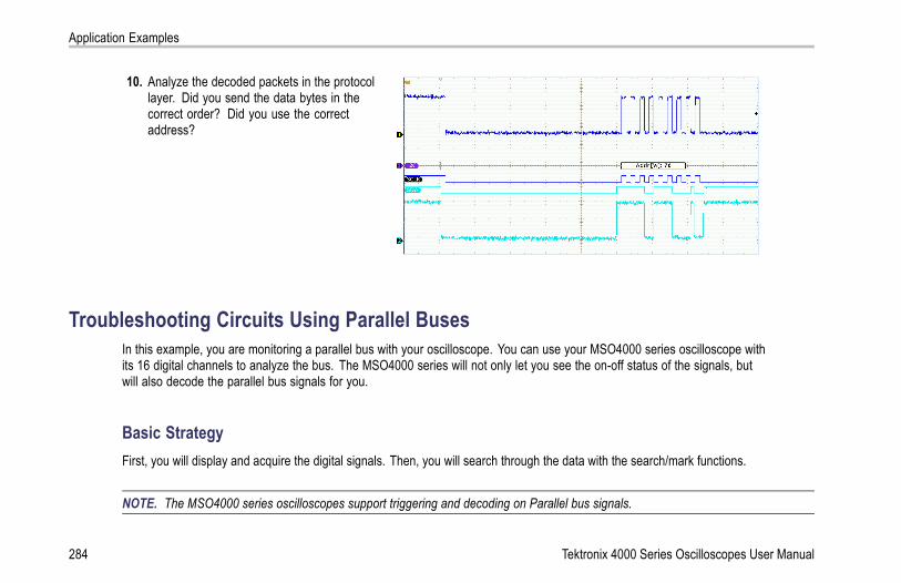
Application Examples
10. Analyze the decoded packets in the protocollayer. Did you send the data bytes in thecorrect order? Did you use the correctaddress?
Troubleshooting Circuits Using Parallel BusesIn this example, you are monitoring a parallel bus with your oscilloscope. You can use your MSO4000 series oscilloscope withits 16 digital channels to analyze the bus. The MSO4000 series will not only let you see the on-off status of the signals, butwill also decode the parallel bus signals for you.
Basic StrategyFirst, you will display and acquire the digital signals. Then, you will search through the data with the search/mark functions.
NOTE. The MSO4000 series oscilloscopes support triggering and decoding on Parallel bus signals.
284 Tektronix 4000 Series Oscilloscopes User Manual

Application Examples
1. Connect the desired logic probe tips to thedesired test points. For simplicity, this exampleconnects to a 7-bit counter.
2. Push Default Setup. Then push the channel1 button to remove the waveform from thedisplay.
Tektronix 4000 Series Oscilloscopes User Manual 285

Application Examples
3. Push the D15-D0 button.
4. Push the D15-D0 On/Off lower-bezel buttonand then push the Turn On D7-D0 side-bezelto display the digital waveforms. To turn off achannel, use multipurpose knob a to selectthe channel and push the Display side-bezelto select Off.
5. Push Autoset.
6. Push the B1 button, select Parallel as the bustype. Push the lower-bezel Define Inputs andenter the parameters for your bus for ClockedData, Clock Edge, the Number of Bits, andDefine Bits.
286 Tektronix 4000 Series Oscilloscopes User Manual

Application Examples
7. Turn the Horizontal Scale knob to adjust thetimebase.As you increase the time per division, you willsee more data appear in the Bus display.
8. Push Trigger Menu. Push Type, select Bus,and enter the parameters of the trigger, suchas the Source Bus and Data. Define the Modeand Holdoff as desired.
9. Push Search, push the Search lower-bezelbutton, and select On in the side-bezel menu.
10. Push Search Type. Use the multipurposeknob a to select Bus and then push Data. Usethe multipurpose knobs a and b to define thedata value.
Tektronix 4000 Series Oscilloscopes User Manual 287

Application Examples
11. Push the Previous and Next Mark buttons tonavigate through the record.
12. Push Zoom, and Pan to the areas of interestto analyze the results.
288 Tektronix 4000 Series Oscilloscopes User Manual

Application Examples
Troubleshooting an RS-232 BusIn this example, you are looking at analog characteristics of a digital signal in a digital circuit. You are doing this to analyze thesignal integrity of a signal. For example, you might be testing RS-232 bus signals.
You can use your MSO4000 series oscilloscope, with its 2 or 4 analog channels and 16 digital channels to track down the problem.It will even decode your RS-232 signals into ASCII characters.
Basic StrategyFirst, you will display and acquire the digital signal. Then, you will look at both the analog and digital representations of the signal.Finally, you will search through each RS-232 byte with the search/mark functions.
NOTE. Triggering on RS-232 bus signals requires use of the DPO4COMP Serial Triggering and Analysis Module. (See page 25,Application Module Free Trial.)
Tektronix 4000 Series Oscilloscopes User Manual 289

Application Examples
1. Connect the desired analog probe tip to thedesired test point.
2. Push Default Setup.
290 Tektronix 4000 Series Oscilloscopes User Manual

Application Examples
3. Push Autoset.
4. Push B1.
5. Push the Bus B1 lower-bezel button, usemultipurpose knob a to select RS-232, andenter the parameters of the bus in the resultingscreen menus.
6. Push the Bus Display lower-bezel button,push the Bus and Waveforms side-bezelbutton, and push the ASCII side-bezel.
7. Turn the Horizontal Scale knob to adjust thetimebase.As you increase the time per division, you willsee more data appear in the Bus display.
Tektronix 4000 Series Oscilloscopes User Manual 291

Application Examples
8. Push Trigger Menu. Select the Bus triggertype. Define what type of condition to triggeron, such as the Tx Start Bit.
9. Push Search, push the Search lower-bezelbutton, and select On in the side-bezel menu.
10. Push Search Type. Use multipurpose knob ato select Bus. Push Search For and selectthe desired search, such as for the Tx Start Bit.
292 Tektronix 4000 Series Oscilloscopes User Manual

Application Examples
11. Push the Previous and Next Mark buttons tonavigate through the record.
12. Push Zoom and Pan to see the areas ofinterest and analyze the results.
Tektronix 4000 Series Oscilloscopes User Manual 293

Application Examples
294 Tektronix 4000 Series Oscilloscopes User Manual

Appendix: Warranted Specifications, Safety Certifications, and Electromagnetic Compatibility
Appendix: Warranted Specifications, Safety Certifications, andElectromagnetic Compatibility
The limits stated below are for ambient temperature of ≤30 °C and the bandwidth selection set to FULL.Reduce the upper bandwidth frequency by 1% for each °C above 30 °C.Instrument 5 mV/div to 1 V/div 2 mV/div to 4.98 mV/div 1 mV/div to
1.99 mV/divDPO/MSO4104 DC to 1 GHz DC to 350 MHz DC to 200 MHzDPO/MSO4054 DC to 500 MHz DC to 350 MHz DC to 200 MHz
Instrument 2 mV/div to 1 V/div 1 mV/div to 1.99 V/divDPO/MSO4034 DC to 350 MHz DC to 200 MHz
Analog bandwidth,50 Ω
DPO/MSO4032 DC to 350 MHz DC to 200 MHzInput impedance, DCcoupled
1 MΩ ±1% in parallel with 13 pF ±2 pF50 Ω ±1%DPO/MSO4101: VSWR ≤ 1.5:1 from DC to 1 GHz, typicalDPO/MSO4054: VSWR ≤ 1.5:1 from DC to 500 MHz, typicalDPO/MSO4034, DPO/MSO4032: VSWR ≤ 1.5:1 from DC to 350 MHz, typical
Tektronix 4000 Series Oscilloscopes User Manual 295

Appendix: Warranted Specifications, Safety Certifications, and Electromagnetic Compatibility
DC Balance 0.2 div with the input DC-50 Ω coupled and 50 Ω terminated0.25 div at 2 mV/div with the input DC-50 Ω coupled and 50 Ω terminated0.5 div at 1 mV/div with the input DC-50 Ω coupled and 50 Ω terminated0.2 div with the input DC-1 MΩ coupled and 50 Ω terminated0.3 div at 1 mV/div with the input DC-1 MΩ coupled and 50 Ω terminated
DC gain accuracy For 1 MΩ path:±1.5%, derated at 0.100%/°C above 30 °C±3.0% Variable Gain, derated at 0.100%/°Cabove 30 °C
For 50 Ω path:±1.5%, derated at 0.050%/°C above 30 °C±3.0% Variable Gain, derated at 0.050%/°Cabove 30 °C
Offset accuracy ±[0.005 × | offset – position | + DC Balance]
NOTE. Both the position and constant offset term must be converted to volts by multiplying by theappropriate volts/div term.
Long-term samplerate and delay timeaccuracy
±5 ppm over any ≥ 1 ms time interval.
296 Tektronix 4000 Series Oscilloscopes User Manual
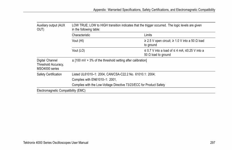
Appendix: Warranted Specifications, Safety Certifications, and Electromagnetic Compatibility
LOW TRUE; LOW to HIGH transition indicates that the trigger occurred. The logic levels are givenin the following table:Characteristic LimitsVout (HI) ≥ 2.5 V open circuit; ≥ 1.0 V into a 50 Ω load
to ground
Auxiliary output (AUXOUT)
Vout (LO) ≤ 0.7 V into a load of ≤ 4 mA; ≤0.25 V into a50 Ω load to ground
Digital ChannelThreshold Accuracy,MSO4000 series
± [100 mV + 3% of the threshold setting after calibration]
Safety Certification Listed UL61010–1: 2004, CAN/CSA-C22.2 No. 61010.1: 2004;Complies with EN61010–1: 2001,Complies with the Low-Voltage Directive 73/23/ECC for Product Safety
Electromagnetic Compatibility (EMC)
Tektronix 4000 Series Oscilloscopes User Manual 297
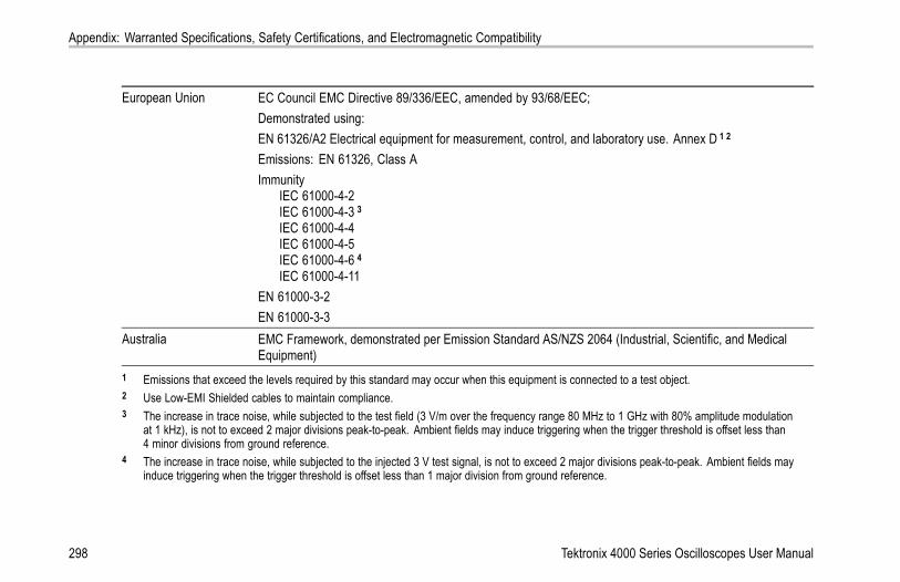
Appendix: Warranted Specifications, Safety Certifications, and Electromagnetic Compatibility
European Union EC Council EMC Directive 89/336/EEC, amended by 93/68/EEC;Demonstrated using:EN 61326/A2 Electrical equipment for measurement, control, and laboratory use. Annex D 1 2
Emissions: EN 61326, Class AImmunity
IEC 61000-4-2IEC 61000-4-3 3
IEC 61000-4-4IEC 61000-4-5IEC 61000-4-6 4
IEC 61000-4-11EN 61000-3-2EN 61000-3-3
Australia EMC Framework, demonstrated per Emission Standard AS/NZS 2064 (Industrial, Scientific, and MedicalEquipment)
1 Emissions that exceed the levels required by this standard may occur when this equipment is connected to a test object.2 Use Low-EMI Shielded cables to maintain compliance.3 The increase in trace noise, while subjected to the test field (3 V/m over the frequency range 80 MHz to 1 GHz with 80% amplitude modulation
at 1 kHz), is not to exceed 2 major divisions peak-to-peak. Ambient fields may induce triggering when the trigger threshold is offset less than4 minor divisions from ground reference.
4 The increase in trace noise, while subjected to the injected 3 V test signal, is not to exceed 2 major divisions peak-to-peak. Ambient fields mayinduce triggering when the trigger threshold is offset less than 1 major division from ground reference.
298 Tektronix 4000 Series Oscilloscopes User Manual

Index
IndexSymbols and Numbers50 Ω protection, 160
AAccessories, 1Acquire button, 55, 94, 147, 258, 261Acquisition
input channels and digitizers, 89modes defined, 92readout, 67sampling, 89
AdapterTEK-USB-488, 5TPA-BNC, 5, 13
Adding waveform, 146Advanced math, 198Altitude
DPO4000 and MSO4000, 8P6139A, 10P6516, 11
Amplitude measurement, 174Analysis and connectivity, xiiApplication modules, xiii, 25, 240
30-day free trial, 25DPO4AUTO, 4, 98DPO4COMP, 4, 98DPO4EMBD, 4, 98DPO4VID, 4, 131
Area measurement, 176Attenuation, 159Auto trigger mode, 118Autoset, 87, 242
Video, 88Autoset button, 21, 55, 62, 80, 87, 242Autoset undo, 88Aux In connector, 75Auxiliary readout, 72Average acquisition mode, 93
BB trigger, 144B1 / B2 / B3 / B4 button, 57, 98, 99,
132Backlight intensity, 152Bandwidth, x, 157Baseline indicators, 73Before Installation, 1
Blackman-Harris FFT window, 198Blue lines, 167BNC interface, 14Burst Width measurement, 172Bus
button, 98, 99, 132display, 74, 106, 107menu, 57, 100positioning and labeling, 161setup, 99
Bus and Waveforms display, 106show physical layer bus
activity, 109Bus trigger, defined, 131Buses, 98, 132
cursor readout, 189Button
Acquire, 55, 94, 147, 258, 261Autoset, 21, 55, 62, 80, 87, 242B1 / B2, 57B1 / B2 / B3 / B4, 98, 99, 132bus, 98, 99, 132Channel, 56Cursors, 58, 185, 264
Tektronix 4000 Series Oscilloscopes User Manual 299

Index
D15 - D0, 65, 115Default Setup, 64, 80, 86Fine, 54, 58, 59, 60, 61, 63Force Trig, 62, 119hard copy, 63, 236Intensity, 152M, 57, 191, 194Math, 57, 191, 194Measure, 55, 168, 179, 180,
243, 247, 250, 253Menu Off, 65, 244Next, 61Play-pause, 60, 207Previous, 60Print, 63printer, 236Ref, 57, 201, 223Run/Stop, 62, 97, 145Save / Recall, 56, 64, 218Search, 55, 210Select, 59, 264Set / Clear Mark, 61, 209Set to 50%, 62, 123Single, 62, 145, 253, 273Test, 55Trigger, 55Trigger level, 62
Trigger menu, 124, 266Utility, 26, 29, 32, 56, 149, 151,
229Vertical, 56Zoom, 60
byte matching, 139
CCalibration, 31, 33Calibration certificate, 2CAN, 57, 98, 132CAN trigger, 138Channel button, 56Channel readout, 72Channel vertical menu, 156Cleaning, 12Clearance, DPO4000 and
MSO4000, 7Communications, 41, 46CompactFlash, x, 2, 5, 56, 64, 214Compensate probe, 22Compensate signal path, 31Confidential data, 237Connecting a USB keyboard, 49Connecting to a PC, 41Connectivity, 2, 41, 46
Connectorsfront-panel, 75rear-panel, 77side-panel, 76
Controls, 51Coupling, 156Coupling, trigger, 120Cover, front, 2Cross Hair graticule style, 150CSV format, 222Cursor readout, 69, 189Cursors, 185
button, 58, 185, 264linking, 186measurements, 185menu, 185XY, 191
Cycle Area measurement, 176Cycle Mean measurement, 175Cycle RMS measurement, 175
DD15 - D0 button, 65, 115Date and time, changing, 29Default Setup, 86, 227
button, 64, 80, 86
300 Tektronix 4000 Series Oscilloscopes User Manual

Index
menu, 64Undo, 87
Delay measurement, 171Delayed trigger, 142Depth, DPO4000 and MSO4000, 7Deskew, 159Digital channels, 167
Baseline indicators, 73Group icon, 74scaling, positioning, grouping,
and labeling, 163setup, 110
Digital probe interface, 14Display
information, 66persistence, 147style, 147XY, 148, 149
Displaying, reference waveforms, 223Documentation, xiiDPO4AUTO, 4, 98DPO4COMP, 4, 98DPO4EMBD, 4, 98DPO4VID, 4, 131Drivers, 41, 44Dual waveform math, 191
Ee*Scope, 46Edge trigger, defined, 126Edges
Fuzzy, 167White, 167
Envelope acquisition mode, 93Erase setup and ref memory, 237Ethernet, xi, 44, 46, 47
port, 77printing, 232
Event Table, 107, 108Excel, 41Expansion point, 92Expansion point icon, 68
FFactory calibration, 33Fall Time measurement, 171FFT
Blackman-Harris, 198controls, 194Hamming, 197Hanning, 198Rectangular, 197
File format, 218
Internal File Format (ISF), 222Spreadsheet file format
(.CSV), 222File names, 214File system, 214, 222Fine, 59Fine button, 54, 58, 60, 61, 63Firmware upgrade, 34firmware.img file, 34Force Trig button, 62, 119Frame graticule style, 150Frequency measurement, 171Frequency, Input power
DPO4000 and MSO4000, 7Front cover, 2Front panel, 51Front-panel connectors, 75Front-panel overlay, 28Full graticule style, 150Functional check, 19Fuzzy edges, 167
GGating, 177GPIB, 42, 78GPIB address, 44
Tektronix 4000 Series Oscilloscopes User Manual 301

Index
GraticuleCross Hair, 150Frame, 150Full, 150Grid, 150intensity, 152IRE, 151mV, 151styles, 149
Green lines, 167Grid graticule style, 150Ground, 16Ground lead, 24Ground strap, 16Ground strap connector, 76Ground yourself to discharge static, 16Group icon, 74Grouping channels, 113
digital, 163
HHamming FFT window, 197Hanning FFT window, 198Hard copy, 229Hard copy button, 63Height, DPO4000 and MSO4000, 7
Hi Res acquisition mode, 93High measurement, 174High-low indicators, 73Holdoff, trigger, 119Horizontal delay, 120Horizontal lines
Green and blue, 167Horizontal position, 61, 92, 120, 121,
154, 197, 275and math waveforms, 193defined, 81readout, 71
Horizontal scale, 61, 154, 197, 268,270, 271, 275and math waveforms, 193defined, 81readout, 71
How tocompensate a voltage probe, 22compensate the signal path, 31connect probes and adapters, 12connect to a computer, 41erase memory, 237label channels and buses, 82manage long record length
waveforms, 203perform a functional check, 19
power off the oscilloscope, 18power on the oscilloscope, 16print a hard copy, 229recall setups, 224recall waveforms, 218save screen images, 218save setups, 224save waveforms, 218search through and add marks to
waveforms, 209select a trigger, 126select automatic measure-
ments, 171setup analog channels, 79setup bus parameters, 99setup digital channels, 110setup input parameters, 156setup VISA communications, 41take automatic measure-
ments, 168take manual measurements with
cursors, 185trigger on buses, 132upgrade the firmware, 34use a sequential trigger, 142use e*Scope, 46use MagniVu, 115
302 Tektronix 4000 Series Oscilloscopes User Manual

Index
use Wave Inspector, 203Humidity
DPO4000 and MSO4000, 8P6139A, 10P6516, 12
II2C, 57, 98, 132
trigger, 135Icon
Expansion point, 68Trigger level, 70Trigger position, 68
Image orientation, 219, 231Impedance, 157Indicator, waveform baseline, 73Infinite persistence, 149Ink Saver, 219, 231Inner knob, 60, 193Input capacitance, P6516, 11Input resistance, P6516, 11Installing, Application modules, xiiiIntensity button, 152Internal File Format (ISF), 222Invert, 157IRE graticule, 151
ISF format, 222
KKeyboard, USB, 49Knob
inner, 60, 193Multipurpose, 30, 54, 59, 60, 94,
222, 264, 265outer, 60pan, 60, 206, 209Trigger level, 123Vertical menu, 63Vertical position, 63, 81Vertical scale, 63, 81zoom, 60, 193, 204
LLabel bus, 161LabView, 41LAN port, 77Landscape, 219, 231Language
change, 26overlay, 28
Level, trigger, 122Lock, standard laptop, 15
Logic trigger, defined, 128Long record length, 280
management, 203Low measurement, 174
MM button, 57, 191, 194MagniVu, xi, 114, 115MagniVu readout, 71Main trigger, 142Mark, 209Math
Advanced, 198button, 57, 191, 194Dual waveform, 191FFT, 194menu, 57waveforms, 191
Max measurement, 174Maximum signal swing, P6516, 11Mean measurement, 175Measure button, 55, 168, 179, 180,
243, 247, 250, 253Measurement menu, 55Measurements
automatic, 168
Tektronix 4000 Series Oscilloscopes User Manual 303

Index
cursor, 185defined, 171reference levels, 183snapshot, 180statistics, 179
Memory, erasure of, 237Menu, 51
Bus, 57, 100buttons, 55Cursors, 185Default Setup, 64Math, 57Measurement, 55Reference, 57, 201, 202Save / Recall, 56, 64, 218Trigger, 55, 124, 142, 266Utility, 26, 29, 56, 63, 149, 230Vertical, 56, 156
Menu Off button, 65, 244Min measurement, 174Minimum signal swing, P6516, 11Mode, roll, 97Multiple transition detection, 167Multipurpose knob, 54, 59, 60, 94,
222, 264, 265mV graticule, 151
NNegative Duty Cycle measure-
ment, 172Negative Overshoot measure-
ment, 173Negative Pulse Width
measurement, 172Network printing, 232Next button, 61NI SignalExpress Tektronix Edition
software, xiNormal trigger mode, 118
OOffset and position, 160Offset vertical, 159OpenChoice, xi, 2Operating specifications, 7Orientation of the image, 219, 231Outer knob, 60Overlay, 28
PP6139A probe, 2P6516 probe, 3, 114
P6516 probe ground leads, 111Pan, 204, 206
knob, 60, 206, 209Parallel bus, xi, 98, 132Parallel bus anomalies, 284Parallel bus trigger, 132, 134Pause, 206Peak detect acquisition mode, 93Performance verification, xiiPeriod measurement, 171Persistence
display, 147infinite, 149variable, 149
Phase measurement, 172Physical layer bus activity, 109Pk-Pk measurement, 174Play, 206Play-pause button, 60, 207Play-pause mode, 207Pollution Degree
DPO4000 and MSO4000, 8P6139A, 10P6516, 11
Portrait, 219, 231Position
bus, 161
304 Tektronix 4000 Series Oscilloscopes User Manual

Index
digital channels, 163Horizontal, 120, 121, 154, 197,
275Vertical, 155
Position and offset, 160Positive Duty Cycle measure-
ment, 171Positive Overshoot measurement, 173Positive Pulse Width
measurement, 172Posttrigger, 117, 122Power
cord, 3input, 78off, 18removing, 18supply, 16switch, 63
Power consumption, DPO4000 andMSO4000, 7
Predefined math expressions, 191Pretrigger, 117, 122Previous button, 60Print, 230
Ethernet, 232hard copy, 229
Print button, 63
Probe Comp, 20PROBE COMP connector, 75Probe compensation, 22Probe connector
analog, 75digital, 75
ProbesBNC, 14connecting, 12digital, 14ground lead, 24P6139A, 2P6516, 3TEK-USB-488 Adapter, 5TekVPI, 13TPA-BNC Adapter, 5, 13
Programmer Commands, xiiPulse Width trigger, defined, 127
RRackmount, 5Readout
Acquisition, 67Auxiliary, 72Bus Display, 106Channel, 72
Cursor, 69, 189Horizontal position/scale, 71MagniVu, 71Record length/sampling rate, 70Timing resolution, 71Trigger, 70, 141Trigger status, 69
Real-time sampling, 90Rear-panel connectors, 77Recalling
setups, 224waveforms, 218
Record length, x, 91Record length/sampling rate
readout, 70Rectangular FFT window, 197Ref button, 57, 201, 223Ref R, 223Reference levels, 183Reference menu, 57, 201, 202Reference waveforms, 200
displaying, 223removing, 202, 223saving, 222saving 10 M waveforms, 202
Related documents, xii
Tektronix 4000 Series Oscilloscopes User Manual 305

Index
Removing reference waveforms, 202,223
Removing waveform, 146Rise Time measurement, 171Rise/Fall trigger, defined, 130RMS measurement, 175Roll mode, 97Rolling window data matching, 139RS-232, 98, 132
bus example, 289byte matching, 141cursor readout, 189decoding, 110trigger, 139
Run/Stop button, 62, 97, 145Runt trigger, defined, 128
SSafety Summary, vSample acquisition mode, 92Sample interval, 91Sample rates, xSampling process, defined, 89Sampling, real-time, 90Save / Recall menu, 56, 64, 218Save / Recall Menu button, 56
Save / Recall Save button, 64, 218Saving
reference waveforms, 222screen images, 218setups, 224waveforms, 218
Saving and recalling Information, 214Scale
digital channels, 163Horizontal, 61, 154, 197, 268,
270, 271, 275Vertical, 155, 271
Search, 209Search / Mark, 280Search button, 55, 210Securing memory, 237Security lock, 15Select button, 59, 264Sequence (B Trigger), defined, 127Sequential triggering, 142Serial bus, 98, 280Serial bus trigger, 132Service information, xiiiSet / Clear Mark button, 61, 209Set to 50% button, 62, 123Setup
default, 64, 80, 86, 227
Setup and Hold trigger, defined, 129Side panel connector, 76Signal path compensation, 31Single button, 62, 145, 253, 273Single sequence, 97, 145Slope, trigger, 122Snapshot, 180Software drivers, 41, 44Software, optional, 240SPC, 31Specifications, xii
operating, 7power supply, 16
SPI, 57, 98, 132SPI trigger, 137Spreadsheet file format (.CSV), 222Start an acquisition, 145Statistics, 179Stop an acquisition, 145Switch, power, 63
TTable, Event, 107, 108TEK-USB-488 Adapter, 5, 42, 44, 78TekSecure, 237TekVPI, 13
306 Tektronix 4000 Series Oscilloscopes User Manual

Index
TemperatureDPO4000 and MSO4000, 8P6139A, 10P6516, 11
Termination, 157Test button, 55Threshold accuracy, P6516, 11Timing resolution readout, 71TPA-BNC Adapter, 5, 13Transit case, 5Transition trigger, defined, 130Trigger
B trigger after delay time, 143Bus, defined, 131buses, 132byte matching, 139CAN bus, 138concepts, 117coupling, 120data matching on a rolling
window, 139delayed, 142Edge, defined, 126event, defined, 117forcing, 118holdoff, 119I2C bus, 135
level, 122level button, 62level icon, 70level knob, 123Logic, defined, 128modes, 118, 125parallel bus data matching, 141parallel buses, 98, 134point, 91position icon, 68posttrigger, 117, 122pretrigger, 117, 122Pulse Width, defined, 127readout, 70, 141Rise/Fall, defined, 130RS-232 bus, 139RS-232 byte matching, 141Runt, defined, 128Sequence (B Trigger),
defined, 127sequential, 142serial buses, 98, 134, 280Setup and Hold, defined, 129slope, 122SPI bus, 137status readout, 69Trigger on B events, 144
video lines, 269Video, defined, 131
Trigger menu, 55, 124, 142, 266button, 124, 266
Trigger modesAuto, 118Normal, 118
Trigger Out connector, 77Trigger types, defined, 126
UUndo
Autoset, 88Default Setup, 87
Upgrading firmware, 34USB, x, xi, 5, 42, 43, 45, 56, 214, 229
device port, 78host ports, 64, 78keyboard, 49
USBTMC, 78User marks, 209Utility button, 26, 29, 32, 56, 149, 151,
229Utility menu, 26, 29, 56, 63, 149
Tektronix 4000 Series Oscilloscopes User Manual 307

Index
VVariable persistence, 149Versatile Probe Interface, 13Vertical
button, 56menu, 56, 156Menu knob, 63offset, 160Offset, 159position, 155position and autoset, 88position and offset, 160Position knob, 63, 81scale, 155, 271Scale knob, 63, 81
Vibration, DPO4000 and MSO4000, 8Video
Autoset, 88fields, 266lines, 269port, 77trigger, 266
Video trigger, defined, 131View
digital channels, 167waveform record, 68
VISA, 41Voltage, Input
DPO4000 and MSO4000, 7P6139A, 10
Voltage, Output, P6139A, 10
WWave Inspector, x, 203Waveform
adding, 146display style, 147intensity, 152pan, 204, 206pause, 206play, 206play-pause, 207record defined, 91removing, 146search and mark, 209user marks, 209zoom, 204
Waveform baseline indicator, 73Waveform record, 91Waveform record view, 68Weight
DPO4000 and MSO4000, 7White edges, 167Width
DPO4000 and MSO4000, 7
XXY
cursors, 191display, 148, 149
ZZoom, 204
button, 60graticule size, 206Horizontal, 275knob, 60, 204
308 Tektronix 4000 Series Oscilloscopes User Manual