Embed Size (px)
Citation preview

Tekla Structures 2017iDetailing
September 2017
©2017 Trimble Solutions Corporation

Contents
1 Components................................................................................... 51.1 Component properties..................................................................................... 61.2 Add a component to a model...........................................................................81.3 View a component in a model....................................................................... 101.4 How to use the Applications & components catalog.................................. 11
Groups in the catalog............................................................................................................ 12Search for a component in the catalog...............................................................................12Change the view in the catalog............................................................................................ 13Show selected components in the catalog......................................................................... 13View and modify component information in the catalog................................................. 14Add a thumbnail image for a component in the catalog..................................................14Create and modify groups in the catalog........................................................................... 14Change the order of groups in the catalog.........................................................................15Hide groups and components in the catalog..................................................................... 17Show the catalog message log............................................................................................. 17Catalog definitions.................................................................................................................17
1.5 Steel component example: Add an end plate using the End plate(144) connection.............................................................................................. 17
1.6 Steel component example: Add a base plate and anchor rodsusing the Base plate (1004) detail................................................................. 18
1.7 Steel component example: Add a beam-to-column connectionusing the Column with stiffeners (186) connection ................................... 19
1.8 Concrete component example: Add a corbel connection using theCorbel connection (14) connection............................................................... 20
1.9 Reinforcement component example: Add a pad footingreinforcement using the Pad footing reinforcement (77) detailingsystem component......................................................................................... 21
1.10 Component tips............................................................................................... 221.11 Converting a conceptual or a detailed component.................................... 23
2 Applications..................................................................................252.1 Working with applications............................................................................. 272.2 Import a .tsep extension to the Applications & components catalog...... 312.3 Publish a group in the Applications & components catalog...................... 32
3 AutoConnection........................................................................... 353.1 AutoConnection settings................................................................................35
Create a rule group for AutoConnection............................................................................ 37Create a rule set for AutoConnection................................................................................. 38Change a connection in an AutoConnection rule set........................................................39
2

3.2 Create a connection using AutoConnection................................................ 39
4 AutoDefaults................................................................................ 414.1 AutoDefaults settings.....................................................................................41
Create a rule group for AutoDefaults..................................................................................43Create a rule set for AutoDefaults.......................................................................................44Modify connection properties for AutoDefaults................................................................45
4.2 Modify a connection using AutoDefaults.....................................................46
5 AutoConnection and AutoDefaults rules..................................485.1 Combining and iterating properties for AutoDefaults............................... 505.2 AutoDefaults example: Using iteration with connection check................525.3 Using reaction forces and UDLs in AutoDefaults and AutoConnection... 54
6 Disclaimer.....................................................................................56
3

4
1 Components
Components are tools that you can use to connect parts in the model.Components automate tasks and group objects so that Tekla Structures treatsthem as a single unit. You can save the properties of a component and usethem in other projects.
Components adapt to changes in the model, which means that TeklaStructures automatically modifies a component if you modify the parts itconnects. When you copy or move objects, Tekla Structures automaticallycopies or moves all the associated components with the objects.
All components are stored in the Applications & components catalog. Click
the Applications & components button in the side pane to open theApplications & components catalog.
System components
Tekla Structures contains a wide range of predefined system components bydefault. There are three types of system components:
• Connection components connect two or more parts, and create all therequired objects such as cuts, fittings, parts, bolts, and welds.
For example, end plates, clip angles, and bolted gussets are connections.
In the Applications & components catalog, the connection symbol is .
• Detail components add a detail or a reinforcement to the main part. Adetail is only connected to one part.
For example, stiffeners, base plates, and lifting hooks are steel details, andbeam reinforcement and pad footing reinforcement are concrete details.
In the Applications & components catalog, the detail symbol is .
• Detailing components automatically create and assemble the parts tobuild a structure, but do not connect the structure to existing parts.
For example, stairs, frames, and towers are detailing components.
Components 5

In the Applications & components catalog, the detailing symbol is .
You can also create your own components, custom components if you do notfind a system component that suits your needs. You can use customcomponents in the same way as system components.
See also
Component properties (page 6)
Add a component to a model (page 8)
How to use the Applications & components catalog (page 11)
1.1 Component propertiesEach component has a dialog box where you can define the properties of thecomponent. You can open the dialog box by double-clicking the component inthe Applications & components catalog.
The image below shows a typical example of a steel connection, the Two sidedclip angle (143) connection. Concrete and reinforcement component dialogboxes may have different options.
Components 6 Component properties
Description1 In the upper part of the dialog box, you can save and load predefined
settings. Some components have buttons for accessing bolts, weldsand DSTV properties.
When modifying connections and details, you can select whether TeklaStructures ignores other types of connections and details, or modifiesall selected connections and details irrespective of their type. With themodify option, the type of the selected components is changed tomatch the type of the component you are modifying.
For more information, see Save and load object properties.2 On the tabs, you can define the properties of the parts and bolts that
the component creates. You can enter values manually, use systemdefault values, AutoDefaults values, automatic values, or for some steelconnections, the values in the joints.def file.
Manually entered values, AutoDefaults, automatic values and theproperties defined in the joints.def file all override the systemdefaults. System default values are used if you do not manually enter avalue or select any other type of property value. You cannot change thesystem default values.
For more information on joints.def, see Joints.def file.3 If you select an AutoDefaults option, Tekla Structures uses the
property defined in the AutoDefaults rules.
The image in the AutoDefaults option is an example and does notnecessarily match the outcome in the model.
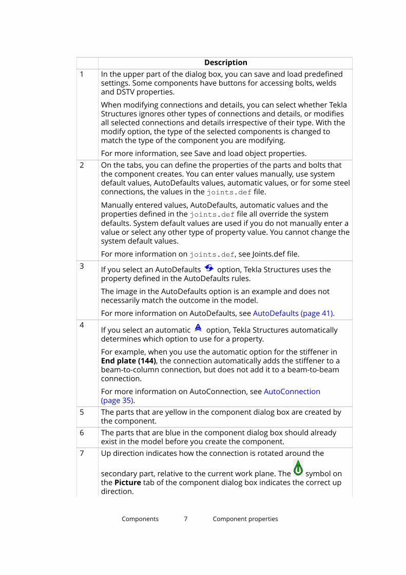
For more information on AutoDefaults, see AutoDefaults (page 41).4
If you select an automatic option, Tekla Structures automaticallydetermines which option to use for a property.
For example, when you use the automatic option for the stiffener inEnd plate (144), the connection automatically adds the stiffener to abeam-to-column connection, but does not add it to a beam-to-beamconnection.
For more information on AutoConnection, see AutoConnection(page 35).
5 The parts that are yellow in the component dialog box are created bythe component.
6 The parts that are blue in the component dialog box should alreadyexist in the model before you create the component.
7 Up direction indicates how the connection is rotated around the
secondary part, relative to the current work plane. The symbol onthe Picture tab of the component dialog box indicates the correct updirection.
Components 7 Component properties

DescriptionIf there are no secondary parts, Tekla Structures rotates the connectionaround the main part. The options are: +x, -x, +y, -y, +z, -z.
You can change the default up direction on the General tab of thecomponent dialog box. Try changing the positive directions first.
See also
Add a component to a model (page 8)
1.2 Add a component to a modelWhen you add a component to a model, you either attach the component toexisting parts in the model, or pick positions to indicate the location or lengthof the component.
Connections and details have a main part that you select first. Connectionsalso have one or more secondary parts that you select after you have selectedthe main part. Detailing components do not always have a main part andsecondary parts. Instead, they automatically create and assemble the parts tobuild a structure when you pick a position in the model.
If you use a component you are unfamiliar with, use the default properties ofthe component. Then check what needs to be modified, and modify only fewproperties at a time to see how the modifications affect the component. This isquicker than trying to set all the component properties before seeing what thecomponent actually creates.
Tekla Structures opens a command prompt when you add a component. Donot close the prompt window, because it displays information on adding thecomponent. This information can be useful in problem situations.
1. Click the Applications & components button in the side pane toopen the Applications & components catalog.
You can also press Ctrl + F.
2. Select a component and do one of the following:
To Do thisAdd aconnection
1. Select the main part.
2. Select the secondary part or parts.
• If there is one secondary part, the connection isautomatically created when you select the secondary part.
• If there are several secondary parts, click the middle mousebutton to finish selecting the parts and to create theconnection.
Components 8 Add a component to a model
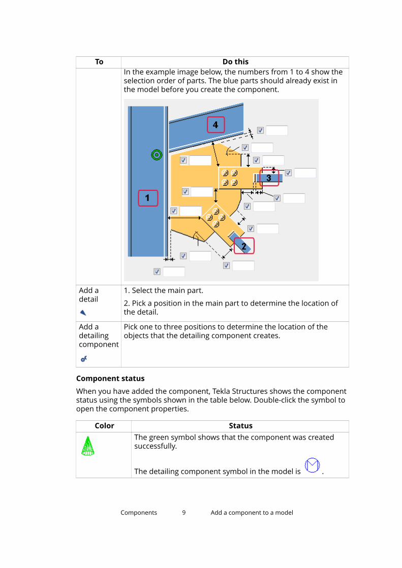
To Do thisIn the example image below, the numbers from 1 to 4 show theselection order of parts. The blue parts should already exist inthe model before you create the component.
Add adetail
1. Select the main part.
2. Pick a position in the main part to determine the location ofthe detail.
Add adetailingcomponent
Pick one to three positions to determine the location of theobjects that the detailing component creates.
Component status
When you have added the component, Tekla Structures shows the componentstatus using the symbols shown in the table below. Double-click the symbol toopen the component properties.
Color StatusThe green symbol shows that the component was createdsuccessfully.
The detailing component symbol in the model is .
Components 9 Add a component to a model
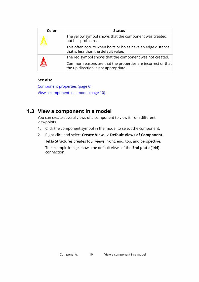
Color StatusThe yellow symbol shows that the component was created,but has problems.
This often occurs when bolts or holes have an edge distancethat is less than the default value.The red symbol shows that the component was not created.
Common reasons are that the properties are incorrect or thatthe up direction is not appropriate.
See also
Component properties (page 6)
View a component in a model (page 10)
1.3 View a component in a modelYou can create several views of a component to view it from differentviewpoints.
1. Click the component symbol in the model to select the component.
2. Right-click and select Create View --> Default Views of Component .
Tekla Structures creates four views: front, end, top, and perspective.
The example image shows the default views of the End plate (144)connection.
Components 10 View a component in a model
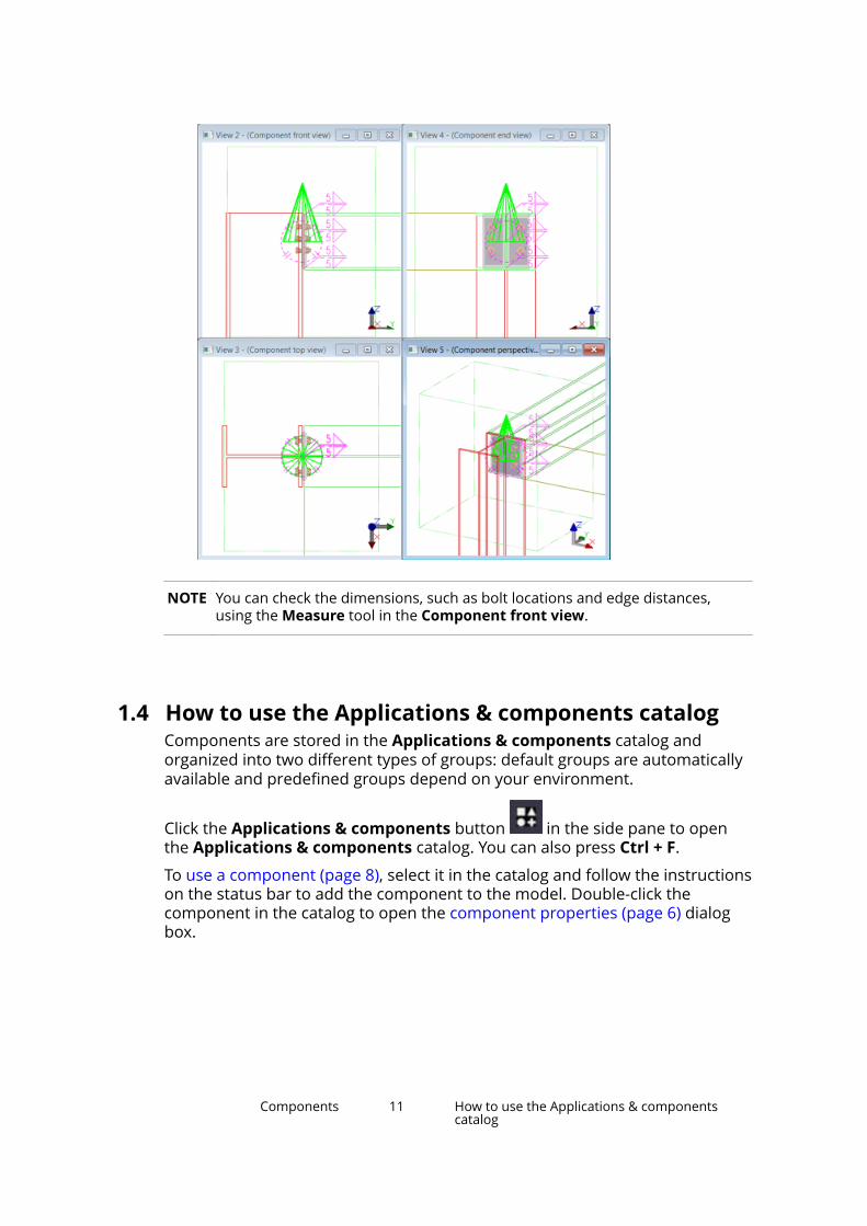
NOTE You can check the dimensions, such as bolt locations and edge distances,using the Measure tool in the Component front view.
1.4 How to use the Applications & components catalogComponents are stored in the Applications & components catalog andorganized into two different types of groups: default groups are automaticallyavailable and predefined groups depend on your environment.
Click the Applications & components button in the side pane to openthe Applications & components catalog. You can also press Ctrl + F.
To use a component (page 8), select it in the catalog and follow the instructionson the status bar to add the component to the model. Double-click thecomponent in the catalog to open the component properties (page 6) dialogbox.
Components 11 How to use the Applications & componentscatalog

Groups in the catalogDefault groups and predefined groups are shown against differentbackground color in the catalog.
Default groups are automatically available:
• Recent contains the 12 components and applications that have mostrecently been used in the model.
• Ungrouped items contains the components and applications that are notin any predefined group.
Ungrouped items can be, for example, imported components that have notbeen moved to any other group yet.
• Applications contains applications (page 25), macros and drawingplugins.
If you create your own macros, you can add them to this group.
• Connections contains connections and seams.
• Detailing contains detailing components.
• Details contains details.
• Parts contains custom parts.
• Legacy catalog shows the folder structure of the Component Catalogused in previous Tekla Structures versions if the catalog definition files arefound in the standard folder search paths.
Depending on your environment, the catalog may also contain predefinedgroups for specific usage, such as Steel > Beam to beam connections. Youcan create your own groups according to your needs, for example, for yourown favorite connections. This way you can find these connections fast andeasily. You can also hide the groups that you are not using so that only thegroups you use are visible in the catalog.
Model-specific components are shown in the modeling mode and drawing-specific components are shown in the drawing mode.
Search for a component in the catalogTo search for a component in the catalog, enter the search term in the searchbox. The search is case-insensitive.
Note that the search does not find catalog content that has been hidden.Select the Show hidden items check box to show the hidden content.
The search uses the following rules:
Components 12 How to use the Applications & componentscatalog
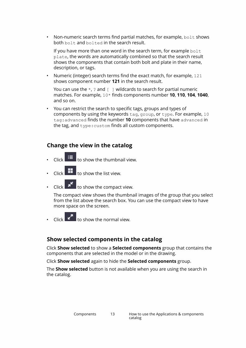
• Non-numeric search terms find partial matches, for example, bolt showsboth bolt and bolted in the search result.
If you have more than one word in the search term, for example boltplate, the words are automatically combined so that the search resultshows the components that contain both bolt and plate in their name,description, or tags.
• Numeric (integer) search terms find the exact match, for example, 121shows component number 121 in the search result.
You can use the *, ? and [ ] wildcards to search for partial numericmatches. For example, 10* finds components number 10, 110, 104, 1040,and so on.
• You can restrict the search to specific tags, groups and types ofcomponents by using the keywords tag, group, or type. For example, 10tag:advanced finds the number 10 components that have advanced inthe tag, and type:custom finds all custom components.
Change the view in the catalog
• Click to show the thumbnail view.
• Click to show the list view.
• Click to show the compact view.
The compact view shows the thumbnail images of the group that you selectfrom the list above the search box. You can use the compact view to havemore space on the screen.
• Click to show the normal view.
Show selected components in the catalogClick Show selected to show a Selected components group that contains thecomponents that are selected in the model or in the drawing.
Click Show selected again to hide the Selected components group.
The Show selected button is not available when you are using the search inthe catalog.
Components 13 How to use the Applications & componentscatalog

View and modify component information in the catalogEach component has an information box that shows the type of thecomponent and the groups the component belongs to. You can add adescription for the component and tags that can be used in the search.
1. Select a component and click the small arrow on the right to open thecomponent information box.
2. Type a description in the Description box.
3. Click to add a tag and enter a tag in the box.
4. If needed, click again to add more tags. You can also remove tags.
5. Click outside the information box to close it.
The descriptions and tags that you add are by default saved in theComponentCatalog.xml file in the model folder.
Add a thumbnail image for a component in the catalogComponents have a default thumbnail image that shows a typical situationwhere the component can be used. You can add several thumbnails for acomponent and select which thumbnail is shown in the thumbnail view in theApplications & components catalog.
1. Select a component in the catalog.
2. Right-click and select Thumbnails.
3. Click Add thumbnail.
4. Select an image and click Open. You can use any standard image format,for example, .png, .jpeg, .gif, .tiff, and .bmp.
5. Select the check boxes of the thumbnails that you want to show in thecomponent information box. You can also remove thumbnails, except forthe default thumbnail.
6. Click Close.
The thumbnail information that you add is by default saved in theComponentCatalog.xml file in the model folder.
Create and modify groups in the catalogYou can create groups and subgroups, and move groups to different locationsin the predefined groups section in the catalog. You can add and removecomponents from the groups, rename the groups, and add descriptions forthe groups.
Components 14 How to use the Applications & componentscatalog
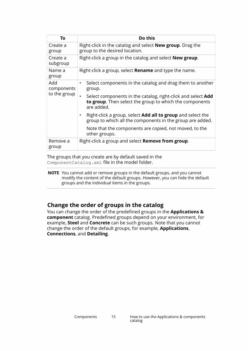
To Do thisCreate agroup
Right-click in the catalog and select New group. Drag thegroup to the desired location.
Create asubgroup
Right-click a group in the catalog and select New group.
Name agroup
Right-click a group, select Rename and type the name.
Addcomponentsto the group
• Select components in the catalog and drag them to anothergroup.
• Select components in the catalog, right-click and select Addto group. Then select the group to which the componentsare added.
• Right-click a group, select Add all to group and select thegroup to which all the components in the group are added.
Note that the components are copied, not moved, to theother groups.
Remove agroup
Right-click a group and select Remove from group.
The groups that you create are by default saved in theComponentCatalog.xml file in the model folder.
NOTE You cannot add or remove groups in the default groups, and you cannotmodify the content of the default groups. However, you can hide the defaultgroups and the individual items in the groups.
Change the order of groups in the catalogYou can change the order of the predefined groups in the Applications &component catalog. Predefined groups depend on your environment, forexample, Steel and Concrete can be such groups. Note that you cannotchange the order of the default groups, for example, Applications,Connections, and Detailing.
Components 15 How to use the Applications & componentscatalog

You can control the order with a sort index. The Sort index option is availablein the group information of each predefined group in the Applications &components catalog. Sort indexes are saved in the catalog definition files.
You can change the sort index by entering either a negative or a positiveinteger number, or 0, in the Sort index option box. A negative sort indexmoves a group towards the top and a positive sort index moves a grouptowards the bottom in the predefined groups section. Enter 0 or clear thevalue to revert to the default order. By default, the groups are in alphabeticalorder.
The sort index changes you make are model specific and they are saved in theComponentCatalog.xml file in the \model folder. Administrators can definethe order of groups for an environment or a project using the catalogdefinition files in the environment, firm and project folders. Do not edit thesefiles if you are not an administrator.
Note that even if administrators have defined the order, you can still makemodel-specific changes to the order of the groups by entering a different sortindex value for a group. If you need to revert to the default order, enter 0 asthe sort index.
To change the order:
1. Select a predefined group.
2. Click the small arrow on the right to open the group information box.
3. Enter a number in the Sort index box.
The group is immediately moved.
4. Save the model to keep the order.
Components 16 How to use the Applications & componentscatalog
Hide groups and components in the catalog1. Select a group or a component in the catalog.
2. Right-click and select Hide / Unhide to hide the group or the component.
3. To view the hidden group or component again, select the Show hiddenitems check box at the bottom of the catalog. The hidden group orcomponent is shown as dimmed.
4. To show the hidden group or component normally, right-click it and selectHide / Unhide.
Show the catalog message logIf there are errors or warnings, for example, in the catalog definition files, theDisplay message log button is shown in the lower right corner in the catalog.The button is not shown if there are no errors or warnings.
To view the error log, click the Display message log button.
Errors and warnings are also written to the ComponentCatalog_<user>.logfile in the \logs folder under the model folder.
Catalog definitions
The commands in Access advanced features > Catalog managementare used for modifying catalog definitions. Generally, there is no need tomodify catalog definitions. Do not modify the definition files if you are not anadministrator. For more information on administrator tasks, see Applications& components catalog for administrators.
1.5 Steel component example: Add an end plate using theEnd plate (144) connectionIn this example, you will connect a beam to a column using an end plateconnection. End plate (144) connects two beams, or a beam to a column,using a bolted end plate.
1. Click the Applications & components button in the side pane toopen the Applications & components catalog.
2. Type 144 in the search box.
3. Double-click End plate (144) to open the component properties.
4. Click Apply to add the component using the default properties.
Components 17 Steel component example: Add an end plateusing the End plate (144) connection

5. Select the main part (column).
6. Select the secondary part (beam).
Tekla Structures automatically adds the connection when you select thebeam.
See also
Add a component to a model (page 8)
1.6 Steel component example: Add a base plate andanchor rods using the Base plate (1004) detailIn this example, you will add a base plate detail and anchor rods to a column.
1. Click the Applications & components button in the side pane toopen the Applications & components catalog.
2. Enter base plate in the search box.
To view the thumbnail images of the components in the search results
click .
3. Select Base plate (1004).
4. Select the column.
5. Pick a position at the base of the column.
Tekla Structures automatically adds the base plate when you pick theposition.
6. Next, modify the anchor rod dimensions.
a. Switch on the Select components switch to more easily selectcomponents.
Components 18 Steel component example: Add a base plate andanchor rods using the Base plate (1004) detail

b. Double-click the component symbol in the model to open the Baseplate (1004) component dialog box.
c. Go to the Anchor rods tab.
d. Change the dimensions of the anchor rods.
e. To change only this base plate, select ignore other types from the listin the top part of the dialog box.
f. Click Modify.
See also
Add a component to a model (page 8)
1.7 Steel component example: Add a beam-to-columnconnection using the Column with stiffeners (186)connectionIn this example, you will connect a beam to a column using a beam-to-columnconnection.
1. Click the Applications & components button in the side pane toopen the Applications & components catalog.
2. Enter 186 in the search box.
3. Select Column with stiffeners (186).
4. Select the main part (column).
5. Select the secondary part (beam).
Components 19 Steel component example: Add a beam-to-column connection using the Column withstiffeners (186) connection

Tekla Structures automatically adds the connection when you select thebeam.
See also
Add a component to a model (page 8)
1.8 Concrete component example: Add a corbelconnection using the Corbel connection (14)connectionIn this example, you will add a corbel connection between a column and abeam.
1. Click the Applications & components button in the side pane toopen the Applications & components catalog.
2. Enter corbel in the search box.
3. Select Corbel connection (14).
4. Select the main part (column).
5. Select the secondary part (beam).
Components 20 Concrete component example: Add a corbelconnection using the Corbel connection (14)connection
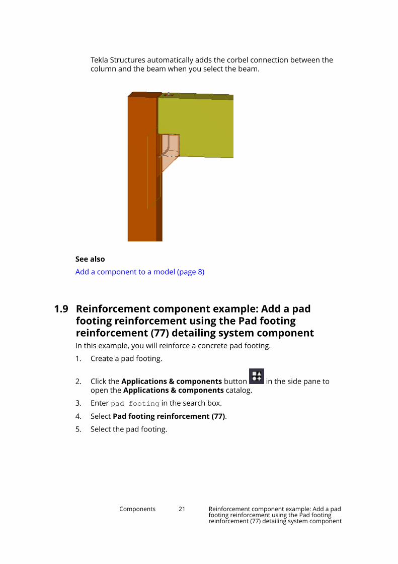
Tekla Structures automatically adds the corbel connection between thecolumn and the beam when you select the beam.
See also
Add a component to a model (page 8)
1.9 Reinforcement component example: Add a padfooting reinforcement using the Pad footingreinforcement (77) detailing system componentIn this example, you will reinforce a concrete pad footing.
1. Create a pad footing.
2. Click the Applications & components button in the side pane toopen the Applications & components catalog.
3. Enter pad footing in the search box.
4. Select Pad footing reinforcement (77).
5. Select the pad footing.
Components 21 Reinforcement component example: Add a padfooting reinforcement using the Pad footingreinforcement (77) detailing system component
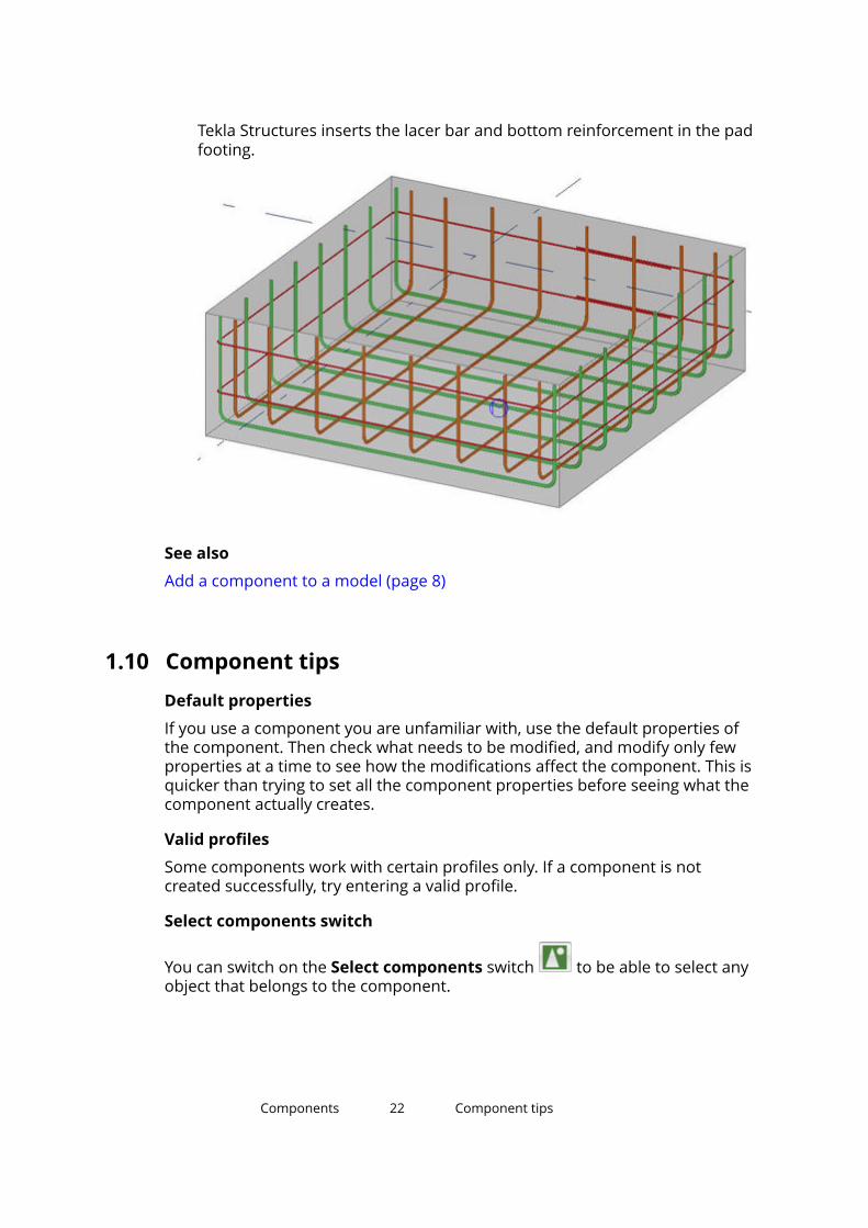
Tekla Structures inserts the lacer bar and bottom reinforcement in the padfooting.
See also
Add a component to a model (page 8)
1.10 Component tipsDefault properties
If you use a component you are unfamiliar with, use the default properties ofthe component. Then check what needs to be modified, and modify only fewproperties at a time to see how the modifications affect the component. This isquicker than trying to set all the component properties before seeing what thecomponent actually creates.
Valid profiles
Some components work with certain profiles only. If a component is notcreated successfully, try entering a valid profile.
Select components switch
You can switch on the Select components switch to be able to select anyobject that belongs to the component.
Components 22 Component tips

Component is not added to the model
If the component is not added to the model, check the status bar. Forexample, you may need to click the middle mouse button to stop selectingparts before Tekla Structures creates the component.
Using thickness to create needed parts
If a component does not by default create the parts that you need, look foroptions to create them. If there are no options, try entering a thickness valuefor the parts.
If a component creates parts that you do not need, look for options to removethem. If there are no options, enter a zero (0) as the thickness of the parts.
Many secondary parts are found
If you are using a connection that only allows one secondary part, you may seethe message Many parts found on the status bar. This means that TeklaStructures cannot determine which parts to connect. You may have severalparts in the same location, or the view may be set too deep.
1.11 Converting a conceptual or a detailed componentDepending on the Tekla Structures configuration you are using, you can createeither detailed or conceptual components.
• Detailed components include all the information needed for fabrication,such as assemblies, cast units, and reinforcing bars.
Detailed components have a round symbol in the model: or .
• Conceptual components look similar to detailed components but do notinclude the option to change part numbering or assembly numberingsettings. Conceptual components are meant to be used as referenceinformation for further fabrication detailing.
Conceptual components have a rectangular symbol in the model: or
.
You can create conceptual components in the Engineering, Rebar Detailing,and Construction Modeling configurations.
Components 23 Converting a conceptual or a detailed component

You can edit conceptual components and convert them to detailedcomponents in the Full, Primary, Steel Detailing, or Precast ConcreteDetailing configurations.
Modifying part properties, such as the size of the component main part, doesnot automatically convert a detailed component to a conceptual component,or vice versa. For example, if you use the Engineering configuration andmodify the model, detailed components are not converted to conceptualcomponents. However, when you modify a detailed component in the RebarDetailing configuration, the component changes to a conceptual component.
You can convert components in the Applications & components catalog. Click
the Applications & components button in the side pane to open theApplications & components catalog.
Do one of the following:
To Do this ConfigurationConvert aconceptualcomponentto a detailedcomponent
1.Click > Convert todetailing component.
2. Select the componentsymbol.
Full, Primary, SteelDetailing, Precast ConcreteDetailing
Convert adetailedcomponentto aconceptualcomponent
1.Click >Convert toconceptual component.
2. Select the componentsymbol.
Engineering, ConstructionModeling, Rebar Detailing
Components 24 Converting a conceptual or a detailed component

2 Applications
All available applications, macros, and drawing plugins are located in thesection Applications of the Applications & components catalog. You can alsorecord macros of your own and show them on the list.
Macros
Macro types of applications (page 27) are saved as .cs files in the\drawings or \modeling folder under the folder that has been defined withthe advanced option XS_MACRO_DIRECTORY. By default, this advanced optionis set to ..\ProgramData\Tekla Structures\<version>\environments\common\macros.
In addition to this global folder, you can create a local folder and save yourown macros there. To use the local macros, you need to specify the localmacro folder for the advanced option XS_MACRO_DIRECTORY in addition tothe global folder.
Available macros in the modeling mode
Macro DescriptionAutoConnectSelectedParts (page 39) Use to automatically create
connections without opening theAutoConnection dialog box.
AutomaticSplicingTool Use to split long reinforcing bars andbar groups that exceed the stocklength, and create splices in splitlocations.
ContinuousBeamReinforcement Use to reinforce a continuous beam.The macro creates main top andbottom bars, stirrups, fittings, andadditional top and bottom bars usingsystem components.
Convert_DSTV2DXF Use to create NC files in DXF formatby converting DSTV files to DXF files.
Applications 25 Converting a conceptual or a detailed component

Macro DescriptionCreateSurfaceView Use to create an automatically aligned
surface view.CreateSurfaceView_wEdge Use to create a surface view and align
the work plane along the edge youselect.
DesignGroupNumbering Use to number parts by designgroups so that you can differentiatethe parts from each other in drawingsand reports.
DirectoryBrowser Use to to find and modify the locationof the various Tekla Structures filesand folders, and customize usersettings.
RebarClassificator Use to classify the reinforcing barsand reinforcement meshes by theirorder of depth in concrete slabs andpanels.
RebarSeqNumbering Use to assign cast unit specificrunning numbers (1, 2, 3...) to thereinforcement in the model.
RebarSplitAndCoupler Use to split a reinforcing bar groupand add couplers in relation to thedirection of the picked points.
UpdateRebarAttributes Use to manage the user-definedattributes (UDAs) of the couplers andthe end anchor parts created byRebar Coupler and Anchor Tools.
Available macros in the drawing mode
Macro DescriptionAddSurfaceSymbols Use to add surface treatment symbols
in cast unit drawings.Copy with offfsets (Drawing tools) Use to copy lines, circles, polylines,
polygons and rectangles with offsets.Create fillets (Drawing tools) Use to connect two intersecting lines
by extending the two selected lines totheir intersection point.
Create chamfers (Drawing tools) Use to create chamfers between twolines using the distance that youspecify.
Manage cut lines (Drawing tools) Use to create lines that are displayedwith a zigzag or a dash-and-dot in
Applications 26 Converting a conceptual or a detailed component

Macro Descriptiondifferent colors to show that the lineis partially outside the view border.
Create moment connection symbols(Drawing tools)
Use to create moment connectionsymbols to show the beams that areconnected to columns with rigidconnections.
ExaggerateSelectedDimensions Use to exaggerate narrow dimensionsto make them easier to read.
RebarLayeringMarker Use to mark reinforcing bar layerswith different marking styles and linetypes in a drawing.
RebarMeshViewCreator Use to create drawing views eachcontaining one reinforcement mesh.
RemoveChangeClouds Use to remove dimension changesymbols, mark change symbols andassociative note change symbols inone go from an open drawing.
Extensions (.tsep)
You can download Tekla Structures extensions that have the .tsep fileextension from Tekla Warehouse and import (page 31) these extensions tothe Applications & components catalog. When you restart Tekla Structures,the imported extensions are installed and added to the Ungrouped itemsgroup in the catalog. You can move them to a suitable group.
Publish groups in the Applications & components catalog
You can collect content to a group that you create in the Applications &components catalog. You can then publish the group (page 32) as a catalogdefinition file to make it available for other Tekla Structures users.
2.1 Working with applicationsYou can run, add, edit, rename, save as and delete applications, macros andplugins in the Applications section of Applications and Components catalog.You can also record and edit macros.
To Do thisRecord a macro 1. Click the Applications &
components button in theside pane to open theApplications & componentscatalog.
Applications 27 Working with applications
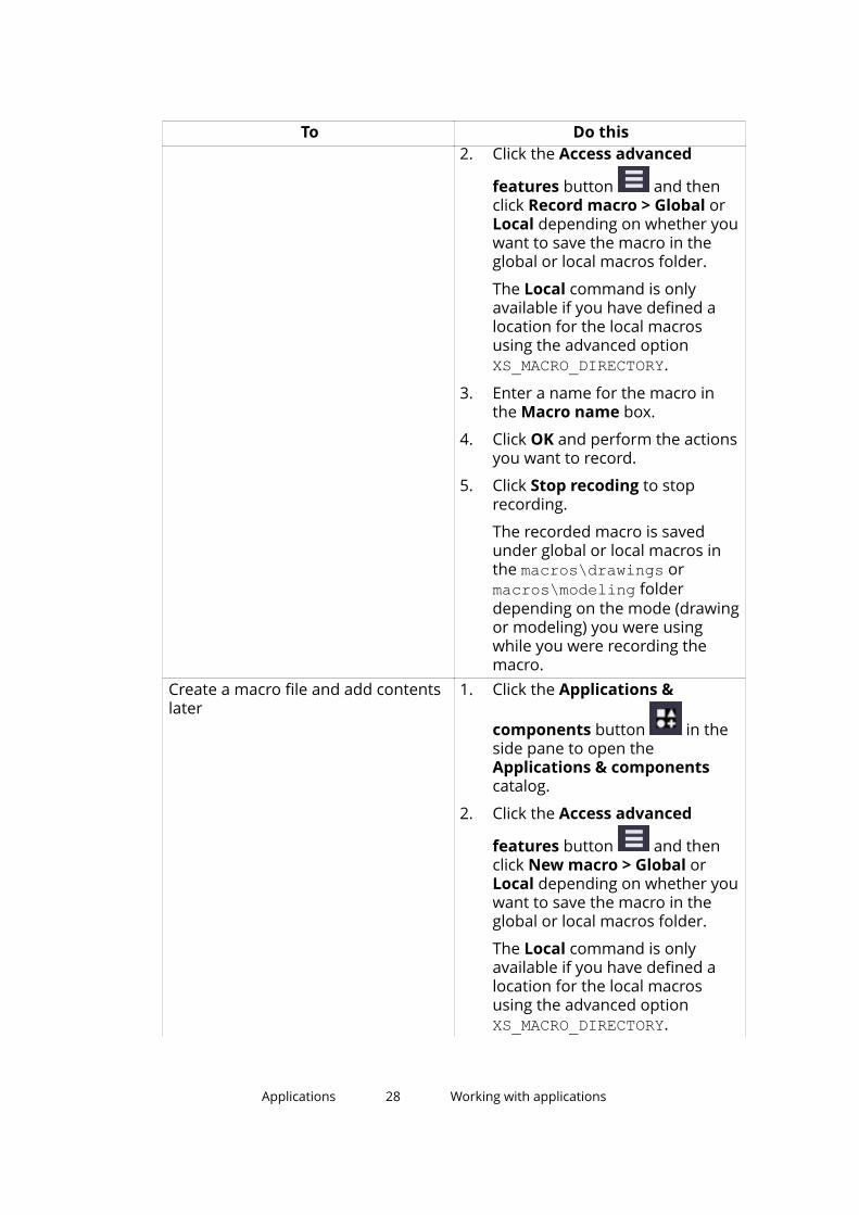
To Do this2. Click the Access advanced
features button and thenclick Record macro > Global orLocal depending on whether youwant to save the macro in theglobal or local macros folder.
The Local command is onlyavailable if you have defined alocation for the local macrosusing the advanced option XS_MACRO_DIRECTORY.
3. Enter a name for the macro inthe Macro name box.
4. Click OK and perform the actionsyou want to record.
5. Click Stop recoding to stoprecording.
The recorded macro is savedunder global or local macros inthe macros\drawings ormacros\modeling folderdepending on the mode (drawingor modeling) you were usingwhile you were recording themacro.
Create a macro file and add contentslater
1. Click the Applications &
components button in theside pane to open theApplications & componentscatalog.
2. Click the Access advanced
features button and thenclick New macro > Global orLocal depending on whether youwant to save the macro in theglobal or local macros folder.
The Local command is onlyavailable if you have defined alocation for the local macrosusing the advanced option XS_MACRO_DIRECTORY.
Applications 28 Working with applications

To Do this3. Enter a name for the macro in
the Macro name box.
4. Click OK.
This creates an empty macro filethat is displayed in theApplications list.
5. Right-click the empty macro fileand select Edit.
6. Add the macro content, forexample, by copying commandsfrom other macro files and savethe file.
View or edit a macro 1. Click the Applications &
components button in theside pane to open theApplications & componentscatalog.
2. Click the arrow next toApplications to open theapplications list.
3. Right-click the macro you want toedit and click Edit.
The macro can be opened in anytext editor.
4. If needed, edit the macro andsave the macro file.
Run an application 1. Click the Applications &
components button in theside pane to open theApplications & componentscatalog.
2. Click the arrow next toApplications to open theapplications list.
3. Double-click the application youwant to run.
Save an application with anothername
1. Click the Applications &
components button in theside pane to open the
Applications 29 Working with applications

To Do thisApplications & componentscatalog.
2. Click the arrow next toApplications to open theapplications list.
3. Right-click the application thatyou want to save with anothername and click Save as.
4. Enter a new name for theapplication and click OK.
The application will be added inthe list.
Rename an application 1. Click the Applications &
components button in theside pane to open theApplications & componentscatalog.
2. Click the arrow next toApplications to open theapplications list.
3. Right-click the application youwant to rename and clickRename.
4. Enter a new name for theapplication and click OK.
The name of the applicationchanges.
Delete an application 1. Click the Applications &
components button in theside pane to open theApplications & componentscatalog.
2. Click the arrow next toApplications to open theapplications list.
3. Right-click the application youwant to delete and click Delete.
The application is removed fromthe list.
Applications 30 Working with applications

See also
Applications (page 25)
2.2 Import a .tsep extension to the Applications &components catalogYou can import Tekla Structures .tsep extensions (Tekla Structures extensionpackage) to the Applications & components catalog. First download theextension from Tekla Warehouse, and then import it to the catalog.
NOTE Some Tekla Structures extensions have an .msi installation file. Youhave to install these extensions separately. Download the .msiinstallation file from Tekla Warehouse and double-click the file to runthe installation.
1. Click the Applications & components button in the side pane toopen the Applications & components catalog.
2. Click > Manage extensions > Extension manager.
Alternatively, you can open Extension manager from File menu -->Extend --> Extension manager.
3. Click the Tekla Warehouse link and log in to Tekla Warehouse with yourTrimble Identity.
4. Search for the .tsep extension and click Download.
5. Click the downloaded extension in your browser.
Tekla Structures opens a dialog box that lists the installed Tekla Structuresversions that are compatible with the extension.
6. Select the Tekla Structures versions to which you want to import theextension.
7. Click Import.
The extension is shown in Extension manager in all the Tekla Structuresversions that you selected.
Alternatively, if you want to import the extension to the current TeklaStructures version only, you can do the import in Extension managerafter downloading the extension. In Extension manager, click Importand then double-click the .tsep file.
You can still remove the extension from Extension manager beforeinstalling it. Select the extension and click Cancel.
8. If needed, repeat steps 4 - 7 to import more Tekla Structures extensions.
Applications 31 Import a .tsep extension to the Applications &components catalog

9. Restart Tekla Structures to install the imported extension.
10. Open the Applications & components catalog.
The extension is shown in the Ungrouped items group in the catalog. Youcan move the extension to a more suitable group, or create a new group.
You can uninstall an installed extension in Extension manager. Select theextension and click Remove. The extension is removed when you restart TeklaStructures. Installing and uninstalling an extension creates a log file to \TeklaStructures\<version>\Extensions\TSEP Logs.
System administrators can copy multiple .tsep extension files to a TeklaStructures user's computer to the \Tekla Structures\<version>\Extensions\To be installed folder. The extensions are installed thenext time the user restarts Tekla Structures.
Copy .tsep extensions to a new Tekla Structures version
When starting to use a new Tekla Structures version, you can use the MigrationWizard tool to copy the installed .tsep extensions to the new version. You canopen Migration Wizard either from the Applications & components catalog,
click > Manage extensions > Migrate extensions, or from File menu -->Extend --> Migrate extensions. Once copied, the extensions are listed inExtension manager in the new Tekla Structures version. Restart TeklaStructures to install the copied extensions.
See also
How to use the Applications & components catalog (page 11)
2.3 Publish a group in the Applications & componentscatalogYou can collect content, such as macros, extensions, and system and customcomponents to a group that you create in the Applications & componentscatalog. You can then publish the group as a catalog definition file to make itavailable for other Tekla Structures users. For the published content to workcorrectly in another Tekla Structures installation, the content must also exist inthat installation.
1. Click the Applications & components button in the side pane toopen the Applications & components catalog.
2. Create a new group:
a. Right-click in the catalog and select New group.
b. Enter a name for the group.
Applications 32 Publish a group in the Applications & componentscatalog

c. Select the group and click the small arrow on the right to add adescription to the group.
d. Add content (page 11) to the group.
Some content in the Applications & components catalog may behidden. To publish the hidden content, select the Show hidden itemscheck box at the bottom of the catalog.
Note that the model-specific items you add to the group are visible inthe modeling mode and the drawing-specific items in the drawingmode.
e. Add the needed information to the items (page 11) in the group:description, tags, and additional thumbnail images.
Use a thumbnail image from the \Tekla Structures\<version>\Bitmaps folder to ensure that the image is available for other TeklaStructures users.
3. Right-click the group and select Publish group to create a catalogdefinition file.
The file contains the following information:
• Name and description of the published group
• Names and descriptions of the subgroups
• References to the items that you have added to the group
The file does not contain the actual items. When other users use thegroup, they must ensure that the referenced items exist in their TeklaStructures installation and model.
• Descriptions, tags and thumbnail references of the items in the group
The file does not contain the actual thumbnail image files.
4. Add a unique prefix to the filename in the Publish group dialog box.
The filename format must be <prefix>_ComponentCatalog.ac.xml.
5. Click Save.
The file is by default saved to the model folder.
6. Make the group available for other Tekla Structures users by placing the<prefix>_ComponentCatalog.ac.xml catalog definition file to anappropriate folder:
• Project, firm or system folder defined in XS_PROJECT, XS_FIRM, or XS_SYSTEM.
• \attributes folder under the current model folder
Applications 33 Publish a group in the Applications & componentscatalog
• Extensions folder in \Tekla Structures\<version>\environments\common\extensions, or to any of the foldersdefined in XS_EXTENSION_DIRECTORY.
The Applications & components catalog also searches the subfoldersof these folders. We recommend that you use the extension folders ifyou have created your own extensions and have included them in thegroup.
7. Check that the catalog definition file works correctly:
a. Delete the published group from your Applications & componentscatalog.
b. Click > Catalog managementReload catalog to load and viewthe published group.
When you have checked the group, other users can start using it:
• If the group content is already included in other users' Tekla Structuresinstallation, they can use the group immediately after reloading the catalog
by clicking > Catalog management > Reload catalog.
• If the group content, for example extensions, is not included in other users'Tekla Structures installation, they have to download the missing extensionsfrom Tekla Warehouse first, and then re-open the model where they aregoing to use the group.
Applications 34 Publish a group in the Applications & componentscatalog
3 AutoConnection
Use the AutoConnection tool to automatically select and apply connectionswith predefined properties to selected parts in a model. With AutoConnection,Tekla Structures automatically creates similar connections for similar framingconditions.
You can use AutoConnection to quickly add connections individually, inphases, or project-wide. This is useful when you are working on a large projectusing many connections, modifying a model, or importing modified profiles.
NOTE Before using AutoConnection in a working model, we recommend that youcreate a test model, and create all the connection conditions in it that youneed for a particular project. You can then use the test model to check therules and properties of various connection types. The model also acts as aquick reference for connection information.
See also
AutoConnection settings (page 35)
Create a connection using AutoConnection (page 39)
AutoConnection and AutoDefaults rules (page 48)
3.1 AutoConnection settingsWith AutoConnection you can define groups of rules which Tekla Structuresautomatically applies when creating connections in a model. By using a rulegroup to select connections and connection properties you do not have toselect each connection and define its properties separately. For example, youcan create separate rules for different standards, projects, manufacturers, andeven individual models.
AutoConnection 35 AutoConnection settings

To open the AutoConnection Setup dialog box, click File menu --> Catalogs --> AutoConnection settings.
Icon Setup level DescriptionRule group You can use rule groups to organize
connections and connection propertiesaccording to different standards,projects, manufacturers, and models.You can create, modify and delete rulegroups.
Framing condition Framing conditions are predefinedconnection types that you cannotchange. Tekla Structures creates theframing conditions automatically:
• Beam to beam web
• Beam to beam flange
• Beam to column web
• Beam to column flange
• Beam splice
• Column splice
AutoConnection 36 AutoConnection settings

Icon Setup level DescriptionRule set You can use rule sets to define which
connection to use in a certain situation.You can create additional rule sets.
Connection The connection to apply if the rule setcriteria are met.
To apply a particular connection, theconditions in the model have to matchall the rules in the branch that containsthe connection.
Rules.zxt file
When you use AutoConnection, Tekla Structures saves the AutoConnectioninformation in a zipped rules.zxt file in the \attributes folder under thecurrent model folder.
You can copy the rules.zxt file to the project or firm folder to make itavailable in other models. Each time you modify the AutoConnection setupyou need to recopy this file to the firm and project folders. To use the modifiedsetup in other models, restart Tekla Structures.
See also
Create a rule group for AutoConnection (page 37)
Create a rule set for AutoConnection (page 38)
Change a connection in an AutoConnection rule set (page 38)
Create a rule group for AutoConnectionYou can define rule groups for AutoConnection to organize connections andconnection properties according to different standards, projects,manufacturers, and models.
1. On the File menu, click Catalogs --> AutoConnection settings.
2. Right-click an existing rule group and select New Rule Group.
3. Click the New group and enter a name.
Give the rule group a name that reflects the group of connections that youwant to create. For example, use the fabricator's name, the project name,or any name that clearly identifies the connection rules that you want touse for a specific model.
When you create a new rule group, Tekla Structures automatically adds theexisting framing conditions in the group.
AutoConnection 37 AutoConnection settings

See also
Create a rule set for AutoConnection (page 38)
Create a connection using AutoConnection (page 39)
Create a rule set for AutoConnectionYou can create AutoConnection rule sets under framing conditions to specifywhich connection properties to use when specific conditions in the model aremet.
You only need to create AutoConnection rule sets if you plan to use differentconnections to connect similar framing conditions. For example, in the model,some beam-to-beam connections require clip angles, others need shear tabs.You need to define rule sets to determine where each connection type shouldbe used.
1. On the File menu, click Catalogs --> AutoConnection settings.
2. Click the plus icon in front of the rule group to open the tree structure.
3. Right-click the relevant framing condition and select CreateAdditional Rule Sets.
4. Right-click the new rule set and select Edit Rule Set.
5. Enter a name for the rule set.
6. Select a rule from the Available rules list.
7. Click the right arrow button to move the selected rule into the list of Rulesin the rule set.
8. Enter the values used in the rule: either an exact value, or minimum andmaximum values.
9. Click OK.
NOTE The order of the rules in the tree structure is important. Tekla Structures usesthe first rule that matches the conditions in the model so you should place themost limiting rule highest in the tree, and the most generic rule lowest.
You can change the priority of a rule set by right-clicking the rule set andselecting Move Up or Move Down.
See also
Change a connection in an AutoConnection rule set (page 38)
Create a connection using AutoConnection (page 39)
AutoConnection 38 AutoConnection settings
Change a connection in an AutoConnection rule setYou can change the connection in a rule set by selecting a connection in theApplications & components catalog.
1. On the File menu, click Catalogs --> AutoConnection settings.
2. Click the plus icon in front of the relevant framing condition and rule
set to find the connection that you want to change.
3. Right-click the connection and select Select Connection Type.
4. Double-click a connection in the Select component dialog box.
5. Click OK in the AutoConnection Setup dialog box.
See also
Create a connection using AutoConnection (page 39)
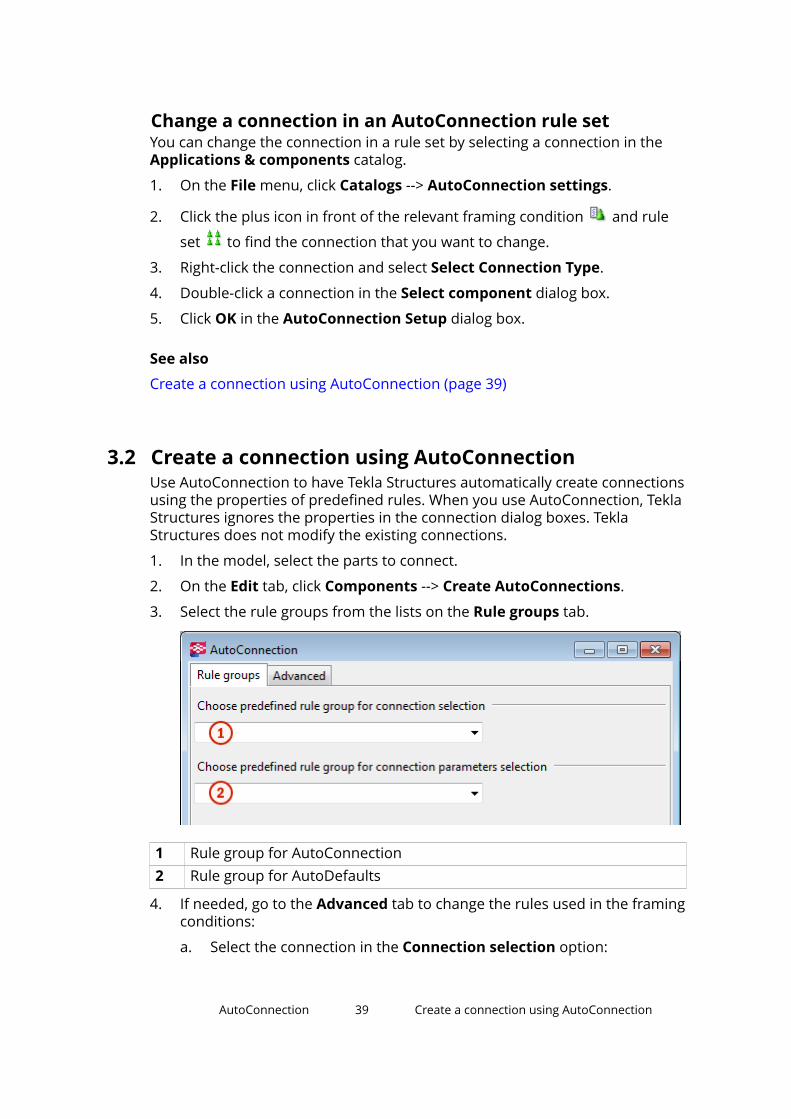
3.2 Create a connection using AutoConnectionUse AutoConnection to have Tekla Structures automatically create connectionsusing the properties of predefined rules. When you use AutoConnection, TeklaStructures ignores the properties in the connection dialog boxes. TeklaStructures does not modify the existing connections.
1. In the model, select the parts to connect.
2. On the Edit tab, click Components --> Create AutoConnections.
3. Select the rule groups from the lists on the Rule groups tab.
1 Rule group for AutoConnection2 Rule group for AutoDefaults
4. If needed, go to the Advanced tab to change the rules used in the framingconditions:
a. Select the connection in the Connection selection option:
AutoConnection 39 Create a connection using AutoConnection

• AutoConnection applies the connection defined in the rule groupthat you have selected in the first list on the Rule groups tab.
• None does not create a connection.
• Click Select to select a connection from the Applications &components catalog. Tekla Structures creates the connectionusing the default properties.
b. Select the connection properties in the Parameters selection option:
• AutoDefaults applies the properties of the rule group that youhave selected in the first list on the Rule groups tab.
• No autodefaults applies the default connection properties.
5. Click Create connections.
TIP You can also use the Auto connect selected parts macro to automaticallycreate connections using the current properties without opening theAutoConnection dialog box.
Macros are located in the Applications group in the Applications &components catalog.
See also
AutoConnection settings (page 35)
AutoConnection 40 Create a connection using AutoConnection
4 AutoDefaults
Use AutoDefaults to set up properties for existing connections. AutoDefaultsallows you to modify the default connection properties and save them for usein specific circumstances. When you use AutoDefaults, Tekla Structuresautomatically creates the connections with the predefined AutoDefaultsproperties. You can also use AutoDefaults for a single connection.
For example, you can use AutoDefaults to automatically adjust the thickness ofeach base plate you create, according to the main part profile. If the main partprofile changes, Tekla Structures automatically adjusts the thickness of thebase plate.
NOTE Before using AutoDefaults in a working model, we recommend that youcreate a test model, and create all the connection conditions in it that youneed for a particular project. You can then use this test model to check therules and properties of various connection types. It also acts as a quickreference for connection information.
See also
AutoDefaults settings (page 41)
Modify a connection using AutoDefaults (page 46)
AutoConnection and AutoDefaults rules (page 48)
4.1 AutoDefaults settingsUse AutoDefaults to set up properties for existing connections. WithAutoDefaults you can create rules that define the situations where thepredefined properties are used.
AutoDefaults 41 AutoDefaults settings

To open the AutoDefaults Setup dialog box, click File menu --> Catalogs -->AutoDefaults settings.
Icon Setup level DescriptionRule group You can use rule groups to organize settings
according to different standards, projects,manufacturers, and models. You can create,modify and delete rule groups.
Components The component tree structure shows theconnections that are available on componenttoolbars in Tekla Structures.
Rule set Rule sets control which properties to use incertain situations. You can create additional rulesets.
Tekla Structures processes AutoDefaults rule setsin the order in which they are in the tree, so youcan control the selection of properties.
Properties file The properties files are under the rule sets. Bydefault, each connection has a standardproperties file that defines the standard
AutoDefaults 42 AutoDefaults settings

Icon Setup level Descriptionproperties, for example, standard.j144 orstandard.j1042.
You can create additional properties files for theproperties that you want to use again and givethe files distinctive names.
Defaults.zxt file
When you use AutoDefaults, Tekla Structures saves the AutoDefaults rules in azipped defaults.zxt text file in the \attributes folder under the currentmodel folder.
You can copy the defaults.zxt file to the project or firm folder to make itavailable in other models. Each time you modify the AutoDefaults setup, youneed to recopy this file to the firm or project folder. To use the modified setupin other models, restart Tekla Structures.
NOTE We do not recommend that you edit the defaults.zxt file using atext editor, but if you do, ensure that you are using the right syntax.The easiest way to unzip the .zxt file is to change the fileextension .zxt to txt.gz and unzip the file. Change the extensionback to .zxt when you have finished. You do not need to zip the fileafter editing it, Tekla Structures can also read the unzipped file.
See also
Create a rule group for AutoDefaults (page 43)
Create a rule set for AutoDefaults (page 44)
Modify connection properties for AutoDefaults (page 45)
Create a rule group for AutoDefaultsYou can define rule groups for AutoDefaults to group the rules according todifferent standards, projects, or manufacturers, for example.
1. On the File menu, click Catalogs --> AutoDefaults settings.
2. Right-click an existing rule group and select New Rule Group.
3. Click the New group to rename it.
Give the rule group a name that reflects the contents of the group. Forexample, use the fabricator's name, the project name, or any name thatclearly identifies the rules that you want to use for a specific model.
When you create a new rule group, Tekla Structures automatically adds theexisting components to the group.
AutoDefaults 43 AutoDefaults settings
See also
Create a rule set for AutoDefaults (page 44)
Modify a connection using AutoDefaults (page 46)
Create a rule set for AutoDefaultsYou can create rule sets to define which connection properties are used whenspecific conditions in the model are met.
1. On the File menu, click Catalogs --> AutoDefaults settings.
2. Click the plus icon in front of the rule group to open the tree structure.
3. Click the plus icon in front of the relevant group of components andconnection .
4. Right-click an existing rule set and select New Rule Set.
5. Right-click the new rule set and select Edit Rule Set.
6. Enter a name for the rule set.
7. Select a rule from the Available rules list.
8. Click the right arrow button to move the selected rule into the list of Rulesin the rule set.
9. Enter the values used in the rule: either an exact value, or minimum andmaximum values.
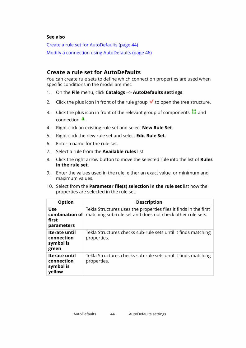
10. Select from the Parameter file(s) selection in the rule set list how theproperties are selected in the rule set.
Option DescriptionUsecombination offirstparameters
Tekla Structures uses the properties files it finds in the firstmatching sub-rule set and does not check other rule sets.
Iterate untilconnectionsymbol isgreen
Tekla Structures checks sub-rule sets until it finds matchingproperties.
Iterate untilconnectionsymbol isyellow
Tekla Structures checks sub-rule sets until it finds matchingproperties.
AutoDefaults 44 AutoDefaults settings

Option DescriptionUsecombination ofall parameters
Tekla Structures checks all rule sets and uses the propertiesfiles in all matching rule sets. The order of the propertiesfiles is important.
When Tekla Structures combines the properties files, themost recent files (the lowest in the tree) override previousones. If you do not enter any values for the properties,Tekla Structures does not override the previous propertyvalues.
11. Click OK.
NOTE The order of the rules in the tree structure is important. Tekla Structures usesthe first rule that matches the conditions within the model so you shouldplace the most limiting rule highest in the tree, and the most generic rulelowest.
You can change the priority of a rule set by right-clicking the rule set andselecting Move Up or Move Down.
See also
AutoDefaults settings (page 41)
Modify connection properties for AutoDefaults (page 45)
Combining and iterating properties for AutoDefaults (page 50)
Modify connection properties for AutoDefaultsEach connection has a default standard property file that defines theproperties for the connection. You can modify the properties that the standardfile uses. Save the connection properties that you want to use and set thestandard file to use these properties in the AutoDefaults settings.
1. On the File menu, click Catalogs --> AutoDefaults settings.
2. Click the plus icon in front of the rule group to open the tree structure.
3. Click the plus icon in front of the relevant group of components andconnection .
4. Right-click the standard.j connection file that you want to modify, forexample, standard.j144 and select Edit connection parameters.
5. In the connection dialog box, set the properties that you want to save.
Such properties could be, for example, bolt properties, profiles, andmaterials.
AutoDefaults 45 AutoDefaults settings

6. Enter a descriptive name for the properties in the box next to the Save asbutton.
7. Copy this name in the Connection code option on the General tab.
Using the same name allows you to check which properties TeklaStructures used in specific situations. Tekla Structures does notautomatically show the AutoDefaults values in the connection dialog box.
8. Click Save as.
Tekla Structures saves the properties file in the \attributes folderunder the current model folder. The filename consists of the name youentered in Save as and the file extension .jXXX, where XXX is theconnection number, for example, sec_0-190.j144.
9. Click Cancel to close the connection dialog box and return to theAutoDefaults Setup dialog box.
If you click OK to close the connection dialog box, you need to load thedefault properties the next time you use the connection. Using the defaultproperties ensures that AutoDefaults can modify the properties.
10. Right-click the standard.j file again and select Select connectionparameters.
The Attribute File List dialog box that opens contains the properties thathave been set and saved in the connection dialog box.
11. Select a file in the Attribute File List dialog box.
12. Click OK.
See also
Modify a connection using AutoDefaults (page 46)
4.2 Modify a connection using AutoDefaultsWhen you use a connection that you are unfamiliar with, first use the defaultproperties. Then use AutoDefaults to modify the properties.
1. Double-click a connection symbol in the model to open the connectiondialog box.
2. On the General tab, select a rule group from the AutoDefaults rulegroup list.
3. On all tabs, select the AutoDefaults options marked with the arrow symbol for the properties in which you want to use AutoDefaults.
4. Click Apply.
AutoDefaults 46 Modify a connection using AutoDefaults

If you manually modify the properties after using AutoDefaults, TeklaStructures uses the manually modified properties.
For example, you have manually set the base plate thickness of a connectionto 20 mm. AutoDefaults is active and sets the plate thickness according to themain part profile. If you modify the main part profile, Tekla Structures does notupdate the base plate thickness. It remains at 20 mm.
NOTE You can view which AutoDefault rules and properties are used:
• To view AutoDefaults rules, select the connection symbol in the model,right-click and select Inquire.
Tekla Structures shows the rule group, rule sets and properties files used.
• To view the AutoDefaults properties, double-click the connection symbol inthe model, select <AutoDefaults> in the list box next to the Load buttonand click Load.
See also
AutoDefaults settings (page 41)
AutoDefaults 47 Modify a connection using AutoDefaults
5 AutoConnection andAutoDefaults rules
You can create your own AutoConnection and AutoDefaults rules for projectand company defaults. By defining rules you can accurately select connectionsand connection properties when using AutoConnection and AutoDefaults.
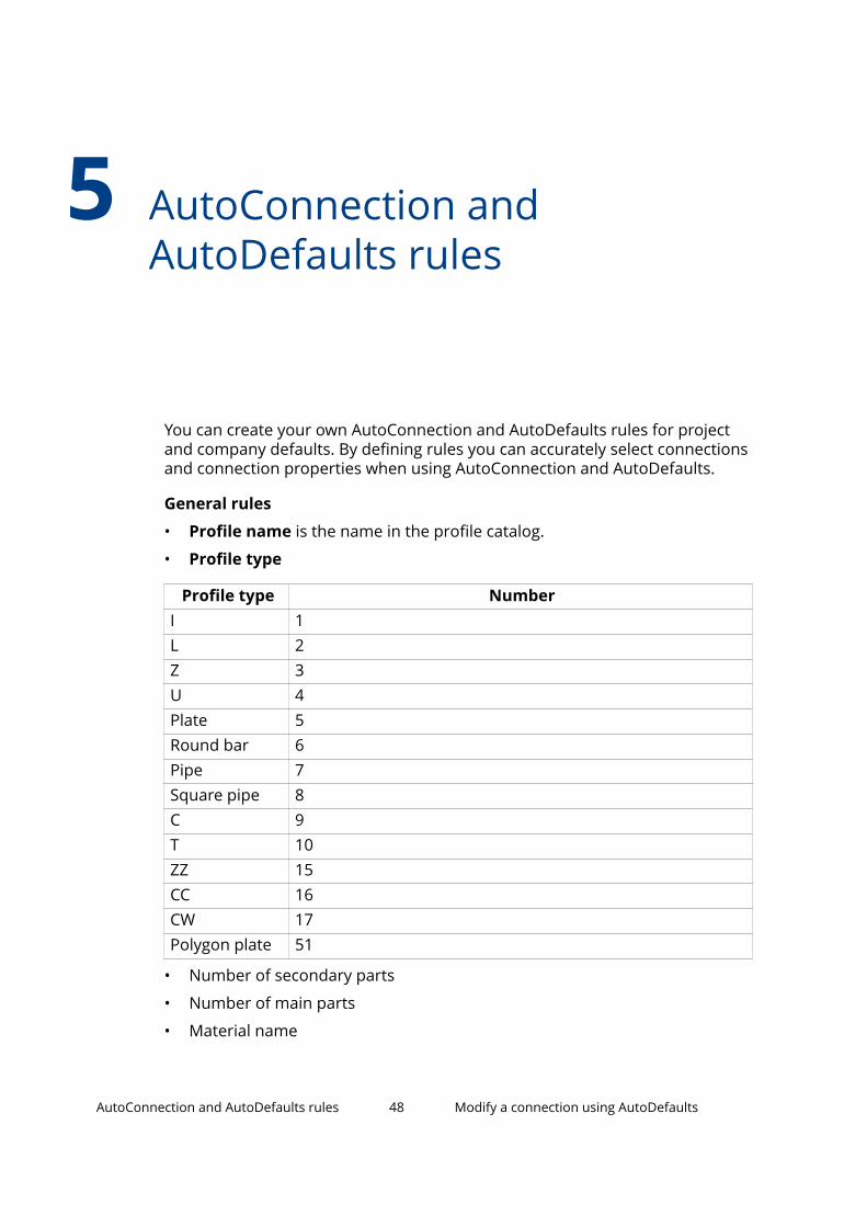
General rules
• Profile name is the name in the profile catalog.
• Profile type
Profile type NumberI 1L 2Z 3U 4Plate 5Round bar 6Pipe 7Square pipe 8C 9T 10ZZ 15CC 16CW 17Polygon plate 51
• Number of secondary parts
• Number of main parts
• Material name
AutoConnection and AutoDefaults rules 48 Modify a connection using AutoDefaults

Orientation rules
Depending on the relative angle of a beam, the connections can be classifiedas sloped, skewed, or cant. The angle value can be between - 90 and 90degrees.
• Sloped angle (relative to main part cross section)
The longitudinal axis of the secondary part follows the slope of thelongitudinal axis of the main part.
• Skewed angle (relative to main part longitudinal axis)
The longitudinal axis of the secondary part is skewed according to the mainpart cross section. The angle is the smaller of the angles between thelongitudinal axis of the secondary part and the main part Z or Y axis.
• Cant angle
For rotated secondary parts
Dimension rules
• Profile depth
• Web depth
For profiles with an upper and lower flange, the web depth is: h-t1-t2-2*r1Or, if t2 is zero: h-2*t-2*r1
AutoConnection and AutoDefaults rules 49 Modify a connection using AutoDefaults

For profiles with one flange, the web depth is h-t-r1-r2.
• Web thickness
• Flange thickness
Forces and strengths
• Shear force
• Axial force
• Bending moment
See also
Combining and iterating properties for AutoDefaults (page 50)
AutoDefaults example: Using iteration with connection check (page 52)
Using reaction forces and UDLs in AutoDefaults and AutoConnection(page 54)
5.1 Combining and iterating properties for AutoDefaultsCombining properties
You can save properties files that cover different groups of properties and usethese files to define many rules. For example, you can have one file for boltproperties and another for profile properties. AutoDefaults combines theseparate files into one file. This means that you can define fewer files becauseyou can use one file for several rules. If the files contain different values forthe same property, Tekla Structures uses the last property it finds, see theexample image below.
AutoConnection and AutoDefaults rules 50 Combining and iterating properties forAutoDefaults
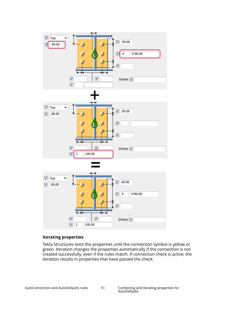
Iterating properties
Tekla Structures tests the properties until the connection symbol is yellow orgreen. Iteration changes the properties automatically if the connection is notcreated successfully, even if the rules match. If connection check is active, theiteration results in properties that have passed the check.
AutoConnection and AutoDefaults rules 51 Combining and iterating properties forAutoDefaults

Limitations
• Tekla Structures cannot iterate property files directly. Use a single iterationrule set with sub-rule sets.
• You cannot have many parallel iteration rule sets. Use a single iteration ruleset and place it just before the default rule set.
• Place the combination rule sets above the iteration rule set in theAutoDefaults tree structure.
• Combination rule sets can only be one level deep.
• Tekla Structures disregards empty rule sets, so include at least one rule ineach rule set.
See also
Create a rule set for AutoDefaults (page 44)
5.2 AutoDefaults example: Using iteration withconnection checkYou can use the connection check result when using AutoDefaults withiteration. If an iteration rule matches, but the connection does not pass theconnection check and the connection symbol remains red, AutoDefaultscontinues testing other rules and properties until the connection symbol isgreen.
In this example, you will create iteration rules to set the number of boltsaccording to the result of the connection check. After this, you will use the
AutoConnection and AutoDefaults rules 52 AutoDefaults example: Using iteration withconnection check

rules group and connection check together for a connection. The exampleimage below shows the rules in the AutoDefaults Setup dialog box.
To create iteration rules for use with connection check:
1. On the File menu, click Catalogs --> AutoDefaults settings.
2. Right-click the tree and select New Rule Group.
3. Click the new rule group and rename it to Iteration example.
4. Browse the Iteration example tree to find End plate (144), right-clickit, and select Create Additional Rule Sets.
5. Right-click the New rule set and select Edit Rule Set.
6. Change the rule set name to ITERATION.
7. Set the Parameter file(s) selection in rule set option to Iterate untilconnection symbol is green.
8. Click OK.
9. Right-click the ITERATION rule set and select Create Additional RuleSets.
10. Right-click the New rule set and select Edit Rule Set.
11. Change the rule set name to 2 bolts.
12. Select the rule Secondary 1 depth and set the minimum and maximumdepth values for two bolts.
13. Set the Parameter file(s) selection in rule set option to Usecombination of first parameters.
14. Click OK.
AutoConnection and AutoDefaults rules 53 AutoDefaults example: Using iteration withconnection check
15. Right-click the connection properties file standard.j144 under 2 boltsand select Select Connection Parameters.
16. Select a properties file for two bolts in the Attribute File List and clickOK.
TIP If there is no suitable properties file, you can create a new file. Right-click the standard.j144 file and select Edit ConnectionParameters. Save the needed properties and click Cancel to closethe dialog box. The saved properties are now available in theAttribute File List.
17. Click Apply to have the changes available in the connection dialog box.
18. Repeat steps 9 to 16 for other rule sets.
19. Open the End plate (144) dialog box.
20. Select <Defaults> from the list next to the Load button and click Load.
21. On the General tab, set the AutoDefaults rule group option to theIteration example you created.
22. On the Design type tab, set the Check connection option to Yes.
23. Enter the load from secondary members in the Shear, Tension, andMoment options.
24. Click OK.
See also
AutoDefaults settings (page 41)
Combining and iterating properties for AutoDefaults (page 50)
5.3 Using reaction forces and UDLs in AutoDefaults andAutoConnectionYou can set reaction forces for AutoConnection and AutoDefaults in the user-defined attributes of a part, and for AutoDefaults also on the Design tab in theconnection dialog box.
Reaction forces
When you use reaction forces in a rule and AutoDefaults is activated, TeklaStructures first searches for reaction forces in the corresponding connection’sproperties. If the properties do not contain reaction forces, Tekla Structuressearches the user-defined attributes of the secondary part of the connection.If Tekla Structures does not find forces there, you cannot use reaction forcerules.
Shear force calculation
AutoConnection and AutoDefaults rules 54 Using reaction forces and UDLs in AutoDefaultsand AutoConnection

If you have not given any reaction force values, shear force is calculated usingthe UDL (uniformly distributed load) shear force routine. The UDL calculationis mainly intended for use with imperial units. It uses the yield stress value,profile dimensions, and UDL percentage to calculate the maximum shear forceallowed.
• Yield stress is defined in the material catalog.
• Profile dimensions come from the profile catalog.
• UDL percentage is taken either from the connection dialog box or from anadvanced option.
Tekla Structures compares the result with the shear force rule in AutoDefaults.
To use UDLs for AutoConnection and AutoDefaults:
To Do thisUse UDL forAutoConnection
1. On the Design tab in the connection dialog box, set theUDL option to Yes.
2. Enter the UDL percentage in the UDL% box.
If you do not enter any value, Tekla Structures uses adefault percentage set with the XS_AUTODEFAULT_UDL_PERCENT advanced option.
Use UDL forAutoDefaults
1. On the Design tab in the connection dialog box, set theUse UDL option to Yes.
2. Enter the UDL percentage in the UDL % box.
If you do not enter any value, Tekla Structures uses adefault percentage set using the XS_AUTODEFAULT_UDL_PERCENT advanced option.
AutoConnection and AutoDefaults rules 55 Using reaction forces and UDLs in AutoDefaultsand AutoConnection

6 Disclaimer
© 2017 Trimble Solutions Corporation and its licensors. All rights reserved.
This Software Manual has been developed for use with the referencedSoftware. Use of the Software, and use of this Software Manual are governedby a License Agreement. Among other provisions, the License Agreement setscertain warranties for the Software and this Manual, disclaims otherwarranties, limits recoverable damages, defines permitted uses of theSoftware, and determines whether you are an authorized user of the Software.All information set forth in this manual is provided with the warranty set forthin the License Agreement. Please refer to the License Agreement for importantobligations and applicable limitations and restrictions on your rights. Trimbledoes not guarantee that the text is free of technical inaccuracies ortypographical errors. Trimble reserves the right to make changes andadditions to this manual due to changes in the software or otherwise.
In addition, this Software Manual is protected by copyright law and byinternational treaties. Unauthorized reproduction, display, modification, ordistribution of this Manual, or any portion of it, may result in severe civil andcriminal penalties, and will be prosecuted to the full extent permitted by law.
Tekla, Tekla Structures, Tekla BIMsight, BIMsight, Tekla Civil, Tedds, Solve,Fastrak and Orion are either registered trademarks or trademarks of TrimbleSolutions Corporation in the European Union, the United States, and/or othercountries. More about Trimble Solutions trademarks: http://www.tekla.com/tekla-trademarks. Trimble is a registered trademark or trademark of TrimbleInc. in the European Union, in the United States and/or other countries. Moreabout Trimble trademarks: http://www.trimble.com/trademarks.aspx. Otherproduct and company names mentioned in this Manual are or may betrademarks of their respective owners. By referring to a third-party product orbrand, Trimble does not intend to suggest an affiliation with or endorsementby such third party and disclaims any such affiliation or endorsement, exceptwhere otherwise expressly stated.
Portions of this software:
D-Cubed 2D DCM © 2010 Siemens Industry Software Limited. All rightsreserved.
Disclaimer 56 Using reaction forces and UDLs in AutoDefaultsand AutoConnection

EPM toolkit © 1995-2006 Jotne EPM Technology a.s., Oslo, Norway. All rightsreserved.
Open Cascade Express Mesh © 2015 OPEN CASCADE S.A.S. All rights reserved.
PolyBoolean C++ Library © 2001-2012 Complex A5 Co. Ltd. All rights reserved.
FLY SDK - CAD SDK © 2012 VisualIntegrity™. All rights reserved.
Teigha © 2002-2016 Open Design Alliance. All rights reserved.
CADhatch.com © 2017. All rights reserved.
FlexNet Publisher © 2014 Flexera Software LLC. All rights reserved.
This product contains proprietary and confidential technology, informationand creative works owned by Flexera Software LLC and its licensors, if any. Anyuse, copying, publication, distribution, display, modification, or transmission ofsuch technology in whole or in part in any form or by any means without theprior express written permission of Flexera Software LLC is strictly prohibited.Except where expressly provided by Flexera Software LLC in writing,possession of this technology shall not be construed to confer any license orrights under any Flexera Software LLC intellectual property rights, whether byestoppel, implication, or otherwise.
To see the third party open source software licenses, go to Tekla Structures,click File menu --> Help --> About Tekla Structures and then click the 3rdparty licenses option.
The elements of the software described in this Manual are protected byseveral patents and possibly pending patent applications in the United Statesand/or other countries. For more information go to page http://www.tekla.com/tekla-patents.
Disclaimer 57 Using reaction forces and UDLs in AutoDefaultsand AutoConnection

Disclaimer 58 Using reaction forces and UDLs in AutoDefaultsand AutoConnection

Index
Aapplications in Applications andComponents catalog ....................................25autoconnection............................................. 35
defining rules......................................37,38modifying rules........................................38rules..................................................... 35,48settings..................................................... 35using......................................................... 39
autodefaults...................................................41combining properties............................. 50connection check.................................... 52defining rules......................................43,44iterating properties................................. 50modifying properties.............................. 45rules..................................................... 41,48settings..................................................... 41using......................................................... 46using reaction forces...............................54using UDLs............................................... 54
Ccomponent catalog.......................................11components
conceptual................................................23converting................................................ 23
components in Applications & components.........................................................................11components
adding......................................................... 8adding a base plate.................................18adding a corbel connection................... 20adding a pad footing reinforcement.....21adding an end plate................................ 17catalog...................................................... 11
connecting beams to columns.............. 19connections................................................5creating component views..................... 10detailing...................................................... 5details......................................................... 5tips............................................................ 22viewing......................................................10
Eextensions in Applications and componentscatalog............................................................ 25extensions
importing..................................................31
Mmacros
adding.......................................................27editing.......................................................27global................................................... 25,27local......................................................25,27macro folder............................................ 25recording.................................................. 27running..................................................... 27
Ppublishing groups in Applications &components catalog..................................... 32
Rrecording
macros...................................................... 27running
macros...................................................... 27
59

60