Embed Size (px)
Citation preview

Tekla Structures 2016Basics of steel connections
April 2016
©2016 Trimble Solutions Corporation

Contents
1 Steel connection properties......................................................... 31.1 Parts in steel connections................................................................................31.2 Stiffeners............................................................................................................ 51.3 Haunch............................................................................................................... 81.4 Notch................................................................................................................ 101.5 BCSA notch....................................................................................................... 151.6 Bolts.................................................................................................................. 191.7 Beam cut.......................................................................................................... 261.8 Doubler plate................................................................................................... 301.9 Angle box..........................................................................................................321.10 Welds................................................................................................................ 371.11 General tab...................................................................................................... 381.12 Design and Design type tabs..........................................................................391.13 Analysis tab......................................................................................................41
2 Joints.def file................................................................................ 442.1 Using the joints.def file.................................................................................. 442.2 Example: How Tekla Structures uses the joints.def file............................. 472.3 General defaults in the joints.def file...........................................................482.4 Bolt diameter and number of bolts in the joints.def file........................... 492.5 Bolt and part properties in the joints.def file..............................................51
Gusset connection properties in the joints.def file........................................................... 53Diagonal connection properties in the joints.def file........................................................56Profile dependent bolt dimensions in the joints.def file.................................................. 57
3 Excel spreadsheets in connection design................................. 593.1 Files used in Excel spreadsheet connection design.................................... 593.2 Example of an Excel spreadsheet in connection design.............................613.3 Example of visualizing the Excel connection design process.....................653.4 Showing connection status in Excel connection design............................. 69
4 Disclaimer.....................................................................................70
2

1 Steel connection properties
Once you have created a frame of parts in your Tekla Structures model, youwill need to connect the parts to complete the model.
This section explains the properties that are common to many different TeklaStructures connections.
See also
Parts in steel connections (page 3)
Stiffeners (page 5)
Haunch (page 8)
Notch (page 10)
BCSA notch (page 15)
Bolts (page 19)
Beam cut (page 26)
Doubler plate (page 29)
Angle box (page 32)
Welds (page 37)
General tab (page 38)
Design and Design type tabs (page 39)
Analysis tab (page 41)
1.1 Parts in steel connectionsUse the Parts or Plates tab to define the parts that Tekla Structures createsfor a steel connection.
Steel connection properties 3 Parts in steel connections

Some connections have all the parts on one Parts or Plates tab. Otherconnections have separate tabs for the parts. See the example images below.
One tab forall parts
Separatetabs forparts
Property DescriptionThickness (t),width (b),height (h)
Define the thickness, width and height of the parts.
For some connection types, you do not have to enter theseproperties. For example, in end plate connections, TeklaStructures calculates the width and height by using thenumber of bolts and bolt edge distances.
You can delete a part by entering zero (0) as the thickness.Profile Select a suitable profile from the profile catalog, or enter a
profile name.Part positionnumber(Pos_No)
The part position number consists of a prefix and a startnumber.
1. Prefix
2. Start number
Some connections have a second row for the part positionnumber where you can enter the assembly position number.
The part position number defined in the connection dialogbox overrides the settings defined in the Componentssettings in File menu --> Settings --> Options.
Material Select a suitable material from the material catalog.Name Define a name that is shown in drawings and reports.
Steel connection properties 4 Parts in steel connections

1.2 StiffenersUse the Stiffeners tab to define stiffener properties in steel connections.Stiffeners are used to strengthen a steel beam or a column. Stiffeners areusually plates.
Stiffener plate dimensions
Part DescriptionTop NS Define the top near side stiffener thickness, width and height.Top FS Define the top far side stiffener thickness, width and height.Bottom NS Define the bottom near side stiffener thickness, width and
height.Bottom FS Define the bottom far side stiffener thickness, width and
height.
Option Description DefaultPos_No Define a prefix and a start
number for the part positionnumber.
The default part start number isdefined in the Componentssettings in File menu --> Settings --> Options.
Material
Define the material grade. The default material is defined inthe Part material box in theComponents settings in File menu--> Settings --> Options.
Name Define a name that is shownin drawings and reports.
Finish Define how the part surface istreated.
Stiffener orientation
Option DescriptionCreates stiffeners parallel to the secondary part.
Creates stiffeners perpendicular to the main part.
Stiffener creation
Steel connection properties 5 Stiffeners

Option DescriptionStiffeners are not created.
Creates stiffeners.
For some components, you can also:
• Select the option that Tekla Structures determines thesize of the stiffener based on the shear tab size. TeklaStructures attempts to keep the bottom edges of thestiffener plate and shear tab on the same level, ifpossible.
• Create a partial stiffener that leaves a gap between thestiffener plate and the bottom flange of the main part.
Stiffener shape
Option DescriptionCreates square stiffener plates with a gap for the main partweb rounding.
Creates stiffener plates with line chamfers.
Stiffener gap
Option DescriptionDefine the size of the gap between the main part flangesand the stiffener.
For some components, you can also define:
• The distance from the edge of the flange to the edge ofthe stiffener
• The vertical dimension of the stiffener line chamfer
• The horizontal dimension of the stiffener chamfer or theradius of an arc type chamfer
Stiffener chamfer dimensions
Steel connection properties 6 Stiffeners

Description1 Vertical dimension2 Horizontal dimension
Stiffener chamfer types
Option DescriptionNo chamfer
Line chamfer
Convex arc chamfer
Concave arc chamfer
Stiffener position
Steel connection properties 7 Stiffeners
Description1 Gap between the stiffener and the beam web edge2 Gap between the top near side stiffener and the beam flange edge3 Gap between the bottom near side stiffener and the beam flange edge4 Gap between the bottom far side stiffener and the beam flange edge5 Gap between the top far side stiffener and the beam flange edge
By default, Tekla Structures positions the edges of the stiffener level with theflanges of the secondary part.
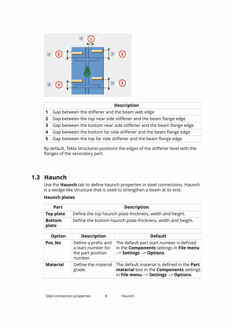
1.3 HaunchUse the Haunch tab to define haunch properties in steel connections. Haunchis a wedge-like structure that is used to strengthen a beam at its end.
Haunch plates
Part DescriptionTop plate Define the top haunch plate thickness, width and height.Bottomplate
Define the bottom haunch plate thickness, width and height.
Option Description DefaultPos_No Define a prefix and
a start number forthe part positionnumber.
The default part start number is definedin the Components settings in File menu--> Settings --> Options.
Material Define the materialgrade.
The default material is defined in the Partmaterial box in the Components settingsin File menu --> Settings --> Options.
Steel connection properties 8 Haunch

Option Description DefaultName Define a name that
is shown indrawings andreports.
Finish Define how the partsurface is treated.
Haunch plate creation
Option DescriptionCreates top and bottom haunch plates.
To create a single plate, enter 0 as the thickness for theplate that is not created.
Haunch plates are not created.
Haunch plate chamfers
Description1 Width of the top haunch plate chamfer2 Height of the top haunch plate chamfer3 Height of the bottom haunch plate chamfer4 Width of the bottom haunch plate chamfer
Steel connection properties 9 Haunch

1.4 NotchUse the Notch tab to define notch properties in steel connections. The Notchtab has separate options for automatic and manual notching. You can createnotches for the secondary beam.
Automatic notching
Automatic notching options affect both the top and the bottom flange.
Notch shape
Option DescriptionCreates notches to the secondary beam. The cuts aresquare to the main beam web.
Creates notches to the secondary beam. The cuts aresquare to the secondary beam web.
Creates notches to the secondary beam. The vertical cutis square to the main beam, and the horizontal cut issquare to the secondary beam.Automatic notching is not in use.
Creates notches to both flanges of the secondary beam.The cuts are square to the secondary beam.
Notch size
Option DescriptionMeasures the notch size from the edge of the mainbeam flange and from underneath the top flange of themain beam.Measures the notch size from the center line of themain beam and from the top flange of the main beam.
Define horizontal and vertical values for the cuts:
Flange cut shape
Option DescriptionCuts the secondary beam flange parallel to the mainbeam.
Steel connection properties 10 Notch
Option DescriptionCuts the secondary beam flange square.
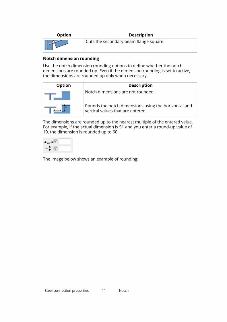
Notch dimension rounding
Use the notch dimension rounding options to define whether the notchdimensions are rounded up. Even if the dimension rounding is set to active,the dimensions are rounded up only when necessary.
Option DescriptionNotch dimensions are not rounded.
Rounds the notch dimensions using the horizontal andvertical values that are entered.
The dimensions are rounded up to the nearest multiple of the entered value.For example, if the actual dimension is 51 and you enter a round-up value of10, the dimension is rounded up to 60.
The image below shows an example of rounding:
Steel connection properties 11 Notch

Description1 Before rounding2 Tekla Structures applies the horizontal and vertical rounding values.3 After rounding
Notch position
Option DescriptionCreates the cut below the main beam flange.
Creates the cut above the main beam flange.
Notch chamfer
Option DescriptionThe notch is not chamfered.
Steel connection properties 12 Notch

Option DescriptionCreates a notch with a line chamfer.
Creates a notch with a chamfer according to the radiusthat you enter.
Enter a radius for the chamfer.
Manual notching
Use manual notching when a part that does not belong to the connectionclashes with the secondary beam. When you use manual notching, theconnection creates cuts using the values that you enter on the Notch tab. Youcan use different values for the top and the bottom flange.
Side of flange notch
Option DescriptionCreates notches on both sides of the flange.
Creates notches on the near side of the flange.
Creates notches on the far side of the flange.
Cut dimensions
Description1 Dimensions for the horizontal flange cuts. The default is 10 mm.
Steel connection properties 13 Notch

Description2 Dimensions for the vertical flange cuts.
The gap between the notch edge and the beam flange is equal to themain part web rounding. The notch height is rounded up to the nearest 5mm.
Flange notch shape
Option DescriptionCreates chamfers in the flange.
If you do not enter a horizontal dimension, a chamfer of45 degrees is created.Creates cuts to the flange with the default values unless
you enter values for the horizontal and vertical dimensions, see the image of cut dimensions above.The flange is not cut.
Creates cuts to the flange according to the horizontal
dimension to make it flush with the web, see theimage of cut dimensions above.
Creates cuts to the flange according to the horizontal
and vertical dimensions, see the image of cutdimensions above.
Flange notch depth
Option DescriptionDefines the flange notch depth.
Defines the flange notch depth with a dimension from thesecondary beam web center line to the edge of the notch.
Dimension from web to flange cut
Steel connection properties 14 Notch

Description1 Distance between the web and the flange cut
1.5 BCSA notchUse the Notch tab to define notch properties in steel connections. BCSAnotches are created according to British Constructional Steelwork Association(BCSA) specifications. You can create notches for the secondary beam.
Notch shape for the top and the bottom of the secondary beam
You can select from the BCSA notch def list whether the notch is createdaccording to BCSA specifications.
Option DescriptionDefault Define the notch dimensions.Yes Creates a 50 mm notch for simple beam-to-beam
connections.No The component uses the options on the Notch tab to
define the notch dimensions.
Notch dimensions
Define the top and the bottom dimensions of the notch if you have set theBCSA notch def option to No.
Steel connection properties 15 BCSA notch

Description1 Vertical notch dimension2 Horizontal notch dimension
Notch shape
Option Option DescriptionNotch is not created.
Creates a square notch on the topside or on the bottom side of thesecondary beam.
You can define the notchdimensions. In beam-to-beamconnections with a slopedsecondary beam, the depth ismeasured as shown in the image.
Creates a notch on both sides ofthe secondary beam.
You can define the notchdimensions.Creates a chamfered notch onboth sides of the secondarybeam.
You can define the chamferdimensions.Creates a strip.
You can define the length of thestrip. The flanges are cutcompletely.Creates a special type of squarenotch.
You can define the notchdimensions. The notch is squareto the secondary beam. There are
Steel connection properties 16 BCSA notch

Option Option Descriptionno default values for the length orthe depth.
Notching side
Option DescriptionCreates notches on both sides.
Creates a notch on the left side.
Creates a notch on the right side.
Notch dimensions
Define the top and the bottom dimensions of the notch if you have set theBCSA notch def option to No.
Description1 Vertical notch dimension2 Horizontal notch dimension
Notch shape
Option Option DescriptionNotch is not created.
Steel connection properties 17 BCSA notch

Option Option DescriptionCreates a square notch on the topside or on the bottom side of thesecondary beam.
You can define the notchdimensions. In beam-to-beamconnections with a slopedsecondary beam, the depth ismeasured as shown in the image.
Creates a notch on both sides ofthe secondary beam.
You can define the notchdimensions.Creates a chamfered notch onboth sides of the secondarybeam.
You can define the chamferdimensions.Creates a strip.
You can define the length of thestrip. The flanges are cutcompletely.Creates a special type of squarenotch.
You can define the notchdimensions. The notch is squareto the secondary beam. There areno default values for the length orthe depth.
Notching side
Option DescriptionCreates notches on both sides.
Steel connection properties 18 BCSA notch

Option DescriptionCreates a notch on the left side.
Creates a notch on the right side.
1.6 BoltsUse the Bolts tab to define bolt properties in steel connections.
Bolt basic properties
Option Description DefaultBolt size Define the bolt
diameter.The available sizes are defined in thebolt assembly catalog.
Bolt standard Select the boltstandard from thebolt assemblycatalog.
Tolerance Define the gapbetween the boltand the hole.
Thread in mat Define the threadwithin the boltedparts when bolts areused with a shaft.
This has no effectwhen full-threadedbolts are used.
Yes
Site/Workshop Define the locationwhere the boltsshould be attached.
Site
Slotted holes
Holes can be slotted, oversized, or tapped.
Steel connection properties 19 Bolts

Description1 Vertical dimension
The default value 0 creates a round hole.2 Horizontal dimension, or the allowance for oversized holes.
The default value 0 creates a round hole.
Option DescriptionHole type Slotted creates slotted holes.
Oversized creates oversized or tapped holes.Rotate Slots When the hole type is Slotted, this option rotates the
slotted holes.Slots in Part(s) in which slotted holes are created. No creates
round holes.
The image below shows an example of slotted hole length:
Bolt group dimensions
You can define the bolt group dimensions to control the size and position ofthe end plate. You can also delete bolts from the bolt group. The exampleimage below shows the bolt group dimensions of the End plate (144)connection.
Steel connection properties 20 Bolts

Description1 Dimension for the horizontal bolt group position2 Select how the dimensions for the horizontal bolt group position are
measured:
• Left: From the left edge of the secondary part to the leftmost bolt.
• Middle: From the center line of the secondary part to center line ofthe bolts.
Steel connection properties 21 Bolts

Description
• Right: From the right edge of the secondary part to the rightmostbolt.
3 Bolt edge distance
Edge distance is the distance from the center of a bolt to the edge ofthe part.
4 Number of bolts5 Bolt spacing
Use a space to separate bolt spacing values. Enter a value for each
space between bolts. For example, if there are 3 bolts , enter 2
values .
The image below shows the bolt group layout:
Steel connection properties 22 Bolts

Description
6 Dimension for the vertical bolt group position7 Select how the dimensions for vertical bolt group position are
measured:
• Top: From the upper edge of the secondary part to the uppermostbolt
• Middle: From the center line of the bolts to the center line of thesecondary part
• Below: From the lower edge of the secondary part to the lowestbolt
Steel connection properties 23 Bolts
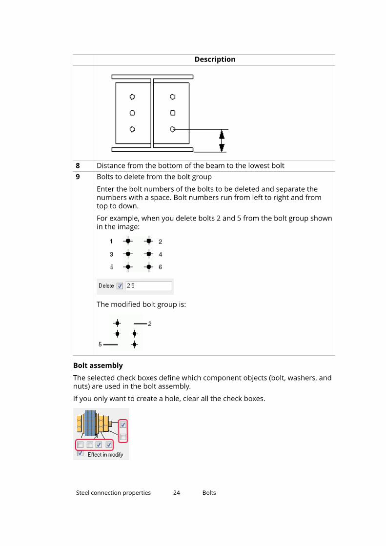
Description
8 Distance from the bottom of the beam to the lowest bolt9 Bolts to delete from the bolt group
Enter the bolt numbers of the bolts to be deleted and separate thenumbers with a space. Bolt numbers run from left to right and fromtop to down.
For example, when you delete bolts 2 and 5 from the bolt group shownin the image:
The modified bolt group is:
Bolt assembly
The selected check boxes define which component objects (bolt, washers, andnuts) are used in the bolt assembly.
If you only want to create a hole, clear all the check boxes.
Steel connection properties 24 Bolts

To modify the bolt assembly in an existing component, select the Effect inmodify check box and click Modify.
Bolt length increase
You can increase the bolt length. Use this option when, for example, paintingrequires the bolt length to be increased. Tekla Structures uses the value in boltlength calculation.
Staggering of bolts
You can use different bolt group patterns.
Option
Staggering of bolts on clip angles
Option DescriptionBolts are not staggered.
The bolts that connect the clip angle to the secondarypart are on the same horizontal level as the bolts thatconnect the clip angle to the main part.Bolts on the main part are staggered.
The bolts that connect the clip angle to the main part aremoved downwards by half the bolt vertical spacing value.Bolts on the secondary part are staggered.
The bolts that connect the clip angle to the secondarypart are moved downwards by half the bolt verticalspacing value.
Steel connection properties 25 Bolts

Option DescriptionBolts on the secondary part are staggered.
The bolts that connect the clip angle to the slopedsecondary part are parallel to the secondary part.
Bolt group orientation
Option DescriptionBolts are staggered in the direction of the secondarypart.
Square bolt group is positioned horizontally.
Square bolt group is sloped in the direction of thesecondary part.
1.7 Beam cutUse the Beam cut tab to define the properties of weld access holes, beam endpreparations, and flange cuts in steel connections.
Weld backing bar
Part DescriptionWeld backingbar
Define the weld backing bar thickness and width.
Option Description DefaultPos_No Define a prefix and a
start number for thepart positionnumber.
Some componentshave a second row ofboxes where you canenter the assemblyposition number.
The default part start number isdefined in the Components settingsin File menu --> Settings -->Options.
Material Define the materialgrade.
The default material is defined inthe Part material box in theComponents settings in File menu--> Settings --> Options.
Steel connection properties 26 Beam cut

Option Description DefaultName Define a name that
is shown in drawingsand reports.
Finish Define how the partsurface is treated.
Weld access hole dimensions
Description1 Gap between the secondary part top flange and the main part2 Vertical dimensions for the top and the bottom weld access holes3 Horizontal dimensions for the top and the bottom weld access holes4 Gap between the secondary part web and the main part
Tekla Structures adds the value you enter here to the gap you enter onthe Picture tab of the component.
5 Gap between the secondary part bottom flange and the main part
Tekla Structures adds the value you enter here to the gap you enter onthe Picture tab of the component.
Weld access holes
Option DescriptionCreates a round weld access hole.
Creates a square weld access hole.
Steel connection properties 27 Beam cut

Option DescriptionCreates a diagonal weld access hole.
Creates a round weld access hole with a radius that you
can define in .
Creates an extended cone-shaped weld access hole with aradius and dimensions that you can define in
and .Creates a cone-shaped weld access hole with radiuses
that you can define in and .
Capital R defines the large radius (height). The default is R= 35.
Small r defines the small radius. The default is r = 10.
Beam end preparation
Option DescriptionBeam end is not prepared.
Creates preparation to the top and the bottom flange.
Creates preparation to the top flange.
Creates preparation to the bottom flange.
Flange cut
Option DescriptionFlange is not cut.
Cuts the flange.
Steel connection properties 28 Beam cut

Weld backing bars
Option Option DescriptionBacking bars are not created.
Creates backing bars inside the flanges.
Creates backing bars outside the flanges.
Weld backing bar length
Option DescriptionAbsolute length of the backing bar
Extension beyond the edge of the flange
Weld backing bar position
Option DescriptionPositive or negative value to move the front end of thebacking bar relative to the end of the flange
Assembly type
Assembly type defines the location where the weld backing bar welds aremade. The Workshop option includes the backing bars in the assembly.
Steel connection properties 29 Doubler plate

1.8 Doubler plateUse the Doubler plate tab to define doubler plate properties in steelconnections. Doubler plates are used to strengthen the web of the main part.Tekla Structures does not create them by default.
Web plate
Part DescriptionWeb plate Define the web plate thickness and height.
Option Description DefaultPos_No Define a prefix and a
start number for thepart positionnumber.
The default part start number is definedin the Components settings in File menu--> Settings --> Options.
Material Define the materialgrade.
The default material is defined in the Partmaterial box in the Componentssettings in File menu --> Settings -->Options.
Name Define a name that isshown in drawingsand reports.
Doubler plates
Option DescriptionDoubler plates are not created.
Creates a doubler plate on the far side.
Creates a doubler plate on the near side.
Creates doubler plates on both sides.
Doubler plate edge shape
Steel connection properties 30 Doubler plate

Option DescriptionCreates bevel doubler plates using the angle defined in
.
Creates square doubler plates.
Dimensions
Description1 Edge distance from the column flange2 Doubler plate edge distance
Edge distance is the distance from the center of a hole to the edge of thepart.
3 Edge distance of the doubler plate in relation to the bottom of thesecondary part
4 Number of holes
Steel connection properties 31 Doubler plate

Description5 Hole spacing
Use a space to separate hole spacing values. Enter a value for eachspace between holes. For example, if there are 3 holes, enter 2 values.
Weld hole size
Description1 Hole diameter2 Slot length3 Slot width
1.9 Angle boxUse the Angle box tab to define the properties of seat angles in steelconnections.
Seat angle
The purpose of seat angles is to carry loads from the secondary part. Seatangles can be positioned to top, bottom or both flanges of the secondary part.The seat angle can be stiffened, and bolted or welded to the main andsecondary parts. The Angle profile box (170) connection and Angle profilebox (1040) detail create seat angles by default.
Part DescriptionStiffeners Define the stiffener thickness, width and height.Profile Define the seat angle profile by selecting it from the profile
catalog.
Option Description DefaultPos_No Define a prefix and a
start number for theThe default part start number is defined inthe Components settings in File menu -->Settings --> Options.
Steel connection properties 32 Angle box

Option Description Defaultpart positionnumber.
Material Define the materialgrade.
The default material is defined in the Partmaterial box in the Components settingsin File menu --> Settings --> Options.
Name Define a name that isshown in drawingsand reports.
Finish Define how the partsurface is treated.
Seat angle position
Option DescriptionSeat angle is not created.
Creates a seat angle at the top of the flange.
Creates a seat angle at the bottom of the flange.
Creates seat angles on both sides of the flange.
Seat angle attachment
Seat angle is positioned at the top or at the bottom of the secondary part.
Steel connection properties 33 Angle box

Option Option DescriptionSeat angle is bolted to the mainpart and to the secondary part.
Seat angle is welded to the mainpart and bolted to thesecondary part.
Seat angle is bolted to the mainpart and welded to thesecondary part.
Seat angle is welded to the mainpart and to the secondary part.
Seat angle offset
Description1 Horizontal offset from the center line of the main part
Stiffener type
Option DescriptionCreates a rectangular stiffener plate.
Creates a triangular stiffener plate.
Steel connection properties 34 Angle box

Option DescriptionThe line connecting the ends of the seat angle legsdefines the stiffener plate shape.
Seat angle rotation
Option DescriptionSeat angle is not rotated.
Rotates the seat angle 90 degrees horizontally.
The Middle stiffeners option in the Middle stiffenerposition list stiffens the rotated seat angle.
Seat angle orientation
Option DescriptionConnects the longer leg of the seat angle to thesecondary part.
Connects the longer leg of the seat angle to the mainpart.
Side stiffener position
Option DescriptionSide stiffeners are not created.
Creates side stiffeners on the near side.
Creates side stiffeners on the far side.
Creates stiffeners on the near side and the far side.
Middle stiffener position
Steel connection properties 35 Angle box

Option DescriptionMiddle stiffener plate is not created.
Creates the stiffener plate in the middle of the seatangle.
Enter the number of middle stiffeners in the Number ofmiddle stiffeners box.
Multiple stiffeners are centered and equally spaced.Creates the stiffener plate between the bolts in themiddle of the bolt spacing.
By default, stiffener is created between every two bolts.
Enter the number of middle stiffeners in the box belowthe option.
Gap
Description1 Top gap and bottom gap between the seat angle and the secondary part
Chamfer dimensions
Description1 Vertical dimension of the chamfer2 Horizontal dimension of the chamfer
Steel connection properties 36 Angle box

Chamfer type
Option DescriptionNo chamfer
Line chamfer
Convex arc chamfer
Concave arc chamfer
1.10 WeldsYou can define the properties of the welds used in components. TeklaStructures displays the appropriate weld dialog box when you click the Weldsbutton in the component properties dialog box.
The example image shows each weld definition using a number for the Bentgusset (140) connection. For each weld definition, use the upper row to define
Steel connection properties 37 Welds

the above-line properties of the weld, and the lower row for the below-lineproperties.
1.11 General tabThe General tab is available in steel connections and steel details.
Option DescriptionUp direction Rotates the connection around the secondary part or the
detail around the main part.
You can define the rotation angle around the x- and y-axisof the secondary part. The upper box is for the y-axis andthe lower box for the x-axis.
Position inrelation toprimary part
Available only for details. The check boxes next to theimages indicate the position of the definition point of thedetail, relative to the main part.
Horizontal offset and Vertical offset define thehorizontal and vertical alignment of the detail, relative tothe main part.
Locked Prevents modifications.Class A number given to all parts the connection creates. You
can use class to define the color of the parts in the model.Connectioncode
Identifies the connection. Tekla Structures can display thisconnection code in connection marks in drawings.
Steel connection properties 38 General tab

Option DescriptionAutoDefaultsrule group
Automatically sets connection properties according to theselected rule group. Rule group None switchesAutoDefaults off.
AutoConnection rule group
Automatically switches the connection to anotheraccording to the selected rule group.
1.12 Design and Design type tabsSome component dialog boxes include a Design tab, others include a Designtype tab. You can use the options on these tabs to check if the component willbear the uniform distributed load (UDL). Some Design tabs include only thedesign check. Tekla Structures saves the design summary as a .txt file in themodel folder.
You can use AutoDefaults rule groups and Excel files in the design check:
• AutoDefaults rule groups automatically modify component properties totake the calculated load. To define which AutoDefaults rule group to use, goto the General tab and select the rule in the AutoDefaults rule group listbox.
For more information, see Using reaction forces and UDLs in AutoDefaultsand AutoConnection.
• The information in an Excel file checks the connection design andautomatically updates component properties to bear the UDL. This isuseful when you want to check connection design according to otherdesign codes. See Excel spreadsheets in connection design (page 59).
Design tab
This design check is intended to be used with imperial units.
To check the design:
1. Go to the Design tab and select Yes in the Use UDL list.
2. To use information in an Excel spreadsheet in the UDL calculation, selectExcel in the External design list.
3. Enter the information you want to use in the calculation.
4. Select the connection in the model and click Modify.
Tekla Structures checks the component. A green component symbolindicates that the connection will bear the UDL, red indicates that it willnot.
Steel connection properties 39 Design and Design type tabs

5. To view the results of the check, right-click the component symbol andselect Inquire from the pop-up menu.
The Inquire Object dialog box shows the summary of the design checkand related information.
See also Excel spreadsheets in connection design (page 59).
Design type tab
This design check is intended to be used with imperial units.
To check the design:
1. Go to the Design type tab and select Yes in the Check connection list.
Tekla Structures checks the connection each time it is used or changed inthe model.
2. Enter the information you want to use in the calculation.
3. Select the connection in the model and click Modify.
Tekla Structures checks the component. A green component symbolindicates that the connection will bear the UDL, red indicates that it willnot.
4. To view the results of the check, right-click the component symbol andselect Inquire from the pop-up menu.
The Inquire Object dialog box shows the summary of the design check:the part checked, the name of the check, the applied and allowed forceand how much capacity has been used, the results and possible solutions.
Design tab for check design only
The design is based on the British standard BS5950.
The design has the following limitations:
• Design only works in the UK environment.
• Design is available only if the main part and the secondary parts areperpendicular.
• Design is available only with two bolts horizontally.
• Design is available only when vertical bolts are defined from the top.
• Design is valid for I profiles only.
To check the design:
1. Go to the Design tab and select On in the Design list.
2. Enter the Tie force in kilo Newtons (kN).
Tie force is required if the design check is turned on and the framing typeof the connection is beam-to-column. If there is no tie force, enter 0.
Steel connection properties 40 Design and Design type tabs

3. Enter the Shear force in kN.
If the design check is turned on, enter a positive value. If there is no shearforce, enter 0.
4. Select the connection in the model and click Modify.
The connection symbol shows the design check status:
• Green means that the design check was successful.
• Yellow means that a warning occurred in the design check.
• Red means that a fatal error occurred in the design check.
5. To view the results of the check, right-click the connection symbol andselect Inquire from the pop-up menu.
The Inquire Object dialog box shows the summary of the design checkand related information.
NOTE If the message Numbering not up to date is shown in the InquireObject dialog box, the marks will not be correct. You need torenumber the model to ensure that the marks are up-to-date. Afterthat use the Inquire command again to get the correct marks to thedesign check summary.
1.13 Analysis tabUse the Analysis tab in the steel connection or detail dialog box to define howTekla Structures handles connections and details in the analysis.
Steel connection properties 41 Analysis tab

Option DescriptionUse analysis restraints Set to Yes to use the analysis properties of the
connection or detail in the analysis instead ofthe analysis properties of the parts in theconnection.
You also need to set Member end releasemethod by connection to Yes in the AnalysisModel Properties dialog box when you createthe analysis model.
For more information, see Analysis modelproperties.
Member selection Use to associate the analysis properties witheach connection part (Primary, 1. secondary, 2.secondary, and so on).
Restraint combination For more information, see Defining supportconditions.Support condition
Longitudinal memberoffset
For more information, see Analysis partproperties.
Analysis profile Tekla Structures uses this profile in the analysisinstead of the one in the physical model to take
Steel connection properties 42 Analysis tab

Option Descriptionthe stiffness of the connection or detail intoaccount.
Analysis profile length In the analysis, Tekla Structures overrides theprofile of the part in the physical model for thislength.
Steel connection properties 43 Analysis tab

2 Joints.def file
The joints.def file contains general connection settings and connection-specific settings for different connection types. You can use the joints.deffile to set the default properties for different connection types. Joints.def isa text file that you can open and edit in any standard text editor.
Tekla Structures uses the values defined in the joints.def file for theproperties that do not have values in the connection dialog boxes. If youmanually enter values in the connection dialog boxes, the manually enteredvalues are used instead of the values in the joints.def file. AutoDefaultsalso override the values defined in the joints.def file.
By default, Tekla Structures stores the joints.def file in the \system folder.Tekla Structures searches for the joints.def file in the standard searchorder: model, project, firm, and system folder.
See also
Using the joints.def file (page 44)
Example: How Tekla Structures uses the joints.def file (page 46)
General defaults in the joints.def file (page 47)
Bolt diameter and number of bolts in the joints.def file (page 49)
Bolt and part properties in the joints.def file (page 51)
2.1 Using the joints.def fileThe joints.def file contains general connection settings and connection-specific settings for different connection types in separate sections. You canmodify the joints.def file using any standard text editor.
When you modify the file:
• Enter absolute values or names.
• Do not use feet and inch symbols.
Joints.def file 44 Using the joints.def file

• Ensure that the profiles exist in the profile catalog.
• Ensure that the bolts exist in the bolt catalog.
• You can set the measurement units at the beginning of the file.
• You can define in the JOINTDEFAULT line whether Tekla Structures usesthe default values in the joints.def file or the system default values, forexample, as follows:
• Value 1 means that the default values defined in the joints.def fileare used.
• Value 0 means that the system default values are used.
• The // characters at the beginning of a line mean that the line is acomment line. Tekla Structures does not use the information on theselines.
• You can force Tekla Structures to use the system default for a particularproperty by entering the value -2147483648 for the property.
Connection-specific properties
The properties for clip angles, shear tabs, end plates, gusset connections anddiagonal connections are in separate sections. Each section begins with aheader row that contains the column labels, for example as follows:
joints.def
Do not add columns to the file. If Tekla Structures cannot find a property in theconnection-specific section, it searches for the default property in the generaldefaults section.
Connections that use the joints.def file
The following connections use the joints.def file:
• Welded gusset (10)
• Bolted gusset (11)
• Bracing cross (19)
• Tube gusset (20)
• Tube crossing (22)
• Two sided angle cleat (25)
• Corner tube gusset (56)
• Corner bolted gusset (57)
• Wraparound gusset (58)
Joints.def file 45 Using the joints.def file
• Hollow brace wraparound gusset (59)
• Wraparound gusset cross (60)
• Wrapped cross (61)
• Gusseted cross (62)
• Corner wrapped gusset (63)
• Beam with stiffener (129)
• Column with shear plate (131)
• Bolted moment connection (134)
• Clip angle (141)
• Two sided end plate (142)
• Two sided clip angle (143)
• End plate (144)
• Shear plate simple (146)
• Welded to top flange (147)
• Welded to top flange S (149)
• Moment connection (181)
• Column with stiffeners W (182)
• Full depth (184)
• Full depth S (185)
• Column with stiffeners (186)
• Column with stiffeners S (187)
• Column with stiffeners (188)
• Shear plate tube column (189)
• Bent plate (190)
See also
General defaults in the joints.def file (page 47)
Example: How Tekla Structures uses the joints.def file (page 46)
Bolt diameter and number of bolts in the joints.def file (page 49)
Bolt and part properties in the joints.def file (page 51)
Joints.def file 46 Example: How Tekla Structures uses the joints.deffile

2.2 Example: How Tekla Structures uses the joints.def fileThis example explains how Tekla Structures calculates the bolt diameter andother properties of the Bolted gusset (11) connection using the joints.deffile.
The height of the diagonal profile is 10". Tekla Structures calculates the boltsize and the number of bolts according to the profile height. It searches the BOLTHEIGHT rows for a profile height of 10".
As the profile height is greater than 8.0 but under 12.0, Tekla Structures usesthe row with profile height 8.0. This sets the bolt diameter to 0.75.
Tekla Structures uses the bolt diameter to assign the bolt and part properties.It searches the DIAGBOLTPART rows for bolt diameter 0.75.
The following property values are used:
Bolt diameter 0.75Number ofboltshorizontally
2
Edge distancehorizontally
1.5
Edge distancevertically
1.5
Distancebetween boltshorizontally
2.5
Distancebetween boltsvertically
System default is used.
Tekla Structures does not use the connection plate thickness or angle profileproperties in this connection.
Joints.def file 47 General defaults in the joints.def file
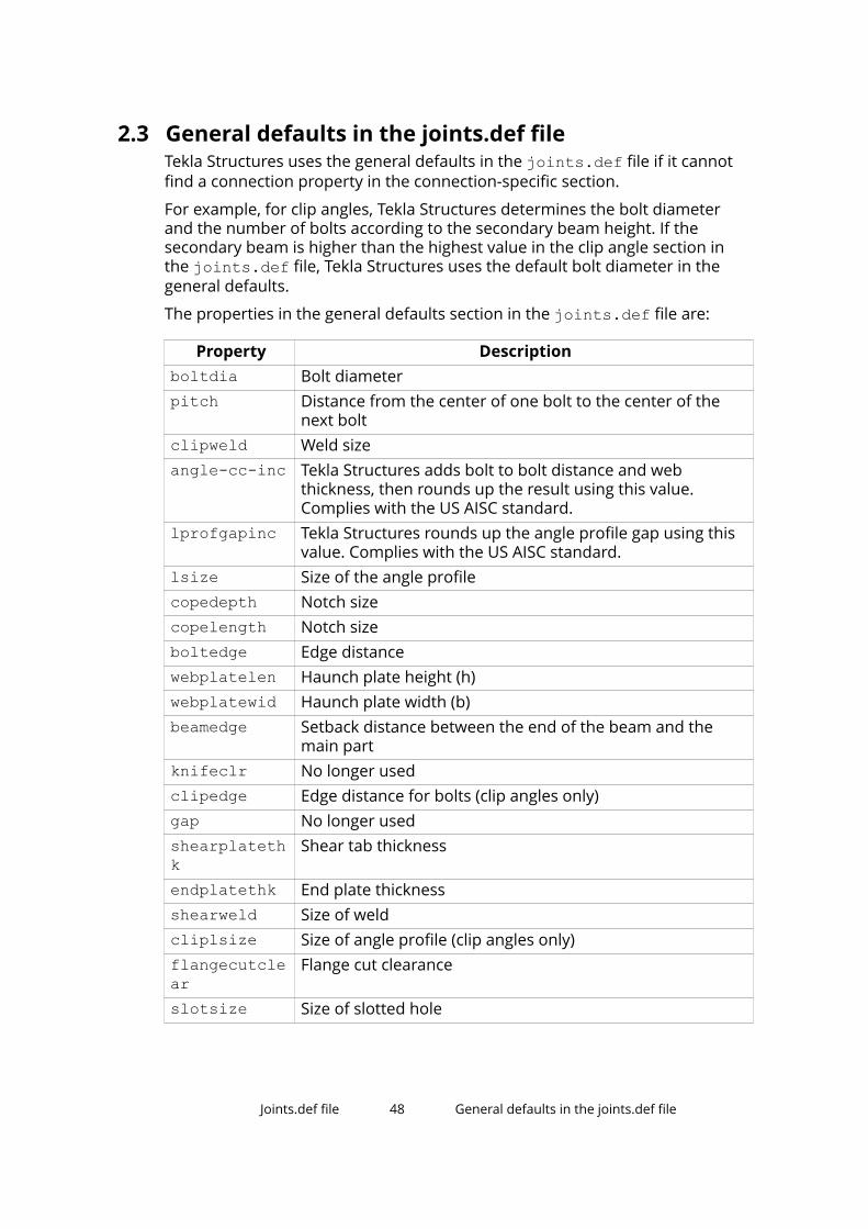
2.3 General defaults in the joints.def fileTekla Structures uses the general defaults in the joints.def file if it cannotfind a connection property in the connection-specific section.
For example, for clip angles, Tekla Structures determines the bolt diameterand the number of bolts according to the secondary beam height. If thesecondary beam is higher than the highest value in the clip angle section inthe joints.def file, Tekla Structures uses the default bolt diameter in thegeneral defaults.
The properties in the general defaults section in the joints.def file are:
Property Descriptionboltdia Bolt diameterpitch Distance from the center of one bolt to the center of the
next boltclipweld Weld sizeangle-cc-inc Tekla Structures adds bolt to bolt distance and web
thickness, then rounds up the result using this value.Complies with the US AISC standard.
lprofgapinc Tekla Structures rounds up the angle profile gap using thisvalue. Complies with the US AISC standard.
lsize Size of the angle profilecopedepth Notch sizecopelength Notch sizeboltedge Edge distancewebplatelen Haunch plate height (h)webplatewid Haunch plate width (b)beamedge Setback distance between the end of the beam and the
main partknifeclr No longer usedclipedge Edge distance for bolts (clip angles only)gap No longer usedshearplatethk
Shear tab thickness
endplatethk End plate thicknessshearweld Size of weldcliplsize Size of angle profile (clip angles only)flangecutclear
Flange cut clearance
slotsize Size of slotted hole
Joints.def file 48 General defaults in the joints.def file

Property Descriptionclipslots Part with slotted holes:
• 1 = beam
• 2 = angle profiles
• 3 = both
This property is the Slots in option on the Bolts tab.clip_attac Clip angle attached to the main part and secondary parts:
• 1 = both parts bolted
• 2 = main part bolted/secondary part welded
• 3 = main part not welded
• 4 = main part welded/secondary part bolted
• 5 = both parts welded
• 6 = main part not bolted
• 7 = secondary part not welded
• 8 = secondary part not bolted
• 9 = both parts bolted/welded
This property is the bolt attachment option on the Bolts tabwhere the location of bolts is defined.
copedepth_inc
Tekla Structures rounds up notch depth using this value.
copelength_inc
Tekla Structures rounds up notch length using this value.
See also
Using the joints.def file (page 44)
2.4 Bolt diameter and number of bolts in the joints.deffileIn the joints.def file, the BOLTHEIGHT rows in each connection-specificsection show the default bolt diameter and default number of bolt rows forthe connection type.
Tekla Structures determines the bolt diameter and the number of boltsaccording to the connection type based on the following properties:
For According toClip angles Secondary beam height
Joints.def file 49 Bolt diameter and number of bolts in thejoints.def file

For According toShear tabs Secondary beam heightEnd plates Secondary beam heightGussetconnections
Angle profile length
Diagonalconnections
Profile height
Clip angle, shear tab, and end plate connections
Tekla Structures calculates the default bolt diameter and the number of boltrows vertically according to the height of the secondary beam. You can enterthe following properties:
Property Descriptionname BOLTHEIGHTpart ANGLECLIPsec.beam.height Maximum height of the secondary beam for a certain
number of boltsdiameter Bolt diameter. The diameter must exist in the bolt
catalog.number_of_bolts Number of bolts vertically
Gusset connections
Tekla Structures calculates the default bolt diameter and the number of boltrows horizontally according to the length of the angle profile. You can enterthe following properties:
Property Descriptionname BOLTHEIGHTpart GUSSETlproflength or angleproflength
Length of the angle profile
diameter Bolt diameter. The diameter must exist in the boltcatalog.
number_of_bolts Number of bolts horizontally
Diagonal connections
Tekla Structures calculates the default bolt diameter and number of bolt rowshorizontally according to the profile height. You can enter the followingproperties:
Property Descriptionname BOLTHEIGHT
Joints.def file 50 Bolt diameter and number of bolts in thejoints.def file

Property Descriptionpart DIAGONALconn.pl.heightor profileheight
Profile height
diameter Bolt diameter. The diameter must exist in the boltcatalog.
number_of_bolts Number of bolts horizontally
See also
Bolt and part properties in the joints.def file (page 51)
2.5 Bolt and part properties in the joints.def fileOnce Tekla Structures has used the joints.def file to calculate the boltdiameter, it uses the result to assign other properties to bolts and parts,according to the connection type.
In clip angle connections, for example, the default properties for bolts andparts are in the rows that begin with ANGLECLBOLTPART in the CLIP ANGLEsection of the joints.def file.
The table below lists the properties that you can assign for bolts and parts ineach connection type.
Property Description Clipangle
Sheartab
Endplate
Gusset
Diagonal
name Identifies the connectiontype.
For example, GUSSETBOLTPART forgusset connections.
* * * * *
boltdiameter
The bolt diameter mustexist in the bolt catalog.
* * * * *
shearplatethickness
Thickness of the sheartab
*
endplatethickness
Thickness of the endplate
*
Joints.def file 51 Bolt and part properties in the joints.def file

Property Description Clipangle
Sheartab
Endplate
Gusset
Diagonal
gussetthickness
Thickness of the gussetplate
*
conn.platethickness
Thickness of theconnection plate
*
angleprofileor Lprofile
The name of the usedangle profile must existin the profile catalog.Enter the exact profile,for example: L100*100*10.
* * *
number Number of bolts in eachrow vertically andhorizontally.
* * * * *
pitch Distance between thebolts from the center ofeach bolt for vertical andhorizontal bolts
* * * * *
edgedistance
Distance from the centerof a bolt to the edge ofthe part for vertical andhorizontal bolts
* * * *
vert.boltfirshole
Position of the firstvertical row of bolts
* * *
See also
Bolt diameter and number of bolts in the joints.def file (page 49)
Gusset connection properties in the joints.def file (page 52)
Diagonal connection properties in the joints.def file (page 55)
Profile dependent bolt dimensions in the joints.def file (page 57)
Joints.def file 52 Bolt and part properties in the joints.def file

Gusset connection properties in the joints.def file
Enter the additional default properties for gusset connections in the GUSSETDEFDIM row . All gusset connections do not use all the properties.
Property Description Affects plate shapename GUSSETDEFDIM boltdia_def Bolt diameter for all bolt groups
Tekla Structures uses this valueif the Bolt size box is empty inthe connection dialog box.
tol_prim Tolerance between the gussetand main part web
tol_sec Tolerance between the gussetand secondary part web
dist_diag_prim
Clearance between the firstsecondary part selected and themain part
dist_diag_sec Perpendicular distance from thelast secondary part selected tothe nearest secondary part
angle_first_corner
Corner angle dimension Yes
angle_sec_cornerdist_between_diag
Clearance between braces
first_bolt_from_line
Bolt edge distance for the boltgroups on the Gusset tab
corner_dx Corner dimension corner_dy Corner dimension movey
option on the Gussettab
movez option on the Gusset
tab
dist1 Edge length of the gusset plateperpendicular to the lowestbrace
Yes
Joints.def file 53 Bolt and part properties in the joints.def file

Property Description Affects plate shapedist2 Edge length of the gusset plate
perpendicular to the bracesYes
dist3 Edge length of the gusset plateperpendicular to the uppermostbrace
Yes
tol_lprof Edge tolerance from gussetplate to connection plate
tol_stiffener Stiffener tolerance chamfer_dx Stiffener chamfer dimension on
the Gusset tab
chamfer_dy Stiffener chamfer dimension onthe Gusset tab
chamfer_corner_dx
chamfer_corner_dy
side_length Side length diafit_length Fit length in the Bracing cross
(19) connection.
Tekla Structures uses this valueif the option on the Parameterstab is empty.
The example image below shows the properties of the Wraparound gusset(58) connection on the Picture tab.
Joints.def file 54 Bolt and part properties in the joints.def file

1. tol_lprof2. corner_dy3. corner_dx4. dist_diag_sec5. tol_sec6. angle_sec_corner7. dist38. dist_between_diag9. dist210. dist111. dist_diag_prim12. tol_prim
Joints.def file 55 Bolt and part properties in the joints.def file

Diagonal connection properties in the joints.def file
Enter the additional default properties for bolts and parts in the DIAGDEFDIMrow. All diagonal connections do not use all the properties.
Property Descriptionname DIAGDEFDIMboltdia_def Bolt diameter for all bolt groups
Tekla Structures uses this value if the Bolt size box isempty in the connection dialog box.
dist_gus_diag Gap between the gusset plate and the brace
If the tube profiles are closed with end plates, dist_gus_diag is the gap between the gusset plate andthe end plate.
See the Tube crossing (22) image below.dist_in Cut depth in the brace. Enter a negative value to prevent
the connection plate from being inside the tube brace.
See the Tube crossing (22) image below.dist_dv Brace edge distance to the edge of the connection plate.
This dimension changes the width of the connection plate.
See the Tube crossing (22) image below.sec_cut_tol On the Brace conn tab:slot_length_tol
tube_cut_tol On the Brace conn tab:
conn_cut_dx On the Brace conn tab:conn_cut_dy
round_plate_tol
On the Brace conn tab:
flanges_cut_angle
On the Brace conn tab:
Joints.def file 56 Bolt and part properties in the joints.def file

Property Descriptiondist_flanges_cutdist_skew_cut
end_plate_thk End plate thickness
The example image below shows the properties of the Tube crossing (22)connection on the Picture tab:
1. dist_dv2. dist_in3. dist_gus_diag
Profile dependent bolt dimensions in the joints.def fileFor some connections, such as Clip angle (141) and Two sided clip angle(143), Tekla Structures calculates the bolt size according to the profile size.
For these connections, Tekla Structures takes the bolt size from the PROFILEBOLTDIM rows of the PROFILE TYPE-DEPENDENT BOLTDIMENSIONS section in the joints.def file if you leave the correspondingoptions empty on the Bolts tab.
Joints.def file 57 Bolt and part properties in the joints.def file

Property Descriptionwidth Profile widthone boltfirsthole
For single bolts, distance from the edge of the profileangle to the first hole
two boltsfirsthole
For two bolts, distance from the edge of the profileangle to the first hole
pitch Distance between bolts from the center of each bolt,for vertical and horizontal bolts
For example, to find the bolt dimensions to be used with an L6X6X1/2 profilein a clip angle connection:
1. Tekla Structures first searches the PROFILEBOLTDIM rows for L6X6X1/2in the PROFILE TYPE-DEPENDENT BOLT DIMENSIONS section.
2. If there is no match, Tekla Structures then searches the ANGLECLBOLTPART rows in the CLIP ANGLE section.
Joints.def file 58 Bolt and part properties in the joints.def file

3 Excel spreadsheets inconnection design
You can use Excel spreadsheets in connection design for all steel connectionsthat have the Design or Design type tab in the connection dialog box.
You can link connections to Excel spreadsheets by selecting Excel in theExternal design option on the Design or Design type tab. The connectioninformation is transferred to the connection type-specific spreadsheet wherethe needed calculations are made. The calculated properties are saved to anoutput file and the modified component property values are transferred backto the connection. The connection is modified according to the changes.
You can create an Excel spreadsheet for a connection type using thecomponent_template.xls file available in the ..\Tekla Structures\<version>\Environments\common\exceldesign folder, or use apredefined file.
See also
Files used in Excel spreadsheet connection design (page 59)
Example of an Excel spreadsheet in connection design (page 61)
Example of visualizing the Excel connection design process (page 64)
Showing connection status in Excel connection design (page 69)
3.1 Files used in Excel spreadsheet connection designThe following files are used in the connection design with Excel spreadsheets:
File DescriptionVisual Basic script file The Excel.vb file links Tekla Structures with the
external software and defines the Excel spreadsheetfile names and the locations. The file is located in
Excel spreadsheets in connection design 59 Files used in Excel spreadsheet connection design

File Descriptionthe ..\Tekla Structures\<version>\Environments\common\exceldesign folder.
Excel searches for the relevant spreadsheet file in thefollowing order:
1. From the \exceldesign folder in the currentmodel folder: file named as component_ + number or name + .xls, for example, ..\test_model\exceldesign\component_144.xls.
2. From the location defined with the XS_EXTERNAL_EXCEL_DESIGN_PATH advancedoption as follows:
XS_EXTERNAL_EXCEL_DESIGN_PATH (=%XS_DIR%\environments\common\exceldesign\) + "component_" + number+ ".xls"
Component type-specific Excelspreadsheet
The component type-specific spreadsheet containspredefined calculations. When you run the connectiondesign, the connection properties and information ofthe main and secondary parts are transferred to theInput and Component sheets of the Excelspreadsheet.
Connection specificresult file
The result file contains the modified connectionproperties.
• The result file is created automatically from theCalculation sheet.
• The file is by default stored in the\ExcelDesignResults folder in the model folderand named with the component ID.
• The file is updated each time you modify theconnection.
• The calculation results can be stored as an Excelspreadsheet, or in HTML or PDF format, dependingon how the calculation spreadsheet is configured.
Templatespreadsheet
The ..\Tekla Structures\<version>\Environments\common\exceldesign foldercontains a component_template.xls spreadsheetyou should use to create your own spreadsheetapplications to use with Tekla Structures components.
Excel spreadsheets in connection design 60 Files used in Excel spreadsheet connection design

See also
Excel spreadsheets in connection design (page 59)
3.2 Example of an Excel spreadsheet in connection designThe images in this example show the Excel spreadsheet that is used for theEnd plate (144) connection.
The sample spreadsheet has the following sheets:
The Calculation sheet contains a report of the calculations.
Excel spreadsheets in connection design 61 Example of an Excel spreadsheet in connectiondesign

The Inputs sheet contains the properties of the connection from theconnection dialog box.
Excel spreadsheets in connection design 62 Example of an Excel spreadsheet in connectiondesign

The Outputs sheet contains the design results. These values are transferred tothe connection and the connection in the model is modified accordingly.
The Component sheet contains calculations, information on the connectiongeometry, and on the main part and the secondary parts. The componentattributes in the spreadsheet are the same as in the corresponding .inp file.See more about .inp files in Input files.
Excel spreadsheets in connection design 63 Example of an Excel spreadsheet in connectiondesign
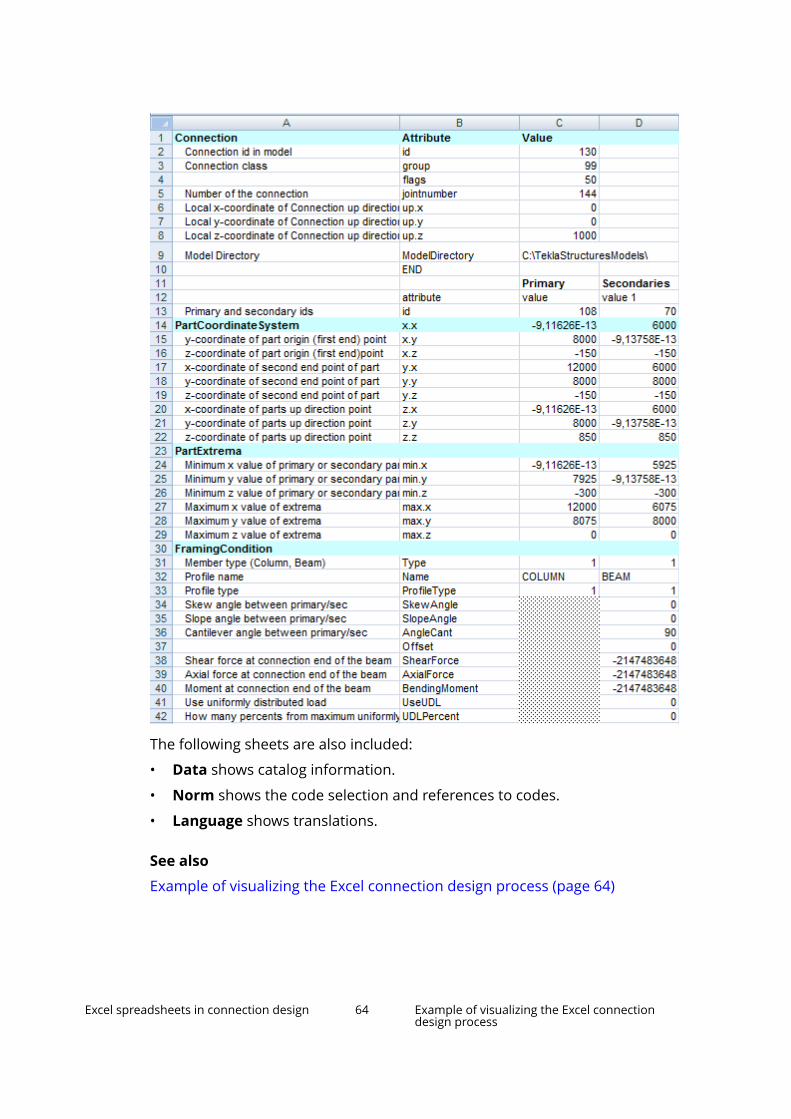
The following sheets are also included:
• Data shows catalog information.
• Norm shows the code selection and references to codes.
• Language shows translations.
See also
Example of visualizing the Excel connection design process (page 64)
Excel spreadsheets in connection design 64 Example of visualizing the Excel connectiondesign process

3.3 Example of visualizing the Excel connection designprocessYou can define in the Excel.vb file how the Excel connection design processis visualized. The Excel.vb file links Tekla Structures with the externalsoftware and defines the Excel spreadsheet file names and the locations.
1. Open the Excel.vb file located in ..\Tekla Structures\<version>\Environments\common\exceldesign.
2. Configure the Excel.vb file as follows:
• Visualizing control - Const DEBUG As Boolean= True• Visualizing using Excel - Const SHOW_EXCEL As Boolean = True• Storing the output - Const STORE_RESULTS As Boolean = True
3. Save the file.
4. Click the Applications & components button in the side pane toopen the Applications & components catalog.
5. Search for Clip angle (141) and double-click it to open the propertiesdialog box.
Excel spreadsheets in connection design 65 Example of visualizing the Excel connectiondesign process

6. On the Design type tab:
a. Select Excel in the External design option.
b. Enter the load values.
7. Click Modify.
Excel spreadsheets in connection design 66 Example of visualizing the Excel connectiondesign process

The Excel design file opens and shows the Inputs sheet.
8. Click OK to continue.
Excel spreadsheets in connection design 67 Example of visualizing the Excel connectiondesign process

The Excel design process now calculates the data that is shown on theComponent sheet, and then opens the Component sheet.
9. Click OK to continue.
The Excel design process now calculates the result output values and thenopens the Outputs sheet. The calculated results values are transferred tothe connection.
Excel spreadsheets in connection design 68 Example of visualizing the Excel connectiondesign process
10. Save the file in the model folder.
11. When you click OK, the design process is completed and the Excel designfile is closed.
See also
Files used in Excel spreadsheet connection design (page 59)
Example of an Excel spreadsheet in connection design (page 61)
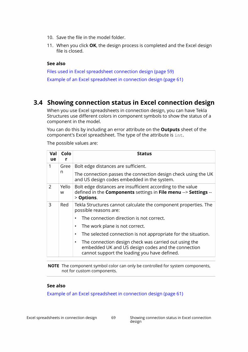
3.4 Showing connection status in Excel connection designWhen you use Excel spreadsheets in connection design, you can have TeklaStructures use different colors in component symbols to show the status of acomponent in the model.
You can do this by including an error attribute on the Outputs sheet of thecomponent's Excel spreadsheet. The type of the attribute is int.
The possible values are:
Value
Color
Status
1 Green
Bolt edge distances are sufficient.
The connection passes the connection design check using the UKand US design codes embedded in the system.
2 Yellow
Bolt edge distances are insufficient according to the valuedefined in the Components settings in File menu --> Settings --> Options.
3 Red Tekla Structures cannot calculate the component properties. Thepossible reasons are:
• The connection direction is not correct.
• The work plane is not correct.
• The selected connection is not appropriate for the situation.
• The connection design check was carried out using theembedded UK and US design codes and the connectioncannot support the loading you have defined.
NOTE The component symbol color can only be controlled for system components,not for custom components.
See also
Example of an Excel spreadsheet in connection design (page 61)
Excel spreadsheets in connection design 69 Showing connection status in Excel connectiondesign

4 Disclaimer
© 2016 Trimble Solutions Corporation and its licensors. All rights reserved.
This Software Manual has been developed for use with the referencedSoftware. Use of the Software, and use of this Software Manual are governedby a License Agreement. Among other provisions, the License Agreement setscertain warranties for the Software and this Manual, disclaims otherwarranties, limits recoverable damages, defines permitted uses of theSoftware, and determines whether you are an authorized user of the Software.All information set forth in this manual is provided with the warranty set forthin the License Agreement. Please refer to the License Agreement for importantobligations and applicable limitations and restrictions on your rights. Trimbledoes not guarantee that the text is free of technical inaccuracies ortypographical errors. Trimble reserves the right to make changes andadditions to this manual due to changes in the software or otherwise.
In addition, this Software Manual is protected by copyright law and byinternational treaties. Unauthorized reproduction, display, modification, ordistribution of this Manual, or any portion of it, may result in severe civil andcriminal penalties, and will be prosecuted to the full extent permitted by law.
Tekla, Tekla Structures, Tekla BIMsight, BIMsight, Tekla Civil, Tedds, Solve,Fastrak and Orion are either registered trademarks or trademarks of TrimbleSolutions Corporation in the European Union, the United States, and/or othercountries. More about Trimble Solutions trademarks: http://www.tekla.com/tekla-trademarks. Trimble is a registered trademark or trademark of TrimbleNavigation Limited in the European Union, in the United States and/or othercountries. More about Trimble trademarks: http://www.trimble.com/trademarks.aspx. Other product and company names mentioned in thisManual are or may be trademarks of their respective owners. By referring to athird-party product or brand, Trimble does not intend to suggest an affiliationwith or endorsement by such third party and disclaims any such affiliation orendorsement, except where otherwise expressly stated.
Portions of this software:
D-Cubed 2D DCM © 2010 Siemens Industry Software Limited. All rightsreserved.
Disclaimer 70 Showing connection status in Excel connectiondesign

EPM toolkit © 1995-2004 EPM Technology a.s., Oslo, Norway. All rightsreserved.
Open CASCADE Technology © 2001-2014 Open CASCADE SA. All rightsreserved.
FLY SDK - CAD SDK © 2012 VisualIntegrity™. All rights reserved.
Teigha © 2003-2014 Open Design Alliance. All rights reserved.
PolyBoolean C++ Library © 2001-2012 Complex A5 Co. Ltd. All rights reserved.
FlexNet Copyright © 2014 Flexera Software LLC. All Rights Reserved.
This product contains proprietary and confidential technology, informationand creative works owned by Flexera Software LLC and its licensors, if any. Anyuse, copying, publication, distribution, display, modification, or transmission ofsuch technology in whole or in part in any form or by any means without theprior express written permission of Flexera Software LLC is strictly prohibited.Except where expressly provided by Flexera Software LLC in writing,possession of this technology shall not be construed to confer any license orrights under any Flexera Software LLC intellectual property rights, whether byestoppel, implication, or otherwise.
To see the third party licenses, go to Tekla Structures, click File menu --> Help--> About Tekla Structures and then click the 3rd party licenses option.
The elements of the software described in this Manual are protected byseveral patents and possibly pending patent applications in the United Statesand/or other countries. For more information go to page http://www.tekla.com/tekla-patents.
Disclaimer 71 Showing connection status in Excel connectiondesign

Disclaimer 72 Showing connection status in Excel connectiondesign

Index
Excelconnection design...................................64
Aangle box
properties.................................................32
Bbeam cut
properties.................................................26bolt diameter.................................................49bolt dimension properties........................... 57bolt properties...............................................51bolts
properties.................................................19
Ccomponent analysis properties...................41connection analysis properties................... 41connection design
Excel.......................................... 59,61,64,69connection part properties..........................51connection properties.................................... 3
bolt dimensions.......................................57diagonal....................................................55gussets......................................................52profiles......................................................57
connection weld properties.........................37connections......................................................3
Ddefault connection properties..... 44,47,49,51default connection settings...............44,49,51design check.................................................. 39design tab...................................................... 39
detail analysis properties............................. 41diagonal connection properties.................. 55doubler plates
properties.................................................29
EExcel
connection design.........................59,61,69
Ggeneral tab.....................................................38gusset properties.......................................... 52
Hhaunch
properties...................................................8
Jjoints. def....................................................... 44joints.def......................... 44,47,49,51,52,55,57
Nnotch
properties........................................... 10,15
Pproperties
connections................................................3
73

Ssteel connection properties....5,8,10,15,19,26,29,32,37,38,39steel connections............................................ 3
parts............................................................ 3steel connections properties......................... 3steel detail properties...................................38stiffeners
properties...................................................5
UUDL................................................................. 39uniform distributed load..............................39up direction....................................................38
Wwelds...............................................................37
74