Embed Size (px)
Citation preview

Tekelec EAGLE® 5
Feature Manual - IS41 GSM Migration910-6269-001 Revision A
January 2012
Copyright 2012 Tekelec. All Rights Reserved. Printed in USA.Legal Information can be accessed from the Main Menu of the optical disc or on the
Tekelec Customer Support web site in the Legal Information folder of the Product Support tab.

Table of Contents
Chapter 1: Introduction.......................................................................6Overview....................................................................................................................................7Scope and Audience.................................................................................................................7Manual Organization................................................................................................................7Documentation Admonishments............................................................................................8Customer Care Center..............................................................................................................8Emergency Response..............................................................................................................10Related Publications...............................................................................................................11Documentation Availability, Packaging, and Updates.....................................................11Locate Product Documentation on the Customer Support Site.......................................12
Chapter 2: Feature Description........................................................13Introduction.............................................................................................................................14
IS412GSM Migration Changes..................................................................................18IGM Protocol............................................................................................................................18
LOCREQ Query Response.........................................................................................31MTP Routed SCCP Traffic.........................................................................................36IGM SRI-SM Relay to Default IS41 SMSC...............................................................38
General Numbering Requirements......................................................................................39Hardware Requirements........................................................................................................40MPS/EPAP Platform..............................................................................................................40
EPAP/PDBA Overview.............................................................................................42Subscriber Data Provisioning....................................................................................43EPAP (EAGLE Provisioning Application Processor)............................................45Service Module Cards................................................................................................46Network Connections.................................................................................................49
Chapter 3: Commands........................................................................54Introduction.............................................................................................................................55EAGLE 5 ISS GSM System Options Commands................................................................55EAGLE 5 ISS GSM SMS Options Commands.....................................................................58EAGLE 5 ISS IS41 Options Commands...............................................................................58EAGLE 5 ISS Service Selector Commands..........................................................................62EAGLE 5 ISS Feature Control Commands..........................................................................65
ii910-6269-001 Revision A, January 2012

EAGLE 5 ISS SCCP Service Commands..............................................................................66
Chapter 4: Feature Configuration....................................................69Introduction.............................................................................................................................70EPAP Entity Provisioning......................................................................................................71Prerequisites.............................................................................................................................71EAGLE 5 ISS HLR Destinations Configuration..................................................................72IGM Feature Activation Procedure......................................................................................78The 1100 TPS/DSM for ITU NP Feature.............................................................................81
Enable the 1100 TPS/DSM for ITU NP Feature......................................................84Turn On the 1100 TPS/DSM for ITU NP Feature..................................................85Turn Off the 1100 TPS/DSM for ITU NP Feature..................................................86
Activating the E5-SM4G Throughput Capacity Feature...................................................86Adding a Service Module Card............................................................................................90LOCREQ Query Response Activation Procedure..............................................................97Service Portability Activation Procedure..........................................................................100MTP Routed Messages for SCCP Applications Activation Procedure.........................101
Chapter 5: Measurements................................................................103IGM Measurements..............................................................................................................104
Chapter 6: Maintenance...................................................................107IGM Related Alarms.............................................................................................................108IGM UIMs...............................................................................................................................110Maintenance Commands.....................................................................................................112
rept-stat-sccp..............................................................................................................114EAGLE 5 ISS Debug Commands........................................................................................114EPAP Status and Alarm Reporting.....................................................................................114
DSM Status Requests................................................................................................115IGM System Status Reports.................................................................................................116
Glossary..................................................................................................................118
iii910-6269-001 Revision A, January 2012

List of FiguresFigure 1: LOCREQ Query Reponse RN Determination................................................................33Figure 2: MPS/EPAP Platform Architecture..................................................................................41Figure 3: Subscriber Data Provisioning Architecture (High Level).............................................44Figure 4: Database Administrative Architecture............................................................................46Figure 5: Customer Provisioning Network.....................................................................................50Figure 6: EPAP Sync Network..........................................................................................................51Figure 7: DSM Networks....................................................................................................................52Figure 8: Dial-Up PPP Network........................................................................................................53
iv910-6269-001 Revision A, January 2012

List of TablesTable 1: Admonishments.....................................................................................................................8Table 2: IGM Customer Message Processing..................................................................................20Table 3: IGM and G-Port Customer Message Processing.............................................................22Table 4: IGM and A-Port Message Processing................................................................................23Table 5: IGM, A-Port, and G-Port Customer Message Processing..............................................24Table 6: DigitAction Applications....................................................................................................26Table 7: MNP SCCP Service Re-Route Capability Summary.......................................................30Table 8: Service Portability vs Number Portability by Destination Subscriber Type...............35Table 9: Subscriber Portability Type.................................................................................................38Table 10: Changes in SRI-SM Relayed to Default IS41 SMSC .....................................................39Table 11: Service Module Card Provisioning and Reload Settings..............................................48Table 12: EPAP IP Addresses in the DSM Network......................................................................52Table 13: chg-gsmopts Parameters...................................................................................................55Table 14: chg-gsmsmsopts Parameters............................................................................................58Table 15: chg-is41opts Parameters - Class = DATABASE.............................................................59Table 16: ent-srvsel Parameters.........................................................................................................62Table 17: chg-srvsel Parameters........................................................................................................63Table 18: dlt-srvsel Parameters.........................................................................................................64Table 19: rtrv-srvsel Parameters........................................................................................................65Table 20: chg-sccp-serv Parameters..................................................................................................66Table 21: dlt-sccp-serv Parameters...................................................................................................67Table 22: Feature Activation Summary............................................................................................70Table 23: System Prerequisites..........................................................................................................82Table 24: Feature Prerequisites..........................................................................................................83Table 25: Maximum E5-SM4G, E5-SM8G-B, and System TPS Capacity.....................................86Table 26: System Prerequisites..........................................................................................................88Table 27: E5-SM4G Throughput Capacity Feature Prerequisite..................................................89Table 28: Service Module Card Locations.......................................................................................91Table 29: System Prerequisites for Adding a Service Module Card............................................91Table 30: Prerequisite for Adding an E5-SM4G Service Module Card.......................................92Table 31: Prerequisites for Adding an E5-SM8G-B Service Module Card..................................92Table 32: Pegs for Per System IGM Measurements......................................................................104Table 33: Pegs for Per SSP IGM Measurements............................................................................105Table 34: Pegs for Per System and Per SSP IGM Measurements...............................................106Table 35: IGM Related UAMs..........................................................................................................108Table 36: IGM Related UIMs...........................................................................................................110Table 37: Maintenance Commands.................................................................................................112
v910-6269-001 Revision A, January 2012

Chapter
1Introduction
This chapter provides a brief description of theIS41GSM Migration (IGM) feature of the EAGLE 5
Topics:
• Overview.....7 Integrated Signaling System. The chapter also• Scope and Audience.....7 includes the scope, audience, and organization of
the manual; how to find related publications; andhow to contact Tekelec for assistance.
• Manual Organization.....7• Documentation Admonishments.....8• Customer Care Center.....8• Emergency Response.....10• Related Publications.....11• Documentation Availability, Packaging, and
Updates.....11• Locate Product Documentation on the Customer
Support Site.....12
6910-6269-001 Revision A, January 2012

Overview
This manual provides feature descriptions, commands, maintenance, measurements, and configurationdetails associated with the IS41 GSM Migration (IGM) feature deployed on an EAGLE 5 IntegratedSignaling System (ISS) that is also performing the STP function. The IGM feature applies to ITU andANSI networks.
The IGM feature provides the mobile wireless service provider a way to migrate subscribers fromIS-41 to GSM and GSM to IS-41. After the subscriber is marked as migrated, the GSM handset is fullyfunctional, and the migrated subscriber has the option whether to continue to receive calls on the IS-41or GSM handset.
Number lengths vary between countries and may vary within a country. As a result, the databasestructure supports numbers of varying length in a flexible way without requiring softwaremodifications. A maximum number length of 15 digits for ported numbers is supported.
IGM is an optional feature on the EAGLE 5 ISS, and can be enabled and turned on, but not off, via afeature access key. Note that the IGM feature requires the Global Title Translation (GTT) feature andthat IGM and North American LNP (Local Number Portability) are mutually exclusive on an EAGLE5 ISS node.
Scope and Audience
This manual is intended for anyone responsible for installing, maintaining, and using the IGM featurein the EAGLE 5 ISS. Users of this manual and the others in the EAGLE 5 ISS family of documents musthave a working knowledge of telecommunications and network installations.
Manual Organization
This document is organized into the following chapters:
• Introduction contains general information about the IGM documentation, the organization of thismanual, and how to request technical assistance.
• Feature Description provides a functional description of the IGM feature, including networkperspectives, assumptions and limitations, database overview, Service Module card provisioningand reloading, and IGM user interface.
• Commands describes the commands that support the IGM feature and explanations of appropriatecommand usage.
• Feature Configuration describes how to activate the IGM feature.• Measurements describes the measurements available for IGM.• Maintenance describes IGM maintenance information, including EPAP status and alarms, hardware
verification messages, system status reports and commands, code and application data loading,and alarms.
7910-6269-001 Revision A, January 2012
IntroductionFeature Manual - IS41 GSM Migration

Documentation Admonishments
Admonishments are icons and text throughout this manual that alert the reader to assure personalsafety, to minimize possible service interruptions, and to warn of the potential for equipment damage.
Table 1: Admonishments
DANGER:
(This icon and text indicate the possibility of personal injury.)
WARNING:
(This icon and text indicate the possibility of equipment damage.)
CAUTION:
(This icon and text indicate the possibility of service interruption.)
Customer Care Center
The Tekelec Customer Care Center is your initial point of contact for all product support needs. Arepresentative takes your call or email, creates a Customer Service Request (CSR) and directs yourrequests to the Tekelec Technical Assistance Center (TAC). Each CSR includes an individual trackingnumber. Together with TAC Engineers, the representative will help you resolve your request.
The Customer Care Center is available 24 hours a day, 7 days a week, 365 days a year, and is linkedto TAC Engineers around the globe.
Tekelec TAC Engineers are available to provide solutions to your technical questions and issues 7days a week, 24 hours a day. After a CSR is issued, the TAC Engineer determines the classification ofthe trouble. If a critical problem exists, emergency procedures are initiated. If the problem is not critical,normal support procedures apply. A primary Technical Engineer is assigned to work on the CSR andprovide a solution to the problem. The CSR is closed when the problem is resolved.
Tekelec Technical Assistance Centers are located around the globe in the following locations:
Tekelec - Global
Email (All Regions): [email protected]
• USA and Canada
Phone:
1-888-FOR-TKLC or 1-888-367-8552 (toll-free, within continental USA and Canada)
1-919-460-2150 (outside continental USA and Canada)
8910-6269-001 Revision A, January 2012
IntroductionFeature Manual - IS41 GSM Migration

TAC Regional Support Office Hours:
8:00 a.m. through 5:00 p.m. (GMT minus 5 hours), Monday through Friday, excluding holidays• Caribbean and Latin America (CALA)
Phone:
USA access code +1-800-658-5454, then 1-888-FOR-TKLC or 1-888-367-8552 (toll-free)
TAC Regional Support Office Hours (except Brazil):
10:00 a.m. through 7:00 p.m. (GMT minus 6 hours), Monday through Friday, excluding holidays
• Argentina
Phone:
0-800-555-5246 (toll-free)• Brazil
Phone:
0-800-891-4341 (toll-free)
TAC Regional Support Office Hours:
8:30 a.m. through 6:30 p.m. (GMT minus 3 hours), Monday through Friday, excluding holidays• Chile
Phone:
1230-020-555-5468• Colombia
Phone:
01-800-912-0537• Dominican Republic
Phone:
1-888-367-8552• Mexico
Phone:
001-888-367-8552• Peru
Phone:
0800-53-087• Puerto Rico
Phone:
1-888-367-8552 (1-888-FOR-TKLC)• Venezuela
Phone:
9910-6269-001 Revision A, January 2012
IntroductionFeature Manual - IS41 GSM Migration

0800-176-6497
• Europe, Middle East, and Africa
Regional Office Hours:
8:30 a.m. through 5:00 p.m. (GMT), Monday through Friday, excluding holidays
• Signaling
Phone:
+44 1784 467 804 (within UK)• Software Solutions
Phone:
+33 3 89 33 54 00
• Asia
• India
Phone:
+91 124 436 8552 or +91 124 436 8553
TAC Regional Support Office Hours:
10:00 a.m. through 7:00 p.m. (GMT plus 5 1/2 hours), Monday through Saturday, excludingholidays
• Singapore
Phone:
+65 6796 2288
TAC Regional Support Office Hours:
9:00 a.m. through 6:00 p.m. (GMT plus 8 hours), Monday through Friday, excluding holidays
Emergency Response
In the event of a critical service situation, emergency response is offered by the Tekelec Customer CareCenter 24 hours a day, 7 days a week. The emergency response provides immediate coverage, automaticescalation, and other features to ensure that the critical situation is resolved as rapidly as possible.
A critical situation is defined as a problem with the installed equipment that severely affects service,traffic, or maintenance capabilities, and requires immediate corrective action. Critical situations affectservice and/or system operation resulting in one or several of these situations:
• A total system failure that results in loss of all transaction processing capability• Significant reduction in system capacity or traffic handling capability• Loss of the system’s ability to perform automatic system reconfiguration• Inability to restart a processor or the system
10910-6269-001 Revision A, January 2012
IntroductionFeature Manual - IS41 GSM Migration

• Corruption of system databases that requires service affecting corrective actions• Loss of access for maintenance or recovery operations• Loss of the system ability to provide any required critical or major trouble notification
Any other problem severely affecting service, capacity/traffic, billing, and maintenance capabilitiesmay be defined as critical by prior discussion and agreement with the Tekelec Customer Care Center.
Related Publications
For information about additional publications that are related to this document, refer to the RelatedPublications document. The Related Publications document is published as a part of the ReleaseDocumentation and is also published as a separate document on the Tekelec Customer Support Site.
Documentation Availability, Packaging, and Updates
Tekelec provides documentation with each system and in accordance with contractual agreements.For General Availability (GA) releases, Tekelec publishes a complete EAGLE 5 ISS documentation set.For Limited Availability (LA) releases, Tekelec may publish a documentation subset tailored to specificfeature content or hardware requirements. Documentation Bulletins announce a new or updatedrelease.
The Tekelec EAGLE 5 ISS documentation set is released on an optical disc. This format allows for easysearches through all parts of the documentation set.
The electronic file of each manual is also available from the Tekelec Customer Support site. This siteallows for 24-hour access to the most up-to-date documentation, including the latest versions of FeatureNotices.
Printed documentation is available for GA releases on request only and with a lead time of six weeks.The printed documentation set includes pocket guides for commands and alarms. Pocket guides mayalso be ordered separately. Exceptions to printed documentation are:
• Hardware or Installation manuals are printed without the linked attachments found in the electronicversion of the manuals.
• The Release Notice is available only on the Customer Support site.
Note: Customers may print a reasonable number of each manual for their own use.
Documentation is updated when significant changes are made that affect system operation. Updatesresulting from Severity 1 and 2 Problem Reports (PRs) are made to existing manuals. Other changesare included in the documentation for the next scheduled release. Updates are made by re-issuing anelectronic file to the customer support site. Customers with printed documentation should contacttheir Sales Representative for an addendum. Occasionally, changes are communicated first with aDocumentation Bulletin to provide customers with an advanced notice of the issue until officiallyreleased in the documentation. Documentation Bulletins are posted on the Customer Support site andcan be viewed per product and release.
11910-6269-001 Revision A, January 2012
IntroductionFeature Manual - IS41 GSM Migration

Locate Product Documentation on the Customer Support Site
Access to Tekelec's Customer Support site is restricted to current Tekelec customers only. This sectiondescribes how to log into the Tekelec Customer Support site and locate a document. Viewing thedocument requires Adobe Acrobat Reader, which can be downloaded at www.adobe.com.
1. Log into the Tekelec Customer Support site.
Note: If you have not registered for this new site, click the Register Here link. Have your customernumber available. The response time for registration requests is 24 to 48 hours.
2. Click the Product Support tab.3. Use the Search field to locate a document by its part number, release number, document name, or
document type. The Search field accepts both full and partial entries.4. Click a subject folder to browse through a list of related files.5. To download a file to your location, right-click the file name and select Save Target As.
12910-6269-001 Revision A, January 2012
IntroductionFeature Manual - IS41 GSM Migration

Chapter
2Feature Description
This chapter describes the IS41 GSM Migration(IGM) feature.
Topics:
• Introduction.....14• IGM Protocol.....18• General Numbering Requirements.....39• Hardware Requirements.....40• MPS/EPAP Platform.....40
13910-6269-001 Revision A, January 2012

Introduction
The IS41 GSM Migration (IGM) feature supports call termination for customers to migrate from IS-41to GSM and GSM to IS-41 wireless technology. This is referred to as Portability Type = 5 (PT = 5). Thisfeature provides the mobile wireless service provider a way to migrate subscribers from IS-41 to GSMand GSM to IS-41. Once the subscriber is marked as migrated, the GSM handset is fully functional,and the migrated subscriber has the option whether to continue to receive calls on the IS-41 or GSMhandset.
IGM provides the ability for subscribers to change service providers while retaining their MobileDialed Number (MDN). IGM uses the EPAP Real Time Database (RTDB) to maintain subscriberportability and migration information. Subscriber information in the EPAP RTDB is keyed by MobileMDNs for ANSI-41 subscribers and Mobile Station International ISDN Number (MSISDNs) for GSMsubscribers.
IGM treats only those DN entries assigned with SP/PT= 5, No NE/PT=5, or assigned with RN/PT=0 as migrated subscribers. Any other types of NE/PT assignments are not considered as migrated orported subscribers.
Two types of subscriber entries, migrated and non-migrated subscribers, are supported. For migratedsubscribers, the subscriber entries are entered with No NE/PT=5, SP/PT=5, and RN/PT=0. All otherentries are non-migrated subscribers. IGM also supports DN block entries.
The ETSI standards are defined so that GSM carriers can choose to implement either Signaling RelayFunction (SRF)-based (using MAP protocol) MNP or IN-based (using INAP protocol) MNP. IGMsupports only the SRF-based solution for MNP. (INAP-based MNP processing is similar to wirelinenetworks; this function is supported by the INP feature.)
Message Interception
SRF-based MNP processing involves the “intercepting” of existing MAP messages to check for portednumbers. For call-related messages, IGM acts as an “NP HLR” in the case where the number has beenexported, by responding to the switch with an SRI, SRI-SM, LOCREQ, and SMSREQ ack messages.For non-migrated calls, IGM performs message relay.
Routing Options
The ETSI standards for SRF-based MNP define two routing options, direct routing and indirect routing.IGM supports both options:
• With direct routing, the network where the call is originated is responsible for determining whetherthe called party has ported and routing the call to the new subscription network.
• With indirect routing, this is the responsibility of the network that originally owned the number.
Number Lengths
Number lengths vary among countries and may even vary within a country. As a result, IGM supportsnumbers of varying length in a flexible way without necessitating software modifications. A maximumnumber length of 15 digits for ported numbers is supported.
14910-6269-001 Revision A, January 2012
Feature DescriptionFeature Manual - IS41 GSM Migration

Supported Messages
IGM uses the EPAP RTDB to derive the portability status of a subscriber.
IGM supports LOCREQ messages as well as SMSREQ messages, if the option is selected, for numberportability handling. LOCREQ messages generate a LOCREQ response if the mobile dialed number(MDN) is migrated and relays the LOCREQ if the MDN is not ported (non-ported or ported in arehandled the same way).
SMSREQ messages generate a SMSREQ NAK if access is denied and relays the SMSREQ if SMSREQBYPASS is set to false. SRI generates an ACK if the MSISDN is migrated, and relays the message ifthe dialed number is not migrated. SRI-SM generates an ACK if the dialed number is migrated, andrelays the message if it is not.
MTP Routed SCCP Traffic
When the MTP Msgs for SCCP Apps feature is turned on, all MTP routed UDT/non-segmented XUDTSCCP messages are routed to Service Module cards. When the MTP Routed GWS Stop Action featureis turned on, messages are filtered based on the provisioned Gateway Screening rules on a per linksetbasis. The MTP Routed GWS Stop Action feature forwards only UDT, UDTS, XUDT and XUDTS SCCPmessages to the Service Module cards for processing.The Service Module cards then perform SCCPdecode and verification on the MTP routed messages.
MNP Circular Route Prevention
The MNP Circular Route Prevention (MNPCRP) feature detects circular routing caused by incorrectinformation in one or more of the network number portability databases. For example, a subscribermay have ported from network A to network B. Network A has the correct routing information,indicating the subscriber now belongs to network B. However, network B may have incorrect routinginformation, indicating that the subscriber still belongs to network A. In this case, network A routesthe call to network B, based on its portability data, but network B routes the call back to network A,based on its incorrect data. The result is a circular route. The MNPCRP feature provides logic to preventthe circular routing from occurring.
MNP Circular Route Prevention is not valid when only IS41 GSM Migration (IGM) is turned on.ANSI-41 Mobile Number Portability (A-Port) or GSM Mobile Number Portability (G-Port) must beturned on for MNP Circular Route Prevention processing to be valid. Circular route prevention foronly ITU MAP messages is supported when only IGM is turned on.
The MNP Circular Route Prevention feature (MNPCRP) allows Circular Route Prevention based onthe Translation Type (TT) of the SCCP CdPA to be performed for SRI messages when a Home RoutingNumber (HomeRN) is not present. For the Circular Route Prevention on Translation Type processingto be performed, the crptt parameter of the chg-gsmopts command must be set to a value between0 and 255. If the crptt parameter of the chg-gsmopts command is set to the default value of none,then no Circular Route Prevention on Translation Type processing is performed. The MNP CircularRoute Prevention feature cannot be turned off if the crptt parameter is provisioned to any valueother than none. If a message is processed for Circular Route Prevention based on HomeRN, thenCircular Route Prevention on Translation Type processing does not occur.
SRI messages must meet these criteria to be eligible for Circular Route Prevention on Translation Type:
• The message is selected for G-Port or IS41 GSM Migration processing.• The message is not identified as G-Port SRI Query for Prepaid.• The message is not MTP-routed. (The CdPA is Route-on-GT.)
15910-6269-001 Revision A, January 2012
Feature DescriptionFeature Manual - IS41 GSM Migration

• The translation type of the SCCP CdPA matches the provisioned translation type (crptt).• The ITU TCAP Package type is ITU Begin.• The OpCode is an SRI (hexadecimal 16).• The Optimal Routing Interrogation Parameter (Tag = 0x04) is not present.• The MSISDN is not assigned to the subscriber's network provider.
DigitAction Expansion
The DigitAction Expansion feature provides more flexibility to formulate the SCCP Called PartyAddress (SCCP) Global Title Address (GTA) field of the MAP messages relayed by IGM.
DigitAction Expansion is provisioned via the PDBI Enter Network Entity or Update Network Entitycommands. DigitAction Expansion can also be modified via the Add an NE and Update an NE GUIscreens.
Digit Action DELCCPREFIX
The Digit Action to delete country code if present and prefix database entity feature allows theDELCCPREFIX Digit Action to be applied to the Called Party Global Title Address (CdPA GTA) whenthe GTA has a National format, as well as when the GTA has an International format. TheDELCCPREFIX option in the SCCPOPTS table specifies how the DELCCPREFIX digit action is appliedto a Called Party Global Title Address (CdPA GTA).
• When the SCCPOPTS:DELCCPREFIX option is set to PFXWCC, the DELCCPREFIX digit action isapplied to the CdPA GTA only when the address has a International format. The Country Code isdeleted and the GTA is prefixed with the Entity ID.
• When the SCCPOPTS:DELCCPREFIX option is set to PFX4ALL, the DELCCPREFIX digit action isapplied to the CdPA GTA in all cases. For an International format, the Country Code is deletedand the GTA is prefixed with the Entity ID. For a National format, the GTA is prefixed with theEntity ID.
The chg-sccpopts command is used to specify the delccprefix parameter value to configure theDELCCPREFIX Digit Action functionality.
MNP SCCP Service Re-Route
The MNP SCCP Service Re-Route feature is used when the IGM subscriber database is incoherentwith MPS data and the GTT data is valid. The MNP SCCP Service Re-Route feature provides thecapability to re-route the traffic from the EAGLE 5 ISS to other IGM subscriber database nodes andinform the originating nodes to re-route the IGM service related traffic to other IGM service nodes.
The MNP SCCP Service Re-Route feature is designed to handle and control re-routing of IGM trafficfrom an affected node to alternate nodes within an operators network. This feature is an optionalfeature and does not affect the normal IGM function. This feature also provides the option to markIGM offline to perform a controlled re-routing during this state.
ROP Support
The IS41 GSM Migration (IGM) feature allows Small Geographic Areas (CNLs) to be grouped intoLarge Geographic Areas (ROPs). This grouping simplifies the routing and allows a call to be deliveredas close to the interconnection destination as possible. ROP information is stored in the generic routing
16910-6269-001 Revision A, January 2012
Feature DescriptionFeature Manual - IS41 GSM Migration

number (GRN) field. Both CNL and ROP information can be provisioned for a single subscriber entry;however, only one of the CNL or ROP fields can be selected for the outgoing message
The G-Port, G-Port SRI Query for Prepaid, GSM MAP SRI Redirect, AINPQ, INP, and ATINP featuresalso support ROP.
Include Optional CUG Parameter in SRI Ack Messages
The Include Optional CUG Parameter in SRI Ack Messages functionality allows an existing ClosedUser Group-CheckInfo (CUG-CheckInfo) parameter in an incoming SRI message to be included in theoutgoing SRI Ack message.
The Include Optional CUG Parameter in SRI Ack Messages functionality is controlled by the encodecugoption of the chg-gsmopts command off and on parameters. The encodecug option of thechg-gsmopts off/on parameter can be changed only if the G-Port or IGM feature is enabled.
The CUG-CheckInfo parameter in an incoming SRI message is copied in the original sequence to theoutgoing SRI Ack message when these conditions are met:
• The encodecug option of the chg-gsmopts command is set to on.• The CUG-CheckInfo parameter is present in an incoming SRI message.• The CUG-CheckInfo parameter in an incoming SRI message is encoded in definite length format
that is less than or equal to 30 bytes.
If the three conditions described above are met, the original CUG-CheckInfo sequence from theincoming SRI message is copied into the SRI Ack message. If encoded in the SRI Ack message, theCUG-CheckInfo parameter is located after the MSRN (Tag = 0x04) and before the MSISDN (Tag =0x8C) or NPS parameter (Tag = 0x8D), if either MSISDN or NPS parameter is present. TheCUG-CheckInfo parameter in an SRI Ack message uses Tag = 0xA3.
If the CUG-CheckInfo parameter is greater than 30 bytes and all other conditions for encoding aremet, then only the CUG-Interlock and CUG-OutgoingAccess parameters are copied from an incomingSIR message to the outgoing SRI Ack message. The ExtensionContainer is omitted.
When the encodecug option is set to off, the CUG-CheckInfo parameter is not encoded in the SRIAck message.
If the encodecug option is set to on but the CUG-CheckInfo parameter in an incoming SRI messageuses an indefinite length format, the CUG-CheckInfo parameter is not encoded in the SRI Ack message.
Route SRI_SM and ReportSMSDeliveryStatus for Non-local or Ported-out Subscribers using GTT
The Route SRI_SM and ReportSMSDeliveryStatus for Non-local or Ported-out Subscribers using GTTfunctionality modifies SRI_SM and ReportSMSDeliveryStatus messages to allow routing of the messageto an alternate network using Global Title Translation (GTT). This functionality allows processing tooccur when the Directory Number (DN) in the database is associated with both the Service Point (SP)and Generic Routing Number (GRN) network elements and the GRN is not present in the EAGLE 5ISS HomeRN table, or when the subscriber is ported out and associated with the Routing Number(RN).
The message is altered by changing the SCCP Called Party Address (CdPA) to the Country Code (CC)+ GRN + DN or to CC + RN + DN. This alteration allows GTT to redirect the query to an alternatenetwork. If a CC is not located in the DN, then the SCCP CdPA is converted to a GRN + DN or RN +DN format.
17910-6269-001 Revision A, January 2012
Feature DescriptionFeature Manual - IS41 GSM Migration

This conversion is performed only on ITU TCAP Begin MSUs with Op Code of SRI_SM orReportSMSDeliveryStatus delivered to the GPort or MNP service selector for processing. If the MT-BasedGSM SMS NP or the IS41 GSM Migration (IGM) feature generates a response for the SRI_SM message,then this functionality is not applicable.
The Route SRI_SM and ReportSMSDeliveryStatus for Non-local or Ported-out subscribers using GTTfunctionality is controlled by the srismgttrtg option of the chg-gsmopts command off and onparameters. The srismgttrtg option of the chg-gsmopts off/on parameter can be changed onlyif the G-Port or IGM feature is enabled.
Option to Suppress NumberPortabilityStatusIndicator in SRI Ack
The Option to Suppress NumberPortabilityStatusIndicator in SRI Ack functionality allows the NumberPortability Status Indicator (NPSI) to be omitted from all SRI Ack messages.
The Option to Suppress NumberPortabilityStatusIndicator in SRI Ack functionality is controlled bythe encodenps option of the chg-gsmopts command off and on parameters. The encodenpsoption of the chg-gsmopts off/on parameter can be changed only if the G-Port or IGM feature isenabled.
The NumberPortabilityStatusIndicator parameter is encoded in an SRI Ack message when theseconditions are met:
• The encodenps option of the chg-gsmopts command is set to on.• SRI is considered MAP Phase 2+.• DN Portability Type is 0, 1, 2, or 36. (Portability Type = 36 is encoded as Portability Type = 0.)
Note: MAP Phase is set based on either data in the dialog portion or GSMOPTS:DEFMAPVR if thedialog portion does identify.
The NumberPortabilityStatusIndicator parameter is not encoded in any SRI Ack message if theencodenps option of the chg-gsmopts command is set to off.
IS412GSM Migration Changes
For systems that are upgraded to the IGM feature, the upgrade process sets an SCCP option to on ifthe G-Port feature is turned on and the IS412GSM prefix is defined. If the G-Port feature is turned onand the IS412GSM prefix is not defined, the upgrade process sets the SCCP option to off. The defaultsetting for new systems is off (disabled).
The EAGLE 5 ISS populates a new GSM2IS41 prefix following the same mechanism that is used forthe existing IS412GSM prefix. The EAGLE 5 ISS returns a GSM2IS41 prefix in the SRI Ack message ifa received SRI message is destined for a non-migrated IS41 or GSM migrated IS41 subscriber (a dataentry is found with RN and PT=0).
IGM Protocol
IGM provides the following main functions:
18910-6269-001 Revision A, January 2012
Feature DescriptionFeature Manual - IS41 GSM Migration

Message Discrimination
Because IGM provides translation of migrated and non-migrated numbers, it provides a method toidentify which messages need migration handling versus GTT. This task of identification is providedvia a service selector table where the user defines the service for a combination of selectors.
Operation Code Discrimination
IGM handles ANSI Loc_Req, SMSREQ, GSM SRI, and SRI_SM differently than other ANSI/GSMoperation codes. The Portability type field is only considered for these operation codes. Message relayis performed for all other operation codes based on IGM Translation data.
Number Conditioning
The RTDB stores International MSISDN only. IGM provides the capability to condition incomingnumbers to be international MSISDN (Insert CC or/and NDC) for the database look up. IGM removesthe GSM prefix from GSM SRI messages and then conditions the non-international numbers tointernational numbers, if needed, before performing any database lookup.
IS412GSM
IGM generates a Loc_Req Return Result Response, when the MDN in the Loc_Req is a Migrated withone handset subscriber. When formulating a Loc_Req response, IGM uses the IS412GSM prefix inGSMOPTS to build the Routing Digits. If the IS412GSM prefix is not provisioned, IGM issues UIM1130 IS412GSM not provisioned and falls through to GTT.
GSM2IS41
The GSM2IS41 prefix is used in the SRI Ack message if the message received is SRI and DN lookuphas RN and PT = 0 assigned. If MIGRPFX = MULTPLE, then the RN from the RTDB is used as theprefix in the SRI Ack message. If MIGRPFX = SINGLE and GSM2IS41 prefix is NONE, then the SRIAck message issues UIM 1341 SRI rcvd GSM2is41 prefix not provisioned and the messagefalls through to GTT.
Database Lookup
IGM performs the RTDB database lookup using the international MSISDN.
The individual number database is searched first:
• If the number is not found, the number range database is searched.• If a match is not found in the individual and range-based database, the GTT is performed on the
message.
In the event of the MSISDN numbers in the RTDB database being odd and CDPA GTI of the incomingmessage being ‘2’, and the last digit of the number is 'zero':
• IGM first performs database lookup one time using the even number.• If no match is found, IGM again performs the database lookup, using the odd number (without
last digit).
Since a DN may be the target of the A-Port, G-Port, or IGM message processing in a hybrid network(where an operator owns both GSM and IS41 network), message processing call disposition is based
19910-6269-001 Revision A, January 2012
Feature DescriptionFeature Manual - IS41 GSM Migration

on what applications are in service. Table 2: IGM Customer Message Processing through Table 5: IGM,A-Port, and G-Port Customer Message Processing show call dispositions for the following configurations:
• IGM Only (Table 2: IGM Customer Message Processing)• IGM and G-Port (Table 3: IGM and G-Port Customer Message Processing)• IGM and A-Port (Table 4: IGM and A-Port Message Processing)• A-Port, G-Port, and IGM (Table 5: IGM, A-Port, and G-Port Customer Message Processing
The following notations apply to Table 2: IGM Customer Message Processing through Table 5: IGM,A-Port, and G-Port Customer Message Processing.
PT = Portability Type for the DN
Values:
• 0 – Not known to be ported• 1 – Own number ported out• 2 – Foreign number ported to foreign network• 3 – Prepaid 1 (used by PPSMS)• 4 – Prepaid 2 (used by PPSMS)• 5 – Migrated with one handset• 6 – Prepaid 3 (used by PPSMS)
through• 32 – Prepaid 35 (used by PPSMS)• 36 – Not identified to be ported• FF – No status, No Portability Type
NE = Network Entity
PPSMSPT = Prepaid1 through Prepaid 35 used by PPSMS
RN = Routing Number
SP = Signaling Point
SRI = Send Routing Information
SP* : This row refers to DN is assigned with SP, with or without PT. SP**: This row refers to DN isassigned with SP without PT. DN blocks are commonly assigned with SP and without PT.
Table 2: IGM Customer Message Processing
OtherIS41SMSREQLOCREQOther
GSMSRI_SMSRINE/PT
RelayRelayRelayRelayBased onprovisionedoption:
MIGRPFX =single: ACK, useGSM2IS41 prefix
RN and PT= 0
a)SRI_SM_NACK
MIGRPFX =multiple: ACK,RN from RTDB with Return
20910-6269-001 Revision A, January 2012
Feature DescriptionFeature Manual - IS41 GSM Migration

OtherIS41SMSREQLOCREQOther
GSMSRI_SMSRINE/PT
ErrorComponent
b) Relay toconfigureddefault CDMASMSC
GTTGTTGTTGTTGTTGTTRN and PT≠ 0
RelayIfSMSREQBYPASS= true, then Relay;
ReturnResultwithIS412GSMprefix
RelayRelayRelaySP and
PT = 5
else ReturnResultwith SMS AccessDenied Reason =5
RelayRelayRelayRelayRelayRelaySP and
PT ≠ 5
GTTGTTGTTGTTGTTACK (no NE)No NE
and PT = 0
GTTGTTGTTGTTGTTGTTNo NE andPT=1, 2, 36,or No PT
GTTIfSMSREQBYPASS= true, then GTT;
ReturnResultwithIS412GSMprefix
GTTGTTGTTNo NE andPT = 5
else ReturnResultwith SMS AccessDenied Reason =5
GTTGTTGTTGTTGTTGTTNo NE andPT =PPSMSPT
GTTGTTGTTGTTGTTGTTNo DNentry found
21910-6269-001 Revision A, January 2012
Feature DescriptionFeature Manual - IS41 GSM Migration

Table 3: IGM and G-Port Customer Message Processing
OtherIS41SMSREQLOCREQOther
GSMSRI_SMSRINE/PT
RelayRelayRelayRelayBased onprovisionedoption:
MIGRPFX =single: ACK, useGSM2IS41 prefix
RN and PT= 0
a)SRI_SM_NACK
MIGRPFX =multiple: ACK,RN from RTDB with Return
ErrorComponent
b) Relay toconfigureddefault CDMASMSC
GTTGTTGTTRelayRelayACK (RN fromRTDB)
RN and PT≠ 0 or No PT
for PT = 0, 1, 2:Existing EncodeNPS
for PT = 36:maps to 0
RelayIfSMSREQBYPASS= true, then Relay;
ReturnResultwithIS412GSMprefix
RelayRelayRelaySP and
PT = 5
else ReturnResultwith SMS AccessDenied Reason =5
RelayRelayRelayRelayRelayRelaySP and
PT ≠ 5
GTTIfSMSREQBYPASS= true, then GTT;
ReturnResultwithIS412GSMprefix
GTTGTTGTTNo NE andPT = 5
else ReturnResultwith SMS AccessDenied Reason =5
22910-6269-001 Revision A, January 2012
Feature DescriptionFeature Manual - IS41 GSM Migration

OtherIS41SMSREQLOCREQOther
GSMSRI_SMSRINE/PT
GTTGTTGTTGTTGTTACK (no NE)
for PT = 0:Existing EncodeNPS
No NE andPT= 0, 1, 2,36, or No PT
for PT = 36:maps to 0 ifneeded
GTTGTTGTTGTTGTTGTTNo NE andPT =PPSMSPT
GTTGTTGTTGTTGTTGTTNo DNentry found
Table 4: IGM and A-Port Message Processing
OtherIS41SMSREQLOCREQOther
GSMSRI_SMSRINE/PT
RelayRelayRelayRelayBased onprovisionedoption:
MIGRPFX =single: ACK, useGSM2IS41 prefix
RN and PT= 0
a)SRI_SM_NACK
MIGRPFX=multiple: ACK,RN from RTDB with Return
ErrorComponent
b) Relay toconfigureddefault CDMASMSC
RelayRelayReturnResultwith RNfrom RTDB
GTTGTTGTTRN and PT≠0
RelayIfSMSREQBYPASS= true, then Relay;
ReturnResultwithIS412GSMprefix
RelayRelayRelaySP and PT=5
else ReturnResultwith SMS Access
23910-6269-001 Revision A, January 2012
Feature DescriptionFeature Manual - IS41 GSM Migration

OtherIS41SMSREQLOCREQOther
GSMSRI_SMSRINE/PT
Denied Reason =5
RelayRelayRelayRelayRelayRelaySP and PT≠5
GTTIfSMSREQBYPASS= true, then GTT;
ReturnResultwithIS412GSMprefix
GTTGTTGTTNo NE andPT = 5
else ReturnResultwith SMS AccessDenied Reason =5
GTTGTTReturnResult(no NE)
GTTGTTACK (no NE)No NE andPT = 0
GTTGTTReturnResult(no NE)
GTTGTTGTTNo NE and
PT = 1, 2, 36,or No PT
GTTGTTGTTGTTGTTGTTNo NE andPT =PPSMSPT
GTTGTTGTTGTTGTTGTTNo DNentry found
Table 5: IGM, A-Port, and G-Port Customer Message Processing
OtherIS41SMSREQLOCREQOther
GSMSRI_SMSRINE/PT
RelayRelayRelayRelayBased onprovisionedoption:
MIGRPFX =single: ACK, useGSM2IS41 prefix
RN and PT= 0
a)SRI_SM_NACK
MIGRPFX =multiple: ACK,RN from RTDB with Return
ErrorComponent
24910-6269-001 Revision A, January 2012
Feature DescriptionFeature Manual - IS41 GSM Migration

OtherIS41SMSREQLOCREQOther
GSMSRI_SMSRINE/PT
b) Relay toconfigureddefault CDMASMSC
RelayRelayReturnResultwith RNfrom RTDB
RelayRelayACK (RN fromRTDB)
for PT = 0, 1,2:Existing EncodeNPS
RN and PT≠ 0
for PT = 36: mpsto 0
RelayIfSMSREQBYPASS= true, then Relay;
ReturnResultwithIS412GSMprefix
RelayRelayRelaySP and
PT = 5
else ReturnResultwith SMS AccessDenied Reason =5
RelayRelayRelayRelayRelayRelaySP and
PT ≠ 5
GTTIfSMSREQBYPASS= true, then GTT;
ReturnResultwithIS412GSMprefix
GTTGTTGTTNo NE andPT = 5
else ReturnResultwith SMS AccessDenied Reason =5
GTTGTTReturnResult(no NE)
GTTGTTACK (no NE)
for PT = 0:Existing EncodeNPS
No NE andPT = 0 or 36
for PT = 36:maps to 0
GTTGTTReturnResult(no NE)
GTTGTTACK (no NE)No NE andPT = 1, 2 orNo PT
25910-6269-001 Revision A, January 2012
Feature DescriptionFeature Manual - IS41 GSM Migration

OtherIS41SMSREQLOCREQOther
GSMSRI_SMSRINE/PT
GTTGTTGTTGTTGTTGTTNo NE andPT =PPSMSPT
GTTGTTGTTGTTGTTGTTNo DNentry found
Database lookup results in the following:
1. Applying normal routing or2. Relaying the message to the destination as noted in the database or3. Returning an acknowledge message to the originating switch.
Message Relay
The rules for formatting the SCCP CdPA GTA field are based on the value specified in the DigitActionfield. In the case where a received IS41 message is relayed, the EAGLE formulates the SCCP CdPAGTA field of the outgoing message according to DigitAction specified. If DigitAction = none, theEAGLE 5 ISS does not overwrite the SCCP CdPA GTA. For all other values, the EAGLE 5 ISS formatsthe SCCP CdPA GTA according to the value assigned to DigitAction. Table 6: DigitAction Applicationsidentifies the required DigitAction options as well as the samples of how the SCCP CdPA GTA of anoutgoing message is formatted for each of the options. The illustration assumes the RN/SP ID is 1404and default country code is 886.
Table 6: DigitAction Applications
MeaningValue in OutgoingCdPA GTA
Value in IncomingCdPA GTADigitAction
No change to the Called PartyGTA (default)
886944000213886944000213none
Prefix Called Party GTA withthe entity id
1404886944000213886944000213prefix
Replace Called Party GTA withthe entity id
1404886944000213replace
Insert entity id after countrycode. (CC + Entity Id + NDC +SN)
8861404944000213886944000213insert
26910-6269-001 Revision A, January 2012
Feature DescriptionFeature Manual - IS41 GSM Migration

MeaningValue in OutgoingCdPA GTA
Value in IncomingCdPA GTADigitAction
Delete country code and addprefix
1404944000213886944000213delccprefix
(No action is taken if countrycode is not present.)
Delete country code944000213886944000213delcc
No change to the Called PartyGTA (default)
treated as none886944000213spare1
No change to the Called PartyGTA (default)
treated as none886944000213spare2
Returning Acknowledgement
When a LOCREQ Ack is returned, the EAGLE 5 ISS follows the LOCREQ encoding rules along withthe following enhancements for added flexibility:
1. Allow users to specify which TCAP LOCREQ parameter (TCAP Outgoing Called Party parameter)shall encode the RN (and/or DN) information
2. Allow users to specify the DigitType value to encode the TCAP Outgoing Called Party parameter3. Allow users to specify the value to encode the Nature of Number field of the TCAP Outgoing
Called Party parameter4. Allow users to specify the value to encode the Numbering Plan field of the TCAP Outgoing Called
Party parameter5. Allow users to specify the digit encoding format of the locreq TCAP Outgoing Called Party
parameter6. Allow users to specify the MSCID values to be encoded in the locreq message7. Allow users to specify the ESN values to be encoded in the locreq message8. Allow users to specify how the digits of the locreq MIN parameter shall be encoded.
The following encoding rules are followed when an SRI Ack is returned:
1. When an SRI Ack is returned, the EAGLE 5 ISS follows the SRI Ack encoding rules along with thefollowing enhancements for added flexibility
2. Allow users to specify which SRI parameter (the TCAP MSRN parameter) encodes the RN (and/orDN) information
3. Allow users to specify the value to encode the Nature of Address field of the TCAP MSRN parameter4. Allow users to specify the value to encode the Numbering Plan field of the TCAP MSRN parameter.
27910-6269-001 Revision A, January 2012
Feature DescriptionFeature Manual - IS41 GSM Migration

MNP SCCP Service Re-Route Capability
This feature is designed to handle and control re-routing of MNP traffic from an affected node toalternate nodes within an operators network. This feature is an optional feature and does not affectthe normal MNP functionality. This feature consists of the following main functions:
• Service State• MNP Re-Routing• MNP Capability Point Codes
Service State
Service state is part of the MNP SCCP Service Re-Route Capability. Service state is used to indicatethe current state of MNP, either ONLINE or OFFLINE . Service state also gives the user the optionto mark MNP as OFFLINE or ONLINE based on the current behavior. If a MNP problem is identified,MNP can be marked OFFLINE to initiate the re-routing procedure. When the Service Module cardsneed to be reloaded, MNP can be marked OFFLINE until enough cards are in-service and then bringMNP ONLINE in a controlled fashion. This feature also provides the option to mark MNP OFFLINEto perform a controlled re-routing during this state.
MNP Re-Routing
MNP Re-Routing is an optional feature and is enabled by defining a list of alternate PCs or by definingthe GTT option. MNP re-routing is activated by marking MNP OFFLINE . When MNP is OFFLINEand alternate PCs are provisioned, any messages destined for MNP are re-routed to the availablealternate PCs that are defined for MNP. If alternate PCs are not provisioned or none are available,then the GTT option is used. If the GTT option is set to YES, then messages destined for MNP will fallthrough to GTT as part of the re-routing procedure.
Re-Routing is applied to all MNP messages (based on SRVSEL). There is no distinction of DPC of themessages. The DPC of the message can be either True, Secondary, or Capability Point code.
MNP Capability Point Codes
Capability Point Codes (CPC) are also supported for MNP. The use of MNP capability point code aidsthe adjacent nodes in knowing about MNP outages. When MNP is brought down though administrativecommands, all traffic destined to this MNP node will generate a Transfer Prohibited (TFP) messageto the adjacent node about the MNP CPC. The TFP response to the adjacent node causes the trafficoriginating nodes to stop sending MNP traffic to this node. All MNP traffic coming into this node issent to the alternate MNP nodes. Adjacent nodes will initiate route-set-test procedures after receiptof the TFP response.
If the messages are destined to the EAGLE 5 ISS true point code, then TFP messages are not generatedwhen the MNP service is OFFLINE . The originator would not be aware of the outage.
Once MNP is back in service on the EAGLE 5 ISS, a Transfer Allowed (TFA) message is sent to thetraffic adjacent nodes in response to route-set-test message. The traffic originating nodes will thenstart sending MNP traffic to the original MNP node.
MNP Capability point codes can be provisioned when the MNP feature is ON. There can be morethan one Capability Point Code assigned to MNP CPCType.
When the MNP feature is turned ON and the MNP service state is set to OFFLINE , the user canchange the service to ONLINE at any point. Once the feature is turned ONLINE , MNP will startprocessing messages if at least one Service Module card is IS-NR.
28910-6269-001 Revision A, January 2012
Feature DescriptionFeature Manual - IS41 GSM Migration

The MNP service can be set to OFFLINE at any point. This causes the EAGLE 5 ISS to stop processingMNP traffic and re-routing is performed.
The MNP service state is persistent. Booting the OAM or all the Service Module cards will not changethe service state. Commands must be used to change the service state.
MNP supports up to seven alternate PCs per domain. All six domains (ANSI, ITU-I, ITU-N, ITU-Nspare, ITU-I spare, and ITU-N24) are supported. An entire set of alternate PCs is considered as are-route set. A GTT option is supported for MNP re-route. When the MNP service is OFFLINE , MNPmessages fall though to GTT based on the GTT option. This option is set to YES by default.
MNP SCCP Service Re-Route Capability Summary
If the MNP service is not normal (because the RTDB is not in sync with MPS or if cards are misroutingMNP messages) then the MNP service state should be changed to OFFLINE .
Before changing MNP service to OFFLINE , it should be decided what kind of re-routing will be usedduring the outage. The EAGLE 5 ISS supports re-routing data to alternate point codes or falling throughto GTT as two possible options. Re-routing to alternate point code has priority over falling though toGTT. Examples of the two options follow:
Option 1
Define alternate point codes to re-route MNP traffic. This is the recommended option. Up to 7 alternateMNP nodes can be provisioned to re-route all the incoming MNP traffic. Once provisioned, the MNPservice can be changed to OFFLINE . This example has any incoming being MNP traffic beingload-shared to point codes based on the relative cost.
chg-sccp-serv:serv=mnp:pci1=1-1-1:rc1=10:pci2=2-2-2:rc2=10:pci3=3-3-3:rc3=10:pci4=4-4-4:rc4=10
chg-sccp-serv:serv=mnp:pci1=1-1-1:rc1=10:pci2=2-2-2:rc2=10:pci3=3-3-3:rc3=10:pci4=4-4-4:rc4=10
chg-sccp-serv:serv=mnp:pci1=5-5-5:rc1=10:pci2=6-6-6:rc2=10:pci3=7-7-7:rc3=10:pci4=8-8-8:rc4=10
chg-sccp-serv:serv=mnp:state=offline
Option 2
With this option default GTT translations are provisioned for MNP service. Then the chg-sccp-servcommand is used to provision GTT=YES. All MNP messages will fall through to GTT. An examplecommand follows:chg-sccp-serv:serv=mnp:gtt=yes (it is yes by default)
Once the MNP re-routing data is provisioned, MNP service can be changed to OFFLINE . At thispoint all MNP traffic will be re-routed. The use can take necessary steps to correct the MNP serviceon the node. Until all the cards or enough cards are in active state with valid MNP subscriber database,MNP service should not be changed to ONLINE .
Table 7: MNP SCCP Service Re-Route Capability Summary shows the actions taken when the MNP serviceis offline, a message arrives at the affected node requiring MNP service, and the Service Module cardsare available.
29910-6269-001 Revision A, January 2012
Feature DescriptionFeature Manual - IS41 GSM Migration

Table 7: MNP SCCP Service Re-Route Capability Summary
NetworkManagementMessage Handling
GTT to beperformedas fallthrough
Alternatepoint codedefinedandavailable
DPCResult ofserviceselector
TFPconcerningCPC
Re-Route to alternatepoint code based onrelative cost
N/AYesMNP CapabilityPC
MNP
TFPconcerningCPC
Fall through to GTT andperform GTT
YesNo*
MNP CapabilityPC
MNP
TFPconcerningCPC
Generate UDTS (returncause = network failure)
NoNo*
MNP CapabilityPC
MNP
TFPconcerningCPC
Fall through to GTT andperform GTT
YesNotDefined
MNP CapabilityPC
MNP
TFPconcerningCPC
Generate UDTS (returncause = no xlation forthis addr)
NoNotDefined
MNP CapabilityPC
MNP
NonePerform appropriateService/GTT
N/AN/AMNP CapabilityPC
Not MNP
NoneRe-Route to alternatepoint code based onrelative cost
N/AYesTrue or SecondaryPC or non-MNPCPC
MNP
NoneGenerate UDTS (returncause = network failure)
NoNo*
True or SecondaryPC or non-MNPCPC
MNP
NoneFall through to GTT andperform GTT
YesNo*
True or SecondaryPC or non-MNPCPC
MNP
NoneFall through to GTT andperform GTT
YesNotDefined
True or SecondaryPC or non-MNPCPC
MNP
30910-6269-001 Revision A, January 2012
Feature DescriptionFeature Manual - IS41 GSM Migration

NetworkManagementMessage Handling
GTT to beperformedas fallthrough
Alternatepoint codedefinedandavailable
DPCResult ofserviceselector
NoneGenerate UDTS (returncause = no xlation forthis addr)
NoNotDefined
True or SecondaryPC or non-MNPCPC
MNP
NonePerform appropriateService/GTT
N/AN/ATrue or SecondaryPC or non-MNPCPC
Not MNP
*Alternate point codes are defined and unavailable (prohibited or congested).
LOCREQ Query Response
The LOCREQ Query Response feature allows EAGLE 5 ISS to respond to LOCREQ query messageswith a LOCREQ response message containing routing information for both ported and non-portedsubscribers. Service Portability (S-Port) processing is used to control whether Generic Routing Number(GRN) or default Routing Number ( RN) digits are used for the routing information in the LOCREQresponse message.
The LOCREQ Query Response feature is applied to LOCREQ query messages received by EAGLE 5ISS for local subsystem processing; however, EAGLE 5 ISS does not provide true subsystem supportfor these queries. Any LOCREQ query message to a True, Secondary, or Capability Point Code of theEAGLE 5 ISS is considered a potential candidate for LOCREQ Query Response feature. The querymessage is selected for LOCREQ Query Response processing if all of these conditions are met:
• The MTP DPC is a True, Secondary, or Capability Point Code of EAGLE 5 ISS.• The message is a UDT or non-segmented XUDT message.• The SCCP Called Party Address RI = SSN.• The SCCP Called Party Address GTI is 0, 2, or 4. (GTI=4 is supported for only ITU SCCP messages.)• The SCCP Calling Party Address RI = SSN.• The TCAP variant is ANSI.• The TCAP Operation Code is LocReq.
If all conditions are met and the MNP service state is online, then the LOCREQ query message isdelivered to the MNP service handler for LOCREQ Query Response processing. If any of the conditionsis not true, the LOCREQ query message is processed without LOCREQ Query Response processing.
If all conditions are met but the MNP service state is offline, then these actions occur:
• A UIM is issued.• A TFP concerning the CPC is returned if the DPC in the original message was an MNP CPC.• (X)UDTS:Subsystem Unavailable is returned, if Return on Error is set.• The message is discarded.
31910-6269-001 Revision A, January 2012
Feature DescriptionFeature Manual - IS41 GSM Migration

LOCREQ Query Response Processing
For LOCREQ Query Response processing to occur, the LOCREQ Query Response feature must beenabled and turned on and the IS41OPTS option LOCREQRSPND must be set to on. The LOCREQQuery Response feature processes only ANSI TCAP Query with Permission messages with an OperationCode of LocReq.
LOCREQ Query Response processing functions include:
• The DN is retrieved from the TCAP portion.• The NAI is determined based on the MTPLOCREQNAI value provisioned in the IS41OPTS table.• A-Port or IGM number conditioning (for example, HomeRN Deletion and IEC/NEC Deletion) is
applied to the DN.• MNP Circular Route Prevention is not applied to LOCREQ query messages processed by the
LOCREQ Query Response feature.• Every LOCREQ query message processed by the LOCREQ Query Response feature is acknowledged
with a response message.
Figure 1: LOCREQ Query Reponse RN Determination shows the logic to determine the RN digits usedin the LOCREQ query response.
32910-6269-001 Revision A, January 2012
Feature DescriptionFeature Manual - IS41 GSM Migration

Figure 1: LOCREQ Query Reponse RN Determination
LOCREQ Query Response Errors
The LOCREQ Query Response feature responds to LOCREQ queries unless one of these errors occurs.
Decode Errors
33910-6269-001 Revision A, January 2012
Feature DescriptionFeature Manual - IS41 GSM Migration

Error result - (X)UDTS:Unqualified is generated; UIM is issued; MSU is discarded.
• The TCAP message is incorrectly formatted (invalid parameter tag or length).• Called Party Number or Dialed Digits parameter does not exist.• Digits parameter is less than 4 bytes.• Number of digits is greater than 21.• Encoding scheme is not BCD.• Numbering Plan is not Telephony or ISDN.
Number Conditioning Errors
Error result - (X)UDTS:Unqualified is generated; UIM is issued; MSU is discarded.
• Default country code (DEFCC) parameter is required, but is not provisioned.• Default Network Destination Code (DEFNDC) parameter is required, but is not provisioned.• International (conditioned) digits are less than 5 or greater than 15.
Encode Errors
Error result - No response message is generated; UIM is issued; MSU is discarded.
• CgPA PC/OPC is not in the route table. CgPA PC is used if present in message,;otherwise OPC isused.
• CgPA PC/OPC is an Alias. No conversion is allowed.
LOCREQ Query Response Maintenance and Measurements
The LOCREQ Query Response feature increments counters against MNP service in therept-stat-sccp output.
• Failure counter is incremented if a Return Result cannot be generated because of decode errors,number conditioning errors or encode errors.
• Failure counter is incremented if a message is received and MNP service state is offline.• Warning counter is incremented if GRN was required but was missing, and the Return Result was
sent.• Success counter is incremented if a Return Result is generated, except if the Warning counter was
incremented for missing GRN.
LOCREQ Query Response feature increments these Measurement registers, also used by A-Port andIGM features, if a LOCREQ query response message generates successfully:
• IS41LRMRCV• IS41LRRTRN• APLRACK (per SSP)
LOCREQ Query Response feature increments these Measurement registers, also used by A-Port andIGM features, if a LOCREQ query response message fails to be generated:
• IS41LRMRCV• IS41LRERR
34910-6269-001 Revision A, January 2012
Feature DescriptionFeature Manual - IS41 GSM Migration

Service Portability for LOCREQ Query ResponseService Portability (S-Port) processing supports LOCREQ Query Response by controlling whetherGeneric Routing Number (GRN) or default Routing Number (RN) digits are used for the RN in theLOCREQ response message. Parameter SPORTTYPE (Service Portability Type) is provisioned inIS41OPTS table to specify the application of Service Portability that is to be applied to the associatedfeature. Parameter DFLTRN (Default Routing Number) is provisioned in IS41OPTS table to providethe RN digits if Service Portability is not turned on or the SPORTTYPE does not match the subscribertype.
Number Portability functions use the Network Entity Type (RN/SP) from the RTDB when formattingoutgoing Called Party digits in the LOCREQ response message. The S-Port feature allows RTDB GRNEntity digits to be used for own-network GSM and IS41 subscribers in response digit formats. TheGRN field in the RTDB is used to provision Service Portability prefixes on a per subscriber basis.
When Service Portability is applied, the LOCREQ response message is prefixed with the GenericRouting Number associated with the DN, instead of the Network Entity Type (RN/SP) that is usedby number portability. The GRN digits can indicate the protocol (IS41 or GSM), calling area, andOperator network as defined by individual operators.
Table 8: Service Portability vs Number Portability by Destination Subscriber Type shows whether ServicePortability or Number Portability is applied when Service Portability is turned on and RTDB lookupis successful based on the value of the IS41OPTS parameters SPORTTYPE and DFLTRN.
Table 8: Service Portability vs Number Portability by Destination Subscriber Type
Foreign (OLO) andothers
Entity Type = RN,Portability Type ≠ 0
-or-
No Entity Type , anyPortability Type
Own-Network IS41
Entity Type = RN,Portability Type = 0
Own-Network GSM
Entity Type = SP, anyPortability Type
SPORTTYPE
Apply NumberPortability
Apply Number PortabilityApply Number PortabilityNone
Apply NumberPortability
Apply Number PortabilityApply Service Portability -use GRN
GSM
Apply NumberPortability
Apply Service Portability -use GRN
Apply Number PortabilityIS41
Apply NumberPortability
Apply Service Portability -use GRN
Apply Service Portability -use GRN
ALL
35910-6269-001 Revision A, January 2012
Feature DescriptionFeature Manual - IS41 GSM Migration

MTP Routed SCCP Traffic
The MTP Msgs for SCCP Apps and MTP Routed GWS Stop Action features forward MTP routedSCCP messages to the Service Module cards. The SCCP messages forwarded by either feature areprocessed in the same way on the Service Module cards. The difference between the two features isthat the MTP Routed GWS Stop Action feature filters messages based on provisioned Gateway Screeningrules on a per linkset basis and forwards only UDT, UDTS, XUDT and XUDTS SCCP messages toService Module cards, while the MTP Msgs for SCCP Apps feature forwards all MTP routed SCCPmessages to the Service Module card without filtering. Because the MTP Routed GWS Stop Actionfeature selectively forwards the messages to the Service Module card, the feature has less impact onSCCP performance than the MTP Msgs for SCCP Apps feature. The features can coexist, which meansthat both features can be turned on in the same system.
MTP Msgs for SCCP Apps
MTP routed SCCP messages are supported with the MTP Msgs for SCCP Apps feature. LOCREQ andSMSREQ messages are supported. A Feature Access Key (FAK) for part number 893-0174-01 is requiredto enable the MTP Msgs for SCCP Apps feature. This feature can be turned on and off, but cannot beenabled with a temporary FAK. GTT must be on to enable the MTP Msgs for SCCP Apps feature.
After the MTP Msgs for SCCP Apps feature is turned on, all SCCP messages are routed to ServiceModule cards. The Service Module card then performs SCCP decode/verification. Use of the MTPMsgs for SCCP Apps feature adversely affects the SCCP capacity because all of these messages arecounted under SCCP capacity.
If the MTP routed messages have CdPA RI=GT or SSN and GTI ≠ 0 (GTI = 2 or 4), then a serviceselection (SRVSEL) lookup is performed using the SCCP CdPA information. If the result of the lookupis MNP service, then the message is sent to MNP handling. If a service selector does not match or theservice is OFFLINE, then MTP routing is performed on the messages. MNP SCCP Service re-route isnot performed on MTP routed messages.
If the MTP routed messages have CdPA GTI=0, the TCAP portion of ANSI TCAP messages is decoded.SMSMR service is invoked for SMDPP messages; IAR Base feature is invoked for Analyzed messages.For all other messages, MNP service is invoked.
MNP handling checks whether the TCAP portion of the message is ITU or ANSI.
If the message has ANSI TCAP, then:
• General TCAP/MAP verification for A-Port is performed if the A-Port or IGM feature is turnedon. Only LOCREQ and SMSREQ messages are handled by A-Port or IGM for MTP routed messages.
• When GTI ≠ 0, message relay is performed on non-LOCREQ and non-SMSREQ ANSI TCAPmessages based on the SCCP CdPA portion of the message.
• When GTI = 0, MTP routing is performed on non-LOCREQ ANSI TCAP messages.
If the message has ITU TCAP, the IGM feature is on, and GTI ≠ 0, then:
• The message is considered for relaying based on the RTDB lookup results. General TCAP/MAPverification is not performed on the message.
• Message relay is performed based on the SCCP CdPA portion of the message with GTI = 2 or 4.
If the message has ITU TCAP, the IGM feature is on, and GTI = 0, then MTP routing of the messageis performed.
36910-6269-001 Revision A, January 2012
Feature DescriptionFeature Manual - IS41 GSM Migration

ITUN-ANSI SMS Conversion is not affected by the MTP Msgs for SCCP Apps feature; ITUN-ANSISMS Conversion handles only Registration Notification and SMS Notification messages.
MTP Routed GWS Stop Action
The MTP Routed GWS Stop Action feature provides a Gateway Screening (GWS) stop action: sccp.This stop action allows IS41-based features to process MTP routed traffic. GWS rules are used to filterMTP routed SCCP messages (UDT, UDTS, XUDT, and XUDTS) on a per linkset basis. The messagesare then forwarded to Service Module cards for processing by features that support MTP routedmessages based on Service Selection criteria. A Feature Access Key (FAK) for part number 893-0356-01is required to enable the MTP Routed GWS Stop Action feature. This feature can be turned on andoff, but cannot be enabled with a temporary FAK. GTT must be on to enable the MTP Routed GWSStop Action feature. The MTP Routed GWS Stop Action feature must be enabled before the sccp stopaction can be provisioned, and before message processing can occur. The sccp stop action must bethe last stop action in the GWS action set.
If the MTP Msgs for SCCP Apps feature is turned on, all SCCP messages are forwarded to ServiceModule cards without the sccp GWS stop action being executed, regardless of whether the MTPRouted GWS Stop Action feature is turned on.
After provisioning, the sccp stop action can be used by these features:
• A-Port• G-Flex• Info Analyzed Relay ASD• Info Analyzed Relay Base• Info Analyzed Relay GRN• Info Analyzed Relay NP• IS41 GSM Migration (IGM)• ITUN-ANSI SMS Conversion• MNP Circular Route Prevention• MO-Based IS41SMS NP• MO SMS ASD• MO SMS B-Party Routing• MO SMS GRN• MO SMS IS41 to GSM Migration• MTP MAP Screening• MT-Based IS41 SMS NP
Refer to Database Administration Manual – Gateway Screening for additional information and provisioningprocedures for the MTP Routed GWS Stop Action feature.
SMSREQ Handling for Migrated or Ported Subscribers
The SMSREQ Handling for Migrated or Ported Subscribers enhancement allows MTP routed SMSREQmessages to be supported by A-Port, IGM, MNPCRP, and MT-Based IS41 SMS NP features. Serviceselection criteria for MTP routed SMSREQ messages is the same for MTP routed LOCREQ messages.The MNP service processing for MTP routed SMSREQ messages is the same for Global Title (GT)
37910-6269-001 Revision A, January 2012
Feature DescriptionFeature Manual - IS41 GSM Migration

routed SMSREQ messages. However, MTP routing is performed on MTP routed messages when thesemessages fall through from the MNP service. Feature precedence is applied for SMSREQ messagesas shown:
1. MNPCRP - If a circular route condition is detected, a UIM is generated and MTP routing isperformed on the message.
2. IGM - If the DN is own-network GSM subscriber (Portability Type = 5) and SMSREQBYPASS =No, then send an SMSREQ Error Response (Return Result message) to the originator with SMSAccess Denied Reason = 5.
3. MT-Based IS41 SMS NP - If the DN matches the MT-Based IS41 SMS NP feature criteria(IS41SMSOPTS:MTSMSTYPE), the SMSREQ response is generated.
4. A-Port - A-Port relays the message based on the RTDB lookup result. If relay information is notpresent in the RTDB data associated with the DN, then the message is MTP routed.
5. If A-Port is not turned on, then IGM relays the SMSREQ message for only own-network subscribersif the SMSREQ response is not previously sent for subscribers not handled by IGM. If relayinformation is not present in the Network Entity Type (RN/SP) associated with the DN or ifNetwork Entity Type indicates an Other Licensed Operator (OLO) subscriber, then the message isMTP routed.
6. If none of the feature processing in the previous items is performed, then the message is MTProuted.
If a feature in the precedence list is off, processing by that feature is not performed.
Table 9: Subscriber Portability Type
Subscriber TypePortability Type (PT)Network Entity Type (NE)
Own-network subscriber, if IGM or ServicePortability is on
0RN
Otherwise, Other Licensed Operator (OLO)subscriber
OLO subscriberany value other than 0RN
Own-network subscriberanySP
OLO subscriber0, 1, 2, 36, or none (255)No entity, or any entityother than RN or SP
Own-network subscriberany value other than 0, 1,2, 36, or none (255)
No entity, or any entityother than RN or SP
IGM SRI-SM Relay to Default IS41 SMSC
The IGM SRI-SM Relay to Default IS41 SMSC enhancement supports relaying of SRI-SM messages toDefault IS41 SMSC for Own Network subscribers (NE=RN, PT=0). The configurable option
38910-6269-001 Revision A, January 2012
Feature DescriptionFeature Manual - IS41 GSM Migration

GSMSMSOPTS:IGMSMSRELAY specifies whether the IGM responds with a Return Error message tothe originator (option value = NO) or relays the SRI-SM message to the Default IS41 SMSC OwnNetwork IS41 subscribers (option value = YES). The SRI-SM message is relayed to the Default IS41SMSC based on GTT translation in the GTTSET defined in the GSMSMSOPTS:IS41SMSCGTTSN option.The Default IS41 SMSC address is a 15-digit hexadecimal charater string specified in theGSMSMSOPTS:DEFIS41SMSC option.
Because the SRI-SM message is always GT-routed to the EAGLE 5 ISS, the MTP OPC of the messageis always replaced by the True Point Code of the EAGLE 5 ISS.
Table 10: Changes in SRI-SM Relayed to Default IS41 SMSC
RI=DPCSSNRI=GT
Translated PCTranslated PCMTP DPC
Translated PC if present in incomingmessage
Change only when PC conversion isrequired
CdPA
Translated SSNNo changeCdPA SSN
SSNGTCdPA RI
No changeNo changeCdPA Digits
Change only when PC conversion isrequired
Change only when PC conversion isrequired
CgPA PC
General Numbering Requirements
Incoming called party numbers, from the SCCP portion, destined for IGM processing are conditionedto fit the GDB requirements where possible. The following factors are used to condition the SCCPnumbers.
• Based on provisioning: If the GTT selectors available in the incoming message match an entry inthe IGM selector table, then the service numbering plan from the selector table entry uses thatnumber's numbering plan. Further conditioning is applied based on this new numbering plan.
• Based on configurable options: If the GTT selectors available in the incoming message match anentry in the IGM selector table, then the service nature of address from the selector table entry usesthat number's nature of address. Further conditioning is applied based on this new nature ofaddress.
• If the nature of address is Subscriber, the default CC + default NC (network code for E.164) areprepended to the number. The default codes to be used by the EAGLE 5 ISS must be previouslyprovisioned by the EAGLE 5 ISS operator. If not, a UIM is issued, and the message falls throughto GTT.
39910-6269-001 Revision A, January 2012
Feature DescriptionFeature Manual - IS41 GSM Migration

Numbers with fewer than five digits after the above conditioning are not used for IGM. In this case,a UIM is issued, and the message falls through to GTT.
Numbers with more than fifteen digits after the above conditioning are not used for IGM. In this case,a UIM is issued, and the message falls through to GTT.
Hardware Requirements
EPAP-related features that perform an RTDB lookup require Service Module cards (DSM cards,E5-SM4G cards, or E5-SM8G-B cards) running the VSCCP application. The EAGLE 5 ISS can beequipped with up to 32 (31+1) Service Module cards.
Features that do not perform an RTDB lookup require Service Module cards only for GTT processingthat might be performed for the feature. These features can coexist in systems with EPAP, but do notrequire an EPAP connection.
MPS/EPAP Platform
Tekelec provides the Multi-Purpose Server (MPS) platform as a subsystem of the EAGLE 5 ISS. TheMPS provides support for EPAP-related features that perform Real Time Database (RTDB) lookups.
The MPS is composed of hardware and software components that interact to create a secure andreliable platform. For details about the MPS hardware, refer to Tekelec 1200 Application Server HardwareManual. The MPS provides the means of connecting the customer provisioning application with theEAGLE 5 ISS and accepts the customer number portability data, while accommodating numbers ofvarying lengths.
The EAGLE Provisioning Application Processor (EPAP) is software that runs on the MPS hardwareplatform. It collects and organizes customer provisioning data, and forwards the data to the EAGLE5 ISS Service Module cards. Figure 2: MPS/EPAP Platform Architecture shows the overall systemarchitecture from customer provisioning through the MPS subsystem to the EAGLE 5 ISS ServiceModule card databases.
In this manual, Service Module card refers to a DSM card, an E5-SM4G card, or an E5-SM8G-B cardunless a specific card is required. For more information about the supported cards, refer to EAGLE 5ISS Hardware Manual.
40910-6269-001 Revision A, January 2012
Feature DescriptionFeature Manual - IS41 GSM Migration

Figure 2: MPS/EPAP Platform Architecture
Design Overview and System Layout
Figure 2: MPS/EPAP Platform Architecture identifies the tasks, databases and interfaces which constitutethe overall system architecture. The system consists of two mated MPS servers. Each MPS containstwo EPAP platforms - EPAP A and EPAP B with each containing a Real Time Database (RTDB) ,Provisioning Database (PDB), servers, optical media, modems, and network switches when using aT1200 AS system. Each MPS and its associated EPAPs are an EPAP system; the EPAP system and themated EAGLE 5 ISS are the mated EPAP system. Each EPAP system is a T1200 AS system with a totalof four Ethernet interfaces: one from each EPAP to the 100BASE-T Ethernet and one from each EPAPto either a 10BASE-T or a 100BASE-T Ethernet. See Table 11: Service Module Card Provisioning and ReloadSettings for the link speed.
On the EAGLE 5 ISS, a set of Service Module cards, which hold the RTDB, is part of the STP. Twohigh-speed Ethernet links connect the Service Module cards and the EPAPs. One of the links is a100BASE-T Ethernet bus, and the other is either a 10BASE-T or a 100BASE-T Ethernet bus. See Table11: Service Module Card Provisioning and Reload Settings for the link speed.
41910-6269-001 Revision A, January 2012
Feature DescriptionFeature Manual - IS41 GSM Migration

The RTDB is provisioned and maintained through the EPAPs. EPAP A and EPAP B act as the activeEPAP and the standby EPAP. One link serves as the active link, and the other link as the standby link.Only one EPAP and one link are active at a time. The database is provisioned through the active linkby the active EPAP; the other EPAP provides redundancy.
If the active EPAP fails, the standby EPAP takes over the role of active EPAP and continues to provisionthe subscriber database. If the active link fails, the active EPAP switches to the standby link to continueprovisioning the Service Module cards. The two Ethernet links are part of the DSM network.
Another 100BASE-T Ethernet link exists between the EPAPs; that link is called the EPAP Sync Network.
The major modules on the EPAP are:
• Service Module card provisioning module• Maintenance module• RTDB module• PDB module
The Service Module card provisioning module is responsible for updating subscriber databases onthe EAGLE 5 ISS Service Module cards using the Reliable Multicast Transport Protocol (RMTP)multicast. The maintenance module is responsible for the proper functioning of the EPAP platform.The PDB module is responsible for preparing and maintaining the Real Time Database, which is thegolden copy of the subscriber database. The PDB module can run on one of the EPAPs of either matedEAGLE 5 ISS.
Functional Overview
The main function of the MPS/EPAP platform is to provision data from the customer network to theService Module cards on the EAGLE 5 ISS. Subscriber database records are continuously updatedfrom the customer network to the PDB. The PDB module communicates with the maintenance moduleand the RTDB task over a TCP/IP connection to provision the Service Module cards on the EAGLE 5ISS. The maintenance module is responsible for the overall stability and performance of the system.
The RTDB on the EPAP contains a coherent, current copy of the subscriber database. If the currentcopy of the RTDB on the Service Module cards becomes out-of-sync because of missed provisioningor card rebooting, the EPAP Service Module card provisioning module sends database informationthrough the provisioning link to the Service Module cards. The Service Module cards are reprovisionedwith current subscriber information.
EPAP/PDBA Overview
The EAGLE Provisioning Application Processor (EPAP) platform and the Provisioning DatabaseApplication (PDBA), coupled with the Provisioning Database Interface (PDBI) facilitate the userdatabase required for EAGLE 5 ISS EPAP-related features. The following functions are supported:
• Accept and store subscription data provisioned by the customer• Update and reload subscriber databases on the Service Module cards
The PDBA operates on the master Provisioning Database (PDB). The EPAP and PDBA are both installedon the MPS hardware platform.
The EPAP platform performs the following:
• Maintains an exact copy of the real time database (RTDB) on the EPAP
42910-6269-001 Revision A, January 2012
Feature DescriptionFeature Manual - IS41 GSM Migration

• Distributes the subscription database to the Service Module cards• Maintains a redundant copy of the RTDB database
The EPAP platform is a mated pair of processors (the upper processor, called EPAP A, and the lowerprocessor, EPAP B) contained in one frame.
During normal operation, information flows through the EPAP/PDBA software with no intervention.Subscription data is generated at one or more operations centers and is delivered to the PDBA througha TCP socket interface (PDBI). The PDBA software stores and replicates data on EPAP A on the matedEPAP system. The data is then transmitted by the EPAPs across a private network to the ServiceModule cards located in the EAGLE 5 ISS frame.
The primary interface to the PDBA consists of machine-to-machine messages. The interface is definedby Tekelec and is described in the Provisioning Database Interface Manual. Provisioning softwarecompatible with the EPAP socket interface can be created or updated using the interface described inthat manual.
Additionally, a direct user interface is provided on each EPAP to allow for configuration, maintenance,debugging, and platform operations. A direct user interface is also provided by the PDBA forconfiguration and database maintenance.
The MPS/EPAP is an open-systems platform and easily accommodates the required high provisioningrates. Compared to the traditional OAM platform, the persistent database and provisioning in an opensystems platform provides these benefits:
• Variety of hardware components and vendors• Availability of third party communication and database tools• Standard communication protocols• Availability of personnel with related experience
Each EPAP server maintains a copy of the Real Time Database (RTDB) in order to provision the EAGLE5 ISS Service Module cards. The EPAP server must comply with the hardware requirements in theTekelec 1200 Application Server Hardware Manual. Figure 2: MPS/EPAP Platform Architecture illustratesthe EPAP architecture contained in the MPS subsystem.
Each EPAP has a dedicated optical media drive. One EPAP per EAGLE 5 ISS platform has a modemcapable of supporting remote diagnostics, configuration, and maintenance. These remote operationsare performed through EPAP login sessions and are accessible across the customer network as wellas through a direct terminal connection to the EPAP using an RS232 connection. Refer to Tekelec 1200Application Server Hardware Manual for details about the hardware devices and network connections.
Subscriber Data Provisioning
Figure 3: Subscriber Data Provisioning Architecture (High Level) shows a high-level view of the subscriberdata provisioning architecture. Only those parts of the EAGLE 5 ISS platform that are relevant tosubscriber data provisioning are shown. This section defines requirements for the Provisioning DatabaseInterface (PDBI) between the EPAP and the operator's provisioning system (OPS). Provisioning clientsconnect to the EPAPs using the PDBI. This interface contains commands that allow all of theprovisioning and retrieval of subscription data. The PDBI is used for real-time provisioning of subscriberand network entity data only. Refer to Provisioning Database Interface Manual for more details.
43910-6269-001 Revision A, January 2012
Feature DescriptionFeature Manual - IS41 GSM Migration

Figure 3: Subscriber Data Provisioning Architecture (High Level)
A pair of active/standby EPAP servers provides the interface between the Real Time Database (RTDB)of the EAGLE 5 ISS Service Module cards and the OPS. EPAP A is equipped with both the PDB(Provisioning Database) and the RTDB, and EPAP B has only the RTDB. An EPAP with only the RTDBmust be updated by the EPAP that is equpped with the PDB.
For more information about the EPAP, refer to EPAP Administration Manual. For more informationabout the MPS hardware, refer to Tekelec 1200 Application Server Hardware Manual .
Distributed Administrative ArchitectureThis section describes, at a high level, the distributed administrative architecture for the EAGLE 5 ISS,including the EPAP.
Databases requiring high update and retrieval rates, such as the EPAP RTDB, are populated usingredundant Ethernet connections to Service Module cards from an EPAP MPS platform.
An EPAP consists of a combined Provisioning (MySQL) and Real Time Database (RTDB). TheProvisioning Database (PDB) responds to requests for updates by the active and standby RTDBs onboth mated EAGLE 5 ISSs. The active EPAP RTDB is responsible for initiating multi-cast updates ofchanged database records to the Service Module cards after the data has been committed to the EPAPdisks. Furthermore, the PDB may accept and commit more database updates while the RTDBs arecompleting their previous updates.
44910-6269-001 Revision A, January 2012
Feature DescriptionFeature Manual - IS41 GSM Migration

It is this overlapping of database updates, coupled with an RTDB transactional database engine andfast download time, that allows larger amounts of data at a time to be transferred from the PDB.Committing larger amounts of data at a time to the RTDB (versus a single update at a time) allowsfaster overall transaction rates to be achieved. The boundaries of the transaction rates become moreclosely related to cache size and disk cache flush time than the disk access time of a single update.Thus, successful completion of EPAP database updates only guarantees that the PDB has been updated,but it does not mean the RTDB has completed the update and sent the new subscription data to theService Module card.
The EPAP architecture contains a local provisioning terminal and a modem for remote access, as wellas other functions. A backup device can be used to back up or restore the provisioning database. Thelocal provisioning terminal is used to manually repair the standby EPAP RTDB or to turn the subscriberdatabase audit on or off. For additional information, refer to Tekelec 1200 Application Server HardwareManual and the EPAP Administration Manual.
EPAP (EAGLE Provisioning Application Processor)
As shown in Figure 2: MPS/EPAP Platform Architecture, a single MPS system contains two EAGLEProvisioning Application Processor (EPAP) servers. At any given time, only one EPAP activelycommunicates with the Service Module cards on the EAGLE 5 ISS. The other EPAP server is in standbymode. In addition, two MPS systems can be deployed in a mated pair configuration.
The primary purpose of the EPAP system is to maintain the Real Time Database ( RTDB) andProvisioning Database ( PDB), and to download copies of the RTDB to the Service Module cards.
The PDB on the active EPAP receives subscription data from the customer network through theProvisioning Database Interface ( PDBI), the external source of provisioning information. TheProvisioning Database Application( PDBA) continually updates the PDB of the active EPAP. The PDBuses MySQL database software. After an update is applied to the active PDB, the data is sent to theRTDBs on the active and standby EPAPs.
Both the active and standby EPAPs maintain copies of the RTDB. Periodically, the Service Modulecard polls the active EPAP RTDB for any new updates. The active EPAP downloads the updates tothe Service Module card which stores a resident copy of the RTDB.
A mated pair configuration has two mated MPS Systems, as shown in Figure 2: MPS/EPAP PlatformArchitecture. The PDB on the active EPAP automatically updates the PDB on the mate platform. ThePDB on the mate platform then updates RTDBs on its EPAPs, which in turn update the RTDBs on theassociated Service Module cards.
Provisioning of the EAGLE 5 ISS Service Module cards is performed through two interfaces using twodifferent sets of commands. Provisioning is accomplished by the STP updates from EAGLE 5 ISSterminals and by updates from the customer’s external provisioning system. This system of dualprovisioning is illustrated in Figure 4: Database Administrative Architecture.
45910-6269-001 Revision A, January 2012
Feature DescriptionFeature Manual - IS41 GSM Migration

Figure 4: Database Administrative Architecture
Service Module Cards
Up to 32 cards (31+1) Service Module cards can be provisioned with one or more EPAP-related featuresenabled and EPAP running on a T1200 AS.
EPAP-related features require that all Service Module cards contain 4 GB of memory. Figure 4: DatabaseAdministrative Architecture illustrates each Service Module card having two Ethernet links, the mainDSM network on the 100BASE-T link and the backup DSM network . See Table 11: Service Module CardProvisioning and Reload Settings for the link speed. The Service Module cards run the VSCCP softwareapplication.
The Service Module card Ethernet ports are linked to the EPAP system to receive the downloadedReal Time Database (RTDB). Multiple Service Module cards provide a means of load balancing inhigh-traffic situations. The RTDB on the Service Module card is in a format that facilitates rapidlookups.
Though the Service Module card copies of the RTDB are intended to be identical, the various databasesmay not be identical at all times for the following reasons:
• When a Service Module card is initialized, the card downloads the current copy of the databasefrom the EPAP. While that card is being loaded, it cannot receive new updates that have arrivedat the EPAP since reload began.
46910-6269-001 Revision A, January 2012
Feature DescriptionFeature Manual - IS41 GSM Migration

• Card databases can become out-of-sync with the EPAP RTDB when the EPAP receives updatesfrom its provisioning source, but it has not yet sent the updates down to the Service Module cards.Updates are applied to the Provisioning Database (PDB) as they are received.
Two possible scenarios contribute to a condition where a Service Module card may not have enoughmemory to hold the entire database:
• The database is downloaded successfully to the Service Module card, but subsequent updateseventually increase the size of the database beyond the capacity of the Service Module card memory.In this situation, it is desirable for EPAP-related features to continue processing transactions, eventhough the database might not be up-to-date.
• When a Service Module card is booted and it is determined then that the card does not have enoughmemory for the entire database, the database is not loaded on that card. Each Service Module cardis responsible for recognizing and reporting its out-of-memory conditions by means of alarms.
Overview of EPAP to Service Module Card Communications
Before discussing Service Module card status reporting or EPAP status reporting, it is helpful tounderstand the communications between the Service Module cards and the EPAP in broad terms.
• UDP - sending Service Module card status messages
The Service Module cards and EPAPs create a UDP (User Datagram Protocol) socket which is usedfor status messages. One of the last things a Service Module card does when it is initialized is tosend a status message to the EPAP, containing the Service Module ID, database level, and memorysize. The EPAP maintains tables containing the last known status of each Service Module card.EPAP uses these to determine whether or not the Service Module card needs to download thedatabase.
• IP - reporting EPAP maintenance data
The Service Module cards create an TCP socket when they are initialized, and listen for connectionrequests. During initialization or after a loss of connectivity, the active EPAP chooses one of theService Module cards and issues a Connect to establish the TCP/IP connection with that ServiceModule card which is referred to as the primary Service Module card. The purpose of this link isto provide a path for reporting EPAP alarms and to forward maintenance blocks to the ServiceModule card.
• IP Multicast - downloading GSM database
Because of the large size of the database and the need to download it quickly on up to 32 ServiceModule cards, EPAP-related features use a technique known as IP multicasting. This technique isbased on Reliable Multicast Transport Protocol-II (RMTP-II), a product of GlobalcastCommunications. IP multicasting downloads the RTDB and database updates to all of the ServiceModule cards simultaneously.
The administration of IP multicasting is based on the concept of a “tree”, or stream of data, whichis constantly being broadcast by the EPAP. Service Module cards that need to download the realtime database or to receive database updates “join the tree”. Service Module cards can also “leavethe tree”, typically when the database fills their available memory.
Service Module Card Provisioning and ReloadOne of the core functions of the EPAP is to provision the Service Module cards with the Real TimeDatabase (RTDB) updates. In order to provide redundancy for this feature, separate RMTP channelsare created on each interface from each EPAP:
47910-6269-001 Revision A, January 2012
Feature DescriptionFeature Manual - IS41 GSM Migration

Table 11: Service Module Card Provisioning and Reload Settings
T1200
running DSM cardswith any
combination ofE5-SM4G and
E5-SM8G-B cards
T1200
running anycombination ofE5-SM4G and
E5-SM8G-B cards
T1200
running only DSMcards
RMTP Channel
100BASE-T100BASE-T100BASE-TEPAP A, Link A
(on the main DSM network)
10BASE-T100BASE-T10BASE-TEPAP A, Link B
(on the backup DSM network)
100BASE-T100BASE-T100BASE-TEPAP B, Link A
(on the main DSM network)
10BASE-T100BASE-T10BASE-TEPAP B, Link B
(on the backup DSM network)
Note: Full duplex mode is supported only when running any combination of E5-SM4G andE5-SM8G-B cards on the T1200. In all other cases, half duplex mode is supported.
Provisioning and other data is broadcast on one of these channels to all of the Service Module cards.Provisioning is done by database level to leave tables coherent between updates.
The Service Module cards perform the following:
• Detect the need for incremental updates and send a status message to the EPAP.• Discriminate between the various streams according to the database level contained in each message
and accept updates based on the Service Module card database level.
Service Module Card Reload ModelService Module cards may require a complete database reload in the event of reboot or loss ofconnectivity for a significant amount of time. The EPAP provides a mechanism to quickly load anumber of Service Module cards with the current database. The database on the EPAP is large andmay be updated constantly. The database sent to the Service Module card or cards will likely be missingsome of these updates making it corrupt, in addition to being "back level."
EPAP Continuous Reload
It is important to understand how the EPAP handles reloading of multiple Service Module cards fromdifferent starting points. Reload begins when the first Service Module card requires it. Records areread sequentially from the Real Time Database (RTDB) from an arbitrary starting point, wrappingback to the beginning. If another Service Module card requires reloading at this time, it uses the existing
48910-6269-001 Revision A, January 2012
Feature DescriptionFeature Manual - IS41 GSM Migration

record stream and notifies the Service Module card provisioning task of the first record it read. Thiscontinues until all Service Module cards are satisfied.
Service Module Card Database Levels and Reloading
The current database level when the reload started is of special importance during reload. When aService Module card detects that the last record has been received, it sends a status message back tothe EPAP indicating the database level at the start of reload. This action starts incremental loading.The Service Module card continues to reload until it is completely caught up with the current level ofthe RTDB. As database records are sent to the Service Module cards during reload, normal provisioningcan change those records. All records changed between the start and end of reloading must beincrementally loaded before the database is coherent and usable by the Service Module card.
The following terminology is used here for the stages of database reload for a given Service Modulecard.
• Stage 1 loading: The database is being copied record for record from the golden RTDB in the EPAPto the Service Module card RTDB. The database is incoherent during stage 1 loading.
• Incremental update: The database is receiving all of the updates missed during stage 1 loading orsome other reason, such as network outage, processor limitation, or lost communication. Thedatabase is coherent, but back-level during incremental update.
• Current: The database is receiving current updates from the Service Module card provisioningtask.
• Coherent: The database is at a whole database level which means not currently updating recordsbelonging to a database level.
EPAP Status and Error Reporting via Maintenance BlocksThe EPAP forwards all status and error messages to the Service Module cards in maintenance blocks.Maintenance blocks are asynchronously sent whenever the EPAP has something to report. Themaintenance blocks eventually update EPAP Device Control Blocks (DCBs) located on the EAGLE 5ISS. The DCBs provide the status information that is received when a rept-stat-mps command isissued.
Network Connections
Several customer and Tekelec-installed private networks are required to support the provisioning ofsubscription data. These networks are:
• Customer Provisioning Network• EPAP Sync Network• DSM Networks• Dial-Up PPP Network
The following discussion is an overview of these private networks. It expands on the networks in thearchitecture diagram shown in Figure 5: Customer Provisioning Network. For details about configuringthese networks, refer to EPAP Administration Manual.
Customer Provisioning Network
The customer network carries the following traffic:
• Customer queries and responses to the PDB via the PDBI from the customer provisioning network
49910-6269-001 Revision A, January 2012
Feature DescriptionFeature Manual - IS41 GSM Migration

• Updates between PDBs of a mated EAGLE 5 ISS pair• Updates between a PDB on one EAGLE 5 ISS and RTDBs on a mated EAGLE 5 ISS• PDBA import/export (file transfer) traffic• Traffic from a PDBA reloading from its mate• EPAP and PDBA user interface traffic.
A typical customer network is shown in Figure 5: Customer Provisioning Network.
Figure 5: Customer Provisioning Network
Although a dedicated network is recommended, it is possible that unrelated customer traffic can usethe network as well. The determination, either to have a dedicated network or to allow other customertraffic, should be based on available external Ethernet bandwidth and network performanceconsiderations.
50910-6269-001 Revision A, January 2012
Feature DescriptionFeature Manual - IS41 GSM Migration

EPAP Sync Network
The EPAP sync network carries RTDB and maintenance application traffic between active and standbyEPAP servers on an MPS system. It synchronizes the contents of the RTDBs of both EPAP A and B.The EPAP Sync network is a single Ethernet connection between EPAP A and EPAP B running at100BASE-T, as shown in Figure 6: EPAP Sync Network. The T1200 EPAP Sync network is truncatedwith the EPAP backup DSM connection and communicates through the switch.
Figure 6: EPAP Sync Network
DSM Networks
The DSM networks are shown in Figure 7: DSM Networks. They carry provisioning data from the activeEPAP RTDB to the Service Module cards. They also carry reload and maintenance traffic to the ServiceModule cards.
The DSM networks consist of two Ethernet networks: the main DSM network running at 100BASE-T,and the backup DSM network running at either 10BASE-T or 100Base-T. See Table 12: EPAP IP Addressesin the DSM Network for the link speed. Both Ethernet networks connect EPAP A and EPAP B withevery Service Module card on a single EAGLE 5 ISS platform.
51910-6269-001 Revision A, January 2012
Feature DescriptionFeature Manual - IS41 GSM Migration

Figure 7: DSM Networks
Maintenance information is sent from the active EPAP to an arbitrarily selected Service Module card.The selected Service Module card is known as the primary Service Module card. Static information isexchanged across this interface at initialization, and dynamic information is exchanged on occasion.
While much of the traditional OAM provisioning and database functionality is implemented on theEPAP, the maintenance reporting mechanism is still the OAM.
The first and second octets of the EPAP network addresses for this network are 192.168. (The first twooctets for private class C networks are defined in RFC 1918.)
The third octet is customer specifiable for each DSM network. It is important to select values that donot interfere with the customer's network addressing scheme.
The fourth octet of the address is specified as follows:
• If the EPAP is configured as “EPAP A”, the fourth octet has a value of 100.• If the EPAP is configured as “EPAP B”, the fourth octet has a value of 200.
Table 12: EPAP IP Addresses in the DSM Network summarizes the contents of each octet.
Table 12: EPAP IP Addresses in the DSM Network
ValueOctet
1921
1682
One customer-provisioned value for DSM network A and another for DSM network B3
52910-6269-001 Revision A, January 2012
Feature DescriptionFeature Manual - IS41 GSM Migration

ValueOctet
100 for EPAP A and 200 for EPAP B4
Dial-Up PPP Network
The dial-up PPP network allows multiple user-interface sessions to be established with the EPAP. Thenetwork connects a remote EPAP/PDBA user interface terminal with the EPAP in the EAGLE 5 ISS’sMPS subsystem. The dial-up PPP network is illustrated in Figure 8: Dial-Up PPP Network.
Figure 8: Dial-Up PPP Network
53910-6269-001 Revision A, January 2012
Feature DescriptionFeature Manual - IS41 GSM Migration

Chapter
3Commands
This chapter provides brief descriptions of theEAGLE 5 ISS commands that are used for the
Topics:
• Introduction.....55 configuration, control, maintenance, and• EAGLE 5 ISS GSM System Options
Commands.....55measurements of the IS41 GSM Migration (IGM)feature.
• EAGLE 5 ISS GSM SMS OptionsCommands.....58
• EAGLE 5 ISS IS41 Options Commands.....58• EAGLE 5 ISS Service Selector Commands.....62• EAGLE 5 ISS Feature Control Commands.....65• EAGLE 5 ISS SCCP Service Commands.....66
54910-6269-001 Revision A, January 2012

Introduction
This chapter describes the EAGLE 5 ISS commands used to administer the IGM feature. The commanddescriptions include parameters that are used with the IGM feature. Refer to Commands Manual forcomplete command descriptions including parameter names, valid parameter values, examples, anddependencies.
EAGLE 5 ISS GSM System Options Commands
The GSM system options (chg/rtrv-gsmopts) commands change and display GSM system optionsin the EAGLE 5 ISS database.
Refer to Commands Manual for complete descriptions of the commands, including parameters, validparameter values, rules for using the commands, and output examples.
• chg-gsmopts: Change GSM System Options Command – The chg-gsmopts command changesGSM system options in the GSMOPTS table. The default or currently provisioned parameter valueis overwritten when a parameter is specified.
Table 13: chg-gsmopts Parameters
DescriptionRangeParameter
Circular Route Prevention TranslationType
0-255, nonecrptt
The MNP Circular Route Preventionfeature must be turned on before thisparameter can be provisioned to any valueother than none. The MNP Circular RoutePrevention feature cannot be turned off ifthis parameter is provisioned to any valueother than none. The default value isnone.
Default MAP version1-3defmapvr
E212 default mobile country code1-3 digits, nonedefmcc
E212 default mobile network code1-4 digits, nonedefmnc
GSM to IS-41 migration prefix1-15 digits, nonegsm2is41
IS-41 to GSM migration prefix1-15 digits, noneis412gsm
55910-6269-001 Revision A, January 2012
CommandsFeature Manual - IS41 GSM Migration

DescriptionRangeParameter
E212 mobile country code and mobilenetwork code
4-7 digits, nonemccmnc
Migration prefixsingle, multiplemigrpfx
MS ISDN Truncation digits1 digit (0-5)msisdntrunc
RN used "as is" or with MSISDNrn, rndn, ccrndn, rnccdn, rnasd,asdrn, rnasddn, asdrndn, ccrnasddn,
msrndig
ccasdrndn, rnasdccdn, asdrnccdn,rngrn, grnrn, rngrndn, grnrndn,ccrngrndn, ccgrnrndn, rngrnccdn,grnrnccdn
NAIV for the MSRN1-7msrnnai
Numbering plan for the MSRN0-15msrnnp
Multiple Country Code1 to 3 digits (0-9, a-f, A-F)multcc
New Multiple Country Code1 to 3 digits (0-9, a-f, A-F), nonenmultcc
This parameter turns off specified options.Up to 8 comma-separated unique optionscan be specified.
encdnpsdnnotfound, encdnpsptnone,encodecug, encodenps, srismgttrtg
off
• encdnpsdnnotfound - NPSI for DN notfound option
This option specifies whether the NPSIis included in SRI Ack messages whenthe DN is not found. The defaultsetting is off.
• encdnpsptnone - NPSI for PT = none
This option specifies whether the NPSIis included in SRI Ack messages whenthe Portability Type = none. Thedefault setting is off.
• encodecug - Closed User Group (CUG)option
This option specifies whether theClosed User Group (CUG) Checkinfofrom the SRI message is included in
56910-6269-001 Revision A, January 2012
CommandsFeature Manual - IS41 GSM Migration

DescriptionRangeParameter
the SRI ack message. The defaultsetting is off.
• encodenps - Number Portability StatusIndicator (NPSI) option
This option specifies whether theNumber Portability Status Indicator(NPSI) is omitted from all SRI Ackmessages. The default setting is on.
• srismgttrtg - SRI_SM Routing option
This option specifies whether theSRI_SM routing feature is on. Thedefault setting is off.
This parameter turns on specified options.Up to 8 comma-separated unique options
encdnpsdnnotfound, encdnpsptnone,encodecug, encodenps, srismgttrtg
on
can be specified. Refer to off parameterfor option descriptions.
Server SRI prefix1-4 digits, noneserverpfx
Entity address of MNP_SRF node1-15 digitssrfaddr
NAIV of the MNP_SRF0-127srfnai
Numbering plan value of the MNP_SRFNetwork Code
0-15srfnp
Send Routing Information Dialed Numberlocation
tcap, sccpsridn
When G-Port encounters an RTDB queryresult that indicates that the given DN is
gtt, srinacksridnnotfound
not known, SRIDNNOTFOUNDparameter value determines furtherprocessing.
• rtrv-gsmopts: Retrieve GSM System Options Command – The rtrv-gsmopts command displaysthe GSM option values that are provisioned in the GSMOPTS table.
57910-6269-001 Revision A, January 2012
CommandsFeature Manual - IS41 GSM Migration

EAGLE 5 ISS GSM SMS Options Commands
The GSM SMS options (chg/rtrv-gsmsmsopts) commands change and display specific SMS andMMS options in the EAGLE 5 ISS database. The chg-gsmsmsopts command parameters associatedwith IS41 GSM Migration feature are shown in Table 14: chg-gsmsmsopts Parameters.
Refer to the Commands Manual for complete descriptions of the commands, including parameters andvalid values, rules for using the commands correctly, and output examples.
• chg-gsmsmsopts: Change GSM SMS Options Command – The chg-gsmsmsopts commandchanges GSM SMS and MMS system options in the database. This command updates theGSMSMSOPTS table. The default parameters are always overwritten when specified.
Table 14: chg-gsmsmsopts Parameters
DescriptionRangeParameter
Default IS41 short message service center1-15 digits, nonedefis41smsc
IGM-based SMS relayyes, noigmsmsrelay
IS41 SMSC GTT Set nameayyyyyyyyis41smscgttsn
• rtrv-gsmsmsopts: Retrieve GSM SMS Options Command - The rtrv-gsmsmsopts commanddisplays all GSM SMS and MMS options from the database.
EAGLE 5 ISS IS41 Options Commands
The IS41 options (chg/rtrv-is41opts) commands are used to change and display the values of one ormore of the system-level processing option values maintained in the IS41OPTS table. All values areassigned initially to system defaults at STP installation. The values can be updated using thechg-is41opts command.
Refer to the Commands Manual for complete descriptions of the commands, including parameters andvalid values, rules for using the commands correctly, and output examples.
• chg-is41opts: Change IS41 Options – The chg-is41opts command changes IS41-specific optionsin the database. This command updates the IS41OPTS table. The default or currently provisionedparameter values are overwritten when a parameter is specified.
58910-6269-001 Revision A, January 2012
CommandsFeature Manual - IS41 GSM Migration

Table 15: chg-is41opts Parameters - Class = DATABASE
DescriptionRangeParameter
Default Routing Number. This parameter specifies therouting digits when Service Portability is not applicable.
1-15 hexadecimal digits(0-9, a-f, A-F), none
dfltrn
This parameter can be modified only when the LOCREQQuery Response feature is enabled. Default value isnone.
TCAP LOCREQ ESN Manufacturer code. This parameterspecifies the value to be encoded in the TCAP LOCREQESN parameter in the manufacturer code section.
0-255esnmfg
TCAP LOCREQ ESN Serial Number. This parameterspecifies the value to be encoded in the TCAP LOCREQESN parameter in the serial number section.
0-16777215esnsn
International Escape Codedigit string 1-5 digits,none
iec
LOCREQ DN. This parameter specifies whether to obtainthe Called Party, used for database lookup, from the
tcap, sccplocreqdn
SCCP layer or the TCAP layer of a received LOCREQmessage.
LOCREQ Remove HomeRN. This parameter specifieswhether to remove the HomeRN from the TCAP
yes, nolocreqrmhrn
Outgoing Called party for a relayed LOCREQ message.This parameter cannot be specified in the same commandentry as the on and off parameters.
LOCREQ MSCID Market ID. This parameter specifiesthe value to be encoded in LOCREQ MSCID parameterfor Market ID.
0-65535mscmktid
LOCREQ MSCID Market ID Switch. This parameterspecifies the value to be encoded in LOCREQ MSCIDparameter in the market id switch section.
0-255mscswitch
Message Translation Part LOCREQ nature of addressindicator. Used to define how Called Party obtained from
ccrndn, frmsg, intl,natl, rnidn, rnndn,rnsdn, sub, locreqlen
mtplocreqnai
the TCAP layer of a received MTP-routed LOCREQmessage is interpreted.
National Escape Codedigit string 1-5 digits,none
nec
59910-6269-001 Revision A, January 2012
CommandsFeature Manual - IS41 GSM Migration

DescriptionRangeParameter
This parameter turns off the specified options. Up to 8comma-separated unique options can be specified.
locreqrmhrn,locreqrspnd,smsreqbypass
off
• locreqrmhrn - LOCREQ Remove HomeRN. Thisoption specifies whether to remove the HomeRN fromthe TCAP Outgoing Called party for a relayedLOCREQ message. Option default is off.
• locreqrspnd - LOCREQ Query Response. This optionspecifies whether to always respond to a LOCREQquery. This option can be changed only if theLOCREQ Query Response feature is turned on.Option default is off.
• smsreqbypass - SMSREQ Bypass. This option specifieswhether a received SMSREQ message that passes theMNP Service Selector (serv=mnp parameter ofchg-sccp-serv) will undergo A-Port messageprocessing. Option default is off.
This parameter cannot be specified in the same commandentry as the locreqrmhrn and smsreqbypassparameters.
This parameter turns on the specified options. Up to 8comma-separated unique options can be specified. See
locreqrmhrn,locreqrspnd,smsreqbypass
on
off parameter for option descriptions. This parametercannot be specified in the same command entry as thelocreqrmhrn and smsreqbypass parameters.
Response Called Party Routing Indicator. This parameterspecifies the value of the Routing Indicator bit to encodethe SCCP CdPA GTA of a returned LOCREQ message.
frmsg, gt, ssnrspcdpari
Response Calling Party Nature of Address Indicator(NAI). This parameter specifies a new NAI value to
0-127, nonerspcgpanai
override the NAI value specified in the SCCP CdPA ofa received LOCREQ/SMSREQ if the message is to berelayed after database lookup.
Response Calling Party Numbering Plan. This parameterspecifies a new Numbering Plan value to override the
0-15, nonerspcgpanp
Numbering Plan value specified in the SCCP CdPA of areceived LOCREQ/SMSREQ if the message is to berelayed after database lookup.
Response Calling Party Point Code Present. Thisparameter specifies the value of the Point Code Present
frmsg, on, offrspcgpapcp
60910-6269-001 Revision A, January 2012
CommandsFeature Manual - IS41 GSM Migration

DescriptionRangeParameter
bit to encode the SCCP CgPA GTA of a returnedLOCREQ message
Response Calling Party Routing Indicator. This parameterspecifies the value of the Routing Indicator bit to encodethe SCCP CgPA GTA of a returned locreq message.
frmsg, gt, ssnrspcgpari
Response Calling Party Translation Type (TT). Thisparameter specifies a new TT value to override the TT
0-255, nonerspcgpatt
value specified in the SCCP CdPA of a receivedLOCREQ/SMSREQ if the message is to be relayed afterdatabase lookup.
Routing Number. This parameter specifies the digitencoding format of the TCAP Outgoing Called Party
ccrndn, hrnrndn, rn,rndn
rspdig
parameter for a LOCREQ response message on a perEAGLE 5 ISS node basis.
Response Digit Type. This parameter specifies the valuethat will encode the DigitType field in the TCAP
0-255rspdigtype
Outgoing Called Party parameter of a LOCREQ responsemessage.
Response LOCREQ MIN Parameter Encoding. Thisparameter specifies how the digits of the LOCREQ MINparameter will be encoded.
homern, nothomern,tendelhomern,tenhomern, tenzero
rspmin
MSRN Nature of Number. This parameter specifies theNature of Number value of the TCAP Outgoing CalledParty parameter.
0-255, nonerspnon
MSRN Numbering Plan. This parameter specifies theNumbering Plan values of the TCAP Outgoing CalledParty parameter.
0-15, nonerspnp
Response Parameter. This parameter specifies whichTCAP LOCREQ parameter (TCAP Outgoing CalledParty) will encode the RN and/or DN information.
ddigit, rtdigit, tlistrspparm
SMSREQ Bypass. This parameter specifies whether areceived SMSREQ message that passes the MNP Service
yes, nosmsreqbypass
Selector (serv=mnp parameter of chg-sccp-serv) willundergo IS41 GSM Migration (IGM) message processing.This parameter cannot be specified in the same commandentry as the on and off parameters.
61910-6269-001 Revision A, January 2012
CommandsFeature Manual - IS41 GSM Migration

DescriptionRangeParameter
The MT-Based IS41 SMS NP feature does not considerthe value of this parameter. If smsreqbypass has avalue of yes, the IGM processing will not be applied butthe message will be considered for MT-Based IS41 SMSNP processing.
Service Portability Type. This parameter specifies theapplication of Service Portability that is applied to the
none, gsm, is41, allsporttype
associated feature. This parameter can be modified onlywhen the Service Portability and LOCREQ QueryResponse features are enabled. Default value is none.
This parameter specifies how the Called Party from theTCAP layer of a received LOCREQ message isinterpreted.
ccrndn, frmsg, intl,natl, rnidn, rnndn,rnsdn, sub
tcapsnai
• rtrv-is41opts: Retrieve IS41 Options – The rtrv-is41opts command displays the IS41 optionvalues that are provisioned in the IS41OPTS table.
EAGLE 5 ISS Service Selector Commands
The service selector (ent/chg/dlt/rtrv-srvsel) commands are used to provision, delete, change,and display the applicable service selectors required to change a service entry for SCCP services. .
Refer to the Commands Manual for complete descriptions of the ommands, inlcuding parameters andvalid values, rules for using the commans correctly, and output examples.
• ent-srvsel: Enter Service Selectors – The parameters of the ent-srvsel command can be usedto specify the applicable service selectors that indicate that IGM feature processing is required. TheIGM feature must be enabled before entering this command.
Table 16: ent-srvsel Parameters
DescriptionRangeOptional/MandatoryParameter
Global Title Indicator2, 4Mandatorygti, gtia, gtii,gtin, gtin24
SCCP serviceeir, gflex, gport, inpq, inpmr, smsmr,idps, idpr, mnp, vflex, atinp
Mandatoryserv
Subsystem number0-255, *Mandatoryssn
62910-6269-001 Revision A, January 2012
CommandsFeature Manual - IS41 GSM Migration

DescriptionRangeOptional/MandatoryParameter
Translation Type0-255Mandatorytt
Nature Of Address Indicator1sub, rsvd, natl, intlOptionalnai
NAI Value0-127Optionalnaiv
Numbering Plane164, generic, x121, f69, e210, e212,e214, private
Optionalnp
Numbering Plan Value10-15Optionalnpv
Service Nature of AddressIndicator
1sub, natl, intl, rnidn, rnndn, rnsdn,ccrndn
Optionalsnai
Service Numbering Plan1e164, e212, e214Optionalsnp
• chg-srvsel: Change Service Selector – The chg-srvsel command can be used to specify theapplicable selectors required to change an existing IGM selector entry.
Table 17: chg-srvsel Parameters
DescriptionRangeOptional/MandatoryParameter
Global Title Indicator2, 4Mandatorygti, gtia, gtii,gtin, gtin24
Subsystem number0-255, *Mandatoryssn
Translation Type0-255Mandatorytt
Nature Of Address Indicatorsub, rsvd, natl, intlOptionalnai
NAI Value0-127Optionalnaiv
Numbering Plane164, generic, x121, f69, e210, e212,e214, private
Optionalnp
Numbering Plan Value0-15Optionalnpv
63910-6269-001 Revision A, January 2012
CommandsFeature Manual - IS41 GSM Migration

DescriptionRangeOptional/MandatoryParameter
New SCCP serviceeir, gflex, gport, inpq, inpmr, smsmr,idpr, idps, mnp, vflex, atinp
Mandatorynserv
New Service Nature ofAddress Indicator
sub, natl, intl, rnidn, rnndn, rnsdn,ccrndn, none
Optionalnsnai
New Service Numbering Plane164, e212, e214, noneOptionalnsnp
• dlt-srvsel: Delete Service Selector – The dlt-srvsel command deletes a service selector entry..
Table 18: dlt-srvsel Parameters
DescriptionRangeOptional/MandatoryParameter
Global Title Indicator2, 4Mandatorygti, gtia, gtii,gtin, gtin24
Subsystem number0-255, *Mandatoryssn
Translation Type0-255Mandatorytt
Nature Of Address Indicatorsub, rsvd, natl, intlOptionalnai
NAI Value0-127Optionalnaiv
Numbering Plane164, generic, x121, f69, e210, e212,e214, private
Optionalnp
Numbering Plan Value0-15Optionalnpv
• rtrv-srvsel: Retrieve Service Selector – The rtrv-srvsel command displays a list of administeredservice selector combinations. Output is sorted first by service, then by global title domain (ANSIfirst, followed by ITU), GTI, translation type, numbering plan, and by the nature of address indicator.The output can be filtered by specifying any optional parameter.
64910-6269-001 Revision A, January 2012
CommandsFeature Manual - IS41 GSM Migration

Table 19: rtrv-srvsel Parameters
DescriptionRangeOptional/MandatoryParameter
Global Title Indicator2, 4Optionalgti, gtia, gtii,gtin, gtin24
Nature Of Address Indicatorsub, rsvd, natl, intlOptionalnai
NAI Value0-127Optionalnaiv
Numbering Plane164, generic, x121, f69, e210, e212,e214, private
Optionalnp
Numbering Plan Value0-15Optionalnpv
SCCP serviceeir, gflex, gport, inpq, inpmr, smsmr,idpr, idps, mnp, vflex, atinp
Optionalserv
Service Nature of AddressIndicator
sub, natl, intl, rnidn, rnndn, rnsdn,ccrndn
Optionalsnai
Service Numbering Plane164, e212, e214Optionalsnp
Subsystem number0-255, *Mandatoryssn
Translation Type0-255Optionaltt
EAGLE 5 ISS Feature Control Commands
The ent/chg/rtrv-ctrl-feat commands are used to enable, turn on, and display the featurestatus of the IS41 GSM Migration (IGM) feature. A Feature Access Key is used to enable the IGMfeature. The feature must be purchased to receive a Feature Access Key for the feature.T
No temporary key is associated with the IGM feature. After the feature is turned on, it cannot be turnedoff.
Additional verifications are performed to ensure the correct hardware is present in the system. T
The feature part number 893017301 is used to enable the IGM feature on the EAGLE 5 ISS.
Refer to the Commands Manual for a complete description of these commands.
• enable-ctrl-feat: Enable Control Feature Command
65910-6269-001 Revision A, January 2012
CommandsFeature Manual - IS41 GSM Migration
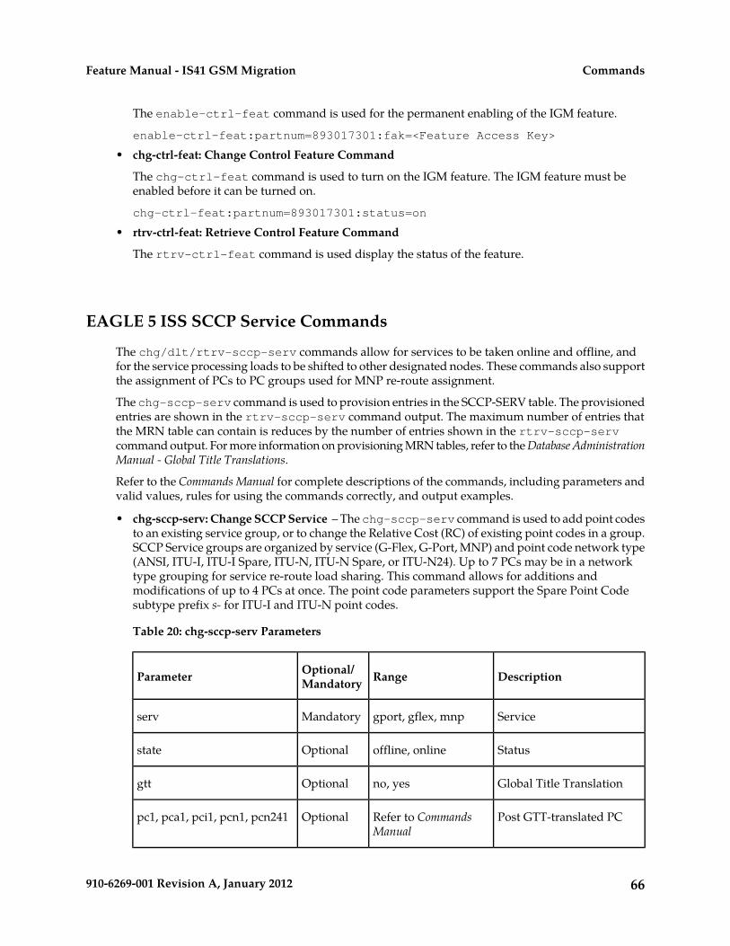
The enable-ctrl-feat command is used for the permanent enabling of the IGM feature.
enable-ctrl-feat:partnum=893017301:fak=<Feature Access Key>
• chg-ctrl-feat: Change Control Feature Command
The chg-ctrl-feat command is used to turn on the IGM feature. The IGM feature must beenabled before it can be turned on.
chg-ctrl-feat:partnum=893017301:status=on
• rtrv-ctrl-feat: Retrieve Control Feature Command
The rtrv-ctrl-feat command is used display the status of the feature.
EAGLE 5 ISS SCCP Service Commands
The chg/dlt/rtrv-sccp-serv commands allow for services to be taken online and offline, andfor the service processing loads to be shifted to other designated nodes. These commands also supportthe assignment of PCs to PC groups used for MNP re-route assignment.
The chg-sccp-serv command is used to provision entries in the SCCP-SERV table. The provisionedentries are shown in the rtrv-sccp-serv command output. The maximum number of entries thatthe MRN table can contain is reduces by the number of entries shown in the rtrv-sccp-servcommand output. For more information on provisioning MRN tables, refer to the Database AdministrationManual - Global Title Translations.
Refer to the Commands Manual for complete descriptions of the commands, including parameters andvalid values, rules for using the commands correctly, and output examples.
• chg-sccp-serv: Change SCCP Service – The chg-sccp-serv command is used to add point codesto an existing service group, or to change the Relative Cost (RC) of existing point codes in a group.SCCP Service groups are organized by service (G-Flex, G-Port, MNP) and point code network type(ANSI, ITU-I, ITU-I Spare, ITU-N, ITU-N Spare, or ITU-N24). Up to 7 PCs may be in a networktype grouping for service re-route load sharing. This command allows for additions andmodifications of up to 4 PCs at once. The point code parameters support the Spare Point Codesubtype prefix s- for ITU-I and ITU-N point codes.
Table 20: chg-sccp-serv Parameters
DescriptionRangeOptional/MandatoryParameter
Servicegport, gflex, mnpMandatoryserv
Statusoffline, onlineOptionalstate
Global Title Translationno, yesOptionalgtt
Post GTT-translated PCRefer to CommandsManual
Optionalpc1, pca1, pci1, pcn1, pcn241
66910-6269-001 Revision A, January 2012
CommandsFeature Manual - IS41 GSM Migration

DescriptionRangeOptional/MandatoryParameter
Relative Cost00-99Optionalrc1
Post GTT-translated PCRefer to CommandsManual
Optionalpc2, pca2, pci2, pcn2, pcn242
Relative Cost00-99Optionalrc2
Post GTT-translated PCRefer to CommandsManual
Optionalpc3, pca3, pci3, pcn3, pcn243
Relative Cost00-99Optionalrc3
Post GTT-translated PCRefer to CommandsManual
Optionalpc4, pca4, pci4, pcn4, pcn244
Relative Cost00-99Optionalrc4
• dlt-sccp-serv: Delete SCCP Service – The dlt-sccp-serv command is used remove entriesfrom the SCCP-SERV table. A single command may remove either a PC from a group, or removethe entire group.
Table 21: dlt-sccp-serv Parameters
DescriptionRangeOptional/MandatoryParameter
Servicegport, gflex, mnpMandatoryserv
Post GTT-translated PCRefer to CommandsManual
Optionalpc1, pca1, pci1, pcn1, pcn241
Post GTT-translated PCRefer to CommandsManual
Optionalpc2, pca2, pci2, pcn2, pcn242
Post GTT-translated PCRefer to CommandsManual
Optionalpc3, pca3, pci3, pcn3, pcn243
Post GTT-translated PCRefer to CommandsManual
Optionalpc4, pca4, pci4, pcn4, pcn244
Yes will delete the entiregroup
No, YesOptionalall
67910-6269-001 Revision A, January 2012
CommandsFeature Manual - IS41 GSM Migration

• rtrv-sccp-serv: Retrieve SCCP Service – The rtrv-sccp-serv command is used to display theSCCP Service application relationship information maintained by the EAGLE 5 ISS. Point codesare grouped by service.
68910-6269-001 Revision A, January 2012
CommandsFeature Manual - IS41 GSM Migration

Chapter
4Feature Configuration
This chapter describes the prerequisites,considerations, and steps to activate the IS41 GSM
Topics:
• Introduction.....70 Migration (IGM) feature. This chapter also includesfeature activation procedures for these features:• EPAP Entity Provisioning.....71
• Prerequisites.....71 • 1100 TPS/DSM for ITU NP• EAGLE 5 ISS HLR Destinations
Configuration.....72 • E5-SM4G Throughput Capacity• MTP Msgs for SCCP Apps• IGM Feature Activation Procedure.....78
• The 1100 TPS/DSM for ITU NP Feature.....81• Activating the E5-SM4G Throughput Capacity
Feature.....86• Adding a Service Module Card.....90• LOCREQ Query Response Activation
Procedure.....97• Service Portability Activation Procedure.....100• MTP Routed Messages for SCCP Applications
Activation Procedure.....101
69910-6269-001 Revision A, January 2012

Introduction
This chapter identifies prerequisites for the IS41 GSM Migration (IGM) feature activation procedureand provides the feature activation procedures for these features:
• IS41 GSM Migration (IGM)• 1100 TPS/DSM for ITU NP• E5-SM4G Throughput Capacity• Service Portability• LOCREQ Query Response• MTP Msgs for SCCP Apps
These feature activation procedures are performed at the EAGLE 5 ISS.
The IGM feature and other related features are optional and are purchased from Tekelec. Contact yourTekelec Sales or Account Representative to determine whether you have purchased a specific featureor for additional information. These features are related to the IGM feature:
• Global Title Translation (GTT)• Enhanced Global Title Translation (EGTT)• Variable-Length Global Title Translation (VGTT)• Mobile Number Portability Circular Route Prevention (MNPCRP)
Note: After a permanently-on feature has been turned on with the enable-ctrl-feat command,the feature cannot be turned off. Because this feature may affect other features or system databases,confirm that a feature license and technical support from Tekelec are available before turning on thisfeature. Contact your Tekelec Sales or Account Representative to verify whether the feature has beenpurchased.
Refer to Dimensioning Guide for EPAP Advanced DB Features Technical Reference for important informationabout the dimensioning rules and the Service Module database capacity requirements.
Summary of Feature Activation
This table summarizes the feature activation attributes for the features in this chapter.
Table 22: Feature Activation Summary
PermanentlyOn?
TemporaryFAK
Available?
Part NumberFeature Name
YesNo893017301IS41 GSM Migration (IGM)
NoYes893007001MNP Circular Route Prevention (MNPCRP)
NoNo8930180011100 TPS/DSM for ITU NP
YesNo893019101E5-SM4G Throughput Capacity
70910-6269-001 Revision A, January 2012
Feature ConfigurationFeature Manual - IS41 GSM Migration

PermanentlyOn?
TemporaryFAK
Available?
Part NumberFeature Name
893019102
NoNo893034301Service Portability
YesNo893038501LOCREQ Query Response
NoNo893017401MTP Msgs for SCCP Apps
Feature Activation Considerations
• After a permanently-on feature has been enabled and turned on with the enable-ctrl-featand chg-ctrl-feat commands, the feature cannot be turned off. Because this feature may affectother features or system databases, confirm that a feature license and technical support from Tekelecare available before turning on this feature. Contact your Tekelec Sales or Account Representativeto verify whether the feature has been purchased.
• Refer to Dimensioning Guide for EPAP Advanced DB Features Technical Reference for importantinformation about the dimensioning rules and the Service Module database capacity requirements.
EPAP Entity Provisioning
It is recommended that EPAP entity (SP or RN) administration not be done until after the point codeand/or subsystem number has been entered into the EAGLE 5 ISS MAP table.
• EPAP-administered entity data can possibly become out-of-sync with the EAGLE 5 ISS MAP tablewhen the creation of point codes and/or subsystem numbers in the MAP table is performed afterEPAP database administration.
• If this mismatch is discovered in real-time operations, a UIM (such as SCCP did not route -DPC not in MAP tbl or SCCP did not route - SS not in MAP tbl) is sent to theEAGLE 5 ISS maintenance terminal.
Prerequisites
The IGM feature activation assumes that Global Title Translation (GTT), Enhanced Global TitleTranslation (EGTT), or Variable-Length Global Title Translation (VGTT) is already provisioned. Referto Database Administration Manual - Global Title Translation for provisioning procedures.
The IGM feature activation assumes that the EPAP software is already configured; refer to EPAPSoftware Configuration in EPAP Administration Manual.
The NT serial number (ent-serial-num) must be entered and locked before IGM can be enabledand turned on.
71910-6269-001 Revision A, January 2012
Feature ConfigurationFeature Manual - IS41 GSM Migration

The IGM feature requires a Service Module card running the VSCCP application prior to turning onthe IGMfeature. The IGM feature cannot be turned on if any of the Service Module cards have lessthan 4 GB of memory installed.
The IGM feature activation assumes that the Service Module cards to be installed are identified.
• Note installed Service Module card locations, if any.• Note available odd-even card slots for Service Module card installation.• Determine Service Module card IP addresses and have them available during the activation
procedure.
For in-service systems, schedule Service Module card replacement in maintenance window that allowsthe reboot of Service Module cards (init-card:loc=<Service Module card location>) oneat a time.
For in-service systems that already have another EPAP-related feature enabled, perform only IGMFeature Activation Procedure to turn on the IGM feature. With another EPAP-related feature enabled,the Service Module cards already contain the Real Time Database ( RTDB).
For new systems, Service Module cards may be rebooted all at one time using theinit-card:appl=vsccp command. For new systems, GTT, EGTT, or VGTT features must be turnedon prior to the reboot of all Service Module cards.
EAGLE 5 ISS HLR Destinations Configuration
This procedure configures tche EAGLE 5 ISS system for Home Location Register (HLR) destinationsbefore activating the EPAP-related feature. This procedure assumes that the EAGLE 5 ISS is an existingsystem in which an EPAP-related feature is being activated. The route to the HLR database may alreadybe configured. Perform this procedure to verify that all HLR destinations for the feature are provisionedand to configure changes, as needed.
Refer to Commands Manual for detailed descriptions of the commands used in this procedure.
Procedure Overview
• Display current PCs, CPCs, DPCs, routes, and linksets using Step 1 through Step 6.• Change current PCs, CPCs, DPCs, routes, linksets, and LIM cards using Step 7 through Step 25.
For detailed information about specific configuration activities in this procedure, refer to these topicsin Database Administration Manual - SS7:
• Point Code Formats• Adding a Point Code to the Self-Identification of the EAGLE 5 ISS• Changing the Self-Identification of the EAGLE 5 ISS• Adding a Destination Point Code• Adding an SS7 Linkset• Adding an SS7 Signaling Link• Adding a Route Containing an SS7 DPC
72910-6269-001 Revision A, January 2012
Feature ConfigurationFeature Manual - IS41 GSM Migration

1. Display the current self-identification characteristics (PC and CPC) of the system using the rtrv-sidcommand.The self-identification characteristics of the system displayed by the rtrv-sid command includethe point code (PC) assigned to the system, the CLLI code of the system, the capability point codeof the STP (CPC), and the type of point codes supported by the system.If the ITUDUPPC (ITU national duplicate point code) feature is on, the ITU national point codealso contains a group code. The group code is a two-character field from aa to zz that is entered asthe last subfield of an ITU national point code, nnnnn-gc (for example, 2112-aa).
2. Display the current destination point codes (DPC) in the Destination point code table using thertrv-dstn command.
3. Display the current route and linkset configuration using the rtrv-rte command.4. If the system point code (pci/pcn) or capability point code to be configured in this procedure is
shown in Step 1, Step 2, or Step 3, choose another point code to configure with this procedure. Ifconfiguring an ITU-N network, continue to Step 5. If configuring a mated application but notconfiguring an ITU-N network, proceed to Step 6. Otherwise, proceed to Step 7.
5. Use the rtrv-stpopts command to display the PC or CPC format when configuring the systempoint code or capability point code of an ITU-N network.The ITU-N point code format option npcfmti determines the format of the ITU-N point code inthe database and how it is displayed in all system outputs. The defined value is shown in theNPCFMTI field displayed in the output of the rtrv-stpopts command.
To change the format of the ITU-N point code, refer to “Point Code Formats” in EAGLE 5 ISSDatabase Administration Manual - SS7.
Continue to Step 6to display mated applications in the database. Otherwise, proceed to Step 7.
6. Display the mated applications in the database using the rtrv-map command.a) If the point code of the system is displayed in the rtrv-map command output , remove the
system point code from the mated application table. Refer to procedure “Removing a MatedApplication” in EAGLE 5 ISS Database Administration Manual - Features.
b) If the point code of the system or capability point code is a destination point code of a route,select a point code that is not in the destination point code table (refer to output in Step 2) andnot the destination point code of a route (refer to output in Step 3).
7. Change the point code of the system and capability point code by network type using procedures"Adding a Point Code to the Self-Identification of the EAGLE 5 ISS" and "Changing theSelf-Identification of the EAGLE 5 ISS" in Database Administration Manual - SS7.
8. Enter a destination point code for the HLR location in the Destination table by network type usingthe ent-dstn command.
Command examples:
ent-dstn:dpci=2-100-2
ent-dstn:dpcn=21112
where::dpc/dpca/dpci/dpcn
Destination point code to add to the database
9. Verify the changes using the rtrv-dstn command and specifying the DPC entered in Step 8.
Command examples:
73910-6269-001 Revision A, January 2012
Feature ConfigurationFeature Manual - IS41 GSM Migration

rtrv-dstn:dpci=2-100-2
rtrv-dstn:dpcn=21112
Example of possible output for the DPCI command example:tekelecstp51 09-08-24 21:16:37 GMT EAGLE 41.0.0
DPCI CLLI BEI ELEI ALIASA ALIASN/N24 DMN2-100-2 -------- no --- -------- ---------- SS7
Example of possible output for the DPCN command example:tekelecstp51 09-08-24 21:16:37 GMT EAGLE 41.0.0
DPCN CLLI BEI ELEI ALIASA ALIASI DMN21112 -------- no --- -------- ------ SS7
10. Enter a linkset with the ent-ls command and assign the linkset to the destination point code bynetwork type.
Command examples:
ent-ls:apci=2-200-2:lsn=ls400001:lst=a
ent-ls:apcn=21122:lsn=ls500001:lst=a
where::apc/apca/apci/apcn
Adjacent point code - the DPC of the adjacent signaling node at the far end of thelinkset
:lsnLinkset name
:lst
Linkset type
11. Verify the changes using the rtrv-ls command and specifying the linkset name.
Command example:
rtrv-ls:lsn=ls400001
rtrv-ls:lsn=ls500001
Example of possible output for lsn400001 command example:tekelecstp51 09-08-24 21:16:37 GMT EAGLE 41.0.0
L3T SLT GWS GWS GWSLSN APCI (SS7) SCRN SET SET BEI LST LNKS ACT MES DIS SLSCI NISls400001 2-200-2 scr1 1 2 no a 0 on off off no onCLLI TFATCABMLQ MTPRSE ASL8RLGHNCXA03W 1 no no L2T L1 PCR PCRLOC PORT SLC TYPE SET BPS MODE TSET ECM N1 N2
Example of possible output for lsn500001 command example:tekelecstp51 09-08-24 21:16:37 GMT EAGLE 41.0.0
L3T SLT GWS GWS GWS LSN APCN (SS7) SCRN SET SET BEI LST LNKS ACT MES DIS SLSCI NISls500001 21122 scr3 1 2 no a 0 on off off no on
74910-6269-001 Revision A, January 2012
Feature ConfigurationFeature Manual - IS41 GSM Migration

CLLI TFATCABMLQ MTPRSE ASL8RLGHNCXA03W 1 no no L2T L1 PCR PCRLOC PORT SLC TYPE SET BPS MODE TSET ECM N1 N2
12. Add the LIM cards to the database using the ent-card command.
Command examples:
ent-card:appl=ccs7itu:loc=1105:type=lime1
ent-card:appl=ccs7itu:loc=1106:type=lime1
where::appl
Specifies that the application is CCS7ITU.:loc
Specifies the slot number for the card.:type
Specifies that the card is a LIME1 card.
13. Enter the E1 interface using the ent-e1 command.
Command examples:
ent-t1:loc=1105:e1port=1
ent-t1:loc=1106:e1port=1
where::loc
Card location or slot as stenciled on the shelf:e1port
E1 card port number
14. Verify the changes using the rtrv-card command with the card location specified.
Command examples:
rtrv-card:loc=1105
rtrv-card:loc=1106
Example of possible output for command example:tekelecstp51 09-08-24 21:16:37 GMT EAGLE 41.0.0
CARD TYPE APPL LSET NAME LINK SLC LSET NAME LINK SLC1105 LIME1 CCS7ITU ls400001 A 00 ------------ B --1106 LIME1 CCS7ITU ls500001 A 00 ------------ B --
15. Assign signaling links to the LIM cards using the ent-slk command.
Command example:
ent-slk:l2tset=1:link=a:loc=1105:lsn=ls400001:slc=0:e1port=1:ts=1
ent-slk:l2tset=1:link=a:loc=1106:lsn=ls500001:slc=0:e1port=1:ts=1
75910-6269-001 Revision A, January 2012
Feature ConfigurationFeature Manual - IS41 GSM Migration

where::l2tset
Level 2 timer set. A signaling link can be assigned to any of the thirty timer sets.:link
Signaling link assigned on the card specified in the loc parameter:loc
Card location to which the signaling link is assigned:lsn
Unique linkset name:slc
Signaling link code. The slc must be unique within the linkset, and must be the sameat both the system location and the distant node.
e1portPort for E1 interface on the E1 card to which the signaling link and timeslot are beingassigned
tsE1 timeslot for the assigned signaling link
Signaling links are the only elements in the database supported directly by a hardware device.When a link is added to a linkset, the link remains in Out-of-Service-Maintenance-Disabled(OOS-MT-DSBLD) state until it is activated; see Step 23.
16. Verify the changes using the rtrv-slk command, specifying the card location and ID of thesignaling link entered in Step 15.
Command examples:
rtrv-slk:loc=1105:link=a
rtrv-slk:loc=1106:link=a
17. Add a route for the new DPC by network type using the ent-rte command.
Command examples:
ent-rte:dpci=2-100-2:lsn=ls400001:rc=10
ent-rte:dpcn=21112:lsn=ls500001:rc=10
where::dpc/dpca/dpci/dpcn
Destination point code of the node to which the traffic is bound:lsn
Linkset name associated with this route:rc
Relative cost or priority of this route
76910-6269-001 Revision A, January 2012
Feature ConfigurationFeature Manual - IS41 GSM Migration

18. Verify the changes using the rtrv-rte command and specifying the destination point code ofthe route.
19. Add a mated application by network type to the database using the ent-map command.
Command examples:
ent-map:grp=grp03:materc=99:mpci=3-200-1:mssn=50:pci=2-100-1:ssn=12:rc=20
ent-map:grp=grp07:materc=99:mpcn=11114:mssn=250:pcn=11112:ssn=12:rc=10
where::grp
Concerned point code broadcast list (CSPC) group name. This parameter specifies thename of a group of point codes that should be notified of the subsystem status. Adifferent CSPC group can be assigned to each mated PC/SSN.
:materc
Mate relative cost:mpc/mpca/mpci/mpcn
Mate remote point code.:mssn
Mate subsystem number – the subsystem address of the backup point code that is toreceive the message
:pci/pcn
ITU international/national point code:rc
Relative cost:ssn
Subsystem number – the subsystem address of the primary point code that is to receivethe message
20. Verify the changes using the rtrv-map command.21. Allow the LIM cards that were entered in Step 12 using the alw-card command.
Command examples:
alw-card:loc=1105
alw-card:loc=1106
This message appears:
tekelecstp51 09-08-24 21:16:37 GMT EAGLE 41.0.0Card has been allowed.
22. Verify In-Service-Normal (IS-NR) state of the cards using the rept-stat-card command.23. Activate the signaling links entered in Step 15 using the act-slk command.
Command examples:
act-slk:loc=1105:link=a
77910-6269-001 Revision A, January 2012
Feature ConfigurationFeature Manual - IS41 GSM Migration

act-slk:loc=1106:link=a
The link changes state from Out-of-Service-Maintenance-Disabled (OOS-MT-DSBLD) toIn-Service-Normal (IS-NR). The output confirms the activation.
tekelecstp51 09-08-24 21:16:37 GMT EAGLE 41.0.0Activate Link message sent to card
24. Verify In-Service-Normal (IS-NR) state of the signaling link using the rept-stat-slk command.
Command examples:
rept-stat-slk:loc=1105
rept-stat-slk:loc=1106
25. Display the new LIM cards in the database using the rtrv-card command.
Example of a possible output:tekelecstp51 09-08-24 21:16:37 GMT EAGLE 41.0.0CARD TYPE APPL LSET NAME LINK SLC LSET NAME LINK SLC1105 LIME1 CCS7ITU ls400001 A 00 ------------ B --1106 LIME1 CCS7ITU ls500001 A 00 ------------ B --
26. Back up the database changes using the chg-db:action=backup:dest=fixed command.The following messages appear, the active Maintenance and Administration Subsystem Processor(MASP) appears first.BACKUP (FIXED): MASP A - Backup starts on active MASP.BACKUP (FIXED): MASP A - Backup on active MASP to fixed disk complete.BACKUP (FIXED): MASP A - Backup starts on standby MASP.BACKUP (FIXED): MASP A - Backup on standby MASP to fixed disk complete.
The HLR destinations are now configured and ready for activation of the EPAP-related feature.
IGM Feature Activation Procedure
Use this procedure to enable, turn on, and configure the IS41 GSM Migration (IGM) feature.
Refer to the Commands Manual for complete descriptions of the commands that are used in thisprocedure, including parameters and valid values, rules for using the commands correctly, and outputexamples.
CAUTION: Before starting this procedure, contact the Customer Care Center for assistancein performing the feature activation procedure. Do not proceed without consulting withTechnical Services.
1. Enter the enable-ctrl-feat command to enable the IGM feature:enable-ctrl-feat:partnum=893017301:fak=<Feature Access Key>
2. Enter the chg-ctrl-feat command to turn on the IGM feature:chg-ctrl-feat:partnum=893017301:status=on
3. Enter the default country code and default network destination code to convert the nature of addressindicator (NAI) of MSISDNs to the international format (nai=intl), by entering the chg-stpoptscommand.
78910-6269-001 Revision A, January 2012
Feature ConfigurationFeature Manual - IS41 GSM Migration

For example:
chg-stpopts:defcc=1:defndc=38:dsmaud=on:npcfmti=2-9-2-1
where::defcc
Default country code:defndc
Default network destination code:dsmaud
Service Module card checksum audit running state (on or off):npcfmti
ITU National Point Code Format Identifier, which identifies how the ITU nationalpoint code is entered into the database and how it is displayed in all EAGLE 5 ISSoutputs. The ITU national point code is a 14-bit integer.
4. Verify the new country code and network destination code, using the rtrv-stpopts command.5. Change the GSM system options in the database, using the chg-gsmopts command.
For example:
chg-gsmopts:defmapvr=2:is412gsm=34:msrsndig=ccrndn:srfaddr=23448:srfnai=7:srfnp=15
where::defmapvr
Default MAP versionis412gsm
IS41 to GSM migration prefix:msrndig
Routing Number to be used as is or to be concatenated with the MSISDN:srfaddr
Entity address of the MNP_SRF node:srfnai
Nature of Address Indicator value of the MNP_SRF:srfnp
Numbering Plan value of the MNP_SRF
6. Verify the changes, using the rtrv-gsmopts command to display all GSM system option valuesfrom the database.
7. Change the IS41 system options in the database, using the chg-is41opts command.8. Verify the changes using the rtrv-is41opts command to display all IS41 system option values
from the database.9. Add Routing Number prefixes for the operating network, using the ent-homern command. Add
Home RNs that are prefixed to DNs for incoming INP MR messages. Up to 100 Routing Numberprefixes for the operating network can be added to the HOMERN table.
79910-6269-001 Revision A, January 2012
Feature ConfigurationFeature Manual - IS41 GSM Migration

For example:
ent-homern:rn=34
where::rn
Home routing number prefix. Parameter value is 1 to 15 hex digits (0-F).
10. Verify the changes using the rtrv-homern command to retrieve a list of Routing Number prefixesthat belong to the operating network.
11. Display the list of administered service selector combinations, using the rtrv-srvsel command.Avoid lengthy output by using various parameter combinations to filter the list . The ServiceSelector table can have over 1,000 entries.
12. Enter the IGM service selectors by network type, if necessary, using the ent-srvsel command.This command assigns applicable service selectors required to specify the service entry for ServiceModule card services.
For example:
ent-srvsel:gtii=4:nai=intl:np=e164:serv=mnp:snai=intl:snp=e164:ssn=9:tt=1
where::gtii
Global title indicator, ITU international:nai
Nature of address indicator:np
Numbering plan:serv
Service feature:snai
International Service Nature of Address Indicator:snp
Service numbering plan:ssn
Subsystem number:tt
Translation type
13. Verify the changes, using the rtrv-srvsel command to retrieve the list of administered serviceselector combinations.Avoid lengthy output by using various parameter combinations to filter the list . The ServiceSelector table can have over 1,000 entries.
For example:
80910-6269-001 Revision A, January 2012
Feature ConfigurationFeature Manual - IS41 GSM Migration

rtrv-srvsel:gtii=2
rtrv-srvsel:gtii=4
where:gtii
Global title indicator, ITU international
CAUTION: GTT, EGTT, and VGTT traffic is routed based on the global titles in theOAM database while G-Flex, G-Port, A-Port, and INP traffic is routed based on theglobal title in the RTDB. Rebooting a Service Module card running the VSCCPapplication causes both the OAM databases and the RTDB on the Service Module cardto reload.
14. Verify that the Service Module card returns to In-Service-Normal (IS-NR) state, using therept-stat-card command.
WARNING: Do not proceed until In-Service-Normal (IS-NR) state of the ServiceModule card is restored.
15. After In-Service-Normal (IS-NR) state of the Service Module card is restored and verified usingthe rept-stat-card command, repeat Step 14 for each Service Module card in the system.
16. Set the IGM service state online using chg-sccp-serv:serv=mnp:state=online.17. Confirm that the activation steps were successful by performing the following verifications:
• Verify that all Service Module cards are loaded and are in In-Service-Normal (IS-NR) state,using the rept-stat-sccp command.
• Verify that all Service Module cards and the EPAP are connected and operational, using therept-stat-mps command.
• Verify that database levels are identical for the EPAP PDB and RTDB. Display the RTDBs onthe Service Module cards, using rept-stat-db:display=all .
18. Back up the database changes using the chg-db:action=backup:dest=fixed command.The following messages appear, the active Maintenance and Administration Subsystem Processor(MASP) appears first.BACKUP (FIXED): MASP A - Backup starts on active MASP.BACKUP (FIXED): MASP A - Backup on active MASP to fixed disk complete.BACKUP (FIXED): MASP A - Backup starts on standby MASP.BACKUP (FIXED): MASP A - Backup on standby MASP to fixed disk complete.
The IS41 GSM Migration (IGM) feature is now enabled, turned on, and operating in the system.
The 1100 TPS/DSM for ITU NP Feature
When only DSM cards or a mixture of DSM cards with E5-SM4G or E5-SM8G-B cards (Service Modulecards) are equipped in the system, all of the cards are normally rated at 850 transactions per second
81910-6269-001 Revision A, January 2012
Feature ConfigurationFeature Manual - IS41 GSM Migration

(TPS). The 1100 TPS/DSM for ITU NP feature increases the TPS rate for a Service Module card from850 TPS to 1100 TPS.
The feature can be enabled when the equipped Service Module cards include DSM cards and at leastone of the EPAP-related features listed in Table 24: Feature Prerequisites is enabled and turned on.
When the maximum number of Service Module cards is installed in the EAGLE 5 ISS, the maximumprocessing capacity of SCCP traffic for an EAGLE 5 ISS processing traffic for EPAP-related featuresis increased to 34,100 TPS.
The increased capacity to 1100 TPS per DSM card assumes incoming traffic consists of at least 30% ofGTT routed traffic that does not require EPAP-based lookup. If more than 70% of incoming trafficrequires EPAP-based lookup, Group Ticket Voucher (TVG) may shut down and overall TVG capacityof 1100 TPS for the card may not be met. E5-SM8G-B cards are inhibited if Group Ticket Voucher(TVG) is enabled.
The 1100 TPS/DSM for ITU NP feature must be enabled using the feature part number 893018001 anda feature access key (FAK). Based on the feature part number and the serial number of the EAGLE 5ISS, the feature access key is site-specific. The 1100 TPS/DSM for ITU NP feature cannot be enabledwith a temporary feature access key.
Note: The feature access key for the 1100 TPS/DSM for ITU NP feature is provided by Tekelec whenthe feature is purchased. Contact your Tekelec Sales Representative or Account Representative beforebeginning the feature configuration procedure if you do not have the feature access key for this feature.
After the 1100 TPS/DSM for ITU NP feature has been enabled, the feature must be turned on to beginoperation in the system. The feature is an On/Off feature which means that the feature can be turnedoff after it has been turned on.
System Prerequisites
Before the 1100 TPS/DSM for ITU NP feature can be enabled, the prerequisites listed in Table 23: SystemPrerequisites are required in the system.
Table 23: System Prerequisites
Verification and ProvisioningPrerequisite
Enter the rtrv-serial-num command todisplay the serial number and its lock status.
For new installations, the system serial numbermust be verified and locked. The system isshipped with an unlocked serial number. The If a serial number is displayed, verify that the
serial number is correct for the system. The systemserial number can be changed if necessary andmust be locked after the system is on-site. serial number is shown on a label affixed to the
control shelf (shelf 1100).For systems that are being upgraded, the serialnumber has already been verified and locked. If the displayed serial number is correct and
locked, no action is necessary.
If the displayed serial number is correct and notlocked, enter the ent-serial-num commandWITH the lock=yes parameter, and specify theserial number that is shown on the control shelflabel.
If no serial number is displayed,
82910-6269-001 Revision A, January 2012
Feature ConfigurationFeature Manual - IS41 GSM Migration

Verification and ProvisioningPrerequisite
• Enter the ent-serial-num commandWITHOUT the lock parameter, and specify theserial number that is shown on the controlshelf label.
• Enter the rtrv-serial-num command andverify that the correct serial number wasentered.
• Enter the ent-serial-num command againWITH the correct serial number and thelock=yes parameter.
If a serial number is displayed or entered andlocked that does not match the number on thecontrol shelf, contact the Customer Care Center forassistance.
Enter the rtrv-feat command.The GTT feature must on in the system.
If the GTT feature is on, the gtt=on entry appearsin the output.
If the gtt=off entry appears in the output, usethe procedures in Database Administration Manual– Global Title Translation to turn on and provisionthe GTT feature and any related features andfunctions.
Feature Prerequisites
Before the 1100 TPS/DSM for ITU NP feature can be enabled, the prerequisites shown in Table 24:Feature Prerequisites are required in the system.
Table 24: Feature Prerequisites
Verification and ProvisioningPrerequisite
Enter the rept-stat-gpl:gpl=vsccpcommand and the
Service Module cards running the VSCCPapplication must be equipped. The cards can beall DSM cards, or a mixture of DSM cards with rept-stat-gpl:gpl=sccphc command to list
the Service Module cards in the system.E5-SM4G or E5-SM8G-B cards. At least one DSMcard must be installed. If the number of cards is not sufficient, use the
procedure Adding a Service Module Card to addService Module cards.
Enter the rtrv-stpopts command.The ANSIGFLEX system option cannot be set toYes. Verify that the ANSIGFLEX entry does not appear
in the command output or that the ANSIGFLEXentry shows a value of no.
83910-6269-001 Revision A, January 2012
Feature ConfigurationFeature Manual - IS41 GSM Migration

Verification and ProvisioningPrerequisite
Enter the rtrv-ctrl-feat command.The LNP feature cannot be on in the system.
If the LNP feature is on, shown with a quantitygreater than zero for the LNP ported TNs entryin the command output, the 1100 TPS/DSM forITU NP feature cannot be enabled.
Enter the rtrv-ctrl-feat command andverify that an entry for at least one of the listed
At least one of the following EPAP-relatedfeatures must be enabled and turned on:
EPAP-related features with Status on is presentin the output.
• G-Port• A-Port
If none of the listed EPAP-related features are on,use the procedures in the Feature Manual of the
• INP• AINPQ
EPAP-related feature to be used to enable andturn on the appropriate EPAP-related feature.
• IGM• EIR• IDP Relay• V-Flex• IAR (NP, ASD, GRN)• MO-based GSM SMS NP• MO-based IS41SMS NP• TIF (NP, ASD, GRN, Number Substitution, TIF
Subscr CgPN Blacklist)
This section provides the following procedures for the 1100 TPS/DSM for ITU NP feature:
• Enable the 1100 TPS/DSM for ITU NP Feature• Turn On the 1100 TPS/DSM for ITU NP Feature• Turn Off the 1100 TPS/DSM for ITU NP Feature
Refer to Commands Manual for descriptions of the commands used in the procedures including parameternames, valid parameter values, rules for using the commands, and output examples.
Enable the 1100 TPS/DSM for ITU NP Feature
This procedure is used to enable the 1100 TPS/DSM for ITU NP feature.
1. Enable the 1100 TPS/DSM for ITU NP feature with part number 893018001 and the feature accesskey.
enable-ctrl-feat:partnum=893018001:fak=<feature access key>
2. Verify the change by entering the rtrv-ctrl-feat command with the 1100 TPS/DSM for ITUNP feature part number 893018001.
rtrv-ctrl-feat:partnum=893018001
rlghncxa03w 09-08-24 21:15:37 EST EAGLE 40.1.0The following features have been permanently enabled: Feature Name Partnum Status Quantity HC-MIM SLK Capacity 893012707 on 64Prepaid SMS Intercept Ph1 893006701 on ----
84910-6269-001 Revision A, January 2012
Feature ConfigurationFeature Manual - IS41 GSM Migration

1100 TPS/DSM for ITU NP 893018001 off ---- ;
3. Back up the changes using the chg-db:action=backup:dest=fixed command.The following messages appear, the active Maintenance and Administration Subsystem Processor(MASP) appears first.BACKUP (FIXED) : MASP A - Backup starts on active MASP. BACKUP (FIXED) : MASP A - Backup on active MASP to fixed disk complete. BACKUP (FIXED) : MASP A - Backup starts on standby MASP. BACKUP (FIXED) : MASP A - Backup on standby MASP to fixed disk complete.
Turn On the 1100 TPS/DSM for ITU NP Feature
This procedure is used to turn on the 1100 TPS/DSM for ITU NP feature, after it has been enabled orturned off.
Note: If the EPAP-based traffic is higher than 70% of all traffic on the EAGLE 5 ISS, the DSM cardperformance may not reach 1100 TPS per DSM card.
1. Enter the chg-ctrl-feat command the first time and specify the 1100 TPS/DSM for ITU NPfeature part number 893018001and the status=on parameter value.
chg-ctrl-feat:partnum=893018001:status=on
The following message is displayed:CAUTION: Rated TPS for this feature supports an engineered GTTtraffic mix of no more than 70 percent EPAP-based traffic.Re-enter the command within 30 seconds to confirm change.
2. Re-enter the command the second time within 30 seconds to turn on the 1100 TPS/DSM for ITUNP feature.
chg-ctrl-feat:partnum=893018001:status=on
3. Verify the change by entering the rtrv-ctrl-feat command with the 1100 TPS/DSM for ITUNP feature part number.
rtrv-ctrl-feat:partnum=893018001
rlghncxa03w 09-08-24 21:15:37 EST EAGLE 40.1.0The following features have been permanently enabled: Feature Name Partnum Status Quantity HC-MIM SLK Capacity 893012707 on 64Prepaid SMS Intercept Ph1 893006701 on ----1100 TPS/DSM for ITU NP 893018001 on ---- ;
4. Back up the database changes using the chg-db:action=backup:dest=fixed command.The following messages appear, the active Maintenance and Administration Subsystem Processor(MASP) appears first.BACKUP (FIXED): MASP A - Backup starts on active MASP.BACKUP (FIXED): MASP A - Backup on active MASP to fixed disk complete.BACKUP (FIXED): MASP A - Backup starts on standby MASP.BACKUP (FIXED): MASP A - Backup on standby MASP to fixed disk complete.
85910-6269-001 Revision A, January 2012
Feature ConfigurationFeature Manual - IS41 GSM Migration

Turn Off the 1100 TPS/DSM for ITU NP Feature
This procedure is used to turn off the 1100 TPS/DSM for ITU NP feature, after it has been enabledand turned on.
1. Enter the chg-ctrl-feat command the first time and specify the 1100 TPS/DSM for ITU NPfeature part number 893018001 and the status=off parameter value.
chg-ctrl-feat:partnum=893018001:status=off
The following message is displayed:CAUTION: This command decreases the total TPS of the SCCP system from 1100 to 850 TPS for each DSM card.
2. Re-enter the command the second time within 30 seconds to turn off the 1100 TPS/DSM for ITUNP feature.
3. Back up the database changes using the chg-db:action=backup:dest=fixed command.The following messages appear, the active Maintenance and Administration Subsystem Processor(MASP) appears first.BACKUP (FIXED): MASP A - Backup starts on active MASP.BACKUP (FIXED): MASP A - Backup on active MASP to fixed disk complete.BACKUP (FIXED): MASP A - Backup starts on standby MASP.BACKUP (FIXED): MASP A - Backup on standby MASP to fixed disk complete.
Activating the E5-SM4G Throughput Capacity Feature
The E5-SM4G Throughput Capacity feature quantities are used to increase the processing capacity ofthe E5-SM4G card, the E5-SM8G-B card, and the system SCCP traffic for an EAGLE 5 ISS that containsE5-SM4G or E5-SM8G-B cards only. DSM Service Module cards are not affected. The achievable TPSmaximums are shown in Table 25: Maximum E5-SM4G, E5-SM8G-B, and System TPS Capacity.
Table 25: Maximum E5-SM4G, E5-SM8G-B, and System TPS Capacity
Maximum System TPS CapacityMaximum TPSCapacity perE5-SM8G -B Card
Maximum TPSCapacity perE5-SM4G Card
Feature QuantityPart Number
96,875 TPS with one or moreEPAP-related features and 31+1 cardswith EPAP running on T1200 AS
31253125893019101 - FeatureQuantity 5000
50005000 • 150,000 TPS with no EPAP-relatedor ELAP-related feature trafficand 31+1 cards
• 120,000 TPS with G-Flex and theANSIGFLEX STP option and 24+1cards
86910-6269-001 Revision A, January 2012
Feature ConfigurationFeature Manual - IS41 GSM Migration

Maximum System TPS CapacityMaximum TPSCapacity perE5-SM8G -B Card
Maximum TPSCapacity perE5-SM4G Card
Feature QuantityPart Number
• 155,00 TPS with G-Flex and theANSIGFLEX STP option and 31+1cards with EPAP running onT1200 AS
• 40,000 TPS with ELAP and 8+1cards
• 85,000 TPS with ELAP and 17+1cards
68006800893019102 - FeatureQuantity 6800 • 210,800 TPS with no EPAP-related
or ELAP-related feature trafficand 31+1 cards
• 210,800 TPS with one or moreEPAP-related features and 31+1cards with EPAP running onT1200 AS
• 54,400 TPS with ELAP and 8+1cards
• 115,600 TPS with ELAP and 17+1cards
For E5-SM4G:100006800893019103 - FeatureQuantity 10000
• 210,800 TPS with no EPAP-relatedor ELAP-related feature trafficand 31+1 cards
• 210,800 TPS with one or moreEPAP-related features and 31+1cards with EPAP running onT1200 AS
• 54,400 TPS with ELAP and 8+1cards
• 115,600 TPS with ELAP and 17+1cards
For E5-SM8G-B:
• 310,000 TPS with no EPAP-relatedor ELAP-related feature trafficand 31+1 cards
• 310,000 TPS with one or moreEPAP-related features and 31+1cards with EPAP running onT1200 AS
87910-6269-001 Revision A, January 2012
Feature ConfigurationFeature Manual - IS41 GSM Migration

Maximum System TPS CapacityMaximum TPSCapacity perE5-SM8G -B Card
Maximum TPSCapacity perE5-SM4G Card
Feature QuantityPart Number
• 80,000 TPS with ELAP and 8+1cards
• 170,000 TPS with ELAP and 17+1cards
An E5-SM4G Throughput Capacity quantity feature must be enabled using an E5-SM4G ThroughputCapacity feature part number (893019101, 893019102, or 893019102) and a feature access key.
The feature access key is based on the feature part number and the serial number of the EAGLE 5 ISS,making the feature access key site-specific.
Note: The E5-SM4G Throughput Capacity quantity feature must be purchased to receive the featureaccess key used to enable the feature. Contact your Tekelec Sales Representative or AccountRepresentative before beginning this procedure if you have purchased the E5-SM4G ThroughputCapacity quantity feature, but do not have the feature access key. A temporary feature access key isnot available for this feature.
After an E5-SM4G Throughput Capacity feature is enabled and turned on, the E5-SM4G ThroughputCapacity feature cannot be turned off. When the E5-SM4G Throughput Capacity feature is enabled,it is permanently enabled. The E5-SM4G Throughput Capacity feature cannot be temporarily enabled.
System Prerequisites
Before the E5-SM4G Throughput Capacity feature can be enabled, the prerequisites listed in Table 26:System Prerequisites are required in the system.
Table 26: System Prerequisites
Verification and ProvisioningPrerequisite
Enter the rtrv-serial-num command to display the serialnumber and its lock status.
For new installations, the system serialnumber must be verified and locked.The system is shipped with an unlocked Verify that the displayed serial number is correct for the
system. The serial number is shown on a label affixed to thecontrol shelf (shelf 1100).
serial number. The serial number canbe changed if necessary and must belocked after the system is on-site.
If no serial number is displayed, or if the displayed serialnumber is not locked, refer to the ent-serial-numFor systems that are being upgraded,
the serial number has already beenverified and locked. command description in Commands Manual for instructions
to enter and lock the serial number.
Enter the rtrv-feat command.The GTT feature must on in the system.
If the GTT feature is on, the gtt=on entry appears in theoutput.
If the gtt=off entry appears in the output, use the proceduresin Database Administration Manual – Global Title Translation
88910-6269-001 Revision A, January 2012
Feature ConfigurationFeature Manual - IS41 GSM Migration

Verification and ProvisioningPrerequisite
to turn on and provision the GTT feature and any relatedfeatures and functions.
E5-SM4G Throughput Capacity Feature Prerequisite
Before the E5-SM4G Throughput Capacity feature can be enabled, the prerequisite shown in Table 27:E5-SM4G Throughput Capacity Feature Prerequisite is required in the system.
Table 27: E5-SM4G Throughput Capacity Feature Prerequisite
Verification and ProvisioningPrerequisite
Enter the rept-stat-gpl:gpl=sccphccommand to list the E5-SM4G cards andE5-SM8G-B cards in the system.
E5-SM4G cards or E5-SM8G-B cards running theVSCCP application must be equipped.
The required number of cards depends on thedesired total system TPS to be achieved by the If the number of cards is not sufficient, use the
procedure in Adding a Service Module Card to addE5-SM4G cards or E5-SM8G-B cards.
cards. See Table 25: Maximum E5-SM4G,E5-SM8G-B, and System TPS Capacity.
The following procedure explains how to enable an E5-SM4G Throughput Capacity quantity feature.
Note: After a quantity feature has been enabled, a feature for a higher quantity can be enabled; afeature for a lower quantity cannot be enabled. Quantity features are automatically turned on whenthey are enabled.
Refer to Commands Manual for complete descriptions of the commands used in this procedure, includingparameter names, valid parameter values, rules for using the commands, and output examples.
1. Display the status of the features that are controlled by feature access keys. Enter thertrv-ctrl-feat command. rlghncxa03w 09-07-29 16:40:40 EST EAGLE5 41.1.0 The following features have been permanently enabled: Feature Name Partnum Status Quantity HC-MIM SLK Capacity 893012707 on 64 E5-SM4G Throughput Cap 893019101 on 5000;
• If the rtrv-ctrl-feat output shows that the correct E5-SM4G Throughput Capacity quantityfeature is enabled and its status is on, no further action is necessary.
• If no E5-SM4G Throughput Capacity feature quantity is enabled or a higher quantity needs tobe enabled, continue with Step 2.
2. Enable the E5-SM4G Throughput Capacity quantity feature by entering the enable-ctrl-featcommand with the correct part number and FAK for the desired quantity.
3. Verify the status of the E5-SM4G Throughput Capacity quantity feature by entering thertrv-ctrl-feat command with the feature part number that was enabled (893033501, 893019102,or 893019103) in Step 2.rtrv-ctrl-feat:partnum=893019102
rlghncxa03w 09-08-29 16:40:40 EST EAGLE5 41.1.0 The following features have been permanently enabled: Feature Name Partnum Status Quantity
89910-6269-001 Revision A, January 2012
Feature ConfigurationFeature Manual - IS41 GSM Migration

HC-MIM SLK Capacity 893012707 on 64 E5-SM4G Throughput Cap 893019102 on 6800;
4. Back up the changes using the chg-db:action=backup:dest=fixed command.The following messages appear, the active Maintenance and Administration Subsystem Processor(MASP) appears first.BACKUP (FIXED): MASP A - Backup starts on active MASP.BACKUP (FIXED): MASP A - Backup on active MASP to fixed disk complete.BACKUP (FIXED): MASP A - Backup starts on standby MASP.BACKUP (FIXED): MASP A - Backup on standby MASP to fixed disk complete.
Adding a Service Module Card
This procedure is used to add Service Module cards to the database to support GTT-related featuresand EPAP-related features.
EPAP-related features require Service Module cards running the VSCCP application. The followingcards can be used as Service Module cards running the VSCCP application in the system:
• DSM 4G – a Service Module card with 4 gigabytes of memory and supports Group Ticket Voucher(TVG) and Message Flow Control (MFC)
• E5-SM4G - a Service Module card with 4 gigabytes of memory and supports TVG and MFC• E5-SM8G-B - a Service Module card with 8 gigabytes of memory and supports only MFC
The system can contain a maximum of 32 (31+1) Service Module cards for EPAP-related features withEPAP running on a T1200 AS:
• The following Warning appears when more than 25 Service Module cards have been provisionedin the system and the enable-ctrl-feat command is entered to enable the first EPAP-relatedfeature in the system:Warning: The Eagle must be connected to an EPAP T1200 or higher
• The following Caution appears when the ent-card commend is entered to add the 26th ServiceModule card to the database and any EPAP-related feature is enabled in the system:CAUTION: Please ensure EPAP Application Server is running on hardware supporting 32 SCCP cards e.g.: T1200. Re-enter command within 30 seconds to confirm change.
Refer to Dimensioning Guide for EPAP Advanced DB Features for important information on dimensioningrules and Service Module card database capacity requirements.
A Service Module card occupies two card slots. A Service Module card can be inserted in only anodd/even numbered pair of empty card slots of an EAGLE 5 ISS shelf. The even-numbered card slotto the right of the odd-numbered slot where the Service Module card is to be inserted must be empty.A Service Module card cannot be inserted in slots 09 and 10 because slots 09 and 10 of each shelfcontain HMUX cards, HIPR cards, or HIPR2 cards. The Service Module card is connected to the networkthrough the odd-numbered card slot connector.
Note: Service Module cards can be inserted only in slots 01, 03, 05, 07, and 11 of the control shelf(1100).
90910-6269-001 Revision A, January 2012
Feature ConfigurationFeature Manual - IS41 GSM Migration

Table 28: Service Module Card Locations
Empty Card LocationLocation of the Service Module Card
Slot 02Slot 01
Slot 04Slot 03
Slot 06Slot 05
Slot 08Slot 07
Slot 12Slot 11
Slot 14Slot 13
Slot 16Slot 15
Slot 18Slot 17
Prerequisites
Before a Service Module card can be added, the prerequisites in Table 29: System Prerequisites for Addinga Service Module Card must be present in the system.
Table 29: System Prerequisites for Adding a Service Module Card
Verification and ActionsPrerequisite
Enter the rtrv-shlf command.The shelf to which the card is tobe added must already beprovisioned in the database. If the shelf is not in the database, refer to the procedure for adding
a shelf in Database Administration Manual – System Management.
Enter the rtrv-card command.The odd/even slots in which thecard will be inserted must not If a slot has a card assigned to it, use the dlt-card command to
remove the card from the database. Refer to the dlt-cardcommand description in Commands Manual.
have a card already assigned inthe database.
Enter the rtrv-feat command to display the GTT feature status.The GTT feature must be on.
If the GTT feature is on, the gtt=on entry appears in the output.
If the gtt=off entry appears in the output, use the procedures inDatabase Administration Manual - GTT to turn on and provision theGTT feature and any other GTT-related features and functions thatwill be used in the system.
91910-6269-001 Revision A, January 2012
Feature ConfigurationFeature Manual - IS41 GSM Migration

Verification and ActionsPrerequisite
Use visual inspection or contact the for assistance to determine theEPAP hardware type.
To add more than 25 ServiceModule cards to the database,the EPAP connected to theEAGLE 5 ISS must be runningon a T1200 AS.
Before an E5-SM4G Service Module card can be added, the prerequisite in Table 30: Prerequisite forAdding an E5-SM4G Service Module Card must be present in the system.
Table 30: Prerequisite for Adding an E5-SM4G Service Module Card
Verification and ActionsPrerequisite
Enter the rept-stat-gpl:gpl=hipr command and therept-stat-gpl:gpl=hipr2 command to list the installed HIPRcards and HIPR2 cards in the system.
Slots 09 and 10 in the shelf towhich the E5-SM4G card will beadded must contain either HIPRcards or HIPR2 cards. If the shelf does not contain HIPR cards or HIPR2 cards, refer to
procedures in Installation Manual - EAGLE 5 ISS to install HIPRcards or HIPR2 cards in the shelf.
Before an E5-SM8G-B Service Module card can be added, the prerequisites in Table 31: Prerequisites forAdding an E5-SM8G-B Service Module Card must be present in the system.
Table 31: Prerequisites for Adding an E5-SM8G-B Service Module Card
Verification and ActionsPrerequisite
Enter the rept-stat-gpl:gpl=hipr commandand the rept-stat-gpl:gpl=hipr2 command
Slots 09 and 10 in the shelf to which theE5-SM8G-B card will be added must contain eitherHIPR cards or HIPR2 cards. to list the installed HIPR cards and HIPR2 cards
in the system.
If the shelf does not contain HIPR cards or HIPR2cards, refer to procedures in Installation Manual -EAGLE 5 ISS to install HIPR cards or HIPR2 cardsin the shelf.
If fan trays are not installed, refer to InstallationManual - EAGLE 5 ISS for the fan installationprocedure.
Fan trays must be installed.
Enter the rtrv-feat command to display thestatus of the Cooling Fan feature (FAN).
The Cooling Fan feature (FAN) must be on.
If FAN = off in the rtrv-feat output, refer toprocedures in Database Administration Manual -
92910-6269-001 Revision A, January 2012
Feature ConfigurationFeature Manual - IS41 GSM Migration

Verification and ActionsPrerequisite
System Management to turn on the Cooling Fanfeature (FAN).
Enter the rtrv-stpopts command to displaythe status of the Message Flow Control (MFC)option.
The Message Flow Control (MFC) option must beon.
Refer to procedures in Database AdministrationManual - System Management to turn on theMessage Flow Control (MFC) option.
Refer to Commands Manual for complete descriptions of the commands used in this procedure. Thecomplete descriptions include valid parameter values and output examples.
1. Display the cards in the system by entering the rtrv-card command. Odd-even pairs of cardlocations that do not contain cards (are not listed in the output) and do not contain HMUX, HIPR,or HIPR2 cards can be used for Service Module cards. rlghncxa03w 08-03-15 16:34:56 EST EAGLE 39.2.0 CARD TYPE APPL LSET NAME LINK SLC LSET NAME LINK SLC 1201 LIMDS0 SS7ANSI LS1 A 0 LS1 B 1102 DSM VSCCP ------------ A -- ------------ B -- 1113 GPSM OAM 1114 TDM-A 1115 GPSM OAM 1116 TDM-B 1117 MDAL
;
2. Verify that the Service Module card to be added has been physically installed in the correct cardlocation and the required cabling is installed to connect the card to the EPAP.
CAUTION: If the version of the BPDCM GPL on the Service Module card does notmatch the BPDCM GPL version in the database when the Service Module card isinserted into the card slot, UAM 0002 is generated indicating that these GPL versionsdo not match. If UAM 0002 has been generated, perform the alarm clearing procedurefor UAM 0002 in the Unsolicited Alarm and Information Messages manual beforeproceeding with this procedure.
3. Perform this step only if the card being added will be the 26th Service Module card in the system.
If the card is NOT the 26th Service Module card, continue to Step 4.
Note: The same ent-card command must be entered twice within 30 seconds to complete theprovisioning of the card.
a) Enter the ent-card command the first time for the 26th card.ent-card:loc=<card location>:type=dsm:appl=vsccp
When the command executes the first time and any EPAP-related feature is enabled, the followingcaution appears :CAUTION: Please ensure EPAP Application Server is running on hardware supporting 32 SCCP cards e.g.: T1200. Re-enter command within 30 seconds to confirm change.
93910-6269-001 Revision A, January 2012
Feature ConfigurationFeature Manual - IS41 GSM Migration

b) Enter the ent-card command a second time for the 26th card to complete the provisioning ofthe card.
c) Go to Step 5.
4. Add the Service Module card to the database, using the ent-card command.ent-card:loc=<card location>:type=dsm:appl=vsccp
5. For an E5-SM4G or E5-SM8G-B card, verify the temperature threshold settings by performing the“Changing the High-Capacity Card Temperature Alarm Thresholds” procedure in DatabaseAdministration Manual - SS7.
6. Verify the change by entering the rtrv-card command with the card location specified.rtrv-card:loc=<card location>
rlghncxa03w 08-03-15 16:34:56 EST EAGLE 39.2.0 CARD TYPE APPL LSET NAME LINK SLC LSET NAME LINK SLC 1301 DSM VSCCP ------------ A -- ------------ B ;
7. Display the current IP link parameters associated with the Service Module card in the database byentering the rtrv-ip-lnk command.RLGHNCXA03W 09-08-24 21:14:37 GMT EAGLE 41.0.0 LOC PORT IPADDR SUBMASK DUPLEX SPEED MACTYPE AUTO MCAST 1107 A ------- -------- HALF 10 DIX NO NO 1107 B ------- -------- HALF 10 DIX NO NO
8. Enter the IP address and other parameter values associated with the Service Module card in thedatabase using the chg-ip-lnk command.
For example, enter:
chg-ip-lnk:loc=1107:port=a:duplex=half:ipaddrr=192.168.122.1:mactype=dix:speed=100:mcast=yes:submask=255.255.255.0
chg-ip-lnk:loc=1107:port=b:duplex=half:ipaddrr=192.168.123.1:mactype=dix:speed=10:mcast=yes:submask=255.255.255.0
where::loc
Card location or slot number of the Service Module card in the EAGLE 5 ISS:port
Ethernet interface Port ID - the physical interface of the Service Module card:ipaddr
IP address for the specified port. This is a TCP/IP address expressed in standard dotnotation. IP addresses consist of the network number of the system and the uniquehost number.
:submask
Subnet mask of the IP interface in the form of an IP address with a restricted range ofvalues
:duplex
Mode of operation of the interface:speed
94910-6269-001 Revision A, January 2012
Feature ConfigurationFeature Manual - IS41 GSM Migration

Interface bandwidth in megabits per second. The speed is either 100 Mbps for mainService Module network or 10 Mbps for backup Service Module network.
:mactype
Media Access Control Type of the interface. Specify dix for the Digital/Inter/Xeroxde facto standard for Ethernet 2.
:mcast
Multicast Control to enable or disable multicast support for the interface. Thisparameter value must be yes to establish the connection from the Service Modulecard to the MPS system.
9. Verify the IP address and other parameter values associated with the Service Module card in thedatabase by entering the rtrv-ip-lnk command.RLGHNCXA03W 09-08-24 21:14:37 GMT EAGLE 41.0.0 LOC PORT IPADDR SUBMASK DUPLEX SPEED MACTYPE AUTO MCAST1107 A 192.168.122.1 255.255.255.0 HALF 100 DIX NO YES 1107 B 192.168.123.1 255.255.255.0 HALF 10 DIX NO YES
10. Display the current IP host information in the database by entering the rtrv-ip-host command.RLGHNCXA03W 09-08-24 21:17:37 GMT EAGLE 41.0.0IPADDR HOST192.1.1.32 KC_HLR2192.1.1.50 DN_MSC1192.1.1.52 DN_MSC2
11. Add the host name and IP address for each VSCCP link, using the ent-ip-host command.
Command examples:
ent-ip-host:host=vsccp_1107_a:ipaddr=192.168.122.1
ent-ip-host:host=vsccp_1107_b:ipaddr=192.168.123.1
where::host
Host name. Each VSCCP link must be specified separately.:ipaddr
IP network address for each EPAP. The first three octets of the IP address must be thesame as MPS A and B ports, respectively. The fourth octet identifies the Service Modulecard and must have a a unique octet identifier for the card IP address.
12. Verify the new IP host information in the database by entering the rtrv-ip-host command.RLGHNCXA03W 09-08-24 21:19:37 GMT EAGLE 41.0.0IPADDR HOST192.1.1.32 KC_HLR2192.1.1.50 DN_MSC1192.1.1.52 DN_MSC2192.168.122.1 VSCCP_1107_A192.168.123.1 VSCCP_1107_B
13. Enter local domain and IP router address for the Service Module card, using the chg-ip-cardcommand.
Note: Most customer private networks do not require setting up a default router for the ServiceModule card. If your network configuration requires a default router to connect the Service Module
95910-6269-001 Revision A, January 2012
Feature ConfigurationFeature Manual - IS41 GSM Migration

card communication to the EPAP, then only one default router is assignable to each Service Modulecard. Assign the default router address to each Service Module card as shown in this step.
For example:
chg-ip-card:defrouter=192.168.122.250:domain=nc.tekelec.com:loc=<cardlocation>
where::defrouter
Default router IP address. This is a TCP/IP address expressed in standard dot notation.IP addresses consist of the network number of the system and the unique host number.
:domain
Domain name of domain server:loc
Card location or slot number of the Service Module card in the EAGLE 5 ISS
14. Verify the new TCP/IP parameters associated with the Service Module card in the database byentering the rtrv-ip-card command.RLGHNCXA03W 09-08-24 21:21:37 GMT EAGLE 41.0.0 LOC 1107 SRCHORDR LOCAL DNSA ----------- DNSB ----------- DEFROUTER 192.168.122.250 DOMAIN NC.TEKELEC.COM
15. Allow the Service Module card that was added to operate in the system, using the alw-cardcommand.
alw-card:loc=<card location>
16. Verify the In-Service-Normal (IS-NR) status of the Service Module card, using the rept-stat-cardcommand.
17. Test the presence of the EPAP hosts on the network using the pass command with the pingparameter. This command is invoked with a destination that is either a hostname or IP address.
Command examples:
pass:loc=1107:cmd=”ping 192.168.122.100”.
pass:loc=1107:cmd=”ping 192.168.122.200”.
pass:loc=1107:cmd=”ping 192.168.123.100”.
pass:loc=1107:cmd=”ping 192.168.123.200”.
where::loc
Card location or slot number in the EAGLE 5 ISS:cmd
Command string passed to Service Module card for processing
96910-6269-001 Revision A, January 2012
Feature ConfigurationFeature Manual - IS41 GSM Migration

After successful completion of each command, the system response is similar to the followingoutput:
rlghncxa03w 09-08-24 08:30:44 GMT EAGLE 41.0.0pass: loc=1107: cmd="ping 192.168.122.100"Command entered at terminal #1.;rlghncxa03w 09-08-24 08:30:44 GMT EAGLE 41.0.0PASS: Command sent to card;rlghncxa03w 09-08-24 08:30:44 GMT EAGLE 41.0.0PING command in progress;rlghncxa03w 09-08-24 08:30:46 GMT EAGLE 41.0.0PING 192.168.122.100: 56 data bytes64 bytes from tekral.nc.tekelec.com (192.168.122.100):icmp_seq=0.time=5. ms64 bytes from tekral.nc.tekelec.com (192.168.122.100):icmp_seq=1.time=0. ms64 bytes from tekral.nc.tekelec.com (192.168.122.100):icmp_seq=2.time=0. ms----192.168.100.3 PING Statistics----3 packets transmitted, 3 packets received, 0% packet lossround-trip (ms) min/avg/max = 0/1/5PING command complete
If the pass commands with the ping parameter are not successful, verify the correct connectionof the hardware cabling and repeat this step. If the command fails again, contact Customer CareCenter.
18. Back up the database changes, by entering the following command.chg-db:action=backup:dest=fixed
The following messages should appear; the active Maintenance and Administration SubsystemProcessor (MASP) appears first.
BACKUP (FIXED) : MASP A - Backup starts on active MASP.BACKUP (FIXED) : MASP A - Backup on active MASP to fixed disk complete.BACKUP (FIXED) : MASP A - Backup starts on standby MASP.BACKUP (FIXED) : MASP A - Backup on standby MASP to fixed disk complete.
19. Repeat this procedure for each Service Module card that needs to be added to the system.
LOCREQ Query Response Activation ProcedureThis procedure is used to enable and turn on the LOCREQ Query Response feature in the EAGLE 5ISS.
Prerequisites
• A-Port or IS41 GSM Migration (IGM) must be enabled and turn on before the LOCREQ QueryResponse feature can be enabled.
• The LOCREQ Query Response feature is optional and must be purchased from Tekelec. The featuremust be purchased to receive the Feature Access Key (FAK) that is required to enable the feature.Contact your Tekelec Sales Representative or Account Representative to determine whether theLOCREQ Query Response feature has been purchased and for additional information.
The LOCREQ Query Response feature is enabled using part number 893038501 and the Feature AccessKey (FAK). The LOCREQ Query Response feature cannot be disabled after it is enabled and cannot
97910-6269-001 Revision A, January 2012
Feature ConfigurationFeature Manual - IS41 GSM Migration

be enabled with a temporary FAK. After the LOCREQ Query Response feature is enabled and turnedon, the LOCREQ Query Response feature cannot be turned off.
Some parameters and options used with the LOCREQ Query Response feature can be provisionedafter the LOCREQ Query Response feature is enabled, but before the LOCREQ Query Response featureis turned on. The locreqrspnd option of the chg-is41opts command can be modified only if theLOCREQ Query Response feature is enabled and turned on. The dfltrn parameter of thechg-is41opts command can be modified only if the LOCREQ Query Response feature is enabled.The sporttype parameter of the chg-is41opts command can be modified only if both the ServicePortabilty feature and the LOCREQ Query Response feature are enabled.
LOCREQ Query Response processing cannot occur until:
• The LOCREQ Query Response feature is enabled and turned on.• The locreqrspnd option of the chg-is41opts command is set to on.
For details about the commands used in this procedure, see Commands Manual.
1. Display the status of features controlled by Feature Access Keys (FAKs). The resulting outputdisplays the features that are enabled in the system and the on/off status for each feature.
Command example:rtrv-ctrl-feat
Output example: rlghncxa03w 10-06-29 16:40:40 EST EAGLE5 42.0.0 The following features have been permanently enabled: Feature Name Partnum Status Quantity HC-MIM SLK Capacity 893012707 on 64 APORT 893016601 on ---- Service Portability 893034301 on ----;
The output shows the enabled features and the on/off status for each enabled feature in the EAGLE5 ISS.
• If the LOCREQ Query Response entry appears in the rtrv-ctrl-feat output with status= on, this procedure does not need to be performed.
• If an entry for either APORT or IGM with a status of on does not appear in the rtrv-ctrl-featoutput, then this procedure cannot be performed until either the A-Port or IS41 GSM Migration(IGM) feature is enabled and turned on.
• If the LOCREQ Query Response entry appears in the rtrv-ctrl-feat output with status= off, go to Step 4 to turn on the LOCREQ Query Response feature.
• To enable and turn on the LOCREQ Query Response feature, continue to Step 2.
2. Enable the LOCREQ Query Response feature.
Command example:enable-ctrl-feat:partnum=893038501:fak=<Feature Access Key>
3. Verify that the LOCREQ Query Response feature is enabled.
Command example:rtrv-ctrl-feat
rlghncxa03w 09-06-29 16:40:40 EST EAGLE5 41.1.0 The following features have been permanently enabled: Feature Name Partnum Status Quantity
98910-6269-001 Revision A, January 2012
Feature ConfigurationFeature Manual - IS41 GSM Migration

HC-MIM SLK Capacity 893012707 on 64 APORT 893016601 on ---- Service Portability 893034301 on ---- LOCREQ Query Response 893038501 off ---- ;
Some parameters and options can be provisioned after the feature is enabled but is turned off.LOCREQ Query Response processing cannot occur until the feature is enabled and turned on andthelocreqrspnd option of the chg-is41opts command is set to on.
4. Turn on the LOCREQ Query Response feature.
Command example:chg-ctrl-feat:partnum=893038501:status=on
5. Verify that the LOCREQ Query Response is enabled and turned on.
Command example:rtrv-ctrl-feat
rlghncxa03w 09-06-29 16:40:40 EST EAGLE5 41.1.0 The following features have been permanently enabled: Feature Name Partnum Status Quantity HC-MIM SLK Capacity 893012707 on 64 APORT 893016601 on ---- Service Portability 893034301 on ---- LOCREQ Query Response 893038501 on ---- ;
LOCREQ Query Response processing cannot occur until the locreqrspnd option of thechg-is41opts command is set to on.
6. Specify the parameters dfltrn and sporttype used with LOCREQ Query Response and .ServicePortability features
Command example:chg-is41opts:dfltrn=48607:sporttype=is41
7. Set the locreqrspnd option of the chg-is41opts command to on.
Command example:chg-is41opts:on=locreqrspnd
8. Verify that the IS41OPTS parameter setting are correct.
Command example:rtrv-is41opts
The LOCREQ Query Response feature is now enabled, turned on, and operating in the system.The feature cannot be disabled and cannot be turned off. LOCREQ Query Response processingcan be halted by setting the locreqrspnd option of the chg-is41opts command to off.
9. Back up the database changes using the chg-db:action=backup:dest=fixed command.The following messages appear, the active Maintenance and Administration Subsystem Processor(MASP) appears first.BACKUP (FIXED): MASP A - Backup starts on active MASP.BACKUP (FIXED): MASP A - Backup on active MASP to fixed disk complete.BACKUP (FIXED): MASP A - Backup starts on standby MASP.BACKUP (FIXED): MASP A - Backup on standby MASP to fixed disk complete.
99910-6269-001 Revision A, January 2012
Feature ConfigurationFeature Manual - IS41 GSM Migration

Service Portability Activation ProcedureThis procedure is used to enable and turn on the Service Portability (S-Port) feature in the EAGLE 5ISS.
The Service Portability feature is optional and must be purchased from Tekelec. The feature must bepurchased to receive the Feature Access Key (FAK) that is required to enable the feature. Contact yourTekelec Sales Representative or Account Representative to determine whether the Service Portabilityfeature has been purchased and for additional information.
The Service Portability (S-Port) feature is enabled using part number 893034301 and the Feature AccessKey (FAK). The S-Port feature cannot be disabled after it is enabled and cannot be enabled with atemporary FAK. After the S-Port feature is enabled and turned on, the S-Port feature can be turnedoff.
S-Port options can be provisioned after the S-Port feature is enabled and before the S-Port feature isturned on. After the S-Port feature is enabled and provisioning is complete, the S-Port feature mustbe turned on (status set to on), before S-Port processing will occur.
For details about the commands used in this procedure, refer to Commands Manual.
1. Display the status of the features that are controlled with Feature Access Keys (FAKs).
Command example:rtrv-ctrl-feat
The output shows the enabled features and the on/off status for each enabled feature in the EAGLE5 ISS. If the rtrv-ctrl-feat output shows an LNP ported TNs quantity entry, this procedurecannot be performed. If the Service Portability entry appears in the rtrv-ctrl-feat output withstatus = on, this procedure does not need to be performed. If the Service Portability entry appearsin the rtrv-ctrl-feat output with status = off, go to Step 4 to turn on the S-Port feature. Toenable and turn on the S-Port feature, continue to Step 2.
2. Enable the S-Port feature.
Command example:enable-ctrl-feat:partnum=893034301:fak=<Feature Access Key>
3. Verify that the S-Port feature is enabled.
Command example:rtrv-ctrl-feat
rlghncxa03w 09-06-29 16:40:40 EST EAGLE5 41.1.0 The following features have been permanently enabled: Feature Name Partnum Status Quantity HC-MIM SLK Capacity 893012707 on 64 Service Portability 893034301 off ---- ;
S-Port options can be provisioned after the feature is enabled. S-Port processing will not occur untilthe feature is enabled and turned on.
4. Turn on the S-Port feature.
Command example:chg-ctrl-feat:partnum=893034301:status=on
100910-6269-001 Revision A, January 2012
Feature ConfigurationFeature Manual - IS41 GSM Migration

5. Verify that the S-Port feature is enabled and turned on.
Command example:rtrv-ctrl-feat
rlghncxa03w 09-06-29 16:43:40 EST EAGLE5 41.1.0 The following features have been permanently enabled: Feature Name Partnum Status Quantity HC-MIM SLK Capacity 893012707 on 64 Service Portability 893034301 on ---- ;
S-Port processing can occur after the feature is enabled and turned on.
6. Back up the database changes using the chg-db:action=backup:dest=fixed command.The following messages appear, the active Maintenance and Administration Subsystem Processor(MASP) appears first.BACKUP (FIXED): MASP A - Backup starts on active MASP.BACKUP (FIXED): MASP A - Backup on active MASP to fixed disk complete.BACKUP (FIXED): MASP A - Backup starts on standby MASP.BACKUP (FIXED): MASP A - Backup on standby MASP to fixed disk complete.
The Service Portability (S-Port) feature is now enabled, turned on, and operating in the system. Thefeature can be turned off using the chg-ctrl-feat command, but cannot be disabled.
MTP Routed Messages for SCCP Applications Activation ProcedureThis procedure is used to enable and turn on the MTP Routed Messages for SCCP Applications (MTPMsgs for SCCP Apps) feature in the EAGLE 5 ISS.
• Before the MTP Msgs for SCCP Apps feature can be enabled, GTT must be on.• The MTP Msgs for SCCP Apps feature is optional and must be purchased from Tekelec. The feature
must be purchased to receive the Feature Access Key (FAK) that is required to enable the feature.Contact your Tekelec Sales Representative or Account Representative to determine whether theMTP Msgs for SCCP Apps feature has been purchased and for additional information.
The MTP Msgs for SCCP Apps feature is enabled using part number 893017401 and the Feature AccessKey (FAK). The MTP Msgs for SCCP Apps feature cannot be disabled after it is enabled and cannotbe enabled with a temporary FAK. After the MTP Msgs for SCCP Apps feature is enabled and turnedon, the feature can be turned off.
The MTP Msgs for SCCP Apps feature must be enabled and turned on (status set to on) before MTPMsgs for SCCP Apps processing will occur.
For details about the commands used in this procedure, see Commands Manual.
1. Display the status of the features that are controlled with Feature Access Keys (FAKs).
Command example:rtrv-ctrl-feat
The output shows the enabled features and the on/off status for each enabled feature in the EAGLE5 ISS.
101910-6269-001 Revision A, January 2012
Feature ConfigurationFeature Manual - IS41 GSM Migration

• If the MTP Msgs for SCCP Apps entry appears in the rtrv-ctrl-feat output with status =on, this procedure does not need to be performed.
• If the MTP Msgs for SCCP Apps entry appears in the rtrv-ctrl-feat output with status =off, go to Step 4 to turn on the MTP Msgs for SCCP Apps feature.
• If the MTP Msgs for SCCP Apps entry does not appear in the rtrv-ctrl-feat output, continuewith Step 2.
2. Enable the MTP Msgs for SCCP Apps feature.
Command example:enable-ctrl-feat:partnum=893017401:fak=<Feature Access Key>
3. Verify that the MTP Msgs for SCCP Apps feature is enabled.
Command example:rtrv-ctrl-feat
rlghncxa03w 09-06-29 16:40:40 EST EAGLE5 41.1.0 The following features have been permanently enabled: Feature Name Partnum Status Quantity HC-MIM SLK Capacity 893012707 on 64 MO-based IS41 SMS NP 893019501 on ---- MTP Msgs for SCCP Apps 893017401 off ---- ;
MTP Msgs for SCCP Apps processing will not occur until the feature is enabled and turned on.
4. Turn on the MTP Msgs for SCCP Apps feature.
Command example:chg-ctrl-feat:partnum=893017401:status=on
5. Verify that the MTP Msgs for SCCP Apps feature is enabled and turned on.
Command example:rtrv-ctrl-feat
rlghncxa03w 09-06-29 16:43:40 EST EAGLE5 41.1.0 The following features have been permanently enabled: Feature Name Partnum Status Quantity HC-MIM SLK Capacity 893012707 on 64 MO-based IS41 SMS NP 893019501 on ---- MTP Msgs for SCCP Apps 893017401 on ---- ;
MTP Msgs for SCCP Apps processing can occur after the feature is enabled and turned on.
6. Back up the database changes using the chg-db:action=backup:dest=fixed command.The following messages appear, the active Maintenance and Administration Subsystem Processor(MASP) appears first.BACKUP (FIXED): MASP A - Backup starts on active MASP.BACKUP (FIXED): MASP A - Backup on active MASP to fixed disk complete.BACKUP (FIXED): MASP A - Backup starts on standby MASP.BACKUP (FIXED): MASP A - Backup on standby MASP to fixed disk complete.
The MTP Msgs for SCCP feature is now enabled, turned on, and operating in the system. The featurecan be turned off using the chg-ctrl-feat command, but cannot be disabled.
102910-6269-001 Revision A, January 2012
Feature ConfigurationFeature Manual - IS41 GSM Migration

Chapter
5Measurements
This chapter describes the measurementsinformation available from the EAGLE 5 ISS for theIS41 GSM Migration (IGM) feature.
Topics:
• IGM Measurements.....104
103910-6269-001 Revision A, January 2012

IGM Measurements
Refer to EAGLE 5 ISS Measurements for information about measurement systems and reporting.
Refer to EAGLE 5 ISS Commands Manual for descriptions of commands used to generate, schedule,and transfer measurements reports.
Refer to Database Administration Manual - System Management for provisioning information andprocedures for these measurement systems:
• OAM-based Measurements - IGM measurements are available using the File Transfer Area (FTA)feature and not directly by EAGLE 5 ISS terminals.
• Measurements Platform• E5-OAM Integrated Measurements
Table 32: Pegs for Per System IGM Measurements describes the peg counts of Message Signalling Units(MSUs) supported per-system for the A-Port featureIGM feature.
Table 32: Pegs for Per System IGM Measurements
UnitTypeDescriptionEvent Name
Peg countSystemNumber of SMS Request messages receivedAPSMSRCV
• If the MT-Based IS41 SMS NP feature is notturned on and the is41opts:smsreqbypassoption is set to yes, this count will not beupdated.
• If neither the MT-Based IS41 SMS NP featurenor the IGM feature is turned on, this countwill not be updated.
Peg countSystemNumber of SMS Request messages relayedAPSMSREL
• If the MT-Based IS41 SMS NP feature is notturned on and the is41opts:smsreqbypassoption is set to yes, this count will not beupdated.
• If neither the MT-Based IS41 SMS NP featurenor the IGM feature is turned on, this countwill not be updated
Peg countSystemNumber of SMSREQ messages received that resultin SMSREQ ACK or SMSREQ NACK responses
APSMRQREP
This count will include any SMSREQ NACKsgenerated by the IGM feature.
104910-6269-001 Revision A, January 2012
MeasurementsFeature Manual - IS41 GSM Migration

UnitTypeDescriptionEvent Name
Peg countSystemNumber of SMSREQ messages received thatresulted in error
APSMRQERR
This count is applicable only when the incomingmessage is SMSREQ . The peg count isincremented only when the MT-Based IS-41 SMSNP feature is turned on. If the IGM feature is alsoturned on and the IGM feature handles themessage resulting in an error, this peg count isincremented.
Peg countSystemNumber of call-related SRI messages receivedGPSRRCV
Peg countSystemNumber of call-related SRI messages that fellthrough to GTT
GPSRGTT
Peg countSystemNumber of call-related SRI messages that receivedA-Port service
GPSRREP
Peg countSystemNumber of call-related messages that cause errorsand SRI Negative ACK
GPSRERR
Peg countSystemNumber of IS-41 Location Request - Errorresponse messages sent
IS41LRERR
Peg countSystemNumber of IS-41 Location Request messagesreceived.
IS41LRMRCV
Peg countSystemNumber of IS-41 Location Request - Return Resultmessages sent
IS41LRRTRN
Table 33: Pegs for Per SSP IGM Measurements describes the peg counts of Message Signalling Units(MSUs) supported per-SSP for the IGM feature.
Table 33: Pegs for Per SSP IGM Measurements
UnitTypeDescriptionEvent Name
Peg countPoint CodeNumber of call related LOCREQ messagesacknowledged
APLRACK
Peg countPoint CodeNumber of call related LOCREQ messages relayedAPLRRLY
105910-6269-001 Revision A, January 2012
MeasurementsFeature Manual - IS41 GSM Migration

UnitTypeDescriptionEvent Name
Peg countPoint CodeNumber of non-call non-LOCREQ relatedmessages relayed
APNOCL
Peg countPoint CodeNumber of non-call non-LOCREQ relatedmessages that fell through to GTT
APNOCLGT
Peg countPoint CodeNumber of call-related SRI responsesGPSRACK
Peg countPoint CodeNumber of call-related SRI messages relayedGPSRRLY
Table 34: Pegs for Per System and Per SSP IGM Measurements describes the peg counts of MessageSignalling Units (MSUs) supported both per-system and per-SSP for the IGM feature.
Table 34: Pegs for Per System and Per SSP IGM Measurements
UnitTypeDescriptionEvent Name
Peg countSystem, PointCode
Number of non-call-related messages relayed byG-Port
GPNOCL
Peg countSystem, PointCode
Number of non-call-related messages that fellthrough to GTT
GPNOCLGT
106910-6269-001 Revision A, January 2012
MeasurementsFeature Manual - IS41 GSM Migration

Chapter
6Maintenance
This chapter describes the maintenance informationavailable from the EAGLE 5 ISS for the IS41 GSM
Topics:
• IGM Related Alarms.....108 Migration (IGM) feature. The information includes• IGM UIMs.....110 status, alarms (UAMs), and information messages
(UIMs).• Maintenance Commands.....112• EAGLE 5 ISS Debug Commands.....114• EPAP Status and Alarm Reporting.....114• IGM System Status Reports.....116
107910-6269-001 Revision A, January 2012

IGM Related Alarms
All IGM related UAMs are output to the Maintenance Output Group. Unsolicited Alarm and InformationMessages contains a complete description of all UAMs. Table 35: IGM Related UAMs contains a listingof UAMs used to support the IGM feature.
Refer to Unsolicited Alarm and Information Messages for more information and corrective proceduresfor the EAGLE 5 ISS related alarms. Refer to MPS Platform Software and Maintenance Manual forinformation and corrective procedures for the MPS related alarms.
Table 35: IGM Related UAMs
MPS or EAGLE 5 ISSMessage TextSeverityUAM
EAGLE 5 ISSCard is isolated from systemMajor0013
EAGLE 5 ISSIP Connection UnavailableMajor0084
EAGLE 5 ISSIP Connection AvailableNone0085
EAGLE 5 ISSIncompatible HW for provisioned slotMajor0099
MPSMPS availableNone0250
MPSMPS unavailableCritical0261
EAGLE 5 ISSSCCP is availableNone0328
EAGLE 5 ISSSCCP capacity normal, card(s) abnormalNone0329
EAGLE 5 ISSSCCP TPS Threshold exceededMajor0330
EAGLE 5 ISSSCCP is not availableCritical0331
EAGLE 5 ISSSCCP is removedNone0335
EAGLE 5 ISSLIMs have been denied SCCP serviceMajor0336
MPSCritical Platform FailuresCritical0370
MPSCritical Application FailuresCritical0371
MPSMajor Platform FailuresMajor0372
108910-6269-001 Revision A, January 2012
MaintenanceFeature Manual - IS41 GSM Migration

MPS or EAGLE 5 ISSMessage TextSeverityUAM
MPSMajor Application FailuresMajor0373
MPSMinor Platform FailuresMinor0374
MPSMinor Application FailuresMinor0375
EAGLE 5 ISSInsufficient extended memoryMajor0422
EAGLE 5 ISSCard reload attemptedNone0423
EAGLE 5 ISSIncorrect MBD - CPUMajor0441
EAGLE 5 ISSRTDB database capacity is 95% fullCritical0442
EAGLE 5 ISSRTDB database is corruptedMajor0443
EAGLE 5 ISSRTDB database is inconsistentMinor0444
EAGLE 5 ISSRTDB database has been correctedNone0445
EAGLE 5 ISSRTDB database capacity is 80% fullMajor0446
EAGLE 5 ISSRTDB database capacity alarm clearedNone0447
EAGLE 5 ISSRTDB database is incoherentMinor0448
EAGLE 5 ISSRTDB resynchronization in progressMajor0449
EAGLE 5 ISSRTDB reload is requiredMajor0451
EAGLE 5 ISSService is availableNone0526
EAGLE 5 ISSService abnormalMinor0527
EAGLE 5 ISSService is not availableCritical0528
EAGLE 5 ISSService is disabledCritical0529
EAGLE 5 ISSService is removedNone0530
109910-6269-001 Revision A, January 2012
MaintenanceFeature Manual - IS41 GSM Migration

IGM UIMs
Unsolicited Alarm and Information Messages contains a complete description of all UIM text and formats.Table 36: IGM Related UIMs lists UIMs used to support the IGM feature.
Table 36: IGM Related UIMs
OutputGroup(UIOutputDirection)
ActionDescriptionTextUIM
gttUse a valid GTI in theCGPA part of the query
The SCCP response did notroute due to an invalid GTI
SCCP rsp did not route- invalid GTI
1035
gttProvision the CGPA TTin the GTT TT table
The SCCP response did notroute due to an invalid TT
SCCP rsp did not route- invalid TT
1036
gttProvision the CGPAGTA address in the GTTdatabase
The SCCP response did notroute due to a bad translation
SCCP rsp did not route- bad Xlation
1037
gttUse the true point codein the CGPA point codeor OPC of the query
The SCCP response did notroute due to SSP is not truepoint code
SCCP rsp did not route- SSP not True PC
1038
gttProvision the CGPAGTI, TT, NP, and NAI
The SCCP response did notroute due to invalid selectors
SCCP rsp did not route- bad Selectors
1039
in the EGTT selectortable
gttThe IS412GSM prefixmust be specified in theGSMOPTS table.
The IS-41 to GSM Migrationprefix specified by theIS412GSM parameter is notprovisioned on this system.
IS412GSM notprovisioned
1130
gttCorrect the digitsparameter
The EAGLE 5 ISSencountered an error indecoding the digits
Invalid digits in IS41MAP Digits parms
1131
parameter in theLocationRequest message.
applicationsubsystem
No action is necessary.This indicates that SCCPdiscarded a message becausethe TCAP provided in the
SCCP rcvd inv TCAPportion
1169
110910-6269-001 Revision A, January 2012
MaintenanceFeature Manual - IS41 GSM Migration

OutputGroup(UIOutputDirection)
ActionDescriptionTextUIM
called party address isinvalid in the EAGLE 5 ISS.
gttIf the DPC indicated inthe message should not
This message indicates thatSCCP did not route a
SCCP did not route -DPC not in MAP tbl
1227
be routed to, no furtheraction is necessary.
message because thedestination point code wasnot in the mated application(MAP) table. The messagewas discarded.
gttNo action is necessary.This message indicates thatSCCP did not route a
SCCP did not route - SSnot in MAP tbl
1230
message because thedestination subsystem wasnot in the Mated Application(MAP) table. The messagewas discarded.
applicationsubsystem
Define the default CCwith chg-stpopts:defcc=xxx
Conversion to internationalnumber failed becausedefault CC was not found
Conv to intl num
- Dflt CC not found
1242
applicationsubsystem
Define the default NDCwith chg-stpopts:defndc=xxxxx
Conversion to internationalnumber failed becausedefault NC was not found
Conv to intl num
- Dflt NC not found
1243
applicationsubsystem
Use an internationalnumber with length inthe acceptable range
Invalid length of condition-ed digits (length ofconditioned internationalnumber is less than 5 orgreater than 15)
Invalid length ofconditioned digits
1246
applicationsubsystem
Verify and updatenumber portability data.
This message indicates thenetwork has incorrectnumber portability data fora subscriber.
MNP Circular RouteDetected
1256
applicationsubsystem
Specify valid digits inthe MSISDN
No digits found in MAPMSISDN
parameter
Invalid digits in MAPMSISDN
parameter
1294
111910-6269-001 Revision A, January 2012
MaintenanceFeature Manual - IS41 GSM Migration

OutputGroup(UIOutputDirection)
ActionDescriptionTextUIM
applicationsubsystem
Change the point codePC translation is invalidbecause it is one of EAGLE 5ISS’s PCs
Translation PC isEagle’s
1295
applicationsubsystem
Change the attempteddigit action or decreasethe length of the entityID and/or GT digits
Attempted digit action ofprefixing entity ID is invalidbecause combined length ofentity ID and GT digits wasgreater than 21 digits
Invalid length ofprefix/suffix digits
1297
gttThe GSM2IS41 prefixmust be specified in theGSMOPTS table.
MIGRPFX=SINGLE andGSM2IS41 prefix is NONE.The GSM to IS-41 Migrationprefix is not provisioned onthis system.
SRI rcvd - GSM2IS41not provisioned
1341
gttThe DEFIS41SMSCdigits must beprovisioned.
GTT translation lookup onDEFIS41SMSC digits failed.Message falls through toSCCP CDPA GTT.
IGM Relay Failed - BadIS41 SMSC Xlation
1432
Maintenance Commands
The following commands can be used for maintenance when an EPAP-related feature is on.
Refer to Commands Manual for complete descriptions of the commands, including parameters, validparameter values, rules for using the commands, and output examples.
Table 37: Maintenance Commands
DescriptionCommand
Reports the status of system entities, including cards. The output includes thenumber of Service Module cards that are in service (IS-NR) and how many arein another state (IS-ANR, OOS-MT, OOS-MT-DSBLD).
rept-stat-sys
Reports operating status of services and subsystems, CPU usage, and ServiceModule card status. When the loc parameter is specified, the command displays
rept-stat-sccp
detailed card traffic statistics, including cards that are denied SCCP service.See the section in this manual that describes the use of the rept-stat-sccpcommand.
112910-6269-001 Revision A, January 2012
MaintenanceFeature Manual - IS41 GSM Migration

DescriptionCommand
Displays the overall status of the EPAP application running on the MPS(multi-purpose server). Command output for the various reports of this
rept-stat-mps
command include overall MPS alarm status and card status, and status for aspecific Service Module card when a feature is on.
Includes a summary of any trouble notifications (UAMs) for local subsystems,cards, and linksets. The severity of each alarm is indicated in the output report.
rept-stat-trbl
Displays the alarm counts and totals for local subsystems and Service Moculecard/EPAP IP links.
rept-stat-alm
Displays the status information for the EAGLE 5 ISS databases. This includesthe level information for each Service Module card, and for the active and
rept-stat-db
standby EPAP RTDB. The command reports database exception status suchas corrupted, incoherent, or inconsistent, as well as providing the birth datesand levels. It shows the status of each PDB and RTDB when an EPAP-relatedfeature is enabled.
Retrieves table use capacity summary information. For each table listed, thenumber of table entry elements in use and the total allowed number of table
rtrv-tbl capacity
elements is presented, along with a percent (%) full value. Information is shownfor some tables only if the feature that uses the table is enabled.
The inh-card command is used to change the operating state of the cardfrom In-Service Normal (IS-NR) to Out-of-Service Maintenance-Disabled
inh-card/alw-card
(OOS-MT-DSBLD). A craftsperson then can test the card or physically removeit from the shelf.
The alw-card command is used to change the card from OOS-MT-DSBLD(Out-of-Service Maintenance-Disabled) to IS-NR (In-Service Normal) if cardloading is successful.
Used to allow and inhibit reporting of alarms for a given device, including theService Module card ports. The commands allow both Port A and Port B to be
inh-alm/unhb-alm
specified. Inhibited alarms will not generate UAMs or cause alarm indicatorsto be turned on. All rept-stat-xxx commands continue to display the alarmswith an indication that the device has its alarms inhibited.
Retrieves Entity data, DN data, IMEI data, IMSI data, TN data, NPANXX data,and LRN data from the RTDB on an active Service Module card.
rtrv-data-rtdb
If the loc parameter is specified and the target card is an active Service Modulecard, the RTDB data is retrieved from that card.
If the loc parameter is not specified, the RTDB data is retrieved on the activeService Module card that has the lowest IMT address.
The RTDB status on the active Service Module card can be coherent orincoherent.
113910-6269-001 Revision A, January 2012
MaintenanceFeature Manual - IS41 GSM Migration

rept-stat-sccp
The rept-stat-sccp command displays the status of the Service Module cards and the statisticsof the services running on the Service Module cards. The command also displays any cards that aredenied SCCP service. An MSU is considered to be an A-Port MSU after service selection. Statistics aredisplayed under MNP Service Statistics for A-Port, G-Port, and IGM features.
EAGLE 5 ISS Debug Commands
Chapter 6 of the Commands Manual contains descriptions of commands that can be used in assessingand modifying system status and operation. The debug commands are used only under the directionof Tekelec support personnel.
The ent-trace command traps A-Port MSUs (Message Signaling Units) based on the point code ofthe switch that generated the MSU (SSP), a particular DN and entity ID. For MDN and entity ID, thecomparison is based on the search key built from the CdPA GTAI (Global Title Address Information)after any conditioning. The existing GT SCCP trigger also applies to A-Port messages.
EPAP Status and Alarm Reporting
Because EPAP has no direct means of accepting user input or displaying output messages on EAGLE5 ISS terminals, EPAP maintenance, measurements, and status information are routed through aService Module card. EPAP sends two types of messages to the Service Module card: EPAP MaintenanceBlocks and DSM Status Requests and DSM Status Messages. Each message type is discussed in thefollowing sections.
EPAP Maintenance Blocks
The EPAP forwards all status and error messages to the Service Module cards in maintenance blocks.Maintenance blocks are asynchronously sent whenever the EPAP has something to report. The statusinformation that is displayed when a rept-stat-mps command is issued includes information thatcame from the maintenance blocks.
The active EPAP generates and sends maintenance blocks to the primary Service Module card. Onemaintenance block is sent as soon as the IP link is established between the active EPAP and the primaryService Module card. Additional maintenance blocks are sent whenever the EPAP needs to report anychange in status or error conditions. The information returned in maintenance blocks is included inthe output of the rept-stat-mps and rept-stat-sccp commands.
The EPAP sends maintenance blocks that contain at least the following information:
• Status of EPAP 'A' - actual states are active, standby, and down (inoperative). Maintenance blocksinclude a field for this information so that it can be available for the output of the rept-stat-mpscommand.
• Status of EPAP 'B' - actual states are active, standby, and down (inoperative). Maintenance blocksinclude a field for this information so that it can be available for the output of the rept-stat-mpscommand.
114910-6269-001 Revision A, January 2012
MaintenanceFeature Manual - IS41 GSM Migration

• Identification of Active EPAP - a field to identify the active EPAP.• Congestion Indicator - an indicator showing provisioning link congestion. The link between the
EPAPs and the external source of provisioning data can become congested in high-provisioningtraffic situations. When this occurs and subsequently as the congestion clears, the EPAP sendsmaintenance blocks to the Service Module card.
• Alarm Conditions - an error code field. If the EPAP needs to report an alarm condition, it puts anappropriate UAM identifier in this field.
• Current MPS Database Size - a field indicating the current RTDB size. The Service Module carduses this information to calculate the percentage of memory used by the RTDB.
DSM Status Requests and DSM Status Messages
When the EPAP needs to know the status of a Service Module card, it sends a DSM Status Request toall Service Module cards, and each Service Module card returns its status to the EPAP.
Service Module cards send a DSM Status Message to the EPAP when any the following events occurin the Service Module card:
• The Service Module card is booted.• The Service Module card receives a DSM Status Request message from the EPAP• The Service Module card determines that it needs to download the entire RTDB; for example, the
Service Module card determines that the RTDB needs to be downloaded because it is totallycorrupted, or a craftsperson requests that the RTDB be reloaded. The Service Module card sendsa Full Download Request message to the EPAP
• The Service Module card starts receiving RTDB downloads or updates. When a Service Modulecard starts downloading the RTDB or accepting updates, it sends a DSM Status Message informingthe EPAP of the first record received. This helps the EPAP keep track of downloads in progress.
The DSM Status Message provides the following information to the EPAP:
• DSM Memory Size. When the Service Module card is initialized, it determines the amount ofmemory present. The EPAP uses the value to determine if the Service Module card has enoughmemory to hold the RTDB.
Refer to the Dimensioning Guide for EPAP Advanced DB Features for important information on thedimensioning rules and the Service Module card database capacity requirements.
• Load Mode Status. This indicator indicates whether or not a sufficient number of the IS-NR(In-Service Normal) LIMs have access to SCCP services.
DSM Status Requests
When the EPAP needs to know the status of a Service Module card, it sends a DSM status request tothat Service Module card. Because status messages are sent over UDP, the EPAP broadcasts the DSMstatus request (to all Service Module cards) and each Service Module card returns its status to theEPAP.
DSM Status Reporting to the EPAP
The sections that follow describe the DSM status reporting for the EPAP.
115910-6269-001 Revision A, January 2012
MaintenanceFeature Manual - IS41 GSM Migration

DSM Status Messages – When Sent
Service Module cards send a DSM status message to the EPAP when any the following events occurin the Service Module card:
• The Service Module card is booted.• The Service Module card receives a DSM Status Request message from the EPAP• The Service Module card determines that it needs to download the entire database, for example,
if the Service Module card determines that the RTDB needs to be downloaded (for instance, if thedatabase is totally corrupted), or if a craftsperson requests that the database be reloaded.
• The Service Module card starts receiving database downloads or database updates. When a ServiceModule card starts downloading the RTDB or accepting database updates, it sends a DSM StatusMessage informing the EPAP of the first record received. This helps the EPAP keep track ofdownloads in progress.
DSM Status Messages Fields
The DSM Status Message provides the following information to the EPAP:
• DSM Memory Size. When the Service Module card is initialized, it determines the amount ofmemory present. The EPAP uses the value to determine if the Service Module card has enoughmemory to hold the RTDB.
Refer to the Dimensioning Guide for EPAP Advanced DB Features for important information on thedimensioning rules and the Service Module card database capacity requirements.
• Load Mode Status. This indicator indicates whether or not 80% of the IS-NR (In-Service Normal)LIMs have access to SCCP services.
IGM System Status Reports
Status reporting described here includes the following:
• System status• IGM status• Service Module card memory capacity status• Loading mode support status
System Status Reporting
The rept-stat-sys command supports the Service Module cards running the VSCCP application.
The rept-stat-sccp command supports the Service Module cards running the VSCCP applicationand reports IGM statistics.
IGM Status Reporting
The rept-stat-mps command supports IGM system reporting. rept-stat-mps concentrates onreporting the status of the provisioning system. See "Maintenance and Measurements User InterfaceCommands", for more details. IGM statistics are placed in the rept-stat-sccp command.
116910-6269-001 Revision A, January 2012
MaintenanceFeature Manual - IS41 GSM Migration

Service Module card Memory Capacity Status Reporting
As described in the DSM Status Messages Fields, the Service Module card sends a message to the EPAPcontaining the amount of memory on the Service Module card. The EPAP determines whether theService Module card has enough memory to store the RTDB and sends an ack or nak back to theService Module card indicating whether or not the Service Module card has an adequate amount ofmemory. Refer to the Dimensioning Guide for EPAP Advanced DB Features Technical Reference for importantinformation on the dimensioning rules and the Service Module card database capacity requirements.
When the EPAP sends database updates to the Service Module cards, the update messages include afield that contains the new database memory requirements. Each Service Module card monitors theDB size requirements, and issues a minor alarm if the size of the DB exceeds 80% of its memory. If adatabase increases to the point that there is insufficient Service Module card memory, a major alarmis issued.
The rept-stat-mps:loc=xxxx command shows the amount of memory used by the RTDB as apercent of available Service Module card memory.
Loading Mode Support Status Reporting
The OAM application determines whether or not the system is in an unstable loading mode since itknows the state of all LIM and Service Module cards in the system. When the loading mode is unstable,the rept-stat-sys command reports the existence of the unstable loading mode and the specificconditions that caused it.
117910-6269-001 Revision A, January 2012
MaintenanceFeature Manual - IS41 GSM Migration

GlossaryA
ANSI-41 Mobile Number PortabilityA-Port
A feature that enables IS-41subscribers to change their serviceprovider while retaining the sameMobile Dialed Number (MDN).
Data AcknowledgementACK
American National StandardsInstitute
ANSI
An organization that administersand coordinates the U.S. voluntarystandardization and conformityassessment system. ANSI developsand publishes standards. ANSI isa non-commercial,non-government organizationwhich is funded by more than 1000corporations, professional bodies,and enterprises.
See A-Port.ANSI-41 Mobile Number Portability
C
Country CodeCC
The application for the ITU SS7signaling links that is used with card
CCS7ITU
types limds0, limch, lime1,and limt1.
Called Party AddressCdPA
The field in the SCCP portion of theMSU that contains the additionaladdressing information of thedestination of the MSU. Gatewayscreening uses this additional
118910-6269-001 Revision A, January 2012

C
information to determine if MSUsthat contain the DPC in the routinglabel and the subsystem number inthe called party address portion ofthe MSU are allowed in the networkwhere the EAGLE 5 ISS is located.
See CRP.Circular Route Prevention
Common Language LocationIdentifier
CLLI
The CLLI uniquely identifies the STPin terms of its physical location. It isusually comprised of a combinationof identifiers for the STP’s city (orlocality), state (or province),building, and traffic unit identity.The format of the CLLI is:
The first four characters identify thecity, town, or locality.
The first character of the CLLI mustbe an alphabetical character.
The fifth and sixth charactersidentify state or province.
The seventh and eighth charactersidentify the building.
The last three characters identify thetraffic unit.
Small Geographic AreaCNL
Capability Point CodeCPC
A capability point code used by theSS7 protocol to identify a group offunctionally related STPs in thesignaling network.
Central Processing UnitCPU
119910-6269-001 Revision A, January 2012
GlossaryFeature Manual - IS41 GSM Migration

C
Closed User GroupCUG
D
DatabaseDB
Daughter Board
Documentation Bulletin
Device Control BlockDCB
The node to which the signaling linktraffic is routed. This destination is
Destination
identified by a point code, either afull point code or a cluster pointcode.
Directory numberDN
A DN can refer to any mobile orwireline subscriber number, and caninclude MSISDN, MDN, MIN, or thewireline Dialed Number.
Destination Point CodeDPC
DPC refers to the scheme in SS7signaling to identify the receivingsignaling point. In the SS7 network,the point codes are numericaddresses which uniquely identifyeach signaling point. This point codecan be adjacent to the EAGLE 5 ISS,but does not have to be.
Destination Point CodeInternational
DPCI
Destination Point Code NationalDPCN
E
Enhanced Global Title TranslationEGTT
120910-6269-001 Revision A, January 2012
GlossaryFeature Manual - IS41 GSM Migration
E
A feature that is designed for thesignaling connection control part(SCCP) of the SS7 protocol. TheEAGLE 5 ISS uses this feature todetermine to which service databaseto send the query message when aMessage Signaling Unit (MSU)enters the system.
See EGTT.Enhanced Global Title Translation
EAGLE Provisioning ApplicationProcessor
EPAP
Features that require EPAPconnection and use the Real Time
EPAP-related features
Database (RTDB) for lookup ofsubscriber information.
• ANSI Number Portability Query(AINPQ)
• ANSI-41 AnalyzedInformationQuery – no EPAP/ELAP(ANSI41 AIQ)
• Anytime Interrogation NumberPortability (ATI NumberPortability, ATINP)
• AINPQ, INP, G-Port SRI Queryfor Prepaid, GSM MAP SRIRedirect, IGM, and ATINPSupport for ROP
• A-Port Circular Route Prevention(A-Port CRP)
• Equipment Identity Register(EIR)
• G-Flex C7 Relay (G-Flex)• G-Flex MAP Layer Routing
(G-Flex MLR)• G-Port SRI Query for Prepaid• GSM MAP SRI Redirect to
Serving HLR (GSM MAP SRIRedirect)
• GSM Number Portability(G-Port)
• IDP A-Party Blacklist
121910-6269-001 Revision A, January 2012
GlossaryFeature Manual - IS41 GSM Migration

E
• IDP A-Party Routing• IDP Relay Additional Subscriber
Data (IDPR ASD)• IDP Relay Generic Routing
Number (IDPR GRN)• IDP Service Key Routing (IDP SK
Routing)• IDP Screening for Prepaid• INAP-based Number Portability
(INP)• Info Analyzed Relay Additional
Subscriber Data (IAR ASD)• Info Analyzed Relay Base (IAR
Base)• Info Analyzed Relay Generic
Routing Number (IAR GRN)• Info Analyzed Relay Number
Portability (IAR NP)• INP Circular Route Prevention
(INP CRP)• IS41 Mobile Number Portability
(A-Port)• IS41 GSM Migration (IGM)• MNP Circular Route Prevention
(MNPCRP)• MO-based GSM SMS NP• MO-based IS41 SMS NP• MO SMS Generic Routing
Number (MO SMS GRN)• MO- SMS B-Party Routing• MO SMS IS41-to-GSM Migration• MT-based GSM SMS NP• MT-based GSM MMS NP• MT-based IS41 SMS NP• MTP Routed Messages for SCCP
Applications (MTP Msgs forSCCP Apps)
• MTP Routed Gateway ScreeningStop Action (MTPRTD GWS StopAction)
• Portability Check for MO SMS• Prepaid IDP Query Relay (IDP
Relay, IDPR)• Prepaid SMS Intercept Phase 1
(PPSMS)
122910-6269-001 Revision A, January 2012
GlossaryFeature Manual - IS41 GSM Migration

E
• Service Portability (S-Port)• S-Port Subscriber Differentiation• Triggerless ISUP Framework
Additional Subscriber Data (TIFASD)
• Triggerless ISUP FrameworkGeneric Routing Number (TIFGRN)
• Triggerless ISUP NumberPortability (TIF NP)
• Triggerless ISUP FrameworkNumber Substitution (TIF NS)
• Triggerless ISUP Framework SCSForwarding (TIF SCSForwarding)
• Triggerless ISUP FrameworkSimple Number Substitution (TIFSNS)
• Voice Mail Router (V-Flex)
Electronic Serial NumberESN
European Technical StandardsInstitute
ETSI
F
Feature Access KeyFAK
The feature access key allows theuser to enable a controlled feature inthe system by entering either apermanent feature access key or atemporary feature access key. Thefeature access key is supplied byTekelec.
File Transfer AreaFTA
A special area that exists on eachOAM hard disk, used as a stagingarea to copy files to and from theEAGLE 5 ISS using the Kermitfile-transfer protocol.
G
123910-6269-001 Revision A, January 2012
GlossaryFeature Manual - IS41 GSM Migration

G
GSM Flexible numberingG-Flex
A feature that allows the operator toflexibly assign individual subscribersacross multiple HLRs and routesignaling messages, based onsubscriber numbering, accordingly.
GSM Mobile Number PortabilityG-Port
A feature that provides mobilesubscribers the ability to change theGSM subscription network within aportability cluster, while retainingtheir original MSISDN(s).
Generic Routing NumberGRN
Global System for MobileCommunications
GSM
Global Title Routing IndicatorGT
Global Title AddressGTA
Global Title IndicatorGTI
Global Title TranslationGTT
A feature of the signaling connectioncontrol part (SCCP) of the SS7protocol that the EAGLE 5 ISS usesto determine which service databaseto send the query message when anMSU enters the EAGLE 5 ISS andmore information is needed to routethe MSU. These service databasesalso verify calling card numbers andcredit card numbers. The servicedatabases are identified in the SS7network by a point code and asubsystem number.
124910-6269-001 Revision A, January 2012
GlossaryFeature Manual - IS41 GSM Migration

G
Graphical User InterfaceGUI
The term given to that set of itemsand facilities which provide theuser with a graphic means formanipulating screen data ratherthan being limited to characterbased commands.
H
Home Location RegisterHLR
Home Network Routing NumberPrefix
HOMERN
HardwareHW
I
Identity, identifierID
See IS41 GSM MigrationIGM
Intelligent NetworkIN
A network design that provides anopen platform for developing,providing and managing services.
Intelligent Network Application PartINAP
INAP-based Number PortabilityINP
Tekelec’s INP can be deployed asa stand-alone or an integratedsignal transfer point/numberportability solution. With Tekelec’sstand-alone NP server, no networkreconfiguration is required toimplement number portability. TheNP server delivers a much greatersignaling capability than theconventional SCP-based approach.
125910-6269-001 Revision A, January 2012
GlossaryFeature Manual - IS41 GSM Migration

I
Intelligent Network (IN) Portability
Internet ProtocolIP
IP specifies the format of packets,also called datagrams, and theaddressing scheme. The networklayer for the TCP/IP protocol suitewidely used on Ethernet networks,defined in STD 5, RFC 791. IP is aconnectionless, best-effort packetswitching protocol. It providespacket routing, fragmentation andre-assembly through the data linklayer.
Interim Standard 41IS-41
Same as and interchangeable withANSI-41. A standard for identifyingand authenticating users, androuting calls on mobile phonenetworks. The standard also defineshow users are identified and callsare routed when roaming acrossdifferent networks.
A feature that adds GSM IS-41migration functions to the existing
IS41 GSM Migration
IS-41 to GSM feature. Thisenhancement provides flexibility inthe encoding and decoding ofparameters of LOCREQ messagesand responses to number migrationfrom one mobile protocol to another.
Integrated Services Digital NetworkISDN
In Service - NormalIS-NR
Integrated Services DigitalNetwork
ISDN
126910-6269-001 Revision A, January 2012
GlossaryFeature Manual - IS41 GSM Migration

I
Integrates a number of services toform a transmission network. Forexample, the ISDN networkintegrates, telephony, facsimile,teletext, Datex-J, video telephonyand data transfer services,providing users with variousdigital service over a singleinterface: voice, text, images, andother data.
Integrated Signaling SystemISS
International TelecommunicationsUnion
ITU
ITU National Duplicate Point CodeITUDUPPC
This feature applies only to 14-bitITU national point codes. Thisfeature allows an EAGLE 5 ISSmated pair to route traffic for two ormore countries that may haveoverlapping point code values.
L
Link Interface ModuleLIM
Provides access to remote SS7, IPand other network elements, such asa Signaling Control Point (SCP)through a variety of signalinginterfaces (DS0, MPL, E1/T1 MIM,LIM-ATM, E1-ATM, IPLIMx,IPGWx). The LIMs consist of a mainassembly and possibly, an interfaceappliqué board. These appliquésprovide level one and some leveltwo functionality on SS7 signalinglinks.
Signaling LinkLink
Signaling Link
127910-6269-001 Revision A, January 2012
GlossaryFeature Manual - IS41 GSM Migration

L
Carries signaling within a Link Setusing a specific Association. A Linkcan belong to only one Link Set andone Association. There is generallyone Link per Association in a LinkSet.
Local Number PortabilityLNP
Location Request MessageLOCREQ
A TDMA/CDMA MSC query to anHLR for retrievingsubscription/location informationabout a subscriber to terminate avoice call.
M
Mobile Application PartMAP
The point codes and subsystemnumbers of the service databases
Mated Application
that messages are routed to forglobal title translation.
Mobile Dialed NumberMDN
Mobile Directory Number
Message Flow ControlMFC
Mobile Identification NumberMIN
Mobile Number PortabilityMNP
A G-Port MNP feature that detectsinstances of circular routing caused
MNP Circular Route Prevention
by incorrect information in one ormore of the network numberportability databases. If a circularroute has been detected, a message
128910-6269-001 Revision A, January 2012
GlossaryFeature Manual - IS41 GSM Migration

M
will be generated by the EAGLE 5ISS and returned to the originator.
Multi-Purpose ServerMPS
The Multi-Purpose Server providesdatabase/reload functionality and avariety of high capacity/high speedoffboard database functions forapplications. The MPS resides in theGeneral Purpose Frame.
Messages Per Second
A measure of a message processor’sperformance capacity. A message isany Diameter message (Request orAnswer) which is received andprocessed by a message processor.
Message RelayMR
Message Reference NumberMRN
An unsolicited numbered message(alarm or information) that isdisplayed in response to an alarmcondition detected by the system orin response to an event that hasoccurred in the system.
Mated Relay Node
A mated relay node (MRN) group isprovisioned in the database toidentify the nodes that the traffic isload shared with, and the type ofrouting, either dominant, loadsharing, or combineddominant/load sharing.
Mobile Station InternationalSubscriber Directory Number
MSISDN
The MSISDN is the network specificsubscriber number of a mobilecommunications subscriber. This isnormally the phone number that isused to reach the subscriber.
129910-6269-001 Revision A, January 2012
GlossaryFeature Manual - IS41 GSM Migration
M
Mobile Station Roaming NumberMSRN
Message Transfer PartMTP
The levels 1, 2, and 3 of the SS7protocol that control all the functionsnecessary to route an SS7 MSUthrough the network
MTP Routed Messages for SCCPApplications feature
MTP Msgs for SCCP Apps
A feature that supports MTP-routedSCCP message processing forfeatures that normally do not MTProute messages. The feature supportsboth LOCREQ and SMSREQmessages.
N
Nature of Address IndicatorNAI
Standard method of identifyingusers who request access to anetwork.
Network Access Identifier
Negative AcknowledgmentNAK
Network ClusterNC
Network Code
Not Compliant
Network destination codeNDC
Network ElementNE
An independent and identifiablepiece of equipment closelyassociated with at least oneprocessor, and within a singlelocation.
130910-6269-001 Revision A, January 2012
GlossaryFeature Manual - IS41 GSM Migration

N
Network Entity
Number PlanNP
O
Operations, Administration, andMaintenance
OAM
The application that operates theMaintenance and AdministrationSubsystem which controls theoperation of many Tekelec products.
Out of Service - MaintenanceDisabled
OOS-MT-DSBLD
The entity is out of service and themaintenance system is preventingthe entity from performing itsnormal service function.
Originating Point CodeOPC
Operator Provisioning SystemOPS
Belonging to or assigned to thisoperator.
own-network
P
Point CodePC
The identifier of a signaling point orservice control point in a network.The format of the point code can beone of the following types:
• ANSI point codes in the formatnetwork indicator-networkcluster-network cluster member(ni-nc-ncm).
• Non-ANSI domestic point codesin the format networkindicator-network
131910-6269-001 Revision A, January 2012
GlossaryFeature Manual - IS41 GSM Migration

P
cluster-network cluster member(ni-nc-ncm).
• Cluster point codes in the formatnetwork indicator-networkcluster-* or network indicator-*-*.
• ITU international point codes inthe format zone-area-id.
• ITU national point codes in theformat of a 5-digit number(nnnnn), or 2, 3, or 4 numbers(members) separated by dashes(m1-m2-m3-m4) as defined bythe Flexible Point Code systemoption. A group code is required(m1-m2-m3-m4-gc) when theITUDUPPC feature is turned on.
• 24-bit ITU national point codesin the format main signalingarea-subsignaling area-servicepoint (msa-ssa-sp).
Provisioning DatabasePDB
Provisioning Database ApplicationPDBA
There are two Provisioning DatabaseApplications (PDBAs), one in EPAPA on each EAGLE 5 ISS. They followan Active/Standby model. Theseprocesses are responsible forupdating and maintaining theProvisioning Database (PDB).
Provisioning Database InterfacePDBI
The interface consists of thedefinition of provisioning messagesonly. The customer must write aclient application that uses the PDBIrequest/response messages tocommunicate with the PDBA.
Point-to-Point ProtocolPPP
132910-6269-001 Revision A, January 2012
GlossaryFeature Manual - IS41 GSM Migration

P
Prepaid Short Message ServicePPSMS
Prepaid Short Message ServiceIntercept
Portability TypePT
R
Relative CostRC
Request for CommentRFC
RFCs are standards-trackdocuments, which are officialspecifications of the Internet protocolsuite defined by the InternetEngineering Task Force (IETF) andits steering group the IESG.
Reliable Multicast TransportProtocol
RMTP
Routing NumberRN
Large Geographic Area (Groups ofCNLs)
ROP
A signaling path from an LSP to anRSP using a specified Link Set
Route
Real Time DatabaseRTDB
S
Signaling Connection Control PartSCCP
DSM, E5-SM4G, or E5-SM8G-Bcard that contains the Real Time
Service Module card
Database (RTDB) downloadedfrom an EPAP or ELAP system.
133910-6269-001 Revision A, January 2012
GlossaryFeature Manual - IS41 GSM Migration

S
See SNAI.Service Nature of Address Indicator
See S-Port.Service Portability
Short MessageSM
Short Message ServiceSMS
SMS Request MessageSMSREQ
Service PortabilityS-Port
A number portability extensionwhich allows a subscriber to retainthe same subscriber number whenmoving from one network type orservice technology to another withinthe network of a single operator.Service Portability provides differentrouting number digits for formatsthat require routing numbers.Service Portability does not affectmessage flows.
Signaling PointSP
A set of signaling equipmentrepresented by a unique point codewithin an SS7 domain.
The EAGLE ITUInternational/National Spare Point
Spare Point Code
Code feature allows a networkoperator to use the same Point Codesacross two networks (either ITU-I orITU-N). The feature also enablesNational and National Spare trafficto be routed over the same linkset.The EAGLE uses the MSU NetworkIndicator (NI) to differentiate thesame point code of one networkfrom the other. In accordance withthe SS7 standard, unique Network
134910-6269-001 Revision A, January 2012
GlossaryFeature Manual - IS41 GSM Migration

S
Indicator values are defined forPoint Code types ITU-I, ITU-N,ITU-I Spare, and ITU-N Spare.
Service Resource FunctionSRF
Provide resources to a call, such asannouncements, voice prompting,and voice recognition. An exampleof a SRF is a Voice Recognition Unit(VRU).
Send_Route_Information MessageSRI
SubsystemSS
Supplementary Services
Subsystem Prohibited networkmanagement message.
SSP
Subsystem Prohibited SCCP (SCMG)management message. (CER)
Signal Transfer PointSTP
The STP is a special high-speedswitch for signaling messages in SS7networks. The STP routes core INAPcommunication between the ServiceSwitching Point (SSP) and theService Control Point (SCP) over thenetwork.
T
Transaction Capabilities ApplicationPart
TCAP
Transfer Control ProtocolTCP
Transmission ControlProtocol/Internet Protocol
TCP/IP
135910-6269-001 Revision A, January 2012
GlossaryFeature Manual - IS41 GSM Migration

T
TransFer Allowed (Msg)TFA
TransFer Prohibited (Msg)TFP
A procedure included in thesignaling route management(functionality) used to inform asignaling point of the unavailabilityof a signaling route.
Transactions Per SecondTPS
See TT.Translation Type
Translation Type.TT
Resides in the Called Party Address(CdPA) field of the MSU anddetermines which service databaseis to receive query messages. Thetranslation type indicates whichGlobal Title Translation tabledetermines the routing to aparticular service database.
Group Ticket VoucherTVG
U
Unsolicited Alarm MessageUAM
A message sent to a user interfacewhenever there is a fault that isservice-affecting or when a previousproblem is corrected. Each messagehas a trouble code and textassociated with the troublecondition.
User Datagram ProtocolUDP
Unitdata TransferUDT
136910-6269-001 Revision A, January 2012
GlossaryFeature Manual - IS41 GSM Migration

U
Unitdata Transfer ServiceUDTS
An error response to a UDTmessage.
V
Variable Length GTTVGTT
A feature that provides the ability toprovision global title entries ofvarying lengths to a singletranslation type or GTT set. Usersare able to assign global title entriesof up to 10 different lengths to asingle translation type or GTT set.
VxWorks Signaling ConnectionControl Part
VSCCP
The application used by the ServiceModule card to supportEPAP-related features and LNPfeatures. If an EPAP-related or LNPfeature is not turned on, and aService Module card is present, theVSCCP application processes normalGTT traffic.
X
Extended User DataXUDT
Extended Unitdata Service messageXUDTS
An error response to an XUDTmessage.
137910-6269-001 Revision A, January 2012
GlossaryFeature Manual - IS41 GSM Migration