Embed Size (px)
Citation preview

TEHNIČNI P R A V I L N I K
Mednarodnega Pokalnega prvenstva SSC
Razred 4 DP/SP Rotax- JUNIOR Razred 5 DP/SP Rotax- MAX Razred 6 DP/SP Rotax- DD2 +Masters Razred 7 SP Rotax- DD2 Open
2018
Ljubljana , 01.01.2018

DODATEK IN SPREMEMBE TEHNIČNEGA PRAVILNIKA
RMC 2018
POKALNO PRVENSTVO (SSC)
RAZREDI ROTAX JUNIOR, ROTAX MAX, ROTAX DD2+MASTERS, ROTAX OPEN
1. V SSC prvenstvu za »Ticket GF« lahko sodelujejo imetniki licenc :
-Slovenija
-Hrvaška
-Srbija
-Bosna
-Črna Gora
-Makedonija
1.1. Prvenstvo SSC razpisuje sledeče kategorije:
- R1 MINI Intrepid driver program
- R2 Rotax Micro Max
- R3 Rotax Mini Max
- R4 Rotax Junior Max
- R5 Rotax Max
- R6 Rotax DD2 + Masters
- R7 Rotax DD2 Open
- R8 KZ2
V kategorijah R2, R3 in R4 se na vsaki dirki žreba motorje z uplinjači .
Motorji so last organizatorja , ki je odgovoren za vzdrževanje le-teh.
Žreb je obvezen za voznike, ki so bili uvrščeni od 1. do 5. mesta v končni uvrstitvi SSC 2017 .
( velja za prvo dirko ).
Na naslednji dirki so žrebanja obvezni vozniki, ki so bili na prejšnji dirki uvrščeni med prvo
peterico.
Prvo žreba voznik, ki je bil uvrščen na peto mesto, nato četrto, tretje, drugo in prvo mesto.
Žrebanje poteka dan pred dirko, tekmovalcu pa so omogočeni trije treningi (glej Posebni pravilnik
in časovnico organizatorja tekmovanja)
Najem motorja sobota, nedelja je 150,00 eur.
V kolikor tekmovalec zavrne žrebanje motorja, ne more sodelovati na prireditvi.
V kategoriji R5 in R6 se žrebajo samo uplinjači (prvih pet – po istem sistemu kot R2 R3,R4 )
1.2. TEKMOVALEC LAHKO UPORABLJA (na vsaki posamezni dirki)
- 1 set Slick gum + ena rezervna pnevmatika
- dežne pnevmatike MOJO W3
2.9. OLJA IN MAZIVA
- Gorivo kupljeno na bencinski črpalki, maksimalno 98 oktanov
- Za 2% zmes se sme uporabljati samo olje Rotax XPS Kart tec Synmax full sintetic
(CIK homologacija 115346/01 , kat.št. 25470)
- V menjalnikih se sme uporabljti olje XPS- kart – tec kart gear oil kat.št. 25113. Za Rotax Micro,
Mini , Junior, Senior Max.
Olje za DD2 pa olje z oznako XPS kart tec DD2 kart gear oil kat.št. 25474

3. MOTORJI
Lahko se uporabljajo
A. Rotax MAX prve generacije z uplinjačem Dellorto VHSB 34 SX + EVO Kit elektro inštalacija in
izpušni sistem
B. Rotax MAX EVO
C. Rotax DD2 Open – dovoljena uporaba motorjev prve in druge generacije s pripadajočo opremo
3.1. Za sodelovanje na tekmovanju SSC mora imeti motor ID karton z žigom uvoznika (Sportstil Kart
d.o.o.), veljavno plombo in avtorizacijo za tekoče tekmovalno leto (potrjeno s strani pooblaščenega
servisnega centra).
Uporabljajo se lahko samo motorji kupljeni pri pooblaščenem uvozniku – Sportstil Kart d.o.o
Plombirani in servisirani samo pri pooblaščenem servisnem centru uvoznika : Plombo lahko odstrani samo pooblaščenec uvoznika motorja (odstranitev plombe nepooblaščene osebe se
smatra kot kaznivo dejanje )
5.5. CILINDRI
Za kategorijo DD2 Open se lahko uporabljajo vsi Rotaxovi cilindri
6.3. PRESTAVNO RAZMERJE ( Rotax DD2 )
Dovoljena uporaba zobnikov 34/63 , 35/62, 36/61
6.5. kombinacija uporabe vžigalnega sistema karburatorja in izpušnega sistema
Junior Max , Max , DD2 - vžigalni sistem Dellorto
- Karburator model XS
- Izpušni sistem verzija 3
Max , DD2 - power ventil ( z elektromognetom )
DD2 Open - dovoljena uporaba vseh sistemov
6.7. VŽIGALNI SISTEM
Denso vžigalni sistem dovoljen samo pri DD2 Open
Svečka :
Junior , Max , DD2 Dovoljena samo uporaba svečke NGK GR 9DI
6.10 UPLINJAČ
Dovoljen samo uplinjač VHSB 34 XS , kupljen pri organizatorju tekmovanja Sportstil Kart d.o.o.
Vsi uplinjači morajo biti avtorizirani, pregledani in plombirani s strani organizatorja
Vsakršna dodelava , poseg v uplinjač ali odstranitev plombe je prepovedano ! (diskvalifikacija)
V razredu R4 je dovoljena samo šoba 130 (zaplombirano , montaža pri avtorizaciji motorja)
Za kategorijo DD2 Open - dovoljena uporaba uplinjačev z oznako QD oz. QS oz. XS
Vsak ID karton od motorja mora vsebovati tudi številko plombe uplinjača

6.14 IZPUŠNI SISTEM
* Izpušni sistem EVO :
- Junior
- MAX
Premer izhoda pri kontroli kolena je 37,00 mm +/- 1,0 mm (glej sliko)
* Verzija ena (stari tip) izpušnega sistema je dovoljena samo za razred DD2 Open
DODATEK IN SPREMEMBE ŠPORTNEGA PRAVILNIKA
RMC 2018
ZA POKALNO PRVENSTVO (SSC)
RAZREDI ROTAX JUNIOR, ROTAX MAX, ROTAX DD2+MASTERS, ROTAX OPEN
3.0 KART 3.1. OKVIR
Tekmovalec lahko na tekmovanje prijavi samo 1 okvir
Pri Rotax MAX je uporaba sprednjih zavor prepovedana Pri razredih R4, R5, R6 in R7 je obvezna uporaba sprednjega spojlerja po CIK-u
4.2. STAROST VOZNIKOV:
Junior Max 12 – 14 let
Max 14 - 99 let
DD2 15 - 99 let
DD2 Masters 32 – 99 let
DD2 Open 42 – 99 let
4.3 MINIMALNA TEŽA
JUNIOR - Minimalna dovoljena teža 145 kg ,(Vozilo z voznikom merjeno po dirki)
MAX - Minimalna dovoljena teža 160 kg ,(Vozilo z voznikom merjeno po dirki)
DD2+Masters- Minimalna dovoljena teža 170 kg ,(Vozilo z voznikom merjeno po dirki)
DD2 OPEN Minimalna dovoljena teža 180 kg , (Vozilo z voznikom merjeno po dirki)

RMC Technical Regulations 2018 Edition: 2017 10 17 Page 1 of 25
Rotax MAX Challenge Technical Regulation 2018 (The Technical Regulations 2018 replace the Technical Regulations 2017)
Edition 2017 10 17
1. General1.1. Categories
Karts used in the Rotax Mojo MAX Challenge (RMC), Rotax Mojo MAX Challenge GRAND FINAL (RMCGF) and International Rotax Mojo MAX Challenge Events (IRMCE) are divided into the following classes: 125 Junior MAX 125 MAX/Masters 125 MAX DD2/Masters
1.2. Amount of equipment For each RMC race event (from qualifying practice to the final) following maximum amount of equipment is allowed: 1 chassis 2 sets of dry tires + 1 front + 1 rear spare tire 2 sets of wet tires + 1 front + 1 rear spare tire 2 engines
2. Equipment2.1. Chassis 125 Junior MAX and 125 MAX/Masters
For national RMC's any chassis sanctioned by an authorized Rotax distributor is allowed. Maximum diameter of rear axle = 50 mm, minimum wall thickness according to CIK-FIA rules. At IRMCE and RMCGF chassis with a valid CIK-FIA homologation only are allowed. Any brake system must have a valid CIK-FIA homologation. Front brakes are not allowed In the 125 Junior MAX and 125 MAX/Masers class.
2.2. Chassis 125 MAX DD2/Masters For all national RMC, IRMCE and the RMCGF 125 MAX DD2/Masters classes, chassis approved by Rotax only (see http://www.rotax-kart.com/Max-Challenge/MAX-Challenge/Approved-Chassis-125-MAX-DD2) are allowed to be used. Chassis must be designed according to CIK-FIA rules for shifter classes (front- and rear brakes mandatory). Any brake system must have a valid CIK-FIA homologation. Rotax rear tire protection system (according to illustration) is mandatory to be used. No part shall be added or removed from original content (except safety wire or bolt connection between pos. 1 and pos. 2 as well as number plate with support). Rotax original (orange or red) protection rollers only are allowed to be used.

RMC Technical Regulations 2018 Edition: 2017 10 17 Page 2 of 25
2.3. Bodywork 125 Junior MAX and 125 MAX
In accordance with regulations of national Federations or CIK-FIA. At RMCGF and IRMCE bodywork with current CIK-FIA homologation validity only is allowed.
2.4. Bodywork 125 MAX DD2/Masters In accordance with regulations of national Federations or CIK-FIA. At RMCGF and IRMCE bodywork with current CIK-FIA homologation validity only is allowed. Rotax rear tire protection system only is allowed.
2.5. Tires At all RMC, IRMCE and RMCGF following tires have to be used 125 Junior MAX Dry Mojo D2 front 4.5 x 10.0 – 5 rear 7.1 x 11.0 – 5 Wet Mojo W3 front 4.5 x 10.0 – 5 rear 6.0 x 11.0 – 5 125 MAX/Masters Dry Mojo D4 front 4.5 x 10.0 – 5 rear 7.1 x 11.0 – 5 Wet Mojo W3 front 4.5 x 10.0 – 5 rear 6.0 x 11.0 – 5 125 MAX DD2/Masters Dry Mojo D4 front 4.5 x 10.0 – 5 rear 7.1 x 11.0 – 5 Wet Mojo W3 front 4.5 x 10.0 – 5 rear 6.0 x 11.0 – 5 Strictly no modifications or tire treatment allowed. Recommended equipment to detect tire treatment is Mini-RAE-Lite. Threshold value of maximum 4 ppm is recommended. Tires must be mounted according to the sense of rotation defined on the tire.
2.6. Data acquisition Systems which permit the reading/recording of following data only are allowed: Lap time Engine rpm (by induction on the high tension cable) Two indications of temperature The speed of one wheel Acceleration in X/Y direction Position (via GPS system) Steering wheel angle sensor Connection of the data acquisition system to the original Rotax battery is allowed. During free practice also telemetry systems are allowed.
2.7. Composite materials Composite materials (carbon fiber etc.) are banned except for the seat and the floor tray. Alloys from different metals/substances are not considered as composite materials.
2.8. Safety equipment For RMC overalls, helmets, kart shoes, gloves and other kind of driver protection must comply with the regulations of the national Federation or CIK-FIA. For IRMCE and the RMCGF article 3 of CIK-FIA technical regulations apply.
2.9. Fuel/Oil Unleaded fuel 95 - 98 octane. XPS KART TEC SYNMAX, fully synthetic 2-stroke oil or XPS KART TEC, fully synthetic 2-stroke oil.

RMC Technical Regulations 2018 Edition: 2017 10 17 Page 3 of 25
2.10. Advertising on engines No sponsor stickers (except ROTAX, BRP, MOJO, XPS, original SODI KART badges) are allowed on the engine and engine accessories except Rotax, BRP, Mojo, XPS and following plates attached to the cylinder.
3. Engine sealing, Scrutinizing At RMC, IRMCE and the RMCGF, engines which are conform to the following technical regulation only, are legal to be used. For national RMC's, engines which have been checked and sealed by the Authorized Rotax Distributor of this territory or one of the Service Centers appointed by the Authorized Distributor, are allowed to be used only. For IRMCE all Authorized Rotax Distributors and their Service Centers only are allowed to check and seal engines. Authorized Distributors and Service Centers which are legal to check and seal engines are listed at http://www.rotax-kart.com/Find-a-Dealer. For RMCGF Rotax only is allowed to check and seal engines. By sealing an engine the ROTAX Authorized Distributors and their Service Centers take over the responsibility for the conformity of the engine with according to the valid Technical Regulation. Also a brand new engine must be checked according to the Technical Specification before sealing. The engines have to be sealed with specific ROTAX engine seals (black anodized aluminum seal with "ROTAX "-logo and a 6 digit serial number and a barcode). Seals with barcode only are legal to be used. Further legal seals are: Black anodized aluminum seals with "JAG"-logo and 6 digit serial number Red anodized aluminum seals with "JAG"-logo and 6 digit serial number Red anodized seals with "KORRIDAS" and 6 digit serial number Blue anodized seals with 6 digit serial number (Kombikart) By means of the steel cable the engine must be sealed on one Allen screw (pos. 1) of the intake flange, on one stud screw (pos. 2) of cylinder and one Allen screw (pos. 3) of the cylinder head cover (see attached pictures). After sealing the engine seal thread must be squeezed using caliper ROTAX part no. 276 110 (see picture of engine seal). It is not allowed to pass the end of the sealing wire through the seal a second time (as shown in picture only).

RMC Technical Regulations 2018 Edition: 2017 10 17 Page 4 of 25
At every new sealing of an engine the ROTAX Authorized Distributor or Service Centers that checks and seals an engine is responsible for following indications at the Engine Identity Card which belongs to the owner of the engine. Serial no. of the engine Serial no. of the engine seal Stamp and signature of the Authorized Distributor/Service Center. At scrutineering the driver has to present: The engine(s) with the undamaged engine seal(s) The Engine Identity Card(s), showing the matching engine serial no.(s), the matching engine seal no.(s), the stamp(s) and signature(s) of the Authorized Distributor or Service Center that has (have) checked and sealed the engine(s). The ROTAX authorized Distributor organizing a national RMC may appoint before every RMC race a neutral Service Center which will be the only one allowed to re-seal an engine between scrutineering an the final in the case of an engine failure. During an IRMCE ROTAX Authorized Distributors and their Service centers are not allowed to re-seal an engine between scrutineering and the final. The sealing of engines helps to reduce the times for scrutineering at races as during the race event just the accessories (carburetor, exhaust, radiator…..) must be checked. Of course scrutineers can request to open and re-check an engine according to the Technical Specification, before or after a race or in case of a protest. If an engine seal has been broken (for which reason ever), the engine has to be checked completely according to the Technical Specification and must then be re-sealed by an ROTAX authorized Distributor or one of its Service Centers. FOR ALL COMPONENTS OUTSIDE THE ENGINE SEAL, THE COMPETITOR IS RESPONSIBLE TO ASSURE THE CONFORMITY WITH THE TECHNICAL REGULATIONS.
4. Modifications, Repairs and Additions 4.1. Modifications
Neither the engine nor any of its ancillaries may be modified in any way. "Modified" is defined as any change in form, content or function that represents a condition of difference from that originally designed. This is to include the addition and/or omission of parts and/or material from the engine package assembly unless specifically allowed within these rules. The adjustment of elements specifically designed for that purpose shall not be classified as modifications, i.e. carburetor and exhaust valve adjustment screws. The repair of a thread on the crankcase (maximum of three threaded holes per crankcase) using a "heli-coil" or similar is allowed. Exception: The threads located under the crankcase to fix the crankcase on the engine mount may be repaired as needed. The repair of a thread on the cylinder (maximum of three threaded holes per cylinder) using a "heli-coil" or similar is allowed. Genuine ROTAX components only that are specifically designed and supplied for the 125 Junior MAX-, the 125 MAX and the 125 MAX DD2 engine are legal, unless otherwise specified. ANYTHING WHICH IS NOT EXPRESSLY ALLOWED IN THE TECHNICAL REGULATIONS IS FORBIDDEN.

RMC Technical Regulations 2018 Edition: 2017 10 17 Page 5 of 25
4.2. Internal additions No additional material may be added except in the case of engine repairs and shall only restore the engine or components to original specifications. The use of thermal barrier coatings/ceramic coatings on or in the engine and on or in the exhaust system is prohibited. The use of anti-friction coatings in or on the engine/engine components is prohibited.
4.3. Legal additions Chain guard, engine mount, temperature gauge and tachometer/hour meter, catch cans for liquids with mounting brackets, supplementary bracket for DENSO ignition coil (only allowed if the original mounting position of the Denso ignition coil is in conflict with a chassis component). Customizing the cylinder head cover by painting is legal. Sensor for exhaust gas temperature (see exhaust systems).
4.4. Non-tech items Non-original fasteners, circlips, washers, throttle cable housing, fuel and pulse line (type and size) as well as length of coolant hoses are allowed unless otherwise specified.
4.5. Measurements When taking any dimensional reading, of the following technical regulation, in the order of accuracy of 0,10 mm or even more precise, the temperature of the part must be between +10°C and +30°C. Before taking any decision based on this regulation a check for available Bulletins is mandatory. They can be found under http://www.rotax-kart.com/Max-Challenge/MAX-Challenge/Regulations To avoid excessive noise and exhaust emissions revving the engine in the servicing park is not allowed (except a short function test – 5 seconds maximum)
5. Technical Specification (within the engine seal) for ROTAX kart engines125 Junior MAX/evo125 MAX/evo125 MAX DD2/evo
5.1. Squish gap 125 Junior MAX/evo minimum = 1,20 mm 125 MAX/evo minimum = 1,00 mm 125 MAX DD2/evo minimum = 1,30 mm The squish gap must be measured with a certified slide gauge and by using a 2 mm tin wire (Rotax part no. 580 130). The crankshaft must be turned by hand slowly over top dead center to squeeze the tin wire. The squish gap must be measured on the left and right side in the direction of the piston pin. The average value of the two measurements counts.
5.2. Combustion chamber insert Cast identification code has to be "223 389" or "223 389 1" or "223 389 2" or 223 389 2/1" or “223 389 2/2”. Casted wording "ROTAX" and/or "MADE IN AUSTRIA" must be shown.
Height of combustion chamber insert has to be 28,80 mm +/- 0,2 mm (H).
RMC Technical Regulations 2018 Edition: 2017 10 17 Page 6 of 25
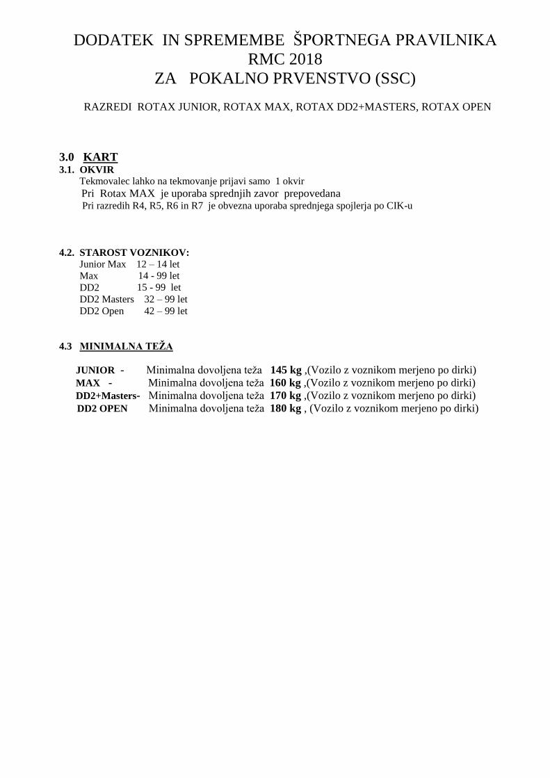
The profile of the combustion chamber insert has to be checked with a template (ROTAX part no. 277 390). The crack of light between the template and the profile of the combustion chamber insert has to be the same over the whole profile.
5.3. Piston with ring assembly Original, coated, aluminum, cast piston with one piston ring. The piston has to show on the inside the cast wording "ELKO" (1) and "MADE IN AUSTRIA" (2). Machined areas are: Top end of piston, outside diameter, groove for the piston ring, bore for the piston pin, inside diameter at bottom end of piston and some pre-existing factory removal (3) of flashing at the cut out of the piston skirt. All other surfaces are not machined and have cast surface. Any mechanical treatment or rework of the piston is forbidden, (e.g. removal of carbon deposits). Cleaning without changing the original surface is allowed. Original, magnetic, rectangular piston ring. Ring height : 0,98 +/- 0,02 mm. Piston ring is marked either with "ROTAX 215 547" or "ROTAX 215 548". The piston ring is legal also if just parts of the marking are still visible.
5.4. Piston pin Piston pin is made out of magnetic steel. Dimensions must be according to the drawing. The minimum weight of the piston pin must not be lower than 31,00 grams.
5.5. Cylinder Light-alloy-cylinder with GILNISIL-plating. Any re-plating of cylinder is not allowed. Maximum bore of cylinder = 54,035 mm (measured 10 mm above the exhaust port). Cylinder has to be marked with the "ROTAX" logo (see pictures below). 125 Junior MAX Cylinder with one main exhaust port and without exhaust valve. Cylinders marked with identification code 223 994 only are legal to be used. 125 MAX Cylinder with one main exhaust port and exhaust valve. Cylinders marked (cast or machined) with identification code 223 993 only are legal to be used.

RMC Technical Regulations 201
125 MAX DD2 Cylinder with one main exhaust portexhaust valve. Cylinder has to be marked with Height of cylinder (measured with a digital caliper125 Junior MAX and 125 MAX:125 MAX DD2: Cylinder surfaces All transfer ports and passages have cast finish surface except some removal (done by the manufacturer) of cast burr at the inlet passage, exhaust port and passages. All ports have chamfered edges to prevent ring snagging. Any additional machining is not permitted. The top edge of exhaust port may show some premachining from the manufacturer. The sealing flange for the exhaust socket may show signs of machining from the manufacturer. All ports have chamfered edges. Any additional machining is not permitted. Cylinders marked 223 993, 223 994of the central boost port may show factory machining. The flange for the exhaust socket may show either cast machined surface. Machined surface can be either flat or show a circular sealing bump.
RMC Technical Regulations 2018 Edition: 2017 10 17
one main exhaust port and two side exhaust ports and
with identification code 613 933.
(measured with a digital caliper min. length 200 mm). 125 Junior MAX and 125 MAX: 87,00 mm -0,05/+0,1 mm
86,70 mm -0,05/+0,1 mm
All transfer ports and passages have cast finish surface except some removal (done by the manufacturer) of cast burr at the inlet passage, exhaust port and passages. All ports have chamfered edges to prevent ring snagging. Any additional
The top edge of exhaust port may show some pre-existing machining from the manufacturer. The sealing flange for the exhaust socket may show signs of machining from the
All ports have chamfered edges. not permitted.
223 994 and 613 933 the upper edge of the central boost port may show factory machining.
The flange for the exhaust socket may show either cast finish or
either flat or show a circular sealing
Page 7 of 25

RMC Technical Regulations 2018 Edition: 2017 10 17 Page 8 of 25
The top edge of the exhaust port may show either just a cast finish surface (left picture) or signs of a CNC machining (central picture) or signs of CNC machining in combination with signs of manual grinding (right picture).
The exhaust port may show partial manual grinding done by the manufacturer to eliminate minor casting defects and/or to eliminate the NIKASIL burr at the end of the NIKASIL plating (right picture). Cylinders marked 223 994 and 223 993 and showing a cast letter mark (e.g. “J”) in the inlet port show a fully CNC machined exhaust port and a fully CNC machined top edge of the central boost port. The horizontal and vertical dimensions of the exhaust port (cylinder 223 994 with fully CNC machined exhaust port only) have to be checked with the template (Rotax part no. 676 240). The horizontal and vertical dimensions of the exhaust port (cylinder 223 993 with fully CNC machined exhaust port only) have to be checked with the template (Rotax part no. 676 245). The template has to be moved in horizontal- and vertical position as far as possible into the exhaust port. In both directions the template may not touch the exhaust socket flange.
Exhaust port timing The "exhaust port timing" (distance from the top of the cylinder to the top of the exhaust port) has to be checked by means of the template (ROTAX part no. 277 402). Insert the template (take care to use the correct gauge JUNIOR, MAX or DD2) into the cylinder, and move the template (at the highest point of the exhaust port) as far as possible into the exhaust port. In this position the template may not touch the cylinder wall.

RMC Technical Regulations 201
Exhaust valve (125 MAX and 125 MAX DD2If the piston is moved in direction top of cylinder and first timecovering completely the exhaust port, it must be possible to inserthe exhaust valve gauge (Rotaxthe surface of the cylinder (a feeler gauge of 0,05 mm must notbe possible to fit in at any area around).Modifying the gasket (Rotax part no. 250 231) between thecylinder and the exhaust valve housing
5.6. Inlet system Inlet manifold is marked with the identification code“267 915” and the name “ROTAX”valid for 125 Junior MAX and 125 MAX“267 410” and the name “ROTAX”valid for 125 MAX DD2. Some factory flash removal may be present at the conjunction of theinside contour and the carburetor stop mounting face. This is a manual trimming operation consisting of a small corner break of less than 3 mmin width. No additional grinding or machining is permitted.
The reed valve assy. is equipped with 2 petal stops and 2 reeds, each having 3 petals.The thickness of the reeds is 0,6 mm +/
5.7. Crankshaft Stroke 54,5 mm +/-0,1 mm Con rod has to show forged numbers "213", "365",“362” on shaft. Shafts of con rods "213", "365" andand are copper plated. Shaft of con rod “362” is not copper plated and(grey/brown). Grinding or polishing of shaft of con rod is not permitted.
Ignition signal on crankshaft: Fit the template (Rotax 277391) on the crankshaft.Align the hole in the template for the big end pin with the big endpin of the crankshaft. The two edges of the signal machining on the crankshaft must bein line (+/-0,5 mm) with the corresponding edges (MAX or DD2of the template.
RMC Technical Regulations 2018 Edition: 2017 10 17
and 125 MAX DD2) moved in direction top of cylinder and first time
covering completely the exhaust port, it must be possible to insert the exhaust valve gauge (Rotax part no. 277 030) until it stops at the surface of the cylinder (a feeler gauge of 0,05 mm must not be possible to fit in at any area around).
(Rotax part no. 250 231) between the cylinder and the exhaust valve housing is illegal.
Inlet manifold is marked with the identification code and the name “ROTAX” or just “267 916”,
125 Junior MAX and 125 MAX ” and the name “ROTAX” or just “267 411”,
val may be present at the conjunction of the inside contour and the carburetor stop mounting face. This is a manual trimming operation consisting of a small corner break of less than 3 mm in width. No additional grinding or machining is permitted.
ed valve assy. is equipped with 2 petal stops and 2 reeds, each having 3 petals.The thickness of the reeds is 0,6 mm +/- 0,10 mm.
w forged numbers "213", "365", "367" or
s "213", "365" and "367" are not machined
Shaft of con rod “362” is not copper plated and is blank
polishing of shaft of con rod is not permitted.
mplate (Rotax 277391) on the crankshaft.
Align the hole in the template for the big end pin with the big end
The two edges of the signal machining on the crankshaft must be 0,5 mm) with the corresponding edges (MAX or DD2)
Page 9 of 25
ed valve assy. is equipped with 2 petal stops and 2 reeds, each having 3 petals.

RMC Technical Regulations 2018 Edition: 2017 10 17 Page 10 of 25
5.8. Crankshaft main bearings Crankshaft main bearing 6206 from FAG is allowed only. (must be marked with code 579165BA or Z-579165.11.KL)
5.9. Balance shaft (125 Junior MAX and 125 MAX) Balance shaft and balance gears must be installed. Configurations of part no. 237 949 (equal with 237 948) only is legal. Surface (1) is not machined and must show cast surface. Measurement from center of balance shaft to outer diameter of fly weight of balance shaft at defined length must not be lower than specified. The minimum weigh of the dry balance shaft must not be lower than: 255 grams for balance shaft ROTAX part no. 237 949 (equal with 237 948).
5.10. 2-speed gearbox (125 MAX DD2) Primary shaft with 19 teeth for 1st gear and 24 teeth for 2nd gear. Idle gear for 1st gear has to have 81 teeth. Idle gear for 2nd gear has to have 77 teeth
5.11. Crankcase As supplied by the manufacturer. No grinding/polishing is permitted in the two main transfer passages as well as in the crank area. Uncoated as well as black coated crankcases are legal to be used.

RMC Technical Regulations 2018 Edition: 2017 10 17 Page 11 of 25
6. Technical Specification (outside the engine seal) for ROTAX kart engines 125 Junior MAX/evo 125 MAX/evo 125 MAX DD2/evo It is the responsibility of the competitor to check his equipment (all components outside the engine seal as mentioned below), to assure that his equipment is conforming to the technical specification below!
6.1. Balance drive (125 Junior MAX and 125 MAX) Steel balance gears only (minimum width = 8,8 mm) are legal to be used. Balance gears must be installed and must be aligned according to the instruction in the repair manual. Balance drive (125 MAX DD2) Balance drive gear must be fitted on crank shaft. Balance gear must be fitted on primary shaft and must be aligned with the balance drive gear according to the instruction in the repair manual. Version 1: Fly weight of balance gear must show cast surface Version 2: Fly weight of balance gear can show machined surface. Dimension A (widest part of balance weight) must be either 53,0 mm +/- 0,5 or 57,0 mm +/- 0,5 The minimum weight of a dry balance gear including bearing must not be lower than 240 grams.
6.2. Centrifugal clutch 125 Junior MAX and 125 MAX Engagement speed of centrifugal clutch at maximum 4.000 rpm (the kart without driver must start to move). Two versions of clutch (item 1, with and without holes) are legal to be used. Both versions are marked with the wording “ROTAX”. O-ring (item 2) must be fitted and must assure an appropriate sealing between the clutch drum and the needle/plain bearing. Two versions of clutch drum (item 3) are legal to be used. Both versions are marked with the wording “ROTAX”. Signs of emission of grease from the needle/plain bearing into the clutch drum may not exceed the picture beside. Contact area between clutch and clutch drum has to be dry at any time – no lubrication allowed.

RMC Technical Regulations 2018 Edition: 2017 10 17 Page 12 of 25
125 MAX DD2 Engagement speed of centrifugal clutch at maximum 4.000 rpm (the kart without driver must start to move). Both versions of clutch (item 6, with and without holes) are legal to be used. O-ring (item 11) must be fitted.
Height of clutch 125 Junior MAX and 125 MAX: Minimum = 11,45 mm 125 MAX DD2: Minimum = 14,45 mm
Thickness of clutch shoe Minimum = 24,10 mm Measurement has to be done at the 3 open ends of the clutch,. 5 - 10 mm from the machined groove (all clutch shoes must be completely closed at measurement - no gap).
Outer diameter of clutch drum Minimum = 89,50 mm Diameter has to be measured with a sliding caliper just beside the radius from the shoulder (not at the open end of the clutch drum).
Inner diameter of clutch drum Maximum = 84,90 mm The inner diameter has to be measured with a sliding caliper. The measurement has to be done in the middle of the clutch drum (in the contact area between clutch and clutch drum).

RMC Technical Regulations 2018 Edition: 2017 10 17 Page 13 of 25
Height of clutch drum with sprocket/primary gear 125 Junior MAX and 125 MAX Minimum = 33,90 mm 125 MAX DD2 Minimum = 39,50 mm
6.3. Primary drive (125 MAX DD2): Original primary drive gears of following gear ratio options must be used only. Following combinations are legal to be used. Drive gear Driven gear 32 65 33 64 34 63 35 62 36 61 37 60 38 59 A specific primary gear ratio may be determined for each race event by a “Bulletin”.
6.4. Gear shifting (125 MAX DD2) The 2-speed gearbox has to be operated from the steering wheel via two bowden cables. Aluminum shift paddles Cutting of the original aluminum shift paddles or adding of non original parts is not allowed. Mounting the shift paddles (item 31) on the bottom or top side of the whip (item 25) is an allowed adjustment. Optional parts (items 36-38) can be mounted on the shift paddle (item 31) in any position. Bending the aluminum shift paddles to align them to the steering wheel is an allowed adjustment.

RMC Technical Regulations 2018 Edition: 2017 10 17 Page 14 of 25
6.5. Combination of ignition system, carburetor and exhaust system The combination of components is limited to following specification per engine type. Components \ Engine type 125 Junior MAX 125 MAX 125 MAX DD2Ignition system Dell'orto ü ü üExhaust valve, electronic timed ü üCarburetor XS ü ü üExhaust system, evo ü ü ü
6.6. Exhaust valve (125 MAX and 125 MAX DD2)
Electronic timed system must be used only. System has to be used with all components fitted as shown in the illustration below. Green colored exhaust bellow (item 10) is legal to be used only. Length of the exhaust valve (item 2): 36,5 mm +0,20 mm/-0,30 mm. Width of collar: 4,8 mm +/-0,3 mm Fitting an original impulse nozzle � into the pressure hose is an allowed adjustment. The direction of the impulse nozzle inside the pressure hose is free.

RMC Technical Regulations 2018 Edition: 2017 10 17 Page 15 of 25
6.7. Ignition system Digital battery ignition system, variable ignition timing, no adjustments possible. Spark plug: NGK GR9DI Electrode gap (maxiumum): Filler gauge 1,00 mm must not fit in between the two electrodes.
Two versions of spark plug caps are legal to be used. Version 1: Black, marked with "NGK TB05EMA". Version 2: Red, marked “NGK” (see picture) The marking of the pick-up must show the following numbers in the first line 029600-0710. A steel ball (diameter 3-5 mm) placed on circular surface of the sensor must stay in the center of the circular surface. Mounting the pick up to the crankcase with a gasket additional to the original rubber sealing ring of the pick-up, is a legal specification. Additional gasket, Rotax 431 500, gasket thickness = 0,8 mm Maximum two gaskets (Rotax 431 500) are allowed to be fitted. Fitting position of the additional gasket(s): Crankcase – rubber sealing ring – additional gasket(s) – pick-up. Dellorto ignition system is legal to be used only. Race officials may request at any time that the competitor replaces the electronic box (ECU) with another unit provided by the race administration. Ignition coil (same for all engines) with separate electronic box (ECU, specific for every engine). Ignition coil and ECU (and magnet valve, for 125 MAX and 125 MAX DD2 only) have to be fitted with all components according to the illustrations below. In case the mounting bracket (125 Junior MAX and 125 MAX only) is in conflict with a chassis component, the additions of 2 spacers, one per mounting hole, with a maximum thickness of 20 mm between the mounting bracket and the gearbox cover is allowed. Two different mounting versions (left illustration and right illustration) are legal.

RMC Technical Regulations 2018 Edition: 2017 10 17 Page 16 of 25
125 Junior MAX and 125 MAX
125 MAX DD2
At the mounting versions as shown in the left illustrations, the ground cable of the cable harness has to be connected to the lower rubber buffer of the support plate. Removing the black coating of the gearbox cover (125 Junior MAX and 125 MAX) in specific areas defined by Rotax (for mass connection between cable harness and engine) is a legal modification. The visual appearance of the ignition coil must be identical with the pictures. Ignition coil must show 2 pins at the terminal. The ignition coil is labeled with two stickers, “BRP 666820” and “NIG 0105”. The ignition coil is still legal to be used also if one or both stickers disappeared. Minimum length of the high tension cable of the ignition coil is 210 mm (from outlet of ignition coil to outlet of spark plug connector = visible length of cable.

RMC Technical Regulations 2018 Edition: 2017 10 17 Page 17 of 25
The electronic control unit (ECU) is labeled with stickers and is still legal also if the sticker is unreadable or disappeared. 125 Junior MAX: “666813” 125 MAX: “666815” 125 MAX DD2: “666816” The ECU has to be checked with the ECU tester (Rotax part no. 276 230) according to following procedure. Disconnect engine cable harness from ECU. Connect ECU tester cable harness to ECU. Connect energy cable of ECU tester cable harness with the charging connector of engine cable harness. At every connection with the battery the software version of the ECU tester will be indicated on the display for approx. 2 seconds. The software version indicated on the display has to be 2V00. Start the test by pressing the button “ü” on the ECU tester. After approx. 3 second the type of ECU � that is actually tested will be indicated in the second line of the display. After approx. 30 seconds the result � of the test will be indicated in the first line of the display.
The ECU tester has to indicate following results: 125 Junior MAX category � 666813JNRMAX � !! Test OK !! 125 MAX category � 666815MAX � !! Test OK !! 125 MAX DD2 category � 666816MAXDD2 � !! Test OK !!
6.8. Battery, battery fixation Original batteries with following specification only are legal to be used. YUASA YT7B-BS (with and without Rotax branding) ROTAX RX7-12B or RX7-12L (lithium iron phosphate type) Battery must be fitted with the original battery clamp and battery cover (according to illustration below) and must be fixed to the chassis with both clamps (all 4 screws). Battery clamp must be mounted on the left side of the seat.

RMC Technical Regulations 2018 Edition: 2017 10 17 Page 18 of 25
6.9. Intake silencer 125 Junior MAX and 125 MAX Intake silencer with integrated, washable air filter has to be used with all parts as shown at the illustration and has to be mounted on the support bracket with two screws (in dry and wet condition).
Intake silencer tube (pos 2) and carburetor socket (pos 6) are marked with the wording "ROTAX". Intake silencer case bottom is marked on the inside with the Rotax part no. 225 015. Intake silencer case, top is marked on the inside with the Rotax part no. 225 025.
Three versions of original air filters (pos.4) are legal to be used. Single layer air filter (black), double layer air filter (green/orange), double layer air filter (green/darkgreen) marked “TwinAir”. Depending on the degree of oil-lubrication colours may alter slightly or the surface becomes stained (see examples).
Air filter (pos 4) must be installed as shown in the illustration between the two holders (pos 3) and must cover the complete area of the intake silencer case bottom (pos1).
Also at wet condition it is not allowed to attach anything to the air box to protect the air inlet from water spray.
125 MAX DD2 Intake silencer with integrated washable air filter as shown in illustration. The intake silencer case (pos 1) is marked on the inside with the Rotax part no. 225 012 (4 clips) or 225 013 (5 clips). The intake silencer cover (pos 2) is marked on the inside with the Rotax part no. 225 022 (4 clips) or 225 023 (5 clips). Two versions of air filters (pos 3) are legal to be used. Version 1, with integrated steel frame. Version 2, with separate plastic frame (pos 4). The air filter must be assembled between the intake silencer case and the intake silencer cover that the whole area of the intake silencer case is covered. At intake silencer cover (pos. 2, Rotax part no. 225 022), it is mandatory to fit the O-ring (pos. 6) on the intake silencer tube (pos. 5). Sealing the top of the intake silencer using adhesive tape is an allowed modification. Also at wet condition it is not allowed to attach anything to the air box to protect the air inlet from water spray.

RMC Technical Regulations 2018 Edition: 2017 10 17 Page 19 of 25
6.10. Carburetor Dellorto carburetor, housing has to show the cast wording “VHSB 34” Carburetor housing is stamped with “XS”. The complete inlet bore of the carburetor must show cast surface. Optional carburetor plug screw marked "ROTAX" (ROTAX part no. 261 030) is legal to be used. The two vent fittings must be connected with the original air vent hose min 155 mm (Rotax part no. 260 260). The location of the opening has to be placed at the rear side of the carburetor Settings of the carburetor adjustment screws (idle and idle air) are free. The position of the jet needle is free. All jets must be correctly seated and securely fitted at any time (tightened)! A minimum required size of main jet may be determined for each race event by a “Bulletin”. The height of the two arms of the float lever must be within the slot of the carburetor gauge (Rotax part no. 277 400) by their normal weight measured at carburetor housing without gasket in reverse upright position. Needle valve assembly stamped "150" Needle of needle valve marked with diamond symbol ”INC" only. Start jet is stamped with the digits “60”. Any Dellorto main jet number even if not offered from Rotax is legal to be used. Specific regulation for Dellorto VHSB 34 XS Carburetor slide shows digits “45” in casting. Jet needle must be stamped with “K57”. Two floats marked "4,0 gr" are legal to be used only Needle jet Stamped with ”DP267” Total length: 51,0 +/- 0,5 mm Length of bottom section: 33,0 +/- 0,45 mm Top bore diameter 2,67 +/- 0,10 mm
RMC Technical Regulations 2018 Edition: 2017 10 17 Page 20 of 25
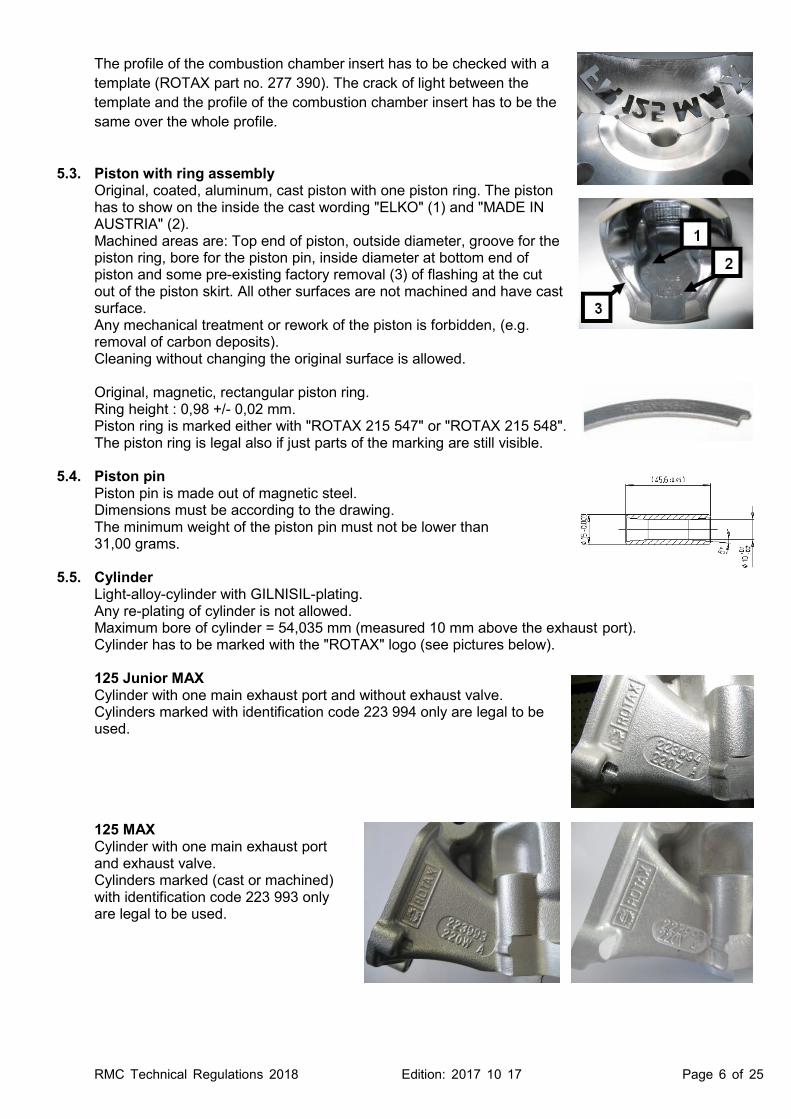
Idle jet Idle jet has to be stamped with 60. Plug gauge 0,65 mm may not enter the bore (use jet gauge set Rotax part no. 281 920).
Idle emulsion tube Idle emulsion tube has to be stamped with 45. Plug gauge 0,50 may not enter the central bore. (use jet gauge set Rotax part no. 281 920)
Atomizer Remove atomizer from carburetor body by means of venturi tool set (Rotax part no. 676 034); Atomizer, total length: 23,75 +/- 0.35 mm
Atomizer, length of cylindrical part: 15,75 +/- 0,25 mm
Atomizer, dimension of cutaway: 5,8 +/- 0,3 mm
Atomizer, dimension of cross bore: 5,0 +/- 0,15 mm
RMC Technical Regulations 2018 Edition: 2017 10 17 Page 21 of 25
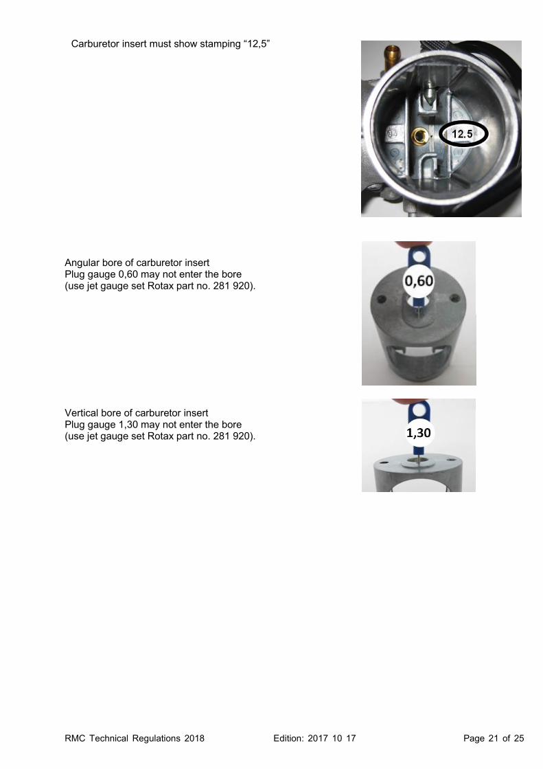
Carburetor insert must show stamping “12,5”
Angular bore of carburetor insert Plug gauge 0,60 may not enter the bore (use jet gauge set Rotax part no. 281 920). Vertical bore of carburetor insert Plug gauge 1,30 may not enter the bore (use jet gauge set Rotax part no. 281 920).

RMC Technical Regulations 201
6.11. Fuel pump, fuel filter MIKUNI diaphragm pump, (see picture) mounted as shown in the illustration. 125 Junior MAX and 125 MAXFuel pump must be mounted on the bottom side of the support bracket for the intake silencer 125 MAX DD2 Fuel pump must be mounted on the support bracket651 055, attached to the clutch cover (right illustration). Mounting the fuel pump with the two original rubber buffers to the chassis is an allowed option. In this case the fuel pump must be mounted below the inlet center line of the carburetor. Fuel filter Two versions of original fuel filter are legal to be used (see pictures) Except the fuel line, the fuel pump and the original fuel filter no additional parts are legal to be mounted between fuel tank and carburet
6.12. Radiator The removal of the thermostat from the cylinder head coveRadiator must be mounted with all components as shown in the To apply tape (neutral tape without advertising only)control the air flow through the radiator.Tape may not be removed from the radiator during operation on the track. Any other non original device to control the 125 Junior MAX and 125 MAXThe radiator has to be mounted on the right side of the engine.Three different versions as shown in the illustrations are legal to be used. Version 1 (legal to be used until December 31, 2017)Cooling area: Height = Thickness of radiator: 32 mm
RMC Technical Regulations 2018 Edition: 2017 10 17
(see picture) must be used and must be as shown in the illustration.
125 Junior MAX and 125 MAX Fuel pump must be mounted on the bottom side of the support
(left illustration).
on the support bracket, marked attached to the clutch
the two original rubber buffers
pump must be mounted below
are legal to be used (see
legal to be mounted between fuel tank and carburetor.
The removal of the thermostat from the cylinder head cover is an allowed modificationRadiator must be mounted with all components as shown in the respective To apply tape (neutral tape without advertising only) around the radiator is
flow through the radiator. Tape may not be removed from the radiator during operation on the track.
non original device to control the air flow through the radiator is
MAX and 125 MAX The radiator has to be mounted on the right side of the engine. Three different versions as shown in the illustrations are legal to be used.
(legal to be used until December 31, 2017) Height = 290 mm, width = 133 mm 32 mm
Page 22 of 25
r is an allowed modification. respective illustration.
iator is an allowed modification to
Tape may not be removed from the radiator during operation on the track. prohibited.

RMC Technical Regulations 2018 Edition: 2017 10 17 Page 23 of 25
Version 2 (legal to be used until December 31, 2017) Cooling area: Height = 290 mm, width = 133 mm Thickness of radiator: 32 mm The support plate (pos. 7) enables two different mounting positions (height) of the radiator. Both mounting positions are legal to be used. Version 3 Cooling area: Height = 290 mm, width = 138 mm Thickness of radiator: 34 mm Radiator must be stamped on the side with the wording “ROTAX”. To remove the original flap is an allowed modification. 125 MAX DD2 The radiator has to be mounted on the left side of the driver seat. The highest point of the radiator with cap may not be higher than 400 mm above the main tube of the kart chassis. Two different versions as shown in the illustrations are legal to be used. Version 1 (legal to be used until December 31, 2017) Cooling area: Height = 284 mm, width = 202 mm Thickness of radiator: 32 mm Version 2 Cooling area: Height = 290 mm, width = 196 mm Thickness of radiator: 34 mm To remove the original flap is an allowed modification.

RMC Technical Regulations 2018 Edition: 2017 10 17 Page 24 of 25
6.13. Engine coolant Plain water without any additives has to be used.
6.14. Exhaust system The measurement (C) must be at least 15,5 mm.
The use of maximum 4 pieces of original Rotax exhaust springs, to fix the exhaust system to the cylinder is allowed. (a “safety wire” in the exhaust flange area is not allowed).
Original exhaust system as supplied by Rotax is mandatory to be used. Welding at the exhaust system is only allowed in the case of a repair. Allowed modifications on the original exhaust systems are: ► Replacing the original rivets of the silencer end cap by 4 mm metricscrews and corresponding locking nuts. ► Replacing the isolating mat (just one original isolating mat may befitted) inside the silencer and the silencer end cap with perforated tube by original Rotax spares parts. ► Welding a socket (in a distance of 50-80 mm from the ball joint) on the top of the exhaust system formeasuring the exhaust gas temperature. ► Addition extra elements after the original silencer for further noise reduction.► Additional to the standard isolation mat a steel isolation mat(Rotax part no. 297 983) of the square dimension of 165 +10 mm is legal (not mandatory) to be assembled underneath the standard isolation mat according to the illustration. Clamp (1) must be fitted at a distance of 18+/-2mm, measured from the end of the tube. Clamp (2) must be fitted at the end area of the steel isolation mat. The measurement 10-12 mm from the end of the perforated tube to the beginning of the steel isolating mat is a specification for assembly purpose only! Both clamps (1 and 2) are mandatory to be fitted and tightened.
125 Junior MAX and 125 MAX Tuned pipe with 180° elbow and silencer are two separate pieces. The silencer is fixed with 2 springs to the 180° elbow and two springs to the tuned pipe. To fit a 3rd original spring (crosswise at the ball joint connection between 180° elbow and silencer) is an allowed option. The silencer has to be mounted in a position where the direction of the 90° elbow outlet (direction of the hot exhaust gasses) does not harm any component of the chassis. The original design silencer end cap with 90° elbow is mandatory to be used.
Dimensions to be checked are: Length of inlet cone: 590 mm +/-5 mm Length of cylindrical part of exhaust pipe: 130 mm +/-5 mm Length of end cone: 230 mm +/-5 mm

RMC Technical Regulations 2018 Edition: 2017 10 17 Page 25 of 25
125 MAX DD2 Tuned pipe with 180° elbow and silencer are two separate pieces. The silencer is fixed with 2 springs to the 180° elbow and two springs to the tuned pipe. The silencer can be turned that the 90° elbow outlet of the silencer shows either downwards towards the asphalt (preferred version for lowest noise emissions) or towards the back. The silencer has to be mounted in a position where the direction of the 90° elbow outlet (direction of the hot exhaust gasses) does not harm any component of the chassis. To fit a 3rd original spring (crosswise at the ball joint connection between 180° elbow and silencer) is an allowed option. The original design silencer end cap with 90° elbow is mandatory to be used.
Dimensions to be checked are: Length of inlet cone: 575 mm +/-5 mm Length of central part: 80 mm +/-5 mm Length of end cone: 240 mm +/-5 mm
6.15. Additional seat support (125 MAX DD2) On the engine side maximum one additional seat support is allowed to be used. The additional seat support must be fastened to the engine using the threaded hole designed for this purpose.


![Equivalent Number[DD2]](https://img.dokumen.tips/doc/110x75/577cde0c1a28ab9e78ae4775/equivalent-numberdd2.jpg)