Embed Size (px)
Citation preview
1
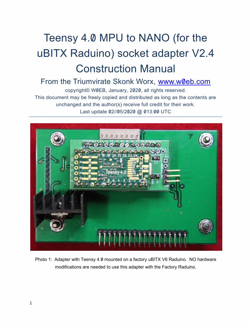
Teensy 4.0 MPU to NANO (for the
uBITX Raduino) socket adapter V2.4
Construction Manual From the Triumvirate Skonk Worx, www.w0eb.com
copyright© W0EB, January, 2020, all rights reserved.
This document may be freely copied and distributed as long as the contents are
unchanged and the author(s) receive full credit for their work.
Last update 02//05/2020 @ 013:00 UTC
Photo 1: Adapter with Teensy 4.0 mounted on a factory uBITX V6 Raduino. NO hardware
modifications are needed to use this adapter with the Factory Raduino.

2
Once you have your Teensy 4 adapter kit in hand, check the provided parts
against the BOM (Bill of Materials) at the end of this publication and contact
the TSW project coordinator (W0EB) by email at [email protected] if any are
missing. The two 14 pin MALE headers for mounting the Teensy 4.0 are
NOT provided with this kit and should be obtained at the same time you
purchase your Teensy 4.0 (unless you have them on hand already.)
1: Starting construction – If they aren’t already installed for you, first, install
the two .1 uF 0805 SMD chip capacitors at C1 and C2. Check your
soldering and make sure both ends are properly soldered to their terminals.
Photo 2: Capacitors in place
2: On the side of the board showing the Teensy V4 silkscreen, solder a
jumper wire between JP1 terminal B and the center terminal. (Once you
have identified the pads for the jumper, it does not matter which side of the
PC board you solder this jumper on.)
CAUTION! Pay close attention to the orientation here as it is CRITICAL to
proper operation.
3
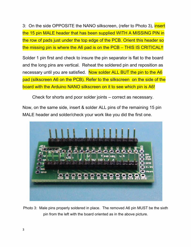
3: On the side OPPOSITE the NANO silkscreen, (refer to Photo 3), insert
the 15 pin MALE header that has been supplied WITH A MISSING PIN in
the row of pads just under the top edge of the PCB. Orient this header so
the missing pin is where the A6 pad is on the PCB – THIS IS CRITICAL!!
Solder 1 pin first and check to insure the pin separator is flat to the board
and the long pins are vertical. Reheat the soldered pin and reposition as
necessary until you are satisfied. Now solder ALL BUT the pin to the A6
pad (silkscreen A6 on the PCB). Refer to the silkscreen on the side of the
board with the Arduino NANO silkscreen on it to see which pin is A6!
Check for shorts and poor solder joints – correct as necessary.
Now, on the same side, insert & solder ALL pins of the remaining 15 pin
MALE header and solder/check your work like you did the first one.
Photo 3: Male pins properly soldered in place. The removed A6 pin MUST be the sixth
pin from the left with the board oriented as in the above picture.
4
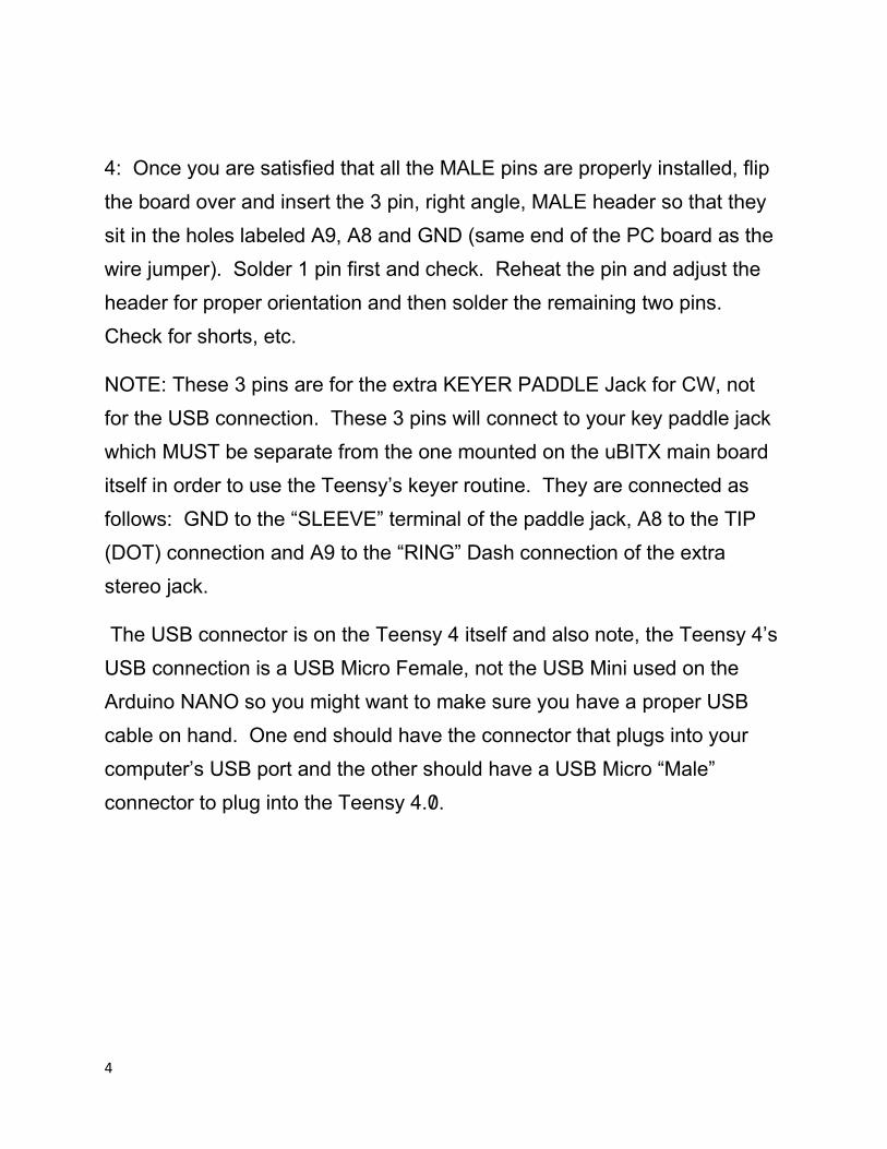
4: Once you are satisfied that all the MALE pins are properly installed, flip
the board over and insert the 3 pin, right angle, MALE header so that they
sit in the holes labeled A9, A8 and GND (same end of the PC board as the
wire jumper). Solder 1 pin first and check. Reheat the pin and adjust the
header for proper orientation and then solder the remaining two pins.
Check for shorts, etc.
NOTE: These 3 pins are for the extra KEYER PADDLE Jack for CW, not
for the USB connection. These 3 pins will connect to your key paddle jack
which MUST be separate from the one mounted on the uBITX main board
itself in order to use the Teensy’s keyer routine. They are connected as
follows: GND to the “SLEEVE” terminal of the paddle jack, A8 to the TIP
(DOT) connection and A9 to the “RING” Dash connection of the extra
stereo jack.
The USB connector is on the Teensy 4 itself and also note, the Teensy 4’s
USB connection is a USB Micro Female, not the USB Mini used on the
Arduino NANO so you might want to make sure you have a proper USB
cable on hand. One end should have the connector that plugs into your
computer’s USB port and the other should have a USB Micro “Male”
connector to plug into the Teensy 4.0.
5
Photo 4: Right angle header for A8, A9 & GND properly installed.
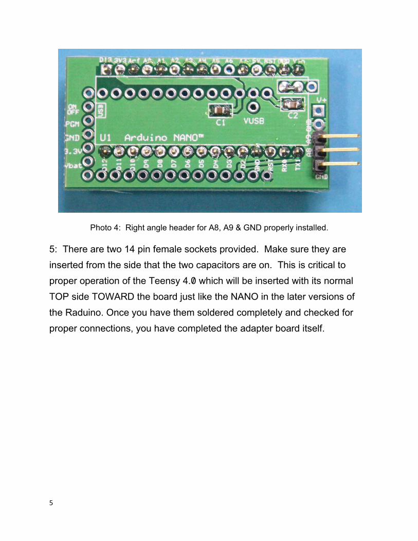
5: There are two 14 pin female sockets provided. Make sure they are
inserted from the side that the two capacitors are on. This is critical to
proper operation of the Teensy 4.0 which will be inserted with its normal
TOP side TOWARD the board just like the NANO in the later versions of
the Raduino. Once you have them soldered completely and checked for
proper connections, you have completed the adapter board itself.
6
Photo 5: Female (Teensy 4.0) socket installed. (Note orientation of board.)
6: Preparing your Teensy 4.0 for use with the adapter. (You need to order
your Teensy 4.0 with pins UNSOLDERED, or pick up two 14 pin male
headers as these are NOT included in the adapter kit.)
7: First insert the two 14 pin male headers for the teensy into the two long
female sockets with the short pins sticking up. This will help position them
and give you a more stable platform for soldering them to your Teensy 4.0.
8: Turn the Teensy 4.0 upside down and orient it so the Teensy’s USB
connector is on the side toward C2 and the jumper JP1. (There is also a set
of connection pads labeled V+, GND A9, A8 and another GND on that
same end you can use for further help in orienting the USB connector
properly.) Place the Teensy 4.0 over the pins so all pins fit through their
respective holes in the Teensy’s PCB and CAREFULLY solder/check all
pins. The 5 pins opposite the USB connector on the Teensy itself are not
used at this time. Also

7
Photo 6: Teensy 4.0 with pins properly soldered and oriented, plugged into the adapter.
Now, you can plug the adapter into the Raduino from the back just like you
would plug in a NANO but with USB connector toward your right. You may
have to bend the 7805 regulator down slightly if the heat sink doesn’t clear
the bottom of the adapter board, Just be careful when you bend it and it will
be OK.
If you are using the adapter with a uBITX radio, when you power up the
system, you should enter the Display Touch Calibration screen by holding
the encoder button in as you apply power. Follow the on screen
instructions to calibrate TOUCH or the touch screen may not work for you.

8
Photo 8: Completed Adapter with Teensy 4.0 on board plugged into a V6 Raduino.
Note the orientation of the Adapter board
Photo 9: Completed Adapter with Teensy 4.0 on board plugged into an older V5
Factory Raduino. Note the orientation of the adapter board.
NOTE: the 3 pin right angle MALE header is for the extra KEYER PADDLE
jack, not USB. USB connector is on the Teensy itself.

9
APPENDIX A: Bill of Materials Checklist:
CHECK QTY PART SOURCE
____ 1 PC Board [email protected]
____ 2 .1 uF 0805 SMD Cap. (C1, C2) Tayda A-942
____ 1 15 pin MALE header .1” spc Many different MFG
____ 1 15 pin MALE header with a missing
pin. See instructions for proper mounting.
_____ 1 3 pin MALE header .1” spc Many different MFG
_____ 2 14 pin FEMALE socket Tayda A1669 (15 pin)
carefully cut 1 pin off
NOTE: The two 14 pin MALE headers required for mounting the TEENSY
4.0 to the adapter board’s female sockets should be obtained at the same
time you obtain your Teensy 4.0 if you do not already have them on hand.
They should NOT be soldered to the Teensy until called for during the
construction of this adapter kit
If you purchased your uBITX with the case from the factory, you will also
need to obtain a different USB extension cable to match the MICRO “B”
connector for the Teensy as the MINI B extension cable provided with the
case will not mate with the newer style USB connector on the Teensy 4.0.

10
APPENDIX B: PCB Layout of the adapter.
11
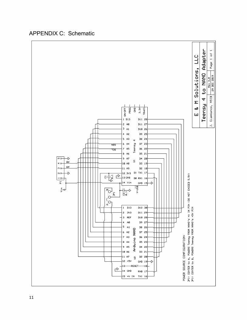
APPENDIX C: Schematic

12
Credits:
TSW (Triumvirate Skonk Worx)
Concept and software: Ron Pfeiffer, W2CTX
PCB design and layout Jim Giammanco, N5IB
Project Coordinator, documentation Author and kit supplier,
Jim Sheldon W0EB
See the TSW website www.w0eb.com for details and kit ordering
information.
Special thanks to Armando Assante, one of our first kit builders for
suggesting corrections and additions to this manual.
Manual last updated 02/ 05/2020 @ 013:00 UTC