Embed Size (px)
Citation preview

2009
Tectonic Studies Group Annual Meeting
Keele University, Keele, Staffordshire, UK.
5th - 8th January 2009
ProgrammeAbstract Volume
In association with:

TSG Annual Meeting 2009 Keele University, Staffordshire
Page 1
Tectonics Studies Group Annual Meeting 2009
Keele University, Staffordshire5 – 8 January 2009
Organisers Stu Clarke, Peter Styles & Graham Williams School of Earth Sciences & Geography, Keele University, Keele, Staffordshire, ST5 5BG
With special thanks to the following people:
Keele Facilities Management (KFM): Sam Rooney & Sharon Faulke
Website design and support: Sam Toon & Victoria Lane
Abstract volume & delegate packs: Michelle Stewart
…and many others who have helped out along the way.
Sponsors
With additional support from:

TSG Annual Meeting 2009 Keele University, Staffordshire
Page 2
Contents Programme................................................... Page 3 Presentation abstracts................................... Page 11 Poster abstracts............................................. Page 57 Fieldtrip information .................................... Page 83 Delegate list.................................................. Page 87 Maps and directions ..................................... Page 90

Tectonics Studies Group Annual Meeting 2009
Keele University, Staffordshire5 – 8 January 2009
Programme


TSG Annual Meeting 2009 Programme
Page 5
Monday 05 January 2009
Registration 16:00 – 19:00 Registration for all residential delegates at the Holiday Inn, J15 M6
19:30 onwards Welcome drinks reception followed by dinner
Tuesday 06 January 2009
Registration and Welcome 8:30 – 9:30 Registration for non-residential and day delegates at Keele University
9:30 – 9:45 Opening address by Professor Peter Jones, Pro-vice Chancellor (Research & Enterprise), Keele University
Session 1: Analogue and numerical structural modelling & mapping
9:45 – 10:00 Krabbendam, M., Goodenough, K., Jordan, C., Bee, E., Smith, N., Wildman, G., Marchant, A., Lawrie, K. & Adlam, K.
Digital mapping using the BGS SIGMA system
10:00 – 10:15 Fermandez-Lozano, J., Sokoutis, D., Willingshofer, E., De Vicente, G. & Cloetingh, S.
Mountain building and basin development on an intraplate area: Insights from analogue modelling in Iberia
10:15 – 10:30 Austin, L., Egan, S.S., Clarke, S.M. & Kirby, G.
The geological and geodynamic modelling of the Northumberland Trough and Alston Block, northern England: New insights from numerical modelling
Session 2: Shear zones
10:30 – 10:45 Leslie, A. G. & Campbell, S.D.G. Does the Glendoe TBM tunnel intersect the Grampian orogenic front SE of the Great Glen Fault?
10:45 – 11:00 Allen, M., Kheirkhah, M. & Emami, M. Right-lateral shear across Iran and kinematic change in the Arabia-Eurasia collision zone
11:00 – 11:15 Berwouts, I., Muchex, P. & Sintubin, M.
The North Armorican Shear Zone: fluid conduit or fluid barrier?
Coffee Break 11:15 – 11:45

TSG Annual Meeting 2009 Programme
Page 6
Session 3: Transpression, inversion & uplift
11:45 – 12:00 Thomas, C. & Woodcock, N. The southern segment of the Dent Fault, N England: flowers, thrusts, keels and the link with the Craven faults
12:00 – 12:15 Holford, S. P., Turner, J. P., Green, P. F. & Hillis, R. R.
The signature of cryptic sedimentary basin inversion revealed by shale compaction data in the Irish Sea, western British Isles
12:15 – 12:30 Kelly, J. E., & Turner, J. P. The post-Triassic uplift and erosion history of the SW UK: timing, magnitude and driving mechanisms
12:30 – 12:45 Walker, R. J., Holdsworth, R.E. & Imber, J.
Clastic shear-fabrics and intrastratal-flow in basalt provinces: Uplift-related fault classifications on the NE Atlantic Margin
12:45 – 13:00 Discussion & poster presentations
Lunch 13:00 – 14:00 Session 4: Palaeostress, strain, fissures & fractures 1
14:00 – 14:15 Kipata, M.L., Delvaux, D., Sebagenzi, M.N., Cailteux, J. J. & Sintubin, M.
Preliminary results of a palaeostress analysis in the Pan-african Lufilian Arc, Katanga, DRC
14:15 – 14:30 Boro, H., Bertotti, G., Hardebol, N., Luthi, S., Vaart, J. & Ewonde, K.
Observing fracture patterns and interpreting mechanical stratigraphy in layered rocks: Integrating GIS in fracture study
14:30 – 14:45 Woodcock, N., Wright, V. & Dickson, T.
Fissure fills along faults: Variscan examples from Gower, South Wales
14:45 – 15:00 Van Noten, K. & Sintubin, M. Spatial distribution of quartz veins in alternating siliciclastic sequences and its relationship to bed thickness
15:00 – 15:15 Discussion & poster presentations
Coffee Break 15:15 – 15:45 Session 5: Palaeostress, strain, fractures & fissures 2
15:45 – 16:00 Martin, J., Holdsworth, B., McCaffrey, K., Conway, A. & Clarke, S. M.
Fractures in the Lewisian Gneiss Complex of mainland Scotland: A valuable analogue for the offshore Clair Field basement?
16:00 – 16:15 Ellis, M. A., Hargrove, P. G. & Laubach, S.E. Fracture pattern development in the Applecross Fromation (Torridonian) sandstones south of Ullapool, NW Scotland

TSG Annual Meeting 2009 Programme
Page 7
16;15 – 16:30 Hargrove, P.G., Ellis, M.A., Laubach, S.E. Fault-related fracture pattern evolution and distribution in Cambrian Eriboll Formation sandstone: Northwest Highlands, Scotland
16:30 – 16:45 Faure Walker, J.P., Roberts, G.P., Sammonds, P.R., Cowie, P.
Comparison of earthquake strains over 102 and 104 year timescales: insights into variability in the seismic cycle in the central Apennines, Italy
16:45 – 17:45 TSG Annual General Meeting
Residential delegates’ dinner 20:00 Comus Restaurant Keele University

TSG Annual Meeting 2009 Programme
Page 8
Wednesday 07 January 2009
Registration and Welcome 8:30 – 9:30 Registration for non-residential and day delegates at Keele University
Session 1: Extensional structures & kinematics
9:30 – 9:45 Balsamo, F., Storti, F., Salvini, F., Silva, A. T. & Lima, C. C.
Extensional fault zone evolution in poorly lithified low porosity sandstones of the Barreiras Formation, NE Brazil: structural and petrophysical data
9:45 – 10:00 Long, J.J. & Imber, J. Analysis and significance of ductile deformation in the volume surrounding two seismically-imaged normal faults
10:00 – 10:15 Spendlove, S.J., Turner, J.P. Stevenson, C.T., Bond, C.E. & Similox-Tohon, D.
Geometry & kinematics of a extensional duplex in a compressional setting, Crackington Haven, SW England
10:15 – 10:30 Fodor, L. I. Fault-related folds, along-dip segmentation and reactivation of basement faults in SW Sirte Basin Libya
10:30 – 11:00 Discussion & poster presentations
Session 2: Folding & thrusting
11:45 – 12:00 Treagus, S. H. & Fletcher, R. Controls of folding on different scales in multilayered rocks
12:00 – 12:15 Lisle, R. & Toimil, N. Characterising fold patterns using hinge lines
12:15 – 12:30 McCabe, N. A. & Freeman, S. R. 3D structural styles in the outer portion of a deepwater fold and thrust belt; example from the deepwater Niger Delta
12:30 – 12:45 Iacopini, D., Grimaud, J.L. & Butler, R. W. H.
Structural analysis of fold and thrust structures from deepwater west Niger Delta.
12:45 – 13:00 Discussion & poster presentations
Lunch 13:00 – 14:00
Coffee Break 11:00 – 11:45

TSG Annual Meeting 2009 Programme
Page 9
Session 3: Regional Studies
14:00 – 14:15 Henderson, A.L., Najman, Y. Parrish, R.R., BouDagher-Fadel, M., Foster, G., Garzanti, E. & Ando, S.
Assessing the evidence for the timing of India-Asia collision from the Indus Group, Ladakh Himalaya
14:15 – 14:30 Rippington, S. & Scott, R. Ellesmerian and Caledonian deformation in North Greenland & Svalbard
14:30 – 14:45 Delvaux, D., Smets, B., Wauthier, C., Macheyeki, A. S., Sariah, E., d’Oreye, N., Oyen, A., Kervyn, F., Stamps, S. & Calais, E.
Surface structures related to the July 2007 Natron dyking event, N-Tanzania
14:45 – 15:00 Cunningham, D., Davies, S., McLean, D.
Exhumation of a Cretaceous rift complex within a late Cenozoic restraining bend, southern Mongolia: Implications for the crustal evolution of the Gobi Altai region
15:00 – 15:15 Mecklenburgh, J. & Rutter, E. Mid-lower crustal low viscosity channel beneath Tibet - the view from experimental rock mechanics
15:15 – 15:30 Discussion & poster presentations
Coffee Break 15:30 – 16:00 Session 4: Mass transport complexes and slumping
16:00 – 16:15 Butler, R. & McCaffrey, B. The structural geology of mass transport complexes
16;15 – 16:30 Debacker, T.N., Dumon, M. & Matthys, A.
Interpreting small complex datasets of slump features: examples from the lateral parts of a Middle Ordovician slump sheet within the Anglo-Brabant deformation belt (Belgium)
16:30 – 16:45 Richardson, S., Allen, M., Davies, R., McCaffrey, K. & Grant, S.
Mass-wasting in a record of uplift and climate change: the Absheron Suite, South Caspian Basin, Azerbaijan
16:45 – 17:00 Closing remarks Conference Dinner 19:30 Keele Hall Thursday 08 January 2009
Fieldtrip: The southern sector of the Dent Fault: Dentdale and Barbondale 8:30 Busses depart Keele University for Dentdale via the Holiday Inn J15
15:00 Busses depart Barbondale for Keele University (ETA 18:00)

TSG Annual Meeting 2009 Programme
Page 10
Posters Aanyu, K., Koehn, D., Passchier, C. & Sachau, T.
Modeling surface-structure development of the western arm of the Ears: reference area within longitudes 3°N and 5°S
Ashby, D., McCaffrey, K., Holdsworth, R., Almeida, J. & Boyd, K.
An onshore-offshore study of basement-influenced oblique tectonics in the South Atlantic passive margin
Austin, L., Egan, S.S., Clarke, S.M. & Kirby, G.
The influence of igneous intrusions on regional post-emplacement structural and geodynamic evolution: Insights from numerical modelling of the North Pennines Batholith, northern England.
Baudon, C., Fabuel-Perez, I, Van Den Driessche, J. & Redfern, J.
Structural evolution of Triassic basins and implications on the kinematics of the Atlantic rifting; insights from the Oukaimeden and Argana Valleys, Central and Western High Atlas of Morocco.
Blake, O. & Faulkner, D. Quantifying and comparing the evolution of dynamic and static elastic properties as crystalline rock approaches failure.
Debacker, T. N., Holdsworth, R.E. Influence of D1 fabric on the development of later structures within the Southern Uplands Terrane (U.K.)
Fermandez-Lozano, J., Sokoutis, D., Willingshofer, E., De Vicente, G. & Cloetingh, S.
Lithospheric-scale folding in Iberia from the perspective of analogue modelling
Green, S. & Rutter, E. High resolution monitoring of the Mam Tor landslip Haslam, R., Clarke, S.M., Styles, P. & Auton, C.
Structural modelling of possible contaminant pathways below nuclear installations
Holford, S.P., Green, P.F., Hillis, R.R., Duddy, I.R. Turner, J.P. & Stoker, M.S.
Regional uplift episodes along the NE Atlantic margin constrained by stratigraphic and thermochronologic data
Loveless, S., Bense, V. & Turner, J.
Faulting within Loosely Consolidated Deltaic Sediments and its Potential Impact on Fluid Migration Pathways
Maggi, M., Rossetti, M., Simeone, N., Tecce, F. & Vignaroli, G.
Fluid-rock interaction in an exhumed ductile-to-brittle shear zone: evidence for meteoric fluid infiltration at the depth of the brittle-ductile transition during the post-orogenic evolution of the Schistes Lustrés Nappe, Alpine Corsica (France).
Moy, D.J. & Imber, J. A three dimensional analysis of the geometry and kinematics of a transfer zone
Richardson, S., Allen, M., Jones, S., Davies, R., McCaffrey, K. & Grant, S..
Mass-wasting in a record of uplift and climate change: the Absheron Suite, South Caspian Basin, Azerbaijan
Sagi, D.A., De Paola, N., Faulkner, D.R. & Colletini, C.
The control of fracture patterns and connectivity on the evolution of low porosity anhydrite rocks
Sathar, S., Faulkner, D., Worden, R. & Smalley, C.
Experimental simulation of pressure solution in halite as an analogue for pressure solution in sandstones – Preliminary results
Spendlove, S.J., Stevenson, C.T., Turner, J.P. & Smith, M.P.
Embedding Enterprise into Geological Mapping
Storti, F. & Balsamo, F. Exploiting operating procedures in laser diffraction granulometry to investigate on the evolution of cataclastic fabrics in carbonate fault breccias.
Vetterlein, J. & Roberts, G.P. Structural Evolution of the Northern Cerberus Fossae graben system, Elysium Planitia, Mars
Walker, R.J., Holdsworth, R.E., Imber, J. & Ellis, D.
Structural precursors to continental break-up; the Faroe Islands, NE Atlantic Margin
Wilkinson, M., McCaffrey, K., Cowie, P., Roberts, G. & Phillips, R.
Strain accumulation at the lateral tips of active normal faults: a study of extensional deformation in the Apennines, Italy
Woodcock, N. & Mort, K. A revised classification of fault breccias

Tectonics Studies Group Annual Meeting 2009
Keele University, Staffordshire5 – 8 January 2009
Presentation Abstracts


TSG Annual Meeting 2009 Presentation Abstracts
Page 13
Tuesday 06 January 2009
Session 1: Analogue and numerical structural modelling & mapping
Digital mapping using the BGS SIGMA system
M Krabbendam1, K Goodenough1, Colm Jordan2, Emma Bee2, Nikki Smith1, Gerry Wildman2, Andy Marchant2, Ken Lawrie1 & Keith Adlam2
1British Geological Survey. Murchison House, Edinburgh EH9 3LA, UK 2British Geological Survey. Keyworth, Edinburgh EH9 3LA, UK Email: [email protected] The classic pre-digital way of geological mapping and map production typically consists of field mapping at the 1: 10,000 scale, production of hand drawn clean-copies (‘standards’) at the same scale in the office, followed by a generalization to 1:50,000 scale and cartographic production. Over the last decades, BGS has moved increasingly to digital procedures and products for these steps. Since 2006 these now cover the whole process, which is termed SIGMA (System for Integrated Geoscience Mapping). The three components comprise a digital field data capture system (SIGMA-Mobile), a desktop-based digital clean copy maker (SIGMA-Desktop) and a digital cartography system (SIGMA-Publisher). All these components are based on ArcMap, but each component has its own (heavy) customizations.
At the back of the system is a complex database, split into different geological/ cartographic features, e.g.. geological boundaries, faults, fold axial traces, foliation measurements. Each feature has a number of attributes. For instance, an entry in the feature ‘tectonic foliation’ can have as attributes the dip, dip direction and the type, for instance schistosity, in addition to XY information and other metadata. As with any GIS, features are either points (e.g. a structural measurement), lines (e.g. a geological boundary or a fault trace) or polygons (eg. an area with a particular lithology) The database covers all aspects that are captured on various BGS maps, including structure, lithology, worked ground, superficial deposits, geomorphological features, slope instabilities etc.
The greatest challenge, and the latest to develop, has been the digital field data capture system, SIGMA-Mobile. Reasonably light-weight, powerful and rugged tablet PCs with integrated GPS are now available and for this platform the SIGMA-Mobile customization has been created. Customization include a map-face and a ‘note-book face’, with possibility of making sketches just like in your paper notebook, a front-end to populate standardized databases, several sketch tools to draw the map or make comments and a tool for drawing structural contours. A live demonstration will be attempted to highlight some of the features.
As with any move to digital technology, there are advantages and disadvantages. Disadvantages include weight, cost, loss of flexibility, the idea of a ‘database strait-jacket’ to put your data in, and the usual frustrations of working with new software. Advantages include a more standardized data collection and the possibility to use many other datasets as underlays, such as Digital Terrane Models, orthorectified aerial photos and previous versions of geological maps. This makes the SIGMA-Mobile system especially useful for the purpose of map revision, very much the future for BGS. Whether it is an appropriate tool for teaching geological mapping, however, is an interesting discussion point. From mid-2009, SIGMA-Mobile software will be made available as an open-source release from the BGS Website.

TSG Annual Meeting 2009 Presentation Abstracts
Page 14
Tuesday 06 January 2009
Session 1: Analogue and numerical structural modelling & mapping
Mountain Building and Basin Development on an Intraplate Area: Insights from Analogue Modeling in Iberia.
J. Fernández-Lozano1,2, D. Sokoutis1, E. Willingshofer1,G. De Vicente2, S. Cloetingh1
1Faculty of Earth and Life Sciences, Vrije Universiteit, Amsterdam (The Netherlands). 2Departamento de Geodinámica Interna, Universidad Complutense de Madrid (Spain).
Inferences from analogue models support the idea that the primary response to large-scale shortening is lithospheric folding controlling the overall present-day landscape development in Iberia. This process was full active from the Eocene to the Late Oligocene-Lower Miocene during the Alpine Orogeny and could be enhance by the reactivation of inherit Variscan faults and mechanical discontinuities as previous instabilities enable folding. Lithospheric-scale folding is associated with the formation of narrow/wide mountain ranges initiated on top of the folds. These mountain ranges are represented by upper crustal pop-ups forming the main topographic reliefs. The spacing of thrust systems and basin shapes are linked to the wavelength of folding, which has been investigated through changing the convergence rates adopted for models Iberia-I and Iberia-II. We propose a classification of the resulting sedimentary basin based on their geometry and position. We identify two different kinds ofbasins regarding their spatial-temporal evolution: A) Small Intra-montain basins located within mountain ranges developed by pop-up and pop-down type features. B) Inter-montain basins which are wider appear in between main mountain ranges. Due to their different evolution we can distinguish among two different steps in the basin development: i) Basin formation and ii) basin deformation. The first stage involves the formation of sedimentary basins within and in between mountain ranges (intramontain to intermontain basins). Typically these mountain ranges are pop-up structures. During the second stage the basin get deformed by late thrusts, which sometimes do not reach the model surface (blind thrusts; see profiles I-III of models Iberia-I and Iberia-II). Different types of thrust faults can be indentified and their spacing, length and complexity are linked to main instabilities created at crust-mantle scale. Pop-up like structures are produced on top of thickened lower crust over first order folds and generates the main mountain ranges. Their spacing and width are controlled by folding enabled by mechanical decoupling between the different levels of the lithosphere. Consequently, the periodicity and wavelength of the topographic uplifts are the response of the different mechanical behaviour between the different layers that comprise the model lithosphere and that of Iberia. Thrusts with opposite vergences produce deformation of developed basins and blind thrusts may be the cause of small-scale uplifts within the basins. High convergence rate produces complex structures, giving rise to cross-cutting relationships between early pop-up structures and late thrust faults.

TSG Annual Meeting 2009 Presentation Abstracts
Page 15
Tuesday 06 January 2009
Session 1: Analogue and numerical structural modelling & mapping
The geological and geodynamic evolution of the Northumberland Trough and Alston Block, northern England: New insights from numerical modelling.
Linda Austin1, Stuart Egan1, Stuart Clarke1 & Gary Kirby2
1Earth Sciences and Geography, School of Physical and Geographical Sciences, Keele University, Keele, Staffordshire, ST5 5BG, United Kingdom. 2British Geological Survey, Kingsley Dunham Centre, Keyworth, Nottingham, NG12 5GG, United Kingdom.
The Northumberland Trough region, is a Carboniferous extensional system with a block and basin architecture. It includes the Northumberland Trough, its westerly continuation, the Solway Basin, the Alston Block, a geomorphological high situated to the south of the Northumberland Trough, the Vale of Eden Basin to the west of the Alston block, and the Stainmore Trough to the south of the Alston Block. The region has experienced a number of extensional, compressional and wrench tectonic events throughout late Palaeozoic, Mesozoic and Cenozoic times. These events have led to a complex subsidence-uplift history that cannot be adequately explained by theories of uniform lithosphere extension. In this work the geological and geodynamic processes that have controlled the evolution of the Northumberland Trough region in northern England are investigated in terms of a number of possible tectonic scenarios.
The analyses of surface and subsurface data combined with numerical modelling techniques have been used to examine the tectonic and stratigraphic development of the region. Model algorithms have been developed in two dimensions for the realistic simulation of the structural deformation caused by geological faulting (by vertical and inclined shear), thermal processes, the flexural isostatic response of the lithosphere due to tectonic loading and the buoyancy effects created by granitic intrusion into the crust. The stratigraphy varies across the region due to significant differences in depositional environment, particularly between the block and basins. This has been addressed within the modelling by the development of algorithms to simulate compaction and erosion, as well as lateral and temporal variations in the physical parameters related to the infilling sediment (e.g. density and porosity).
Models that reconcile the observed amount of fault-controlled deformation with the magnitude of overall thinning of the crust generate comparable amounts of subsidence to that observed in the basin structures. However, the amount of subsidence generated on the block structures by these initial models is too great. This may be due to the North Pennines Batholith, a non-porphyritic, per-aluminous granite, intruded towards the end of the Caledonian orogeny, approximately 410Ma, which acts as a negative load upon the lithosphere. The crust responds to this negative load by isostatic uplift, resulting in differential subsidence between the Alston Block and the surrounding basins.
Model results that have included algorithms to simulate the effect of the batholith generate decreased subsidence over the Alston Block that is equivalent to the amount observed in the available subsurface data, whilst maintaining the volume of accommodation space created in the basins. These results also highlight some of the limitations of using a two dimensional modelling approach including the limitations that faults are considered as two dimensional objects and it is not possible to consider variations in isostatic loading outside the plane of section. Further development of the modelling is taking place to produce a realistic three dimensional geodynamically constrained model of the Northumberland Trough region to provide an understanding of how regional interactions between structural, thermal, stratigraphic infill, bathymetric and isostatic processes have controlled the development of subsidence, and ultimately stratigraphy, within the basin system.

TSG Annual Meeting 2009 Presentation Abstracts
Page 16
Tuesday 06 January 2009
Session 2: Shear zones
Does the Glendoe TBM tunnel intersect the Grampian orogenic front SE of the Great Glen Fault?
Leslie, A.G. & Campbell, S.D.G.
British Geological Survey, Murchison House, Edinburgh, EH9 3LA. E-mail: [email protected] Scottish and Southern Energy’s Glendoe Hydro Scheme has driven a 4.6 m diameter smooth-bored TBM tunnel, SSE-ward 8.6 km from Fort Augustus and the Great Glen Fault (GGF) through mainly Grampian Group (Dalradian Supergroup) rocks deformed in the Grampian orogeny. This tunnel is, in effect, an 8 km long, gently-inclined continuous megaborehole, driven perpendicular to regional strike and thus providing unrivalled exposure of the geology - in this case through both footwall and hanging wall of the Eilrig Shear Zone (ESZ). The ESZ is unique in the Grampian Highlands terrane and is 1.5 km thick in the NW-end of the tunnel section. The shear zone is composed of quartz-muscovite (± biotite) mylonite, formed under low temperature ductile to brittle-ductile conditions. No such similar structure is recorded elsewhere in the Grampian Highlands terrane, where late-stage Grampian structures are generally represented by ductile folds and crenulation fabrics. In the ESZ hanging wall, the Grampian Group metasediments experienced typical NW-vergent Ordovician (Grampian) orogenic deformation accompanied by garnet-amphibolite facies metamorphism. In stark contrast, the footwall succession did not experience the pervasive orogenic deformation ubiquitous in the hanging wall and consists of fluviatile to shallow marine? deposits of uncertain stratigraphical age and correlation - the enigmatic Glen Buck Pebbly Psammite Formation. If Grampian (Ordovician) deformation is indeed absent in the footwall of the ESZ then that structure may assume considerable significance as fragment of the Grampian Orogenic Front, preserved SE of the GGF.
The net translation on this low temperature/high level shear zone seems likely to be considerable (100 km+?). At present the age of shearing is uncertain. Is the displacement late-Grampian (Ordovician) in age or Scandian (Silurian)? If the latter, what might be the relationship to the Moine Thrust Zone in the NW Highlands terrane across the GGF? Is the footwall succession to the ESZ comparable in any way to the ‘foreland’ succession in the NW Highlands?

TSG Annual Meeting 2009 Presentation Abstracts
Page 17
Tuesday 06 January 2009
Session 2: Shear zones
Right-lateral shear across Iran and kinematic change in the Arabia-Eurasia collision zone
Mark Allen1, Monireh Kheirkhah2 and Mohammad Emami2
1 Department of Earth Sciences, University of Durham, Durham, DL1 3LE 2 Geological Survey of Iran, Azadi Square, Meraj Avenue, Tehran, Iran A series of right-lateral strike-slip faults is present across Iran between 48° and 57° E. Fault strikes vary between NW-SE and NNW-SSE. Individual faults west of ~53° E were active in the late Tertiary, but have limited evidence of activity. Faults east of ~53° E are seismically active and/or have geomorphic evidence for Holocene slip. None of the faults affects the GPS-derived regional velocity field, indicating active slip rates are ≤2 mm/yr. We estimate overall slip on these faults from offset geological and geomorphic markers, based on observations from satellite imagery, digital topography, geology maps and our own fieldwork observations, and combine these results with published estimates for fault slip in the east of the study area. Total offset of the Takab, Soltanieh, Indes, Bid Hand, Qom, Kashan, Deh Shir, Anar, Daviran, Kuh Banan and Dehu faults is at least 270 km and possibly higher. Other faults (Zanjan, Rafsanjan) have unknown amounts of right-lateral slip. Collectively, these faults are inferred to have accommodated part of the Arabia-Eurasia convergence by two mechanisms: (1) anti-clockwise, vertical axis rotations; (2) strain partitioning with coeval NE-SW crustal thickening in the Turkish-Iranian plateau to produce ~350 km of north-south plate convergence. The strike-slip faulting across Iran requires along-strike lengthening of the deformation zone. This was possible until the Pliocene, when the Afghan crust collided with the western margin of the Indian plate, thereby sealing off a free face at the eastern side of the Arabia-Eurasia collision zone. Continuing Arabia-Eurasia plate convergence had to be accommodated in new ways and new areas, leading to the present pattern of faulting from eastern Iran to western Turkey.

TSG Annual Meeting 2009 Presentation Abstracts
Page 18
Tuesday 06 January 2009
Session 2: Shear zones
The North Armorican Shear Zone: fluid conduit or fluid barrier?
Isaac Berwouts, Philippe Muchez & Manuel Sintubin
Geodynamics & Geofluids Research Group, Department of Earth & Environmental Sciences, Katholieke Universiteit Leuven, Celestijnenlaan 200E, 3001 Leuven, Belgium
Shear zones throughout the world act as barriers or as conduits for fluids, which can have its implications on the regional fluid flow system. The aim of our research is to determine the fluid flow pattern along the North Armorican shear zone (NASZ; Brittany, France) between Landivisiau and Belle-isle-en-Terre (± 60 km).
The NASZ is one of the major (± 400 km long) shear zones crosscutting the Palaeozoic Armorican Massif in western Brittany. It forms the northern boundary of the Central Armorican Domain and is believed to have been active synchronous with the emplacement of the Plouaret-Commana granite (329 ± 9 Ma; Peucat et al., 1984), but it did not affect the microgranitic veins of Bas-Léon, which are dated at 292 ± 9 Ma (Chauris et al., 1977). An offset of 10 to 15 km along the shear zone is proposed by several authors and varies along strike. The core of the NASZ consists of grey quartz-rich ultramylonites or cataclasites with a thickness of only a few meters. The protolith in which the shear zone developed is composed of quartzites, metapelites and gneissified biotite-rich granites.
The structural context of the vein systems differs in the pelitic and igneous host-rock. Veins in pelitic rocks can be subdivided into veins perpendicular to quartzite layers (type 1), folded veins subparallel to bedding (type 2) and veins parallel to cleavage (type 3). Veins in the schists, gneisses and igneous rocks can be subdivided in pre- to syn-NASZ sheared veins (type 4) and post-NASZ veins that formed parallel to the foliation of the shear zone (type 5). The latter is sometimes associated with mineralizations of hematite, wolframite, pyrite or chalcopyrite.
The major constituent of the veins is quartz with occasionally minor amounts of chlorite or feruvite, a tourmaline variety. The quartz crystals show an undulose and patchy extinction, bulging recrystallisation and subgrain rotation recrystallisation. Most of the feldspars in the gneisses underwent brittle deformation in contrast to the mica and quartz crystals. All these properties indicate greenschist-facies metamorphic conditions, both during formation of the quartz veins as during activity of the NASZ. The outer western part of the shear zone is believed to be formed under higher metamorphic conditions (400 °C < T < 650 °C), because of the formation of stable biotite in shear bands and the formation of myrmekites (Goré & Le Corre, 1987).
No indications are present that the shear zone has affected the pelitic rocks or their associated quartz veins, while vein types in the igneous rocks and schists are clearly related to the NASZ activity. Vein type 4 is not as abundant as vein type 1 to 3 and vein type 5 formed within the foliation and thus after shearing. At this stage of research, there are no indications that fluids preferentially used the NASZ as fluid conduit during shearing. Stable isotopic and microthermometric studies will be performed on the different vein types to determine the P-T conditions during precipitation and the influence of the host-rock on the fluid chemistry and to further constrain the importance of the NASZ as fluid conduit.

TSG Annual Meeting 2009 Presentation Abstracts
Page 19
Tuesday 06 January 2009
Session 3: Transpression, inversion & uplift
The southern segment of the Dent Fault, N England: flowers, thrusts, keels and the link with the Craven faults.
Chris Thomas1 & Nigel Woodcock2
1 British Geological Survey, Murchison House, West Mains Road, Edinburgh, EH9 3LA 2 Department of Earth Sciences, University of Cambridge, Downing Street, Cambridge, CB2 3EQ
THE DENT FAULT is one of the iconic geological structures in the British Isles. First recognised by Dent’s famous son, Adam Sedgwick, for the most part it juxtaposes deformed lower Carboniferous strata on its eastern side against Lower Palaeozoic rocks to the west. The fault now defines the western margin of the Askrigg Block, but it is likely to be nucleated on a much older, block-bounding, crustal-scale structure.
The southern sector of the fault south from Dentdale has been remapped in the last few years by colleagues in the BGS and the University of Cambridge. The mapping reveals a complex structure with many of the features associated with transpressional fault systems, including positive flowers on the inside of compressional bends and extensional faulting on the elbows of releasing bends. The evidence for transpression is consistent with the structural history of the fault in the better-known area to the north of Dentdale. Folding and oblique-slip faulting in the footwall adjacent to the main fault strand persist along the length of the sector.
The southern-most sector of the fault and its termination is obscured by superficial deposits, but broadly, the fault runs into a complex zone where it meets with the Barbondale and Craven faults. Joint patterns and other features in Carboniferous strata indicate that these faults are closely related physically and temporally. For example, mapping on the N Craven Fault also indicates a transpressional element to its history.
In southern Barbondale, the Dent Fault is displaced sinistrally by c. 500m across a suite of faults in the ground between the two Lower Palaeozoic massifs of the Barbon and Middleton Fells. The displacement is interpreted to result, in a gross sense, from oblique-slip reverse faulting across the complex of faults. Our current working hypothesis is that this faulting itself results from a locking up of the southern tip of the Barbon Massif in the pinch between the Barbon and Dent Faults where they meet the N Craven Fault, forcing the break represented by the thrust further north in Barbondale. The thrust is therefore considered to be an integral part of the progressive transpressional deformation along the margin of the Askrigg Block during the Variscan.
Weather permitting, the post-conference fieldtrip to Barbondale will allow us to examine some of the outcrop- and landscape-scale features along the southern sector of the Dent Fault.
Dr Chris Thomas (BGS) will lead the TSG 2009 Fieldtrip to the southern sector of the Dent Fault
(Dentdale and Barbondale) on Thursday 8th of January 2009. Further details can be found on page 87

TSG Annual Meeting 2009 Presentation Abstracts
Page 20
Tuesday 06 January 2009
Session 3: Transpression, inversion & uplift
The signature of cryptic sedimentary basin inversion revealed by shale compaction data in the Irish Sea, western British Isles
Simon P. Holford1, Jonathan P. Turner2, Paul F. Green3 & Richard R. Hillis1
1Australian School of Petroleum, University of Adelaide, SA 5005, Australia ([email protected]) 2School of Geography, Earth & Environmental Sciences, University of Birmingham, B15 2TT, United Kingdom 3Geotrack International Pty Ltd, 37 Melville Road, West Brunswick, Victoria 3055, Australia Inversion is one of the most common modes of intraplate deformation and a primary mechanism of sedimentary basin exhumation. The key criterion for identification of basin inversion is the contractional reactivation of extensional faults. Since the reverse displacement associated with inversion is focussed along the upper segments of faults, evidence for inversion may be obliterated in deeply exhumed basins. We believe this is the case in the Irish Sea, western British Isles. The severe exhumation of this basin has been attributed to plume-related uplift, and inversion has been ruled out as a cause of uplift. We present a method for identifying tectonic inversion in a basin where exhumation has removed evidence of reverse displacement on the upper segments of faults. We utilize compaction-based mapping of erosion patterns recorded by anomalously high sonic velocities in Upper Triassic shales. We show that the amount of section removed during exhumation in the Irish Sea varies between 1.3-3.3 km and that exhumation patterns are markedly heterogeneous. Neither the heterogeneity of exhumation nor its focusing over hangingwall blocks of major faults is consistent with plume-related uplift and we believe that our results record cryptic basin inversion in a deeply exhumed basin. Erosion of reactivated fault segments is proposed as one of the major reasons that shortening is frequently underestimated in inverted basins. We examine other mechanical and rheological factors which hinder quantification of shortening in inverted and exhumed basins, and suggest that our method provides an efficient means of identifying basins affected by cryptic inversion.

TSG Annual Meeting 2009 Presentation Abstracts
Page 21
Tuesday 06 January 2009
Session 3: Transpression, inversion & uplift
The post-Triassic uplift and erosion history of the SW UK: timing, magnitude and driving mechanisms
John E. Kelly1,2 and Jonathan P. Turner1
1University of Birmingham, School of Geography, Earth and Environmental Sciences, Edgbaston, Birmingham B15 2TT, UK; 2Shell International Exploration and Production B.V, Kessler Park 1, 2288 GS Rijswijk, Netherlands. Recent work has demonstrated that the cratonic interiors of the passive continental margins which surround the North Atlantic region have been subject to widespread post-Triassic exhumation, the timing, magnitude and causes of which are debated. Using analysis of palaeothermal (apatite fission-track and vitrinite reflectance) seismic and compaction data, this study has revealed a multiphase uplift history with marked differences in exhumation over short horizontal distances (e.g. across individual faulted structures) across the Southwest UK. Regional kilometre-scale exhumation episodes beginning during the late Triassic-early Jurassic (215-195Ma), early Cretaceous (140-120Ma), early Palaeogene (75-55Ma), Eocene-Oligocene (35-20Ma) and Neogene (20-10Ma) are constrained by our analysis. The magnitude of this exhumation varies across the area but is generally between 1-3km.
Late Triassic-early Jurassic exhumation appears confined to the footwalls of major basin-bounding faults, suggesting footwall uplift was the principal cause of this episode of exhumation. Early Cretaceous exhumation corresponds to continental break-up SW of Britain, suggesting compression from rifting of the Bay of Biscay as the driving mechanism. Additional evidence for a compressive origin is revealed by transient heat pulses recorded by Cretaceous vitrinite reflectance data in the absence of igneous intrusions Early Palaeogene exhumation was coeval with the Laramide phase of Alpine orogeny, suggesting a causative link. Additionally, marked heterogeneities in the pattern of this exhumation have been identified, casting doubt on the previously invoked role of plume-related epeirogenesis as the sole cause of exhumation. Eocene-Oligocene and Neogene exhumation coincides temporally with the Pyrenean and Late Alpine compressional episodes with further evidence of inversion being shown by seismic data. In the case of the Neogene this is interpreted to have a component of Alpine orogenesis and Atlantic ridge-push. Consistent with other data from the North Atlantic region, and from studies further afield (Arabia, South Africa, Australia), our results imply that events at plate margins exert the primary control on exhumation in intra-plate regions with local faults providing an important control on the distribution of this exhumation.

TSG Annual Meeting 2009 Presentation Abstracts
Page 22
Tuesday 06 January 2009
Session 3: Transpression, inversion & uplift
Clastic shear-fabrics and intrastratal-flow in basalt provinces: Uplift-related fault classifications on the NE Atlantic Margin
Richard J. Walker, R.E. Holdsworth, J. Imber
Reactivation Research Group, Department of Earth Sciences, Durham University, Science Labs, Durham, DH1 3LE Much of the NE Atlantic Margin is covered in a thick pile of trap-style volcanics known as the North Atlantic Volcanic Province (NAVP), of which the Faroe Islands Basalt Group (FIBG) is a part. The FIBG was emplaced at or around sea-level with a total stratigraphic thickness in excess of 6.6 km, requiring a comparable magnitude of subsidence. To date, most of the structures preserved on the Faroe Islands have been attributed to subsidence-related deformation. These record a progressive anticlockwise rotation in regional extension vectors from NE-SW to NW-SE that can be related to changes in the location and kinematics of ocean spreading in the N. Atlantic region. To date, no onshore studies have considered subsequent events related to the uplift that must have occurred to bring the Faroe Islands to their current elevation (highest peak, Slættaratindur, 882 m). The aim of this study is to highlight the role of fault reactivation, fluid overpressure and the opening and infilling of subterranean voids during uplift-related deformation that occurred immediately following magmatic emplacement of the FIBG.
Subsidence-related faults, fault rocks and hydrofracture veins in the Faroe Islands are typically associated with multiple phases of calcite and/or zeolite mineralization. Field observations suggest that mineral growth occurred both as a precursor to the development of a through-going slip surface, and during fault-slip with precipitation of minerals along irregular fault surfaces. Structures lacking such mineralization consistently cross-cut (and are therefore younger than) these calcite and zeolite-bearing shear fractures and slip surfaces. We propose that these distinctive younger structures are indicative of uplift-related deformation within the FIBG.
Uplift-related structures on the Faroe Islands are also typically associated with different styles of clastic fills. These include: 1) 0.3 - 1 m wide clastic ‘drags’ along previously mineralised faults, that display internal asymmetric fabrics defined by clast alignment, often with the opposite sense of motion to the kinematics of the host fault; 2) saucer-shaped, 0.1 - 0.6 m thick, clastic horizons that display fluvial to debris-flow lithofacies such as cross-bedding, channel bar and scour-structures; and 3) anastamosing mm-scale and planar dm-scale injection veins that exploit existing anisotropies (e.g. fractures) within the surrounding basaltic units. The clastic drags occur as discontinuous lenses along reactivated faults, sourced from the local country rocks, such as the surrounding mineralized fault rocks and the clastic strata between individual basaltic flow units. The saucer-shaped clastic horizons only occur in close association with large (dam) scale fault displacements and tilted hanging wall blocks. They are interpreted to be sediment-filled subterranean cave networks formed due to partial dismemberment of pre-existing lava flow units during adjacent, near surface fault movements. Clastic injections in the area likely result from the localised development of fluid overpressures in water saturated, trapped sediment infills caused by jostling of fault blocks during nearby fault movements.
Structures equivalent to the uplift-related faults of the FIBG may occur in other parts of the NE Atlantic margin and other enigmatically uplifted passive margins. Most are below seismic resolution, and may be a pervasive feature across the region.

TSG Annual Meeting 2009 Presentation Abstracts
Page 23
Tuesday 06 January 2009
Session 4: Palaeostress, strain, fissures & fractures 1
Preliminary results of a paleostress analysis in the Pan-African Lufilian Arc, Katanga, DRC.
Kipata, M.L.1,2, Delvaux, D.3, Sebagenzi, M.N.2, Cailteux, J.-J. 4 Sintubin, M.1
1 Geodynamics and Geofluids research Group, K.U.Leuven, Belgium, 2 University of Lubumbashi, DRC, 3 Royal Museum for Central Africa, Belgium, 4 Department of Research and Development, Groupe G. Forrest International, Lubumbashi, DRC
The Lufilian Arc is a Neoproterozoic fold-and-thrust belt, belonging to the Pan-African orogeny (560-520 Ma) (Porada and Berhorst, 2000), affecting the Neoproterozoic Katangan sedimentary series hosting high-grade copper and cobalt ores (Muchez et al., 2007).
Ore occurrences in the Lufilian Arc may be related to fracturing events of different ages. The main objective of this paleostress analysis is to identify fracturing that may be related to incipient rifting in Southern Africa (e.g. Mweru and Mweru-Wantipa Lakes in the unfolded Katangan foreland and Tshiangalele Lake in the Lufilian Arc).
A first field campaign was performed studying fault zones that control the disposition of ore deposits and which are generally mineralized. Three ore mines have been studied in the southeastern and the central part of the Lufilian Arc. In our study we focused on brittle structures such as faults and joints. These fracture data are used in a palaeostress analysis using the Tensor software (Delvaux and Sperner, 2003). Eventually, we were able to identify different fracture populations by means of cross-cutting relationships.
The Kamoya central mine is located in the central part of the belt. It is exploited in the limbs of an overturned anticline injected by tectonic breccia. Stratigraphy consists of silicified arenitic dolomites and dolomitic shales, containing carbonaceous horizons. The fracture analysis suggests a stress regime close to radial compression or constriction (set 1 in figure), with a slight dominance of the NNE-SSW direction of horizontal principal maximum compression (SHmax). It is based on structures present in both the limbs and the tectonic breccia, suggesting a post-folding and post-brecciation development of the fracture set.
The Shituru open pit is located in a north-verging overturned anticline. It is formed by a thick succession of massive and laminated dolostones and volcano-sedimentary shales. Three populations of fractures could be identified. The oldest population (set 2) affects tectonic breccia and corresponds to a pure strike-slip stress regime with a NE-SW horizontal principal extension (Shmin). The dominant population (set 3) is younger and primarily consists of a major fault zone, crosscutting set 2. This fault zone is mainly built by large subvertical planes with smooth corrugations and talc. The stress regime is also strike-slip and Shmin is NNE-SSW. The last set of fractures (set 4) infers a pure extensional stress regime with ENE-WSW trending Shmin. This set is represented by large dip-slip faults with highly mineralized zones.
The Luiswishi mine defines a north-verging isoclinal syncline formed by grey argillaceous dolomitic siltstones, sandstones and pelites at the bottom and dolomitic shales and silicified dolomites on top. The fractures were measured in different sectors of the overturned northern flank, where the bedding plane is dipping at 60° towards the south. They were assembled in subsets and chronologically organized into four successive fracturing events. Set 5, which seems to be the oldest event, infers a compressional strike-slip regime with a NNW-SSE trending SHmax. The three following sets (6 - 8) are considered to be time-equivalent, all representing an extensional regime

TSG Annual Meeting 2009 Presentation Abstracts
Page 24
with (NW-SE Shmin). They predominantly reactivate the bedding planes in an oblique-normal way. Sets 9 and 10 record a younger north-south extension which reactivates the bedding planes in a dip-slip way. The youngest population (set 11) is related to a pure NE-SW extensional stress regime and has been measured in the tectonic breccia which separates two sectors of the deposit.
Figure. stereonets of both sets plotted on the Lufilian Arc
These preliminary results indicate predominantly an extensional stress regime with variable orientation. The most recent extensional stress regime (set 4 at Shituru; set 11 at Luiswishi) shows a minimum horizontal principal stress (Shmin) sub-orthogonal to the grain of the Lufilian Arc. A fracture set that could be related to the incipient NW-SE rifting could not yet be indentified conclusively within the dataset. References
Delvaux, D., and Sperner, B., 2003. Stress tensor inversion from fault kinematic indicators and focal mechanism data: the Tensor Program. Geological Society of London, Special Publication 212, 75-100.
Muchez, Ph., Brems, D. et al., 2007. Base metal ore deposit evolution and geodynamics in the Central African Copperbelt, Proceedings of the 9th Biennial SGA Meeting: Dublin, Irish Association for Economic Geology, 209-212.
Porada, H., and Berhorst, V., 2000. Towards a new understanding of the Neoproterozoic-Early Paleozoic Lufilian and northern Zambezi belts in Zambia and Democratic Republic of Congo: J. of African Earth Sciences 30, 727-771.
set 1
set 2 set 3 set 4
set 5 set 6
set 7 set 8
set 9 set 10
set 11
Shituru
Kamoya
Tshiangalele Lake
Kibaran belt

TSG Annual Meeting 2009 Presentation Abstracts
Page 25
Tuesday 06 January 2009
Session 4: Palaeostress, strain, fissures & fractures 1
Observing Fracture Patterns and Interpreting Mechanical Stratigraphy in Layered Rocks: Integrating GIS in Fracture Study
Herman Boro1, Giovanni Bertotti1, Nico Hardebol1, Stefan Luthi2, Jeroen vd Vaart1 and Kenneth Ewonde1
1VU University Amsterdam – Netherlands 2Delft University of Technology, Delft – Netherlands email: [email protected] Low-strain features, like joints or fractures, in layered rocks have been studied extensively due to their importance in predicting physical properties of fractured reservoirs. Several studies have proposed a linear relation between the fracture spacing and bed thickness, where the thicker beds will have wider fracture spacing compared to the thinner ones. More detailed work, however, has indicated that fractures in layered rocks are often not limited by bedding surface, but they can either start or end in the middle of a layer and cut several beds at once. In addition, fractures sets can continue across bedding surfaces of different layers. This condition will only produce a cloud of data points which shows no relation between fracture spacing and bed thickness leading to the introduction of the concept of mechanical unit here loosely defined as a package of layers with homogeneous fracture spacing or density. Because of the very limited amount of studies providing a full and assumption-free description of fracture patterns across sedimentary succession, the characteristics of mechanical units and their controlling factors are unknown.
For this purpose we apply a new method by deploying GIS application during fractures acquisition. This method is different from the standard scan-line, where the fracture spacing is measured directly. Through built-in procedure in GIS, an outcrop photo is geo-referenced to maintain its spatial distribution then the fractures are digitized on top of the photo while incorporating its properties, i.e. orientation, length, aperture, filling, etc., while fracture spacing or density can be simultaneously obtained from the application. This automatic process will scan the fracture from every height with very detail increment and the hi-res plot of fracture density or spacing can be produced. Through this method we are able to include all the fractures with assumption-free manner and having a robust digital fracture database. This database is really useful in comparing different outcrop for further analysis such reservoir scale fracture pattern or even analysis on specific lithology.
In this study we present our results from Anti Atlas (Morocco) and Latemar platform (Dolomites, Italy). By applying the new method, we were able to use efficiently the short fieldwork time available. The dataset from both localities clearly shows the occurrence of mechanical unit as indicated by variation of fracture density or spacing vertically. Mechanical unit might consist of one up to several layers that packed together. Nevertheless at some observations the boundary of each unit often not corresponds to layer surface and its value can be a gradual changes. This might indicate variations in internal mechanical properties of one specific layer related to depositional, diagenetic or later tectonic process. Derived in this manner, plots of fracture spacing vs. thickness of mechanical units provide a better fit than those with bed thickness. Further analysis on overall composition of mechanical units in a stratigraphic sequence shows different characteristic for each different fracture set. Some layers may act as one unit in one fracture set but could behave differently in another set. This fact might reflect changes in internal bulk properties of the whole sequence during different deformation.

TSG Annual Meeting 2009 Presentation Abstracts
Page 26
Tuesday 06 January 2009
Session 4: Palaeostress, strain, fissures & fractures 1
Fissure fills along faults: Variscan examples from Gower, South Wales.
Nigel Woodcock, Vicky Wright and Tony Dickson
Department of Earth Sciences, University of Cambridge, Downing Street, Cambridge CB2 3EQ, UK
Field observations of upper crustal fault zones show that they can host persistent, rather than merely transient, fissures (wide planar voids). Assessment of the aperture and lifespan of such fissures is important in assessing fault permeability to mineral and hydrocarbon-bearing fluids.
Variscan (late Carboniferous) faults cutting Dinantian (Lower Carboniferous) limestones on the Gower peninsula, South Wales, host clear evidence for fissures up to several metres wide. The range of fissure fills includes dendritic hematite growth and elongate calcite growth into open voids, spar balls and resulting cockade breccias; catenary-laminated fine sediment infill, and void-collapse breccias. Some of these fills might be dismissed as those of post-deformation solution fissures along the faults. However, detailed mapping reveals cross-cutting fill geometries and brecciation of earlier fissure fills, which show that fissures were formed during, rather than after, active faulting. Formation of fissures by volume incompatibility along faults, rather than by solution enhancement, is therefore the favoured mechanism.
Fault fissures provide mega-permeability to channel crustal fluids. However, rapid growth may occur of vein calcite into fissures and of cements between breccia clasts. Mega-permeability may therefore be short-lived.
<< Example map of foreshore exposures of a fissured fault zone from the Gower peninsula (along the East Oxwich Fault). Ringed numbers show five successive generations of fault rock or fissure fill
TSG Annual Meeting 2009 Presentation Abstracts
Page 27
Tuesday 06 January 2009
Session 4: Palaeostress, strain, fissures & fractures 1
Spatial distribution of quartz veins in alternating siliciclastic sequences and its relationship to bed thickness
Koen Van Noten* & Manuel Sintubin
Geodynamics and Geofluids Research Group, Department of Earth and Environmental Sciences, Katholieke Universiteit Leuven, Celestijnenlaan 200E, B-3001 Leuven, Belgium * [email protected]
The knowledge of the geometry of fracture and vein networks is essential in sub-surface research. Discontinuities such as fractures, joints and veins are potential sites for fluid transport and have important implications for the hydraulic properties of rock. The distribution of fractures is commonly studied in numerous papers. Most fracture distributions, however, are not applicable to the spatial distribution of veins in alternating sequences. Although it is well known that fracture spacing is mainly controlled by lithology and by bed thickness (cf. Ladeira & Price 1981) and to a lesser extent depends on the degree of deformation already experienced by rock and on the interference of adjacent competent layers, it is not always clear to what extent these properties influence vein spacing.
This field-based study focuses on the spatial distribution of quartz veins in a siliciclastic metasedimentary multilayer sequence of early Devonian age in the High-Ardenne slate belt (Belgium, Germany). The latter serves as an analogue for the study of vein networks in the subsurface, in order to gain insight into a time-integrated history of compartmentalized fluid flow through the crust during low-grade metamorphism. Quartz veining in the study area is related to the latest stages of the Rhenohercynian basin development, i.e. predating the Late Palaeozoic main Variscan fold-and-cleavage development (Kenis et al. 2008, Van Noten et al. 2008). The veins studied are confined to brittle psammitic layers and terminate at the contact with the ductile layer, i.e. slates. Veins display parallel arrays across the whole study area, demonstrating the presence of a regional consistent stress field during vein formation.
We compare the spacing of planar veins in thin (< 1m) undeformed metasedimentary sequences, where quartz commonly occurs as elongate-blocky ataxial crystals indicating that these veins are Mode-I cracks, with (i) the spacing of lensoid veins in shortened sequences (i.e. mullions); (ii) published fracture distributions in greywacke and limestone; and (iii) spacing of veins in boudinaged layers. Figure 1 shows the average spacing of those veins which affect the whole bed thickness. The range of spacing along a single bed is indicated by error bars.
The vein-spacing distribution shows following trends:
(i) average vein spacing increases with increasing bed thickness;
(ii) vein spacing versus bed thickness shows a quasi-linear relationship in the realm of thin layers (< 40cm);
(iii) planar veins in segments which are not showing the mullion morphology are wider spaced than intermullion veins. This relationship however only accounts for thin beds (< 40cm);
(iv) vein spacing reaches towards a maximum value with increasing bed thickness;
(v) there is no real trend in the variation of vein density (expressed by the error bars) towards thicker units.

TSG Annual Meeting 2009 Presentation Abstracts
Page 28
These observations demonstrate that absolute vein spacing within a single rock type is strongly influenced by bed thickness in thin sedimentary sequences but will become interdependent of bed thickness towards thicker units. Vein-spacing distribution therefore shows similarities with spacing distribution of fractures, supporting the idea that during initial development of the veins individual veins are ‘aware’ of the existence of adjacent veins and that the rock can be saturated by the presence of veins. The presence of crack-seal microstructures moreover supports the fact that vein-filling material is weaker than the host rock allowing to thicken the initial vein.
Figure 1: Spacing distribution of quartz veins in thin alternating metasedimentary sequences compared to vein-spacing distribution in mullions and in boudinaged layers (Price and Cosgrove, 1990) and to fracture distribution in greywacke and limestone (Ladeira and Price, 1981). I = thickness of interlayers in between two competent beds. Kenis, I., Sintubin, M., Muchez, P., Burke, E. A. J. 2002. The "boudinage" question in the High-Ardenne Slate Belt (Belgium): a combined structural and fluid-inclusion approach. Tectonophysics 348, 93-110.
Ladeira, F. L., Price, N. J. 1981. Relationship between fracture spacing and bed thickness. Journal of Structural Geology 13, 179-183.
Price, N. J., Cosgrove, J. W. 1990. Analysis of geological structures. Cambridge University Press, Cambridge.
Van Noten, K., Hilgers, C., Urai, J. L., Sintubin, M. 2008. Late burial to early tectonic quartz veins in the periphery of the High-Ardenne slate belt (Rursee, North Eifel, Germany). Geologica Belgica 11(3-4), 179-198.

TSG Annual Meeting 2009 Presentation Abstracts
Page 29
Tuesday 06 January 2009
Session 5: Palaeostress, strain, fissures & fractures 2
Fractures in the Lewisian Gneiss Complex of mainland Scotland: A valuable analogue for the offshore Clair field basement?
Jennifer Martin1, Bob Holdsworth1, Ken McCaffrey1, Andy Conway2 & Stu Clarke3
1. Reactivation Research Group, Department of Earth Sciences, Durham University, Durham, UK 2. ConocoPhillips (U.K.) Ltd., Aberdeen, UK 3. Department of Earth Science & Geography, Keele University, UK Presenting Author: [email protected]
Crystalline basement rocks are increasingly becoming a target for exploration as existing hydrocarbon fields mature. The inaccessibility of basement in most hydrocarbon fields and the constraints imposed by seismic resolution means that it is normal practice to use an onshore analogue to better understand the reservoir structure at various scales.
The Clair Field lies 75km west of Shetland in the Faroe-Shetland Basin. The field is 220km2 in area
and within a maximum of 150m of water. Devonian and Carboniferous sediments with proven reserves overlie and onlap the basement, which itself is considered a viable reservoir target due to its highly fractured nature. The basement in the Clair field forms a topographic high and is thought to be a rotated footwall block of associated with a NE-SW trending normal fault that shows significant Devonian and Mesozoic displacements.
To help understand the Clair basement structure, at regional and local scales, the Lewisian Gneiss Complex (LGC) of mainland northwest Scotland is being tested as a suitable analogue. Analysis of the Clair basement in drillcore suggests that it has affinities with the LGC in terms of age, lithologies and fracturing style. The Late Archaean - Early Proterozoic LGC comprises tonalite-trondjhemite-granodiorite gneisses; mafic and ultramafic dykes together with metavolcanic and metasedimentary sequences that were accreted as a series of terranes during the Precambrian. Three regional fracture trends are recognised (from oldest to youngest); (1) steeply-dipping NW-SE Paleoproterozoic faults (mainly sinistral oblique) which are most abundant as foliation-parallel features in pre-existing ductile shear zones. 2) N-S trending hematite stained Neoproterozoic (1.2 Ga.) normal fault ‘ladder fractures’ associated with the deposition of the overlying Stoer Group sediments. 3) NE-SW trending younger (likely Mesozoic?) faults. Each fault set is associated with characteristic fault rock and mineral assemblages.

TSG Annual Meeting 2009 Presentation Abstracts
Page 30
Figure 1: Block diagram depicting the three regional fracture trends present in the LGC and their associated kinematics and fault mineralisation assemblages.
The present project focuses on the comparison/contrast between onshore regional and outcrop scale samples and applying this knowledge to better understand the fracture characteristics in the Clair basement. Regional data comprises 2D lineament maps created from high resolution NEXTMap digital elevation models (DEM) and aerial photographs (Getmapping Plc.). Outcrop data consists of 1D sample lines and 2D photo-mosaics which have allowed fracture characterisations to be made. Offshore data includes 1D line samples along core including an analysis of lithology which allows a direct comparison with the outcrop datasets.
Initial results indicate that there are strong NW-SE and NE-SW fracture trends present in both the onshore regional and outcrop datasets. Fracture logging from cores in the Clair field basement shows a prominent NNE-SSW fracture trend that is seen throughout all the samples analysed. There is less evidence of a NW-SE fracture trend in the sampled Clair basement cores, but this is based on a relatively limited dataset.
Statistical analysis of outcrop data shows that the fractures recorded consistently have power-law relationships for spacing and coefficient of variation (Cv) >1 which indicates that the fracture sets are clustered. The results are consistent with the statistical analysis of fractures in the Clair basement core data which also shows that the fracture sets are consistently clustered. The power-law relationships observed suggest that scale-invariant the properties of the fracture sets measured at outcrop or from basement wells can be used as an estimation for the fracture sets seen at regional scales.
The similarities in orientation and spacing data for the onshore and offshore datasets are an indication that the fracturing in the onshore LGC is a valuable analogue for the fractures in the Clair basement. Although at present this statement is only true for 1D datasets.

TSG Annual Meeting 2009 Presentation Abstracts
Page 31
Tuesday 06 January 2009
Session 5: Palaeostress, strain, fissures & fractures 2
Fracture pattern development in the Applecross Formation (Torridonian) sandstones south of Ullapool, NW Scotland
Magdalena Ellis,* Peter Hargrove,* and S. E. Laubach
* The University of Texas at Austin, Department of Geological Sciences, 1 University Station, Austin, TX, 78712. [email protected], [email protected]. Precambrian Torridonian sandstone (Applecross Formation, Torridon Group) exposed east of An Teallach (NH 069843) contains at least three systematically developed sets of opening-mode fractures (veins and joints) and associated small faults. Crosscutting relations, kinematic compatibility, correlation with other dated fracture sets in the overlying Cambrian Eriboll Formation and spatial association of some sets with approximately dated faults allows the sequence and probable age of fracture sets to be specified. The oldest set likely predates emplacement of the Moine Thrust Zone (MTZ) but is likely post Cambrian. The second set (or possibly sets) may reflect distributed, low strain MTZ-related deformation in the foreland. The youngest set(s) are spatially associated with small oblique slip faults that cut the MTZ, so these sets could result from Devonian to Tertiary deformation. Fluid-inclusion studies to specify deformation temperatures and constrain timing/depth of burial are being obtained from synkinematic quartz deposits in fractures. Here we describe how fracture patterns associated with the youngest set(s) evolve near small displacement (subseismic scale) faults. The study combines high resolution (1:1000 or greater) fracture trace mapping using low level airphoto base maps, thorough microstructure and diagenetic analysis including aperture scaling, spatial scaling, fluid inclusion methods, rock property testing and fracture modeling. The Torridonian sandstone in this location is a lithic and feldspar rich fluvial to alluvial fan sandstone that is overlain by Cambrian Eriboll Sandstone along an angular unconformity. Steeply dipping faults are present that have displacements of ~ 1 m to tens of meters. Published maps (for example, Peach et al, 1907) show some of these faults cutting the MTZ. For the youngest fracture sets fracture intensity is low to negligible or even absent over wide areas, but intensity increases near the late faults (mappable at 1:10 000) and clustering of fractures is evident near outcrop-scale faults. In some examples fracture lengths increase as faults are approached. Although mostly poorly exposed, fault cores are narrow (>1 m) fracture zones or simple slip surfaces surrounded by disseminated opening-mode fractures. Field observations suggest fracture arrays arise in part from evolution of tail cracks at a range of scales. Patterns differ markedly from those in the overlying Eriboll Sandstone: Torridonian fracture arrays are broader, more tabular, have generally lower intensity and connectivity and have greater along-strike continuity.

TSG Annual Meeting 2009 Presentation Abstracts
Page 32
Tuesday 06 January 2009
Session 5: Palaeostress, strain, fissures & fractures 2
Fault-related fracture pattern evolution and distribution in Cambrian Eriboll Formation sandstones: Northwest Highlands, Scotland
Peter G. Hargrove*, Magdalena A. Ellis*, Steve E. Laubach. John A. and Katherine G. Jackson
School of Geosciences, The University of Texas at Austin, Austin, TX 78713-8924, USA. Email: [email protected] The Cambrian Eriboll Formation of the Ardvreck Group comprises quartz-cemented marine sandstone deposits that are exposed in huge bedding plane parallel pavements (m2 to 100s of m2) along dipslopes east of An Teallach (NH08-NH12, 85 7-82 2). Eriboll sandstones contain at least five sets of opening-mode fractures. Synkinematic (crack seal) quartz cement precipitates in some of these fractures forming what closely resemble isolated bridges of quartz cement found in quartz cemented natural gas bearing sandstones (“tight gas sandstones”), thus Eriboll exposures may provide insights into difficult-to-sample subsurface fracture arrays. We used low level (kite conveyed) air photographs to investigate the distribution of fractures as they relate to minor displacement faults, to better understand fracture pattern evolution, connectivity, length distribution, and intensity. I am currently using SEM-based CL to document microstructure and fracture kinematics. One fracture set associated with steeply dipping faults with small displacements (<1 m) varies in intensity from very low to very high (fracture zones) irrespective of proximity to faults. The fracture zones are irregular, lens-shaped in plan view, and develop over a wide range of scales. Field observations show that these lenses are asymmetrically distributed around faults and arise from the development and evolution of tail crack arrays at a range of scales. This asymmetry is also manifested in outcrop fracture arrays 3(cm scale), displaying a consistent evolution sequence from fracture array to fault. The variability of fracture zone occurrence implies that fracture intensity cannot be used as a proxy for relative distance to a fault. The relationship between fracture sets and mapped faults is supported by shared orientation patterns, relative timing based on crosscutting relations, and fracture petrology. Fracture distribution is apparently not solely controlled by relative proximity to faults. Instead, fracture arrays are influenced by linkage through tail cracks.

TSG Annual Meeting 2009 Presentation Abstracts
Page 33
Tuesday 06 January 2009
Session 5: Palaeostress, strain, fissures & fractures 2
Comparison of earthquake strains over 102 and 104 year timescales: insights into variability in the seismic cycle in the central Apennines, Italy
Joanna P. Faure Walker1, Gerald P. Roberts1, Peter R. Sammonds1, Patience Cowie2
1Research School of Earth Sciences, UCL/Birkbeck, Gower St., WC1E 6BT, UK. 2Institute of Geography School of GeoSciences, University of Edinburgh, Drummond Street, Edinburgh, EH8 9XP, UK. In order to study the existence of possible deficits or surpluses of geodetic and earthquake strain in the Lazio-Abruzzo region of the central Apennines compared to 15 +/- 3kyrs multi seismic cycle strain-rates, horizontal strain-rates are calculated in 5km x 5km and 20km x 20km grid squares using slip-vectors from striated faults and offsets of Late Pleistocene-Holocene landforms and sediments. Strain-rates calculated over 15 +/- 3kyrs within 5km x 5km grid squares vary from zero up to 2.34 +/- 0.54 x 10⁻⁷yr-1 and resolve variations in strain orientations and magnitudes along the strike of individual faults. Strain-rates over a time period of 15 +/- 3kyrs from 5km x 5km grid squares integrated over an area of 80km x 160km show the horizontal strain-rate of the central Apennines is 1.22 +0.13 / -0.05 x 10⁻⁸yr_1 and -2.99 +3.89 / -4.53 x10⁻¹⁰yr-1 parallel and perpendicular to the regional principal strain direction (42°+/- 1°), associated with extension rates of <= 3.2 +0.8 / -0.4 mmyr-1 if calculated in 5km x 80km boxes crossing the strike of the central Apennines. These strain rates are comparable in direction to strain-rates calculated using GPS (over 126yrs, 11yrs and 5yrs) and seismic moment summation (over 700yrs), however the magnitude is about 2.4x less over a comparable area. 102yr strain rates are higher than 104yr strain-rates in some smaller areas (approximately equal to 2000 km2, corresponding to polygons defined by GPS campaigns and seismic moment summations) with the opposite situation in other areas where seismic moment release rates in large (> Ms 6.0) magnitude historical earthquakes are as low as zero. This demonstrates the importance of comparing the exact same areas and that strain-rates vary spatially on the length scale of individual faults and on a timescale between 102yr and 104yr in the central Apennines. We use these results to produce a fault specific earthquake recurrence interval map and discuss the regional deformation related to plate boundary and sub-crustal forces, temporal earthquake clustering and the natural variability of the seismic cycle.
TSG Annual Meeting 2009 Presentation Abstracts
Page 34
Wednesday 07 January 2009
Session 1: Extensional structures & kinematics
Extensional fault zone evolution in poorly lithified low-porosity sandstones of the Barreiras Formation, NE Brazil: structural and petrophysical data
F. Balsamoa, F. Stortia, F. Salvinia, A. T. Silvab, C. C. Limab
a) Dipartimento di Scienze Geologiche, Università “Roma Tre”, L.go S. L. Murialdo 1, I-00146 Roma, Italy; b) Cenpes, Petrobras, Rio de Janeiro, Brazil
Considerable attention has been devoted in the last decades to the understanding of faulting in high-porosity (>10-15%) sandstones and loose sediments since they significantly influence fluid flow in hydrocarbon reservoirs and groundwater aquifers. Typically, deformation in such materials starts with development of deformation bands, which evolve as zones of deformation band and slip surfaces with increasing offset. One of the most important features of deformation band faulting in porous sand(stone)s is that their extensive development in the damage zones significantly reduces fault transmissibility, thus providing an effective barrier to fluid flow.
In this presentation we describe the structural and petrophysical evolution of extensional fault zones, developed at shallow burial depth from soft-sediment up to more brittle conditions, in low-porosity (less than 10%) quartz-dominated sandstones of the Barreiras Formation, NE Brazil. The relative compositional maturity and homogeneity of the continental Barreiras sandstone allowed us to minimise the effects of clay smearing and tectonic mixing of different sedimentary units within the fault zone, thus focusing on the mechanical effects of faulting in sandstones and isolating as much as possible the contribution of the starting granular material internal properties. Despite isolated deformation bands have been recognised, the studied fault zones generally show a broad spectrum of structures which spans from dilatant granular flow and intergranular tensile microcracks in fault damage zones, to non-destructive particulate up to cataclastic flow in fault cores.
Structural, microstructural, grain size analyses and in situ permeability measurements of pristine and damaged sandstones are described with the aim to (1) infer the deformation mechanisms that governed the evolution of the extensional fault zones; (2) propose a physical model to explain the evolution of grain size, porosity, and permeability during extensional faulting; (3) assess the influence of faulting on fluid flow, by establishing an empirical relationship between fault-related permeability variations and fault displacement. Such a relationship can be used to assess the permeability properties of fault core rocks in poorly lithified low-porosity sandstone reservoirs.

TSG Annual Meeting 2009 Presentation Abstracts
Page 35
Wednesday 07 January 2009
Session 1: Extensional structures & kinematics
Analysis and significance of ductile deformation in the volume surrounding two seismically-imaged normal faults
J. J. Long1 and J. Imber1
1Department of Earth Sciences, Durham University, South Road, Durham, UK DH1 3LE Email: [email protected]
Previous studies of small-scale (displacements < 10 cm) normal faults exposed in serial cross-sections show that fault tip lines are characterised by embayments and lobes that develop due to bifurcation of tip lines during fault propagation. Similar processes have been hypothesised to occur during growth of faults with throws of tens of metres or more. However, the resolution of 3D seismic reflection data is limited and the tip lines of such faults cannot be resolved in any detail. This study uses a 3D seismic volume to map the horizon dip variations in the volume surrounding two overlapping, syn-sedimentary normal faults. Our assumption is that variations in the spatial distribution and intensity of ductile deformation – expressed as changes in horizon dip – enable us to quantify the amount of displacement that is accommodated by folding and/or sub-seismic scale faulting at and beyond the mapped fault tip lines.
Horizon dips were calculated along transects oriented normal to fault strike and spaced every 20m along the c. 3 km long mapped fault traces. Areas of abnormally high dip with respect to the regional tilt were automatically identified and mapped onto horizon surfaces (Fig. 1a). The vertical displacement due to ductile deformation (horizon rotation) was calculated for each transect and combined with measured fault throws. The combined displacement / length profiles resemble that of a single fault, although the maximum total displacement is greater than that predicted by mapping fault throw alone (Fig. 1b). These observations suggest that our initial assumption and methodology to identify regions of fault-related ductile deformation are valid.
Our results suggest that an irregular zone of ductile deformation surrounds the mapped faults. In particular, the lateral tip point of the mapped fault system lies at least 300 m beyond the position that would be predicted by extrapolating the fault displacement gradient. The zone of ductile deformation above the upper tip line of one of the seismically imaged faults is characterised by the presence of three en-echelon monoclines. Summation of the vertical displacements across these folds again gives rise to a smoothly varying displacement profiles. We interpret these monoclines to have either developed above three overstepping, en-echelon sub-seismic scale fault segments or to represent coherent, en-echelon sub-seismic scale fault zones. These interpretations are both consistent with previously hypothesised fault tip line bifurcation growth models (Fig. 2).
More generally, our method can be used to map the 3D distribution and intensity of fault-related ductile deformation. However, outcrop observations are required to confirm the precise nature of this apparently continuous deformation.

TSG Annual Meeting 2009 Presentation Abstracts
Page 36
Wednesday 07 January 2009
Session 1: Extensional structures & kinematics
Geometry and kinematics of a extensional duplex in a compressional setting, Crackington Haven, SW England
1Spendlove, S. J., 1Turner, J. P., 1Stevenson, C. T., 2Bond, C. E. & 2Similox-Tohon, D.
1School of Geography, Earth & Environmental Sciences, Birmingham B15 2TT, UK 2Midland Valley Exploration Ltd. 144 West George Street, Glasgow G2 2HG, UK [email protected]
Here we describe the geometry and kinematics of an extensional duplex, some 120m from head to toe, in cliffs on the northern side of Crackington Haven, Cornwall, south-west England, and the results of structural restorations and balancing. This is an interesting structure in an area classically known for its compression related structures. Unlike other duplexes described from the Variscan of SW England, this is not a structure that accommodated local strains within larger flexural slip folds, but appears to have formed in response to regional ‘tectonic’ stress. Major detachment surfaces within the duplex attain progressively flatter dip angles into the footwall of the structure, reminiscent of the rolling hinge model of normal fault evolution. Our principle aim is to understand the extensional strain associated with the structure, with the view to then establish its relationship with the compressional setting in future work.
The structure was extensively photographed, to create a high resolution photo-mosaic, onto which an interpretation was drawn. The deformed stratigraphy is dominated by plastic shales but a c.4m-thick package of sandstones allows us to match hanging wall and footwall cutoffs throughout the section. Kinematic data was collected (slicken lines and fault orientation), and from these a mean fault transport direction of 324o was calculated. The interpretation was then projected onto a section of this orientation for restoration.
Two restoration methods were employed using move2008 software, which allowed line-length and area balancing; ‘fault block restoration’ and ‘move-on-fault restoration’. In fault block restoration, internal deformation in individual fault blocks was restored (involving rotation of the fault block and unfolding) and then the section pieced back together. In move-on-fault restoration, marker horizons are restored by moving the hanging wall along the interpreted fault, to model the effects of fault geometry on hanging wall deformation.
Fault block restoration showed that the section (no major gaps or overlaps between fault blocks, minor misfits are likely to be attributed to out-of-plane movements) and hence this validates the original interpretation, which now can be used for more comprehensive move on fault restoration. The restored cross section shows a distinct thinning of the units to the south-east. The move-on-fault restoration highlighted a number of shortcomings in simple east-west sequential faulting, manifesting in unfeasible geometries of the restored section, warranting examination of the sequence of faulting.
After re-interpreting the age of the faulting, three phases have been identified. The first series of normal faults rotated with time to a lower angle. These then locked up and a second phase cut through them, at a higher angle in the section. Where this second phase of faults cut through the primary phase in the centre of the section slicken lines on the fault plane suggest a large amount of oblique movement. Issues highlighted in the balancing at this point could be explained by loss of material laterally. Polyphase faulting of this nature is usually linked to areas of hyper-extension such as structures seen in west Iberia, on significantly larger scales. The final phase appears to be a ramp-flat-ramp fault underlying the whole structure, cutting through and offsetting some of the fault blocks to the south-east end, where originally it was interpreted as the basal detachment.

TSG Annual Meeting 2009 Presentation Abstracts
Page 37
Fig 1. Cliff Section at Crackington Haven
Fig 2. Primary Interpretation of Extensional Complex

TSG Annual Meeting 2009 Presentation Abstracts
Page 38
Wednesday 07 January 2009
Session 1: Extensional structures & kinematics
Fault-related folds, along-dip fault segmentation and reactivation of basement faults in the SW Sirte Basin, Libya
Laszlo I. Fodor
The Sirt basin (Libya) represents an economically important rift basin on the northern part of the African craton. In the southwestern margin of the basin, (between N25–27° and E16°30’–18°) Panafrican basement rocks, folded lower Paleozoic and flat-lying Upper Jurassic to Lower Cretaceous clastics were covered by uppermost Cretaceous to Oligocene sequence, consisted of alternation of fine-grained siliciclastics and platform carbonates.
Brittle deformation was accommodated by a combination of discrete brittle faults and diverse fault-related folds, showing a complete range of geometrical variations (Fodor et al. 2005). Peculiar structures include oppositely dipping monoclines, which formed simple anticlines, synclines, or a fold with multiple hinges (“box fold”). Fold limbs are deformed by mesoscale structures, which were rotated during progressive folding. Fault-related folds are progressively breached by coalescing fault segments, which show along-dip (“vertical”) segmentation at their early stage of evolution. Fault-related folding is further complicated by diapiric appraisal of gypsiferous sediments, which caused “reverse drag” of strata near the faults. Fault-related folds replace discrete faults near fault tips, where deformation is transferred to another structure through overlap zones.
Fault-related folding and along-dip segmentation occurred because of the presence of thick intervals of poorly lithified marl, clay, or gypsum. This lithology accommodated and transferred the displacement at segment tips by shale/marl smearing, differential compaction, or diapiric movement and maintains the integrity of interlayered cemented carbonate banks. Syn-deformational diagenesis increased the rigidity of certain folded levels and contributed to structural complexity.
Major structures are NW striking normal faults in the Sirte Basin. However, the southern Abu Tumayam branch of the basin has NNE–SSW direction. Inversion of fault slip data permitted the reconstruction of the stress field of the area. This shows an inhomogenous stress field through the area. Extension is NE–SW in the eastern part of the basin. On the other hand, along the western basin margin extension turned to E–W, slightly oblique to basin boundary fault array. This fault zone is inherited from previous deformation phases. It is parallel to Panafrican foliation and fold axes while part of the fault array represents the boundary fault of Silurian-Devonian strike-slip basin.
The uniform NE-SW extension of Palaeogene age was disturbed by the inherited structural trend, which is highly oblique to tensional direction. Reactivation was possible as a sinistral transtensional fault, but the motion induced stress disturbance along the NNE trending basin margin. Because Palaeogene cover is thin, and faults propagated from the rigid basement upward, stress disturbance is recorded in faults affecting basin sediments. If this model could be extended for the whole Aby Tumayam branch, it was born in sinistral transtensional setting, controlled by basement structures.
Fodor L., Turki, S. M., Dalob H., Al-Gerbi A. (2005): Fault-related folds and along-dip segmentation of breaching faults: syn-diagenetic deformation in the south-western Sirt basin, Libya. Terra Nova 17, 2, 121–128.

TSG Annual Meeting 2009 Presentation Abstracts
Page 39
Figure 1. Along-dip segmented fault zone in Palaeogene rocks.

TSG Annual Meeting 2009 Presentation Abstracts
Page 40
Wednesday 07 January 2009
Session 2: Folding and thrusting
Controls of folding on different scales in multilayered rocks
Susan H. Treagus1 And Raymond C. Fletcher2
1School of Earth, Atmospheric and Environmental Sciences, University of Manchester, Manchester M13 9PL, England [email protected] 2Center for Physics of Geological Processes, University of Oslo, NO-0316 Oslo, Norway Folds are a ubiquitous feature of stratified rocks in orogenic belts, and are seen on many different scales. One long-held method used by structural geologists in the field, is to use the asymmetry and vergence of small-scale folds to indicate the geometry of larger scale folds. In this paper, we address the question of why small-scale folds (sometimes termed minor or parasitic folds) initiate in multilayered rocks and are preserved in fold belts, when there is also larger-scale folding. Classical analyses of folding in viscous media, and more recent numerical modelling, show that a multilayer comprising numerous stiff layers will fold with a stronger amplification than a single stiff layer in the same host; and that the buckling instability increases with the number of layers. A reasonable conclusion for stratified rocks might therefore be that large folds, affecting numerous layers, would fold more strongly than smaller folds affecting single or few layers. There would thus appear to be a paradox: how do small folds of one or two layers buckle with a strong enough instability to become the small-scale folds or ‘minor’ folds preserved around the larger-scale folds?
We present analytical models of buckling instability in multilayers that are less idealized and regular than those usually adopted to examine folding instability, to answer the question above. Our results demonstrate which kinds of layer thickness variations, multilayer confinement, and viscosity variations lead to stronger single layer folding of individual layers, than multilayer folding of the whole stack. These results have implications for the mechanics of folding of rocks in nature, and may dispel a few myths about multilayer folding in principle.

TSG Annual Meeting 2009 Presentation Abstracts
Page 41
Wednesday 07 January 2009
Session 2: Folding and thrusting
Characterising fold patterns using hinge lines
Richard Lisle1, Noel Toimil2
1School of Earth and Ocean Sciences, Cardiff University, Wales, UK; 2Departamento de Geología, Universidad de Oviedo, Spain. [email protected] The terminological framework used for the analysis of folded surfaces dates back to times when surface exposures provided the principal source of data for the study of folds. Because of limitations of data retrieval from such studies, folds could justifiably be described with reference to simplified geometrical models, such as the cylindrical model. Modern mapping methods, such as seismic and high precision GPS surveys, yield more complete 3D information of folded surfaces, and permit the description of surfaces using the more general concepts of differential geometry (Pollard and Fletcher 2005). This talk reports progress of a project to adapt fold terminology to the requirements of current mapping methods.
The concept of the hinge line is fundamental to the geometrical description of folded surfaces. Hinge lines are important features used to define folding trends and to dissect the surface into separate fold limbs. Since Haug (1924) the term hinge line has been used to refer to the locus of points joining points of maximum curvature on a folded surface. However the existing definition of hinge line (Fleuty 1964) is only appropriate for cylindrical folds; a class of ruled surfaces with parallel generators. Such folds possess natural cross-section planes orthogonal to the generators, and maximum curvature points identified on such planes can be used to construct the hinge line.
Fig. 1 Non-cylindrical folded surfaces, Skerries, N of Dublin
In the case of general fold geometries (e.g. Fig 1) a problem arises because of the lack of a natural cross-section plane, and because the measured curvature at any point on the surface depends on the orientation of the chosen section. One possible way of overcoming this problem would be to quantify curvature as some form of average of the two principal curvature values at each point on the surface and then to construct curvature contours on the surface. However this procedure would give rise to isolated curvature maxima rather than hinge lines, i.e. lines of maximum curvature points.
Another approach is to locate points of extreme curvature along the lines of curvature lines on the surface. The latter consist of two orthogonal sets of curves on the folded surface that track the directions of principal curvatures, k1 > k2, where convex upward curvature is positive. Lines on the surface joining points of extreme curvature along the lines of curvature are well known in other

TSG Annual Meeting 2009 Presentation Abstracts
Page 42
disciplines, where they are referred to as ridge lines (Porteous 1987, Koenderink 1990). They are found to be visually important features conveying the shape of a 3D surface in a few strokes (Fig. 2). They have therefore found application in human perception studies, for the analysis of anatomical surfaces and for face recognition.
Fig. 2 Example of ridge lines used to convey the shape of a 3D surface
Our proposal is that the ridge line concept be used to define hinge lines of folds on general geological surfaces: Hinge lines, lines on a surface along which the surface bends sharply, are the loci of points where principal curvatures reach local extreme values along lines of curvature. It is convenient that this definition embraces the existing definition of the hinge lines of cylindrical folds (Clark and McIntyre 1951).
The talk will describe the procedures for calculating hinge lines, and examine examples of the different patterns of hinge lines. Clark R.H., McIntyre D.B., 1951. The use of the terms pitch and plunge. American Journal of Science,
249, 591-599.
Fleuty, M.J,. 1964. The description of folds. Proceedings of the Geologists’ Association, v75, 461-491.
Haug, E. 1927 Traite de Geologie
Pollard D, Fletcher, R., 2005 Fundamentals of Structural Geology. Cambridge University Press
Porteous, I.R.,1987. Ridges and umbilics of surfaces. In The Mathematics of Surfaces, II, Clarendon
Press, pp 447-458
Koenderink, J.J., 1990. Solid Shape. The MIT Press, Cambridge, Mass.

TSG Annual Meeting 2009 Presentation Abstracts
Page 43
Wednesday 07 January 2009
Session 2: Folding and thrusting
3D Structural styles in the outer portion of a Deepwater Fold and Thrust Belt; Example from the Deepwater Niger Delta.
McCabe, N. A., Freeman, S. R.
Rock Deformation Research Ltd, School of Earth and Environment, University of Leeds, Leeds, LS2 9JT. Superb quality seismic imaging has allowed the detailed form of structural styles present in the outer portion of the Niger Delta fold and thrust belt to be defined. These structures are key to de-risking hydrocarbon exploration in these areas. The dataset covers a 20km by 40km portion of the fold and thrust belt. Within the data a series of large thrusts and folds (10’s of kilometers long by several kilometers across, with amplitudes of 100’s to 1000’s of meters) have developed which are in part controlled by detachment on an underlying mobile shale. A secondary deeper control appears to be basement transform faults. Actively growing folds and thrusts appear to have controlled the distribution of sedimentation in this part of the basin.
The structural architecture is consistent between thrusts and up through the sequence. The structures change from discrete breaks with passively transported hangingwall and footwall blocks at the lower levels to a more distributed deformation style higher within the sequence. In the upper sections fault propagation folds dominate which are then dislocated by the growing thrusts. The timing of deformation and the depth of burial is well documented by the presence of syn-tectonic draping of the growing structures. The structural style appears to be in part controlled by the depth of burial and hence mechanical strength of the units at the time of deformation.
The detailed 3D form of the horizon and fault intersections laterally along the structures are key in controlling the migration and trapping of hydrocarbons within the system.
CGGVeritas are thanked for their kind permission to use and publish from this dataset.

TSG Annual Meeting 2009 Presentation Abstracts
Page 44
Wednesday 07 January 2009
Session 2: Folding and thrusting
Structural analysis of fold and thrust structures from deepwater west Niger Delta.
Iacopini D.1, Grimaud J-L.2, Butler R.W.H.1
1Geology and Petroleum Geology, University of Aberdeen 2Univerisity of Rennes (Virtual Seismic Atlas) Deepwater fold-thrust belts are exceptionally well-imaged by seismic data. However, existing theoretical kinematic models of fold-thrust relationships generally do not provide adequate explanations of the data. A key omission in the models is the resence of significant distributed strains. Furthermore, relationships between the strain properties and seismic reflection character are poorly understood. In this presentation we examine part of the deepwater thrust belt of the west Niger Delta. Our study uses CGGVeritas 3D seismic data. Our analysis involves conventional interpretational workflows; picking the main reflector horizons, tracking fault traces and mapping of selected seismic attributes (e.g. coherency of amplitude along specific orientation). Different imaging and analytical workflows generate different predictions of thrust zone infrastructure and the geometry of the fold forelimbs. Reflector offsets along faults are plotted using displacement-distance diagrams and these in turn can provide estimates of strain distributed in the walls of the faults. These predictions are compared with seismic attributes to assess distributed strains in fold thrust structures. We discuss the implications for restoration workflows in these settings.

TSG Annual Meeting 2009 Presentation Abstracts
Page 45
Wednesday 07 January 2009
Session 3: Regional studies
Assessing the evidence for the timing of India-Asia collision from the Indus Group, Ladakh Himalaya
Alexandra L Henderson1, Yani Najman1, Randall R Parrish2, Marcelle BouDagher-Fadel3, Gavin Foster4, Eduardo Garzanti5, Sergio Andò5
1 Department of Environmental Science, Lancaster University, Lancashire, UK 2 NERC Isotope Geosciences Laboratory, British Geological Survey, Nottingham, UK 3Department of Earth Sciences, University College London, University of London, UK 4Department of Earth Sciences, Wills Memorial Building, University of Bristol, UK 5Dipartimento di Scienze Geologiche e Geotecnologie, Universita Milano-Bicocca, Milano, Italy. During the early Tertiary the Neo-Tethyan forearc basin was progressively evolving into an intermontane basin as a result of the onset of India-Asia continental collision (Brookfield and Andrews-Speed 1984, Van Haver 1984, Searle 1990, Sinclair and Jaffey 2001, Clift et al. 2002). The succession of marine and terrestrial sedimentary rocks deposited within this basin is collectively known within Northern India as the Indus Group, and contains evidence for unravelling the history of early Himalayan erosion. For this reason it is considered possible to constrain the timing of India-Asia collision from the Indus Group by determining the lowermost stratigraphic point which contains detritus from both the Indian and Asian plates and also by identifying a location (and ultimately the stratigraphic level) where Asian plate derived Indus Group unconformably overlies Indian plate margin sediments (e.g. Clift et al. (2002)). The Chogdo Formation, dated by an overlying limestone at > 50.5 Ma (Green et al. 2008) is identified by Clift et al. (2001), to be the oldest unit within the Indus Group to contain detritus from both the Indian and Asian plates, and to stratigraphically overly Lamayuru Group Indian slope turbidites and Jurutze forearc basin rocks, thereby constraining the timing of continental collision prior to 50.5 Ma. However, despite its importance, these previous evaluations of the Indus Group have been hampered by poor stratigraphic knowledge and uncertain lateral correlations, largely due to the relatively complex deformation of the rocks and poor biostratigraphic control.
We use a combination of geological mapping, biostratigraphy, facies analysis, petrography, bulk rock geochemistry, and isotopic characterisation of single detrital grains to 1) create an accurate and more widely representative stratigraphy for the Indus Group, 2) determine the nature of the contacts which separate the overlying Indus Group from underlying Indian and Asian plate formations and 3) determine the provenance of the detrital sediment from the Indus Group’s stratigraphy.
Our initial findings suggest that: 1) the Chogdo Formation may not be as widely occurring as previously interpreted, partly due to obscured tectonic contacts and problems with lateral correlations along strike, 2) the basal contact between the Chogdo Fm and the underlying Indian plate may be tectonic rather than stratigraphic as previously described and 3) detritus could be consistent with an entirely Asian provenance, and there is no requirement for an Indian source to be invoked to explain the data. Reassessment of constraints to the timing of India-Asia continental collision as determined from the Chogdo Formation is required.
References: Brookfield ME and CP Andrews-Speed. 1984. Sedimentology, petrography and tectonic significance of the shelf, flysch and molasse clastic deposits across the Indus suture zone, Ladakh, NW India. Sedimentary Geology 40: 249–286
Clift PD, N Shimizu, GD Layne and J Blusztajn. 2001. Tracing patterns of erosion and drainage in the Paleogene Himalaya through ion probe Pb isotope analysis of detrital K-feldspars in the Indus Molasse, India. Earth and Planetary Science Letters 188: 475–491

TSG Annual Meeting 2009 Presentation Abstracts
Page 46
Clift PD, A Carter, M Krol and E Kirby. 2002. Constraints on India-Eurasia collision in the Arabian sea region taken from the Indus Group, Ladakh Himalaya, India. In: Clift PD, D Kroon, C Geadicke and J Craig (eds), The Tectonic and Climatic Evolution of the Arabian Sea Region. Geological Society Special Publication 195: 97-116
Green OR, MP Searle, RI Corfield, RM Corfield. 2008. Cretaceous-Tertiary Carbonate Platform Evolution and the Age of the India-Asia Collision along the Ladakh Himalaya (Northwest India). The Journal of Geology 116: 331-353
Searle MP, KT Pickering and DJW Cooper. 1990. Restoration and evolution of the intermontane molasse basin, Ladakh Himalaya, India. Tectonophysics 174: 301–314
Sinclair HD, and N Jaffey. 2001. Sedimentology of the Indus Group, Ladakh, northern India; implications for the timing of the initiation of the palaeo-Indus River. Journal of the Geological Society of London 158: 151–162
Van Haver T. 1984. Etude stratigraphique, sedimentologique et structurale d’un bassin d’avant arc: Exemple du bassin de l’Indus, Ladakh, Himalaya [Ph.D dissertation]. Grenoble, France: Universite de Grenoble. 204 p
TSG Annual Meeting 2009 Presentation Abstracts
Page 47
Wednesday 07 January 2009
Session 3: Regional studies
Ellesmerian and Caledonian deformation in North Greenland and Svalbard
Stephen Rippington, Robert Scott
CASP, University of Cambridge, 181a Huntingdon Road, Cambridge [email protected]
Late Devonian to Early Carboniferous contractional and transpressional deformation is recognised in Alaska, the Canadian Arctic Archipelago, North Greenland, and Svalbard has been attributed to the Ellesmerian Orogeny, also known as the Svalbardian Orogeny on Svalbard (Harland, 1974; Oldow, 1987; Piepjohn, 2000; Soper & Higgins, 1990). In Alaska, and possibly in Canada, this deformation was accompanied by magmatism. Deformation, magmatism, and unconformities related to uplift, at this time have been recognised as far afield as Severnaya Zemlya (Gubanov et al. 2008). Despite widespread evidence for the Ellesmerian Orogeny, its extent, precise timing and geodynamic cause remain poorly constrained. Understanding the Ellesmerian Orogeny is the key to unlocking uncertainties surrounding Arctic palaeogeography, and has implications for basin formation and sediment provenance in the Arctic.
The Sverdrup Basin in Arctic Canada formed following the end of Ellesmerian deformation in the Carboniferous. It contains Mid-Carboniferous to Early Cenozoic clastic sediments, including hydrocarbon-bearing reservoir rocks, which were sourced from both the south and the north sides of the basin. At present, the size, shape and location of the landmass which acted as the northern clastic source area remains enigmatic, and it has been suggested that the Ellesmerian Orogeny was responsible for its formation (Embry, 1992; Omma & Scott, 2006). Consequently, an understanding of the evolution of the Ellesmerian Orogen may help to constrain models for the nature and location of this landmass, as well as allowing sediment transport pathways into the Sverdrup Basin to be predicted. The widespread distribution of rocks thought to be affected by Ellesmerian tectonism in regions adjacent to the Arctic Ocean also offers the potential to help constrain Arctic Ocean spreading models.
The Late Devonian to Early Carboniferous Ellesmerian Orogeny was preceeded by the Caledonian Orogeny, which peaked in the Silurian, and was closely followed by the Carboniferous to Permian Uralian Orogeny. In the Arctic Circle, the Caledonian Orogeny was responsible for deformation in East Greenland, Spitsbergen and the western Barents Shelf, and the Uralian Orogeny resulted in deformation in the Ural Mountains, the eastern Barents Shelf, Novaya Zemlya and the Taimyr Peninsula. Outside the Arctic Circle, the timing and distribution of Caledonian and Uralian deformation has been extensively studied. However, the relationship between the timing, extent, and cause of the Caledonian, Ellesmerian and Uralian orogenies in the Arctic is unclear.
Arctic Ocean reconstructions suggest that at the time of the Ellesmerian Orogeny, Spitsbergen was located directly to the east of Northeast Greenland. Northeast Greenland and Spitsbergen are located in a unique position at the intersection between the Caledonian and Ellesmerian deformation belts, providing an opportunity to study the relationship between these two phases of deformation. In this study, previously published field data, geological maps and cross-sections of these areas are being used to construct a GIS-based database of Caledonian and Ellesmerian structures. This will provide a rigorous resource with which to interrogate the assumptions and interpretations that have become the basis for models of the relationship between the Caledonian and Ellesmerian orogenies. This resource will later be expanded to include other key areas of the Arctic (e.g. the western Barents Shelf, the Canadian Arctic Archipelago, Alaska) in an attempt to identify possible relationships between the Caledonian, Ellesmerian and Uralian orogenies.

TSG Annual Meeting 2009 Presentation Abstracts
Page 48
Embry, A.F., 1992, Crockerland - the northwest source area for the Sverdrup, Canadian Arctic Islands, in Vorren, T.O., Bergsager, E., Dahl-Stamnes, Holter, E., Johansen, B., Lie, E., and Lund, T.B., eds., Arctic Geology and Petroleum Potential, Volume 2: Norwegian Petroleum Society Special Publication: Amsterdam, Elsevier, p. 205-216.
Gubanov, A.P., Bogolepova, O.K., and Scott, R.A., 2008, The Ellesmerian Orogenic Event (Late Devonian to Early Carboniferous) in Russia: Evidence and Significance. Part 1: Kola to Taimyr peninsulas, CASP, Arctic Research & Database Project 2006-2007/Module 8.
Harland, W.B., Cutbill, J.L., Friend, P.F., Gobbett, D.J., Holliday, D.W., Maton, P.I., Parker, J.R., and Wallis, R.H., 1974, The Billefjorden Fault Zone, Spitsbergen: the long history of a major tectonic lineament: Norsk Polarinstitutt Skrifter, v. 161, p. 1-72.
Oldow, J.S., Ave Lallemant, H.G., Julian, F.E., and Seidensticker, C.M., 1987, Ellesmerian(?) and Brookian deformation in the Franklin Mountains, northeastern Brooks Range, Alaska, and its bearing on the origin of the Canada Basin: Geology, v. 15, p. 37-41.
Omma, J.E., and Scott, R.A., 2006, Northerly sediment provenance in the circum-Arctic: a review of the evidence for and hydrocarbon implications of a central Arctic landmass, Arctic Research and Database Project, CASP, p. 46.
Piepjohn, K., 2000, The Svalbardian-Ellesmerian deformation of the Old Red Sandstone and the pre-Devonian basement in NW Spitsbergen (Svalbard), in Friend, P.F., and Williams, B.P.J., eds., New Perspectives on the Old Red Sandstone, Volume 180, Geological Society, London, Special Publications, p. 585-601.
Soper, N.J., and Higgins, A.K., 1990, Models for the Ellesmerian mountain front in North Greenland: a basin margin inverted by basement uplift: Journal of Structural Geology, v. 12, p. 83-97.
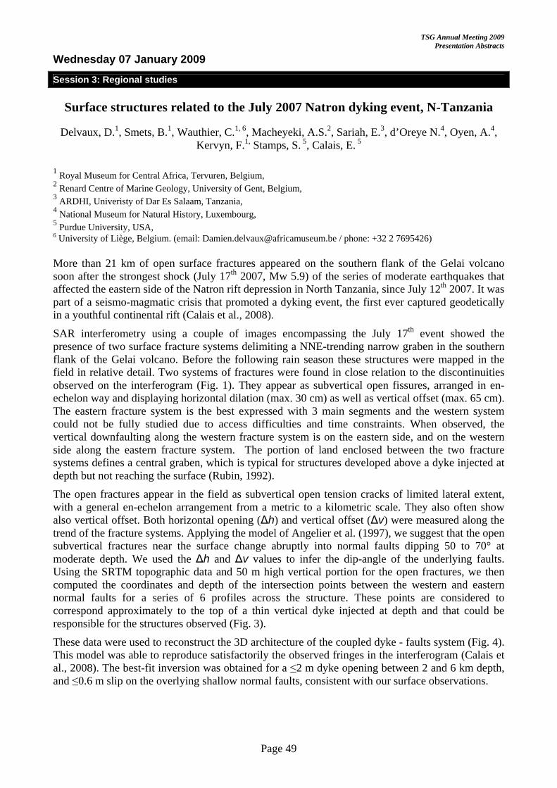
TSG Annual Meeting 2009 Presentation Abstracts
Page 49
Wednesday 07 January 2009
Session 3: Regional studies
Surface structures related to the July 2007 Natron dyking event, N-Tanzania
Delvaux, D.1, Smets, B.1, Wauthier, C.1, 6, Macheyeki, A.S.2, Sariah, E.3, d’Oreye N.4, Oyen, A.4, Kervyn, F.1, Stamps, S. 5, Calais, E. 5
1 Royal Museum for Central Africa, Tervuren, Belgium, 2 Renard Centre of Marine Geology, University of Gent, Belgium, 3 ARDHI, Univeristy of Dar Es Salaam, Tanzania, 4 National Museum for Natural History, Luxembourg, 5 Purdue University, USA, 6 University of Liège, Belgium. (email: [email protected] / phone: +32 2 7695426) More than 21 km of open surface fractures appeared on the southern flank of the Gelai volcano soon after the strongest shock (July 17th 2007, Mw 5.9) of the series of moderate earthquakes that affected the eastern side of the Natron rift depression in North Tanzania, since July 12th 2007. It was part of a seismo-magmatic crisis that promoted a dyking event, the first ever captured geodetically in a youthful continental rift (Calais et al., 2008).
SAR interferometry using a couple of images encompassing the July 17th event showed the presence of two surface fracture systems delimiting a NNE-trending narrow graben in the southern flank of the Gelai volcano. Before the following rain season these structures were mapped in the field in relative detail. Two systems of fractures were found in close relation to the discontinuities observed on the interferogram (Fig. 1). They appear as subvertical open fissures, arranged in en-echelon way and displaying horizontal dilation (max. 30 cm) as well as vertical offset (max. 65 cm). The eastern fracture system is the best expressed with 3 main segments and the western system could not be fully studied due to access difficulties and time constraints. When observed, the vertical downfaulting along the western fracture system is on the eastern side, and on the western side along the eastern fracture system. The portion of land enclosed between the two fracture systems defines a central graben, which is typical for structures developed above a dyke injected at depth but not reaching the surface (Rubin, 1992).
The open fractures appear in the field as subvertical open tension cracks of limited lateral extent, with a general en-echelon arrangement from a metric to a kilometric scale. They also often show also vertical offset. Both horizontal opening (Δh) and vertical offset (Δv) were measured along the trend of the fracture systems. Applying the model of Angelier et al. (1997), we suggest that the open subvertical fractures near the surface change abruptly into normal faults dipping 50 to 70° at moderate depth. We used the Δh and Δv values to infer the dip-angle of the underlying faults. Using the SRTM topographic data and 50 m high vertical portion for the open fractures, we then computed the coordinates and depth of the intersection points between the western and eastern normal faults for a series of 6 profiles across the structure. These points are considered to correspond approximately to the top of a thin vertical dyke injected at depth and that could be responsible for the structures observed (Fig. 3).
These data were used to reconstruct the 3D architecture of the coupled dyke - faults system (Fig. 4). This model was able to reproduce satisfactorily the observed fringes in the interferogram (Calais et al., 2008). The best-fit inversion was obtained for a ≤2 m dyke opening between 2 and 6 km depth, and ≤0.6 m slip on the overlying shallow normal faults, consistent with our surface observations.

TSG Annual Meeting 2009 Presentation Abstracts
Page 50
Fig. 1: Sar interferogram encom-passing the July 17th event in the southern flank of the Gelai volcano.
Fig. 3: Southern flank of Gelai volcano with surface intersection of fractures and inferred dyke at depth (SD view)
Fig. 2, from Angelier et al. (1997)
Fault Dip = Arctan (Δv / Δh) Net Slip = Sqrt (Δv2 + Δh2)
Fig. 4. 3D mixed boundary-element model used to reproduce the Sar interferogram.
References: Angelier, J., Bergerat, F., Dauteuil, O., Villemin, T., 1997. Effective tension-shear relationships in extensional fissure swarms, axial rift zone of northeastern Iceland , Journal of Structural Geology 19, 673-685.
Calais, E., d’Oreye, N., Albaric, J., Deschamps, A., Delvaux, D., Déverchère, J., Ebinger, C., Wambura R.F., Kervyn, F., Macheyeki, A.S., Oyen, A., Saria, E., Smets, B., Stamps D.S, Wauthier, C., 2008, Aseismic strain accommodation by dyking in a youthful continental rift, East Africa. Nature, paper 2008-02-01869B.
Rubin, A., 1992. Dike-induced faulting and graben subsidence in volcanic rift zones. Journal of Geophysical Research 92, 1839-1858.

TSG Annual Meeting 2009 Presentation Abstracts
Page 51
Wednesday 07 January 2009
Session 3: Regional studies
Exhumation of a Cretaceous rift complex within a Late Cenozoic restraining bend, southern Mongolia: Implications for the crustal evolution of the Gobi
Altai region
Dickson Cunningham1, Sarah Davies1, Duncan McLean2
1. Department of Geology, University of Leicester, ([email protected]) 2. MB Stratigraphy Ltd, Sheffield, UK The Gobi Altai region of southern Mongolia contains intramontane basins dominated by Jurassic-Cretaceous clastic and volcanic deposits. The origin of the basins is poorly documented because Late Cenozoic transpressional mountain building and associated alluvial sedimentation have overprinted and obscured the older Mesozoic history. In this study, we report the discovery of Cretaceous high-angle normal faults and a major low-angle extensional detachment fault bordering the Altan Uul range in southern Mongolia which indicates that NW-SE crustal stretching was responsible for creating the accommodation space for thick Jurassic-Cretaceous sedimentary accumulations in southern Mongolia. The detachment fault separates chlorite-grade meta-sedimentary rocks in the footwall from intensely sheared and flattened unmetamorphosed conglomerates and breccias in the hanging wall. The significant metamorphic break across the detachment fault, associated extensional structures in the hanging wall, and domal form of the footwall block indicates that NW Altan Uul has some structural and topographic characteristics typically associated with metamorphic core complexes. However, NW Altan Uul lacks ductile extensional fabrics along the detachment fault and in the adjacent footwall, and limited stretching in the upper plate suggests less total extensional slip than is reported from typical metamorphic core complexes. Unconformable relations in hanging wall strata and palynological data indicate that extensional detachment faulting at NW Altan Uul occurred in the Aptian (120-112 Ma) similar in time to metamorphic core complex development previously reported in Mongolia/China border areas and the Daqing Shan of northern China. Post-detachment fault Cretaceous sedimentation buried NW Altan Uul, which is only now exposed due to erosional denudation associated with uplift of the modern Nemegt-Altan Uul restraining bend. The discovery of significant Aptian crustal extension in the southern Gobi Altai suggests that Early Cretaceous diffuse rifting encompassed an even wider region than was previously recognised, including areas of the eastern Altai, central, southern and eastern Mongolia, and adjacent areas of northern and northeastern China and Transbaikalia – constituting one of Earth’s largest continental interior extensional provinces. Workers investigating the neotectonic development of the Gobi Altai should consider the extent to which the pre-existing rift basin architecture may have influenced the modern range development and network of seismically active faults in the region.

TSG Annual Meeting 2009 Presentation Abstracts
Page 52
Wednesday 07 January 2009
Session 3: Regional studies
Mid-lower crustal low viscosity channel beneath Tibet - the view from experimental rock mechanics
Julian Mecklenburgh and Ernest Rutter
Rock Deformation lab, School of Earth, Atmospheric and Environmental Science, University of Manchester, Manchester M13 9PL
High continental plateaux, like Tibet and the Andean Altiplano-Puna are characterized by very low surface relief, which suggests that they are underlain by anomalously weak material, that cannot support lateral variations of topographic elevation. The ice above Antarctic subglacial lakes shows the same effect, a remarkably flat topography. Geophysical evidence also points to the existence in Tibet of an extensive mid to lower crustal layer that may be partially molten, and hence may allow mechanical detachment between the upper most crust and lower crust/upper mantle. Magnetotelluric soundings (Unsworth et al. 2005) have revealed a mid-crustal high electrical conductivity layer; seismic studies demonstrate mid-crustal low velocities (Rapine et al. 2003).
In attempt to model the mechanics of Tibet, (Shen et al. 2001) inferred the existence of a weak, partially molten layer of reduced viscosity (1012 Pa s if the layer were 250 m thick, ranging to 1018 Pa s if the layer were only 15 km thick)
Linear viscosity in the channel was assumed to vary as
00 exp z zμ μ
α−⎛ ⎞= ⎜ ⎟
⎝ ⎠
where z is depth in km, 0μ is the viscosity of the upper crust in Pa s, α is the viscosity decay
coefficient in km and 0z is the depth of the top of the weak channel. This formulation was not constrained in any way by experimental studies of the rheology of crustal rocks under appropriate conditions.
We have recently carried out experiments (Mecklenburgh & Rutter 2003, Rutter et al. 2006) in the flow of partially molten granitoid, yielding a flow law as a function of stress, temperature and melt fraction, with a water content of 2.5 wt%:
These data and the resultant flow law can be compared to the geophysical constraints on mechanics of Tibet, additionally using the melting experiments of Harris et al. (2000) to constrain melt fraction versus temperature. The experimental data, extrapolated to expected stresses and temperature in nature, predict satisfactorily the inferences made by Shen et al. (2001) from modelling constrained by geophysical data. Solid state deformation controlled by quartz rheology is not sufficient to explain the geophysical observations.
In the experiments a constant grain size for the solid fraction of 50 micron was used. Although we have no data on the effects of varying grain size, we can make the assumption that increasing grain size reduces deformation rate in proportion to reciprocal grain size squared. This has the effect of stiffening the partially molten layer, but the expected behaviour still lies with the geophysical constraints.
We conclude that inferences of the existence of a partially molten detachment layer beneath Tibet are consistent with the constraints imposed by laboratory rock mechanics experiments on partially molten granitoid.

TSG Annual Meeting 2009 Presentation Abstracts
Page 53
Wednesday 07 January 2009
Session 4: Mass transport complexes and slumping
The structural geology of mass transport complexes
Rob Butler1 and Bill McCaffrey2
1University of Aberdeen ([email protected]) 2University of Leeds ([email protected]) Mass wasting is a common process on continental margins – potentially tsunamogenic and, in their ancient, subsurface deposits, create important permeability anomalies within deepwater successions. The internal structure of mass transport complexes and the processes that create them can be addressed using combinations of seismic imaging and outcrop analogues. Classical approaches stress the differences in internal architecture, especially the degree of stratal disruption, as reflecting different emplacement mechanisms (e.g. sliding or flow) and transition in process (the slump-debris flow-turbidity current spectrum) with implicit variations in emplacement rate. There are parallels with the research history into tectonic thrust belts and their internal strains where early work focussed on using strain patterns to deduce emplacement mechanics (e.g. gravity spreading vs gravity sliding). However, an important advance in thrust belts came with the recognition that strains commonly relate to kinematic evolution – especially the role of differential movement in three dimensions, rather than be diagnostic of large-scale mechanics. These issues can be conceptualized in terms of strain localization – which need have no large-scale mechanical significance. Similarly the distribution of layer-contraction and layer-extension structures can relate to local differential movement rather than have specific slope-position relevance. In analysing mass transport complexes, the key components to identify are – exotic material transported from a position significantly higher on the slope, and remobilized sediment from the local slope. Addition of material can play two competing roles: by increasing the mass of the translating material it adds to the driving force; the distribution of deformation into the surrounding material acts to dissipate energy. The degree of substrate entrainment during emplacement, reflects the efficiency of the basal slide surface and its shear strength relative to that of the surrounding sediment. The relative timing of internal deformation and slip can be charted using growth strata. All these behaviours can be examined in terms of strain partitioning, between basal slip and internal deformation. It remains unclear how different strain partitioning styles may relate to strain rate, and the rate of emplacement of submarine mass transport complexes. Examples will be presented from combinations of seismic data, and outcrops, especially from the Miocene basins of Italy.

TSG Annual Meeting 2009 Presentation Abstracts
Page 54
Wednesday 07 January 2009
Session 4: Mass transport complexes and slumping
Interpreting small complex datasets of slump features: examples from the lateral parts of a Middle Ordovician slump sheet within the Anglo-Brabant
deformation belt (Belgium)
Timothy N. Debacker, Mathijs Dumon & Anouk Matthys
Ghent University, Geology & Pedology, Krijgslaan 281, S8, 9000 Gent, Belgium Many different methods exist for determining palaeoslope orientation and slump direction and sense. All these methods are based on certain assumptions, which are not necessarily the same as those used in the other methods. Unfortunately, most studies remain rather vague on the fact how to decide between the different methods and their specific assumptions. Another unfortunate feature lies in the fact that all methods use a statistical approach and essentially rely on a large number of data. In the field, however, geologists usually do not have access to an enormous dataset. As pointed out by Woodcock (1979), and further developed by Bradley & Hanson (1998) and Strachan & Alsop (2006) a way to avoid these problems is by applying as many methods as possible on the same dataset. Still, published examples of studies using only a small number of slump folds are rare, and so are publications in which slump folds are interpreted to have formed in the lateral parts of slump sheets.
In this study we present an interpretation of a small, complex dataset of slump-related features from within the Lower Palaeozoic Anglo-Brabant Deformation Belt (Belgium). Within the Middle Ordovician of the Anglo-Brabant Deformation Belt, the only three existing studies of slump fold geometries have concluded a roughly S-dipping palaeoslope (Debacker, 2001; Beckers, 2003, 2004; Beckers & Debacker, 2006; Debacker & De Meester, in press). In all three cases, slump folds are sub-parallel to the deduced palaeoslope trend and combined, these studies suggest the presence of an S-dipping palaeoslope of regional extent. The present study focuses on Middle Ordovician slump folds and related features in the Thy area, situated in between the area studied by Beckers (2003, 2004; cf. Beckers & Debacker, 2006) to the east and the areas studied by Debacker (2001) and Debacker & De Meester (in press) to the west.
The slump origin of the folds under study is determined using several groups of criteria. Firstly, the relationship of the folds with respect to regional cleavage and quartz veins was examined, in order to distinguish pre- from syn-cleavage folds, and to distinguish folds formed prior to quartz vein development from those formed together with or after veining. Secondly, for the pre-cleavage and pre-veining folds, we took into account “classical slump fold characteristics”. Thirdly, we also took into account regional considerations. In our example, this approach allowed distinguishing slump folds from syn-cleavage “hard-rock” tectonic folds. The vast majority of the slump folds are oriented at high angles to regional strike, and in several cases contrasting asymmetries were observed for folds of roughly the same orientation.
In order to restore regional bedding and slump folds to horizontal, for each slump fold we used the local regional bedding and the local syn-cleavage fold axis. For the determination of palaeoslope orientation and slump direction and sense, only the larger and best preserved slump folds were used, without those with an ambiguous geometry or asymmetry and without the small parasitic folds within the limbs of larger slump folds.
On the small dataset of suitable slump folds we applied six methods: 1) the mean axis method, 2) the separation arc method, 3) the axial surface intersection method, 4) the fold interlimb fold azimuth method, 5) the fold interlimb axial surface strike method and 6) the axial surface dip and
TSG Annual Meeting 2009 Presentation Abstracts
Page 55
dip direction method. Methods 1 to 4 have been applied before, and method 5 is analogous to method 4 (cf. Strachan & Alsop, 2006). As a method, method 6 is new, although axial surface dip has been plotted against dip direction in fabric topology plots in Strachan & Alsop (2006). As a final step in the analysis we recommend that possible slump senses and directions suggested by each method are compared graphically. Ideally, true slump sense and direction should be situated within the zone of overlap of the results of the majority of the methods applied. In doing so, again, one should take into account the assumptions and draw-backs of each method.
For our small complex dataset, method 1 does not allow drawing conclusions. As there is full overlap between clockwise and anticlockwise fold asymmetries, also method 2 is non-conclusive. In the assumption that the intersection of the axial surfaces is parallel to the trend of the palaeoslope, method 3 gives erroneous results. Methods 4 and 5 do give a correct slump direction, but, because of the small number of data, the range is very large. In addition, slump sense is unclear. Method 6 gives quite satisfying results, both in terms of slump direction and sense. Together, these methods point to a slump direction and sense that is similar to the results of Beckers (2003, 2004; cf. Beckers & Debacker, 2006), Debacker (2001) and Debacker & De Meester (in press) and, moreover, suggest that the outcrop under study exposes the lateral parts of a slump sheet.
The results of this study are fully compatible with those from previous studies, and, moreover, have several implications for deducing slump sense from the lateral parts of slump sheets. Firstly, within the lateral parts of slump sheets, the intersection of the slump fold axial surfaces will not be sub-perpendicular to slump direction, but may, as in our case, be sub-parallel to slump direction. Secondly, within the lateral parts of slump sheets, slump fold interlimb angle will become smaller as the fold axes approach the transport direction, as previously suggested by Strachan & Alsop (2006) (see methods 4 and 5). However, contrary to the results of Strachan & Alsop (2006), this decrease in interlimb angle is not accompanied by a decrease in axial surface dip, but by an increase in axial surface dip. Possible, this latter relationship is a diagnostic feature for the lateral parts of slump sheets.
BECKERS, R., 2003. Unpublished M.Sc.-thesis, Universiteit Gent.
BECKERS, R., 2004. Geologica Belgica 7, 357-359.
BECKERS, R. & DEBACKER, T.N., 2006. Journal of the Geological Society, 163, 37-46.
BRADLEY, D. & HANSON, L., 1998. Journal of Geology, 106, 305-318.
DEBACKER, T.N., 2001. Unpublished Ph.D.-thesis, Universiteit Gent.
DEBACKER, T.N. & DE MEESTER, E. (in press). Geologica Belgica.
STRACHAN, L.J. & ALSOP, G.I., 2006. Basin Research 18, 451-470.
WOODCOCK, N.H., 1979. Sedimentology 26, 83-99.

TSG Annual Meeting 2009 Presentation Abstracts
Page 56
Wednesday 07 January 2009
Session 4: Mass transport complexes and slumping
Mass-wasting in a record of uplift and climate change: the Absheron Suite, South Caspian Basin, Azerbaijan
Steve Richardson1, Mark Allen1, Stuart Jones1, Richard Davies1, Ken McCaffrey1,2, Simon Grant2
1- Department of Earth Sciences, University, Science Labs, Durham, DH1 3LE 2- BP Exploration Operating Company Ltd, Azerbaijan Business Unit, Chertsey Road, Sunbury on Thames, Middlesex, TW16 7LN Email: [email protected]
The Absheron Suite is a Pleistocene, clastic unit deposited during the subsidence of the South Caspian Basin: successions up to 1500 m thick were rapidly deposited during incipient subduction of the rigid, oceanic, basement. Deposition was contemporaneous with fold growth in the detached sedimentary cover.
The project examines the growth strata of these folds using high quality 3D seismic data from two large anticlines offshore Azerbaijan. The stratal wedges are commonly internally deformed: many large mass transport deposits (MTDs), some over 100 km3 in volume, occur at various levels. Surface mapping, coherency and amplitude extractions have been used to visualise these features.
We present structures not normally imaged in MTDs. Detachments ramp up and down stratigraphy, sometimes even far down into the detachments of older, underlying failures. Mounded structures and sheet-like ramps are preserved on the detachment. Failures commonly emanate from faults associated with local mud volcanoes. Pockmarks are present at the surface of some slides. Transport direction indicators show most MTD’s traveling in a direction 90° from the axis, down the fold flanks along a detachment (see Figure 1). Many events however, show a transport direction parallel to the fold hinge.
A triggering mechanism for the mass wasting events is not fully constrained. Many common slide triggers (gas hydrates, sea level fluctuations, earthquakes) are potentially present in the South Caspian Basin. The slides are often spatially correlated with pre-existing faults. Diagnostic features of (overpressured) fluid escape are also present. Oblique transport directions are interpreted as being caused by the progradation of large clinoforms from the shelf edge over the structure which outpace fold uplift.
Figure 1: Four MTD transport directions observed
1) Flows down the fold flank.
2) Flows along the fold, spatially correlated with faults associated with mud volcano.
3) Flows along the fold, start of MTD not seen.
4) Flows across the fold.

Tectonics Studies Group Annual Meeting 2009
Keele University, Staffordshire5 – 8 January 2009
Poster Abstracts


TSG Annual Meeting 2009 Poster Abstracts
Page 59
Posters
Modeling Surface-Structure Development Of The Western Arm Of The Ears: Reference Area Within Longitudes 3°N And 5°S.
Aanyu, K.1,2, Koehn, D1., Passchier, C.1, Sachau T.1 .
1=Tectonophysics, Institute of Earth Sciences, Johannes Gutenberg University, Mainz - Germany. 2=Department of Geology, Makerere University, Kampala – Uganda. The northern segment of the western branch of the EARS (East African Rift System) trends NNE-SSW to N-S and consists of half-graben basins that host the lakes Albert, Edward and Kivu. The lakes Albert and Edward are separated by the Rwenzori block which is bordered by high angle normal faults to the northwest, west and southeast.
The process of fault nucleation, propagation and development in the upper crust of an evolving rift zone is here simulated by deforming a pack of fine-grained, cohesionless quartz sand in scaled extensional sandbox models. The lateral limits of basal sheets placed below the sand and attached to the extending wall present velocity discontinuity (VD) segments that mimic upward-propagating faults in the crust. Varying sizes of offset & lateral spacing between VD segments are used to study the resulting fault geometries, evolution of rifts and behavior of interacting rift segments.
Generally, axis-parallel rift-bounding faults form first and propagate before oblique faults develop. The smaller the lateral spacing between VD segments, the longer the propagation of axis-parallel rift-bounding faults. The greater the spacing, the greater the extension required before orthogonal faults form; axis-parallel faults are quickly cut off so that most of the extension is accommodated along oblique faults that connect rift segments. Different rift segments propagate past each other capturing blocks between them, which are equivalent to micro-plates in nature. Rotation is observed on some of such blocks as a result of movement accommodated within the two bounding faults. Through micro-plate capture, some segments of the rift open in directions oblique to the extension direction attesting to local alteration of the stress field.
Large offset of VD segments encourages development of more curved rift segments and offers stronger interaction between them through strike-slip movement along segments connecting oblique faults. Smaller offsets result in longer segment propagation near-parallel to the extension axis, although the widths of rifts are similar to those of large offsets.
We discuss the implications of fault geometries, age relationships and interactions at rift segments that develop in the models for structures found in the Albertine Rift System.
TSG Annual Meeting 2009 Poster Abstracts
Page 60
Posters
An onshore-offshore study of basement-influenced oblique tectonics in the South Atlantic passive margin
David Ashby1, Ken McCaffrey1, Bob Holdsworth1, Julio Almeida2, Kevin Boyd3
1Department of Earth Sciences, Durham University, Durham DH1 3LE. 2 TECTOS, Rio de Janeiro State University, Brazil 3Exploration Ltd, Chertsea Rd, Sunbury on Thames, Middlesex, TW 16 7BP
The South Atlantic passive margins vary considerably in both margin width and structural style along strike. Local variations in this style are thought to have been influenced on a margin-scale by pre-existing (‘basement’) structures during both rifting & break-up. However the mechanisms, timing and spatial patterns of reactivation and how they determine fault system location, geometry & evolution are poorly understood.
The Santos Basin in southeastern Brazil is an increasingly important region for hydrocarbon exploration. The recently announced ‘supergiant’ oil and gas discoveries of Tupi and Jupiter have highlighted the need for an understanding of the basin architecture and history.
Previous studies have interpreted the Santos Basin variously as:- 1) a basin which has been segmented along strike by transfer zones and locally reactivated during the Neogene as a result of far field stresses associated with the Andean orogeny; 2) an example of partitioned transtension formed due to oblique Neocomian to Albian rifting; and 3) a basin influenced locally by the development of a failed oceanic spreading centre during the early Cretaceous.
The aim of this project is to create an onshore tectonic elements database containing remote sensed, geophysical and published geological data to identify potential reactivated structures. Mapping of peneplain surfaces will be used to constrain the uplift history of the margin and the spatial patterns of reactivation. Many of the pre-existing basement structures and faults onshore lie significantly oblique to regional extension vectors currently proposed to explain the development of the Santos Basin. Fieldwork in the Parana to Espirito Santo regions will be carried out to constrain the reactivation history of faults and other structures, including an analysis of fault rock assemblages and overprinting relationships. Offshore, recently acquired 3D seismic data from the Santos basin will provide new insights into offshore structural geometries and the timing of rift events. These datasets will be used to 1) Create an integrated view of the influence of basement structures in the evolution of the Santos Basin, 2) reduce uncertainty in determining hydrocarbon exploration potential and risk and 3) provide new information on the role of basement inheritance during the structural evolution of continental margins.

TSG Annual Meeting 2009 Poster Abstracts
Page 61
Posters
The influence of igneous intrusions on regional post-emplacement structural and geodynamic evolution: Insights from numerical modelling of the North Pennines
Batholith, northern England.
Linda Austin1, Stuart Egan1, Stuart Clarke1 & Gary Kirby2
1Earth Sciences and Geography, School of Physical and Geographical Sciences, Keele University, Keele, Staffordshire, ST5 5BG, United Kingdom. 2British Geological Survey, Kingsley Dunham Centre, Keyworth, Nottingham, NG12 5GG, United Kingdom. The Northumberland Trough region is an area of northern England including the Northumberland Trough, its westerly continuation the Solway Basin, and the Alston Block a geomorphological high bounded to the north by the Northumberland Trough, to the west by the Vale of Eden Basin, and to the south by the Stainmore Trough. Research into the geological and geodynamic evolution of the Northumberland Trough region has provided insights into the influence of igneous intrusions on the post-emplacement structural and geodynamic development of the area. In particular, the subsidence-uplift history of the region can only be adequately explained by taking into account the emplacement of a major igneous body that has a contrasting density with the surrounding crust.
A kinematic modelling approach that includes structural, thermal and isostatic processes has been applied to the Northumberland Trough region. Initial model results generate excess subsidence of the Alston Block compared to that indicated by observed data. There is, however, little mismatch between modelled and observed subsidence within the adjacent Northumberland and Stainmore troughs. The Alston Block is underlain by the North Pennines Batholith; a non-porphyritic per-aluminous granite, intruded towards the end of the Caledonian orogeny, approximately 410Ma. It is suggested that the additional elevation of the Alston Block is due to the isostatic response of the lithosphere to the presence of this relatively buoyant granite.
The North Pennines Batholith has an average density of 2630 kg m-3; this is lower than the surrounding crustal material which has an average density of 2800 kg m-3. The North Pennines Batholith therefore acts as a negative load upon the lithosphere, which responds by isostatic uplift, resulting in differential subsidence between the Alston Block and the surrounding troughs.
Modelling of the isostatic response of the lithosphere to the North Pennines Batholith has been carried out to investigate the effects of various physical parameters, including thickness variations across the batholith, the density contrast between the crust and the batholith, and the effective elastic thickness (Te) of the lithosphere. Model results indicate that large variations in density contrast are required, in the order of 50 kg m-3, to significantly affect the amount of uplift generated by the granite. Varying Te affects the amplitude and width of the uplift generated by the granite, with increasing Te spreading the uplift over a broader area. The most important factor affecting the regional isostatic response is the thickness of the batholith, with increasing thickness initiating a greater uplift. In addition, changes in the shape of the batholith, such as varying thickness across the batholith, may act to skew the distribution of the uplift.
The shape and position of the top of the batholith are well constrained by gravity and seismic data interpretations. Also the density variation across the batholith is inferred from the density of measured samples. These data, plus hypotheses with regard to the depth of the base of the batholith, have been incorporated into the model. Model results indicate the generation of a significant amount of uplift coincident with the presence of the batholith, and show a realistic geometry and subsidence-uplift pattern across the Alston Block and adjacent basins.

TSG Annual Meeting 2009 Poster Abstracts
Page 62
Posters
Structural evolution of Triassic basins and implications on the kinematics of the Atlantic rifting; insights from the Oukaimeden and Argana Valleys, Central and
Western High Atlas of Morocco.
Catherine Baudon1*, Ivan Fabuel-Perez1, Jean Van Den Driessche2 and Jonathan Redfern1
1NARG, SEAES, The University of Manchester, Oxford Road, Williamson Building, Manchester M13 9PL 2 Géosciences Rennes, UMR-CNRS 6118, Université Rennes 1, Campus de Beaulieu 35042 Rennes cedex, France *Corresponding author. Tel.: +44 (0)1612750778; fax: +44 (0)1613069361. E-mail address: [email protected]
The structural evolution of Permo-Triassic basins in Morocco reflects the geodynamic history of North Atlantic passive margins. The Oukaimeden and Argana Valleys, located in the western and central High Atlas, provide exceptional exposures of Permo-Triassic sediments deposited in two different structural contexts although the evolution of both areas was linked to the opening of the Atlantic Ocean. More than 100 km of Paleozoic and Pre-Cambrian rocks, known as the “Massif Ancien”, separate the Oukaimeden and Argana Valleys, which were characterised by relatively similar climatic conditions at Triassic time (Fig. 1). These outcrops allow different structural styles in Triassic basins in Morocco related to the opening of the Atlantic Ocean to be investigated and offer important insights into the relative impact of tectonic and climatic controls on sedimentation.
The paucity of fine-scale dating in these Triassic sediments prevents further reliable correlation of the different units in the Argana and the Oukaimeden Valleys. However, both areas are characterised by large ENE oriented faults, associated with smaller faults mainly striking NNE. This structural orientation has been used to propose models explaining the formation and evolution

TSG Annual Meeting 2009 Poster Abstracts
Page 63
of Triassic basins in the High Atlas of Morocco. Opening of pull-apart basins along NNE-SSW striking normal-faults and bounded by large ENE trending left-lateral, strike-slip faults with a normal component has been explained at larger scale, by two main phases of extension (a first in a northern direction, followed by a second in a NW direction) (e.g. Laville and Petit, 1984; Beauchamp, 1988; Medina, 1991). Our study shows that the facies distribution of the Oukaimeden Valley is controlled by a complex interplay of tectonic and climatic controls (Baudon et al., Submitted). Geometry and sedimentary infill of the Oukaimeden Valley can be explained by a continuous extension occurred in a NW direction during the deposition of the whole Upper Triassic succession. This direction is illustrated by the near dip-slip striations on NE to NNE striking faults, associated to left-lateral movements of ENE trending structures with a strong normal component. No Permian sediments have been recorded in the Oukaimeden Valley “strictly speaking”. The first pulse of extension oriented N-S that has been suggested (Petit and Beauchamp, 1986; Medina, 1991) is represented further north in the study area where Permian sediments have been deposited and preserved. The structural evolution of the Argana Valley can not be explained in a similar manner. A first major extensional phase occurred between Upper Permian and Upper Triassic time and resulted in the development of ENE striking faults and subsequent erosion. The consistent angular inconformity between Permian and Triassic sediments supports this interpretation and also suggests that the Upper Permian sequence was tilted towards the NW prior to Upper Triassic sedimentation (Baudon et al., in prep). The deposition of the Upper Triassic sediments occurred without major structural control. Most of the sedimentation during the Upper Triassic is therefore interpreted as being deposited a sag basin controlled by subsidence or possibly a subsurface normal-fault verging towards the SE and located west of the valley. The role of the Massif Ancien appears to be of major importance regarding the structural style of these two neighboring Triassic basins during the Atlantic rifting. In addition to this, paleocurrents of the main fluvial systems are oriented towards the WSW for the Argana Valley and towards the NE for the Oukaimeden Valley. These results suggest that both sediments pathways derived from the erosion of the Massif Ancien, which played a crucial role for the provenance of Triassic continental sediments.
Baudon, C., Fabuel-Perez, I. & Redfern, J. Submitted. Structural and climatic controls on the deposition of Upper Triassic fluvial sandstones, High Atlas, Morocco. Geological Journal Special Issue 44(5).
Baudon, C., Van Den Driessche, J. & Redfern, J. in prep. Structural evolution of the Argana Valley and implications on the kinematics of the Atlantic rifting. Basin Research.
Beauchamp, J. 1988. Triassic sedimentation and rifting in the High Atlas (Morocco) In: Triassic-Jurassic Rifting. Developments in Geotectonics (edited by Manspeizer, W.) 22, 477-497.
Laville, E. & Petit, J.-P. 1984. Role of synsedimentary strike-slip faults in the formation of Moroccan Triassic basins. Geology 12, 424-427.
Medina, F. 1991. Superimposed extensional tectonics in the Argana Triassic formations (Morocco), related to the early rifting of the central Atlantic. Geological Magazine 128(5), 525-536.
Petit, J.-P. & Beauchamp, J. 1986. Synsedimentary faulting and palaeocurrent patterns in the Triassic sandstones of the High Atlas (Morocco). Sedimentology 33(6), 817-829.

TSG Annual Meeting 2009 Poster Abstracts
Page 64
Posters
Quantifying and comparing the evolution of dynamic and static elastic properties as crystalline rock approaches failure.
Oshaine Blake1, Daniel Faulkner1
1. University of Liverpool, Department of Earth and Ocean Sciences, U.K. Presenting author: [email protected] Dynamic and static elastic properties are important parameters whenever stresses and strains are considered and are needed in reservoir and engineering applications, and earthquake and fault zone studies. Dilational microcracks within rocks strongly influence these properties.
The dynamic and static elastic properties were measured for crystalline rock as it approaches failure. In this study, increasing-amplitude cyclic loading experiments were carried out to investigate and quantify the effect of microcracking on the elastic properties of Westerly Granite. The evolution of the dynamic elastic properties was recorded throughout the loading cycle whereas static measurements were limited to the region of the stress-strain curve where the gradient of the unloading cycle is ±5GPa to the subsequent loading cycle. Here, although there is hysteresis between these two curves, we assume perfect elasticity in this region. This approach allows the evolution of static elastic properties to be documented in great detail, in contrast to previous work that has generally been limited to the linear elastic region of the stress–strain curve. Increasing-amplitude stress cycling causes an increase in the density of microcracks damage which results in a decrease in P wave velocity ( 1.6%), S wave velocity ( 3.3%) and Young’s modulus ( 6% for dynamic, 10% for static), and increase in Poisson’s ratio ( 34%) at a constant stress level. Dynamic and static elastic properties also show stress-dependency during loading ( 10%, 9%, 20% and 37% increase in P and S wave velocities, and dynamic and static Young’s moduli respectively, from 18 to 97MPa). Within the first cycle (stress level up to 50% of the unconfined strength of the rock sample), the dynamic Young modulus started at a value of 62GPa and increased to a maximum of 65GPa whereas the static Young’s modulus started at 49GPa and increased to a maximum of 68GPa. As the cycle increases, both Young’s moduli reached and did not exceed the respective maximum values. There exists a general and cycle dependent linear relationship with very high correlation between the dynamic and static Young’s modulus (Es = 2.86Ed – 116GPa and Es = 3.01Ed – 126GPa for general and first cycle relationship). The gradient of the relationship seem to decrease as the cycle increases. Both the dynamic and static elastic properties results give support to the Kaiser effect, which is an effect observed in most rocks, in which acoustic emissions are not observed during the reloading of a rock until the stress exceeds its previous high value.

TSG Annual Meeting 2009 Poster Abstracts
Page 65
Posters
Influence of D1 fabric on the development of later structures within the Southern Uplands Terrane (U.K.)
Timothy N. Debacker1 & Robert E. Holdsworth2
1. Ghent University, Geology & Pedology, Krijgslaan 281, S8, 9000 Gent, Belgium 2. RRG, University of Durham, Department of Earth Sciences, Durham, DH1 3LE U.K.
The southwestern part of the Southern Uplands Terrane locally contains evidence for polyphase deformation. For example within the coastal sections of the Barlocco area, situated SW of Kirkcudbright, turbidites of the Hawick Group (Llandovery) are deformed into a sequence of NE-SW-trending, D1 fold pairs, with an associated S1-cleavage which slightly transects the D1 fold axial surfaces in a clockwise fashion (Stringer & Treagus, 1980). Within these anchizonal deposits, local, NE-SW-trending post-D1 folds occur, coaxial with the main phase structures (Cameron, 1981; Kemp et al., 1985). At present, the origin and geological significance of the local post-D1 deformation features are still a matter of debate.
During a reconnaissance field campaign in the Barlocco area, we examined the occurrence and geometry of post-D1 deformation structures. The D1 folds are upright to slightly asymmetric, with subvertical to steeply SE-dipping axial surfaces and have wavelengths ranging from decameters to several hectometers. The overall facing direction is upwards towards the NW. Post-D1 structures include (low-angle) normal faults, small kink folds, large buckle folds and a post-S1 cleavage (S2). Despite the common occurrence of post-D1 structures, sedimentological features are well preserved and allow determining the stratigraphic sense of younging throughout the section.
The most striking post-D1 features are small kink folds. These folds have wavelengths ranging from a few centimeters up to 30 centimeters. Their orientation, asymmetry and occurrence are strongly related to their position within pre-existing D1 folds. Within the upward facing, moderately to steeply SE-dipping D1 fold limbs, the kink folds have a top-to-the-SE asymmetry and gently to moderately SE-dipping axial surfaces. Less commonly, a subordinate conjugate set with a subvertical axial surface and a top-to-the-NW asymmetry occurs. By contrast, within the upward facing, steeply NW-dipping D1 fold limbs, the kink folds have a top-to-the-NW asymmetry and moderately NW-dipping axial surfaces.
In places, the kink folds are accompanied by a spaced crenulation fabric S2, oriented parallel to the axial surfaces: i.e. gently to moderately SE-dipping in the SE-dipping D1 fold limbs and moderately NW-dipping in the NW-dipping D1 fold limbs. Macroscopically, no new fabric was observed accompanying the subordinate conjugate set. The intensity of the S2 fabric varies from place to place and may appear pervasive within the pelitic units, obscuring the original S1 fabric. Within the directly adjacent, more competent, coarse-grained beds, however, macroscopically only S1 is visible and S2 does not appear to be developed. In several places, locally subhorizontal, downward facing D1 fold limbs were observed. This overturning is often due to the presence of large D2 folds. These D2 folds occur as synform-antiform fold pairs with gently dipping axial surfaces and wavelengths of several meters. The overall geometry of these folds is identical to that of the small kink folds.
The S2-fabric, small kink folds, large D2 folds and also the (low-angle) normal faults are closely related in both space and relative timing. All result from a subvertical shortening. Possibly this D2 deformation reflects a gravitational collapse of the deformation belt formed during D1. Moreover, our observations point to a close relationship between the development of small kink folds, D2 folds and S2 fabric and suggest that, depending on local conditions such as lithology, strain, strain rate, degree of metamorphism, a complete gradation may exist between local kink folds in some locations and a pervasive second cleavage fabric in others. This has important implications for the use of kink bands as palaeostress indicator.

TSG Annual Meeting 2009 Poster Abstracts
Page 66
Posters
Lithospheric-Scale Folding in Iberia from the perspective of analogue modelling
J. Fernández-Lozano1,2, D. Sokoutis1, E. Willingshofer1, G. De Vicente2, S. Cloetingh1
1 Faculty of Earth and Life Sciences. Vrije Universiteit, Amsterdam. The Netherlands. Javier.fernandez @falw.vu.nl 2 Departamento de Geodinámica. Universidad Complutense de Madrid. España. The Iberian Peninsula is characterized by the presence of regularly spaced and generally E-W to NE-SW trending mountain ranges with mainly E-W crustal thrust across the whole Peninsula. Intraplate deformation is the result of low convergence rate between the African and European plates during the Tertiary. The main topographic heights have been related to lithospheric buckling. Consequently, basement structures were reactivated as fault corridors while inversion of the Mesozoic rifts occurred. For gaining insights into the effects of different crustal and mantle rheologies, on the structural and topographic expression of lithospheric buckling, the analogue modelling approach has been employed. The experimental results demonstrate that the primary response to the velocity increase is that the strength of the ductile crust and upper ductile mantle increases, leading to an increase in lithospheric fold wavelength(s). The folding is associated with the formation of narrow mountain ranges, which are represented by upper crustal pop-ups forming the main topographic reliefs. Shortening is accommodated within the viscous crust underneath the pop-ups by homogeneous thickening leading to lateral thickness variations of the ductile crust. Experiments performed under low velocities 0.5 cm /hour (representing 7mm/year in nature) show close similarities to natural laboratory Iberia in terms of the general shape and distribution of mountain ranges and basins. According to seismic and gravity data from the Spanish Central System and Toledo Mountains it is worth noticing that the final structure of the model-sections illustrate homogeneous thickening below the pop-up structures.

TSG Annual Meeting 2009 Poster Abstracts
Page 67
Posters
High resolution monitoring of the Mam Tor landslip
Sam Green and Ernest Rutter
Rock Deformation lab, University of Manchester, Manchester M13 9PL The Mam Tor landslip (Peak district, Derbyshire, England), some 300m wide and 700 m long, is an actively creeping mass that formed initially some 3500 years ago. Constructed initially in 1815, the main highway between Sheffield and Manchester zig-zagged across it, until in 1979 it was finally closed to traffic as a result of annual damage due to slippage within the body of the landslip and at its margins.
Since 1996 the rock deformation group at Manchester have monitored the distribution of creep of the Mam Tor landslip by means of annual surveying using electronic distance measurement. In this way we have established annual creep rates of up to 50 cm per year, with some indication that creep is accentuated during years of heavy winter rainfall. This approach, however, does not allow sufficiently high resolution correlation between creep rate and groundwater level, therefore in 2005 we completed the installation of three underground, high resolution wire creep meters, an automatic rain gauge and two boreholes, instrumented with groundwater piezometers and tilt meters. Data is collected every three hours using automatic data loggers, and data can be downloaded remotely using mobile telephones.
Within the body of the landslip two 18m long wire creep meters were placed end-to-end, and the third creep wire was positioned across the southern boundary of the slip. The pattern of slip on all three creep meters is similar. In the summer period hardly any creep occurs, but during the winter months they recorded smoothly varying creep displacements of up to 15 cm. Each borehole carries two piezometers, separated by a vertical interval of about 3 m. These show a clear response to each rainfall event, rapidly increasing followed by a slow decay over several days. The time-averaged level of groundwater reflects the integrated frequency and intensity of rainfall. Rapid creep begins when average groundwater level breaches a critical threshold. This level is breached in the wintertime, but very large amounts of rainfall are required to elevate groundwater sufficiently in the summer months to instigate creep. Summer rainfall is inhibited from infiltrating the ground owing to the effects of evapotranspiration accompanying. vigorous growth of grass and ferns during the summer months. The meteorological office program MORECS was used to quantify the effects of evapotranspiration on groundwater infiltration. This study demonstrates directly this aspect of summer vegetation growth in stabilising landslippage.
Using the Coulomb friction law and measured pore water pressures, we computed an effective rheology for the disaggregated mudstone that constitutes the greater part of the volume of the landslip, relating strain rate to effective shear stress. This is very non-linear, such that a increase of shear stress by about 5% enhances shear strain rate by one-thousand-fold. This rate dependence can be expected to apply to other situations in which poorly consolidated mudrocks are sheared, such as in accretionary complexes.

TSG Annual Meeting 2009 Poster Abstracts
Page 68
Posters
Structural modelling of possible contaminant pathways below nuclear installations
Richard Haslam1, Stuart Clarke1, Peter Styles1 & Clive Auton2
1Earth Sciences and Geography, School of Physical and Geographical Sciences, Keele University, Keele, Staffordshire, ST5 5BG, United Kingdom 2British Geological Survey, Murchison House, West Mains Road, Edinburgh, EH9 3LA, United Kingdom
Dounreay Nuclear Power station is situated in northern Caithness, Scotland on complex normally faulted Devonian sedimentary rocks with a thin, intermittent cover of superficial deposits comprising predominantly glacial tills.
The principal aim of this work is to gain an understanding of processes and controls on fluid flow pathways within such complex geological terrains. The boundary between the bedrock and superficial deposits, and fracture networks within the bedrock, can have a considerable impact on the transmissivity of any possible radionuclide particles. An understanding of the bedrock-superficial boundary and the nature of how fractures and faults influence and control the transport of fluids is of key concern.
Initial work has involved the interpretation of eight reflection seismic survey lines which were collected for the United Kingdom Atomic Energy Authority (UKAEA) from within the Dounreay power station site. Each seismic survey line was imported into SMT Kingdom software and the initial stratigraphic picks for shallow bedrock strata were produced on seismic survey line UKAEA-HR-8 guided by the gamma ray log of the Nirex 1 borehole. Four main reflectors were identified and corresponding horizons were produced for each of these reflectors. A series of normal faults were identified using the seismic surveys and interpreted surface faults. Fault surfaces and polygons were produced and the data gridded to take into account the presence of these fault surfaces and produce a basic structural model.
This model with additional seismic and borehole data will form the framework for the bedrock geological model. The covering superficial deposits will be incorporated into the geological model to produce a unified model to which geological and physical properties of the subsurface may be applied.
Surface excavations at the site demonstrate that the boundary between the bedrock and superficial deposits is gradational over a zone comprising regolith at the top of the bedrock, to glacial till with considerable rock fragments at the base of the superficial deposits. Attempts will be made to model a volume to represent this gradational boundary with variable attributes in order to fully incorporate its effects on contaminant pathways.
The bedrock-superficial boundary interacts with a number of major faults (that penetrate to rockhead within the site) and a related complex fracture network. This fracture network is exceedingly well constrained in one small area of the site by a dense grid of closely spaced boreholes. It provides an opportunity to develop a well constrained discrete fracture model. This model will be used to determine relationships between fracture trends, larger scale faulting and flow pathways in order to develop and constrain stochastic techniques that can be used to incorporate the effects of fracturing on possible contaminant pathways elsewhere on the site.

TSG Annual Meeting 2009 Poster Abstracts
Page 69
Posters
Regional uplift episodes along the NE Atlantic margin constrained by stratigraphic and thermochronologic data
Simon P. Holford1, Paul F. Green2, Richard R. Hillis1, Ian R. Duddy2, Jonathan P. Turner3 & Martyn S. Stoker4
1Australian School of Petroleum, University of Adelaide, SA 5005, Australia ([email protected]) 2Geotrack International Pty Ltd, 37 Melville Road, Brunswick West, Victoria 3055, Australia 3School of Geography, Earth and Environmental Sciences, University of Birmingham, B15 2TT, United Kingdom 4British Geological Survey, Murchison House, West Mains Road, Edinburgh, EH9 3LA, United Kingdom
The magma-rich NE Atlantic passive margin provides a superb natural laboratory for studying vertical motions associated with continental rifting and the rift-drift transition. Here we present an extensive apatite fission-track analysis (AFTA) database from the British Isles which we combine with a detailed stratigraphic framework for the Cretaceous-Cenozoic sedimentary record of the NE Atlantic margin to constrain the uplift history along and inboard of this margin during the past 120 Myr. We show that the British Isles experienced a series of uplift episodes which began between 120 and 115 Ma, 65 and 55 Ma, 40 and 25 Ma and 20 and 15 Ma, respectively. Each episode is of regional extent (~100,000 sq km) and represents a major period of exhumation involving removal of up to 1 km or more of section. These uplift episodes can be correlated with a number of major tectonic unconformities recognised within the sedimentary succession of the NE Atlantic margin, suggesting that the margin was also affected by these uplift episodes. Anomalous syn- and post-rift uplift along this margin have been interpreted in terms of permanent and/or transient movements controlled by the Iceland plume, but neither the timing nor distribution of the uplift episodes supports a first-order control by plume activity on vertical motions. Each uplift episode correlates closely with key deformation events at adjacent plate boundaries, suggesting a causative link, and we examine the ways in which plate boundary forces can account for the observed uplift episodes. Similar km-scale uplift events are revealed by thermochronological studies in other magma-rich and magma-poor continental margins, e.g. SE Australia, South Africa, Brazil. The low angle unconformities which result from these regional episodes of km-scale burial and subsequent uplift are often incorrectly interpreted as representing periods of non-deposition and tectonic stability. Similar considerations have also led to an erroneous view of the post-rift stability of many continental margins. Our results indicate that km-scale regional uplift has affected many regions previously interpreted as areas of long-term stability, and that plate boundary deformation exerts the primary control on such episodes.

TSG Annual Meeting 2009 Poster Abstracts
Page 70
Posters
Faulting within Loosely Consolidated Deltaic Sediments and its Potential Impact on Fluid Migration Pathways
Loveless, Sian, Bense, Victor , Turner, Jenni
School of Environmental Sciences, University of East Anglia, Norwich, NR4 7TJ UK [email protected]
Faults influence subsurface fluid flow, acting as conduits, barriers, or demonstrating a complex combination of both types of behaviour. Most studies linking the structural architecture of faults to their hydraulic properties have been carried out in lithified sediments. However, faulting mechanisms in loosely consolidated sediments are different from those in lithified sediments. In contrast to fault zones in lithified sediment, which often experience brittle deformation with extensive damage zones, loosely consolidated sediment fault zones commonly comprise clay to gravel smearing, and minor damage zones with limited fracturing. This may result in differing fault zone hydraulic structures.
This study aims to investigate the faulting mechanisms within loosely consolidated sediments and the impact of the resultant fault-zone architecture on fluid migration.
Several outcrops south of the block-bounding Lower Loutraki fault (in the Corinth Rift Basin, Central Greece) reveal a number of minor normal faults cutting loosely consolidated deltaic sediments (coarse gravels to marls), of the hanging wall bajada. The configuration of these outcrops enables a near 3D view of the delta and faults, thus providing an opportunity to compare faulting mechanisms within heterogeneous sediment sequences.
Faults of differing magnitudes exist roughly every 2m over a 50m section. The fault which has been studied in detail has a throw of 7m and a core averaging 2m in thickness, with asymmetrical component layers. Striations indicate a degree of oblique motion, which adds complexity to the fault zone structure. Faulting mechanisms vary in their ductility; from gravel drag and clay/sand smear (with some mixing) and grain reorientation, to sand and marl lenses and wedges within double fault planes with discrete slip surfaces. Damage zones are minor, occurring only as extensional fractures within juxtaposing marls.
The limited damage zones and clay-smearing may produce compartmentalisation of aquifers in localities where frequent intra-basinal faults (throws 1 – 2 orders of magnitude less than block bounding faults) cut loosely consolidated sediments. However, the simultaneous presence of coarse sediments along the fault plane may enhance along-fault fluid flow. Thus indicating a complexity of fluid migration pathways within faulted, loosely consolidated heterogeneous sediments.
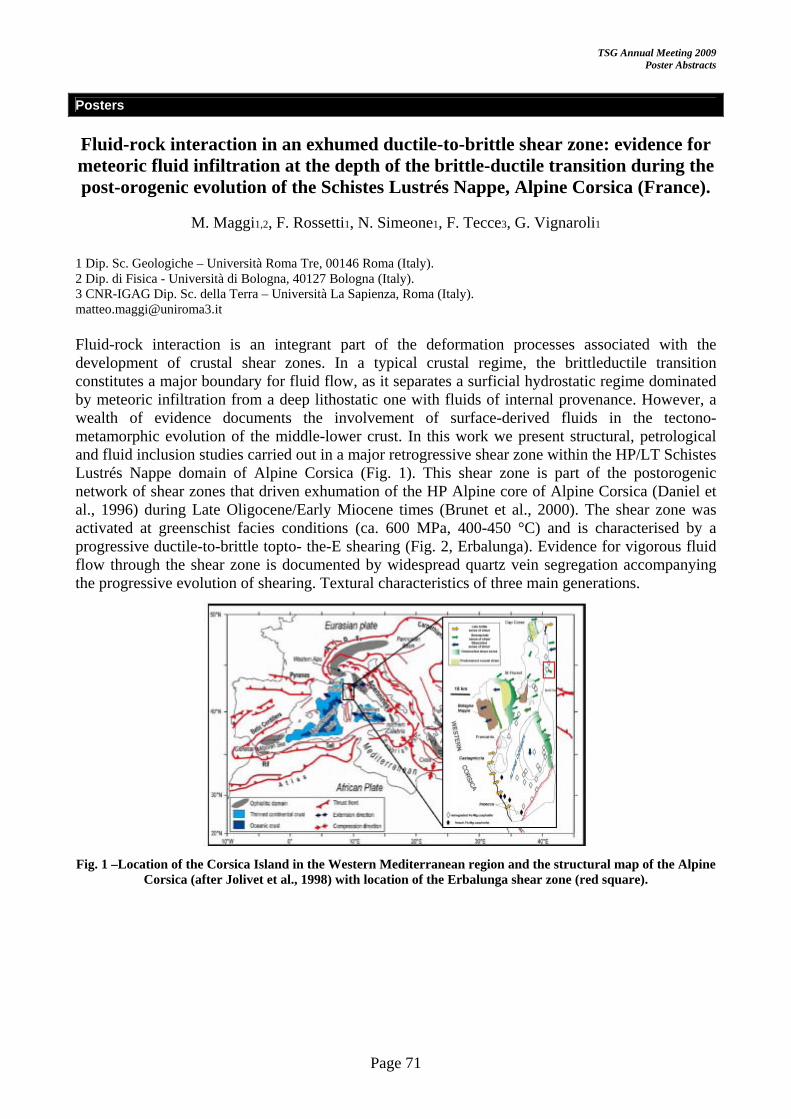
TSG Annual Meeting 2009 Poster Abstracts
Page 71
Posters
Fluid-rock interaction in an exhumed ductile-to-brittle shear zone: evidence for meteoric fluid infiltration at the depth of the brittle-ductile transition during the post-orogenic evolution of the Schistes Lustrés Nappe, Alpine Corsica (France).
M. Maggi1,2, F. Rossetti1, N. Simeone1, F. Tecce3, G. Vignaroli1
1 Dip. Sc. Geologiche – Università Roma Tre, 00146 Roma (Italy). 2 Dip. di Fisica - Università di Bologna, 40127 Bologna (Italy). 3 CNR-IGAG Dip. Sc. della Terra – Università La Sapienza, Roma (Italy). [email protected] Fluid-rock interaction is an integrant part of the deformation processes associated with the development of crustal shear zones. In a typical crustal regime, the brittleductile transition constitutes a major boundary for fluid flow, as it separates a surficial hydrostatic regime dominated by meteoric infiltration from a deep lithostatic one with fluids of internal provenance. However, a wealth of evidence documents the involvement of surface-derived fluids in the tectono-metamorphic evolution of the middle-lower crust. In this work we present structural, petrological and fluid inclusion studies carried out in a major retrogressive shear zone within the HP/LT Schistes Lustrés Nappe domain of Alpine Corsica (Fig. 1). This shear zone is part of the postorogenic network of shear zones that driven exhumation of the HP Alpine core of Alpine Corsica (Daniel et al., 1996) during Late Oligocene/Early Miocene times (Brunet et al., 2000). The shear zone was activated at greenschist facies conditions (ca. 600 MPa, 400-450 °C) and is characterised by a progressive ductile-to-brittle topto- the-E shearing (Fig. 2, Erbalunga). Evidence for vigorous fluid flow through the shear zone is documented by widespread quartz vein segregation accompanying the progressive evolution of shearing. Textural characteristics of three main generations.
Fig. 1 –Location of the Corsica Island in the Western Mediterranean region and the structural map of the Alpine
Corsica (after Jolivet et al., 1998) with location of the Erbalunga shear zone (red square).

TSG Annual Meeting 2009 Poster Abstracts
Page 72
Fig. 2 Exposure of the Erbalunga ductile-to-brittle, top-to-the-E shear zone with line drawing showing the main structures. Low-angle ductile shear bands are cut by semibrittle-to-brittle
extensional faults maintaining the same stretching direction. of quartz veins record the incremental evolution of the shear zone tracing the continuum transition from ductile- to brittle-dominated deformation environments. Regardless, of the vein generation, fluid inclusions hosted in the three different sets of quartz veins document that the circulating fluid was a low-salinity (<5% NaCl eq.) fluid. Fluid trapping occurred under pore pressure conditions fluctuating from lithostatic to hydrostatic values, as also attested by the crack-sealing textures preserved in most of the veins. The findings of this study suggest that the main source of fluid was of meteoric origin and argue for fluid percolation and infiltration at the brittle-ductile depths. This impose definition of the (i) mechanism through which superficial fluids infiltrate the mid-lower crust; and (ii) the modes (fracturing vs. ductile creep) of creation and maintenance of the structural permeability from the brittle to the ductile crust. The cyclical release of seismic energy in the brittle crust (Sibson et al., 1975) is a feasible scenario to frame the downward fluid flow in the ductile crust along pathways maintained by large scale fault zones during the postorogenic extensional collapse of the Alpine belt.
References Brunet C., Monié P., Jolivet L., Cadet J.P., 2000. Migration of compression to extension in the Tyrrhenian Sea, insight from 40Ar/39Ar ages on micas along a transect form Corsica to Tuscany. Tectonophysics 321, 127-155.
Daniel J.M., Jolivet L., Goffe B. & Poinssot C., 1996. Crustal-scale strain partitioning: footwall deformation below the Alpine Oligo-Miocene detachment of Corsica. J. Struct. Geol. 18, 41-59.
Jolivet L., Faccenna C., Goffe B., Mattei M., Rossetti F., Brunet C., Storti F., Funiciello R., Cadet J.P.,
D’Agostino N. and Parra T, 1998. Midcrustal shear zones in postorogenic extension: example from the Northern Tyrrhenian Sea. J. of Geoph. Res., 103, 12123-12160.
Sibson, R.H., Moore, J. And Rankin, A.H., 1975. Seismic pumping-hydrothermal fluid transport mechanism. J. Geol. Soc. London, 131, 653-669.

TSG Annual Meeting 2009 Poster Abstracts
Page 73
Posters
A three dimensional analysis of the geometry and kinematics of a transfer zone
D.J. Moy and J. Imber
Reactivation Research Group, Durham University, United Kingdom
Transfer zones have been widely inferred to explain segmentation of intra-continental rift systems. Defined as discrete structures of oblique and strike-slip faulting, they facilitate the transfer of strain between offset rift systems and are oriented approximately parallel to the extension direction. Previous studies of transfer zones have primarily focussed upon onshore (outcrop) examples in areas of good exposure, such as the Basin and Range Province, USA. However, the three dimensional characteristics of the transfer zone are often difficult to infer from these field studies. This study uses interpretations of commercial (offshore) 3D seismic data to assess the recognition, geometry and kinematics of transfer zones, and to compare these with previous models.
The study focuses on the Vøring Basin, offshore Norway - a Cretaceous basin on the NE Atlantic volcanic margin which formed after early Eocene continental break-up. The precursory rifts along the margin have a mainly NE-SW orientation, but regional potential field anomalies highlight a series of NW-SE trending lineaments – commonly referred to as transfer zones – along the length of the margin. An improved understanding of the nature and tectonic significance of these transfer zones is important, given their likely role in controlling the structural segmentation of basinal depocentres at a variety of scales. The principle aim of this study is to constrain the 3D architecture of a transfer zone and its kinematics during late Cretaceous-Paleocene rifting.
The NW Vøring Basin is characterised by two NE-SW trending structural highs – the Gjallar Ridge and Nyk High – that formed during Late Cretaceous-Paleocene rifting. These structural highs display a right step across the NW-SE trending “Rym Accommodation Zone”. Previous analyses of 2D seismic data suggested that the Rym Accommodation Zone accommodated sinistral strike-slip movements during Late Maastrichtian-Paleocene rifting. New interpretations of 3D seismic data from the region have not, however, found conclusive evidence for major strike-slip activity. Rather, the Rym Accommodation Zone has characteristics that are more consistent with it being a transfer zone, with oblique-slip movements along its strike controlled by the late Cretaceous rift movements within the basin. Analysis of exploration wells shows that the Rym Transfer Zone exerted a primary control upon sedimentation during rifting and also controlled the extent of lava flows and sedimentation patterns during periods of post-rift uplift in the latest Paleocene.
A further key observation is the contrast in structural styles observed across the Rym Transfer Zone. The Gjallar Ridge is characterised by half grabens formed against a series of low-angle normal faults, whilst the Nyk High comprises graben bounded by more steeply dipping, opposed-polarity normal faults. The structural model derived from the 3D seismic surveys, combined with regional structural interpretations, will be used to estimate the amount and distribution of crustal extension across the Nyk High and Gjallar Ridge, i.e. to either side of the Rym Transfer Zone. These data will be used to assess the impact of these differences in structural style upon the geometry and kinematics of the transfer zone and, in turn, to discuss their implications for the crustal structure in the NW Vøring Basin.

TSG Annual Meeting 2009 Poster Abstracts
Page 74
Posters
Mass-wasting in a record of uplift and climate change: the Absheron Suite, South Caspian Basin, Azerbaijan
Steve Richardson1, Mark Allen1, Stuart Jones1, Richard Davies1, Ken McCaffrey1,2, Simon Grant2
1- Department of Earth Sciences, University, Science Labs, Durham, DH1 3LE 2- BP Exploration Operating Company Ltd, Azerbaijan Business Unit, Chertsey Road, Sunbury on Thames, Middlesex, TW16 7LN Email: [email protected]
The Absheron Suite is a Pleistocene, clastic unit deposited during the subsidence of the South Caspian Basin: successions up to 1500 m thick were rapidly deposited, during incipient subduction of the rigid, oceanic, basement. Deposition was contemporaneous with fold growth in the detached sedimentary cover.
The project examines the growth strata of these folds using high quality 3D seismic data from two large anticlines offshore Azerbaijan. The stratal wedges are commonly internally deformed: many large mass transport deposits (MTDs), some over 100 km3 in volume, occur at various levels. Surface mapping, coherency and amplitude extractions have been used to visualise these features.
We present structures not normally imaged in MTDs. Detachments ramp up and down stratigraphy, sometimes even far down into the detachments of older, underlying failures. Mounded structures and sheet-like ramps are preserved on the detachment. Failures commonly emanate from faults associated with local mud volcanoes. Pockmarks are present at the surface of some slides. Transport direction indicators show most MTD’s traveling in a direction 90° from the axis, down the fold flanks along a detachment (see Figure 1). Many events however, show a transport direction parallel to the fold hinge.
A triggering mechanism for the mass wasting events is not fully constrained. Many common slide triggers (gas hydrates, sea level fluctuations, earthquakes) are potentially present in the South Caspian Basin. The slides are often spatially correlated with pre-existing faults. Diagnostic features of (overpressured) fluid escape are also present. Oblique transport directions are interpreted as being caused by the progradation of large clinoforms from the shelf edge over the structure which outpace fold uplift.
Figure 2: Four MTD transport directions observed
1) Flows down the fold flank.
2) Flows along the fold, spatially correlated with faults associated with mud volcano.
3) Flows along the fold, start of MTD not seen.
4) Flows across the fold.

TSG Annual Meeting 2009 Poster Abstracts
Page 75
Posters
The control of fracture patterns and connectivity on the evolution of low porosity anhydrite rocks
D. A. Sagi (1), N. De Paola (1), D. R. Faulkner (2), C. Colletini (3)
(1) RRG, Earth Sciences Department, University of Durham,UK, (2) Rock Deformation Laboratory, Department of Earth and Ocean Sciences, University of Liverpool, (3) GSG, Dipartimento di Scienze della Terra, Universita di Perugia, Italy Fluid migration in the upper crust is strongly dependent on the transport properties of rocks (i.e., permeability), which vary according to a wide range of temperature and pressure conditions and are strongly controlled by the presence of faults and fractures across a range of scales. We aim to model the critical development of permeability during progressive deformation and dilatancy of low porosity anhydrite rocks. Model parameters have been obtained from statistical microstructural analyses carried out on borehole samples from the Northern Apennines of Italy, which were deformed in a triaxial deformation and fluid-flow apparatus. Model results will be tested against porosity and permeability data obtained during the triaxial loading experiments with fluid flow performed at different effective pressures.
Previous laboratory experiments on low porosity anhydrite borehole samples from the Northern Apennines show that in the presence of deformation under non-hydrostatic stress conditions, the mode of failure, controlled by Pe, has an overwhelming effect on the evolution of permeability, compared to other factors as grain-size and fabric orientation. Dynamic permeability and porosity evolution during triaxial loading experiments is characterized by three stages: 1) an initial stage of permeability and volume reduction (compaction); 2) an intermediate stage of permeability increase (onset of intra-granular microcracking) followed by volume increase (dilation); 3) a final stage when a stable steady state permeability threshold value is attained.
Microstructural analysis on thin sections of deformed samples was carried out on microscope and SEM digital photos by digitizing grain boundaries, inter-, intra-, and transgranular fractures, fracture intersection. Statistical analysis was performed on the acquired digital dataset by the use of ImageTool to obtain mean values for grain size distribution, fracture length, fracture density, fracture apertures, grain boundary-fracture and fracture-fracture intersection point density.
The parameters obtained from the statistical analysis will be used to model the evolution of permeability during deformation in the context of different microphysical theoretical frameworks of the fracture patterns (e.g., connected porosity models vs. percolation threshold models). The comparison between the model results and the measured permeability data during laboratory experiments will aid in understanding the evolution of permeability in deforming low porosity rocks as the result of the interaction between increasing crack density, dilatancy and conducting connectivity.
The results of our study will be relevant to understand the presence of fluids and their migration in the upper crust as an important control on deformation, faulting and seismic activity. This is also of great economic significance as fluid migration in the upper crust controls the development of ore deposits, during hydrothermal fluid circulation, and oil and gas migration within hydrocarbon reservoirs and traps.

TSG Annual Meeting 2009 Poster Abstracts
Page 76
Posters
Experimental simulation of pressure solution in halite as an analogue for pressure solution in sandstones – Preliminary results
Shanvas Sathar1, Daniel Faulkner1, Richard Worden1, Craig Smalley2
1 Dept. of Earth & Ocean Sciences, University of Liverpool, Liverpool – L69 3GP, UK 2 BP Exploration, Chertsey Road, Sunbury on Thames, Middlesex – TW16 7LN, UK Presenting author: [email protected]
Pressure solution, also known as chemical compaction, is a common process occurring in sandstones and limestones. Pressure solution takes place as a result of elevated temperature and effective stress during burial and occurs by minerals preferentially dissolving into the water phase at grain contacts and diffusive transfer of the dissolved particles to zones of low effective stress such as pore spaces where they re-precipitate as mineral cements. Pressure solution is a major cause of porosity-loss and so has a big impact on reservoir quality. Understanding the effect of petroleum emplacement on pressure solution and/or mineral diagenesis is important in the economic evaluation of a petroleum basin because of its direct effect on porosity and permeability of the reservoir rocks. The effect of petroleum emplacement on pressure solution is not well known and remains controversial.
There are two contrasting hypotheses explaining the effect of oil emplacement on pressure solution. The first hypothesis supports that emplacement of oil inhibits pressure solution. This is explained by the apparent preservation of porosity in oil-bearing sandstone reservoirs widely reported in scientific literature. The second hypothesis argues that pressure solution is not at all affected by petroleum emplacement. This is supported by a) the presence of oil inclusions in quartz cements, b) the rate controlling step from kinetic calculations which is determined to be precipitation and, c) no variations in quartz cement volumes between water and oil legs.
However, mineral diagenesis is a complex process involving mineral dissolution, aqueous transport and mineral precipitation and all of these steps may have their rates influenced by petroleum emplacement. Attempted simulation of pressure solution under realistic conditions using typical reservoir minerals like quartz (sand) has been unsuccessful. Therefore experimental simulation of the effect of petroleum emplacement on pressure solution and chemical diagenesis needs to take a different approach. Rather than using largely insoluble minerals such as quartz, we are using halite (NaCl) as an analogue. These experiments were carried out to understand the suitability of halite as an analogue to sandstone in simulating pressure solution. The experiments are conducted on a customized ELE triaxial deformation apparatus. The apparatus allows experiments to be carried out under triaxial (σ1> σ2= σ3) as well as hydrostatic (σ1=σ2= σ3) pressure conditions.
Hydrostatic compaction experiments were conducted on halite in the presence of saturated halite solution as pore fluid to understand the constitutive parameters governing pressure solution. Volumetric strain of the sample was measured by the “hit point” method. The axial strain rate is observed to be directly proportional to the applied stress and shows inverse relationship to grain size. The results shows good agreement to the constitutive equation for pressure solution creep of halite aggregates reported earlier. Moreover, the overgrowths and indentations of the grains within the sintered samples under SEM suggest that pressure solution predominated over other plastic and/or brittle deformation processes. Thus, the results from the preliminary experiments suggest that halite can be used as an analogue to sandstone/s in understanding the effect of petroleum emplacement on pressure solution.
TSG Annual Meeting 2009 Poster Abstracts
Page 77
Posters
Embedding Enterprise into Geological Mapping
Spendlove, S. J., Stevenson, C. T., Turner, J. P. & Smith, M. P.
School of Geography, Earth & Environmental Sciences, Birmingham B15 2TT, UK [email protected] The principle aim of the E-cubed project is to embed enterprise into geological mapping. It has provided the opportunity to investigate the educational potential of a number of software packages. Key to this is the collaboration with Midland Valley and their field mapping initiative. This has allowed the exploration and application of industry standard, structural interpretation software (move2008), along with ArcGis and Adobe Illustrator for undergraduates.
Introduction of the software has been applied in three stages. Basic 3D block models were produced to assist in the understanding of 3D visualization for first year students, and to introduce them to move2008. Cross section restoration and validation has been examined with second year students at Crackington Haven, (see talk entitled, an extensional complex in a compressional setting, Crackington Haven, SW England. Spendlove et al.), to show what can be done with the software. The idea being that when they reach their 3rd year, they feel confident in using move2008 and other software packages, to aid in the communication and analysis of enterprise aspects, in their field mapping area. To assist them in this a number of guides have been produced, in collaboration with Midland Valley, aimed specifically at the interpretation of Field mapping data.
This work is presented here to demonstrate how we are looking to modify our field mapping course in the future, and to gain feedback and advice from other departments currently implementing similar changes.
TSG Annual Meeting 2009 Poster Abstracts
Page 78
Posters
Exploiting operating procedures in laser diffraction granulometry to investigate on the evolution of cataclastic fabrics in carbonate fault breccias
F. Storti and F. Balsamo
Dipartimento di Scienze Geologiche, Università “Roma Tre”, Largo S. L. Murialdo 1, I-00146 Roma, Italy Laser diffraction granulometry is typically and widely used for particle size distribution analyses of poorly coherent or loose rocks and, consequently for the description of many geological processes including sedimentation, rock fragmentation and soil formation. Modern laser granulometers provide the possibility of fast particle size data acquisition over a wide size range by using a variety of analytical methods, named standard operating procedures (SOP). They ensure the appropriate flexibility for analysing very different granular materials since they offer the possibility for fine tuning of several parameters controlling recirculation within sample dispersion units. Such a wide range of analytical procedures is typically used to find out the less invasive strategy for particle size determination, thus minimising instrumental bias on pristine size distributions. On the other hand, strongly invasive SOPs can significantly alter particle size distributions. We performed specific tests on poorly coherent carbonate platform fault core rocks by using a Malvern Mastersizer 2000 laser diffraction granulometer equipped with different sample dispersion and pumping systems that allowed us to use several wet and dry analytical procedures including different pump speeds, measure precision tests with and without sample ultrasonication, different dispersant liquids, and sampling precision tests. Thin sections of partially cemented cataclasites from the same fault zones were analysed to provide guidelines for the interpretation of the extreme particle size distribution variability provided by laser diffraction analyses. This allowed us to eventually exploit different SOPs as analytical tools to investigate on particle size reduction mechanisms during laser diffraction analyses. Similar behaviours are expected to occur in nature when cementation and healing are not effective, and this can significantly influence the mechanics of fault zones.

TSG Annual Meeting 2009 Poster Abstracts
Page 79
Posters
Structural Evolution of the Northern Cerberus Fossae graben system, Elysium Planitia, Mars
Joyce Vetterlein and Gerald P. Roberts
The Research School of Earth Sciences at Birkbeck and University College London, Gower Street, London, WC1E 6BT, UK To determine whether the structural evolution of the Northern Cerberus Fossae (NCF) was dominated by cryospheric melting and collapse or fault-related subsidence, we used MOC, THEMIS and HiRISE images, and MOLA data to document spatial variations in vertical offset along strike. The Fossae are a series of fractures on the martian surface that cross-cut Noachian, Hesperian and, in places, very young Late Amazonian terrain. Serial cross-sections across the fracture-related topography, from MOLA data, show that vertical offsets are not greater where fractures traverse older terrain, showing that offsets have accumulated since the formation of the Amazonian terrain. Vertical offsets are greater in the central portions of the fracture system with the profile resembling that for a single fault system. Topographic features that predate deformation are preserved on the graben floors suggesting little sediment infill, so the MOLA elevation measurements constrain total vertical offsets since the fractures formed. Deficits in vertical offset occur where fractures have not linked and remain en-echelon across relay zones, or have linked, leaving palaeo-graben-tips. This indicates that the traces of the fractures propagate along strike at the surface and intersect over time periods that are likely to be in the range of 105-106 years rather than in a single collapse event. Deficits are also in places associated with collapse pits, suggesting such collapse is the early stage of graben subsidence at propagating lateral graben tips. We use these observations to argue that the primary mechanism causing subsidence is not cryospheric melting and collapse, but faulting. This implies faulting in the last few percent of martian history.
TSG Annual Meeting 2009 Poster Abstracts
Page 80
Posters
Structural precursors to continental break-up; the Faroe Islands, NE Atlantic Margin
Richard J. Walker1, R.E. Holdsworth1, J. Imber1, D. Ellis2
1. Reactivation Research Group, Department of Earth Sciences, Durham University, Science Labs, Durham, DH1 3LE 2. Statoil (U.K.) Limited, Statoil House, 11a Regent Street, London, SW1Y 4ST During the Palaeogene, the NE Atlantic margin was subjected to extension-vector reorientation immediately prior to and during continental break-up. In the Faroes region of the margin, field observations and palaeostress analyses on structures exposed on the Faroe Islands indicate that the extension vector rotated progressively in an anticlockwise sense from NE-SW to NW-SE. Remnants of the Faroe Islands Basalt Group (FIBG) exposed on the islands were emplaced at or around sea-level and have a total stratigraphic thickness in excess of 6.6 km, requiring a comparable magnitude of subsidence. This was then followed by a period of significant uplift - perhaps in excess of a couple of kilometres – in order to bring the Faroe Islands to their current elevation. The purpose of this study is: (1) to constrain the relative timings and kinematics of structures exposed on the Faroe Islands in order to investigate the regional tectonic regime during late-continental break-up and early sea-floor spreading; and (2) to identify and describe any uplift-related structures formed subsequent to the magmatic emplacement of the FIBG.
Structures on the islands provide evidence for a 3-phase tectonic evolution: (1a) anticlockwise rotation from earlier E-W,to later NE-SW extension, accommodated by dip-slip N-S, then NW-SE trending faults. Continued NE-SW extension (1b) was accommodated by emplacement of a regionally significant NW-SE- and NNE-SSW-oriented dyke swarm. Event-1 affects the majority of the FIBG stratigraphy, resulting in thickness variations, most notably across the Judd, Brynhild and Westray fault-zones. Continued magmatism and anticlockwise rotation of the extension vector led to (2a) the emplacement of ENE-WSW and ESE-WNW conjugate dykes. Their intrusion heralds the onset of N-S crustal extension and was followed by (2b) crustal extrusion involving both E-W shortening and further N-S extension facilitated primarily by slip on ENE-WSW (dextral) and ESE-WNW (sinistral) conjugate strike-slip faults. During the final stages of this event, the regional extension vector rotates into a NW-SE orientation that was taken up predominantly on NE-SW oriented dextral-oblique-slip faults. Event-2 began towards the end of magmatism associated with the FIBG, and most likely continued through to the onset of oceanic-spreading on the Aegir ridge (ca. 54 Ma). Both events 1 and 2 display multiple generations of calcite and zeolite mineralisation as tensile and shear hydraulic veins, implying some degree of burial. Finally, (3) uplift was accommodated by reactivation of some faults, characterised by the entrainment of clastic material along fault planes, and an absence of mineralisation.
The progressive anticlockwise rotation of the extension vector identified here is consistent with the latest NE Atlantic continental break-up reconstructions, emphasising the importance of carrying out detailed field studies in addition to the more usual margin-scale modelling studies, in order to validate plate reconstructions.

TSG Annual Meeting 2009 Poster Abstracts
Page 81
Posters
Strain accumulation at the lateral tips of active normal faults: a study of extensional deformation in the Apennines, Italy
Maxwell Wilkinson1, Ken McCaffrey1, Patience Cowie2, Gerald Roberts3 & Richard Phillips2
1. Department of Earth Sciences, University of Durham, U.K. 2. Institute of Geography, School of GeoSciences, Edinburgh University, U.K. 3. The Research School of Earth Sciences, Birkbeck and University College, University of London, U.K.
The Apennines have been an area of extension since NE-ward thrusting ceased during the Pliocene. A 40 km wide array of seismically active NW-SE trending crustal-scale normal faults accommodate extension within the central Apennine Lazio-Abruzzo region. In this region the fault tips overlap and cumulative displacements and rates of displacement suggest that these faults are likely to be strongly interacting. The aim of this study is to analyse the temporal and spatial variation in throw gradients within the lateral tips of these active normal faults, with particular interest in areas where the fault tips overlap. The laser scan data will be supplemented with field observations, including kinematic measurements and structural mapping. Numerous temporal constraints on fault displacement exist for the scarps studied, including 12-18 ka periglacial surfaces constrained by dated volcanic deposits and 36Cl cosmogenic exposure dating of the scarp surfaces. These temporal constraints will allow throw rates to be calculated for individual throw profiles and hence the variation in net extensional strain rate along strike. The amalgamation of field mapping, kinematic measurements and high resolution elevation models will be used to investigate the variation in slip direction and the components of strain at sub-meter-scales within the fault tips. Subtle variation in these parameters along strike may well provide a better understanding of fault tip growth and interaction, and the dominant strain regime within which they operate. Any variation in the geometry of overlapping faults between scan sites will allow further investigation into how fault geometry controls fault tip gradient.
Laser scan (lidar) data from the Fiamignano fault scarp, in Lazio, has been processed to produce a detailed digital elevation model with 1m resolution. Cross sections have been extracted from the elevation model to provide throw profiles at metre-scale intervals along fault strike. In addition to providing information on lateral strain gradients, these sections have been used to characterize the nature of the Fiamignano fault scarp. The data have been used to quantify the amount of degradation of the footwall, the stability of the hanging wall and the volume of colluvium that has accumulated at the base of the fault plane. These data provide important constraints on the slip rate information that can be extracted from scarps that have been variably modified by Holocene surface processes.

TSG Annual Meeting 2009 Poster Abstracts
Page 82
Posters
A revised classification of fault breccias.
Nigel Woodcock and Kate Mort
Department of Earth Sciences, University of Cambridge, Downing Street, Cambridge CB2 3EQ, UK
Despite extensive research on fault rocks, and on their commercial importance, there is no non-genetic classification of fault breccias that can easily be applied in the field. The present criterion for recognising fault breccia as having no ‘primary cohesion’ is typically difficult to assess. We
propose instead that fault breccia should be defined, as with sedimentary breccia, primarily by grain size. At least 30% of its volume should comprise clasts larger than 2mm in diameter.
To subdivide fault breccias, we advocate the use of textural terms borrowed from the cave-collapse literature – crackle, mosaic and chaotic breccia – with bounds at 75% and 60% clast content. A secondary breccia discriminant, more difficult to apply in the field, is the ratio of cement to matrix between the clasts.
Revised classification of fault rocks using clast size as the primary criterion for fault breccias
Classification of fault breccia based on increasing disaggregation of the protolith
Reference Woodcock, N. H., Mort, K., 2008. Classification of fault breccias and related fault rocks. Geological Magazine 145 435-440.

Tectonics Studies Group Annual Meeting 2009
Keele University, Staffordshire5 – 8 January 2009
Fieldtrip Information


TSG Annual Meeting 2009 Fieldtrip Information
Page 85
Thursday 8th January 2009
Fieldtrip
Tectonic Studies Group 2009: Field Excursion, January 9th
The southern sector of the Dent Fault: Dentdale and Barbondale
Leader: Dr Chris Thomas, Northern England Project, British Geological Survey, Murchison House, Edinburgh. EH9 3LA
The Dent Fault in Barbondale: Lower Palaeozoic rocks to the west (left) are faulted against Carboniferous rocks to the east. The fault defines the valley floor. View to the north.
Picture: C Thomas © BGS, NERC
Aims The Dent Fault is one of the major basin-bounding structures in N England, defining the western margin of the Askrigg Block. This short field excursion will allow participants to examine various features of the Dent Fault system along parts of its southern sector on the southern side of Dentdale and in Barbondale. Key among these will be exposures that are interpreted to demonstrate the presence of a positive flower structure in the col between Barbondale and Dentdale, deformation in the Carboniferous rocks on the eastern side of the fault and landscape views combined with new mapping that confirm a major c. 500m sinistral transverse offset in the Dent Fault in southern Barbondale.
Health and Safety Weather: The field area is often subject to inclement weather, due to its elevated position. It is likely to be cold and windy. The fieldtrip may be cancelled if the weather is very poor. Participants should ensure that they have appropriate water- and windproof outer clothing and plenty of warm layers. Hats and gloves are advisable.
Footwear: The exposures are in rough field pasture and stream sections, but we will not be walking long distances up hills. Exposed rock surfaces will be slippery. Strong wellingtons with good cleated soles or walking boots are required. No trainers!
Road safety: We will be working adjacent to a very narrow hill road with limited access, verges and passing places. Stone walls adjacent to the road add to the restricted space. You will need a high visibility vest or similar.
Field equipment: No hammers please. Hard hats will be unnecessary.
Food: Ensure you bring food with you as time in the field will be short and there are no handily placed shops. A flask of tea or coffee might be a good idea!

TSG Annual Meeting 2009 Fieldtrip Information
Page 86
Thursday 8th January 2009
Fieldtrip: Safety information for participants
The fieldtrip forms part of the conference and is included in the registration fee for full-length residential and non-residential delegates. Despite this, the trip is not compulsory and delegates can opt out if they wish. Day-delegates are also welcome to joint the trip by paying a small extra cost.
The following text details important points relating to insurance and safety whist on the fieldtrip and by attending the trip you agree to all terms set out on this page completely and without prejudice.
• The trip is organized by Dr Chris Thomas of the British Geological survey and Keele University department of the Earth Sciences. It will be lead by Dr Chris Thomas. In order to ensure the safety of all participants as far as possible, the organizers reserve the right to limit or refuse attendance on the field trip.
• The attendees of the fieldtrip must take responsibility for their own and other participants’ safety. Should you be unsure either of the risks involved or your suitability for the fieldtrip, you must seek advice from the organizers.
• You must declare any disabilities or medical conditions that may affect your ability to attend the fieldtrip safely.
• You must wear appropriate clothing for the locality, time or year, and as recommended. Anticipate potential changes in weather conditions through the day that may include extreme winter conditions.
• Children and animals are not allowed on the fieldtrip.
• The organizers reserve the right not to run the trip, or to cut short the trip, if weather conditions are considered to be, or become, unsafe.
• The leader’s decision is final on any and all matters relating to the fieldtrip.
• The leader(s) is/are not expected to provide First Aid. Ensure that you have adequate supplies for your own needs.
You are not insured by BGS/NERC or by Keele University to attend this fieldtrip. You must ensure that you have insurance provided by your employer or by personal policy to adequately cover to your needs for the full extent of the trip and all that it entails.

Tectonics Studies Group Annual Meeting 2009
Keele University, Staffordshire5 – 8 January 2009
Delegate List


TSG Annual Meeting 2009 Delegate List
Page 89
Full Name Job Title Company Email Ms Kevin Aanyu student Johannes Gutenberg
Universität Mainz [email protected]
Dr Mark Allen Reader University of Durham [email protected] Mr David Ashby Postgraduate
Research Student
Department of Earth Sciences, Durham University
Miss Linda Austin Research Student Keele University [email protected] Dr Fabrizio Balsamo Dr Roma Tre University [email protected] Dr Catherine Baudon PDRA The University of
Manchester [email protected]
PhD Isaac Berwouts PhD Geodynamics & Geofluids Research Group, K.U.Leuven
Mr Oshaine Blake PhD Student University of Liverpool [email protected] Mr Herman Boro PhD student Vrije Universiteit [email protected] Prof Rob Butler [email protected] Dr Dickson Cunningham Senior Lecturer University of Leicester [email protected] Dr Timothy Debacker Postdoctoral
researcher Ghent University [email protected]
Mr Damien Delvaux Structural Geologist
Royal Museum for Central Africa
Dr Stuart Egan Senior Lecturer Keele University [email protected] Miss Magdalena Ellis Graduate Student University of Texas at
Austin, Bureau of Economic Geology
Mr Javier Fernández-Lozano
PhD student VU Universiteit [email protected]
dr. Laszlo I Fodor senior researcher Geological Institute of Hungary
Mr. Peter Hargrove [email protected] Mr Richard Haslam Research Student Keele University [email protected] Miss Alexandra Henderson
PhD Student Lancaster University [email protected]
Dr Simon Holford ARC Australian Postdoctoral Fellow
University of Adelaide [email protected]
Dr David Iacopini Post doc Research Fellow
University of Aberdeen [email protected]
Dr Jonathan Imber Lecturer Durham University [email protected] Mr John Kelly Exploration
Geoscientist Shell International Exploration and Production
Dr Maarten Krabbendam
British Geological Survey
Miss Amelie LeDuc PhD Research Student
Department of Earth Sciences
Dr Graham Leslie Geologist British Geological Survey
Prof Richard Lisle Professor Cardiff University [email protected] Mr Jonathan Long PhD Student Durham University [email protected] Miss Sian Loveless UEA [email protected]

TSG Annual Meeting 2009 Delegate List
Page 90
Mr John MacDonald [email protected] Dr Matteo Maggi [email protected] Miss Jennifer Martin Postgraduate
Student Durham University [email protected]
Ms Nicola McCabe Geoscientist Rock Deformation Research Ltd.
Dr Ken McCaffrey Lecturer Durham University [email protected] Dr Julian Mecklenburgh PDRA University of
Manchester [email protected]
Dr David Meredith Keele University [email protected] Mr David Moy PhD Student Durham University [email protected] Miss Victoria O'Connor Geologist Rock Deformation
Research [email protected]
Professor David Prior Professor University of Liverpool [email protected] Mr Steve Richardson [email protected] Dr Stephen Rippington Geologist, Arctic
& Russian Studies
CASP, University of Cambridge
Mr David Sagi PhD student University of Durham [email protected] Mr Shanvas Sathar PhD Student University of Liverpool [email protected] Miss Samantha Spendlove
Project Development Co-Ordinator
The University of Birmingham
Dr Carl Stevenson Lecturer University of Birmingham
Dr Ian Stimpson Lecturer Keele University [email protected] Prof Peter Styles [email protected] Dr Chris Thomas Principal
Geologist British Geological Survey
Dr Sue Treagus
School of Earth, Atmosphere & Environmental Sciences
Dr. Michiel van Noorden Structural Geologist
Badley Geoscience Ltd. [email protected]
PhD Koen Van Noten PhD Geodynamics and Geofluids Research Group, K.U.Leuven
Mr Richard Walker PhD research student
Durham University [email protected]
Prof. John Walsh Professor University College Dublin
Prof. John Wheeler [email protected] Mr Maxwell Wilkinson PhD research
student Univeristy of Durham [email protected]
Professor Graham Williams
Dr Paul Wilson Research Associate
University of Manchester
Dr Nigel Woodcock Reader University of Cambridge

Tectonics Studies Group Annual Meeting 2009
Keele University, Staffordshire5 – 8 January 2009
Maps & Directions


TSG Annual Meeting 2009 Map & Directions
Page 93
Holiday Inn Hotel, Keele and general area

TSG Annual Meeting 2009 Map & Directions
Page 94
Keele University