Embed Size (px)
Citation preview

Technology File and Display Resource FileUser Guide
Product Version 4.4.6April 2001
1995-2000 Cadence Design Systems, Inc. All rights reserved.Printed in the United States of America.
Cadence Design Systems, Inc., 555 River Oaks Parkway, San Jose, CA 95134, USA
Trademarks: Trademarks and service marks of Cadence Design Systems, Inc. (Cadence) contained in thisdocument are attributed to Cadence with the appropriate symbol. For queries regarding Cadence’s trademarks,contact the corporate legal department at the address shown above or call 1-800-862-4522.
All other trademarks are the property of their respective holders.
Restricted Print Permission: This publication is protected by copyright and any unauthorized use of thispublication may violate copyright, trademark, and other laws. Except as specified in this permission statement,this publication may not be copied, reproduced, modified, published, uploaded, posted, transmitted, ordistributed in any way, without prior written permission from Cadence. This statement grants you permission toprint one (1) hard copy of this publication subject to the following conditions:
1. The publication may be used solely for personal, informational, and noncommercial purposes;2. The publication may not be modified in any way;3. Any copy of the publication or portion thereof must include all original copyright, trademark, and other
proprietary notices and this permission statement; and4. Cadence reserves the right to revoke this authorization at any time, and any such use shall be
discontinued immediately upon written notice from Cadence.
Disclaimer: Information in this publication is subject to change without notice and does not represent acommitment on the part of Cadence. The information contained herein is the proprietary and confidentialinformation of Cadence or its licensors, and is supplied subject to, and may be used only by Cadence’s customerin accordance with, a written agreement between Cadence and its customer. Except as may be explicitly setforth in such agreement, Cadence does not make, and expressly disclaims, any representations or warrantiesas to the completeness, accuracy or usefulness of the information contained in this document. Cadence doesnot warrant that use of such information will not infringe any third party rights, nor does Cadence assume anyliability for damages or costs of any kind that may result from use of such information.
Restricted Rights: Use, duplication, or disclosure by the Government is subject to restrictions as set forth inFAR52.227-14 and DFAR252.227-7013 et seq. or its successor.

Technology File and Display Resource File User Guide
Contents
Preface .......................................................................................................................... 11
Related Documents . . . . . . . . . . . . . . . . . . . . . . . . . . . . . . . . . . . . . . . . . . . . . . . . . . . . . 11Typographic and Syntax Conventions . . . . . . . . . . . . . . . . . . . . . . . . . . . . . . . . . . . . . . . 12
Syntax Conventions . . . . . . . . . . . . . . . . . . . . . . . . . . . . . . . . . . . . . . . . . . . . . . . . . . 12Data Types . . . . . . . . . . . . . . . . . . . . . . . . . . . . . . . . . . . . . . . . . . . . . . . . . . . . . . . . . 13SKILL Syntax Examples . . . . . . . . . . . . . . . . . . . . . . . . . . . . . . . . . . . . . . . . . . . . . . . 15
1About the Technology File and Display Resource File . . . . . . . 16
Design Framework II Technology Data . . . . . . . . . . . . . . . . . . . . . . . . . . . . . . . . . . . . . . 17Files Containing Technology Data . . . . . . . . . . . . . . . . . . . . . . . . . . . . . . . . . . . . . . . 17How Technology Data Fits into and Is Used in the Design Flow . . . . . . . . . . . . . . . . 18
The Technology File . . . . . . . . . . . . . . . . . . . . . . . . . . . . . . . . . . . . . . . . . . . . . . . . . . . . . 18Technology File Development and Usage . . . . . . . . . . . . . . . . . . . . . . . . . . . . . . . . . 19Technology File Organization . . . . . . . . . . . . . . . . . . . . . . . . . . . . . . . . . . . . . . . . . . . 20
The Display Resource File . . . . . . . . . . . . . . . . . . . . . . . . . . . . . . . . . . . . . . . . . . . . . . . . 29Display Resource File Development and Usage . . . . . . . . . . . . . . . . . . . . . . . . . . . . 29Display Resource File Organization . . . . . . . . . . . . . . . . . . . . . . . . . . . . . . . . . . . . . . 31
How the Technology File and Display Resource File Work Together . . . . . . . . . . . . . . . . 32Command Interpreter Window Pull-Down Menu Commands . . . . . . . . . . . . . . . . . . . . . 33
Technology File CIW Pull-Down Menu Commands . . . . . . . . . . . . . . . . . . . . . . . . . . 34Display Resource File CIW Pull-Down Menu Commands . . . . . . . . . . . . . . . . . . . . . 35
April 2001 2 Product Version 4.4.6

Technology File and Display Resource File User Guide
Working in a Design Manager Environment . . . . . . . . . . . . . . . . . . . . . . . . . . . . . . . . . . 36
2Creating a Technology File: Methods and General Guidelines37
Methods of Initial ASCII File Creation . . . . . . . . . . . . . . . . . . . . . . . . . . . . . . . . . . . . . . . 38General Guidelines for Specifying Technology Data . . . . . . . . . . . . . . . . . . . . . . . . . . . . 38Technology File Statements . . . . . . . . . . . . . . . . . . . . . . . . . . . . . . . . . . . . . . . . . . . . . . . 39
The Technology File Include Statement . . . . . . . . . . . . . . . . . . . . . . . . . . . . . . . . . . . 39The Technology File Comment Statement . . . . . . . . . . . . . . . . . . . . . . . . . . . . . . . . . 40
3CreatingaTechnologyFile:Control,Layer,andDeviceDefinitions42
Controls . . . . . . . . . . . . . . . . . . . . . . . . . . . . . . . . . . . . . . . . . . . . . . . . . . . . . . . . . . . . . . 43Sample Controls Class . . . . . . . . . . . . . . . . . . . . . . . . . . . . . . . . . . . . . . . . . . . . . . . . 43Specifying Controls . . . . . . . . . . . . . . . . . . . . . . . . . . . . . . . . . . . . . . . . . . . . . . . . . . 44
Layer Definitions . . . . . . . . . . . . . . . . . . . . . . . . . . . . . . . . . . . . . . . . . . . . . . . . . . . . . . . 47Sample Layer Definitions Class . . . . . . . . . . . . . . . . . . . . . . . . . . . . . . . . . . . . . . . . . 47Specifying Layer Definitions . . . . . . . . . . . . . . . . . . . . . . . . . . . . . . . . . . . . . . . . . . . . 50
Devices . . . . . . . . . . . . . . . . . . . . . . . . . . . . . . . . . . . . . . . . . . . . . . . . . . . . . . . . . . . . . . 56Sample Devices Class . . . . . . . . . . . . . . . . . . . . . . . . . . . . . . . . . . . . . . . . . . . . . . . . 58Specifying Devices . . . . . . . . . . . . . . . . . . . . . . . . . . . . . . . . . . . . . . . . . . . . . . . . . . . 63
4Creating a Technology File: Generic Rules. . . . . . . . . . . . . . . . . . . . 78
Layer Rules . . . . . . . . . . . . . . . . . . . . . . . . . . . . . . . . . . . . . . . . . . . . . . . . . . . . . . . . . . . 78Sample Layer Rules Class . . . . . . . . . . . . . . . . . . . . . . . . . . . . . . . . . . . . . . . . . . . . . 79Specifying Layer Rules . . . . . . . . . . . . . . . . . . . . . . . . . . . . . . . . . . . . . . . . . . . . . . . . 80
Physical Rules . . . . . . . . . . . . . . . . . . . . . . . . . . . . . . . . . . . . . . . . . . . . . . . . . . . . . . . . . 83Sample Physical Rules Class . . . . . . . . . . . . . . . . . . . . . . . . . . . . . . . . . . . . . . . . . . . 86Specifying Physical Rules . . . . . . . . . . . . . . . . . . . . . . . . . . . . . . . . . . . . . . . . . . . . . 87
April 2001 3 Product Version 4.4.6

Technology File and Display Resource File User Guide
Electrical Rules . . . . . . . . . . . . . . . . . . . . . . . . . . . . . . . . . . . . . . . . . . . . . . . . . . . . . . . . 90Sample Electrical Rules Class . . . . . . . . . . . . . . . . . . . . . . . . . . . . . . . . . . . . . . . . . . 92Specifying Electrical Rules . . . . . . . . . . . . . . . . . . . . . . . . . . . . . . . . . . . . . . . . . . . . . 92
5Creating a Technology File: Application-Specific Rules . . . . . 95
Virtuoso Layout Editor Rules . . . . . . . . . . . . . . . . . . . . . . . . . . . . . . . . . . . . . . . . . . . . . . 96Sample Layout Editor Rules Class . . . . . . . . . . . . . . . . . . . . . . . . . . . . . . . . . . . . . . . 97Specifying Layout Editor Rules . . . . . . . . . . . . . . . . . . . . . . . . . . . . . . . . . . . . . . . . . . 97
Virtuoso XL Rules . . . . . . . . . . . . . . . . . . . . . . . . . . . . . . . . . . . . . . . . . . . . . . . . . . . . . . 99Sample Virtuoso XL Rules Class . . . . . . . . . . . . . . . . . . . . . . . . . . . . . . . . . . . . . . . 100Specifying Virtuoso XL Rules . . . . . . . . . . . . . . . . . . . . . . . . . . . . . . . . . . . . . . . . . . 100
Virtuoso Compactor Rules . . . . . . . . . . . . . . . . . . . . . . . . . . . . . . . . . . . . . . . . . . . . . . . 103Sample Compactor Rules Class . . . . . . . . . . . . . . . . . . . . . . . . . . . . . . . . . . . . . . . 104Specifying Compactor Rules . . . . . . . . . . . . . . . . . . . . . . . . . . . . . . . . . . . . . . . . . . 105
Virtuoso Layout Synthesizer (LAS) Rules . . . . . . . . . . . . . . . . . . . . . . . . . . . . . . . . . . . 112Sample Layout Synthesizer Rules Class . . . . . . . . . . . . . . . . . . . . . . . . . . . . . . . . . 113Specifying Layout Synthesizer Rules . . . . . . . . . . . . . . . . . . . . . . . . . . . . . . . . . . . . 114
Place and Route Rules . . . . . . . . . . . . . . . . . . . . . . . . . . . . . . . . . . . . . . . . . . . . . . . . . 120Sample Place and Route Rules Class . . . . . . . . . . . . . . . . . . . . . . . . . . . . . . . . . . . 121Specifying Place and Route Rules . . . . . . . . . . . . . . . . . . . . . . . . . . . . . . . . . . . . . . 124
6Creating a Display Resource File. . . . . . . . . . . . . . . . . . . . . . . . . . . . . . 142
Methods of Initial Display Resource File Creation . . . . . . . . . . . . . . . . . . . . . . . . . . . . . 143Display Resource File Contents . . . . . . . . . . . . . . . . . . . . . . . . . . . . . . . . . . . . . . . . . . . 143
What a Display Resource File Defines . . . . . . . . . . . . . . . . . . . . . . . . . . . . . . . . . . . 143Sample Display Resource File . . . . . . . . . . . . . . . . . . . . . . . . . . . . . . . . . . . . . . . . . 144
Specifying Display Resources . . . . . . . . . . . . . . . . . . . . . . . . . . . . . . . . . . . . . . . . . . . . 145Specifying Display Devices: drDefineDisplay() . . . . . . . . . . . . . . . . . . . . . . . . . . . . . 146Specifying Colors: drDefineColor() . . . . . . . . . . . . . . . . . . . . . . . . . . . . . . . . . . . . . . 147Specifying Stipple Patterns: drDefineStipple() . . . . . . . . . . . . . . . . . . . . . . . . . . . . . 148Specifying Line Styles: drDefineLineStyle() . . . . . . . . . . . . . . . . . . . . . . . . . . . . . . . 149Specifying Display Packets: drDefinePacket() . . . . . . . . . . . . . . . . . . . . . . . . . . . . . 150Specifying Display Packet Aliases: drDefinePacketAlias() . . . . . . . . . . . . . . . . . . . . 154
April 2001 4 Product Version 4.4.6

Technology File and Display Resource File User Guide
7Preparing Files for Use with a Design. . . . . . . . . . . . . . . . . . . . . . . . . 155
Generating a Technology Library . . . . . . . . . . . . . . . . . . . . . . . . . . . . . . . . . . . . . . . . . . 156Compiling an ASCII Technology File into a Library . . . . . . . . . . . . . . . . . . . . . . . . . 156Creating a New Technology Library from an Existing Technology Library . . . . . . . . 157
Checking a Technology File for Conformance to Application Requirements . . . . . . . . . 159Attaching a Technology Library to a Design . . . . . . . . . . . . . . . . . . . . . . . . . . . . . . . . . 161
Attaching a Technology Library to a Design Library . . . . . . . . . . . . . . . . . . . . . . . . . 162Attaching a Technology Library to a Design Cell or Cellview . . . . . . . . . . . . . . . . . . 163Device Definitions Used by the Software When You Attach One Technology File AfterAnother to a Design Library . . . . . . . . . . . . . . . . . . . . . . . . . . . . . . . . . . . . . . . . . . . 165
Detaching a Technology Library from a Cell or Cellview . . . . . . . . . . . . . . . . . . . . . . . . 166Ensuring Desired Display Resource File Usage . . . . . . . . . . . . . . . . . . . . . . . . . . . . . . 167
8Editing, Reusing, and Merging Technology File Data . . . . . . . 168
The Technology File Updating Process . . . . . . . . . . . . . . . . . . . . . . . . . . . . . . . . . . . . . 169Methods for Editing a Technology File . . . . . . . . . . . . . . . . . . . . . . . . . . . . . . . . . . . . . . 170Reusing a Technology File or Library to Build a New Library . . . . . . . . . . . . . . . . . . . . 170
Creating an ASCII File from a Binary Technology File . . . . . . . . . . . . . . . . . . . . . . . 170Copying a Technology Library to Use As a Basis for Creating a New Technology Library172
Loading Technology Data into Virtual Memory . . . . . . . . . . . . . . . . . . . . . . . . . . . . . . . 174Merging New Technology Data into an Existing Technology Library . . . . . . . . . . . . 174Replacing an Existing Technology File in a Technology Library . . . . . . . . . . . . . . . . 176
Editing Class Data through the CIW Pull-Down Menus . . . . . . . . . . . . . . . . . . . . . . . . . 178Class Data Accessible through the CIW Pull-Down Menus . . . . . . . . . . . . . . . . . . . 178The CIW Pull-Down Menus . . . . . . . . . . . . . . . . . . . . . . . . . . . . . . . . . . . . . . . . . . . 179Layer Browsers . . . . . . . . . . . . . . . . . . . . . . . . . . . . . . . . . . . . . . . . . . . . . . . . . . . . . 182
Editing Class Data with SKILL Functions . . . . . . . . . . . . . . . . . . . . . . . . . . . . . . . . . . . 189The Controls Class . . . . . . . . . . . . . . . . . . . . . . . . . . . . . . . . . . . . . . . . . . . . . . . . . . 189The Layer Definitions Class . . . . . . . . . . . . . . . . . . . . . . . . . . . . . . . . . . . . . . . . . . . 190The Layer Rules Class . . . . . . . . . . . . . . . . . . . . . . . . . . . . . . . . . . . . . . . . . . . . . . . 192The Physical Rules Class . . . . . . . . . . . . . . . . . . . . . . . . . . . . . . . . . . . . . . . . . . . . . 194The Electrical Rules Class . . . . . . . . . . . . . . . . . . . . . . . . . . . . . . . . . . . . . . . . . . . . 195
April 2001 5 Product Version 4.4.6

Technology File and Display Resource File User Guide
Checking a Technology File for Conformance to Cadence Application Requirements . 201Discarding an Edited Technology File from Virtual Memory (Reloading Data from Disk) . .201Saving a Technology File Edited in Virtual Memory to Disk . . . . . . . . . . . . . . . . . . . . . . 202About Unsaved Changes Message Boxes . . . . . . . . . . . . . . . . . . . . . . . . . . . . . . . . . . . 203
9Editing Class Data through CIW Pull-Down Menus: Controlsand Layer Definitions . . . . . . . . . . . . . . . . . . . . . . . . . . . . . . . . . . . . . . . . . . . . 206
Editing Controls Class Data . . . . . . . . . . . . . . . . . . . . . . . . . . . . . . . . . . . . . . . . . . . . . . 207Editing Layer Definitions Class Data . . . . . . . . . . . . . . . . . . . . . . . . . . . . . . . . . . . . . . . 210
Adding a Layer Definition . . . . . . . . . . . . . . . . . . . . . . . . . . . . . . . . . . . . . . . . . . . . . 210Editing Layer Display . . . . . . . . . . . . . . . . . . . . . . . . . . . . . . . . . . . . . . . . . . . . . . . . 214Editing Layer Attributes . . . . . . . . . . . . . . . . . . . . . . . . . . . . . . . . . . . . . . . . . . . . . . 216Renaming Layers or Purposes . . . . . . . . . . . . . . . . . . . . . . . . . . . . . . . . . . . . . . . . . 218Changing Layer Priorities . . . . . . . . . . . . . . . . . . . . . . . . . . . . . . . . . . . . . . . . . . . . . 220Adding or Editing Layer Properties . . . . . . . . . . . . . . . . . . . . . . . . . . . . . . . . . . . . . . 223Editing Multiple Layer-Purpose Pairs . . . . . . . . . . . . . . . . . . . . . . . . . . . . . . . . . . . . 226Deleting Layers . . . . . . . . . . . . . . . . . . . . . . . . . . . . . . . . . . . . . . . . . . . . . . . . . . . . . 227
April 2001 6 Product Version 4.4.6

Technology File and Display Resource File User Guide
10EditingClassDatathroughCIWPull-DownMenus:GenericRules229
Editing Layer Rules Class Data . . . . . . . . . . . . . . . . . . . . . . . . . . . . . . . . . . . . . . . . . . . 230Editing Physical Rules Class Data . . . . . . . . . . . . . . . . . . . . . . . . . . . . . . . . . . . . . . . . . 236Editing Electrical Rules Class Data . . . . . . . . . . . . . . . . . . . . . . . . . . . . . . . . . . . . . . . . 240
11Editing Class Data through CIW Pull-Down Menus:Application-Specific Rules . . . . . . . . . . . . . . . . . . . . . . . . . . . . . . . . . . . . . . 244
Editing Layout Editor Rules Class Data . . . . . . . . . . . . . . . . . . . . . . . . . . . . . . . . . . . . . 245Editing Virtuoso XL Rules Class Data . . . . . . . . . . . . . . . . . . . . . . . . . . . . . . . . . . . . . . 248Editing Virtuoso Compactor Rules Class Data . . . . . . . . . . . . . . . . . . . . . . . . . . . . . . . 252Editing Layout Synthesizer Rules Class Data . . . . . . . . . . . . . . . . . . . . . . . . . . . . . . . . 258
12Editing, Reusing, and Merging Display Resources. . . . . . . . . . 267
The Display Resource Updating Process . . . . . . . . . . . . . . . . . . . . . . . . . . . . . . . . . . . 268Methods for Editing Display Resources . . . . . . . . . . . . . . . . . . . . . . . . . . . . . . . . . . . . . 269Reusing a Display Resource File to Build a New Display Resource File . . . . . . . . . . . . 269Merging Display Resource Files . . . . . . . . . . . . . . . . . . . . . . . . . . . . . . . . . . . . . . . . . . 270
Merging Multiple Display Resource Files into One File . . . . . . . . . . . . . . . . . . . . . . 271Merging New Display Resource Data into the Display Resource Data in Virtual Memory272
Editing Display Resource Data through the CIW Pull-Down Menus . . . . . . . . . . . . . . . 274Display Resource Data Accessible through the CIW . . . . . . . . . . . . . . . . . . . . . . . . 275Changing a Display Packet Definition . . . . . . . . . . . . . . . . . . . . . . . . . . . . . . . . . . . . 275Changing a Layer Display . . . . . . . . . . . . . . . . . . . . . . . . . . . . . . . . . . . . . . . . . . . . . 276Adding Color . . . . . . . . . . . . . . . . . . . . . . . . . . . . . . . . . . . . . . . . . . . . . . . . . . . . . . . 277Editing Color . . . . . . . . . . . . . . . . . . . . . . . . . . . . . . . . . . . . . . . . . . . . . . . . . . . . . . . 279Adding a Stipple Pattern . . . . . . . . . . . . . . . . . . . . . . . . . . . . . . . . . . . . . . . . . . . . . . 279Editing a Stipple Pattern . . . . . . . . . . . . . . . . . . . . . . . . . . . . . . . . . . . . . . . . . . . . . . 281Adding a Line Style . . . . . . . . . . . . . . . . . . . . . . . . . . . . . . . . . . . . . . . . . . . . . . . . . 281
April 2001 7 Product Version 4.4.6

Technology File and Display Resource File User Guide
Editing a Line Style . . . . . . . . . . . . . . . . . . . . . . . . . . . . . . . . . . . . . . . . . . . . . . . . . . 282Adding a Display Device . . . . . . . . . . . . . . . . . . . . . . . . . . . . . . . . . . . . . . . . . . . . . . 283
Deleting Display Resources . . . . . . . . . . . . . . . . . . . . . . . . . . . . . . . . . . . . . . . . . . . . . . 284Deleting Colors, Stipples, and Line Styles . . . . . . . . . . . . . . . . . . . . . . . . . . . . . . . . 284Deleting a Display Packet . . . . . . . . . . . . . . . . . . . . . . . . . . . . . . . . . . . . . . . . . . . . . 289
Editing Display Resource Data with SKILL Functions . . . . . . . . . . . . . . . . . . . . . . . . . . 289Reloading Source Display Resource Files . . . . . . . . . . . . . . . . . . . . . . . . . . . . . . . . . . . 291Saving Display Resource Data to a File . . . . . . . . . . . . . . . . . . . . . . . . . . . . . . . . . . . . 292Testing a Display Resource File . . . . . . . . . . . . . . . . . . . . . . . . . . . . . . . . . . . . . . . . . . . 294Editing a Saved Display Resource File . . . . . . . . . . . . . . . . . . . . . . . . . . . . . . . . . . . . . 295About Save Changes Message Boxes . . . . . . . . . . . . . . . . . . . . . . . . . . . . . . . . . . . . . . 297
AForm Descriptions . . . . . . . . . . . . . . . . . . . . . . . . . . . . . . . . . . . . . . . . . . . . . . . 299
New Technology Library Form . . . . . . . . . . . . . . . . . . . . . . . . . . . . . . . . . . . . . . . . . . . . 300SKILL Function to Display Form . . . . . . . . . . . . . . . . . . . . . . . . . . . . . . . . . . . . . . . . 300
Check Technology File Form . . . . . . . . . . . . . . . . . . . . . . . . . . . . . . . . . . . . . . . . . . . . . 301SKILL Function to Display Form . . . . . . . . . . . . . . . . . . . . . . . . . . . . . . . . . . . . . . . . 301
Attach Technology Library to Design Library Form . . . . . . . . . . . . . . . . . . . . . . . . . . . . 302SKILL Function to Display Form . . . . . . . . . . . . . . . . . . . . . . . . . . . . . . . . . . . . . . . . 302
Dump Technology File Form . . . . . . . . . . . . . . . . . . . . . . . . . . . . . . . . . . . . . . . . . . . . . 303SKILL Function to Display Form . . . . . . . . . . . . . . . . . . . . . . . . . . . . . . . . . . . . . . . . 303
Load Technology File Form . . . . . . . . . . . . . . . . . . . . . . . . . . . . . . . . . . . . . . . . . . . . . . 304SKILL Functions to Display Form . . . . . . . . . . . . . . . . . . . . . . . . . . . . . . . . . . . . . . . 304
Layer Purpose Pair Editor Form . . . . . . . . . . . . . . . . . . . . . . . . . . . . . . . . . . . . . . . . . . 305Technology File – Technology File Set Up Form . . . . . . . . . . . . . . . . . . . . . . . . . . . . . . 307
SKILL Function to Display Form . . . . . . . . . . . . . . . . . . . . . . . . . . . . . . . . . . . . . . . . 307Technology File – Layer Browser Forms . . . . . . . . . . . . . . . . . . . . . . . . . . . . . . . . . . . . 308Discard Edits To Technology File Form . . . . . . . . . . . . . . . . . . . . . . . . . . . . . . . . . . . . . 309
SKILL Function to Display Form . . . . . . . . . . . . . . . . . . . . . . . . . . . . . . . . . . . . . . . . 309Save Technology File Form . . . . . . . . . . . . . . . . . . . . . . . . . . . . . . . . . . . . . . . . . . . . . . 310
SKILL Function to Display Form . . . . . . . . . . . . . . . . . . . . . . . . . . . . . . . . . . . . . . . . 310
April 2001 8 Product Version 4.4.6

Technology File and Display Resource File User Guide
Technology File – Control Form . . . . . . . . . . . . . . . . . . . . . . . . . . . . . . . . . . . . . . . . . . . 311Add Layer Purpose Pair Form . . . . . . . . . . . . . . . . . . . . . . . . . . . . . . . . . . . . . . . . . . . . 312Add Purpose Form . . . . . . . . . . . . . . . . . . . . . . . . . . . . . . . . . . . . . . . . . . . . . . . . . . . . . 314Edit Layer Purpose Pair Form . . . . . . . . . . . . . . . . . . . . . . . . . . . . . . . . . . . . . . . . . . . . 315Rename Layer Form and Rename Purpose Form . . . . . . . . . . . . . . . . . . . . . . . . . . . . . 316
Rename Layer Form . . . . . . . . . . . . . . . . . . . . . . . . . . . . . . . . . . . . . . . . . . . . . . . . . 316Rename Purpose Form . . . . . . . . . . . . . . . . . . . . . . . . . . . . . . . . . . . . . . . . . . . . . . 316
Layer Property Editor Form . . . . . . . . . . . . . . . . . . . . . . . . . . . . . . . . . . . . . . . . . . . . . . 317Add Property and Modify <property_name > Forms . . . . . . . . . . . . . . . . . . . . . . . . 318Technology File – Layer Rules Form . . . . . . . . . . . . . . . . . . . . . . . . . . . . . . . . . . . . . . . 319Technology File – Physical Rules Form . . . . . . . . . . . . . . . . . . . . . . . . . . . . . . . . . . . . . 320Technology File – Electrical Rules Form . . . . . . . . . . . . . . . . . . . . . . . . . . . . . . . . . . . . 321Technology File – LE Rules (Lsw Layers) Form . . . . . . . . . . . . . . . . . . . . . . . . . . . . . . . 322Technology File – LX Rules Form . . . . . . . . . . . . . . . . . . . . . . . . . . . . . . . . . . . . . . . . . 323Technology File – Compactor Rules Form . . . . . . . . . . . . . . . . . . . . . . . . . . . . . . . . . . . 324Technology File – LAS Rules Form . . . . . . . . . . . . . . . . . . . . . . . . . . . . . . . . . . . . . . . . 327Merge Display Resource Files (DRF) Form . . . . . . . . . . . . . . . . . . . . . . . . . . . . . . . . . . 329Display Resource Editor (DRE) Form . . . . . . . . . . . . . . . . . . . . . . . . . . . . . . . . . . . . . . 330Fill Color Editor, Outline Editor, and Color Editor Forms . . . . . . . . . . . . . . . . . . . . . . . . 332Stipple Editor Form . . . . . . . . . . . . . . . . . . . . . . . . . . . . . . . . . . . . . . . . . . . . . . . . . . . . 333Line Style Editor Form . . . . . . . . . . . . . . . . . . . . . . . . . . . . . . . . . . . . . . . . . . . . . . . . . . 334New Device Form . . . . . . . . . . . . . . . . . . . . . . . . . . . . . . . . . . . . . . . . . . . . . . . . . . . . . 335Load Form or Save Form . . . . . . . . . . . . . . . . . . . . . . . . . . . . . . . . . . . . . . . . . . . . . . . . 336
BSystem-Reserved Layers and Purposes . . . . . . . . . . . . . . . . . . . . . 337
Layers . . . . . . . . . . . . . . . . . . . . . . . . . . . . . . . . . . . . . . . . . . . . . . . . . . . . . . . . . . . . . . 338Purposes . . . . . . . . . . . . . . . . . . . . . . . . . . . . . . . . . . . . . . . . . . . . . . . . . . . . . . . . . . . . 341
CResolving Layer Errors . . . . . . . . . . . . . . . . . . . . . . . . . . . . . . . . . . . . . . . . . . 343
Adding a Layer to a Technology File . . . . . . . . . . . . . . . . . . . . . . . . . . . . . . . . . . . . . . . 344Adding a Layer by Manually Editing the Technology File . . . . . . . . . . . . . . . . . . . . . 344Adding a Layer Using Forms . . . . . . . . . . . . . . . . . . . . . . . . . . . . . . . . . . . . . . . . . . 347
April 2001 9 Product Version 4.4.6

Technology File and Display Resource File User Guide
Resolving Inconsistent Layer Names . . . . . . . . . . . . . . . . . . . . . . . . . . . . . . . . . . . . . . . 349Fixing Layers That Do Not Appear Correctly . . . . . . . . . . . . . . . . . . . . . . . . . . . . . . . . . 351
Editing a Display Packet . . . . . . . . . . . . . . . . . . . . . . . . . . . . . . . . . . . . . . . . . . . . . . 351Selecting a Different Display Packet . . . . . . . . . . . . . . . . . . . . . . . . . . . . . . . . . . . . . 351Creating a New Display Packet . . . . . . . . . . . . . . . . . . . . . . . . . . . . . . . . . . . . . . . . 351
DTechnology File and Display Resource File Examples. . . . . . 354
Technology File Example . . . . . . . . . . . . . . . . . . . . . . . . . . . . . . . . . . . . . . . . . . . . . . . . 355Display Resource File Example . . . . . . . . . . . . . . . . . . . . . . . . . . . . . . . . . . . . . . . . . . . 361
April 2001 10 Product Version 4.4.6

Technology File and Display Resource File User Guide
Preface
In this manual, you’ll learn how to create and maintain a technology file and display resourcefile, both of which define the technology information you need to create and view yourdesigns. This manual assumes you are familiar with the development and design ofintegrated circuits.
The preface discusses the following:
■ Related Documents on page 11
■ Typographic and Syntax Conventions on page 12
Related Documents
This manual includes some information about the applications that use the technology anddisplay resource files, but you should check any specific details with the documentation forthe applications you use.
The following documents give you more information about technology data, functions, andcommands, and the applications that use them:
■ For information about installing the product, see the Cadence® Installation Guide.
■ For reference information about the SKILL API for the technology file, refer to theTechnology File and Display Resource File SKILL Reference Manual.
■ For known problems and solutions for the technology file, see Technology File KnownProblems and Solutions.
■ For known problems and solutions for the display resource file, see Display ResourceEditor Known Problems and Solutions.
■ For information about new features, enhancements, and PCRs fixed in this release forthe technology file, see the Technology File Product Notes.
■ For information about new features, enhancements, and PCRs fixed in this release forthe display resource file, see the Display Resource Editor Product Notes.
■ For information about using Assura™ Diva® rules files, see the Assura DivaVerification Reference.
April 2001 11 Product Version 4.4.6

Technology File and Display Resource File User GuidePreface
■ For additional information about the technology data used with the Virtuoso® layouteditor, see “Using theTechnology File” in the Virtuoso Layout Editor User Guide.
■ For additional information about the technology data used with Virtuoso XL, see “EditingYour Technology File for Virtuoso Layout Accelerator” in the Virtuoso LayoutAccelerator User Guide.
■ For information about how the Virtuoso compactor uses symbolic data and DRC rules,see the Virtuoso Compactor Reference Manual, Chapter 1 and Appendix B.
■ For additional information about the technology data used with the Virtuoso layoutsynthesizer, see “Setting up the Technology File for LAS” in the Virtuoso LayoutSynthesizer User Guide.
■ For information about the differences between LEF technology data and the technologyfile for the Preview Silicon Ensemble™ place-and-route software, see the Preview GateEnsemble Reference, the LEF Data Map section of Chapter 4.
Typographic and Syntax Conventions
The following sections explain the syntax conventions used in this document, includingtechnology file syntax and Cadence® SKILL language syntax.
Syntax Conventions
This list describes the syntax conventions used in this document.
literal (LITERAL)Nonitalic (UPPERCASE) words indicate keywords that you mustenter literally. These keywords represent command (function,routine) or option names.
argument (z_argument)Words in italics indicate user-defined arguments for which youmust substitute a name or a value. (The characters before theunderscore (_) in the word indicate the datatypes that thisargument can take. Names are case sensitive. Do not type thedatatype and underscore (z_ ) before your arguments.)
| Vertical bars (OR-bars) separate possible choices for a singleargument. They take precedence over any other character.
April 2001 12 Product Version 4.4.6

Technology File and Display Resource File User GuidePreface
[ ] Brackets denote optional arguments. When used with OR-bars,they enclose a list of choices. You can choose one argumentfrom the list.
{ } Braces are used with OR-bars and enclose a list of choices. Youmust choose one argument from the list.
... Three dots (... ) indicate that you can repeat the previousargument. If you use them with brackets, you can specify zero ormore arguments. If they are used without brackets, you mustspecify at least one argument, but you can specify more.
argument... ;specify at least one,;but more are possible
[argument]... ;you can specify zero or more
,... A comma and three dots together indicate that if you specifymore than one argument, you must separate those arguments bycommas.
=> A right arrow points to the return values of the function. Variablevalues returned by the software are shown in italics. Returnedliterals, such as t and nil , are in plain text. The right arrow isalso used in code examples in SKILL manuals.
/ A slash separates the possible values that can be returned by aSKILL function.
Note: The language requires any characters not included in the list above. You must enterrequired characters literally.
Data Types
The following table summarizes the data type prefixes and data types used in Cadence SKILLfunctions:
Prefix Internal Name Data Type
a array array
b ddUserType Boolean
C opfcontext OPF context
April 2001 13 Product Version 4.4.6

Technology File and Display Resource File User GuidePreface
d dbobject Cadence database object (CDBA)
e envobj environment
f flonum floating-point number
F opffile OPF file ID
g general any data type
G gdmSpecIlUserType gdm spec
h hdbobject hierarchical database configuration object
l list linked list
m nmpIlUserType nmpIl user type
M cdsEvalObject —
n number integer or floating-point number
o userType user-defined type (other)
p port I/O port
q gdmspecListIlUserType gdm spec list
r defstruct defstruct
R rodObj ROD object
s symbol symbol
S stringSymbol symbol or character string
t string character string (text)
u function function object, either the name of a function (symbol) ora lambda function body (list)
U funobj function object
v hdbpath —
w wtype window type
x integer integer number
y binary binary function
& pointer pointer type
Prefix Internal Name Data Type
April 2001 14 Product Version 4.4.6

Technology File and Display Resource File User GuidePreface
SKILL Syntax Examples
The following examples show typical syntax characters used in the technology file ASCIIsyntax and SKILL.
Example 1list( g_arg1 [ g_arg2 ] ...) => l_result
This example illustrates the following syntax characters.
list Plain type indicates words that you must enter literally.
g_arg1 Words in italics indicate arguments for which you must substitutea name or a value.
( ) Parentheses separate names of functions from their arguments.
_ An underscore separates an argument type (left) from anargument name (right).
[ ] Brackets indicate that the enclosed argument is optional.
... Three dots indicate that the preceding item can appear anynumber of times.
=> A right arrow points to the description of the return value of thefunction. Also used in code examples in SKILL manuals.
l_result All SKILL functions compute a data value known as the returnvalue of the function.
Example 2needNCells( s_cellType | st_userType x_cellCount ) => t/nil
This example illustrates two additional syntax characters.
| Vertical bars separate a choice of required options.
/ Slashes separate possible return values.
April 2001 15 Product Version 4.4.6

Technology File and Display Resource File User Guide
1About the Technology File and DisplayResource File
The chapter discusses the following:
■ “Design Framework II Technology Data” on page 17
■ “The Technology File” on page 18
■ “The Display Resource File” on page 29
■ “How the Technology File and Display Resource File Work Together” on page 32
■ “Command Interpreter Window Pull-Down Menu Commands” on page 33
■ “Working in a Design Manager Environment” on page 36
April 2001 16 Product Version 4.4.6

Technology File and Display Resource File User GuideAbout the Technology File and Display Resource File
Design Framework II Technology Data
The Cadence® design framework II (DFII) technology data defines the parameters used indesign sessions. The DFII tools use the technology data as you create your designs. Thetechnology data includes layer definitions, device definitions, design rules, design applicationrules, display parameters, and plotter parameters—all of the information that defines theframework for creating designs.
Files Containing Technology Data
Most of the DFII technology data is distributed in two types of files, the technology file and thedisplay resource file, as described in this User Guide. The Abstract Editor and Diva® productsrequire their application-specific rules in separate files.
The technology file defines the materials and rules you use in your IC fabrication process.The technology file contains
■ Layer definitions
■ Device definitions
■ Layer, physical, and electrical rules
■ Rules specific to individual Cadence applications
The display resource file specifies how your layers appear on display devices. The displayresource file contains
■ Display device definitions
■ Definitions of colors, stipple patterns, line styles, and fill styles
■ Definitions of display packets, which are collections of colors, stipples, and line stylesassociated with particular display devices. A display packet specifies how you want alayer to be represented on the monitor or by a plotter. The technology file assigns adisplay packet to each layer it defines. In other words, a display resource file assigns adisplay packet to a display device or plotter, and the technology file assigns a displaypacket to each layer it defines.
The Diva rules files specify rules for Diva verification tools. For more information, refer tothe Assura Diva Verification Reference.
April 2001 17 Product Version 4.4.6

Technology File and Display Resource File User GuideAbout the Technology File and Display Resource File
How Technology Data Fits into and Is Used in the Design Flow
To run a DFII design session, you must define technology data in one or more technology filesand display resource data in one or more display resource files. You then compile thetechnology file or files to create a technology library, which contains a binary technology fileand device cellviews defined in the technology file or files. You must attach a technologylibrary to your design library to apply the appropriate parameters and rules to your design;you can also attach technology libraries to specific cells or cellviews individually. When yourun the design software, it uses the definitions in the attached technology library and displayresource files to define your design.
The Technology File
This section introduces and presents an overview of technology file development and usage.It also summarizes technology file organization, presents definitions of the various kinds ofdata defined in a technology file, and summarizes which design software applications usewhich technology file data.
April 2001 18 Product Version 4.4.6

Technology File and Display Resource File User GuideAbout the Technology File and Display Resource File
Technology File Development and Usage
The following illustrates the major steps for technology file development and usage:
Every DFII design uses a technology library. Usually, all of the designs in a design library usethe same technology library, but DFII does not require that you follow this model. You can useany number of technology libraries in your design hierarchy; their number and contentsdepend upon your design requirements. Several design libraries can share the sametechnology library, or you can attach a different technology library to one or more of thedesigns in a library.
Create ASCIItechnology file
Compile ASCIItechnology file
Attach technology libraryto design library, cell, orcellview
Compiling creates a binary technology file and generates thetechnology library defined by the technology file you compile (ormultiple files you compile together). The technology library consists ofthe binary technology file (named techfile.cds ) and the devicecellviews defined in the ASCII technology file. Note: Do not rename thebinary technology file or rearrange the file structure. Also, if you haverules files separate from the technology file, you must also file those inthe technology library subdirectory.
Attaching causes the design software to apply the technology librarydefinitions and rules to the attached design library, cell, or cellviewduring a design session.
When you open a design library, the DFII software automatically loadsthe attached technology library or libraries into virtual memory. Duringa design session, you can manipulate and edit the technology library invirtual memory; you can use the Command Interpreter Window (CIW)pull-down menus and SKILL functions to set and retrieve technologydata.
Check technology file forconformance to applicationrequirements
Checking ensures that the technology file data conforms to therequirements of the design applications with which it is to be used.
Creating an ASCII technology file with a text editor, you define thetechnology data you want to use with a particular design. The ASCIItechnology file is a readable file that can contain comments andCadence SKILL language routines in addition to the DFII technologydata. You can include all of your technology data in one ASCII file or inseveral ASCII files that you compile into a single binary file.
Run a DFII designsession
April 2001 19 Product Version 4.4.6

Technology File and Display Resource File User GuideAbout the Technology File and Display Resource File
The following example shows a design library that is “attached to,” or uses, the technology fileand the other technology data in a technology library. In this type of environment, you canshare the same technology information among several design libraries.
Technology File Organization
The technology file is organized into classes and subclasses, also referred to as sections. Aclass is a category in which data with related functions is grouped. Each class begins with theclass specifier (for example, physicalRules ), followed by a parenthetical enclosurecontaining subclass specifications (for example, orderedSpacingRules andspacingRules ), which define class data and rules.
The following section gives a brief description of the technology file classes and subclasses,plus a reference to detailed information on each. To see an example of an ASCII technologyfile, refer to Appendix D, “Technology File and Display Resource File Examples.”
Design Library Technology Library
ASCII tech filecellA cellB
view1 view2binary tech file
Diva rules file
attached to
device1
device2
Orderedspacing rulessubclassenclosure
physicalRules(
orderedSpacingRules(;( rule layer1 layer2 value );( ---- ------ ------ ----- )
( minEnclosure "cellBoundary" nwell" 0.1 )( minEnclosure "ndiff" "cont" 0.5 )
) ;end of Ordered Spacing Rules
spacingRules(;( rule layer1 layer2 value );( ---- ------ ------ ----- )
( minSpacing "ndiff" 1.0 )) ;end of Spacing Rules) ;end of Physical Rules Class
Physical rulesclassenclosure
Ending comments like these are usefulwhen searching a long file.
Spacing rulessubclassenclosure
April 2001 20 Product Version 4.4.6

Technology File and Display Resource File User GuideAbout the Technology File and Display Resource File
Technology File Classes
The technology file contains the classes of information defined in this section.
The Controls class, Layer Definitions class, and Devices class are classes that providedefinitions for design sessions.
The Controls class (controls ) assigns values to parameters you can refer to in the rulesyou define and sets user read/write permissions on individual technology file classes. You canshare parameters across rules classes. The individual subclasses
■ Define parameters for use throughout the technology file(techParams )
■ Define read/write permissions for technology file classes(techPermissions )
For more information about creating shared parameters, refer to “Controls” on page 43 .
The Layer Definitions class (layerDefinitions ) describes the layers you use in yourdesigns. These subclasses
■ Define the layers that can be used to define a layer-purpose pair(techLayers )
■ Define the purposes that can be assigned to layer-purpose pairs(techPurposes )
■ List layer-purpose pairs in priority order(techLayerPurposePriorities )
■ Define the display attributes of a layer(techDisplays )
■ Specify user-defined properties for specific layer-purpose pairs(techLayerProperties )
For more information about defining layers, refer to “Layer Definitions” on page 47 .
The Devices class (devices ) defines the devices you use with the Virtuoso® compactorand Virtuoso layout synthesizer software and the rule contact devices you use with PreviewGate Ensemble® and Preview Silicon Ensemble™ place-and-route software. You can alsocreate user-defined devices in the Devices class. The individual subclasses
■ Activate all Cadence-predefined device types(tcCreateCDSDeviceClass ) and declare Cadence-predefined
April 2001 21 Product Version 4.4.6

Technology File and Display Resource File User GuideAbout the Technology File and Display Resource File
❑ Contact devices(symContactDevice and ruleContactDevice )
❑ Enhancement devices(symEnhancementDevice )
❑ Depletion devices(symDepletionDevice )
❑ Pin devices(symPinDevice )
❑ Rectangular pin devices(symRectPinDevice )
■ Define customer, or user-defined, device types(tcCreateDeviceClass )
■ Declare devices of any type(tcDeclareDevice )
For more information about creating devices in the technology file, refer to “Devices” onpage 56 .
Generic rules classes apply across design applications and define design rules andconstraints. The Layer Rules, Physical Rules, and Electrical Rules classes are generic rulesclasses.
The Layer Rules class (layerRules ) identifies layers that can be used as vias to conductbetween routing layers and layers that are equivalent to each other. It also defines the Streamtranslation data required for translating designs from Stream format. The individualsubclasses
■ Define layers that conduct between two other layers(viaLayers )
■ List layer-purpose pairs that represent the same type of material(equivalentLayers )
■ List Stream translation data for layer-purpose pairs(streamLayers )
For more information about layer rules, refer to “Layer Rules” on page 78 .
The Physical Rules class (physicalRules ) defines the physical parameters of layers inyour layout design. Physical rules include layer spacing, overlap, and equivalence rules. Theindividual subclasses
April 2001 22 Product Version 4.4.6

Technology File and Display Resource File User GuideAbout the Technology File and Display Resource File
■ List spacing rules in which the order of layers is not important (spacingRules )
■ List spacing rules in which the order of layers is important (orderedSpacingRules )
■ Specify a multiple for grid snapping(mfgGridResolution )
For more information about creating physical rules, refer to “Physical Rules” on page 83 .
The Electrical Rules class (electricalRules ) defines the electrical characteristics ofthe layers in your design. Electrical characterization rules define resistance, capacitance, andcurrent density. The individual subclasses
■ List characterization rules in which the order of layers is not important(characterizationRules )
■ List characterization rules in which the order of layers is important(orderedCharacterizationRules )
For more information about creating electrical rules, refer to “Electrical Rules” on page 90 .
Application-specific rules classes apply only to specific design applications. They definerules that apply to specific DFII physical design applications (Virtuoso layout editor, layoutaccelerator, layout synthesizer, and compactor) and place-and-route applications (such asPreview Gate Ensemble and Preview Silicon Ensemble).
The Layout Editor Rules class (leRules ) specifies rules for the Virtuoso layout editorphysical design application. Its subclass
■ Specifies the order in which layers are displayed in the Layer Selection Window (LSW)(leLswLayers )
For more information about specifying layout editor rules, refer to “Virtuoso Layout EditorRules” on page 96 .
The Virtuoso XL Rules class (lxRules ) specifies rules for the Virtuoso layout accelerator(Virtuoso XL) physical design application. The individual subclasses
■ List the layers to be monitored by the online extractor(lxExtractLayers )
■ List the layers that cannot overlap in a Virtuoso XL design (lxNoOverlapLayers )
■ Define templates for relative object design (ROD) multipart paths (MPPs)(lxMPPTemplates )
For more information about specifying Virtuoso XL rules, refer to “Virtuoso XL Rules” onpage 99 .
April 2001 23 Product Version 4.4.6

Technology File and Display Resource File User GuideAbout the Technology File and Display Resource File
The Virtuoso Compactor Rules class (compactorRules ) specifies rules for theVirtuoso compactor design application. The individual subclasses
■ Specify how the compactor is to use specified layers(compactorLayers )
■ Define the wires used in a design(symWires )
■ Define design rules followed by the compactor(symRules )
For more information about specifying Virtuoso compactor rules, refer to “VirtuosoCompactor Rules” on page 103 .
The Layout Synthesizer Rules class (lasRules ) specifies rules for the Virtuoso layoutsynthesizer (LAS) design application. The individual subclasses
■ Specify how LAS uses layers when it automatically synthesizes a design (lasLayers )
■ Specify cells used as devices during design synthesis(lasDevices )
■ Specify wires and how they are used during design synthesis(lasWires )
■ Specify properties that control how LAS synthesizes a design (lasProperties )
For more information about specifying layout synthesizer rules, refer to “Virtuoso LayoutSynthesizer (LAS) Rules” on page 112 .
The Place and Route Rules class (prRules ) specifies rules for the place- and-routeapplications (such as Preview Gate Ensemble and Preview Silicon Ensemble). Theindividual subclasses
■ Define the routing direction of layers used for routing(prRoutingLayers )
■ Define the default and nondefault vias to be used in routing(prViaTypes )
■ Specify the via layers that can be stacked(prStackVias )
■ Define master slice layers(prMastersliceLayers )
■ Define the rules for placing vias(prViaRules )
April 2001 24 Product Version 4.4.6

Technology File and Display Resource File User GuideAbout the Technology File and Display Resource File
■ Define the rules for generating vias(prGenViaRules )
■ Define the rules for placing turn vias(prTurnViaRules )
■ Define the rules for routing with nondefault wire widths (prNonDefaultRules )
■ Specify minimum allowable spacing between two regular geometries on different nets(prRoutingPitch )
■ Define the distance between the placement grid and the routing grid when there is arouting grid between two placement grids(prRoutingOffset )
■ Define the overlap layer or layers used to display the overlap boundary(prOverlapLayer )
For more information, refer to “Place and Route Rules” on page 120 .
Technology File–to–Application Map
The technology file is organized functionally, with the data required for different applicationsdistributed in the various technology file classes. The table below shows which classes andsubclasses (sections) of the technology file are used by which DFII applications, as identifiedin the table by the following numbers:
1. Virtuoso layout editor
2. Virtuoso layout accelerator
3. Virtuoso compactor
4. Virtuoso layout synthesizer
5. Preview Silicon Ensemble
6. Preview Gate Ensemble
7. other DFII applications
April 2001 25 Product Version 4.4.6

Technology File and Display Resource File User GuideAbout the Technology File and Display Resource File
Technology File Class or Subclass Application
1 2 3 4 5 6 7
controls()
techParams() The Controls class setsparameters that can beused throughout thetechnology file.
techPermissions()
layerDefinitions()
techLayers() x x x x x x x
techPurposes() x x x x x x x
techLayerPurposePriorities() x x x x x x x
techDisplays() x x x x x x x
techLayerProperties() Layer properties are userdefined.
devices()
tcCreateCDSDeviceClass() x x x x x x
symContactDevice() x x x x x x
ruleContactDevice() x x
symEnhancementDevice() x x
symDepletionDevice() x x
symPinDevice() x x x x x x
symRectPinDevice() x x x x
tcCreateDeviceClass() x x x x x
tcDeclareDevice() x x x x x
layerRules()
viaLayers() x x x x
equivalentLayers() x x x
April 2001 26 Product Version 4.4.6

Technology File and Display Resource File User GuideAbout the Technology File and Display Resource File
streamLayers() To translate designs withthe pipo translator, usestreamLayers .
physicalRules()
spacingRules() x x x x
orderedSpacingRules() x x
mfgGridResolution() x x x x
electricalRules()
characterizationRules() x x x x x x
orderedCharacterizationRules()
leRules()
leLswLayers() x x x x
lxRules()
lxExtractLayers() x
lxNoOverlapLayers() x
lxMPPTemplates() x
compactorRules()
compactorLayers() x
symWires() x x
symRules() x
lasRules()
lasLayers() x
lasDevices() x
lasWires() x
lasProperties() x
prRules()
prRoutingLayers() x x
Technology File Class or Subclass Application
1 2 3 4 5 6 7
April 2001 27 Product Version 4.4.6

Technology File and Display Resource File User GuideAbout the Technology File and Display Resource File
prViaTypes() x x
prStackVias() x x
prMastersliceLayers() x x
prViaRules() x x
prGenViaRules() x x
prTurnViaRules() x x
prNonDefaultRules() x x
prRoutingPitch() x
prRoutingOffset() x
prOverlapLayer() x
Technology File Class or Subclass Application
1 2 3 4 5 6 7
April 2001 28 Product Version 4.4.6

Technology File and Display Resource File User GuideAbout the Technology File and Display Resource File
The Display Resource File
This section introduces and presents an overview of display resource file development andusage. It also summarizes display resource file organization and presents definitions of thevarious kinds of data defined in a display resource file.
Display Resource File Development and Usage
The following illustrates the major steps for display resource file development and usage:
How the Design Framework II Software Handles Multiple Display Resource Files
The DFII software uses a display resource file that it creates in virtual memory at startup. Thisdisplay resource file is a blend of data from as many as six display.drf files. Because the
Create an ASCIIdisplay resource file
Select a location for thedisplay resource file
Run a Cadence DFII designsession
When selecting where to file your display.drf file, you mustconsider the fact that the DFII software loads and merges upto six display resource files from predefined locations. See“How the Design Framework II Software Handles MultipleDisplay Resource Files” on page 29 for details.
As mentioned above, when you open a design library, the DFIIsoftware automatically loads up to six display resource filesinto virtual memory. During a design session, you canmanipulate and edit the display resource data in virtualmemory with the Display Resource Editor or SKILL functions.
File the display resource file inthe selected location
Creating an ASCII display resource file with a text editor, youdefine the display data you want to use with specific displaydevices. The display resource file groups display data indisplay packets that it assigns to display devices. You canhave multiple display resource files filed in various locations.Each, however, must be named display.drf .
April 2001 29 Product Version 4.4.6

Technology File and Display Resource File User GuideAbout the Technology File and Display Resource File
files are merged in sequence, files loaded later in the sequence can redefine display packets,colors, line styles, stipples, and display devices defined by files loaded earlier.
The following are the source display resource files listed in the order in which they are loaded:
■ The Cadence-supplied default display resource file
install_dir /share/cdssetup/dfII/default.drf
This file is used with the Composer™ schematic capture application.
■ A local display resource file you specify using the drfPath variable in your .cdsenvfile. The syntax is
graphic drfPath string " path /display.drf"
This is an optional file you can use to provide required display resource definitions.Naming the file display.drf is recommended but not required.
■ Optional site and project display resource files
These are optional files your system administrator can place in the site and projectdirectories, if those directories are set up at your site. These files must be calleddisplay.drf .
For more information about these directories, refer to the Cadence ApplicationInfrastructure User Guide.
■ Personal display resource file
~/display.drf
This is an optional file that you can customize and place in your home directory. This filemust also be called display.drf .
■ The current directory
./display.drf
This is an optional file that you can customize and place in the directory from which youstart the software. This file must be called display.drf .
Planning Display Resource File Updates for Proper Merging
Because the system merges several files to create the display resource data you use tocreate your designs, you will need to plan updates to the data. There will be times when youwill use the Display Resource Editor and save your changes to a new display.drf file.There will be other times when you will need to edit a source display resource file in a text
April 2001 30 Product Version 4.4.6

Technology File and Display Resource File User GuideAbout the Technology File and Display Resource File
editor. For further information, refer to Chapter 12, “Editing, Reusing, and Merging DisplayResources.”
Display Resource File Organization
A display resource file is organized into sections that define display resources as describedin the following paragraphs. To see an example of a display resource file (display.drf ),refer to Appendix D, “Technology File and Display Resource File Examples.”
The display devices section (drDefineDisplay ) lists the names of the display devicesfor which display information is defined in the display resource file.
For more information, refer to “Specifying Display Devices: drDefineDisplay()” on page 146 .
The color definitions section (drDefineColor ) defines the colors used with variousdisplay devices. This section applies specific color definitions to color names and associatesthem with specific display devices.
For more information, refer to “Specifying Colors: drDefineColor()” on page 147 .
The stipple definitions section (drDefineStipple ) defines the stipple patterns usedwith various display devices. This section applies specific stipple pattern bitmaps to stipplenames and associates them with specific display devices.
For more information, refer to “Specifying Stipple Patterns: drDefineStipple()” on page 148 .
The line style definitions section (drDefineLineStyle ) defines the line styles usedwith various display devices. This section applies specific line style sizes and patterns to linestyle names and associates them with specific display devices.
For more information, refer to “Specifying Line Styles: drDefineLineStyle()” on page 149 .
The display packet definitions section (drDefinePacket ) defines the display packetsused with various display devices. This section applies specific stipple patterns, line styles,fill colors, outline colors, and fill styles to display packet names and associates them withspecific display devices.
For more information, refer to “Specifying Display Packets: drDefinePacket()” on page 150 .
The display packet alias definitions section (drDefinePacketAlias ) applies aliasnames to display packet names and associates them with specific display devices.
For more information, refer to “Specifying Display Packet Aliases: drDefinePacketAlias()” onpage 154 .
April 2001 31 Product Version 4.4.6

Technology File and Display Resource File User GuideAbout the Technology File and Display Resource File
How the Technology File and Display Resource File WorkTogether
The technology file and display resource file together tell the design software how to displayeach layer on a specific display device. The technology file assigns a display packet, by name,to each layer. The display resource file assigns a display packet definition, with a displaypacket name, to each display device. To determine how to display a layer on a specific displaydevice, the design software does the following:
■ First, in the technology file, the design software finds the name of the display packetassigned to the layer.
■ Then, in the display resource file, the design software finds the definition of the displaypacket by that name that is assigned to the display device in use.
April 2001 32 Product Version 4.4.6

Technology File and Display Resource File User GuideAbout the Technology File and Display Resource File
The following sample illustrates the display packet assignments in the two files:
Command Interpreter Window Pull-Down MenuCommands
The Command Interpreter Window (CIW) provides pull-down menu commands that allow youto manipulate technology data and display resource data in virtual memory during a designsession.
Then, for each,defines thefollowing:
layerDefinitions(...
techDisplays(;(LayerName Purpose Packet ...)
(nwell net yelsilverdots_S . ...)...
)
...drDefineDisplay(;(DisplayName #Colors #Stipple #LineStyles )
(display 52 32 32 )...)drDefineColor(;(DisplayName ColorsName Red Green Blue)
(display yel 255 255 0 )(display silver 217 230 255 )
...)drDefineStipple(;(DisplayName StippleName Bitmap )
(display dots ( ( 0 1 0 0 0 1 0 0 0 1 0 0 0 1 0 0)...)drDefineLineStyle(;(DisplayName LineStyle Size Pattern )
(display solid 1 (1 1 1) )...)drDefinePacket(;(DisplayName PacketName Stipple LineStyle Fill Outline)
( display yelsilverdots_S dots solid yel silver )...)...
ASCII Technology File defines layer-purposepairs and assigns a display packet, by name,to a layer-purpose pair
Display Resource File defines display resources and packetsand assigns a display packet, by name and definition, to adisplay deviceDefines the
displaydevices.
colors
stipples
line styles
displaypackets
After defining layers andpurposes, defines layer-purposepairs and assigns display packets(plus attributes not shown here).
April 2001 33 Product Version 4.4.6

Technology File and Display Resource File User GuideAbout the Technology File and Display Resource File
Technology File CIW Pull-Down Menu Commands
The technology file commands let you compile, dump, and edit technology data. TheTechnology File menu is on the CIW menu banner. This section introduces the TechnologyFile commands. For detailed information about using these commands, refer to “Editing ClassData through the CIW Pull-Down Menus” on page 178 .
New creates a new technology library by compiling an ASCII technology file or copying anexisting binary technology library. It also loads the technology library into virtual memory.
Load compiles an ASCII technology file into an existing library and loads it into virtualmemory.
Dump writes a technology file in virtual memory to an ASCII file and opens the file in an editorwindow for you to view and edit.
Discard deletes the current technology file from virtual memory and reloads technology datato virtual memory from disk.
Check verifies the rules in an ASCII technology file for a specific application.
April 2001 34 Product Version 4.4.6

Technology File and Display Resource File User GuideAbout the Technology File and Display Resource File
Save writes a technology file in virtual memory to the binary file on disk.
Attach To assigns a technology file to a library, a cell, or a cellview.
Edit Layers lets you update the data in the Layer Definitions class of a technology file.
Set Up lets you edit various technology file classes and subclasses.
Display Resource File CIW Pull-Down Menu Commands
The Display Resource Editor (DRE) is a tool you can use to update the display resource fileloaded into memory. You can create new colors, stipple patterns, and line styles, and you canmodify the definitions of display packets. You can save the contents of memory to an ASCIIfile, and you can load ASCII files into memory.
You start the DRE from the CIW by choosing Tools – Display Resources – Editor. Forinformation about using the DRE to edit your display packet definitions, refer to Chapter 12,“Editing, Reusing, and Merging Display Resources.”
Display Resources – Editor invokes the Display Resource Editor.
April 2001 35 Product Version 4.4.6

Technology File and Display Resource File User GuideAbout the Technology File and Display Resource File
Display Resources – Merge Files merges multiple display resource files into a singledisplay resource file.
Working in a Design Manager Environment
If you use a design manager, the system attempts to check the technology files out and in asyou edit the layers. If you have your environment set to prompt you to check out or check inall or views, the system prompts you with check-out and check-in forms.
The system checks out the technology library when you
■ Start the Edit Layers command and the technology library shown in the TechnologyLibrary cyclic field is not checked out
■ Select another technology library that is not checked out
For more information about setting check-out options, refer to the Library Manager UserGuide.
The system checks in the technology library when you
■ Select another technology library and the library you just edited is checked out
■ Quit the Layer Purpose Pair Editor
For more information about setting check-in options, refer to the Library Manager UserGuide.
April 2001 36 Product Version 4.4.6

Technology File and Display Resource File User Guide
2Creating a Technology File: Methods andGeneral Guidelines
This chapter discusses the following:
■ “Methods of Initial ASCII File Creation” on page 38
■ “General Guidelines for Specifying Technology Data” on page 38
■ “Technology File Statements” on page 39
April 2001 37 Product Version 4.4.6

Technology File and Display Resource File User GuideCreating a Technology File: Methods and General Guidelines
Methods of Initial ASCII File Creation
You can create a new ASCII technology file by any of the following methods:
■ In a text editor, create a technology file from scratch
■ Copy a sample ASCII technology file from the Cadence® installation and edit it in a texteditor to produce your own technology file
■ Copy an existing ASCII technology file from your company’s files and edit it in a text editorto produce your own ASCII technology file
■ Dump a technology file from an existing technology library and edit it in a text editor toproduce your own ASCII technology file
Whatever method you use, the structure of and requirements for specifying the technologyfile classes and subclasses remain the same. Chapters 3 through 5 define how to specifytechnology data.
■ Chapter 3 defines the rules and guidelines for specifying data in the Controls, LayerDefinitions, and Devices classes and their subclasses.
■ Chapter 4 defines the rules and guidelines for specifying data in the Layer Rules,Physical Rules, and Electrical Rules classes and their subclasses.
■ Chapter 5 defines the rules and guidelines for specifying data in the Layout Editor Rules,Virtuoso® XL Rules, Virtuoso Compactor Rules, Layout Synthesizer Rules, and Placeand Route Rules classes and their subclasses.
General Guidelines for Specifying Technology Data
The following are some guidelines for specifying technology file class and subclass data:
■ You must supply all arguments unless they are identified as optional by being shown insquare brackets ([ ] ) in the syntax specifications.
■ You must specify at least one argument, but can specify more, for arguments that arefollowed by three dots (... ) in the syntax specifications.
■ You must specify keywords exactly as shown.
■ You can specify an expression for any user-defined argument.
■ For any layer argument, you can specify either a layer name or a specific layer-purposepair. If you specify a layer-purpose pair, the value is that specific layer-purpose pair. Ifyou specify a layer name, it implies all layer-purpose pairs that include that layer.
April 2001 38 Product Version 4.4.6

Technology File and Display Resource File User GuideCreating a Technology File: Methods and General Guidelines
■ You must specify the appropriate data type for any user-defined argument. In the syntaxspecifications, the argument prefix (or characters before the underscore (_) in theargument name) indicate the data type. The data types used in technology file anddisplay resource file SKILL syntax are as follows:
For a complete list of data types supported by the Cadence SKILL language, see theSKILL Language User Guide.
Technology File Statements
The technology file can contain two statements that provide flexibility in technology filedevelopment and maintenance rather than providing class data. These are the following:
The Technology File Include Statement
In an ASCII technology file, you can include another file defining technology data byspecifying an include statement. For example, assume that your technology data containsextensive device definitions. For ease of file maintenance, you might want to create aseparate file containing the devices class data for your technology file. The include
Argument Prefix Data Type
d Cadence database object
g general (any data type)
l linked list
n integer or floating-point number
s symbol
t character string (text)
x integer number
Statement Type Function
include Includes another file in the current technology file
comment Adds a comment that is preserved during technology filecompilation and dumping
April 2001 39 Product Version 4.4.6

Technology File and Display Resource File User GuideCreating a Technology File: Methods and General Guidelines
statement enables you to put this data in a separate technology file and reference that filefrom your main technology file.
The syntax for a technology file include statement is as follows:
include(" t_techFileName ")
where:
t_techFileName is the name of the file to include.
The following is an example of an include statement to include a file containing devicedefinitions:
include("/usr1/smith/devices.def")
This statement, placed in the technology file where the devices class belongs, includes thefile devices.def from the location /usr1/smith in the technology file. When the compilerencounters this statement, it retrieves and compiles the devices.def file as part of thecurrent technology library.
Note: If you compile a technology file containing an include statement and then dump theASCII technology file from the resultant technology library, the dumped technology file will notcontain the include statement, but will contain the included technology file data instead.
The Technology File Comment Statement
You can add comments to a technology file by preceding them with a semicolon (;). However,comments added in this way are not preserved when you compile a technology file into atechnology library and later dump an ASCII technology file from a technology library. Thecomment statement allows you to add comments that are preserved throughout compilationand subsequent technology file dumping. Comment statements must be made at the classlevel; they cannot be within the parentheses of a class or subclass. A comment statementapplies to the class that immediately follows it.
The syntax for a technology file comment is as follows:
comment (" t_comment ")
where:
t_comment is the comment text, which must be enclosed in quotation marksinside the parentheses of the comment statement
April 2001 40 Product Version 4.4.6

Technology File and Display Resource File User GuideCreating a Technology File: Methods and General Guidelines
The following is an example of a comment statement:
comment ("This comment applies to the Controls class."
)
controls (
techParams (
(theta 2.0)(lambda 4.0)
)
When you compile the technology file containing these statements into a technology library,the software assigns the comment to the class immediately following it; in this case, thecontrols class. If you subsequently dump the technology data from this library to an ASCIIfile, the software preserves the comment along with the controls class data. The othercomments, identified by semicolons, are not preserved.
April 2001 41 Product Version 4.4.6

Technology File and Display Resource File User Guide
3Creating a Technology File: Control,Layer, and Device Definitions
This chapter discusses the technology file classes that specify the following:
■ “Controls” on page 43
■ “Layer Definitions” on page 47
■ “Devices” on page 56
Other technology file classes define the following:
■ Layer rules, described in Chapter 4, “Creating a Technology File: Generic Rules.”
■ Physical rules, described in Chapter 4, “Creating a Technology File: Generic Rules.”
■ Electrical rules, described in Chapter 4, “Creating a Technology File: Generic Rules.”
■ Application-specific rules, described in Chapter 5, “Creating a Technology File:Application-Specific Rules.”
April 2001 42 Product Version 4.4.6

Technology File and Display Resource File User GuideCreating a Technology File: Control, Layer, and Device Definitions
Controls
Technology file controls allow you to
■ Establish and assign values to parameters for use throughout a design session
■ Assign read and write permissions to specific classes within the technology file
Sample Controls Class
The following sample Controls class illustrates the class and its subclasses (sections), alongwith the technology file controls they define.
For more information about the Controls class, refer to the Technology File and DisplayResource File SKILL Reference Manual.
controls(
techParams(
;( ParamName Value )
( lambda 0.3 )( theta 2.0 )( yx 3.2 )
.
.
.( spd 0.01 )
) ;end of techParams
techPermissions(;( Class R Only R/W )
( devices ("doug" "mary") ("jo") )( leRules ("joe" "jrm") ("lmh") )
.
.
.( lasRules ("jrm") ("lmh") )
) ; end of techPermissions
) ; end of controls
Technology Parameterssubclass. Specifies parametersand assigns values. Data for eachparameter must be enclosed inparentheses. All parameterspecifications must be enclosedwithin the parentheses of thesubclass enclosure.
Technology Permissionssubclass. Assigns read-only andread/write permissions totechnology file classes. Data foreach class must be enclosed inparentheses. All permissionassignments must be enclosedwithin the parentheses of thesubclass enclosure.
Beginning of Controls classenclosure. All subclasses must bespecified within the parentheses ofthe class enclosure.
End of Controls classenclosure. All subclasses must beenclosed within the parentheses ofthe class enclosure.
April 2001 43 Product Version 4.4.6

Technology File and Display Resource File User GuideCreating a Technology File: Control, Layer, and Device Definitions
Specifying Controls
Technology file controls are optional. As illustrated in the sample Controls class, the classmust be specified by enclosing the subclass definitions within the controls() classenclosure. The following paragraphs provide detailed information about specifying subclassdata.
Setting Parameters: techParams()
To share data across multiple technology file classes, set and define parameters in thecontrols() class of the technology file and then specify those parameters as neededthroughout the technology file.
The techParams() subclass (section) of the Controls class defines the parameters to beused in your technology file. In this subclass, you can specify and assign a value to aparameter, then use that parameter throughout the technology file instead of specifying thevalue. Whenever the parameter is encountered, the software evaluates it to the valuecurrently assigned to it. If you need to change that value, you change it only once, in theparameter definition, rather than changing every place the value is used throughout thetechnology file.
techParams(
;( paramName Value )
( lambda 0.3 )( theta 2.0 )( yx 3.2 )
.
.
.( spd 0.01 )
) ; end of techParams
Parameter value. Specify the value for the software to use whenever theparameter is encountered.
Parameter name. Each parameter name must be unique. If not, parameters of thesame name specified later in the list override those specified before them.
Technology Parameters subclass enclosure. All subclass data must be specifiedwithin the parentheses of the subclass enclosure.
April 2001 44 Product Version 4.4.6

Technology File and Display Resource File User GuideCreating a Technology File: Control, Layer, and Device Definitions
Using Parameters in your Technology File
Once a paramter is defined in the techParams subclass, you can invoke that parameterwhenever needed in your technology file by specifying it with the following syntax:
techParam ( paramName )
The following example sets a parameter (theta ) to a value (2.0 ) and uses that parameterin design rules from two classes:
During technology file compilation, the software stores the expressiontechParam("theta") * 2 as the rule value for the minWidth spacing rule and theexpression techParam("theta") as the rule value for the currentDensitycharacterization rule; it evaluates each expression when it is accessed, as follows:
minWidth = 2.0 * 2 = 4.0currentDensity = 2.0
If, at a later time, you want to change the parameter value from 2.0 to any other value, youcan do so by changing the techParams specification. You can change a parameter value inany of the following ways:
■ directly in the ASCII technology file so that when you recompile the technology library,the new value is assigned to the parameter
■ in virtual memory during a design session with the techSetParam SKILL function
■ in virtual memory from the CIW by accessing the Technology File – Control form
For more information about the techParams() subclass, refer to the Technology File andDisplay Resource File SKILL Reference Manual.
controls(techParams(
(theta 2.0))
)
physicalRules(spacingRules(
(minWidth metal1 techParam("theta") * 2))
)
electricalRules(characterizationRules(
(currentDensity metal1 techParam("theta") ))
)
April 2001 45 Product Version 4.4.6

Technology File and Display Resource File User GuideCreating a Technology File: Control, Layer, and Device Definitions
Setting Permissions: techPermissions()
You can set read-only and read/write permissions on classes in your technology file fordifferent system users. Users can then access technology file classes only as their assignedpermissions allow.
Note: If you do not set permissions for a class, then all users have read/write access to thatclass.
The techPermissions() subclass (section) of the Controls class sets the permissions forclasses in your technology file.
For more information about the techPermissions() subclass, refer to the TechnologyFile and Display Resource File SKILL Reference Manual.
techPermissions(
;( Class R Only R/W )
( devices ("doug" "mary") ("jo") )( leRules ("joe" "jrm") ("lmh") )
..
.( lasRules ("jim") ("lmh") )
) ; end of techPermissions
Read-only permissions. Specify the user names of the users to whomto assign read-only permission for the class.
Technology File Class. Specify the name of the class to which to apply permissions.
Technology Parameters subclass enclosure. All subclass data must be specified withinthe parentheses of the subclass enclosure.
Read/write permissions. Specify the user names of theusers to whom to assign read/write permission for the class.
April 2001 46 Product Version 4.4.6

Technology File and Display Resource File User GuideCreating a Technology File: Control, Layer, and Device Definitions
Layer Definitions
In Cadence® design framework II (DFII) applications, you create devices using shapes thatyou create with the Virtuoso® layout editor. You create IC designs by placing instances of thedevices with other shapes in a cellview. Each shape is displayed or plotted using a layer.
Each layer is defined by a layer-purpose pair, which consists of a unique layer name andpurpose combination. The layer name usually indicates a type of manufacturing material. Thepurpose indicates the use of the layer or material. You can create multiple layers with thesame name but different purposes.
A layer definition also includes a display packet and display attributes. The display packetdetermines how the layer appears on your monitor and plotting devices. The display attributescontrol how objects behave during editing and translation.
The Layer Definitions class contains information about the layers you use to create your DFIIdesigns.
Sample Layer Definitions Class
The following sample Layer Definitions class illustrates the class and its subclasses(sections), along with the layer characteristics they define.
For more information about the Layer Defintions class, refer to the Technology File andDisplay Resource File SKILL Reference Manual.
April 2001 47 Product Version 4.4.6

Technology File and Display Resource File User GuideCreating a Technology File: Control, Layer, and Device Definitions
layerDefinitions(
techLayers(
;( layerName Layer# Abbreviation )
;User-Defined Layers:;System-Reserved Layers:
( Unrouted 200 Unroute )( Row 201 Row )( Group 202 Group )
.
.
.( background 254 bkground )
) ;end of techLayers
techPurposes(;( PurposeName Purpose# [Abbreviation] )
;User-Defined Purposes:;System-Reserved Purposes:
( warning 234 wng )( tool1 235 tl1 )
.
.
.( cell 254 cel )
) ;end of techPurposes
techLayerPurposePriorities(;layers are ordered from lowest to;highest priority;( layerName Purpose )
( background drawing )( grid drawing )
.
.
.( Unrouted drawing9 )
) ;end of techLayerPurposePriorities
Layer Definitions classenclosure. All subclasses must bespecified within the parentheses ofthe class enclosure.
Technology Layers subclass.Defines layers. Specifies name,number, and optional abbreviationfor each layer. Data for each layermust be enclosed in parentheses.All layer specifications must beenclosed within the parentheses ofthe subclass enclosure.
Technology Purposessubclass. Defines purposes.Specifies name, number, andoptional abbreviation for eachpurpose. Data for each purposemust be enclosed in parentheses.All purpose specifications must beenclosed within the parentheses ofthe subclass enclosure.
Technology Layer-Purpose PairPriorities subclass. Lists all layer-purpose pairs in display priorityorder, from lowest to highest. Eachlayer-purpose pair must be enclosedin parentheses. All layer-purposepairs must be enclosed within theparentheses of the subclassenclosure.
April 2001 48 Product Version 4.4.6

Technology File and Display Resource File User GuideCreating a Technology File: Control, Layer, and Device Definitions
techDisplays(;( layerName Purpose Packet Vis Sel chgLay DrgEnbl Valid )
( background drawing background t nil t nil nil )( grid drawing grid t nil t nil nil )
.
.
.( Unrouted drawing9 Unrouted9 t t t t nil )
) ;end of techDisplays
techLayerProperties(;( PropName Layer1 [Layer2] PropValue )
( defaultWidth ndiff 1.000000 )...
( defaultWidth pdiff 1.000000 )
) ;end of techLayerProperties
) ;end of layerDefinitions
Technology Displays subclass. Defines how layers are displayed.Specifies layer name and purpose for each layer-purpose pair and assignsdisplay packet by name. Also specifies whether the layer-purpose pair isvisible (displayed in the cellview), selectable (in the cellview), included in aDiva® changed layer, draggable (you can drag a shape created with thelayer-purpose pair in the layout editor), and valid (displayed in the LSW).Data for each layer must be enclosed in parentheses. All layer displayspecifications must be enclosed within the parentheses of the subclassenclosure.
Technology Layer Propertiessubclass. Specifies user-definedproperties for layer-purpose pairs.The data for each layer-purpose pairmust be enclosed in parentheses.All user-defined propertyassignments must be enclosedwithin the parentheses of thesubclass enclosure.
End of Layer Definitions classenclosure. All subclasses must beenclosed within the parentheses ofthe class enclosure.
End of Layer Definitions classenclosure. All subclasses must beenclosed within the parentheses ofthe class enclosure.
April 2001 49 Product Version 4.4.6

Technology File and Display Resource File User GuideCreating a Technology File: Control, Layer, and Device Definitions
Specifying Layer Definitions
Technology file layer definitions are required. As illustrated in the sample, the class must bespecified by enclosing the subclass definitions within the layerDefinitions() classenclosure. The following paragraphs provide detailed information about specifying subclassdata.
Defining Layers: techLayers()
Layers represent the type of manufacturing material you want to use in your design (forexample: metal1 , poly , ndiff ). DFII also uses special layers to display warnings and forhighlighting. You need to create the layers that are specific to your designs.
DFII provides system-reserved layers that you can use in your designs. If you need a layerthat Cadence has not provided, you can define your own. For a list of the system-reservedlayers, refer to Appendix B, “System-Reserved Layers and Purposes.”
Each layer must have a name and a number. You use the layer name to refer to the layer.Layer numbers are used by the Cadence software internally. For layers you define, assignlayer numbers 0 through 127 . Layer numbers 128 through 255 are for system-reservedlayers.
The techLayers() subclass (section) of the Layer Definitions class defines the layers to beused in your design.
April 2001 50 Product Version 4.4.6

Technology File and Display Resource File User GuideCreating a Technology File: Control, Layer, and Device Definitions
Note: Applications that display layer names do not always have room to display the entirename.The optional abbreviation expands your control over what is displayed in narrow fields.Depending on the width of the field for displaying the layer name, an application displayswhichever of the following fits:
■ The full layer name
■ The layer name truncated to fit (if no abbreviation is specified)
■ The abbreviation
■ The abbreviation truncated to fit
Hierarchical designs use the technology file of the parent cell to display layers. If you usemultiple technology files in your designs, make sure the names and numbers of the layers youneed to display are consistent in all technology files. If layer definitions for the child cell conflictwith or are missing from the technology file of the parent cell, your design will contain errors.Refer to Appendix C, “Resolving Layer Errors,” for information on how to fix the layerproblems.
For more information about the techLayers() section, refer to the Technology File andDisplay Resource File SKILL Reference Manual.
techLayers(
;( layerName Layer# [Abbreviation] )( ndiff 1 )( pdiff 2 )( pwell 13 )( cellBoundary 16 clBndry )( nimplant 39 nmplant )( pimplant 40 pmplant )
) ; end of techLayers
Layer number. Specify a unique layer number between 0 and 127 .(Layer numbers 128 through 255 are set aside for system-reserved layers.)
Layer name. Each layer name must be unique. The name represents the type ofmanufacturing material to use in your design.
Layer name abbreviation. Abbreviations can be up to sevencharacters long (see Note).
Technology Layers subclass enclosure. All subclass data must be specified withinthe parentheses of the subclass enclosure.
April 2001 51 Product Version 4.4.6

Technology File and Display Resource File User GuideCreating a Technology File: Control, Layer, and Device Definitions
Defining Layer Purposes: techPurposes()
The layer purpose indicates how you use a layer in your design. For example, you could usethe purposes drawing , pin , and net to distinguish the various uses of the layer metal1 ina design. By creating layer-purpose pairs using the same layer name and different purposes,you can use the same layer in several ways in a design. For example, to distinguish betweenthe polygon and pin data on the metal1 layer, you can use the metal1 drawing andmetal1 pin layer-purpose pairs.
DFII provides system-reserved purposes that satisfy most of your design needs. If you needa purpose that Cadence has not provided, you can define your own. For a list of the system-reserved purposes, refer to Appendix B, “System-Reserved Layers and Purposes.”
A purpose has a name and a number. You use the purpose name to refer to the purpose.Purpose numbers are used internally by the Cadence software. For purposes you define, usepurpose numbers 1 through 127 . Purpose numbers 128 through 255 are for system-reserved layer purposes.
The techPurposes subclass (section) of the Layer Definitions class defines the purposesto be used in your design.
Note: Applications that display purpose names do not always have room to display the entirename. The optional abbreviation expands your control over what is displayed in narrow fields.Depending on the width of the field for displaying the purpose name, an application displayswhichever of the following fits:
Purpose name. Each purpose name must be unique. The name represents thelayer purpose.
Purpose number. Specify a unique purpose number between 1 and 127 .(Purpose numbers 128 through 255 are for system-reserved purposes.)
Purpose name abbreviation. A bbreviations can be up to sevencharacters long (see Note).
techPurposes(
; ( PurposeName Purpose# [Abbreviation] )( power 1 pwr )( ground 2 gnd )
) ; end of techPurposes
Technology Purposes subclass enclosure. All subclass data must be specifiedwithin the parentheses of the subclass enclosure.
April 2001 52 Product Version 4.4.6

Technology File and Display Resource File User GuideCreating a Technology File: Control, Layer, and Device Definitions
■ The full purpose name
■ The abbreviation
■ The first and last letters of the full purpose name
For more information about the techPurposes() section, refer to the Technology File andDisplay Resource File SKILL Reference Manual.
Defining Layer Display Priorities: techLayerPurposePriorities
To display your design properly, you need to control the order in which applications displaythe layers. For example, it is important to specify which routing layers appear on top of otherrouting layers.
The techLayerPurposePriorities subclass (section) of the Layer Definitions classdefines the display priority order of layer-purpose pairs. In this subclass, you list the layer-purpose pairs in the order in which they are to be displayed; applications display a layer-purpose pair on top of the one that precedes it in the list and underneath the one that followsit in the list.
For more information about the techLayerPurposePriorities() section, refer to theTechnology File and Display Resource File SKILL Reference Manual.
Layer-Purpose Pair (Layer name. Purpose name.). Specify the layer-purpose pairs in theorder in which you want them displayed. Layer-purpose pairs listed last are displayed on top ofthe layer-purpose pairs listed first. Each layer-purpose pair must be unique and must be enclosedin parentheses.
techLayerPurposePriorities(
; ( layerName Purpose )( nwell drawing )( nwell net )( nwell pin )( pwell drawing )( pwell net )( pwell pin )
) ; end of techLayerPurposePriorities
Technology Layer-Purpose Pair Priorities subclass enclosure. All subclass data must bespecified within the parentheses of the subclass enclosure.
April 2001 53 Product Version 4.4.6

Technology File and Display Resource File User GuideCreating a Technology File: Control, Layer, and Device Definitions
Assigning Display Packets and Defining Layer Display Attributes: techDisplays()
Display packets, which are defined in the display resource file and assigned to layers in thetechnology file, control how layers appear on your monitor and plotting devices. Displayattributes control
■ Whether the layer is visible in the cellview
■ Whether the layer is selectable in the cellview
■ Whether the layer is included in the Diva change layer
■ Whether an object is visible when dragged (displayed when you move it)
■ Whether the layer is displayed in the layer selection window (LSW)
The techDisplays subclass (section) of the Layer Definitions class assigns display packetsto layer-purpose pairs and specifies layer display attributes.
April 2001 54 Product Version 4.4.6

Technology File and Display Resource File User GuideCreating a Technology File: Control, Layer, and Device Definitions
For more information about display packets, refer to Chapter 6, “Creating a Display ResourceFile.” For more information about the techDisplays() section, refer to the TechnologyFile and Display Resource File SKILL Reference Manual.
techDisplays(
; ( Layer Purpose Packet Vis Sel ChgLay Drag Valid )( nwell drawing yelhash_S t t t t t )( nwell net yelhash_S t t nil nil nil )( nwell pin yelhash_S t nil t t t )( pwell drawing grnhash_S t t t nil t )( pwell net grnhash_S nil t t t t )( pwell pin grnhash_S t t t t t )
) ; end techDisplays
Layer name. Purpose name. Specify the layer-purpose pair. The orderof the layer-purpose pairs is not important.
Display Packet Name. List a packet that is defined in the displayresource file (display.drf ).
Visible. When set to t , objects are visible.
Changed layer. When set to t , the Divasoftware tracks changes to objects inincremental verification.
Drag. When set to t , an object isdisplayed as it moves.
Valid. When set to t ,the layer-purpose pair isdisplayed on the LSW.
Selectable. When set to t , objects are selectable.
Technology Displays subclass enclosure. All subclass data must bespecified within the parentheses of the subclass enclosure.
April 2001 55 Product Version 4.4.6

Technology File and Display Resource File User GuideCreating a Technology File: Control, Layer, and Device Definitions
Specifying User-Defined Layer Properties: techLayerProperties()
The techLayerProperties subclass (section) of the Layer Definitions class assigns user-defined properties to layer-purpose pairs.
For more information about the techLayerProperties() section, refer to theTechnology File and Display Resource File SKILL Reference Manual.
Devices
Layout is a method of creating custom integrated circuit layouts using devices such astransistors, contacts, and pins instead of polygons.
Technology file devices are similar to parameterized cells except that these devices can bedefined only in the technology file. In addition, technology file devices have two levels ofparameterization, class parameters and formal parameters. Class parameters controlvalues for the physical construction of a device, such as the diffusion layer or gate layer.Formal parameters define values you can modify when you place an instance of a device; forexample, the width of a transistor or the spacing of contacts in an array. The formalparameters appear in the Create Device form when you place instances of a device.
techLayerProperties(
; ( PropName Layer1 [Layer2] PropValue )( defaultWidth ndiff 1.000000 )( defaultWidth (pdiff drawing) 1.000000 )
) ; end techLayerProperties
Layer 1. Specify the layer name or layer-purpose pair (enclosedin parentheses) for a layer to which to apply the property.
Technology Layer-Purpose Pair Properties subclass enclosure. All subclassdata must be specified within the parentheses of the subclass enclosure.
Property name. Specify a property name.
Property value. Specify a property value.
Layer 2. Optionally specify the layer name or layer-purpose pair (enclosed in parentheses) for a secondlayer to which to apply the property.
April 2001 56 Product Version 4.4.6

Technology File and Display Resource File User GuideCreating a Technology File: Control, Layer, and Device Definitions
Cadence provides a set of predefined device types; you can also create your own devicetypes. The following are the Cadence-predefined device types:
The definitions for the predefined device types are in the sample technology file
install_dir /samples/techfile/devices.tf
LAS uses all of the predefined devices plus two additional device types, syMGEnhancementand syMGDepletion . These device definitions are defined in the sample technology file
install_dir /samples/techfile/multGate.tf
To establish a device as part of your technology data, you must specify two sets of data:
■ Device-type definition
❑ Class parameters
❑ Formal parameters
❑ SKILL code describing the physical geometries of the device
Every device type is defined by a set of class and formal parameters. Predefined devicetypes have fixed sets of formal and class parameters. You do not need to define thesedevice types, but you must specify a statement to activate them. When you create acustom device type, you create your own parameters as you specify your own devicetype definition.
contact Single contact or rectangular array of contacts placedbetween two layers
ruleContact Single contact or rectangular array of contacts placedbetween multiple (three or more) layers
Note: Used only by Preview Silicon Ensemble™ andPreview Gate Ensemble® place-and-route software todefine special routing vias.
enhancement MOS transistor with overlapping dot pins in its center forthe gate, source, and drain
depletion MOS transistor with overlapping dot pins in its center forthe gate, source, and drain, plus a depletion layer overthe channel region
pin Square dot pin; instance, single- or double-layer
rectPin Rectangular dot pin
April 2001 57 Product Version 4.4.6

Technology File and Display Resource File User GuideCreating a Technology File: Control, Layer, and Device Definitions
■ Device declaration
When you declare an individual device, you fill in specific values for the parameters thatmake up the device type definition. You must declare each device you want to use in yourdesign.
You can also specify properties for device types and individual devices.
Several of the DFII applications use the devices defined in the technology file whenprocessing a design. For example:
■ the Virtuoso Layout Synthesizer (LAS), Virtuoso XL, Preview Silicon Ensemble place-and-route software, and Preview Gate Ensemble place-and-route software place deviceswhen they generate a layout.
■ the Virtuoso compactor uses information stored with the device when it compacts adesign.
This section describes how to define devices in the technology file. For information about thedevice data the various DFII applications use, refer to the following:
■ “Editing Your Technology File for Virtuoso Layout Accelerator” in the Virtuoso LayoutAccelerator User Guide
■ “Setting up the Technology File for LAS” in the Virtuoso Layout Synthesizer UserGuide
■ “Getting Started” in the Virtuoso Compactor Reference Manual
■ “LEF and DEF Mapping” in the Preview Silicon Ensemble Reference
■ “LEF Data Map” in the Preview Gate Ensemble Reference
Sample Devices Class
The following sample Devices class illustrates the class and its subclasses (sections), alongwith the devices they define and declare.
For more information about the Devices class, refer to the Technology File and DisplayResource File SKILL Reference Manual.
April 2001 58 Product Version 4.4.6

Technology File and Display Resource File User GuideCreating a Technology File: Control, Layer, and Device Definitions
devices(
tcCreateCDSDeviceClass()
symContactDevice(;( deviceName viaLayer viaPurpose
( M1_P cont drawing
; layer1 purpose1 [implant1]diff drawing (pimplant drawing 0.3)
; layer2 purpose2 [implant2]metal1 drawing
; width length [( row column xPitch yPitch xBias yBias )].6 .6 ( 1 1 _NA_ _NA_ _NA_ _NA_ )
; encLayer1 encLayer2 legalRegion ).6 .6 ( outside nwell drawing ) )
.
.
.) ;end of symContactDevice
ruleContactDevice(
;( deviceName( "VIABIGPOWER12"
;( layer1 purpose1 rectangle s ) | nil( diff drawing (-21.000 -21.000 21.000 21.000 ) )
;[( viaLayer viaPurpose rectangles )]( cont drawing ( -2.400 -0.800 2.400 0.800 )
( -19.000 17.400 -14.200 19.000 )( 14.200 -19.000 19.000 -17.400 )( -19.000 -0.800 -14.200 0.800 )( -2.400 -19.000 2.400 -17.400 )( 14.200 -0.800 19.000 0.800 ) )
;[( layer2 purpose2 rectangles )]( metal1 drawing ( -21.000 -21.000 21.000 21.000 ) )
.
.
.) ;end of ruleContactDevice
Devices class enclosure. Allsubclasses must be specified withinthe parentheses of the classenclosure. The Devices class usuallyfollows the Layer Definitions class.
Create Cadence Device Typesubclass. Activates all of theCadence-predefined device types.
Declare ContactDevice subclass.Declares contactdevices. Data foreach contactdevice must beenclosed inparentheses. Allcontact devicespecifications mustbe enclosed withinthe parentheses ofthe subclassenclosure.
Declare RuleContact Devicesubclass.Declares rulecontact devices.Data for eachcontact devicemust be enclosedin parentheses.All contact devicespecificationsmust be enclosedwithin theparentheses ofthe subclassenclosure.
April 2001 59 Product Version 4.4.6

Technology File and Display Resource File User GuideCreating a Technology File: Control, Layer, and Device Definitions
symEnhancementDevice(
;( deviceName sdLayer sdPurpose( PTR diff drawing
; [ implantEnclosure ]( pimplant drawing 0.3 )
; gateLayer gatePurposepoly1 drawing
; width length sdExt gateExt legalRegion )1.8 0.6 1.2 0.9 ( outside pwell drawing ) )
;( deviceName sdLayer sdPurpose( NTR diff drawing
; [ implantEnclosure ]
; gateLayer gatePurposepoly1 drawing
; width length sdExt gateExt legalRegion )1.8 0.6 1.2 0.9 ( inside pwell drawing ) )
.
.
.) ;end of symEnhancementDevice
symDepletionDevice(
;( deviceName sdLayer sdPurpose( D_NTR diff drawing
; [ implantEnclosure ]
; gateLayer gatePurpose deplLayer deplPurposepoly1 drawing depletion drawing
; width length sdExt gateExt deplEncSD deplEncGate1.8 0.6 1.2 0.9 0.3 0.3
; [ legalRegion ] )( outside pwell drawing ) )
.
.
.) ;end of symDepletionDevice
DeclareEnhancementDevice subclass.Declaresenhancementdevices. Data foreach enhancementdevice must beenclosed inparentheses. Allenhancement devicespecifications mustbe enclosed withinthe parentheses ofthe subclassenclosure.
Declare DepletionDevice subclass.Declares depletiondevices. Data foreach depletion devicemust be enclosed inparentheses. Alldepletion devicespecifications mustbe enclosed withinthe parentheses ofthe subclassenclosure.
April 2001 60 Product Version 4.4.6

Technology File and Display Resource File User GuideCreating a Technology File: Control, Layer, and Device Definitions
symPinDevice(
;( deviceName maskable( poly1_T t
; layer1 purpose1 width1poly1 drawing 0.6
;[ layer2 purpose2 width2 ] [ legalRegion ] ))
.
.
.) ;end of symPinDevice
symRectPinDevice(
;( deviceName maskable( nplus_P nil
; layer1 purpose1 width length [ legalRegion ] )poly1 drawing 1 2 )
.
.
.) ;end of symRectPinDevice
Declare Pin Device sub-class. Declares square dotpin devices. Data for each pindevice must be enclosed inparentheses. All pin devicespecifications must be en-closed within the parenthesesof the subclass enclosure.
Declare Rectangular PinDevice subclass. Declaresrectangular dot pin devices.Data for each rectangular dotpin device must be enclosedin parentheses. All rectangu-lar dot pin device specifica-tions must be enclosed withinthe parentheses of the sub-class enclosure.
April 2001 61 Product Version 4.4.6

Technology File and Display Resource File User GuideCreating a Technology File: Control, Layer, and Device Definitions
tcCreateDeviceClass(
; viewName className"symbolic" "syMGEnhancement"
;; class parameters
( (paramName value ) (paramName value ) ... )( (sdLayer "hilite") (gateLayer "hilite" )
(sdExt 0.0) (gateExt 0.0 )(sdImpLayer nil) (sdImpEnc 0.0 ) )
;; formal parameters
( (paramName value ) (paramName value ) ... )( (width 0.0 ) (length 0.0 ) )
;; geometry
W2 = width/2 L2 = length/2netId = dbMakeNet(tcCellView "G")dbId = dbCreateDot(tcCellView gateLayer -W2-gateExt:0)dbId = dbCreatePin(netId dbId "gl")dbSetq(dbId list("left") accessDir)dbId = dbCreateDot(tcCellView gateLayer W2+gateExt:0)dbId = dbCreatePin(netId dbId "gr")dbSetq(dbId list("right") accessDir)dbId = dbCreateRect(tcCellView gateLayer
list(-W2-gateExt:-L2 W2+gateExt:L2))dbAddFigToNet(dbId netId);netId = dbMakeNet(tcCellView "S")dbId = dbCreateDot(tcCellView sdLayer 0:L2)dbId = dbCreatePin(netId dbId "s")dbSetq(dbId list("top") accessDir)dbId = dbCreateRect(tcCellView sdLayer list(-W2:0 W2:L2+sdExt) )dbAddFigToNet(dbId netId)
;) ;end of tcCreateDeviceClass
tcDeclareDevice(
; viewName className deviceName"symbolic" "syMGEnhancement" "MGPTR"
; class parameters( (paramName value ) (paramName value ) ... )( (gateLayer "poly1" ) (sdLayer "diff" )
(sdExt 1.200000) (gateExt 0.300000 ) ); formal parameters
( (paramName value ) (paramName value ) ... )( (w 1.8 ) (l 0.6 ) )
) ; end of tcDeclareDevice
) ;end of devices class
End of Devices class enclosure.All subclasses must be enclosedwithin the parentheses of the classenclosure.
CreateCustomDeviceClasssubclass.Creates anddefines acustom (user-defined)device type.You mustspecify aseparatestatement foreach devicetype youdefine.
Declare Device subclass.Declares a device. Thedevice type can be eitherCadence-predefined oruser-defined. You mustspecify a separatestatement for each deviceyou declare.
April 2001 62 Product Version 4.4.6

Technology File and Display Resource File User GuideCreating a Technology File: Control, Layer, and Device Definitions
Specifying Devices
Using technology file devices is optional. If you do want to use devices, however, technologyfile device specifications are required. The Devices class contains information about devicesused by DFII applications to generate or optimize your designs. As illustrated in the sampleDevices class, the class must be specified by enclosing the subclass definitions within thedevices() class enclosure. The following paragraphs provide detailed information aboutspecifying Devices class and subclass data.
Specifying Predefined Device Types
To use the Cadence device types, you must first activate all of them withtcCreateCDSDeviceClass . After activating the predefined device types, you declaredevices of specific predefined types with their corresponding technology file subclasses —or, alternatively, you can specify the more general tcDeclareDevice() subclass to declarea predefined device type.
Cadence provides six predefined device types. This section shows you the statements youmust place in the Devices class to initialize these device types so you can use them to createdevices.
Activating Cadence-Predefined Device Types: tcCreateCDSDeviceClass()
The tcCreateCDSDeviceClass() subclass (section) activates all of the Cadence-predefined device types. This subclass takes no parameters. It must, however, appear beforedeclarations for devices of the Cadence-predefined types.
For more information about the tcCreateCDSDeviceClass() section, refer to theTechnology File and Display Resource File SKILL Reference Manual.
Declaring a Contact Device between Two Layers: symContactDevice()
A contact device is a single contact or rectangular array of contacts placed between twolayers. The layers overlap the contacts uniformly and a dot pin is placed in the center of eachcontact.
April 2001 63 Product Version 4.4.6

Technology File and Display Resource File User GuideCreating a Technology File: Control, Layer, and Device Definitions
The symContactDevice() subclass (section) of the Devices class declares contactdevices. The following example defines a single contact named M1_P:
The following illustration shows what the contact looks like:
The xPitch and yPitch values control spacing for contact arrays. The xPitch valuedefines the minimum allowable space, origin-to-origin (center-to-center), betweenconsecutive contacts in a horizontal row of the array, while yPitch controls the minimumallowable spacing between contact origins (that is, center-to-center) in vertical rows. IfxPitch and yPitch are not specified, the default pitches are as follows:
symContactDevice(( deviceName viaLayer viaPurpose layer1 purpose1 [implant1]( M1_P cont drawing diff drawing (pimplant drawing 0.3)
; layer2 purpose2 width length [( row column xPitch yPitch xBias yBias )]metal1 drawing .6 .6 ( 1 1 _NA_ _NA_ _NA_ _NA_ )
)
; encLayer1 encLayer2 legalRegion ).6 .6 (outside nwell drawing) )
) ; end of symContactDevice
contact name
via layer nameand purpose
layer1 nameand purpose
width
length
layer2
optional enclosure layer andspacing ( available for layer2as well)
space betweenvia and layer2
specifies whether contacts must beinside or outside the specified layer
minimum allowablespace, center-to-center, betweencontacts in x and ydirection forcontact array
number of rowsand columns forcontact array
orientationof origin forcontact array
space betweenvia and layer 1
encByLayer1 and 2 0.6
Width 0.6
Implant enclosure 0.3
diff + metal1(layer1 & layer2)
cont
pimplant
April 2001 64 Product Version 4.4.6

Technology File and Display Resource File User GuideCreating a Technology File: Control, Layer, and Device Definitions
■ xPitch is the sum of the contact width plus the minimum spacing value for the via layer.If no minimum spacing is defined for the via layer, the software adds the contact width tothe smaller of the enclByLayer1 or enclByLayer2 values.
■ yPitch is calculated like xPitch , using the length value instead of the width value.
The xBias and yBias values determine where the array origin is placed. Possible valuesare calculated as follows:
■ xBias can be left , center , or right . The default is center .
■ yBias can be top , center , or bottom . The default is center .
Adding the following information changes the sample contact to a contact array:
The contact array appears as follows:
Declaring a Contact Device between Multiple Layers: ruleContactDevice()
A rule contact device is a single contact or rectangular array of contacts placed betweenmultiple (three or more) layers. Rule contact devices are used by Preview Silicon Ensembleand Preview Gate Ensemble place-and-route software to define special routing vias. Thesevias are used in conjunction with the viaRule , genViaRule , and nondefaultRulesections of the technology file.
The ruleContactDevice() subclass (section) of the Devices class declares rule contactdevices. The following example defines a rule contact named VIA12 :
; ( row column xPitch yPitch xBias yBias )( 2 2 1.2 1.2 center center )
xPitch 1.2
yPitch 1.2Origin
April 2001 65 Product Version 4.4.6

Technology File and Display Resource File User GuideCreating a Technology File: Control, Layer, and Device Definitions
The rule contact appears as follows:
Declaring an Enhancement Device: symEnhancementDevice()
An enhancement device is a MOS transistor. In the center of the transistor are overlappingdot pins for the gate, source, and drain.
The symEnhancementDevice() subclass (section) of the Devices class declaresenhancement devices. The following examples define a PTR device and an NTR device.
ruleContactDevice(; ( deviceName
( "VIA12"; ( layer1 purpose1 rectangles
( diff drawing ( -21.000 -21.000 21.000 21.000 ) )( cont drawing ( -2.400 -0.800 2.400 0.800 )
( -19.000 17.400 -14.200 19.000 )( 14.200 -19.000 19.000 -17.400 )( -19.000 -0.800 -14.200 0.800 )( 14.200 -0.800 19.000 0.800 ) )
( metal1 drawing ( -21.000 -21.000 21.000 21.000 ) ))
) ; end of ruleContactDevice
the bottom, via, and top layersmaking up the rule contact device
coordinates of therectangles of each layer
diff + metal1(layer1 & layer2)
cont
April 2001 66 Product Version 4.4.6

Technology File and Display Resource File User GuideCreating a Technology File: Control, Layer, and Device Definitions
The devices appear as follows:
symEnhancementDevice(;( deviceName sdLayer sdPurpose [ implantEnclosure ]
( PTR diff drawing ( pimplant drawing 0.3 )
; gateLayer gatePurposepoly1 drawing
; width length sdExt gateExt legalRegion )1.8 0.6 1.2 0.9 ( outside pwell drawing ) )
;( deviceName sdLayer sdPurpose [ implantEnclosure ]( NTR diff drawing
; gateLayer gatePurposepoly1 drawing
; width length sdExt gateExt legalRegion )1.8 0.6 1.2 0.9 ( inside pwell drawing ) )
;) end of symEnhancementDevice
specifies whether devicesmust be inside or outsidethe specified well layer
source/drainlayer and purpose
optional enclosure layer,purpose, and spacing
gate layer and purpose
source/drainextension gate extension
lengthwidth
Source/drainextension 1.2
Width 1.8Gate extension0.9
Length 0.6
Implant layerspacing is 0.3
poly1 (gate)diff (source/drain)poly1 + diffpimplant
NTR device PTR device
April 2001 67 Product Version 4.4.6

Technology File and Display Resource File User GuideCreating a Technology File: Control, Layer, and Device Definitions
Declaring a Depletion Device: symDepletionDevice()
A depletion device is an enhancement device with a depletion layer over the channel region.
The symDepletionDevice() subclass (section) of the Devices class declares depletiondevices. The following example defines a depletion device called D_NTR. (Note: Thisexample does not include the optional implant enclosure, although the syntax allows for one.For an example, refer to the enhancement device in the previous section.)
The device appears as follows:
symDepletionDevice(;( deviceName sdLayer sdPurpose [ implantEnclosure ]
( D_NTR diff drawing
; gateLayer gatePurpose deplLayer deplPurposepoly1 drawing depletion drawing
; width length sdExt gateExt deplEncSD deplEncGate1.8 0.6 1.2 0.9 0.3 0.3
; [ legalRegion ] )( outside pwell drawing ) )
) ; end of symDepletionDevice
device namesource/drain layerand purpose
gate layerand purpose
depletion layerand purpose
gateextension
spacing of depletion enclosurearound source/ drain
spacing of depletionenclosure around gate
specifies whether devices must beinside or outside the listed well layer
lengthwidth
source/drainextension
Depletion enclosure(gate) 0.3
Source/drain extension 1.2
Width 1.8
Gate extension 0.9
Length 0.6
Depletion enclosure(source/drain) 0.3
poly1 (gate)diff (source/drain)poly1 + diffpimplant
April 2001 68 Product Version 4.4.6

Technology File and Display Resource File User GuideCreating a Technology File: Control, Layer, and Device Definitions
Declaring a Square Dot Pin Device: symPinDevice()
A pin device is a square dot pin. Pin devices can be single-layer or double-layer devices.
Note: Applications that automatically place pins require that the layers used to draw the pinhave a purpose of drawing .
The symPinDevice() subclass (section) of the Devices class declares pin devices. Thefollowing example is a single-layer pin device named poly1_T .
The pin appears as follows:
Declaring a Rectangular Dot Pin Device: symRectPinDevice()
A rectangular pin device is a rectangular dot pin.
symPinDevice(; ( deviceName maskable layer1 purpose1 width1
( poly1_T nil poly1 drawing 0.6
; [ layer2 purpose2 width2 ] [ legalRegion ] ) _NA_ _NA_ _NA_ _NA_ )
) ; end of symPinDevice
pin name specifieswhether pinis maskable
pin layer1 layer1 width
pin layer2
layer2width
specifies whether pinsmust be inside or outsidethe listed well layer
Width 0.6
poly1 layer
April 2001 69 Product Version 4.4.6

Technology File and Display Resource File User GuideCreating a Technology File: Control, Layer, and Device Definitions
The symRectPinDevice() subclass (section) of the Devices class declares rectangular pindevices. The following example declares a simple poly rectangular pin named nplus_P :
The rectangular pin looks as follows:
Specifying Custom, User-Defined Device Types
In addition to using the predefined device type definitions, you can create your own devicetypes. This section shows you the statements you must place in the Devices class to specifycustomized device data in your technology file. You can create your own device types withtcCreateDeviceClass in the technology file and then declare devices of the types youhave defined with tcDeclareDevice .
symRectPinDevice(; ( deviceName maskable layer1 purpose1 width length [ legalRegion ] )
( nplus_P nil poly1 drawing 1 2 _NA_ )
) ; end of symRectPinDevice
sets whetherthis pin ismaskable
pin layer andpurpose
widthlength
pin name
specifies whether pinsmust be inside or outsidethe listed well layer
Width 1poly1 layer
Length 2
April 2001 70 Product Version 4.4.6

Technology File and Display Resource File User GuideCreating a Technology File: Control, Layer, and Device Definitions
Creating User-Defined Device Types: tcCreateDeviceClass()
The tcCreateDeviceClass() subclass (section) of the Devices class defines a customdevice type for use in your design.
Class name. Specify the name of the device type to define.
tcCreateDeviceClass(
; viewName className"symbolic" "syMGEnhancement"
; class parameters formal parameters; ((paramName value)...) ((paramName value)...)
((p1 0.0) (p2 1.0)) ((fp1 0.0) (fp2 0.0))
; geometry
.
. ; See sample geometry section
) ; end of tcCreateDeviceClass and syMGEnhancement device type definition
Create Custom Device Type subclass enclosure. All subclass data must be specified withinthe parentheses of the subclass enclosure.
Note: Continued infollowing figures.
View name. Specify the name of the view for devices of this type to have.
April 2001 71 Product Version 4.4.6

Technology File and Display Resource File User GuideCreating a Technology File: Control, Layer, and Device Definitions
tcCreateDeviceClass(
; viewName className"symbolic" "syMGEnhancement"
; class parameters formal parameters; ((paramName value)...) ((paramName value)...)
((p1 0.0) (p2 1.0)) ((fp1 0.0) (fp2 0.0))
; geometry
.
. ; See the sample geometry section below
) ; end of tcCreateDeviceClass and syMGEnhancement device type definition
Note: Continued infollowing figure.
Formal parameters. Formal parameters appear on the options form whenyou place an instance of a declared device of this type in a layout. Specifythe parameter name followed by a default value for each parameter,enclosed in parentheses and separated by a space. You can specify anynumber of parameters and assign them any names you want. Default valuesidentify the type of value you need to provide when you declare a device. Theentire parameter specification section must be enclosed in parentheses.
Class parameters. Class parameters are fixed once you declare a device. They usuallydefine the physical characteristics of the device. Specify the parameter name followed by adefault value for each parameter, enclosed in parentheses and separated by a space. You canspecify any number of parameters and assign them any names you want. Default valuesidentify the type of value you need to provide when you declare a device. The entire parameterspecification section must be enclosed in parentheses.
April 2001 72 Product Version 4.4.6

Technology File and Display Resource File User GuideCreating a Technology File: Control, Layer, and Device Definitions
tcCreateDeviceClass(
; viewName className"symbolic" "syMGEnhancement"
; class parameters formal parameters; ((paramName value)...) ((paramName value)...)
((p1 0.0) (p2 1.0)) ((fp1 0.0) (fp2 0.0))
; geometry
.
. ; See the sample geometry section below
) ; end of tcCreateDeviceClass and syMGEnhancement device type definition
Geometry. The geometry is a listing of SKILL functions that specify how the class and formalparameters are used to create the device. The geometry you specify builds the device from theparameters identified. You use the SKILL database access commands (db commands) todefine the rectangles, lines, nets, terminals, and pins that make up the device type.
April 2001 73 Product Version 4.4.6

Technology File and Display Resource File User GuideCreating a Technology File: Control, Layer, and Device Definitions
The following is a sample geometry section:
For more information about the tCreateDeviceClass() section, refer to the TechnologyFile and Display Resource File SKILL Reference Manual.
Declaring User-Defined Devices: tcDeclareDevice()
The tcDeclareDevice() subclass (section) of the Devices class declares a device ofwhatever type you specify for use in your design. You must declare customer (user-defined)devices with tcDeclareDevice() ; you can also declare devices of Cadence-predefinedtypes rather than declaring them with the device-type specific statements if you wish.
; geometry W2 = width/2 L2 = length/2 netId = dbMakeNet(tcCellView "G") dbId = dbCreateDot(tcCellView gateLayer -W2-gateExt:0) dbId = dbCreatePin(netId dbId "gl") dbSetq(dbId list("left") accessDir) dbId = dbCreateDot(tcCellView gateLayer W2+gateExt:0) dbId = dbCreatePin(netId dbId "gr") dbSetq(dbId list("right") accessDir) dbId = dbCreateRect(tcCellView gateLayer list(-W2-gateExt:-L2 W2+gateExt:L2)) dbAddFigToNet(dbId netId) ; netId = dbMakeNet(tcCellView "S") dbId = dbCreateDot(tcCellView sdLayer 0:L2) dbId = dbCreatePin(netId dbId "s") dbSetq(dbId list("top") accessDir) dbId = dbCreateRect(tcCellView sdLayer list(-W2:0 W2:L2+sdExt)) dbAddFigToNet(dbId netId) ; netId = dbMakeNet(tcCellView "D") dbId = dbCreateDot(tcCellView sdLayer 0:-L2) dbId = dbCreatePin(netId dbId "d") dbSetq(dbId list("bottom") accessDir) dbId = dbCreateRect(tcCellView sdLayer list(-W2:-L2-sdExt W2:0)) dbAddFigToNet(dbId netId) ; if( sdImpLayer then dbCreateRect(tcCellView sdImpLayer list(-W2-sdImpEnc:-L2-sdExt-sdImpEnc W2+sdImpEnc:L2+sdExt+sdImpEnc))
April 2001 74 Product Version 4.4.6

Technology File and Display Resource File User GuideCreating a Technology File: Control, Layer, and Device Definitions
For more information about the tcDeclareDevice() section, refer to the Technology Fileand Display Resource File SKILL Reference Manual.
View name. Specify the type of view for this device. This is the view of the cellview that isgenerated when you compile the technology file. It must match the view defined for the device type.
tcDeclareDevice(
; viewName className deviceName"symbolic" "syMGEnhancement" "MGPTR"
; class parameters formal parameters; ((paramName value)...) ((paramName value) ... )
((p1 0.0) (p2 1.0)) ((fp1 0.0) (fp2 0.0) )
) ; end of tcDeclareDevice and syMGEnhancement device declaration
Declare Device subclass enclosure. All subclass data must be specified within theparentheses of the subclass enclosure. This subclass must come after the section(tcCreateCDSDeviceClass() or tcCreateDeviceClass() ) that defines the devicetype. Specify a separate tcDeclareDevice() statement for each device you declare.
Device name. Specify the name of the device to declare.
Class name. Specify the device class name. It must be a defined or predefined device type.
Note: Continued infollowing figure.
tcDeclareDevice(
; viewName className deviceName"symbolic" "syMGEnhancement" "MGPTR"
; class parameters formal parameters; ((paramName value)...) ((paramName value) ... )
((p1 0.0) (p2 1.0)) ((fp1 0.0) (fp2 0.0) )
) ; end of tcDeclareDevice and syMGEnhancement device declaration
Class parameters. Specify the parameter name defined in the device type definition followedby the value you want to specify for each parameter, enclosed in parentheses and separatedby a space. The value must be of the same type as the default parameter value defined for thedevice type. The entire parameter specification section must be enclosed in parentheses.
Formal parameters. Specify the parameter name defined in the device typedefinition followed by the value you want to specify for each parameter,enclosed in parentheses and separated by a space. The value must be of thesame type as the default parameter value defined for the device type. Theentire parameter specification section must be enclosed in parentheses.
April 2001 75 Product Version 4.4.6

Technology File and Display Resource File User GuideCreating a Technology File: Control, Layer, and Device Definitions
Applying Properties to Devices
Some applications require you to apply properties to a device type so it can be placedproperly in a generated design. You can also apply user-defined properties to a device typeor an individual device.
Applying Properties to a Device Type: tcSetDeviceClassProp()
The tcSetDeviceClassProp() subclass (section) of the Devices class applies propertiesto a device type.
tcSetDeviceClassProp(
; view deviceType (property value )"symbolic" "syMGDepletion" ("function" "transistor" )
.
.
.) ; end of tcSetDeviceClassProp
View type. Specify the type of view for this device type. This is the view of thecellview that is generated when you compile the technology file. It must match theview defined for the device type.
Declare Device Class Properties subclass enclosure. All subclass data must bespecified within the parentheses of the subclass enclosure. This subclass comesimmediately after the section (tcCreateCDSDeviceClass() ortcCreateDeviceClass() ) that defines the device type.
Device type. Specify the name of the device type to which to apply properties.
Property and value. Specify the name of the property toapply followed by the value you want to specify for the property,enclosed in parentheses and separated by a space.
April 2001 76 Product Version 4.4.6

Technology File and Display Resource File User GuideCreating a Technology File: Control, Layer, and Device Definitions
Applying Properties to an Individual Device: tcSetDeviceProp()
The tcSetDeviceProp() subclass (section) of the Devices class applies properties to anindividual device.
tcSetDeviceProp(
; view deviceName (property value )"symbolic" "MGPTR" ("legalRegion"(outside pwell drawing))
.
.
.) ; end of tcSetDeviceProp
View type. Specify the type of view for this device. This is the view of the cellviewthat is generated when you compile the technology file. It must match the viewdefined for the device type.
Declare Device Properties subclass enclosure. All subclass data must bespecified within the parentheses of the subclass enclosure. This subclasscomes immediately after the section that declares the device.
Device name. Specify the name of the device to which to apply properties.
Property and value. Specify the name of the property to applyfollowed by the value you want to specify for the property, enclosed inparentheses and separated by a space. The entire parameterspecification section must be enclosed in parentheses.
April 2001 77 Product Version 4.4.6

Technology File and Display Resource File User Guide
4Creating a Technology File: GenericRules
This chapter discusses the technology file classes that specify generic rules, which apply toall applications and specify the following:
■ “Layer Rules” on page 78
■ “Physical Rules” on page 83
■ “Electrical Rules” on page 90
Other technology file classes define the following:
■ Controls, described in Chapter 3, “Creating a Technology File: Control, Layer, andDevice Definitions.”
■ Layer definitions, described in Chapter 3, “Creating a Technology File: Control, Layer,and Device Definitions.”
■ Devices, described in Chapter 3, “Creating a Technology File: Control, Layer, and DeviceDefinitions.”
■ Application-specific rules, described in Chapter 5, “Creating a Technology File:Application-Specific Rules.”
Layer Rules
You specify layer rules to establish the relationships and interactions between layers. Layerrules define the following:
■ Via layers that connect two conducting layers
■ Layers that are physically and electrically equivalent
■ Stream translation data for a layer
Layer rules are specified in the Layer Rules class, a generic rules class that can be used byall applications.
April 2001 78 Product Version 4.4.6

Technology File and Display Resource File User GuideCreating a Technology File: Generic Rules
Sample Layer Rules Class
The following sample Layer Rules class illustrates the class and its subclasses (sections),along with the layer rules they define.
For more information about the Layer Rules class, refer to the Technology File and DisplayResource File SKILL Reference Manual.
layerRules(
viaLayers(
; ( layer1 viaLayer layer2 )
( poly cont (metal1 net))( (metal1 net) via (metal2 net))
.
.
.
) ; end of viaLayers
equivalentLayers(; ( (layer)...)
( (metal1 net) (Vdd net) (Gnd net) )( (metal1 pin) (Vdd pin) (Gnd pin) )
.
.
.( (metal1) (Vdd) (Gnd) )
) ;end of equivalentLayers
streamLayers(; ( layer streamNum dataType translate )
( ndiff 1 0 t )( pdiff 2 0 t )
.
.
.( metal1 45 0 t )
) ;end streamLayers
) ; end of layerRules
Layer Rules class enclosure. FollowsDevices class. All subclasses must bespecified within the parentheses of theclass enclosure.
Via Layers subclass. Defines layersthat conduct between two other layers.Specifies bottom routing layer, middle(via) layer, and top routing layer. Data foreach via layer must be enclosed inparentheses. All layer specifications mustbe enclosed within the parentheses of thesubclass enclosure.
Equivalent Layers subclass. Listslayer-purpose pairs that represent thesame type of material. Each layer-purpose pair must be enclosed inparentheses, and layer-purpose pairsthat are equivalent must be withinparentheses. All equivalent layersspecifications must be enclosed withinthe parentheses of the subclassenclosure.
Stream Layers subclass. Lists streamtranslation data for the layer-purpose pairsto translate using pipo . The data for eachlayer-purpose pair must be enclosed inparentheses. All stream translation datamust be enclosed within the parenthesesof the subclass enclosure.
End of Layer Rules class enclosure.All subclasses must be enclosed withinthe parentheses of the class enclosure.
April 2001 79 Product Version 4.4.6

Technology File and Display Resource File User GuideCreating a Technology File: Generic Rules
Specifying Layer Rules
Technology file layer rules are required. As illustrated in the sample, the class must bespecified by enclosing the subclass definitions within the layerRules() class enclosure.The following paragraphs provide detailed information about specifying subclass data.
For more information about the layerRules class, refer to the Technology File andDisplay Resource File SKILL Reference Manual.
Defining Via Layers: viaLayers()
A via layer is a layer that connects two conducting layers. In the layerRules class, youspecify the bottom routing layer, the middle (via) layer, and the top routing layer; you specifyfurther via layer data in the rules class for the application you are using. The followingapplications use via layers data specified in the technology file:
■ Virtuoso® layout editor software
■ Virtuoso layout acceleration (Virtuoso XL) software
■ Preview Silicon Ensemble™ place-and-route software
■ Preview Gate Ensemble® place-and-route software
April 2001 80 Product Version 4.4.6

Technology File and Display Resource File User GuideCreating a Technology File: Generic Rules
The viaLayers subclass (section) of the Layer Rules class specifies the via layers for yourdesign.
For more information about the viaLayers section, refer to the Technology File andDisplay Resource File SKILL Reference Manual.
Defining Equivalent Layers: equivalentLayers()
Equivalent layers are layers that have the same physical and electrical properties orcharacteristics. You define equivalent layers in the equivalentLayers section of the LayerRules class of the technology file.
The following applications use technology file equivalent layers data:
■ Virtuoso XL
■ Virtuoso layout synthesizer (LAS)
viaLayers(
; ( layer1 viaLayer layer2 )
( poly1 cont (metal1 net) )( metal1 via metal2 )( metal2 via2 metal3 )
) ; end of viaLayers
Via layer. Specify the layer name or layer-purpose pair (enclosed inparentheses) for the middle layer (the via layer).
Conducting layer 2. Specify the layer name or layer-purpose pair(enclosed in parentheses) for the top routing layer (the layer furthestfrom the substrate).
Via Layers subclass enclosure. All subclass data must be specified within theparentheses of the subclass enclosure.
Conducting layer 1. Specify the layer name or layer-purpose pair (enclosed inparentheses) for the bottom routing layer (the layer closest to the substrate).
Specify one via layer definition line for each via layer rule. Each line defines the following:
April 2001 81 Product Version 4.4.6

Technology File and Display Resource File User GuideCreating a Technology File: Generic Rules
The equivalentLayers subclass (section) of the Layer Rules class specifies theequivalent layers for your design.
For more information about the equivalentLayers section, refer to the Technology Fileand Display Resource File SKILL Reference Manual.
Defining Stream Translation Rules: streamLayers()
Stream translation rules control file conversion to the Cadence® GDSII Stream format. Theserules must be set in the technology file to perform the conversion. For more information aboutusing the Stream translators and GDSII Stream format, refer to the Design DataTranslator’s Reference.
equivalentLayers(
; ( layer...)
( (metal1 net) (Pwr net) (Pwr1 net) )( (metal1 pin) (Gnd pin) (Gnd1 pin) )( poly poly1 poly2 )
) ; end of equivalentLayers
Equivalent Layers subclass enclosure. All subclass data must be specified withinthe parentheses of the subclass enclosure.
Equivalent layers. Specify the layer name or layer-purpose pair (enclosed in parentheses) forall layers that are equivalent to each other. Each set of equivalent layers must be enclosedwithin its own set of parentheses.
April 2001 82 Product Version 4.4.6

Technology File and Display Resource File User GuideCreating a Technology File: Generic Rules
The streamLayers subclass (section) of the Layer Rules class specifies the stream layersfor your design.
For more information about the streamLayers section, refer to the Technology File andDisplay Resource File SKILL Reference Manual.
Physical Rules
You specify physical rules to establish spacing within and between objects in your design andto specify the grid snapping. Physical rules are specified in the Physical Rules class, ageneric rules class that can be used by all applications. Physical rules define the following:
■ Spacing information for individual objects; for example, width and notch spacing rules
■ Spacing information for two objects; for example, the minimum distance allowed betweenobjects on the same layer or different layers
■ The amount of space required when one object encloses another
■ The manufacturing grid resolution
streamLayers(
; ( layer streamNum dataType translate )
( (metal1 net) 1 0 t )( ndiff 2 0 t )( pdiff 3 0 t )
) ; end of streamLayers
Stream Layers subclass enclosure. All subclass data must be specifiedwithin the parentheses of the subclass enclosure.
Layer. Specify the layer name or layer-purpose pair (enclosed inparentheses) for the layer to translate. The data for each layer must beenclosed within its own set of parentheses.
Stream number. Assign a stream number (0–255 ) to thelayer. Default: the layer number.
Stream data type. Specify the stream data type(0–127 ) for the layer. Default: 0.
Translate. Specify whether to translate thelayer (t or nil ). Default: t .
April 2001 83 Product Version 4.4.6

Technology File and Display Resource File User GuideCreating a Technology File: Generic Rules
Spacing rules specify the distance required between layers and the width of objects andpaths. Ordered spacing rules specify the distance required when one layer encloses another.
The following table shows the rules you can set, the applications that use each rule, and thetechnology file section in which to define each rule:
Type of SpacingRule Rule Applications That
Use ItSection of PhysicalRules Class
Minimum width of a pathon the specified layer
minWidth Layout Editor,Virtuoso XL, LAS,Compactor,Preview SiliconEnsemble, PreviewGate Ensemble,Diva
spacingRules
Default width of a pathon the specified layer
defaultWidth Compactor spacingRules
Maximum width of apath on the specifiedlayer
maxWidth Layout Editor,Virtuoso XL,Compactor
spacingRules
Minimum distancebetween the outsidefacing edges of a notchdrawn in an object
minNotch Compactor, LayoutEditor, Diva
spacingRules
Distance betweenobjects drawn on thespecified layer or layers
minSpacing LAS, Compactor,Preview SiliconEnsemble, PreviewGate Ensemble,Diva
spacingRules
minNotch
April 2001 84 Product Version 4.4.6

Technology File and Display Resource File User GuideCreating a Technology File: Generic Rules
Minimum distancebetween the inside andoutside edges of twooverlapping objects
minOverlap Diva spacingRules
Distance by which anobject must be enclosedby another object
minEnclosure Compactor orderedSpacingRules
Type of SpacingRule Rule Applications That
Use ItSection of PhysicalRules Class
minSpacing
minOverlap
minOverlap
minEnclosure
April 2001 85 Product Version 4.4.6

Technology File and Display Resource File User GuideCreating a Technology File: Generic Rules
Sample Physical Rules Class
The following sample Physical Rules class illustrates the class and its subclasses (sections),along with the physical rules they define:
physicalRules(
spacingRules(
; ( rule layer1 [layer2] value )
( minWidth cont 0.600000 )( minSpacing cont 0.600000 )
.
.
.( minSpacing metal1 via 0.600000 )
) ;end of spacingRules
orderedSpacingRules(; ( rule layer1 layer2 value )
( minEnclosure metal1 via 0.600000 )( minEnclosure pimplt diff 0.300000 )
.
.
.( minEnclosure prBnd cont 0.300000 )
) ;end of orderedSpacingRules
mfgGridResolution(;( g_resolution )
( 0.001000 )) ;end of mfgGridResolution
) ; end of physicalRules
Physical Rules class enclosure.Follows Devices class. All subclassesmust be specified within theparentheses of the class enclosure.
Spacing Rules subclass. Definesspacing rules in which the order oflayers is not important. Specifies rulename, enclosing layer, layer withinenclosing layer, and space that mustseparate the two layers. Data for eachspacing rule must be enclosed inparentheses. All spacing rules mustbe enclosed within the parenthesesof the subclass enclosure.
Ordered Spacing Rulessubclass. Defines spacing rules inwhich the order of layers is important.Specifies rule name, enclosing layer,layer within enclosing layer, andspace that must separate the twolayers. All ordered spacing rules mustbe enclosed within the parenthesesof the subclass enclosure.
Grid-Snapping Resolutionsubclass. Specifies that gridsnapping must be a multiple of thevalue stated. The grid resolution valuemust be enclosed within theparentheses of the subclassenclosure.
End of Physical Rules classenclosure. All subclasses must beenclosed within the parentheses ofthe class enclosure.
April 2001 86 Product Version 4.4.6

Technology File and Display Resource File User GuideCreating a Technology File: Generic Rules
Specifying Physical Rules
Technology file physical rules are required. As illustrated in the sample, the class must bespecified by enclosing the subclass definitions within the physicalRules() classenclosure. The following paragraphs provide detailed information about specifying subclassdata.
For more information about the physicalRules class, refer to the Technology File andDisplay Resource File SKILL Reference Manual.
April 2001 87 Product Version 4.4.6

Technology File and Display Resource File User GuideCreating a Technology File: Generic Rules
Specifying Spacing Rules: spacingRules()
The spacingRules subclass (section) of the Physical Rules class specifies the spacingrules, defining the amount of enclosure required when two layers overlap, in which the orderof the layers is not important for your design.
For more information about the spacingRules section, refer to the Technology File andDisplay Resource File SKILL Reference Manual.
spacingRules(
; ( rule layer1 [layer2] value )
( minWidth cont 0.600000)( minSpacing cont 0.600000)( minSpacing cont poly1 0.600000)( minSpacing cont via 0.600000)( minNotch diff 0.600000)( minSpacing diff 0.600000)( minWidth diff 0.600000)( minNotch metal1 0.600000)( minWidth metal1 0.600000)( minSpacing metal1 0.600000)( minSpacing metal1 via 0.600000)( defaultWidth metal1 0.600000)( maxWidth metal1 0.600000)
) ; end of spacingRules
Layer name 2. Specify the layer name or layer-purpose pair(enclosed in parentheses) for the layer contained within theenclosing layer. If you do not specify this parameter, the ruleapplies to different objects on the same layer.
Layer name 1. Specify the layer name or layer-purpose pair(enclosed in parentheses) for the enclosing layer.
Rule name. Specify the name of the rule you are defining, selected fromthe list of available rules in the “Physical Rules” section of this chapter. Thedata for each rule must be enclosed within its own set of parentheses.
Value. Specify the space, in user units, that must separatethe two layers or different objects on the same layer.
Spacing Rules subclass enclosure. All subclass data must be specifiedwithin the parentheses of the subclass enclosure.
April 2001 88 Product Version 4.4.6

Technology File and Display Resource File User GuideCreating a Technology File: Generic Rules
Specifying Ordered Spacing Rules: orderedSpacingRules()
The orderedSpacingRules subclass (section) of the Physical Rules class specifies thespacing rules, defining the amount of enclosure required when two layers overlap, in whichthe order of the layers is important for your design.
For more information about the orderedSpacingRules section, refer to the TechnologyFile and Display Resource File SKILL Reference Manual.
orderedSpacingRules(
; ( rule layer1 layer2 value )
( minEnclosure metal1 via 0.600000)( minEnclosure pimplant diff 0.600000)( minEnclosure prBoundary cont 0.600000)( minEnclosure prBoundary diff 0.600000)( minEnclosure prBoundary metal1 0.600000)
) ; end of orderedSpacingRules
Ordered Spacing Rules subclass enclosure. All subclass data must bespecified within the parentheses of the subclass enclosure.
Rule name. Specify the name of the rule you are defining, selected from thelist of available rules in the “Physical Rules” section of this chapter. The datafor each rule must be enclosed within its own set of parentheses.
Layer name 2. Specify the layer name or layer-purpose pair (enclosed in parentheses) for the layercontained within the enclosing layer.
Value. Specify the space, in user units, that mustseparate the two layers.
Layer name 1. Specify the layer name or layer-purpose pair(enclosed in parentheses) for the enclosing layer.
April 2001 89 Product Version 4.4.6

Technology File and Display Resource File User GuideCreating a Technology File: Generic Rules
Specifying Grid-Snapping Rule: mfgGridResolution()
The mfgGridResolution subclass (section) of the Physical Rules class specifies that gridsnapping must be a multiple of the value specified in the rule for your design.
For more information about the mfgGridResolution section, refer to the Technology Fileand Display Resource File SKILL Reference Manual.
Electrical Rules
Electrical rules specify electrical characteristics of the layers you use in your designs; forexample, capacitance, density, resistance, and area capacitance.
The following table lists the rules you can set in your technology file and the applications thatuse them:
Type of Electrical Rule Rule Name Applications
The loading capacitance of the layerin picofarads per square micron
areaCap Virtuoso XL, LAS,Preview SiliconEnsemble, Preview GateEnsemble
The amount of current that the defaultwire width can carry
currentDensity
The capacitance between parallelobjects
edgeCapacitance LAS, Preview SiliconEnsemble, Preview GateEnsemble
mfgGridResolution(
; ( value )
( 0.001000 )
) ; end of mfgGridResolution
Grid-Snapping Resolution subclass enclosure. All subclass data must be specified withinthe parentheses of the subclass enclosure.
Value. Specify the grid-snapping value. The value must be enclosed in parentheses andmust be within the parentheses of the subclass enclosure.
April 2001 90 Product Version 4.4.6

Technology File and Display Resource File User GuideCreating a Technology File: Generic Rules
Electrical rules are specified in the Electrical Rules class, a generic rules class that can beused by all applications.
The fringe capacitance for the layer parallelCap
The resistivity of the layer in ohms persquare
sheetRes Virtuoso XL, LAS,Preview SiliconEnsemble, Preview GateEnsemble
Type of Electrical Rule Rule Name Applications
April 2001 91 Product Version 4.4.6

Technology File and Display Resource File User GuideCreating a Technology File: Generic Rules
Sample Electrical Rules Class
The following sample Electrical Rules class illustrates the class and its subclasses (sections),along with the electrical characterization rules they define:
Specifying Electrical Rules
Technology file electrical rules are required. As illustrated in the sample, the class must bespecified by enclosing the subclass definitions within the electricalRules() classenclosure. The following paragraphs provide detailed information about specifying subclassdata.
For more information about the electricalRules class, refer to the Technology File andDisplay Resource File SKILL Reference Manual.
electricalRules(
characterizationRules(
; ( rule layer value )
( areaCap metal1 1.4e-4 )( edgeCap metal1 2.000000 )
.
.
.( height metal1 1.0000 )
) ;end of characterizationRules
orderedCharacterizationRules(; ( rule layer1 layer2 value )
( parallelCap metal1 metal2 2.00 )( parallelCap metal3 metal4 2.00 )
.
.
.( parallelCap prBnd1 prBnd2 1.00 )
) ; end of orderedCharacterizationRules
) ; end of electricalRules
Electrical Rules class enclosure.Follows Physical Rules class. Allsubclasses must be specified within theparentheses of the class enclosure.
Characterization Rules subclass.Defines electrical characterization rulesin which the order of layers is notimportant. Specifies rule name, layer,and value. Data for eachcharacterization rule must be enclosedin parentheses. All characterization rulesmust be enclosed within the parenthesesof the subclass enclosure.
End of Electrical Rules classenclosure. All subclasses must beenclosed within the parentheses of theclass enclosure.
Ordered Characterization Rulessubclass. Defines electricalcharacterization rules in which the orderof layers is important. Specifies rulename, layer 1, layer 2, and value. Datafor each ordered characterization rulemust be enclosed in parentheses. Allordered characterization rules must beenclosed within the parentheses of thesubclass enclosure.
April 2001 92 Product Version 4.4.6

Technology File and Display Resource File User GuideCreating a Technology File: Generic Rules
Specifying Electrical Characterization Rules: characterizationRules()
The characterizationRules subclass (section) of the Electrical Rules class specifiesthe electrical characterization rules in which the order of the layers is not important for yourdesign.
For more information about the characterizationRules section, refer to theTechnology File and Display Resource File SKILL Reference Manual.
characterizationRules(
; ( rule layer value )
( areaCap metal1 1.4e-4 )( currentDensity metal1 2.000000 )( edgeCapacitance metal1 4.0e-11 )( sheetRes metal1 0.040000 )
) ; end of characterizationRules
Characterization Rules subclass enclosure. All subclass data mustbe specified within the parentheses of the subclass enclosure.
Rule name. Specify the name of the rule you are defining, selected fromthe list of available rules in the “Electrical Rules” section of this chapter.The data for each rule must be enclosed within its own set of parentheses.
Value. Specify the value of the characterization rule,in user units.
Layer name. Specify the layer name, layer number, or layer-purpose pair (enclosed in parentheses) for the layer on whichto apply the rule. Recommendation: Organize sectionsaccording to layer when specifying rules for multiple layers.
April 2001 93 Product Version 4.4.6

Technology File and Display Resource File User GuideCreating a Technology File: Generic Rules
Specifying Electrical Characterization Rules for Ordered Layers:orderedCharacterizationRules()
The orderedCharacterizationRules subclass (section) of the Electrical Rules classspecifies the electrical characterization rules in which the order of the layers is important foryour design.
For more information about the orderedCharacterizationRules section, refer to theTechnology File and Display Resource File SKILL Reference Manual.
orderedCharacterizationRules(
; ( rule layer1 layer2 value )
( parallelCap metal1 metal2 2.00 )( parallelCap metal3 metal4 1.00 )
) ; end of orderedCharacterizationRules
Ordered Characterization Rules subclass enclosure. All subclassdata must be specified within the parentheses of the subclass enclosure.
Rule name. Specify the name of the rule you are defining, selected fromthe list of available rules in the “Electrical Rules” section of this chapter.The data for each rule must be enclosed within its own set of parentheses.
Layer name 2. Specify the layer name or layer-purpose pair (enclosed in parentheses) for thesecond layer on which to apply the rule.
Value. Specify the value of the orderedcharacterization rule, in user units.
Layer name 1. Specify the layer name, layer number, or layer-purpose pair (enclosed in parentheses) for the first layer onwhich to apply the rule. Recommendation: Organize sectionsaccording to layer when specifying rules for multiple layers.
April 2001 94 Product Version 4.4.6

Technology File and Display Resource File User Guide
5Creating a Technology File: Application-Specific Rules
Application-specific rules specified in the technology file control how physical designapplications work. This chapter discusses the technology file classes that specify thefollowing:
■ “Virtuoso Layout Editor Rules” on page 96
■ “Virtuoso XL Rules” on page 99
■ “Virtuoso Compactor Rules” on page 103
■ “Virtuoso Layout Synthesizer (LAS) Rules” on page 112
■ “Place and Route Rules” on page 120
Other technology file classes define the following:
■ Controls, described in Chapter 3, “Creating a Technology File: Control, Layer, andDevice Definitions.”
■ Layer definitions, described in Chapter 3, “Creating a Technology File: Control, Layer,and Device Definitions.”
■ Devices, described in Chapter 3, “Creating a Technology File: Control, Layer, and DeviceDefinitions.”
■ Layer rules, described in Chapter 4, “Creating a Technology File: Generic Rules.”
■ Physical rules, described in Chapter 4, “Creating a Technology File: Generic Rules.”
■ Electrical rules, described in Chapter 4, “Creating a Technology File: Generic Rules.”
April 2001 95 Product Version 4.4.6

Technology File and Display Resource File User GuideCreating a Technology File: Application-Specific Rules
Virtuoso Layout Editor Rules
You use the Virtuoso® layout editor (VLE) to create a custom integrated circuit design or fine-tune a design that you have generated automatically with another tool. You can do thefollowing with the layout editor:
■ Draw and edit polygons, paths, rectangles, circles, ellipses, donuts, pins, and contacts indesign layout cells
■ Place cells into other cells to create hierarchical designs
■ Create special “parameterized cells” (pcells) containing data that you want to modifyquickly or that you want to set with Cadence® SKILL functions
The layout editor displays a tool called the Layer Selection Window (LSW), which is a paletteof the layer-purpose pairs you use to draw your designs. You specify layout editor rules in thetechnology file to establish how layer-purpose pairs are displayed in the LSW. Layout editorrules define the following:
■ Which layer-purpose pairs the LSW displays by default
■ The order in which layer-purpose pairs are displayed
For more information about the Virtuoso Layout Editor, refer to the Virtuoso Layout EditorUser Guide.
April 2001 96 Product Version 4.4.6

Technology File and Display Resource File User GuideCreating a Technology File: Application-Specific Rules
Sample Layout Editor Rules Class
The following sample Layout Editor Rules class illustrates the class and its subclass (section),along with the layout editor rules they define:
Specifying Layout Editor Rules
Layout editor rules are optional when using the layout editor and are not applicable to anyother application. As illustrated in the sample, the class must be specified by enclosing thesubclass definitions within the leRules() class enclosure. The following paragraphsprovide detailed information about specifying subclass data.
For more information about the leRules class, refer to the Technology File and DisplayResource File SKILL Reference Manual.
Specifying LSW Layers Rules: leLswLayers()
The leLswLayers subclass (section) of the Layout Editor Rules class lists layer-purposepairs in the order in which they are to be displayed in the LSW. If you do not defineleLswLayers , the layout editor displays layers in priority order as specified in the
leRules(
leLswLayers(
; ( layer purpose )
( metal1 drawing )( metal2 drawing )( metal3 drawing )( poly1 drawing )( pwell drawing )( nimplant drawing )( diff drawing )
) ; end of leLswLayers
) ;end of leRules
Layout Editor Rules class enclosure. Placeanywhere after the Layer Definitions class; usuallyfollows the Devices class. The one subclass must bespecified within the parentheses of the classenclosure.
LSW Display subclass. Lists layer-purpose pairsin the order in which they are to be displayed in theLSW. If no leLswLayers subclass is defined, theLSW displays layers in priority order as specified inthe techLayerPurposePriorities subclass ofthe Layer Definitions class. Each layer-purpose pairmust be enclosed in parentheses. The entire list oflayer-purpose pairs must be contained within theparentheses of the subclass enclosure.
End of Layout Editor Rules class enclosure.The subclass must be inside the parentheses of theclass enclosure.
April 2001 97 Product Version 4.4.6
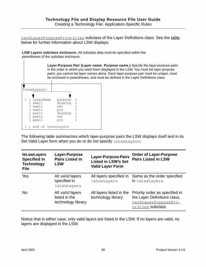
Technology File and Display Resource File User GuideCreating a Technology File: Application-Specific Rules
techLayerPurposePriorities subclass of the Layer Definitions class. See the tablebelow for further information about LSW displays.
The following table summarizes which layer-purpose pairs the LSW displays itself and in itsSet Valid Layer form when you do or do not specify leLswLayers :
Notice that in either case, only valid layers are listed in the LSW. If no layers are valid, nolayers are displayed in the LSW.
leLswLayersSpecified inTechnologyFile
Layer-PurposePairs Listed inLSW
Layer-Purpose PairsListed in LSW’s SetValid Layer Form
Order of Layer-PurposePairs Listed in LSW
Yes All valid layersspecified inleLswLayers
All layers specified inleLswLayers
Same as the order specifiedin leLswLayers
No All valid layerslisted in thetechnology library
All layers listed in thetechnology library
Priority order as specified inthe Layer Definitions class,techLayerPurposePri-orities subclass
Layer-Purpose Pair (Layer name. Purpose name.) Specify the layer-purpose pairsin the order in which you want them displayed in the LSW. You must list layer-purposepairs; you cannot list layer names alone. Each layer-purpose pair must be unique, mustbe enclosed in parentheses, and must be defined in the Layer Definitions class.
leLswLayers(
; ( layerName purpose )( nwell drawing )( nwell net )( nwell pin )( pwell drawing )( pwell net )( pwell pin )
) ; end of leLswLayers
LSW Layers subclass enclosure. All subclass data must be specified within theparentheses of the subclass enclosure.
April 2001 98 Product Version 4.4.6

Technology File and Display Resource File User GuideCreating a Technology File: Application-Specific Rules
Note: While the technology file entries determine the default LSW layer display, the LSWitself provides commands that let you modify whether layers are selectable and visible as youwork.
For more information about the leLswLayers subclass, refer to the Technology File andDisplay Resource File SKILL Reference Manual.
Virtuoso XL Rules
You use the Virtuoso layout accelerator (Virtuoso XL) with the layout editor to generatecustom layouts from schematics or to edit layouts that have defined connectivity. Virtuoso XLcontinuously monitors connections between components in the layout and compares themwith connections in the schematic. Virtuoso XL uses an online “extractor” to monitor the layersin a design and identify shorts in connectivity by looking for layers that cannot overlap. Youuse Virtuoso XL to view incomplete nets, shorts, invalid connections, and illegal overlaps inyour design.
You specify Virtuoso XL rules to provide the information Virtuoso XL needs to monitor theconnectivity in a layout. Virtuoso XL rules specify the following types of information:
■ Routing layers you want Virtuoso XL to monitor
■ Layers that cannot overlap in a design
You must set the Virtuoso XL rules in the technology file before you can use the tool toconnect the elements of a design.
For more information about Virtuoso XL, refer to the Virtuoso Layout Accelerator UserGuide.
April 2001 99 Product Version 4.4.6

Technology File and Display Resource File User GuideCreating a Technology File: Application-Specific Rules
Sample Virtuoso XL Rules Class
The following sample Virtuoso XL Rules class illustrates the class and its subclasses(sections), along with the Virtuoso XL rules they define.
Specifying Virtuoso XL Rules
Virtuoso XL Rules are required when you are using Virtuoso XL. As illustrated in the sample,the class must be specified by enclosing the subclass definitions within the lxRules() classenclosure. The following paragraphs provide detailed information about specifying subclassdata.
For more information about the lxRules class, refer to the Technology File and DisplayResource File SKILL Reference Manual.
lxRules(
lxExtractLayers(
; layer...
pwell ndiff pdiff poly1 cont metal1via metal2 (metal1 drawing1)(metal2 drawing1) via2 metal3
) ;end of lxExtractLayers
lxNoOverlapLayers(
; ( layer1 layer2 )
( poly1 ndiff )( poly1 pdiff )( via via2 )( metal2 drawing1 )
) ; end of lxNoOverlapLayers
lxMPPTemplates(
; ( t_mppTemplateName l_template )...
) ;end of lxMPPTemplates
) ; end of lxRules
Virtuoso XL Rules class enclosure.Place anywhere after the Layer Definitionsclass; usually follows the Layout EditorRules class. All subclasses must bespecified within the parentheses of theclass enclosure.
Extract Layers subclass. Lists layers forthe online extractor to monitor. All extractlayer data must be contained within theparentheses of the subclass enclosure.
No Overlap Layers subclass. Listslayers that cannot overlap in a Virtuoso XLdesign. Must follow lxExtractLayers .Layers listed here must also be listed inlxExtractLayers . All no overlap layerdata must be contained within theparentheses of the subclass enclosure.
MPP Templates subclass. Defines RODmultipart path templates. All templatedefinitions must be contained within theparentheses of the subclass enclosure.
End of Virtuoso XL Rules classenclosure. All subclasses must be insidethe parentheses of the class enclosure.
April 2001 100 Product Version 4.4.6

Technology File and Display Resource File User GuideCreating a Technology File: Application-Specific Rules
Specifying Extract Layers Rules: lxExtractLayers()
The lxExtractLayers subclass (section) of the Virtuoso XL Rules class specifies whichlayers in your design are to be monitored by the online extractor.
For more information about the lxExtractLayers subclass, refer to the Technology Fileand Display Resource File SKILL Reference Manual.
lxExtractLayers(
; ( layer... )
( pwell ndiff pdiff poly1 cont metal1 via metal2(metal1 drawing1) (metal2 drawing1) via2 metal3 )
) ; end lxExtractLayers
Extract Layers subclass enclosure. All subclass data must be specified within theparentheses of the subclass enclosure.
Layer names. Specify the layer name or layer-purpose pair (enclosed in parentheses) foreach layer to be monitored by the online extractor. Listing just the layer name forces theextractor to monitor all layer-purpose pairs with that layer name. Layer-purpose pairs mustalready be defined in the Layer Definitions class. The entire list of layer names must beenclosed in parentheses.
April 2001 101 Product Version 4.4.6

Technology File and Display Resource File User GuideCreating a Technology File: Application-Specific Rules
Specifying No Overlap Layers Rules: lxNoOverlapLayers()
The lxNoOverlapLayers subclass (section) of the Virtuoso XL Rules class specifies thelayers in your design that cannot overlap.
For more information about the lxNoOverlapLayers subclass, refer to the TechnologyFile and Display Resource File SKILL Reference Manual.
lxNoOverlapLayers(
; ( layer1 layer2 )
( poly1 ndiff )( poly1 pdiff )( via via2 )( metal2 drawing1 )
) ; end of lxNoOverlapLayers
No Overlap Layers subclass enclosure. All subclass data must be specified withinthe parentheses of the subclass enclosure.
Layer name 1. Specify the layer name or layer-purpose pair (enclosed inparentheses) for the first of two layers that cannot overlap. The layer must also belisted in lxExtractLayers . Each pair of layers must be separated by a space andenclosed in parentheses.
Layer name 2. Specify the layer name or layer-purpose pair (enclosed inparentheses) for the second of two layers that cannot overlap. The layer must also belisted in lxExtractLayers . Each pair of layers must be separated by a space andenclosed in parentheses.
April 2001 102 Product Version 4.4.6

Technology File and Display Resource File User GuideCreating a Technology File: Application-Specific Rules
Specifying Multipart Path Templates: lxMPPTemplates()
The lxMPPTemplates subclass (section) of the Virtuoso XL Rules class defines a templateor series of templates for relative object design (ROD) multipart paths (MPPs). A multipartpath is a single ROD object consisting of one or more parts at level zero in the hierarchy onthe same or on different layers. The purpose of an MPP template is to let you create MPPsin layout cellviews using predefined values. You can define any number of MPP templates inthe lxMPPTemplates subclass.
For more information about the lxMPPTemplates subclass, refer to the Technology Fileand Display Resource File SKILL Reference Manual.
Virtuoso Compactor Rules
You use the Virtuoso compactor to optimize symbolic designs by packing symbolic objects asclosely as possible. The compactor also helps you create layouts that adhere to design andelectrical rules.
You specify compactor rules to provide the information the compactor needs to optimize alayout. Compactor rules specify the following types of information:
■ Layer usage with the compactor
■ Symbolic wires and associated constraints that you use in your designs
■ Design rules that control compactor functions
For more information about the compactor, refer to the Virtuoso Compactor ReferenceManual.
lxMPPTemplates(
; ( t_mppTemplateName l_template)
) ;end lxMPPTemplates
MPP Templates subclass enclosure. All subclass data must be specified within theparentheses of the subclass enclosure.
MPP template name. Specify a unique name for the MPP template being defined.
Template definition lists. Specify master path arguments and, optionally, offsetsubpath arguments, enclosure subpath arguments, and/or subrectangle arguments.These arguments are based on the arguments for the rodCreatePath function.For details, see lxMPPTemplates in the Technology File and Display ResourceFile SKILL Reference Manual and the rodCreatePath section of the VirtuosoRelative Object Design User Guide.
April 2001 103 Product Version 4.4.6

Technology File and Display Resource File User GuideCreating a Technology File: Application-Specific Rules
Sample Compactor Rules Class
The following sample Compactor Rules class illustrates the class and its subclasses(sections), along with the compactor rules they define:
symWires(
; (name ( layer purpose)( PDIFF ( "diff" "drawing")
; [( impLayer impSpacing )]( ("implant" "drawing") 0.2 )
; [( defaultW minW maxW )]( 0.6 nil nil )
; [( regionName regionLayer )] [WLM] )( "inside" ( "nwell" "drawing" ) ) 100.0 )
.
.
.) ; end of symWires
compactorRules(
compactorLayers(; ( layer usage )
( diff “diffusion” )( poly1 “conduction” )
.
.
.( bndry “cellBoundary” )
) ; end of compactorLayers
symRules(
; ( drc; ( layer1 [ purpose1 [cell1] [view1]]]
( drc( "pimplant" "drawing" "PTAP" schematic )
; [( layer2 [ purpose2 [cell2] [view2]]]]( "diff" "drawing" "NTR" schematic)
; ( ruleType < value) [ modifier1 ] [ modifier2 ]( sep < 0.900000) "sameNet" "vertical"
.
.
.) ;end symRules
) ;end of compactorRules
Compactor Rules class enclosure.Place anywhere after the Devices class (it istypically placed after the Layout Editor Rulesclass) and before the LAS Rules class. Allsubclasses must be specified within theparentheses of the class enclosure.
Compactor Layers subclass. Listslayers and specifies how the compactor isto use them. All layer data must becontained within the parentheses of thesubclass enclosure.
Wires subclass. Defines the wiresused in your design. Used by thecompactor and the layout synthesizer.All wire data must be contained withinthe parentheses of the subclassenclosure.
End of Compactor Rules class enclosure. All subclassesmust be inside the parentheses of the class enclosure.
Compactor DesignRules subclass. Listsdesign rules thecompactor follows when itcompacts your design.This subclass is usuallylocated at the end of theCompactor Rules class.All compactor design ruledata must be containedwithin the parentheses ofthe subclass enclosure.
April 2001 104 Product Version 4.4.6

Technology File and Display Resource File User GuideCreating a Technology File: Application-Specific Rules
Specifying Compactor Rules
Compactor Rules are required when you are using the Virtuoso compactor. As illustrated inthe sample, the class must be specified by enclosing the subclass definitions within thecompactorRules() class enclosure. The following paragraphs provide detailed informationabout specifying subclass data.
For more information about the compactorRules class, refer to the Technology File andDisplay Resource File SKILL Reference Manual.
Specifying Compactor Layer Usage: compactorLayers()
The compactorLayers subclass (section) of the Compactor Rules class specifies how thecompactor treats layers in your design.
For more information about the compactorLayers subclass, refer to the Technology Fileand Display Resource File SKILL Reference Manual. For more information about thelayer usage selected by the keywords, refer to the Virtuoso Compactor ReferenceManual.
compactorLayers(
; ( layer usage )
( diff "diffusion" )( poly1 "conduction" )( metal "conduction" )( metal2 "conduction" )( metal3 "conduction" )( ( via pin ) "via" )( ( via2 pin ) "via" )( pwell "well" )( pimplant "implant" )( hardFence "hardfence" )( softFence "softfence" )( prBoundary "cellBoundary" )
) ;end of compactorLayers
Compactor Layers subclass enclosure. All subclass data must be specified withinthe parentheses of the subclass enclosure.
Layer name. Specify the layer name or layer-purpose pair (enclosed in parentheses) forthe layer for which you are defining the compactor usage. Each layer specified must bedefined in the Layer Definitions class.
Usage. Specify the keyword indicating the compactor usage of the layer.The following are the legal keywords:
diffusion softfence implant wellconduction hardfence via cellBoundary
April 2001 105 Product Version 4.4.6

Technology File and Display Resource File User GuideCreating a Technology File: Application-Specific Rules
Defining Symbolic Wires: symWires()
The compactor can stretch and insert jogs in the wires or paths in a layout design. You mustdefine the wires in the technology file so the Compactor knows which wire to use. LAS alsouses these wires to generate layouts.
When defining symWires , you must specify a layer name and purpose, for which you canapply the following optional constraints to the wire:
■ Implant layer and enclosure spacing
■ Width settings: minimum, maximum, or default
■ Legal region
■ Wire length minimization weight
The symWires subclass (section) of the Compactor Rules class defines wires for thecompactor.
April 2001 106 Product Version 4.4.6

Technology File and Display Resource File User GuideCreating a Technology File: Application-Specific Rules
symWires(
; (name ( layer purpose) [ (impLayer impSpacing)]( PDIFF ( "diff" "drawing") (("implant" "drawing") 0.2 )
; [( defaultW minW maxW )]( 0.6 nil nil )
; [( regionName regionLayer )] [WLM] )( "inside" ( "nwell" "drawing" ) ) 100.0 )
.
.
.) ;end symWires
Wires subclass enclosure. All subclass data must be specifiedwithin the parentheses of the subclass enclosure.
Wire name. Specify the name of the wire to update or create.
Layer-Purpose Pair (Layer name. Purpose name.). Specifythe name of the layer for the wire, followed by its purpose.Thelayer-purpose pair must be enclosed in parentheses.
Implant layer name. Specify the name of the implantlayer or layer-purpose pair (enclosed in parentheses) towhich to apply the constraint. Default purpose: drawing .
Implant layer constraints. You must specify these constraintsor, to define wire width data without defining implant data, specifynil . To specify implant layer constraints, specify the implantlayer and spacing as defined in the following:
Implant spacing. Specify the distance,in user units, by which the implant layermust enclose the wire layer.
Note: Continued infollowing figure.
April 2001 107 Product Version 4.4.6

Technology File and Display Resource File User GuideCreating a Technology File: Application-Specific Rules
symWires(
; (name ( layer purpose) [ (impLayer impSpacing)]( PDIFF ( "diff" "drawing") (("implant" "drawing") 0.2 )
; [( defaultW minW maxW )]( 0.6 nil nil )
; [( regionName regionLayer )] [WLM] )( "inside" ( "nwell" "drawing" ) ) 100.0 )
.
.
.) ;end symWires
Default width. Specify the default wire width, in user units.
Minimum width. Specify the minimum allowable wire width, in user units.Default: 0.
Maximum width. Specify the maximum allowable wire width, in user units.Default: infinity.
Wire width specifications. You must specify, in parentheses, avalue for at least one of the following widths, in user units (for anyparameter for which you specify no value, you must specify nil ):
Note: Continued infollowing figure.
April 2001 108 Product Version 4.4.6

Technology File and Display Resource File User GuideCreating a Technology File: Application-Specific Rules
For more information about the symWires subclass, refer to the Technology File andDisplay Resource File SKILL Reference Manual. For more information about the optionsyou specify, refer to the Virtuoso Compactor Reference Manual.
Setting Design Rules for Compaction: symRules
Design rules specific to compactor functions differ from Physical Rules in that you can restrictrules to objects on the same net or on different nets, or to layers on specific devices or pcells.
You can specify the following constraints to control design compaction:
■ Minimum distance between outside facing edges of two objects on the same layer
■ Minimum distance between outside facing edges of two objects on different layers
■ Minimum enclosure distance between objects on different layers
The symRules subclass (section) of the Compactor Rules class defines design rules for thecompactor.
symWires(
; (name ( layer purpose) [ (impLayer impSpacing)]( PDIFF ( "diff" "drawing") (("implant" "drawing") 0.2 )
; [( defaultW minW maxW )]( 0.6 nil nil )
; [( regionName regionLayer )] [WLM] )( "inside" ( "nwell" "drawing" ) ) 100.0 )
.
.
.) ;end symWires
Legal region. To define the legal region, specify the region name and region layer asdefined in the following:
Weighting. Specify the weighting, as any positivenumber, indicating the relative priority to thecompactor for minimizing the length of the wire.
Legal region name. Specify the legal region, either inside or outside .
Legal region layer. Specify the layer name or layer-purpose pair (enclosed inparentheses) for the layer that is the object of the legal region layer. Default: drawing .
April 2001 109 Product Version 4.4.6

Technology File and Display Resource File User GuideCreating a Technology File: Application-Specific Rules
symRules(
; ( drc; ( layer1 [ purpose1 [cell1] [view1]]]
( drc( "pimplant" "drawing" "PTAP" schematic)
; [( layer2 [ purpose2 [cell2] [view2]]]]( "diff" "drawing" "NTR" schematic)
; ( ruleType < value) [ modifier 1 ] [ modifier2 ]( sep < 0.900000) "sameNet" "vertical"
.
.
.) ;end symRules
Compactor Design Rules subclass enclosure. All subclass data must be specifiedwithin the parentheses of the subclass enclosure.
drc. Always specify the keyword drc to indicate that design rules follow.
Cell name. Specify the name of the master cell of the component.
View name. Specify the view name of the component. If youspecify a cell name but no view name, the default is symbolic .
Second layer data. Theparameters for the second layer areidentical to those for the first layer.If not specified, the rule applies toobjects drawn on the same layerand instances of the same device.
Layer name. Specify the layer name for the layer for which you are defining thecompactor rule. Each layer specified must be defined in the Layer Definitionsclass and must be assigned a compactor keyword in the
Purpose name. Specify the purpose for the layer for which you are defining theCompactor rule. If you specify a cell and view, you must specify a layer purpose.
compactorLayers subclass.
Note: Continued infollowing figure.
April 2001 110 Product Version 4.4.6

Technology File and Display Resource File User GuideCreating a Technology File: Application-Specific Rules
For more information about the symRules subclass, refer to the Technology File andDisplay Resource File SKILL Reference Manual.
symRules(
; ( drc; ( layer1 [ purpose1 [cell1] [view1]]]
( drc( "pimplant" "drawing" "PTAP" schematic)
; [( layer2 [ purpose2 [cell2] [view2]]]]( "diff" "drawing" "NTR" schematic)
; ( ruleType < value) [ modifier 1 ] [ modifier2 ]( sep < 0.900000) "sameNet" "vertical"
.
.
.) ; end of symRules
Value. Specify the minimum separation or enclosure distanceallowed or the keyword dontcare .
Modifier1. Specify a modifier (sameNet or diffNet )to place a restriction on the rule.
Modifier2. Specify a modifier(horizontal or vertical ) to placea restriction on the rule.
Rule type. Specify the type of rule, either separation (sep ) or enclosure (enc ).
April 2001 111 Product Version 4.4.6

Technology File and Display Resource File User GuideCreating a Technology File: Application-Specific Rules
Virtuoso Layout Synthesizer (LAS) Rules
You use the Virtuoso layout synthesizer (LAS) to generate uncompacted physical layoutsfrom schematics, transistor netlists, or autoLayout views. You can do the following with LAS:
■ Generate layouts from hierarchical circuits that can be flattened to the level of individualtransistors
■ Build customized cells and digital random logic blocks
■ Create standard cells for standard cell libraries and datapath libraries
You specify layout synthesizer rules to define the layers, wires, devices, and specialproperties LAS uses to generate layout designs. You must set the layout synthesizer rules inthe technology file before you can use LAS to generate layout designs.
For more information about the Virtuoso layout synthesizer, refer to the Virtuoso LayoutSynthesizer User Guide.
April 2001 112 Product Version 4.4.6

Technology File and Display Resource File User GuideCreating a Technology File: Application-Specific Rules
Sample Layout Synthesizer Rules Class
The following sample Layout Synthesizer Rules class illustrates the class and its subclasses(sections), along with the rules they define:
lasRules(
lasLayers(
; ( layer usage )( ndiff "ndiffLayer" )( pdiff "pdiffLayer" )( pwell "pwellLayer" )( poly1 "polyLayer" )( metal1 "met1Layer" )( metal2 "met2Layer" )
.
.
.( metal3 "met3Layer" )
) ; end of lasLayers
lasDevices(; ( cellview LASDevName )
( (NTR symbolic) "ntr" )( (PTR symbolic) "ptr" )( (M1_P symbolic) "pd_m1" )( (M1_N symbolic) "nd_m1" )( (M1_POLY1 symbolic) "poly_m1" )( (M1_M2 symbolic) "m1_m2" )( (PTAP symbolic) "psub_m1" )( (NTAP symbolic) "nsub_m1" )( (poly1_T symbolic) "poly_pin" )( (metal1_T symbolic) "m1_pin" )( (metal2_T symbolic) "m2_pin" )
) ; end of lasDevices
lasWires(
; ( wireName wireType )( "ndiff" "ndiffWire" )( "pdiff" "pdiffWire" )
.
.
.) ; end of lasWires
Layout Synthesizer Rules classenclosure. Must be placed anywhereafter the Compactor Rules class. Allsubclasses must be specified within theparentheses of the class enclosure.
LAS Layers subclass. Lists layers andhow LAS uses them. Data for each layermust be enclosed in parentheses. All layerspecifications must be enclosed within theparentheses of the subclass enclosure.
LAS Devices subclass. Lists thedevices LAS uses when it automaticallysynthesizes a design. Specifies cell, view,and LAS device name. Data for eachcellview must be enclosed in parentheses,and the cellview and device name must bewithin parentheses. All LAS devicespecifications must be enclosed within theparentheses of the subclass enclosure.
LAS Wires subclass. Lists wires andhow LAS uses them. Data for each wiremust be enclosed in parentheses. All wirespecifications must be enclosed within theparentheses of the subclass enclosure.
April 2001 113 Product Version 4.4.6

Technology File and Display Resource File User GuideCreating a Technology File: Application-Specific Rules
Specifying Layout Synthesizer Rules
Layout synthesizer rules are required when you are using the Virtuoso layout synthesizer. Asillustrated in the sample, the class must be specified by enclosing the subclass definitionswithin the lasRules() class enclosure. The following paragraphs provide detailedinformation about specifying subclass data.
For more information about the lasRules class, refer to the Technology File and DisplayResource File SKILL Reference Manual.
Specifying Layer Usage: lasLayers()
LAS creates and routes devices when it generates a layout. To accomplish this, LAS needsto know which layers you want it to use and how you want it to use them.
The lasLayers subclass (section) of the Layout Synthesizer Rules class specifies how LAStreats layers in your design.
lasProperties(; ( propName propValue )
( "lasSwitchViewList" "schematic symbolic" )( "lasPrimitiveList" "pmos nmos PTR NTR
HPTR HNTF" )( "lasPseudoElementList" "vdd gnd ndiff_T
pdiff_T poly2_T" )( "lasNSpiceCellView" "nmos cdl" )( "lasPSpiceCellView" "pmos cdl" )( "lasMfactorSplit" nil )( "lasNetlistNtr" "hnmos nmos" )( "lasNetlistPtr" "hpmos pmos" )( lasLayoutNtr" "HNTR NTR" )( "lasLayoutPtr" "HPTR PTR" )
) ; end of lasProperties
) ; end of lasRules
LAS Properties subclass.Lists the properties LAS uses tocontrol how it synthesizes adesign. Specifies propertynames and values. All LASproperty specifications must beenclosed within the parenthesesof the subclass enclosure.
End of Layout SynthesizerRules class enclosure. Allsubclasses must be inside theparentheses of the classenclosure.
April 2001 114 Product Version 4.4.6

Technology File and Display Resource File User GuideCreating a Technology File: Application-Specific Rules
The following table lists all of the LAS layer keywords. In some cases, you can use analternative generic keyword instead of the more specific primary keyword.
For more information about the lasLayers subclass, refer to the Technology File andDisplay Resource File SKILL Reference Manual.
LAS Usage Layer Keyword AlternativeKeyword
Diffusion ndiffLayer , pdiffLayer diffLayer
Well nwellLayer , pwellLayer
Poly polyLayer
Metal met1Layer , met2Layer , met3Layer
Metal1 powerand ground
met1PowerLayer ,met1GroundLayer
met1PGLayer
Metal2 powerand ground
met2PowerLayer ,met2GroundLayer
met2PGLayer
Ring nringLayer , pringLayer ringLayer
lasLayers(
; ( layer usage )
( ndiff "ndiffLayer" )( pdiff "pdiffLayer" )( pwell "pwellLayer" )( poly1 "polyLayer" )( metal1 "met1Layer" )( ( metal1 drawing2 ) "met1PGLayer" )( ( via2 pin ) "via" )( metal2 "met2Layer" )( pimplant "implant" )
) ; end of lasLayers
LAS Layers subclass enclosure. All subclass data must bespecified within the parentheses of the subclass enclosure.
Layer name. Specify the layer name or layer-purpose pair (enclosed in parentheses) for the layer forwhich you are defining LAS usage. Each layer specified must be defined in the Layer Definitions class.
Usage. Specify the keyword indicating the LAS usage of the layer.See the table following this figure for the LAS layer keywords.
April 2001 115 Product Version 4.4.6

Technology File and Display Resource File User GuideCreating a Technology File: Application-Specific Rules
Specifying Devices That Can Be Placed: lasDevices()
LAS often needs to place instances of devices in a generated design. To accomplish this, LASneeds to know which device cellviews to place.
The lasDevices subclass (section) of the Layout Synthesizer Rules class specifies devicecellviews for LAS to use in your design.
The following table lists all of the LAS device keywords. In some cases, you can use analternative generic keyword instead of the more specific primary keyword.
LAS Usage Device Keyword AlternativeKeyword
MOS transistors ntr , ptr
Required pins poly_pin , m1_pin , pd_m1,nd_m1, poly_m1
Optional pins m2_pin , m3_pin
Special-purpose pins nring_pin , pring_pin ring_pin
lasDevices(
; ( cellview LAS name )
( ( NTR symbolic ) "ntr" )( ( PTR symbolic ) "ptr" )( ( M1_P symbolic ) "pd_m1" )( ( M1_N symbolic ) "nd_m1" )( ( M1_POLY1 symbolic ) "poly_m1" )( ( M1_M2 symbolic ) "m1_m2" )( ( PTAP symbolic ) "psub_m1" )( ( poly1_T symbolic ) "poly_pin" )( ( metal1_T symbolic ) "m1_pin" )( ( metal2_T symbolic ) "m1_pin" )
) ; end of lasDevices
LAS Devices subclass enclosure. All subclass data must be specifiedwithin the parentheses of the subclass enclosure.
Cellview. Specify the device name and view, separated by a space and enclosed inparentheses. Each device specified must be defined in the Devices class.
LAS name. Specify the keyword indicating the LAS name of the device.See the table following this figure for the LAS device keywords.
April 2001 116 Product Version 4.4.6

Technology File and Display Resource File User GuideCreating a Technology File: Application-Specific Rules
For more information about the lasDevices subclass, refer to the Technology File andDisplay Resource File SKILL Reference Manual.
Specifying Wires for LAS Use: lasWires()
LAS places implant and ring wires when it generates a layout design. To place wires, LASneeds to know which wires you want to use for what purpose.
The lasWires subclass (section) of the Layout Synthesizer Rules class defines the wires forLAS to use in your design.
Required contacts nd_m1, pd_m1, poly_m1 ,nsub_m1 , psub_m1
Optional contacts m1_m2, m2_m3
Special-purpose contacts po_np , po_pp , n_p1_m1,p_p1_m1, nm1_leak , pm1_leak
p1_p2 ,p1_m1
LAS Usage Device Keyword AlternativeKeyword
lasWires(
; ( wireName wireType )
( "ndiff" "ndiffWire" )( "pdiff" "pdiffWire" )
.
.
.
) ; end of lasWires
LAS Wires subclass enclosure. All subclass data must be specifiedwithin the parentheses of the subclass enclosure.
Wire name. Specify the wire name. Each wire specified must be defined in thesymWires subclass of the Compactor Rules class.
Wire type. Specify the keyword indicating the LAS wire type. See the tablefollowing this figure for the LAS wire keywords.
April 2001 117 Product Version 4.4.6

Technology File and Display Resource File User GuideCreating a Technology File: Application-Specific Rules
The following table lists the LAS wire keywords. In some cases, you can use an alternativegeneric keyword instead of the more specific primary keyword.
For more information about the lasWires subclass, refer to the Technology File andDisplay Resource File SKILL Reference Manual.
Specifying LAS Properties: lasProperties()
LAS provides properties that you can set to control how it generates a layout.
The lasProperties subclass (section) of the Layout Synthesizer Rules class specifies theproperties for LAS to use in your design.
LAS Usage Wire Keyword AlternativeKeyword
Diffusion implant wires ndiffWire , pdiffWire diffWire
Guard ring wires nringWire , pringWire ringWire
lasProperties(
; ( propName propValue )
( "lasSwitchViewList" "schematic symbolic" )( "lasPrimitiveList" "pmos nmos PTR NTR HPTR HNTR" )( "lasPseudoElementList" "vdd gnd ndiff_T pdiff_T poly2_T )( "lasNSpiceCellView" "nmos cdl" )( "lasPSpiceCellView" "pmos cdl" )( "lasMfactorSplit" nil )( "lasNetlistNtr" "hnmos nmos" )( "lasNetlistPtr" "hpmos pmos" )( "lasLayoutNtr" "HNTR NTR" )( "lasLayoutPtr" "HPTR PTR" )
) ; end of lasProperties
LAS Properties subclass enclosure. All subclass data must be specifiedwithin the parentheses of the subclass enclosure.
Property value. Specify the string value, enclosed in doublequotation marks, for the property.
Property name. Specify the property name, enclosed in double quotation marks, from thelist of LAS-provided properties shown in the table following this figure.Property name. Specify the property name, enclosed in double quotation marks, from thelist of LAS-provided properties shown in the table following this figure.
April 2001 118 Product Version 4.4.6

Technology File and Display Resource File User GuideCreating a Technology File: Application-Specific Rules
The following table lists the LAS-provided properties and their types and default values.
Valid LAS Property Name Data-type Default Value
lasBulkNameList String "B b BULK Bulk bulk"
lasDrainNameList String "D d DRAIN Drain drain"
lasGateNameList String "G g GATE Gate gate"
lasInstTypePropName String "subtype"
lasLayoutNtr String
lasLayoutPtr String
lasLengthName String "l"
lasMasterTypePropName String "instNamePrefix"
lasMfactorName String "m"
lasMfactorSplit Boolean t
lasNSpiceCellView String
lasNetlistNtr String
lasNetlistPtr String
lasPSpiceCellView String
lasPrimitiveList String "mos pmos nmos pfet nfet"
lasPseudoElementList String "vdd gnd Asize Bsize CsizeASIZE BSIZE CSIZE"
lasReadCDFParam Boolean t
lasSourceNameList String "S s SOURCE Source source"
lasSwitchViewList String "schematic gate.sch cmos.schnetlist symbol symbolic"
lasVddName String
lasVddNameList String "||vdd! |vdd! vdd! VCC VDD PWRvdd vcc pwr"
lasVssName String
lasVssNameList String "||gnd! |gnd! gnd! VSS GNDGROUND GRND vss gnd"
April 2001 119 Product Version 4.4.6

Technology File and Display Resource File User GuideCreating a Technology File: Application-Specific Rules
For more information about the lasProperties subclass, refer to the Technology Fileand Display Resource File SKILL Reference Manual.
Place and Route Rules
You use the place-and-route tools to perform design place and route functions as follows:
■ Preview Silicon Ensemble™ software performs layout for very large standard cell-based integrated circuits. It supports two- through six-layer routing.
■ Preview Gate Ensemble® software performs place and route functions for gate arraydesign.
You specify Place and Route Rules to provide the information the place-and-route tools needto optimize a layout. Place and Route Rules specify the following types of information:
■ Routing layers and their order of placement
■ Devices used as vias and the rules that apply to them
■ Stackable contact vias
■ Master slice layers
■ Rules for placing vias
■ Rules for generating vias
■ Rules for closing gaps on 90-degree turns on via layers
■ Rules for routing with nondefault wire widths
■ Minimum allowable spacing between geometries on different nets
■ Distance between placement and routing grids
■ Overlap boundaries, where cells cannot overlap
For more information about the Preview place-and-route tools, refer to the following manuals:
■ Preview Silicon Ensemble Reference
■ Preview Gate Ensemble Reference
lasWidthName String "w"
Valid LAS Property Name Data-type Default Value
April 2001 120 Product Version 4.4.6

Technology File and Display Resource File User GuideCreating a Technology File: Application-Specific Rules
Sample Place and Route Rules Class
The following sample Place and Route Rules class illustrates the class and its subclasses(sections), along with the rules they define.
prRules(
prRoutingLayers(
; ( layer direction )( poly1 "vertical" )( metal1 "horizontal" )( metal2 "vertical" )( metal3 "horizontal" )
.
.
.) ; end of prRoutingLayers
prViaTypes(; ( (device cellViewName) viaType )
( (M2_M1 symbolic) "default" )( (M3_M2 symbolic) "default" )( (ND1M2_M1 symbolic) "NDrule1" )( (ND1M3_M2 symbolic) "NDrule1" )( (ND2M2_M1 symbolic) "NDrule2" )( (ND2M3_M2 symbolic) "NDrule2" )
.
.
.) ;end prViaTypes
prStackVias(
; ( layer... )( via via2 )( ( poly1 drawing ) poly2 )
) ; end of prStackVias
prMastersliceLayers(; ( layer... )
( diff poly1 )
) ;end prMastersliceLayers
Place and Route Rules classenclosure. Must be placed anywhere afterthe Devices class. All subclasses must bespecified within the parentheses of the classenclosure.
Routing Layers subclass. Lists routinglayers in the order of placement, with layersclosest to the substrate listed first. Data foreach layer must be enclosed inparentheses. All layer specifications mustbe enclosed within the parentheses of thesubclass enclosure.
Via Types subclass. Lists the devices thatthe place and route tools use as vias; alsospecifies the rules that apply to the devices.Data for each device must be enclosed inparentheses, and the device name andcellview must be within parentheses. All viatype specifications must be enclosed withinthe parentheses of the subclass enclosure.
Stack Vias subclass. Lists pairs ofcontact via layers that can be stacked inPreview Gate Ensemble software andSilicon Ensemble software. The list of layersmust be enclosed in parentheses. All stacklayer data must be enclosed within theparentheses of the subclass enclosure.
Master Slice Layers subclass. Listsmaster slice layers, from lowest to highest,for use by Preview Gate Ensemble softwareand Silicon Ensemble software. The list oflayers must be enclosed in parentheses. Allmaster slice layer data must be enclosedwithin the parentheses of the subclassenclosure.
April 2001 121 Product Version 4.4.6

Technology File and Display Resource File User GuideCreating a Technology File: Application-Specific Rules
prViaRules(; ( ruleName viaName; layer1 dir1 ( wMin wMax overhang metalOverHang ); layer2 dir2 ( wMin wMax overhang metalOverhang )
( "viaSP21" (M2_M1)metal1 "vertical" ( .6 1.8 _NA_ _NA_)metal2 "horizontal" ( .6 1.8 _NA_ _NA_ ) )
.
.
.) ; end of prViaRules
Via Placement Rules subclass. Defines rules for placing vias with SROUTE or thePreview PowerRoute options of Preview Gate Ensemble software and Preview SiliconEnsemble software. Each rule definition must be enclosed in parentheses and liststhe rule name, the list of devices to use, and the routing situation of the two routinglayers. All rule data must be within the parentheses of the subclass enclosure.
Via Generation Rules subclass. Defines rules for generating vias with SROUTEor the Preview PowerRoute options of Preview Gate Ensemble software and PreviewSilicon Ensemble software. Each rule definition must be enclosed in parentheses andlists the rule name, the dimensions of the via to create, and the routing situation of thetwo routing layers. All rule data must be within the parentheses of the subclassenclosure.
Turn Via Rules subclass. Defines rules for closing a gap on a 90-degree turn ona via layer when placing with SROUTE or the Preview PowerRoute options of PreviewGate Ensemble software and Preview Silicon Ensemble software. Each rule definitionmust be enclosed in parentheses. All rule data must be enclosed within theparentheses of the subclass enclosure.
prGenViaRules(; ( ruleName layer; ( width length xPitch yPitch resistance ); layer1 dir1 ( wMin wMax overhang metalOverHang ); layer2 dir2 ( wMin wMax overhang metalOverhang )
( viagen21 via( .6 .6 1.2 1.2 _NA_ )
metal1 "horizontal" ( .6 2.0 .6_ .6 )metal2 "vertical" ( .6 2.0 .6 .6 ) )
.
.
.) ; end of prGenViaRules
prTurnViaRules(
; ( ruleName layer ( directionList ) )( "TURN1" metal1 ("vertical" "horizontal" ) )( "TURN2" metal2 ("vertical" "horizontal" ) )( "TURN3" metal3 ("vertical" "horizontal" ) )
) ; end of prTurnViaRules
April 2001 122 Product Version 4.4.6

Technology File and Display Resource File User GuideCreating a Technology File: Application-Specific Rules
prNonDefaultRules(; ( ruleName; ( ( layer width spacing [notch] ... ); ( ( viaName [resistance] ) ... ); [ ( ( layer1 layer2 minSpace stack ) ... ) ]
("NDrule1"( (metal1 3.8 1.5 1.3 )
( metal2 4.8 1.6 _NA_ )( metal3 4.8 1.6 _NA_ ) )
( ( ND1M2_M1 .8) (ND1M3_M2 .8) )( ( metal1 metal1 1.3 nil )
( via via2 4.5 nil ) )
) ; end of prNonDefaultRules
prRoutingPitch(
; ( layer pitch )( metal1 2.4 )( metal2 2.4 )
.
.
.) ; end of prRoutingPitch
prRoutingOffset(
; ( layer offset )( metal1 0.0 )( metal2 1.2 )
.
.
.) ; end of prRoutingOffset
prOverlapLayer(
; layeroverlap overlap2
) ; end of prOverlapLayer
) ; end of prRules End of Place and Route Rules classenclosure. All subclasses must be inside theparentheses of the class enclosure.
Overlap Layer subclass. Defines the overlap layer or layersused to display the overlap boundary for cells. The overlapboundary indicates where cells cannot overlap. The overlap layersspecified must be enclosed within the parentheses of the subclassenclosure.
Nondefault Rules subclass.Defines rules for routing withnondefault wire widths withSROUTE or the PreviewPowerRoute options of PreviewGate Ensemble software andPreview Silicon Ensemblesoftware. Each rule definitionmust be enclosed inparentheses. All rule data mustbe enclosed within theparentheses of the subclassenclosure.
Routing Pitch subclass. Used by Silicon Ensemblesoftware only. Defines the routing pitch (the minimum allowablespacing, center to center) between two regular geometries ondifferent nets. Data for each layer must be enclosed inparentheses. All routing pitch specifications must be enclosedwithin the parentheses of the subclass enclosure.
Routing Offset subclass. Used by Silicon Ensemblesoftware only. Defines the routing offset, or the distance betweenthe placement grid and the routing grid when there is a routing gridbetween two placement grids. Data for each layer must beenclosed in parentheses. All routing offset specifications must beenclosed within the parentheses of the subclass enclosure.
April 2001 123 Product Version 4.4.6

Technology File and Display Resource File User GuideCreating a Technology File: Application-Specific Rules
Specifying Place and Route Rules
Place and Route Rules are required when you are using the Preview place-and-route tools(Preview Silicon Ensemble and Preview Gate Ensemble). As illustrated in the sample, theclass must be specified by enclosing the subclass definitions within the prRules() classenclosure. The following paragraphs provide detailed information about specifying subclassdata.
For more information about the prRules class, refer to the Technology File and DisplayResource File SKILL Reference Manual.
Specifying Routing Layers: prRoutingLayers()
The prRoutingLayers subclass (section) of the Place and Route Rules class defines therouting direction of layers the place and route tools use for routing.
For more information about the prRoutingLayers subclass, refer to the Technology Fileand Display Resource File SKILL Reference Manual.
prRoutingLayers(
; ( layer direction )( poly1 "vertical" )( metal1 "horizontal" )( metal2 "vertical" )
.
.
.) ; end of prRoutingLayers
Routing Layers subclass enclosure. All subclass data must be specified within theparentheses of the subclass enclosure.
Direction. Specify the routing direction from the choices halfRoute ,vertical , or horizontal .
Layer name. Specify the layer name. For each layer you specify, the layer-purposepair with the purpose drawing must be defined in the Layer Definitions class.
April 2001 124 Product Version 4.4.6

Technology File and Display Resource File User GuideCreating a Technology File: Application-Specific Rules
Specifying Vias: prViaTypes()
The prViaTypes subclass (section) of the Place and Route Rules class defines the vias forthe place and route tools use during automatic routing.
For more information about the prViaTypes subclass, refer to the Technology File andDisplay Resource File SKILL Reference Manual.
prViaTypes(
; ( ( device cellViewName ) viaType )( ( M2_M1 symbolic ) "default" )( ( M3_M2 symbolic ) "default" )( ( ND1M2_M1 symbolic ) "NDrule1" )( ( ND1M3_M2 symbolic ) "NDrule1" )( ( ND2M2_M1 symbolic ) "NDrule2" )( ( ND2M3_M2 symbolic ) "NDrule2" )
.
.
.) ; end of prViaTypes
Via Types subclass enclosure. All subclass data must bespecified within the parentheses of the subclass enclosure.
Via type. Specify the name of the rule indicating how the placeand route tools are to use the device. Specify either default(selects default width routing for all tools) or a rule name definedin the prNonDefaultRules subclass.
Device name. Specify the device name. Each devicespecified must be defined in the Devices class.
Device name and cellview name. Specify thedevice name and cellview name, in parentheses andseparated by a space, as follows:
Cellview name. Specify the cellview name.
April 2001 125 Product Version 4.4.6

Technology File and Display Resource File User GuideCreating a Technology File: Application-Specific Rules
Specifying Vias That Can Be Stacked: prStackVias()
The prStackVias subclass (section) of the Place and Route Rules class defines the vialayers that can be stacked in Preview Gate Ensemble software and Preview Silicon Ensemblesoftware.
For more information about the prStackVias subclass, refer to the Technology File andDisplay Resource File SKILL Reference Manual.
prStackVias(
; ( layer... )( via via2 )( ( poly1 drawing ) poly2 )
) ; end of prStackVias
Stack Vias subclass enclosure. All subclass data must be specified within theparentheses of the subclass enclosure.
Layer names. Specify the names of the via layers that can be stacked, separated byspaces. A purpose of drawing is assumed. For each layer you specify, the layer-purposepair with the purpose drawing must be defined in the Layer Definitions class. Also, eachvia layer specified must be used in a contact or ruleContact device already specifiedin the Devices class.
April 2001 126 Product Version 4.4.6

Technology File and Display Resource File User GuideCreating a Technology File: Application-Specific Rules
Specifying Master Slice Layers: prMastersliceLayers()
The prMastersliceLayers subclass (section) of the Place and Route Rules class definesthe master slice layers for use in Preview Gate Ensemble software and Preview SiliconEnsemble software.
For more information about the prMastersliceLayers subclass, refer to the TechnologyFile and Display Resource File SKILL Reference Manual.
Specifying Via Rules: prViaRules()
The prViaRules subclass (section) of the Place and Route Rules class defines the rules forplacing vias using the SROUTE or the Preview PowerRoute options of Preview GateEnsemble software and Preview Silicon Ensemble software.
prMastersliceLayers(
; ( layer... )( diff poly1 )
.
.
.
) ; end of prMastersliceLayers
Master Slice Layers subclass enclosure. All subclass data must be specified withinthe parentheses of the subclass enclosure.
Layer names. Specify the names of the master slice layers in order, starting with the layerclosest to the substrate and progressing to the layer farthest from the substrate. Separate thelayer names by a space. A purpose of drawing is assumed. For each layer you specify, thelayer-purpose pair with the purpose drawing must be defined in the Layer Definitions class.
April 2001 127 Product Version 4.4.6

Technology File and Display Resource File User GuideCreating a Technology File: Application-Specific Rules
Note: The place-and-route software evaluates the rules and vias listed in this subclass foruse on a first-found, first-used basis. If you define more than one rule for a routing situation,the second rule will not be read.
prViaRules(
; ( ruleName viaName( "viaSP21" (M2_M1)
; layer1 dir1 ( wMin wMax overhang metalOverHang )metal1 "vertical" ( .6 1.8 _NA_ _NA_ )
; layer2 dir2 ( wMin wMax overhang metalOverhang )metal2 "horizontal" ( .6 1.8 _NA_ _NA_ ) )
.
.
.) ; end of prViaRules
Via Rules subclass enclosure. All subclass data must be specifiedwithin the parentheses of the subclass enclosure.
Via layer name. Specify the via or vias, enclosed in parentheses and separatedby spaces, that can be used. Each via specified must be a contact orruleContact device already defined in the Devices class.
Rule name. Specify any unique string.
Note: Continued infollowing figure.
April 2001 128 Product Version 4.4.6

Technology File and Display Resource File User GuideCreating a Technology File: Application-Specific Rules
The following sample illustrates the use of the prViaRules subclass:
prViaRules(
; ( ruleName viaName( "viaSP21" (M2_M1)
; layer1 dir1 ( wMin wMax overhang metalOverHang )metal1 "vertical" ( .6 1.8 _NA_ _NA_ )
; layer2 dir2 ( wMin wMax overhang metalOverhang )metal2 "horizontal" ( .6 1. _NA_ _NA_ ) )
) ; end of prViaRules
This code specifies that the router place the M2_M1 contact in the following situation:
prViaRules(
; ( ruleName viaName( "viaSP21" (M2_M1)
; layer1 dir1 ( wMin wMax overhang metalOverHang )metal1 "vertical" ( .6 1.8 _NA_ _NA_ )
; layer2 dir2 ( wMin wMax overhang metalOverhang )metal2 "horizontal" ( .6 1.8 _NA_ _NA_ ) )
.
.
.) ; end of prViaRules
Layer name. Specify the name of the routing layer for the top of thevia. A purpose of drawing is assumed. The layer-purpose pair withthe purpose drawing must be defined in the Layer Definitions class.
Maximum width. Specify the maximum allowable wirewidth, in user units.
Overhang. Specify the minimum spacing between thecontact cut and the outer edge of the via.
Metal overhang. Specify the minimum overhangof the via to the wire.
Direction. Specify the routing direction for the top routinglayer (horizontal or vertical ).
Minimum width. Specify the minimum allowable wire width, in user units.
Layer 2 specifications. Specify the same setof parameters for the layer for the bottom of thevia as for the layer for the top of the via.
April 2001 129 Product Version 4.4.6

Technology File and Display Resource File User GuideCreating a Technology File: Application-Specific Rules
■ The two layers that need a via are metal1 and metal2
■ Both paths have a width between 0.6 and 1.8 user units
■ The metal1 path is moving verticall.
■ The metal2 path is moving horizontally
■ The contact extends past the metal1 and metal2 paths by 0.6 user units
For more information about the prViaRules subclass, refer to the Technology File andDisplay Resource File SKILL Reference Manual.
Specifying Generated Via Rules: prGenViaRules()
A generated via rule specifies the dimensions of a via the router generates as it routes.
The prGenViaRules subclass (section) of the Place and Route Rules class defines thegenerated via rules.
prGenViaRules(
; ( ruleName layer( viagen21 via
; ( width length xPitch yPitch resistance )( .6 .6 1.2 1.2 _NA_ )
; layer1 dir1 ( wMin wMax overhang metalOverHang )metal1 "horizontal" ( .6 2.0 .6_ .6 )
; layer2 dir2 ( wMin wMax overhang metalOverhang )metal2 "vertical" ( .6 2.0 .6 .6 )
.
.
.) ;end prGenViaRules
Generated Via Rules subclass enclosure. All subclass data must bespecified within the parentheses of the subclass enclosure.
Via layer name. Specify the via or vias, enclosed in parentheses and separated byspaces, that can be used. Each via specified must be a contact or ruleContactdevice already defined in the Devices class.
Rule name. Specify any unique string for the rule name.
Note: Continued infollowing figure.
April 2001 130 Product Version 4.4.6

Technology File and Display Resource File User GuideCreating a Technology File: Application-Specific Rules
prGenViaRules(
; ( ruleName layer( viagen21 via
; ( width length xPitch yPitch resistance )( .6 .6 1.2 1.2 _NA_ )
; layer1 dir1 ( wMin wMax overhang metalOverHang )metal1 "horizontal" ( .6 2.0 .6_ .6 )
; layer2 dir2 ( wMin wMax overhang metalOverhang )metal2 "vertical" ( .6 2.0 .6 .6 )
.
.
.) ;end prGenViaRules
Note: Continued infollowing figure.
Width. Specify the width of the via layer.
y pitch. Specify the y pitch of the via layer.
Resistance. Specify the resistance of the via layer.
Length. Specify the length of the via layer.
x pitch. Specify the x pitch of the via layer.
April 2001 131 Product Version 4.4.6

Technology File and Display Resource File User GuideCreating a Technology File: Application-Specific Rules
The following sample illustrates the use of the prGenViaRules subclass:
prViaRules(...)
prGenViaRules(; ( viaRuleName; viaLayer ( width length xPitch yPitch resistance ); layer1 dir1 ( wMin wMax overhang metalOverhang ); layer2 dir2 ( wMin wMax overhang metalOverhang )
prGenViaRules(
; ( ruleName layer( viagen21 via
; ( width length xPitch yPitch resistance )( .6 .6 1.2 1.2 _NA_ )
; layer1 dir1 ( wMin wMax overhang metalOverhang )metal1 "horizontal" ( .6 2.0 .6_ .6 )
; layer2 dir2 ( wMin wMax overhang metalOverhang )metal2 "vertical" ( .6 2.0 .6 .6 )
.
.
.) ; end of prGenViaRules
Layer name. Specify the name of the routing layer for the top of thevia. A purpose of drawing is assumed. The layer-purpose pair with thepurpose drawing must be defined in the Layer Definitions class.
Maximum width. Specify the maximum allowablewire width, in user units.
Overhang. Specify the minimum spacing betweenthe contact cut and the outer edge of the via.
Metal overhang. Specify the minimumoverhang of the via to the wire.
Direction. Specify the routing direction for the toprouting layer (horizontal or vertical ).
Minimum width. Specify the minimum allowable wirewidth, in user units.
Layer 2 specifications. Specify the same setof parameters for the bottom routing layer as forthe top routing layer.
April 2001 132 Product Version 4.4.6

Technology File and Display Resource File User GuideCreating a Technology File: Application-Specific Rules
( viagen21via ( .6 .6 1.2 1.2 _NA_ )metal1 "horizontal" ( .6 20.0 .6 .6 )metal2 "vertical" ( .6 20.0 .6 .6 ) )
)
This code specifies that the router generate a via with the following dimensions:
■ The width and length of a via cut is 0.6
■ Via geometries are distributed in an array of 1.2 x and y pitch
■ The array expands to fit the path width of the metal1 and metal2 layers (which isbetween 0.6 and 20 user units)
■ The contact extends past the metal1 and metal2 paths by 0.6 user units
■ The contact extends past the via cuts by 0.6 user units
For more information about the prGenViaRules subclass, refer to the Technology Fileand Display Resource File SKILL Reference Manual.
April 2001 133 Product Version 4.4.6

Technology File and Display Resource File User GuideCreating a Technology File: Application-Specific Rules
Specifying Turn Via Rules: prTurnViaRules()
When you route a design with Preview Silicon Ensemble software or Preview Gate Ensemblesoftware, the corners of right-angle turns on your routing layer can sometimes be missing. Toindicate how you want these gaps handled, you need to specify a turn via rule that fills thegap with a single layer via.
The prTurnViaRules subclass (section) of the Place and Route Rules class defines therules for placing turn vias during place and route.
For more information about the prTurnViaRules subclass, refer to the Technology Fileand Display Resource File SKILL Reference Manual.
Direction list. Specify the routing directions, in parentheses andseparated by a space, to which the rule applies. Usually, horizontaland vertical are specified, in any order.
Layer name. Specify the name of the layer to which to apply the rule. A purpose ofdrawing is assumed. For each layer you specify, the layer-purpose pair with the purposedrawing must be defined in the Layer Definitions class. Specifying the rule forces therouter to place a turn via as defined when the routing layer makes a 90-degree turn.
prTurnViaRules(
; ( ruleName layer ( directionList ) )( "TURN1" metal1 ("vertical" "horizontal" ) )( "TURN2" metal2 ("vertical" "horizontal" ) )( "TURN3" metal3 ("vertical" "horizontal" ) )
) ; end of prTurnViaRules
Turn Via Rules subclass enclosure. All subclass data must be specifiedwithin the parentheses of the subclass enclosure.
Rule name. Specify any unique string for the rule name.
April 2001 134 Product Version 4.4.6

Technology File and Display Resource File User GuideCreating a Technology File: Application-Specific Rules
Specifying Nondefault Rules: prNonDefaultRules()
Nondefault rules control Preview Silicon Ensemble software and Preview Gate Ensemblesoftware net routing during optional wide-wire routing. You list wires and vias to be usedduring wide-wire routing and assign your nondefault rule to a net in your design.
The prNonDefaultRules subclass (section) of the Place and Route Rules class definesthe nondefault rules.
prNonDefaultRules(
; ( ruleName( "NDrule1"
; ( ( layer width spacing [notch] )... )( ( metal1 3.8 1.5 1.3 )
( metal2 4.8 1.6 _NA_ )( metal3 4.8 1.6 _NA_ ) )
; ( ( viaName [resistance] ) ... )( ( ND1M2_M1 .8) (ND1M3_M2 .8) )
; [ ( ( layer1 layer2 minSpace stack ) ... ) ]( ( metal1 metal1 1.3 nil )
( via via2 4.5 nil ) )...
) ; end of prNonDefaultRules
Nondefault Rules subclass enclosure. All subclass data must be specified within theparentheses of the subclass enclosure.
Rule name. Specify any unique string for the rule name.
Note: Continued infollowing figures.
April 2001 135 Product Version 4.4.6

Technology File and Display Resource File User GuideCreating a Technology File: Application-Specific Rules
prNonDefaultRules(
; ( ruleName( "NDrule1"
; ( ( layer width spacing [notch] )... )( ( metal1 3.8 1.5 1.3 )
( metal2 4.8 1.6 _NA_ )( metal3 4.8 1.6 _NA_ ) )
; ( ( viaName [resistance] ) ... )( ( ND1M2_M1 .8) (ND1M3_M2 .8) )
; [ ( ( layer1 layer2 minSpace stack ) ... ) ]( ( metal1 metal1 1.3 nil )
( via via2 4.5 nil ) )...
) ; end of prNonDefaultRules
Note: Continued infollowing figures.
Routing layer definitions. Specify each routing layer definition as a set, enclosedin parentheses with the parameters separated by spaces. All of the layer definitionsmust be within another set of delimiting parentheses. Specify the followingparameters for each routing layer:
Layer name. Specify the name of the layer to which to apply the rule. Apurpose of drawing is assumed. For each layer you specify, the layer-purposepair with the purpose drawing must be defined in the Layer Definitions class.
Minimum spacing. Specify the minimum spacing allowed for thelayer, in user units
Notch spacing. Specify the notch spacing allowed for thelayer, in user units
Layer width. Specify the width of the layer, in user units
April 2001 136 Product Version 4.4.6

Technology File and Display Resource File User GuideCreating a Technology File: Application-Specific Rules
prNonDefaultRules(
; ( ruleName( "NDrule1"
; ( ( layer width spacing [notch] )... )( ( metal1 3.8 1.5 1.3 )
( metal2 4.8 1.6 _NA_ )( metal3 4.8 1.6 _NA_ ) )
; ( ( viaName [resistance] ) ... )( ( ND1M2_M1 .8) (ND1M3_M2 .8) )
; [ ( ( layer1 layer2 minSpace stack ) ... ) ]( ( metal1 metal1 1.3 nil )
( via via2 4.5 nil ) )...
) ; end of prNonDefaultRules
Note: Continued infollowing figure.
Resistance. Specify the resistance of the via device, in user units.
Via name. Specify the name of the via device to which to apply the rule.Each device you specify must be listed in the Devices class.
Via device definitions. Specify each via device definition as a set,enclosed in parentheses with the parameters separated by spaces. All of thevia device definitions must be within another set of delimiting parentheses.Specify the following parameters for each via device definition:
April 2001 137 Product Version 4.4.6

Technology File and Display Resource File User GuideCreating a Technology File: Application-Specific Rules
For more information about the prNonDefaultRules subclass, refer to the TechnologyFile and Display Resource File SKILL Reference Manual.
prNonDefaultRules(
; ( ruleName( "NDrule1"
; ( ( layer width spacing [notch] )... )( ( metal1 3.8 1.5 1.3 )
( metal2 4.8 1.6 _NA_ )( metal3 4.8 1.6 _NA_ ) )
; ( ( viaName [resistance] ) ... )( ( ND1M2_M1 .8) (ND1M3_M2 .8) )
; [ ( ( layer1 layer2 minSpace stack ) ... ) ]( ( metal1 metal1 1.3 nil )
( via via2 4.5 nil ) )...
) ; end of prNonDefaultRules
Via layer definitions. Specify each via layer definition as a set, enclosed in parentheseswith the parameters separated by spaces. All of the via layer definitions must be withinanother set of delimiting parentheses. Specify the following parameters for each via layer:
Layer 2 name. Specify the name, the number, or the layer name andpurpose (enclosed in parentheses and separated by a space) of thebottom routing layer of the via.
Minimum spacing. Specify the minimum spacing allowedbetween the via layers, in user units.
Stack. Specify whether the via layers can bestacked: t =stackable; nil =not stackable.
Layer 1 name. Specify the name, the number, or the layer name and purpose(enclosed in parentheses and separated by a space) of the top routing layer of the via.
April 2001 138 Product Version 4.4.6

Technology File and Display Resource File User GuideCreating a Technology File: Application-Specific Rules
Setting Routing Pitch: prRoutingPitch()
Preview Silicon Ensemble software requires that you specify routing pitch to control itsrouting. Routing pitch is the minimum allowable spacing, center-to-center, between twogeometries on different nets.
The prRoutingPitch subclass (section) of the Place and Route Rules class defines therouting pitch for layers that the place-and-route tools use for routing.
For more information about the prRoutingPitch subclass, refer to the Technology Fileand Display Resource File SKILL Reference Manual.
prRoutingPitch(
; ( layer pitch )( metal1 2.4 )( metal2 2.4 )
.
.
.) ; end of prRoutingPitch
Routing Pitch subclass enclosure. All subclass data must be specified withinthe parentheses of the subclass enclosure.
Routing pitch. Specify the routing pitch, in user units, for the routinggrid of the layer. Each layer name and routing pitch must be enclosedin parentheses.
Layer name. Specify the name of the routing layer. A purpose of drawing isassumed. For each layer you specify, the layer-purpose pair with the purposedrawing must be defined in the Layer Definitions class.
April 2001 139 Product Version 4.4.6

Technology File and Display Resource File User GuideCreating a Technology File: Application-Specific Rules
Setting Routing Offset: prRoutingOffset()
Preview Silicon Ensemble software requires that you specify routing offset to control itsrouting. Routing offset is the distance between the placement grid and the routing grid whenthere is a routing grid between two placement grids.
The prRoutingOffset subclass (section) of the Place and Route Rules class defines therouting offset of layers the place-and-route tools use for routing.
For more information about the prRoutingOffset subclass, refer to the Technology Fileand Display Resource File SKILL Reference Manual.
prRoutingOffset(
; ( layer offset )( metal1 0.0 )( metal2 1.2 )
.
.
.) ;end prRoutingOffset
Routing offset. Specify the routing offset, in user units, for the routinggrid of the layer. Each layer name and routing offset must be enclosedin parentheses.
Layer name. Specify the name of the routing layer. A purpose of drawing isassumed. For each layer you specify, the layer-purpose pair with the purposedrawing must be defined in the Layer Definitions class.
Routing Offset subclass enclosure. All subclass data must be specifiedwithin the parentheses of the subclass enclosure.
Routing offset. Specify the routing offset, in user units, for the routinggrid of the layer. Each layer name and routing offset must be enclosedin parentheses.
April 2001 140 Product Version 4.4.6

Technology File and Display Resource File User GuideCreating a Technology File: Application-Specific Rules
Specifying Overlap Layers: prOverlapLayer()
Overlap layers indicate where cells cannot overlap. This information is optional for PreviewSilicon Ensemble software.
The prOverlapLayer subclass (section) of the Place and Route Rules class defines theoverlap layers the place-and-route tools use for routing.
For more information about the prOverlapLayer subclass, refer to the Technology Fileand Display Resource File SKILL Reference Manual.
prOverlapLayer(
; ( layer... )( overlap overlap2 ).
) ;end prOverlapLayer
Overlap layer subclass enclosure. All subclass data must be specified withinthe parentheses of the subclass enclosure.
Layer name. Specify the name or names of the routing layer or layers used to display theoverlap boundary that indicates where cells cannot overlap. A purpose of boundary isassumed. For each layer you specify, the layer-purpose pair with the purpose boundarymust be defined in the Layer Definitions class.
April 2001 141 Product Version 4.4.6

Technology File and Display Resource File User Guide
6Creating a Display Resource File
This chapter discusses the following:
■ “Methods of Initial Display Resource File Creation” on page 143
■ “Display Resource File Contents” on page 143
■ “Specifying Display Resources” on page 145
April 2001 142 Product Version 4.4.6

Technology File and Display Resource File User GuideCreating a Display Resource File
Methods of Initial Display Resource File Creation
You can create a new display resource file by any of the following methods:
■ In a text editor, create a display resource file from scratch
■ Copy a sample display resource file from the Cadence® installation and edit it in a texteditor to produce your own display resource file
■ Copy an existing display resource file from your company’s files and edit it in a text editorto produce your own display resource file
■ Dump the display resource data from virtual memory to a new display resource file
■ Edit display resource data in virtual memory with the Display Resource Editor and savethe edited data to a display resource file
Whatever method you use, the structure of and requirements for specifying display resourcesin a display resource file remain the same. This chapter defines how to specify displayresources.
Display Resource File Contents
This section defines what a display resource file defines and presents an abbreviated sampledisplay resource file annotated to define the function of each section of the file.
What a Display Resource File Defines
A display resource file defines the following:
■ The different display devices that you use, such as monitors and plotters
■ The display packets that the Cadence design framework II (DFII) software uses to displaythe layers in your design
■ The colors used in display packets
■ The stipple patterns used in display packets
■ The line styles used in display packets
■ Alias names for display packets
April 2001 143 Product Version 4.4.6

Technology File and Display Resource File User GuideCreating a Display Resource File
Sample Display Resource File
The following sample illustrates the sections of this file, along with the display resources theydefine. For a complete sample display resource file, refer to Appendix D, “Technology File andDisplay Resource File Examples.” For more information about the sections of the displayresource file, refer to the Technology File and Display Resource File SKILL ReferenceManual.
drDefineDisplay(;( displayName )
( display )( display2 )
.
.
.) ; end of drDefineDisplay
drDefineColor(
;( DisplayName ColorName Red Green Blue Blink )( display white 255 255 255 )( display whiteB 255 255 255 t )( display silver 217 230 255 )
.
.
.) ; end of drDefineColor
drDefineStipple(
;( DisplayName StippleName Bitmap )( display blank (
(0 0 0 0 0 0 0 0 0 0 0 0 0 0 0 0)(0 0 0 0 0 0 0 0 0 0 0 0 0 0 0 0)(0 0 0 0 0 0 0 0 0 0 0 0 0 0 0 0)
.
.
.) ; end of drDefineStipple
drDefineLineStyle(
;( DisplayName LineStyle Size Pattern )( display solid 1 (1 1 1) )( display dashed 1 (1 1 1 1 0 0) )( display dots 1 (1 0 0) )
.
.
.) ; end of drDefineLineStyle
Define Display section. Lists the names of thedisplay devices for which display information isdefined in this file.
Define Colorsection. Defines thecolors used with variousdisplay devices.
Define Stipplesection. Definesthe stipplepatterns used withvarious displaydevices.
Define Line Stylesection. Defines the linestyles used with variousdisplay devices.
April 2001 144 Product Version 4.4.6

Technology File and Display Resource File User GuideCreating a Display Resource File
Specifying Display Resources
This section provides detailed information about specifying display resources in a displayresource file.
drDefinePacket(
;( Display Packet Stip Line Fill Outline [FillStyle])( display blacksolid_S solid solid black black solid )( display blue blank solid blue blue )( display bluedashed_L blank dashed blue blue )
.
.
.) ; end of drDefinePacket
drDefinePacketAlias(
;( displayName packetAlias packetName )( display blsol1 blacksolid_S )( display blue2 blue )( display b3 blue )
.
.
.) ; end of drDefinePacketAlias
Define DisplayPacketsection.Defines thedisplay packetsused withvarious displaydevices.
Define Display PacketAlias section. Defines aliasnames for the specifieddisplay packet names.
April 2001 145 Product Version 4.4.6

Technology File and Display Resource File User GuideCreating a Display Resource File
Specifying Display Devices: drDefineDisplay()
The drDefineDisplay section of the display resource file lists the display devices for whichdisplay resources are defined.
For more information about drDefineDisplay , refer to the Technology File and DisplayResource File SKILL Reference Manual.
Commonly Used Display Devices
The following table lists commonly used display devices.
For more information about setting up plotters, refer to the Plotter Configuration UserGuide.
Device Name Type
display Color monitor
hp6 Hewlett-Packard 6-carousel pen plotters
hp8 Hewlett-Packard 8-carousel pen plotters
psb PostScript black-and-white plotters
versatecb Versatec and CalComp black-and-white plotters
versatecc Versatec and CalComp color plotters
XBlackWhite Black-and-white X Window System monitors
X4PlaneColor 4-plane color X Window System monitors
drDefineDisplay(
; ( displayName )( display1 )( display2 )( plotter1 )( plotter2 )
.
.
.) ; end drDefineDisplay
Display name. List the unique name of each display device, in parentheses, for whichyou are defining display resources.
Define Display enclosure. Specify all display names within the parentheses ofthe enclosure.
April 2001 146 Product Version 4.4.6

Technology File and Display Resource File User GuideCreating a Display Resource File
Specifying Colors: drDefineColor()
The drDefineColor section of the display resource file defines the colors to be used in yourdisplays.
For more information about drDefineColor , refer to the Technology File and DisplayResource File SKILL Reference Manual.
drDefineColor (
; ( DisplayName ColorName Red Green Blue [ Blink ] )
( display white 255 255 255 )( display whiteB 255 255 255 t )( display silver 217 230 255 )
...
) ; end of drDefineColor
Display name. Specify a display name. The display namemust be listed in the drDefineDisplay section.
Define Color enclosure. Specify all color definitions withinthe parentheses of the enclosure. Specify each complete colordefinition in parentheses.
RGB color values. Specify the red index, the green index,and the blue index for the color, separated by spaces. Eachvalue must be an integer between 0 and 255, inclusive.
Color name. Specify any unique string as a color name.
Blink. Optionally specify blinking. t = blinking;nil = not blinking (default).
April 2001 147 Product Version 4.4.6

Technology File and Display Resource File User GuideCreating a Display Resource File
Specifying Stipple Patterns: drDefineStipple()
The drDefineStipple section of the display resource file defines the stipple patterns to beused in your displays.
For more information about drDefineStipple , refer to the Technology File and DisplayResource File SKILL Reference Manual.
drDefineStipple(
; ( DisplayName StippleName Stipple Pattern)( display checker (
(1 1 1 1 1 1 1 1 0 0 0 0 0 0 0 0)(1 1 1 1 1 1 1 1 0 0 0 0 0 0 0 0)(1 1 1 1 1 1 1 1 0 0 0 0 0 0 0 0)(1 1 1 1 1 1 1 1 0 0 0 0 0 0 0 0)(1 1 1 1 1 1 1 1 0 0 0 0 0 0 0 0)(1 1 1 1 1 1 1 1 0 0 0 0 0 0 0 0)(1 1 1 1 1 1 1 1 0 0 0 0 0 0 0 0)(1 1 1 1 1 1 1 1 0 0 0 0 0 0 0 0)(0 0 0 0 0 0 0 0 1 1 1 1 1 1 1 1)(0 0 0 0 0 0 0 0 1 1 1 1 1 1 1 1)(0 0 0 0 0 0 0 0 1 1 1 1 1 1 1 1)(0 0 0 0 0 0 0 0 1 1 1 1 1 1 1 1)(0 0 0 0 0 0 0 0 1 1 1 1 1 1 1 1)(0 0 0 0 0 0 0 0 1 1 1 1 1 1 1 1)(0 0 0 0 0 0 0 0 1 1 1 1 1 1 1 1)(0 0 0 0 0 0 0 0 1 1 1 1 1 1 1 1)) )
.
.
.) ; end of drDefineStipple)
Define Stipple enclosure. Specify all stipple definitions within theparentheses of the enclosure. Specify each complete stippledefinition in parentheses.
Stipple name. Specify any unique string as a stipple name.
Stipple pattern (bit map). Specify 1 or t to indicate where thepattern is solid and 0 or nil to indicate where the pattern is blank.
Display name. Specify a display name. The display name must belisted in the drDefineDisplay section.
April 2001 148 Product Version 4.4.6

Technology File and Display Resource File User GuideCreating a Display Resource File
Specifying Line Styles: drDefineLineStyle()
The drDefineLineStyle section of the display resource file defines the line styles to beused in your displays.
For more information about drDefineLineStyle , refer to the Technology File andDisplay Resource File SKILL Reference Manual.
Display name. Specify a display name. The display name must belisted in the drDefineDisplay section.
Define Line Style enclosure. Specify all line style definitions withinthe parentheses of the enclosure. Specify each complete line styledefinition in parentheses.
Line pattern. Specify 1 or t to indicate where the line issolid and 0 or nil to indicate where the line is blank.
Line style name. Specify any unique string as a line style name.
drDefineLineStyle(
;( DisplayName LineStyle Size Pattern )( display solid 1 (1 1 1) )( display dashed 1 (1 1 1 1 0 0) )( display dots 1 (1 0 0) )( display dashDot 1 (1 1 1 0 0 1 0 0) )( display shortDash 1 (1 1 0 0) )( display doubleDash 1 (1 1 1 1 0 0 1 1 0 0) )( display hidden 1 (1 0 0 0) )( display thickLine 3 (1 1 1) )( display bigDash 2 (1 1 1 0 0 1 1 1 0 0) )
.
.
.) ; end of drDefineLineStyle)
Line size. Specify the thickness of the line pattern, in pixels.
April 2001 149 Product Version 4.4.6

Technology File and Display Resource File User GuideCreating a Display Resource File
Specifying Display Packets: drDefinePacket()
The drDefinePacket section of the display resource file defines the display packets to beused for your displays.
For more information about drDefinePacket , refer to the Technology File and DisplayResource File SKILL Reference Manual.
drDefinePacket(
;( Display Packet Stipple Line Fill Outline [FillSt])
( display blacksolid_S solid solid black black solid )( display blue blank solid blue blue )( display bluedashed_L blank dashed blue blue x )( display bluevZigZag_S ZigZag solid blue blue )( display browndashed_L blank dashed brown brown )
.
.
.) ; end of drDefinePacket)
Display name. Specify a display name. The display name must be listed in thedrDefineDisplay section.
Define Display Packet enclosure. Specify all display packet definitions within the parentheses of theenclosure. Specify each complete definition in parentheses.
Outline color. Specify an outline color name.The name specified must be for a color definedin the drDefineColor section.
Line style. Specify a line style name. The name specified must befor a line style defined in the drDefineLineStyle section.
Fill color. Specify a fill color name. The name specifiedmust be for a color defined in the drDefineColor section.
Packet name. Specify any string unique to the display as a display packet name.For guidelines, refer to “Packet Naming Conventions” on page 151 .
Stipple pattern. Specify a stipple pattern name. The name specified must befor a stipple pattern defined in the drDefineStipple section.
Fill style. Optionally specify a fillstyle name. The name must be for afill style defined in “Fill Styles” onpage 153 . Overrides stipple and linestyles.
April 2001 150 Product Version 4.4.6

Technology File and Display Resource File User GuideCreating a Display Resource File
Packet Naming Conventions
It is strongly recommended that you adhere to the packet naming conventions outlined in thissection when you name a display packet.
A packet name has four sections:
■ Color (fill color and/or outline color)
■ Stipple
■ Line style
■ SLNB extension
The name has the following structure. Note that the packet name must not contain spaces,and the underscore character (_) must precede the SLNB extension.
color [ stipple ][ line ][_[S][L][N][B]]
where:
color specifies the fill color and/or the outline color in the followingformat:
[fill ] [ outline ]
At least one color name must be specified. Specify colorsaccording to the following rules:
■ When the fill and outline colors are different, specify the fillcolor followed by the outline color.
■ When the fill and outline colors are the same, specify the onecolor.
■ When the fill and outline colors are the same, but the outlinecolor is blinking (as defined with drDefineColor ), specify theone color when the outline color name is the same as the fill colorname with a B appended (for example, white and whiteB ). Ifthe outline color name is constructed in any other way (forexample, white2 ), specify both colors (whitewhite2 ).
stipple specifies a stipple pattern name. This field is optional; no entryindicates the default stipple pattern name, blank .
April 2001 151 Product Version 4.4.6

Technology File and Display Resource File User GuideCreating a Display Resource File
line specifies a line style name. This field is optional; no entry indicatesthe default line style name, solid . No entry and the Nextensionto the packet name indicate that the line style name is none .
_SLNB extension S indicates that the stipple pattern name is specified and the linestyle name is the default (solid ).
SN indicates that the stipple pattern name is specified and theline style name is none .
L indicates that the line style name is specified and the stipplepattern name is the default (blank ).
N indicates that the line style name is none .
B indicates that the outline color is blinking. Only the outline colorcan be a blinking color; the fill color must be non-blinking. (Colorsare defined with drDefineColor ; for complete syntaxinformation, refer to the Technology File and DisplayResource FileSKILL Reference Manual.)
The following table shows sample combinations of color, stipple, and line resources and thepacket names correctly built according to the packet naming conventions.
FillColor Outline Color Stipple
PatternLineStyle
PacketName
blue blue blank solid blue
blue blue blank dashed bluedashed_L
blue blue solid solid bluesolid_S
blue blue metal1S solid bluemetal1S_S
blue blue metal1S none bluemetal1S_SN
cream white contp solid creamwhitecontp_S
green green brick mLine greenbrickmLine
red red X thickLine redXthickLine
red blinking rednamed redB
x solid redx_SB
red blinking rednamed red2
solid none redred2solid_SNB
April 2001 152 Product Version 4.4.6

Technology File and Display Resource File User GuideCreating a Display Resource File
Fill Styles
The following table defines the fill styles.
Note: When you specify a fill style, it overrides the stipple and line styles.
Customizing Display Packets for Plotting
You can set up your display resource file so that a display packet appears differently ondifferent display devices. For example, if your plotter uses only 7 colors and you display yourdesign using 12 colors, you can modify the display packets used by the layers in your designspecifically for the plotting device. As shown in the following figure, you define a displaypacket with the same name but different content for each display device.
Fill Style Result
outline
solid
x
stipple
(The stipple pattern specified determines the fill.)
outline stipple
(The stipple pattern specified determines the fill.)
drDefinePacket(;(Device PacketName Stipple LineStyle Fill Outline )( display grnAquaDot_S Dot solid grn Aqua )( hp6 grnAquaDot_S hash solid grn blue )
)
Change the display attributes toaccommodate your plotter.
Use the same packet namefor both devices.
Make sure the closingparenthesis is there.
April 2001 153 Product Version 4.4.6

Technology File and Display Resource File User GuideCreating a Display Resource File
Specifying Display Packet Aliases: drDefinePacketAlias()
The drDefinePacketAlias section of the display resource file defines alias names for thedisplay packets to be used for your displays. You can then use the alias name as well as thedisplay packet name to access the same display packet. This function allows flexibility inassigning display packets to display devices. You can alias an existing display packet nameto another display packet name to change the display packet in use for a given display device.
For more information about drDefinePacketAlias , refer to the Technology File andDisplay Resource File SKILL Reference Manual.
drDefinePacketAlias
( displayName packetAlias packetName )( display blsol1 blacksolid_S )( display blue2 blue )( display b3 blue )
.
.
.) ; end of drDefinePacketAlias
Define Display Packet Alias enclosure. All alias definitions must be specifiedwithin the parentheses of the enclosure. Specify each alias definition in parentheses.
Display name. Specify a display name. The display name must be listed in thedrDefineDisplay section.
Alias name. Specify any unique string as an alias for the display packet name.
Display packet name. Specify the name of the display packetto which you want to assign the alias. The name must be for adisplay packet defined in the drDefinePacket section.
April 2001 154 Product Version 4.4.6

Technology File and Display Resource File User Guide
7Preparing Files for Use with a Design
This chapter discusses the following:
■ “Generating a Technology Library” on page 156
■ “Checking a Technology File for Conformance to Application Requirements” on page 159
■ “Attaching a Technology Library to a Design” on page 161
■ “Detaching a Technology Library from a Cell or Cellview” on page 166
■ “Ensuring Desired Display Resource File Usage” on page 167
April 2001 155 Product Version 4.4.6

Technology File and Display Resource File User GuidePreparing Files for Use with a Design
Generating a Technology Library
Compiling an ASCII Technology File into a Library
If you have an ASCII technology file that you want to use to create a technology library, dothe following:
1. From the CIW menu banner, choose Technology File – New.
The New Technology Library form appears.
For a description of this form, see Appendix A.
2. In the Technology Library Name field, type the name of the new technology library youwant to create.
3. Click Load ASCII Technology File.
4. Type the name of the ASCII technology file to compile.
5. Choose the directory in which to create the new Cadence design framework II (DFII)library.
ASCII file tocompile
Double-clickto navigate yourdirectorystructure
Designmanagementsystem thatcontrols yourdesign’senvironment
Library you wantto create
April 2001 156 Product Version 4.4.6

Technology File and Display Resource File User GuidePreparing Files for Use with a Design
❑ To descend into the directory hierarchy, double-click a directory.
❑ To ascend the directory hierarchy, double-click the “..” directory.
❑ To choose a directory, click the directory name.
6. If you want to use a design management system, choose the design manager from theDesign Manager cyclic field.
❑ If your design manager environment is set to prompt you to check-in all or views,the system prompts you to check-in the technology file.
❑ If your design manager environment is set to check-in files or none, messages inthe CIW tell you that check-in of the technology library files and cellviews is skippedbecause of preferences.
For more information about setting check-in options, see “Setting Automatic Checkoutand Checkin Preferences” in the Design Framework II Help.
For information about the Cadence® team design manager (TDM), refer to the TeamDesign Manager User Guide. For information about working with another designmanager with Cadence tools, refer to the Cadence Application Infrastructure UserGuide.
7. Click OK.
The system compiles the ASCII file and creates the new DFII technology library. Thedirectory of the new library contains a binary version of the ASCII file calledtechfile.cds and cellviews of the devices defined in the technology file.
Note: A DFII library can contain only one binary technology file. The name of the binaryfile must be techfile.cds . Do not change the name of the file.
To use the new technology library, you must attach it to a DFII design or design library. Formore information, refer to “Attaching a Technology Library to a Design” on page 161 .
Creating a New Technology Library from an Existing Technology Library
You can create a new technology library by loading the technology file from an existingtechnology library.
1. From the CIW menu banner, choose Technology File – New.
The New Technology Library form appears.
April 2001 157 Product Version 4.4.6

Technology File and Display Resource File User GuidePreparing Files for Use with a Design
2. In the Technology Library Name field, type the name of the new technology library tocreate.
3. Click Load Existing Technology Library.
4. Choose the technology library you want to load from the cyclic field.
For a description of this form, see Appendix A.
5. Choose the directory in which you want to create the new DFII library.
❑ To descend the directory hierarchy, double-click a directory name.
❑ To ascend the directory hierarchy, double-click the “..” directory.
❑ To choose a directory, click the directory name.
6. If you want to use a design management system, choose the design manager from theDesign Manager cyclic field.
❑ If your design manager environment is set to prompt you to check-in all or views,the system prompts you to check-in the technology file.
Technologylibrary tocopy
Double-clickto navigate yourdirectorystructure
Designmanagementsystem thatcontrols yourdesign’senvironment
TechnologyLibrary tocreate
April 2001 158 Product Version 4.4.6

Technology File and Display Resource File User GuidePreparing Files for Use with a Design
❑ If your design manager environment is set to check-in files or none, messages inthe CIW tell you that check-in of the technology library files and cellviews is skippedbecause of preferences.
For more information about setting check-in options, see “Setting Automatic Checkoutand Checkin Preferences” in the Design Framework II Help.
For information about the Cadence team design manager (TDM), refer to the TeamDesign Manager User Guide. For information about working with another designmanager with Cadence tools, refer to the Cadence Application Infrastructure UserGuide.
7. Click OK.
The system copies the binary technology file techfile.cds and the devices from theexisting library to the new DFII library.
Note: The name of the binary file must be techfile.cds . Do not change the name ofthe file. A DFII library can contain only one binary technology file.
To use the new technology library, you must attach it to a DFII design or design library. Referto “Attaching a Technology Library to a Design” on page 161 for more information.
Checking a Technology File for Conformance toApplication Requirements
After you have compiled your ASCII technology file, you can check your file for use with theDFII applications.
1. From the CIW menu banner, choose Technology File – Check.
The Check Technology File form appears.
April 2001 159 Product Version 4.4.6

Technology File and Display Resource File User GuidePreparing Files for Use with a Design
For a description of this form, see Appendix A.
2. From the Technology Library cyclic field, choose the library containing the technologyfile to check.
3. From the Application radio buttons, choose the applications you plan to use.
4. From the Print Message Types radio buttons, choose the types of messages you wantto see.
5. Click Apply or OK.
The software checks the technology file for conformance to the requirements of theapplications you selected. Messages appear in the CIW and in the CDS.log file in yourhome directory. The following are sample error messages:
*ERROR* Type 53: ("Group" "drawing") and ("Group" "label") LPPs are missing*ERROR* Type 91: "bigM1_pin" is defined as maskable. It should be defined as
non-maskable.*ERROR* Type 93: "bigM1_pin" is not a valid preView/P&R softpin since "metal1"
is not a prRouting layer.
Correct the technology data so that it conforms to the requirements of the applications,regenerate the technology library, and recheck your data for conformance to applicationrequirements.
Choose the typesof messages youwant to see.
Choose the librarycontaining thetechnology file tocheck.
Choose theapplications youplan to use.
April 2001 160 Product Version 4.4.6

Technology File and Display Resource File User GuidePreparing Files for Use with a Design
Attaching a Technology Library to a Design
You must attach a technology library to a design or design library to use it in your designprocess. You can attach any technology library to a design library, cell, or cellview. Each cellor cellview in a design library uses the technology library attached to the design library unlessanother technology library is specifically attached to the cell or cellview.
When you attach a technology library to a design library, cell, or cellview,
■ The software updates the technology devices placed in each cellview to reference thenew technology library
■ The software adds the techLibName property with the new technology library name tothe library, cell, or cellview.
If the property already exists, the software updates it
The techLibName property identifies the technology library attached to the library, cell,or cellview.
If you want to delete the attachment of a cell or cellview and return it to the default of usingthe design library attachment, you must detach the cell by doing the following:
■ Reattach the technology library used by the design library to the cell or cellview (toupdate the technology devices)
■ Delete the techLibName property from the cell or cellview
In the following example, the design library designLib is attached to techLib1 . The cellcellA is attached to techLib2 . All of the views in cellB use techLib1 . All of the viewsin cellA use techlib2 .
If you attach designLib to a new technology library, the software updates cellB and all ofits views to use the new technology library, but cellA and all of its views continue to usetechLib2 .
designLib
cellBcellA
layout layout1
techLib2 techLibName =techLib2
layout layout1
techLib1 techLibName =techLib1
April 2001 161 Product Version 4.4.6

Technology File and Display Resource File User GuidePreparing Files for Use with a Design
Attaching a Technology Library to a Design Library
To attach a technology library to a design library, you must have write permission for thedesign library property file and all unattached cellviews.
1. From the CIW menu banner, choose Technology File – Attach To.
The Attach Technology Library to Design Library form appears.
For a description of this form, see Appendix A.
2. From the Technology Library cyclic field, choose the library containing the technologyfile you want to assign to the design library.
3. Click OK.
The system updates the properties of the design library and updates the technologydevices in each unattached cellview to reference the new technology file.
If you use a design management system, all files and cellviews in the library must bechecked out or your environment must be set to automatically check-out all propertiesand cellviews.
For more information about setting check-out options, see “Setting Automatic Checkoutand Checkin Preferences” in the Design Framework II Help.
Upon completion of the attach command, a message similar to the following appears inyour CIW:
Choose the designlibrary.
Choose the library containing thetechnology file.
Click here to choose the library from theLibrary Browser.
Attach Technology Library to Design Library
April 2001 162 Product Version 4.4.6

Technology File and Display Resource File User GuidePreparing Files for Use with a Design
Processing (designLib CellA layout) for device update.Changed device reference (techLib3 M1_P symbolic) to
(cellTechLib M1_P symbolic).Processing (designLib CellB layout) for device update.Changed device reference (techLib3 M2_M1 symbolic) to
(cellTechLib M2_M1 symbolic).Design library ‘designLib’ successfully attached to technology library
‘cellTechLib’.
Attaching a Technology Library to a Design Cell or Cellview
If you have a cell or cellview that requires different technology data than that contained in thetechnology library assigned to the design library, attach another technology file to the cell orcellview.
1. From the CIW menu banner, choose Technology File – Attach To.
The Attach Technology Library to Design Library form appears.
For a description of this form, see Appendix A.
2. Choose the cell or cellview to attach by doing one of the following:
❑ To attach the same technology library to all views of a cell, click Cell and type thecell name in the adjacent field.
❑ To attach the technology library to one cellview, click Cell and View and type thecell and cellview names in the adjacent fields.
❑ To choose the library, cell, or cellview from the Library Browser, click the Browsebutton.
Choose the designlibrary.
Click Cell or Cell andView.
Click here to choose a design library, cell, orcellview from the Library Browser.
Type the cell and viewnames.
Choose the library containing thetechnology file.
Attach Technology Library to Design Library
April 2001 163 Product Version 4.4.6

Technology File and Display Resource File User GuidePreparing Files for Use with a Design
3. From the Technology Library cyclic field, choose the technology library you want toattach to the cell or cellview.
4. In the Attach Technology Library to Design Library form, click OK.
The system updates the properties of the cell or cellview you specified and updates thetechnology devices in each cellview to reference the new technology file.
If you use a design management system, the cell or cellview must be checked out or yourenvironment must be set to automatically check-out cellviews.
For more information about setting check-out options, see “Setting Automatic Checkoutand Checkin Preferences” in the Design Framework II Help.
Upon completion of the attach command, a message similar to the following appears inyour CIW:
Changed device reference (techLib1 pTran symbolic) to(cellTechLib pTran symbolic).
Changed device reference (techLib1 nTran symbolic) to(cellTechLib nTran symbolic).
Design cellview (‘tutorial’ ‘nand2’ ‘layout’) successfully attached totechnology library ‘cellTechLib’.
April 2001 164 Product Version 4.4.6

Technology File and Display Resource File User GuidePreparing Files for Use with a Design
Device Definitions Used by the Software When You Attach OneTechnology File After Another to a Design Library
The following illustrates what happens with device definitions when you attach onetechnology file after another to your design library:
If you have already performed the sequence outlined in the description, but want to use onlythe devices in a new technology library (for example, Technology Library C above) rather thanany of those in the original library, do the following:
1. Reattach your design library to the original technology file (for example, TechnologyLibrary A).
2. Attach your design library to the new technology file (for example, Technology Library C).
1. The design library isusing Technology LibraryA.
2. You attach TechnologyLibrary Bto the design library.The design library then usesthe following:
From Library B: m1_m2,m1_m4, m1_m5, m1_m6
From Library A: m1_m3,m1_m7
3. You attach TechnologyLibrary Cto the design library.The design library then usesthe following:
From Library C: m1_m2,m1_m4, m1_m5
From Library B: m1_m6
From Library A: m1_m3,m1_m7
Note: After you attach Library B, the design software uses the device definition in Library A for any devicenot also in Library B (m1_m3, m1_m7). When you attach Library C, the design software still points to LibraryA for those devices, even though they are also in Library C.
m1_m2m1_m4m1_m5m1_m6
.
.
.
Technology Library B
m1_m2m1_m3m1_m4m1_m5m1_m7
.
.
.
Technology Library C
m1_m2m1_m3m1_m4m1_m5m1_m6m1_m7
.
.
.
Technology Library A
April 2001 165 Product Version 4.4.6

Technology File and Display Resource File User GuidePreparing Files for Use with a Design
Detaching a Technology Library from a Cell or Cellview
To delete the attachment of a cell or cellview to a technology library, do the following:
1. To update the devices in the cell or cellview to reference the design library’s technologylibrary, attach the cell or cellview to the technology library currently assigned to thedesign library.
2. To display the Library Manager from the CIW menu banner, choose Tools – LibraryManager.
3. In the Library Manager, click the design library and cell names and, if necessary, thecellview name.
4. From the Library Manager menu, choose Edit – Properties.
The View Property Editor form or Cell Property Editor form appears.
If you use a design management system, the cell or cellview properties must be checkedout or your environment must be set to automatically check-out properties.
For more information about setting check-out options, see “Setting Automatic Checkoutand Checkin Preferences” in the Design Framework II Help.
5. To choose the property to delete, click techLibName.
Click here to choose thetechLibName property.
Click Delete.
April 2001 166 Product Version 4.4.6

Technology File and Display Resource File User GuidePreparing Files for Use with a Design
6. In the Cell Property Editor form or View Property Editor form, click Delete.
7. To close the form, click OK.
The software removes the property from the cell or cellview. The unattached cellview willnow use the technology library attached to the design library.
Ensuring Desired Display Resource File Usage
Keep in mind how the software loads and uses display resource files upon initialization toensure that you are using display resources in the way you want. For details, refer to “Howthe Design Framework II Software Handles Multiple Display Resource Files” on page 29 .
April 2001 167 Product Version 4.4.6

Technology File and Display Resource File User Guide
8Editing, Reusing, and MergingTechnology File Data
This chapter discusses the following:
■ “The Technology File Updating Process” on page 169
■ “Methods for Editing a Technology File” on page 170
■ “Reusing a Technology File or Library to Build a New Library” on page 170
■ “Loading Technology Data into Virtual Memory” on page 174
■ “Editing Class Data through the CIW Pull-Down Menus” on page 178
■ “Editing Class Data with SKILL Functions” on page 189
■ “Checking a Technology File for Conformance to Cadence Application Requirements” onpage 201
■ “Discarding an Edited Technology File from Virtual Memory (Reloading Data from Disk)”on page 201
■ “Saving a Technology File Edited in Virtual Memory to Disk” on page 202
■ “About Unsaved Changes Message Boxes” on page 203
April 2001 168 Product Version 4.4.6

Technology File and Display Resource File User GuideEditing, Reusing, and Merging Technology File Data
The Technology File Updating Process
The following summarizes the general process for updating or creating a new technology file:
Edit an existing ASCII technology file with a text editor if you want to actuallyreplace the data in that file with new data
or
Copy an existing ASCII technology file to another file and edit it with a texteditor to produce a new technology file
or
Dump an ASCII technology file from an existing technology library and edit itwith a text editor to produce a new technology file
or
Compile the new ASCII technology file
Check the technology file for conformance toapplication requirements
Attach the technology library to a design, cell, orcellview
Edit technology data in virtual memory through the CIW pull-down menus or
Cadence® SKILL commands and save the edited technology data to thecurrent technology library on disk
April 2001 169 Product Version 4.4.6

Technology File and Display Resource File User GuideEditing, Reusing, and Merging Technology File Data
Methods for Editing a Technology File
You can edit an existing technology file using the following methods:
■ Edit the ASCII file in a text editor and use the Technology File – Load command tocompile and load it into virtual memory, either merging it with the technology data alreadyin virtual memory or replacing the technology data already in virtual memory with it.
For more information about the syntax of the ASCII technology file, refer to chapters 3through 5 in this manual.
■ Edit the technology file in virtual memory through the CIW pull-down commands.
Note: Not all technology file data is accessible through the CIW pull-down commands.For classes of data that you cannot edit this way, you must use one of the other methods.See “Class Data Accessible through the CIW Pull-Down Menus” on page 178 for details.
■ Use SKILL functions to load a binary technology file and update it in memory.
See “Editing Class Data with SKILL Functions” on page 189 for details. For moreinformation about the technology file SKILL functions, refer to the Technology File andDisplay Resource File SKILL Reference Manual.
Reusing a Technology File or Library to Build a NewLibrary
This section discusses the following topics:
■ Creating an ASCII technology file from a binary technology library
■ Copying a technology library to use as a basis for creating a new technology library
Creating an ASCII File from a Binary Technology File
To obtain a writable ASCII technology file, you can dump all or a portion of a technology filefrom the binary technology library to an ASCII file.
Note: A dumped ASCII technology file differs in the following ways from the original ASCIItechnology file that was compiled to create the technology library:
■ It does not contain comments identified by semicolons (; ) in the original ASCII file,although it does contain comments made with the comment statement.
■ It contains all of the data from originally included files and no include statements.
April 2001 170 Product Version 4.4.6

Technology File and Display Resource File User GuideEditing, Reusing, and Merging Technology File Data
■ It contains any changes made in virtual memory and saved to disk during designsessions.
To create an ASCII technology file from a binary technology library, do the following:
1. From the CIW menu banner, choose Technology File – Dump.
The Dump Technology File form appears.
For a description of this form, see Appendix A.
2. From the Technology Library cyclic field, choose the library containing the technologyfile you want to dump.
3. Click on the classes of the technology file you want to dump.
Click Select All to dump all classes.
4. In the ASCII Technology File field, type the name of the ASCII file you want to create.
Caution
Do not overwrite an existing ASCII technology file. Instead, dump yourdata to a temporary file. While an ASCII file produced with the TechnologyFile – Dump command does contain comments made with the technologyfile comment function, it does not contain any comments made bypreceding them with a semicolon (;) or any of the SKILL programs that anoriginal ASCII file might contain.
5. Click OK.
Choose the library of thetechnology file to dump.
Type the path and name ofthe file you want to create.
Click the classes of thetechnology file you want todump or click Select All todump the entire file.
April 2001 171 Product Version 4.4.6

Technology File and Display Resource File User GuideEditing, Reusing, and Merging Technology File Data
The ASCII file opens in a shell window. You can edit this file.
For more information about the syntax of the classes and subclasses (sections) of thetechnology file, refer to chapters 2 through 5 of this user guide and “Technology FileASCII Syntax” in the Technology File and Display Resource File SKILL ReferenceManual.
You can dump, edit, and load the ASCII file until you are satisfied with your changes. (Forinformation on loading the technology file and merging its technology data with thetechnology data already in the technology library in virtual memory, see “Merging NewTechnology Data into an Existing Technology Library” on page 174 . For information onloading the technology file and replacing the technology data in the technology library invirtual memory with the new technology file data, see “Replacing an Existing Technology Filein a Technology Library” on page 176 .) Then, if necessary, copy the changes in the ASCII fileto your annotated “golden” ASCII file.
Copying a Technology Library to Use As a Basis for Creating a NewTechnology Library
You can copy an entire technology library to use as a basis for creating a new technologylibrary. To do so, perform the following steps:
1. From the CIW menu banner, choose Technology File – New.
The New Technology Library form appears.
April 2001 172 Product Version 4.4.6

Technology File and Display Resource File User GuideEditing, Reusing, and Merging Technology File Data
For a description of this form, see Appendix A.
2. Turn on the Load Existing Technology Library radio button.
3. From the Load Existing Technology Library cyclic field, choose the technology libraryto copy.
4. In the Technology Library Name field, type the path and name of the technology libraryto create. (You can navigate your directory structure in the Directory list box.)
5. From the Design Manager cyclic field, choose No DM, if you are not working in adesign manager environment, or DM, if you are working in a design managerenvironment.
6. Click Apply or OK.
April 2001 173 Product Version 4.4.6

Technology File and Display Resource File User GuideEditing, Reusing, and Merging Technology File Data
The software creates a copy of the selected technology library in the specified directory.You can dump, edit, and recompile the technology file to alter the technology library oryou can load the technology library and edit technology data in virtual memory.
Loading Technology Data into Virtual Memory
This section explains how to load data into virtual memory in two ways. With the TechnologyFile – Load command, you can merge technology data in a technology file with thetechnology data already in virtual memory or you can replace the technology data in virtualmemory with different technology data in a technology file.
Merging New Technology Data into an Existing Technology Library
You can define new or edited technology data in an ASCII technology file and then merge thatdata with an existing technology library by compiling and loading the new technology fileaccording to the following steps (refer to “Replacing an Existing Technology File in aTechnology Library” on page 176 for information on replacing the technology library):
1. From the CIW menu banner, choose Technology File – Load.
The Load Technology File form appears.
For a description of this form, see Appendix A.
2. In the ASCII Technology File field, type the name of the ASCII technology file you wantto compile and load.
Choose the technology libraryfor the technology file.
Type the name of the text fileyou want to load.
Choose Merge.
Choose the classes you want toload.
April 2001 174 Product Version 4.4.6

Technology File and Display Resource File User GuideEditing, Reusing, and Merging Technology File Data
3. Click the classes you want to compile and load from the ASCII technology file.
To load all classes, click Select All.
4. From the Technology Library cyclic field, choose the technology library into which youwant to compile and load the ASCII technology file data.
5. Click Merge.
Note: When you choose Merge, existing functions in the technology library that areorder dependent are replaced. New functions that are order dependent and orderindependent are appended to the corresponding functions in virtual memory.
6. Click OK.
The software compiles the technology file and loads it into virtual memory. If your ASCIIfile does not contain all of the classes you chose, a dialog box appears listing the missingclasses. Click OK to continue or Cancel to quit.
If you use a design management system, the following also occurs:
❑ If your environment is set to prompt you to check out all or views, and you have notalready checked out the technology file, the system prompts you to check out thetechnology file for edit.
❑ If your environment is set to check out files or none, or you do not have permissionto check out the technology file, or someone else already has it checked out, thesystem loads the ASCII file but does not prompt you to check out the technology file.
For more information about setting check-out options, see “Setting Automatic Checkoutand Checkin Preferences” in the Design Framework II Help.
7. If you are prompted to check out the technology file, choose a check-out option and clickOK.
❑ If you choose yes, the system checks out the technology file and loads it into virtualmemory with the data compiled from the ASCII file.
❑ If you choose no, the system loads the technology file into virtual memory with thedata compiled from the ASCII file but does not check the technology library out.
Choose yes or no.
Check Out Technology Library
April 2001 175 Product Version 4.4.6

Technology File and Display Resource File User GuideEditing, Reusing, and Merging Technology File Data
For information about when each class is compiled and when the process is finished, look formessages in the CIW. For example:
Compiling class ‘layerDefinitions’....Compiling class ‘devices’....Compiling class ‘physicalRules’....Compiling class ‘compactorRules’....Technology file ‘~/tutorial.tf’ loaded successfully.
Replacing an Existing Technology File in a Technology Library
You can define new or edited technology data in an ASCII technology file and then replacean existing technology library by compiling and loading the new technology file according tothe following steps (refer to “Merging New Technology Data into an Existing TechnologyLibrary” on page 174 for information on merging the technology data with the existingtechnology library):
1. From the CIW menu banner, choose Technology File – Load.
The Load Technology File form appears.
For a description of this form, see Appendix A.
2. In the ASCII Technology file field, type the name of the ASCII technology file you wantto compile and load.
3. Click the classes you want to compile and load from the ASCII technology file.
To load all classes, click Select All.
Choose the technology libraryfor the technology file.
Type the name of the text fileyou want to load.
Choose Replace.
Choose the classes you wantto load.
April 2001 176 Product Version 4.4.6

Technology File and Display Resource File User GuideEditing, Reusing, and Merging Technology File Data
4. From the Technology Library cyclic field, choose the technology library into which youwant to compile and load the ASCII technology file data.
5. Click Replace.
Note: When you choose Replace, the software replaces the entire technology library toreflect the technology data defined in the replacement technology file.
6. Click OK.
The software compiles the technology file and loads it into virtual memory. If your ASCIIfile does not contain all of the classes you chose, a dialog box appears listing the missingclasses. Click OK to continue or Cancel to quit.
If you use a design management system, the following also occurs:
❑ If your environment is set to prompt you to check out all or views, and you have notalready checked out the technology file, the system prompts you to check out thetechnology file for edit.
❑ If your environment is set to check out files or none, or you do not have permissionto check out the technology file, or someone else already has it checked out, thesystem loads the ASCII file but does not prompt you to check out the technology file.
For more information about setting checkout options, see “Setting Automatic Checkoutand Checkin Preferences” in the Design Framework II Help.
7. If you are prompted to check out the technology file, choose a check-out option and click OK.
❑ If you choose yes, the system checks out the technology file and loads it into virtualmemory with the data compiled from the ASCII file.
❑ If you choose no, the system loads the technology file into virtual memory with thedata compiled from the ASCII file but does not check the technology library out.
For information about when each class is compiled and when the process is finished, look formessages in the CIW. For example:
Compiling class ‘layerDefinitions’....Compiling class ‘devices’....Compiling class ‘physicalRules’....Compiling class ‘compactorRules’....Technology file ‘~/tutorial.tf’ loaded successfully.
Choose yes or no.
Check Out Technology Library
April 2001 177 Product Version 4.4.6

Technology File and Display Resource File User GuideEditing, Reusing, and Merging Technology File Data
Editing Class Data through the CIW Pull-Down Menus
You can edit most technology file data in virtual memory when you are running the designsoftware. CIW pull-down menus allow access to and manipulation of technology file data;changes you make in virtual memory become active during your software session, althoughthey do not apply to future sessions unless you save them to a technology library for futureuse.
This section defines the classes and subclasses (sections) of the technology file you can editthrough CIW pull-down menus and points you to the sections in this user guide containingmore detailed information on each editing task.
Class Data Accessible through the CIW Pull-Down Menus
The following table summarizes which classes and subclasses (sections) you can editthrough the CIW pull-down menus and which you must edit with a text editor:
Class Subclass CIW Pull-Down Menu
Controls techParams Technology File – Set Up
techPermissions Not accessible; must edit with a texteditor
Layer Definitions All Technology File – Edit Layers
Devices All Not accessible; must edit with a texteditor
Layer Rules All Technology File – Set Up
Physical Rules All Technology File – Set Up
Electrical Rules All Technology File – Set Up
Layout Editor Rules All Technology File – Set Up
Virtuoso® XL Rules All Technology File – Set Up
Virtuoso Compactor Rules All Technology File – Set Up
Layout Synthesizer Rules All Technology File – Set Up
Place and Route Rules All Not accessible; must edit with a texteditor
April 2001 178 Product Version 4.4.6

Technology File and Display Resource File User GuideEditing, Reusing, and Merging Technology File Data
The CIW Pull-Down Menus
Two pull-down menus on the CIW access forms that allow you to edit class data in yourtechnology file in virtual memory. They are
■ Technology File – Edit Layers
■ Technology File – Set Up
Technology File – Edit Layers brings up the Layer Purpose Pair Editor form, in which youcan edit, delete, and add layer definitions.
For a description of this form, see Appendix A.
For detailed information on editing layer definitions, refer to Chapter 9, “Editing Class Datathrough CIW Pull-Down Menus: Controls and Layer Definitions.”
April 2001 179 Product Version 4.4.6

Technology File and Display Resource File User GuideEditing, Reusing, and Merging Technology File Data
Technology File – Set Up brings up the following initial Technology File Set Up form:
For a description of this form, see Appendix A.
On this form, you can choose the technology library and the class data you want to edit.
When you click on a class in the left column (Classes), the form displays the subclasses inthe right column (Rules), as shown in the following example.
April 2001 180 Product Version 4.4.6

Technology File and Display Resource File User GuideEditing, Reusing, and Merging Technology File Data
When you click on a class in the left column and choose File – Edit from the form menubanner or when you double-click on a class in the left column, the Set Up function brings upanother form for you to use to begin editing.
To close the Technology File Set Up form, from the menu banner, choose File – Close.
For detailed information on editing the Controls rules, refer to Chapter 9, “Editing Class Datathrough CIW Pull-Down Menus: Controls and Layer Definitions.”
For detailed information on editing generic rules (layer rules, physical rules, and electricalrules), refer to Chapter 10, “Editing Class Data through CIW Pull-Down Menus: GenericRules.”
For detailed information on editing application-specific rules (layout editor rules, Virtuoso XLrules, Virtuoso compactor rules, and layout synthesizer rules), refer to Chapter 11, “EditingClass Data through CIW Pull-Down Menus: Application-Specific Rules.”
April 2001 181 Product Version 4.4.6

Technology File and Display Resource File User GuideEditing, Reusing, and Merging Technology File Data
Layer Browsers
When you choose a class to edit from the Technology File Set Up form, the software displaysa form specifically designed for editing that particular data class. Many of these forms containa Browse button that allows you to display a Layer Browser from which you can browsethrough and choose existing layers from the technology library.
Sample Layer Browser Forms
The following is a sample Layer Browser form for rules that use a single layer:
For a description of this form, see Appendix A.
April 2001 182 Product Version 4.4.6

Technology File and Display Resource File User GuideEditing, Reusing, and Merging Technology File Data
The following is a sample Layer Browser form for rules that use two layers:
For a description of this form, see Appendix A.
April 2001 183 Product Version 4.4.6

Technology File and Display Resource File User GuideEditing, Reusing, and Merging Technology File Data
The following is a sample Layer Browser form for the viaLayers Layer Rules sublass:
For a description of this form, see Appendix A.
April 2001 184 Product Version 4.4.6

Technology File and Display Resource File User GuideEditing, Reusing, and Merging Technology File Data
The following is a sample Layer Browser form for the symWires Compactor Rules subclass:
For a description of this form, see Appendix A.
April 2001 185 Product Version 4.4.6

Technology File and Display Resource File User GuideEditing, Reusing, and Merging Technology File Data
Example of Using a Layer Browser
When you choose a layer in a Layer Browser, the software automatically loads it into theappropriate field in the current Set Up form. For example, the following is the Set Up form forediting the Virtuoso XL Rules class:
When you choose Browse on this form, the software displays the Layer Browser. As you clickon layers in this Layer Browser, the software highlights them in the browser and automatically
April 2001 186 Product Version 4.4.6

Technology File and Display Resource File User GuideEditing, Reusing, and Merging Technology File Data
loads the layer names into the appropriate fields on the Set Up form. The following illustrateschoosing layers in the Layer Browser:
April 2001 187 Product Version 4.4.6

Technology File and Display Resource File User GuideEditing, Reusing, and Merging Technology File Data
The following illustrates how the software loads the layers selected in the Layer Browser intothe Layer fields on the Set Up form:
For details on using the various Set Up forms, see chapters 9, 10, and 11.
April 2001 188 Product Version 4.4.6

Technology File and Display Resource File User GuideEditing, Reusing, and Merging Technology File Data
Editing Class Data with SKILL Functions
The Controls Class
Adding a Control Parameter
To add a parameter to the techParams subclass (section) of a technology file in virtualmemory with SKILL functions, type the techSetParam SKILL function in the CIW commandline. If the techParams subclass does not exist, this function creates it. The following is partof an interactive session in the CIW that sets control parameters and uses them to createspacing rules:
techSetParam(tf "spacing1" 0.6)
techSetParam(tf "spacing2" 0.3)
t
techGetParams(tf)
(("spacing1" 0.6)("spacing2" 0.3))
techSetSpacingRule(tf "minSpacing"'(techSetParam("spacing1") +
techSetParam("spacing2"))"metal2" "poly1")
Updates the parameters alreadydefined in the Controls class in thetechnology file.
The CIW returns this value.
Verify that the parameters are set.
The CIW returns this data.
Create a spacing rule using theparameters as the value expression. (Thisis an example of a minimum spacing ruleset for the metal2 and poly1 layers. Allobjects created on layer-purpose pairs ofmetal2 and poly1 must be separated bythe distance defined by the expression.)
April 2001 189 Product Version 4.4.6

Technology File and Display Resource File User GuideEditing, Reusing, and Merging Technology File Data
Turning Parameter Evaluation Off
When you set a rule using a control parameter, the parameter is stored in the technology file.However, the techGet SKILL functions return the evaluated expression. To retrieve thecontrol parameter itself, you must turn parameter evaluation off with techSetEvaluate .The following is part of an interactive session in the CIW that turns parameter evaluation offand retrieves the parameter itself.
Remember to turn parameter evaluation back on. When it is off, none of your expressions orparameters are evaluated; they are read as strings.
The Layer Definitions Class
Adding a Layer
To add a layer to a technology file that is loaded in virtual memory with SKILL functions, youneed to use several SKILL functions. This section defines which SKILL functions to use forwhat and presents a sample script that shows changes to the technology file.
To add a layer to the technology file, you use the SKILL functions listed in the following table:
SKILL Function Description
techCreateLP Creates a layer with default priority and display attributes
techSetLPAttr Updates the default values of all the display attributesexcept packet
techSetLPPacketName Updates the default packet assigned to the layer
techSetStreamLayer If necessary, modifies the default Stream data created bytechCreateLP
techGetSpacingRule(tf "minSpacing" "poly1" "metal2")
0.9
techSetEvaluate(nil)
techGetSpacingRule(tf "minSpacing" "metal2" "poly1")
(techSetParam("spacing1") + techSetParam("spacing2"))The CIW returns this data.
Check the rule again.
Turn parameter evaluationoff.
The CIW returns thisvalue.
Check the value of therule.
April 2001 190 Product Version 4.4.6

Technology File and Display Resource File User GuideEditing, Reusing, and Merging Technology File Data
The following is a portion of a script that creates a layer.
; Add a layer purpose pair;============================
; Set the ID of the techfile in question; to tf
tf = techGetTechFile(ddGetObj("echoTest"))
; Create the layer; (function returns t if creation is; successful or layer already exists)
layer = techCreateLayer(tf 75 "echo" "eco")
; Create the purpose; (function returns t if creation is; successful or purpose already exists)
techCreatePurpose(tf 75 "myCell" "cel")
; Create lp using techfile, layer, and; purpose from above
lp = techCreateLP(tf '("echo" "myCell") "echo")
; Update LP attributes as required.; (LP creation sets them to defaults:; priority == 0, all others == t)
techSetLPAttr(lp '(25 t t nil t nil))
; Update LP Packet name;; (default packet name = "defaultPacket")techSetLPPacketName(lp "bluesolid_L")
; Update Stream translation data;; (default stream number = layer number,; dataType = 0, translate = t)
techSetStreamLayer(tf '("echo" "myCell") 60 0 t)
( ("echo" "myCell") 60 0 t )
Sets the ID of the technology fileto tf and, if not already loadedin virtual memory, loads it.
Adds the following line intechLayers :( myCell 75 eco )
Appends the following line to the endof thetechLayerPurposePrioritiessubclass and then moves it toposition 25 in the list:( echo myCell )
Adds the following line to thetechDisplays subclass andupdates the defaults:( echo myCell "bluesolid_L"t t nil t )
Adds the following line in thestreamLayers subclass andupdates the Stream numberfrom 75 to 60 .
Adds the following line intechPurposes :( myCell 75 cel )
April 2001 191 Product Version 4.4.6

Technology File and Display Resource File User GuideEditing, Reusing, and Merging Technology File Data
The Layer Rules Class
Adding Via Layers
To add a via layer to the viaLayers subclass (section) of a technology file in virtual memorywith SKILL functions, type the techSetViaLayer SKILL function in the CIW command line.If the viaLayers subclass does not exist, this function creates it. The following is part of aninteractive session in the CIW that adds a via layer to the technology file in virtual memory.
Adding Equivalent Layers
To add a set of equivalent layers to the equivalentLayers subclass (section) of atechnology file in memory with SKILL functions, type the techSetEquivLayer SKILLfunction in the CIW command line. If the equivalentLayers subclass does not exist, thisfunction creates it.
tf = techGetTechFile(ddGetObj("echoTest"))
techGetViaLayers(tf)
(("metal1" "via" "metal2")("metal2" "via2" "metal3"))
techSetViaLayer(tf "metal2" "via2" "echo")
t
techGetViaLayers(tf)
(("metal1" "via" "metal2")("metal2" "via2" "metal3")("metal2" "via2" "echo"))
Technology file name
via layer
Set the technology file databaseidentifier to a simple variable.
On the CIW command line, typetechGetViaLayers to viewexisting via layers.
The CIW returns this data.
Add a via layer.
The CIW returns this value.
Verify that the new via layer hasbeen added.
The CIW returns this data.
upper routing layer
lower routing layer
April 2001 192 Product Version 4.4.6

Technology File and Display Resource File User GuideEditing, Reusing, and Merging Technology File Data
The following is an example of the functions you can type into the CIW and the results you get:
In this example, the equivalentLayers subclass does not exist and thetechGetEquivLayers function returns nil . When you add a set of equivalent layers, thesoftware automatically creates the subclass.
tf = techGetTechFile(ddGetObj("echoTest"))
techGetEquivLayers(tf)
( (metal1 net) (Pwr net) (Pwr1 net) )( (metal1 pin) (Gnd pin) (Gnd1 pin) )
techSetEquivLayer(tf list ("metal3" "echo") )
t
techGetEquivLayers(tf)
( (metal1 net) (Pwr net) (Pwr1 net) )( (metal1 pin) (Gnd pin) (Gnd1 pin) )("metal3" "echo")
Set the technology file databaseidentifier to a simple variable.
Use techGetEquivLayers toview existing equivalent layers.
The CIW returns this data.
The CIW returns this data.
Check the equivalent layers for thenew set.
The CIW returns this value.
Add a set of equivalent layers.
Technology file name
tf = techGetTechFile(ddGetObj("echoTest"))
techGetEquivLayers(tf)
nil
techSetEquivLayer(tf list("metal3" "echo"))
t
techGetEquivLayers(tf)
(("metal3" "echo"))The CIW returns this data.
To check it, type this command.
The CIW returns this value.
Add a set of equivalent layers.
The CIW returns this value.
Use techGetEquivLayers toview existing equivalent layers.
Set the technology file databaseidentifier to a simple variable.
Technology file name
April 2001 193 Product Version 4.4.6

Technology File and Display Resource File User GuideEditing, Reusing, and Merging Technology File Data
The order of the layers is not important. If you try to add a duplicate set, the function returnst but does not add an additional set.
Adding Stream Layers
To add Stream translation data to the streamLayers subclass (section) of a technology filein memory with SKILL functions, type the techSetStreamLayer SKILL function in the CIWcommand line. If the streamLayers subclass does not exist, this function creates it.
Note: When you create a layer-purpose pair using techCreateLP , the system creates aStream rule for the layer-purpose pair and sets the Stream layer number to the layer number.The following is a portion of a script that uses techSetStreamLayer to update the Streamtranslation data of a layer.
; Update Stream translation data;; default stream number = layer number
techSetStreamLayer(tf ’("echo" "myCell") 60 0 t)
The Physical Rules Class
Adding Spacing Rules and Ordered Spacing Rules
To add rules to the spacingRules or orderedSpacingRules subclass (section) of atechnology file in memory with SKILL, type the techSetSpacingRule or thetechSetOrderedSpacingRule SKILL function in the CIW command line. If the subclassyou want to update does not exist, these functions create it.
techGetEquivLayers(tf)
(("metal3" "echo"))
techSetEquivLayer(tf list("echo" "metal3"))
t
techGetEquivLayers(tf)
(("metal3" "echo"))The CIW returns this data.
The set of equivalent layers remainsthe same.
Add the set in reverse order.
The CIW returns this data.
Use techGetEquivLayers to viewexisting equivalent layers.
The CIW returns this value.
April 2001 194 Product Version 4.4.6

Technology File and Display Resource File User GuideEditing, Reusing, and Merging Technology File Data
The controls class lets you create parameters that you can use to set rule values. See “EditingClass Data with SKILL Functions” on page 189 for an example of setting control parametersand using them to create a spacing rule with SKILL functions.
The Electrical Rules Class
Adding Characterization Rules and Ordered Characterization Rules
To add rules to the characterizationRules or orderedCharacterizationRulessubclass (section) of a technology file in memory with SKILL, type thetechSetElectricalRule SKILL function in the CIW command line. If the subclass youwant to update does not exist, this function creates it.
The Virtuoso Layout Editor Rules Class
The following table lists the SKILL functions that operate on the Virtuoso Layout Editor Rulesclass of the technology file:
The Virtuoso XL Rules Class
The following table lists the SKILL functions that operate on the Virtuoso XL Rules class ofthe technology file:
SKILL Function Description
techSetLeLswLayers() Overwrites the existing leLswLayers subclass withspecified data
techSetLeLswLayer() Appends the specified layer to the leLswLayerssubclass
techGetLeLswLayers() Returns the layers listed in the leLswLayers subclass
techIsLeLswLayer() Returns t if the specified layer is listed in theleLswLayers subclass
SKILL Function Description
techSetLxExtractLayers() Overwrites the existing lxExtractLayerssubclass with specified data
April 2001 195 Product Version 4.4.6

Technology File and Display Resource File User GuideEditing, Reusing, and Merging Technology File Data
The Virtuoso Compactor Rules Class
The following table lists the SKILL functions that operate on the Virtuoso Compactor Rulesclass of the technology file:
techSetLxExtractLayer() Appends the specified layer to the list in thedleExtractLayers subclass
techGetLxExtractLayers() Returns the layers listed in thedleExtractLayers subclass
techIsLxExtractLayer() Returns t if the specified layer is listed in thedleExtractLayers subclass
techSetLxNoOverlapLayers() Overwrites the existing lxNoOverlapLayerssubclass with specified data
techSetLxNoOverlapLayer() Appends the specified layer pair to thedleNoOverlapLayers subclass
techGetLxNoOverlapLayers() Returns the layer pairs listed in thedleNoOverlapLayers subclass
techIsLxNoOverlapLayer() Returns t if the specified layer pair is listed inthe dleNoOverlapLayers subclass
SKILL Function Description
techSetCompactorLayers() Overwrites the existing compactorLayerssubclass with specified data
techSetCompactorLayer() Appends the specified layer to the list in thecompactorLayers subclass
techGetCompactorLayers() Returns the layers listed in the compactorLayerssubclass
techGetCompactorUsage() Returns the Virtuoso® compactor keyword for thespecified layer in the compactorLayers subclass
techIsCompactorLayer() Returns t if the specified layer is listed in thecompactorLayers subclass
techSetSymWire() Appends the specified wire to the symWiressubclass
SKILL Function Description
April 2001 196 Product Version 4.4.6

Technology File and Display Resource File User GuideEditing, Reusing, and Merging Technology File Data
The Layout Synthesizer (LAS) Rules Class
The following table lists the SKILL functions that operate on the Layout Synthesizer Rulesclass of the technology file:
techGetSymWires() Returns the wires and wire definitions listed in thesymWires subclass
techGetSymWireParams() Returns the definition of the specified wire listed inthe symWires subclass
techSetSymRules() Appends the specified symbolic rule to thesymRules subclass
techGetSymRules() Returns symbolic rules defined in the symRulessubclass
SKILL Function Description
techSetLasLayers() Overwrites the existing lasLayers subclass withspecified data
techSetLasLayer() Appends the specified layer to the list in thelasLayers subclass
techGetLasLayers() Returns the layers listed in the lasLayerssubclass
techGetLasLayerByUsage() Returns the layer assigned the specified keywordin the lasLayers subclass
techIsLasLayer() Returns t if the specified layer is listed in thelasLayers subclass
techSetLasDevices() Overwrites the existing lasDevices subclasswith specified data
techSetLasDevice() Appends the specified cellview and LAS keywordto the lasDevices subclass
techGetLasDevices() Returns cellviews and keywords listed in thelasDevices subclass
techGetLasDeviceByName() Returns the cellview assigned the specifiedkeyword in the lasDevices subclass
SKILL Function Description
April 2001 197 Product Version 4.4.6

Technology File and Display Resource File User GuideEditing, Reusing, and Merging Technology File Data
The Place and Route Rules Class
The following table lists the SKILL functions that operate on the Place and Route Rules classof the technology file:
techIsLasDevice() Returns t if the specified layer is listed in thelasDevices subclass
techSetLasWires() Overwrites the existing lasWires subclass withspecified data
techSetLasWire() Appends the specified wire and LAS keyword tothe lasWires subclass
techGetLasWires() Returns the wire names and LAS keywords listedin the lasWires subclass
techGetLasWireByType() Returns the wire assigned the specified keywordin the lasWires subclass
techSetLasProperties() Overwrites the existing lasPropertiessubclass with specified data
techSetLasProperty() Appends the specified LAS property and value tothe lasProperties subclass
techGetLasProperties() Returns the properties and values listed in thelasProperties subclass
techGetLasProperty() Returns the value of the specified property listedin the lasProperties subclass
SKILL Function Description
techSetPrRoutingLayers Overwrites the existing prRoutingLayerssubclass with the specified data
techSetPrRoutingLayer Appends or updates the specified layer anddirection in the prRoutingLayers subclass
techGetPrRoutingLayers Returns the layers listed in theprRoutingLayers subclass
techGetPrRoutingDirection Returns the routing direction for the specifiedlayer
SKILL Function Description
April 2001 198 Product Version 4.4.6

Technology File and Display Resource File User GuideEditing, Reusing, and Merging Technology File Data
techIsPrRoutingLayer Returns t if the specified layer is listed in theprRoutingLayers subclass
techSetPrViaTypes Overwrites the existing prViaTypes subclasswith the specified data
techSetPrViaType Appends or updates the specified via type in theprViaTypes subclass
techGetPrViaTypes Returns the via and via type listed in theprViaTypes subclass
techGetPrViaType Returns the via type of the specified device
techIsPrViaDevice Returns t if the specified device is listed in theprViaType subclass
techSetPrStackVias Overwrites the existing prStackVias subclasswith the specified data
techSetPrStackVia Appends or updates the specified layer in theprStackVias subclass
techGetPrStackVias Returns the layers listed in the prStackViassubclass
techIsPrStackVia Returns t if the specified device is listed in theprStackVias subclass
techSetPrMastersliceLayers Overwrites the existingprMastersliceLayers subclass with thespecified data
techSetPrMastersliceLayer Appends or updates the specified layer to theprMastersliceLayers subclass
techGetPrMastersliceLayers Returns the layers listed in theprMastersliceLayers subclass
techIsPrMastersliceLayer Returns t if the specified device is listed in theprMastersliceLayers subclass
techSetPrViaRule Updates the parameters for the specified viarule in the prViaRules subclass
techGetPrViaRules Returns the via rules defined in theprViaRules subclass
SKILL Function Description
April 2001 199 Product Version 4.4.6

Technology File and Display Resource File User GuideEditing, Reusing, and Merging Technology File Data
techGetPrViaParams Returns the parameters of the specified via ruledefined in the prViaRules subclass
techSetPrGenViaRule Updates the parameters for the specifiedgenerated via rule in the prGenViaRulessubclass
techGetPrGenViaRules Returns the generated via rules defined in theprGenViaRules subclass
techGetPrGenViaParams Returns the parameters of the specifiedgenerated via rule defined in theprGenViaRules subclass
techSetPrTurnViaRule Updates the parameters for the specified turnvia rule in the prTurnViaRules subclass
techGetPrTurnViaRules Returns the turn via rules defined in theprTurnViaRules subclass
techGetPrTurnViaParams Returns the parameters of the specified turn viarule defined in the prTurnViaRules subclass
techSetPrNonDefaultRule Updates the parameters for the specifiednondefault rule in the prNonDefaultRulessubclass
techGetPrNonDefaultRules Returns the nondefault rules from theprNonDefaultRules subclass
techGetPrNonDefaultParams Returns the parameters of the specifiednondefault rule from the prNonDefaultRulessubclass
techSetPrRoutingPitch Appends or updates the specified layer in theprRoutingPitch subclass
techGetPrRoutingPitch Returns the layers listed in theprRoutingPitch subclass
techSetPrRoutingOffset Appends or updates the specified layer in theprRoutingOffset subclass
techGetPrRoutingOffset Returns the layers listed in theprRoutingOffset subclass
techSetPrOverlapLayer Appends the specified layer to theprOverlapLayer subclass
SKILL Function Description
April 2001 200 Product Version 4.4.6

Technology File and Display Resource File User GuideEditing, Reusing, and Merging Technology File Data
Checking a Technology File for Conformance to CadenceApplication Requirements
After you have compiled your ASCII technology file, you can check your file for use with theCadence® design framework II (DFII) applications. See “Checking a Technology File forConformance to Application Requirements” on page 159 for details.
Discarding an Edited Technology File from VirtualMemory (Reloading Data from Disk)
If you have loaded an edited ASCII file and have decided not to keep your edits, you canreload the original technology file to virtual memory from disk.
1. From the CIW menu banner, choose Technology File – Discard.
The Discard Edits To Technology File form appears.
For a description of this form, see Appendix A.
Note: If you are using a design management system and you have checked out thetechnology file, the Cancel Checkout button is also available.
2. In the Technology Library cyclic field, choose the library containing the technology file.
techSetPrOverlapLayers Updates the specified layer in theprOverlapLayer subclass
techGetPrOverlapLayers Returns the layers listed in theprOverlaplayer subclass
SKILL Function Description
Choose the librarycontaining thetechnology file.
Available for designmanager users
April 2001 201 Product Version 4.4.6

Technology File and Display Resource File User GuideEditing, Reusing, and Merging Technology File Data
3. Click Cancel Checkout to discard your edits from both virtual memory and disk. TheCancel Checkout button is available only if you are using a design manager.
4. Click OK.
The Discard Edits dialog box appears, asking you to confirm the discard and reload thedata saved on disk.
5. Click Yes.
The technology file on disk is loaded into virtual memory, deleting any changes you madesince you last saved.
Note: With the Cadence Team Design Manager, if you chose Cancel Checkout, theversion saved on disk is replaced with a link to the Team Design Manager repository andthe version stored in the Team Design Manager system is loaded into virtual memory.
A message in the CIW indicates that the command was successful.
Technology file ‘cellTechLib’ was restored successfully.
Saving a Technology File Edited in Virtual Memory to Disk
To permanently save changes to a technology file edited in virtual memory, you must save thefile to disk.
1. From the CIW menu banner, choose Technology File – Save.
The Save Technology File form appears.
For a description of this form, see Appendix A.
2. From the Technology Library cyclic field, choose the library containing the technologyfile you want to save.
3. Click OK.
A dialog box appears, asking you to confirm the save to disk. Click Yes.The technology file in virtual memory is saved to disk.
Choose the librarycontaining thetechnology file.
April 2001 202 Product Version 4.4.6

Technology File and Display Resource File User GuideEditing, Reusing, and Merging Technology File Data
If you use a design management system, the following also occurs.
❑ If your environment is set to prompt you to check-in all or views, and you havechecked out the technology file, the system prompts you to check-in the technologyfile.
❑ If your environment is set to check-in files or none, or you have not checked out thetechnology file, the system informs you that it cannot save the technology file to disk.
For more information about setting check-in options, see “Setting Automatic Checkoutand Checkin Preferences” in the Design Framework II Help.
4. If you are prompted to check-in the technology file, choose a check-in option and clickOK.
If you choose yes, your changes are saved to disk and checked in.
If you choose no, your changes are saved to disk but are not checked in.
About Unsaved Changes Message Boxes
Message boxes appear if you change the technology file (such as editing a layer-purposepair) and then try to do any of the following before saving the change:
■ Quit the software
■ Change technology libraries
■ Apply layer display changes
Choose yes or no.
Check In Technology Library
April 2001 203 Product Version 4.4.6

Technology File and Display Resource File User GuideEditing, Reusing, and Merging Technology File Data
If you try to quit the software before saving your changes, you get a message box like thefollowing example:
➤ To save the changes, set the radio buttons and then click OK.
➤ To discard the changes, click Cancel.
If you try to change technology libraries before saving your changes, you get a message boxlike the following example:
➤ To save the changes and switch to the new technology library, click Yes.
➤ To discard the changes and switch to the new technology library, click No.
➤ To cancel the technology library change and revert back to the previously selectedtechnology library, click Cancel.
April 2001 204 Product Version 4.4.6

Technology File and Display Resource File User GuideEditing, Reusing, and Merging Technology File Data
If you make layer display changes and then click Apply, you get a message box like thefollowing example:
➤ To save the changes, click Yes.
➤ To discard the changes, click No.
April 2001 205 Product Version 4.4.6

Technology File and Display Resource File User Guide
9Editing Class Data through CIW Pull-Down Menus: Controls and LayerDefinitions
This chapter discusses the following:
■ “Editing Controls Class Data” on page 207
■ “Editing Layer Definitions Class Data” on page 210
April 2001 206 Product Version 4.4.6

Technology File and Display Resource File User GuideEditing Class Data through CIW Pull-Down Menus: Controls and Layer Definitions
Editing Controls Class Data
From the CIW pull-down menus, you can perform the following Controls class editingfunctions:
■ Add a new techParams parameter
■ Delete a techParams parameter
■ Edit an existing techParams parameter
To add, delete, or edit Controls class technology file data in virtual memory, perform thefollowing steps:
1. From the CIW menu banner, choose Technology File – Set Up.
The Technology File Set Up form appears.
2. From the Technology Library cyclic field, choose the technology library containing thetechnology file to edit.
3. In the Classes list box, click on Control and, from the menu banner, choose File – Edit.
or
April 2001 207 Product Version 4.4.6

Technology File and Display Resource File User GuideEditing Class Data through CIW Pull-Down Menus: Controls and Layer Definitions
In the Classes list box, double-click on Control.
The Technology File – Control form appears, displaying the Controls class data currentlyin the technology file.
For a description of this form, see Appendix A.
April 2001 208 Product Version 4.4.6

Technology File and Display Resource File User GuideEditing Class Data through CIW Pull-Down Menus: Controls and Layer Definitions
4. Edit the Controls class data as described below:
5. Click Apply or OK to save your changes to the virtual memory technology file.
To save your changes to the technology file on disk, choose Technology File – Save from theCIW menu banner.
To add a techParamsparameter , use either of thefollowing methods:
Method 11. In the Name field at thebottom of the form, type theparameter name.2. From the Value Type cyclicfield, choose the value type.3. In the Value field, type thevalue of the parameter.4. Click Edit. The software addsthe new parameter to theExisting Parameters list box.
Method 21. In the Existing Parameterslist box, click on the parameter touse as a basis to edit to define anew parameter. The softwaredisplays the techParamsarguments in the Name, ValueType, and Value data fields.2. Edit the data in the data fields.Note: you must specify a newparameter name to produce anew parameter.3. Click Edit.
To delete a techParams parameter:1. In the Existing Parameters list box, click on the parameter to delete.2. Click Delete. The software removes the parameter from the Existing Parameters list box.
To edit an existing techParams parameter:1. In the Existing Parameters list box, click on the parameter to edit. The software displays theparameter definition arguments in the Name, Value Type, and Value fields at the bottom of the form.2. Edit the parameter value in the Value field and choose a value type from the Value Type cyclic field.3. Click Edit.
April 2001 209 Product Version 4.4.6

Technology File and Display Resource File User GuideEditing Class Data through CIW Pull-Down Menus: Controls and Layer Definitions
Editing Layer Definitions Class Data
From the CIW pull-down menus, you can perform the following Layer Definitions class editingfunctions:
■ Add a new layer definition (layerDefinitions class)
■ Edit the display packet assigned to a layer (layerDefinitions class, techDisplayssubclass)
■ Edit layer display attributes and Stream rules (layerDefinitions class,techDisplays subclass; layerRules class, streamLayers subclass)
■ Rename layers or purposes (layerDefinitions class)
■ Change layer priorities (layerDefinitions class,techLayerPurposePriorities subclass)
■ Add or edit layer properties (layerDefinitions class, techLayerPropertiessubclass)
■ Delete a layer (layerDefinitions class)
Adding a Layer Definition
To add a layer definition to a technology file, do the following:
1. From the CIW menu banner, choose Technology File – Edit Layers.
The Layer Purpose Pair Editor form appears.
April 2001 210 Product Version 4.4.6

Technology File and Display Resource File User GuideEditing Class Data through CIW Pull-Down Menus: Controls and Layer Definitions
For a description of this form, see Appendix A.
Design manager users click here for more information.
2. From the Technology Library cyclic field, choose the library containing the technologyfile you want to edit.
The form is updated with layers from the technology file you chose.
3. Click the Add button.
The Add Layer Purpose Pair form appears.
Click Add to add a layer.Choose the library containing thetechnology file to edit.
April 2001 211 Product Version 4.4.6

Technology File and Display Resource File User GuideEditing Class Data through CIW Pull-Down Menus: Controls and Layer Definitions
For a description of this form, see Appendix A.
4. In the Layer Name field, type a layer name.
❑ When you type in an existing layer’s name, the Layer Purpose Pair Editor disablesthe Abbrv. field, replaces the Number cyclic field with a disabled text field, anddisplays the existing layer’s abbreviation and layer number.
❑ When you type in a new layer name, the Layer Purpose Pair Editor enables theAbbrv. field, displays a cyclic field listing the available layer numbers, and selectsthe first available number in that cyclic field. You can then type in a layer abbreviationof up to seven characters and/or change the layer’s number.
Note: The layer’s number uniquely identifies the layer and distinguishes it from otherlayers; the number does not affect the layer’s display priority.
Note: Applications that display layer names do not always have room to display theentire name. The optional abbreviation expands your control over what is displayed innarrow fields. Depending upon the width of the field for displaying the layer name, anapplication displays whichever of the following fits:
Type the layername.
Choose apurpose.
Type the prioritynumber.
Choose a displaypacket.
Set displayattributes andtranslationrules.
Type theabbreviation.
April 2001 212 Product Version 4.4.6

Technology File and Display Resource File User GuideEditing Class Data through CIW Pull-Down Menus: Controls and Layer Definitions
❑ The full layer name
❑ The layer name truncated to fit (if no abbreviation is specified)
❑ The abbreviation
❑ The abbreviation truncated to fit
5. From the Purpose cyclic field, choose a purpose.
If the purpose you want is not listed in the cyclic field, it is not defined for the technologyfile. To add a new purpose, in the Add Layer Purpose Pair form, click Add Purpose. TheAdd Purpose form appears. Fill it in to specify the new purpose and click OK.
For a description of this form, see Appendix A.
Note: When specifying a purpose name and abbreviation, consider the fact that someapplications display the layer and purpose names in selection windows, which often areof different widths or can be sized to different widths. The purpose name displayed in thewindow depends upon the width of the window and whether an abbreviation is specified,as follows:
❑ If there is room in the selection window, the application displays the full purposename.
❑ If an abbreviation is specified and fits in the window, the application displays theabbreviation.
❑ If no abbreviation is specified or if an abbreviation is specified but is too long to fit inthe window, the application displays the first and last characters of the full purposename.
6. In the Add Layer Purpose Pair form, in the Display Resources list, click the displaypacket you want to assign.
To edit a display packet using the Display Resource Editor, click Edit Resources. Forinformation about editing display packets, refer to “Changing a Display Packet Definition”on page 275 .
Type a uniquepurpose name.
Type an optionalabbreviation of seven orfewer characters.
April 2001 213 Product Version 4.4.6

Technology File and Display Resource File User GuideEditing Class Data through CIW Pull-Down Menus: Controls and Layer Definitions
7. Click the display attributes you want to set off and, if necessary, in the Translation Rulessection, define the Stream translation data.
For more information about display attributes and the translation rules, refer to the AddLayer Purpose Pair Form help.
Note: If you want to add properties to the layer-purpose pair, you must first finish addingthe layer and then add or edit the layer properties.
8. Click OK.
The layer is added to the technology file and appears in the Layer Purpose Pair Editorand the Virtuoso® Layer Selection Window (LSW) or the Preview Object SelectionWindow (OSW).
9. To close the Layer Purpose Pair Editor, click Cancel.
Design manager users click here for more information.
Note: If you use the optional leLswLayers section in the Layout Editor Rules class of thetechnology file to determine how your layers appear in the LSW, you must manually add thenew layer to that section before it will appear in the LSW. For more information aboutleLswLayers , refer to the Technology File and Display Resource File SKILLReference Manual.
Editing Layer Display
There are two ways to edit how a layer appears on screen or in your plots. A layer is assigneda display packet that determines the fill and outline colors, stipple pattern, and line style usedto display or plot the layer on a specific display device. To edit a layer’s display characteristics,you can do either of the following:
■ Edit the display packet definition
■ Assign a different display packet to the layer
For more information about editing display packets, refer to “Changing a Display PacketDefinition” on page 275 .
To assign a different display packet to the layer, do the following:
1. From the CIW menu banner, choose Technology File – Edit Layers.
The Layer Purpose Pair Editor appears.
April 2001 214 Product Version 4.4.6

Technology File and Display Resource File User GuideEditing Class Data through CIW Pull-Down Menus: Controls and Layer Definitions
For a description of this form, see Appendix A.
Design manager users click here for more information.
2. From the Technology Library cyclic field, choose the library containing the technologyfile you want to edit.
The form is updated with layers from the technology file you chose.
3. Click the layer you want to edit.
4. Click Edit.
The Edit Layer Purpose Pair form appears.
Choose the library containing thetechnology file you want to edit.
Click Edit to edit a layer.
Click the layer youwant to edit.
April 2001 215 Product Version 4.4.6

Technology File and Display Resource File User GuideEditing Class Data through CIW Pull-Down Menus: Controls and Layer Definitions
For a description of this form, see Appendix A.
5. In the Display Resources list, click a different display packet to assign to the layer andclick OK.
The layer is updated in virtual memory with the new display packet assignment. The layericon is updated in the LSW and OSW.
6. To close the Layer Purpose Pair Editor, click Cancel.
Design manager users click here for more information.
Editing Layer Attributes
To edit the layer attributes, do the following:
1. From the CIW menu banner, choose Technology File – Edit Layers.
The Layer Purpose Pair Editor appears. The following shows the part of the form youuse:
Choose anotherdisplay packet.
April 2001 216 Product Version 4.4.6

Technology File and Display Resource File User GuideEditing Class Data through CIW Pull-Down Menus: Controls and Layer Definitions
For a description of this form, see Appendix A.
Design manager users click here for more information.
2. From the Technology Library cyclic field, choose the library containing the technologyfile you want to edit.
The form is updated with layers from the technology file you chose.
3. Click the layer you want to edit.
4. Click Edit.
The Edit Layer Purpose Pair form appears. The following shows the part of the form youchange:
For a description of this form, see Appendix A.
Choose the library containing thetechnology file to edit.
Click Edit.
Click the layer youwant to edit.
Click the attributes andtranslation rules youwant to change.
April 2001 217 Product Version 4.4.6

Technology File and Display Resource File User GuideEditing Class Data through CIW Pull-Down Menus: Controls and Layer Definitions
5. Click the attributes you want to change.
6. If necessary, type new Stream translation values.
7. In the Edit Layer Purpose Pair form, click OK.
The layer definition is updated in the technology file in virtual memory.
8. To close the Layer Purpose Pair Editor, click Cancel.
Design manager users click here for more information.
Renaming Layers or Purposes
A layer is defined by a pair consisting of a layer name and a purpose name. A layer or purposename can be shared among several layer-purpose pairs. If you change a layer or purposename, the change affects all layers using it. You cannot rename system-defined layers andpurposes. To rename a layer or purpose, do the following:
1. From the CIW menu banner, choose Technology File – Edit Layers.
The Layer Purpose Pair Editor appears. The following shows the part of the Layer Purpose PairEditor form you use:
For a description of this form, see Appendix A.
Design manager users click here for more information.
2. From the Technology Library cyclic field, choose the library containing the technologyfile you want to edit.
The form is updated with layers from the technology file you chose.
Choose the library containing thetechnology file you want to edit.
Click Edit.
Click the layer youwant to edit.
April 2001 218 Product Version 4.4.6

Technology File and Display Resource File User GuideEditing Class Data through CIW Pull-Down Menus: Controls and Layer Definitions
3. Click the layer you want to edit and click Edit.
The Edit Layer Purpose Pair form appears with the existing layer and purpose data. Thefollowing shows the part of the form you change:
For a description of this form, see Appendix A.
4. Click the Rename button to the right of the layer or purpose name you want to change.
You cannot rename a system-defined layer or purpose.
The Rename Layer form or Rename Purpose form appears.
For a description of these forms, see Appendix A.
5. Type a new name or abbreviation for the layer or purpose.
Click Rename tochange a layer orpurpose name.
Type a newname orabbreviationfor the layeror purpose.
April 2001 219 Product Version 4.4.6

Technology File and Display Resource File User GuideEditing Class Data through CIW Pull-Down Menus: Controls and Layer Definitions
Note: When specifying a layer or purpose name or abbreviation, consider the possibilityof shortened names being displayed in selection windows.
6. Click OK.
All layers using the layer name or purpose name are renamed in the technology file, theLayer Purpose Pair Editor, the Virtuoso Layer Selection Window (LSW), and the PreviewObject Selection Window (OSW).
7. To close the Edit Layer Purpose Pair form, click OK.
8. To close the Layer Purpose Pair Editor form, click OK.
Design manager users click here for more information.
Changing Layer Priorities
Swapping Priorities of Two Consecutive Layer-Purpose Pairs
You can switch the priority and relative position of two layer-purpose pairs listed consecutivelyin the Layer Purpose Pair Editor form as follows:
1. From the CIW menu banner, choose Technology File – Edit Layers.
The Layer Purpose Pair Editor appears. The following shows the part of the Layer Purpose PairEditor form you use:
For a description of this form, see Appendix A.
Design manager users click here for more information.
1. Choose the library containing thetechnology file you want to edit.
2. With the left mousebutton, click the firstlisted of the two layersyou want to switch.
3. With the middlemouse button, click thelayer immediatelyfollowing the first layeryou selected.
4. Click Move.The editor switches thepositions of the two layers
April 2001 220 Product Version 4.4.6

Technology File and Display Resource File User GuideEditing Class Data through CIW Pull-Down Menus: Controls and Layer Definitions
2. From the Technology Library cyclic field, choose the library containing the technologyfile you want to edit.
The form is updated with layers from the technology file you chose.
3. With the left mouse button, click the first (or highest priority) of the two layer-purposepairs that you want to switch.
To deselect, click the layer-purpose pair again with the middle mouse button
4. With the middle mouse button, click the next consecutive of the two layer-purpose pairsthat you want to switch.
To deselect, click the layer-purpose pair again with the middle mouse button.
5. Click Move.
The layer-purpose pairs switch positions in the Layer Purpose Pair Editor. The prioritynumbers assigned to the pairs are updated in virtual memory to reflect the new order.
6. Click OK.
Design manager users click here for more information.
Changing the Priority of a Layer-Purpose Pair
You can change the priority of a layer-purpose pair in the Layer Purpose Pair Editor form asfollows:
1. From the CIW menu banner, choose Technology File – Edit Layers.
April 2001 221 Product Version 4.4.6

Technology File and Display Resource File User GuideEditing Class Data through CIW Pull-Down Menus: Controls and Layer Definitions
The Layer Purpose Pair Editor appears. The following shows the part of the Layer Purpose PairEditor form you use:
For a description of this form, see Appendix A.
Design manager users click here for more information.
2. From the Technology Library cyclic field, choose the library containing the technologyfile you want to edit.
The form is updated with layers from the technology file you chose.
3. With the left mouse button, click the layer-purpose pair whose priority you want tochange.
To deselect, click the layer-purpose pair again with the middle mouse button
4. With the middle mouse button, click the layer-purpose pair you want the first layer-purpose pair to follow.
To deselect, click the layer-purpose pair again with the middle mouse button.
5. Click Move.
The editor moves the first layer-purpose pair to the position following the second layer-purpose pair you selected. The priority numbers assigned to the pairs are updated invirtual memory to reflect the new order.
6. Click OK.
Design manager users click here for more information.
1. Choose the library containing thetechnology file you want to edit.
2. With the left mousebutton, click the layeryou want to move.
3. With the middlemouse button, click thelayer you want the firstselected layer to follow.
4. Click Move.The editor moves the layer(pdiff nt ) to the positionselected (following pad dg ).
April 2001 222 Product Version 4.4.6

Technology File and Display Resource File User GuideEditing Class Data through CIW Pull-Down Menus: Controls and Layer Definitions
Adding or Editing Layer Properties
Cadence® design framework II (DFII) applications use rules in the technology file todetermine how the applications manipulate objects on particular layers. Layer properties areuser defined. To add or edit a layer property, do the following:
1. From the CIW menu banner, choose Technology File – Edit Layers.
The Layer Purpose Pair Editor form appears. The following shows the part of the Layer PurposePair Editor form you use:
For a description of this form, see Appendix A.
2. From the Technology Library cyclic field, choose the library containing the technologyfile you want to edit.
The form is updated with layers from the technology file you chose.
Design manager users click here for more information.
3. Click the layer you want to edit.
4. Click Edit.
The Edit Layer Purpose Pair form appears.
1. Choose the library containing thetechnology file you want to edit.
2. Click the layeryou want to edit.
3. Click Edit.
April 2001 223 Product Version 4.4.6

Technology File and Display Resource File User GuideEditing Class Data through CIW Pull-Down Menus: Controls and Layer Definitions
5. To add or edit properties for the layer, click Set Properties.
For a description of this form, see Appendix A.
The Layer Property Editor form appears. The Layer Property Editor form lets you add,modify, and delete properties set on a layer.
For a description of this form, see Appendix A.
6. To delete a property, choose the property name and click Delete.
When you click the property name, a blue box appears around it to show that it isselected.
When you click Delete, the property is removed from the form and from the technologyfile in virtual memory.
7. To add a property, click Add.
ClickSet Properties.
April 2001 224 Product Version 4.4.6

Technology File and Display Resource File User GuideEditing Class Data through CIW Pull-Down Menus: Controls and Layer Definitions
The Add Property form appears.
For a description of this form, see Appendix A.
❑ Type a name, choose a type, and type a value.
❑ Click OK.
The property is added to the form and to the technology file in virtual memory.
8. To edit a property, click the property name and click Modify.
When you click the property name, a blue box surrounds the name and value to showthey are selected.
When you click Modify, the Modify 'property ' form appears.
For a description of this form, see Appendix A.
❑ Choose another type and type a new value.
These fieldschange,dependingon the Typeyou choose.
This form is the same asthe Add Property form,except you cannotchange the propertyname.
April 2001 225 Product Version 4.4.6

Technology File and Display Resource File User GuideEditing Class Data through CIW Pull-Down Menus: Controls and Layer Definitions
❑ Click OK.
The property is updated in the form and in virtual memory.
9. To close the Edit Layer Purpose Pair form, click OK.
10. To close the Layer Purpose Pair Editor, click OK.
Design manager users click here for more information.
Editing Multiple Layer-Purpose Pairs
To select two or more layers for editing,
1. Click the first layer with the left mouse button
2. Click subsequent layers with the middle mouse button.
3. Click Edit.
The Edit Layer Purpose Pair form appears containing information on the first layer-purpose pair you selected.
4. Edit data for the layer-purpose pair as desired.
5. Click Apply.
6. Click Next.
The Edit Layer Purpose Pair form displays information on the next layer-purpose pair youselected.
7. Continue with steps 4 and 5 until you have edited the data for all of the layer-purposepairs you selected.
If you click Next after editing data for the last layer-purpose pair selected, the softwaredisplays the message:
No more layer purpose pairs selected.
To dismiss this message, click Close.
8. In the Editor Layer Purpose Pair form, click OK.
April 2001 226 Product Version 4.4.6

Technology File and Display Resource File User GuideEditing Class Data through CIW Pull-Down Menus: Controls and Layer Definitions
Deleting Layers
The layer is the most critical element in a technology file. All technology file classes canreference layers to create devices and specify how objects on different layers relate to eachother. Do not delete a layer until you have removed all references to it from the technology file.
Caution
If you delete a layer that is referenced in a device definition or rule, thesystem generates errors when it tries to place the device or apply the rule.
To delete a layer or layers from the technology file, do the following:
1. From the CIW menu banner, choose Technology File – Edit Layers.
The Layer Purpose Pair Editor form appears. The following shows the part of the Layer PurposePair Editor form you use:
For a description of this form, see Appendix A.
2. From the Technology Library cyclic field, choose the library containing the technologyfile you want to update.
The form is updated with layers from the technology file you chose.
Design manager users click here for more information.
3. To view only user-defined layers, click the User filter field.
You cannot delete a system-defined layer.
4. Click Delete.
3. With the left mousebutton, click the layeryou want to delete. Todelete multiple layers,click layers after thefirst one with themiddle mouse button.
2. Click the Userbutton to viewonly user-definedlayers.
1. Choose the library containing thetechnology file you want to edit.
April 2001 227 Product Version 4.4.6

Technology File and Display Resource File User GuideEditing Class Data through CIW Pull-Down Menus: Controls and Layer Definitions
4. Click the left mouse button on the layer you want to delete. To delete multiple layers, clickthe left mouse button on the first layer and the middle mouse button on subsequentlayers.
5. Click Delete.
A dialog box appears, such as the following:
6. To delete the layer or layers, click OK.
The selected layers are deleted from the Layer Definitions class, but the layer name andpurpose definitions still exist.
April 2001 228 Product Version 4.4.6

Technology File and Display Resource File User Guide
10Editing Class Data through CIW Pull-Down Menus: Generic Rules
This chapter discusses the following:
■ “Editing Layer Rules Class Data” on page 230
■ “Editing Physical Rules Class Data” on page 236
■ “Editing Electrical Rules Class Data” on page 240
April 2001 229 Product Version 4.4.6

Technology File and Display Resource File User GuideEditing Class Data through CIW Pull-Down Menus: Generic Rules
Editing Layer Rules Class Data
From the CIW pull-down menus, you can perform the following Layer Rules class editingfunctions:
■ Add a viaLayers , equivalentLayers , or streamLayers rule
■ Delete a viaLayers , equivalentLayers , or streamLayers rule
■ Edit the stream number, data type, or translate setting for an existing streamLayersrule
To edit Layer Rules class technology file data in virtual memory, perform the following steps:
1. From the CIW menu banner, choose Technology File – Set Up.
The Technology File Set Up form appears.
2. From the Technology Library cyclic field, choose the technology library containing thetechnology file to edit.
3. In the Classes list box, click on Layer and, from the menu banner, choose File – Edit.
or
April 2001 230 Product Version 4.4.6

Technology File and Display Resource File User GuideEditing Class Data through CIW Pull-Down Menus: Generic Rules
In the Classes list box, double-click on Layer.
The Technology File – Layer Rules form appears, displaying the Layer Rules class datacurrently in the technology file.
For a description of this form, see Appendix A.
4. From the Layer Rule cyclic field, choose the subclass (section) to edit from the following:
❑ Via Layers
❑ Equivalent Layers
April 2001 231 Product Version 4.4.6

Technology File and Display Resource File User GuideEditing Class Data through CIW Pull-Down Menus: Generic Rules
❑ Stream Layers
The Technology File – Layer Rules form displays the subclass data currently in thetechnology file.
5. Edit the data as described below:
❑ viaLayers
To add a viaLayersrule , use either of thefollowing methods:
Method 11. In the Layer 1, Via, andLayer 2 fields at the bottomof the form, type the layernames. (You can clickBrowse to view the namesof the layers in the librarywith the Layer Browser.When you click on a layer inthe Layer Browser, thesoftware automaticallyloads it into the appropriateLayer field.)2. Click Edit. The softwareadds the new rule to theExisting Rules list box.
Method 21. In the Existing Rules listbox, click on a rule to use asa basis to edit to define anew rule. The form displaysthe viaLayers argumentsin the Layer 1, Via, andLayer 2 fields.2. Edit the layer names inthe Layer 1, Via, and Layer 2 fields. (You can use the Layer Browser as described in Method 1.)3. Click Edit. The software adds the new rule to the Existing Rules list box.
To delete a viaLayers rule:1. In the Existing Rules list box, click on the rule to delete.2. Click Delete. The software removes the rule from the Existing Rules list box.
April 2001 232 Product Version 4.4.6

Technology File and Display Resource File User GuideEditing Class Data through CIW Pull-Down Menus: Generic Rules
❑ equivalentLayers
To add anequivalentLayers rule ,use either of the followingmethods:
Method 11. In the Layer field, type theequivalent layers. (You canclick Browse to view thenames of the layers in thelibrary with the LayerBrowser. To choose multiplelayers in the browser to specifyas equivalent layers, hold downthe Ctrl key while clicking oneach of the equivalent layers.)2. Click Edit. The softwareadds the new set of equivalentlayers to the Existing Ruleslist box.
Method 21. In the Existing Rules listbox, click on the rule to use asa basis to edit to define a newrule. The form displays theequivalentLayers arguments in the Layer field.2. Edit the data in the Layer field. (You can use the Layer Browser as described in Method 1.)3. Click Edit. The software adds the data to the Existing Rules list box.
To delete an equivalentLayers rule:1. In the Existing Rules list box, click on the rule to delete.2. Click Delete. The software removes the rule from the Existing Rules list box.
April 2001 233 Product Version 4.4.6

Technology File and Display Resource File User GuideEditing Class Data through CIW Pull-Down Menus: Generic Rules
❑ streamLayers
To add a streamLayersrule , use either of thefollowing methods:
Method 11. In the fields at the bottomof the form, type the layername or layer-purpose pair,stream number, and streamdata type. (You can clickBrowse to view the names ofthe layers in the library withthe LayerBrowser. When you click on alayer in the Layer Browser,the software automaticallyloads it into the Layer field.)2. Choose the appropriateTranslate selection.3. Click Edit. The softwareadds the new set ofequivalent layers to theExisting Rules list box.
Method 21. In the Existing Rules listbox, click on a rule to use asa basis to edit to define a newrule. The form displays thestreamLayers argumentsin the Layer, Number, DataType, and Translate fields.2. Edit the data in the Layer, Number, Data Type, and Translate fields. Note: You must specify a newlayer to produce a new streamLayers rule. (You can use the Layer Browser as described inMethod 1.)3. Choose the appropriate Translate selection.4. Click Edit. The software adds the new rule to the Existing Rules list box.
To delete a streamLayers rule:1. In the Existing Rules list box, click on the rule to delete.2. Click Delete. The software removes the rule from the Existing Rules list box.
To edit an existing streamLayers rule:1. In the Existing Rules list box, click on the rule to edit. The form displays the streamLayersarguments in the Layer, Number, Data Type, and Translate fields.2. Edit the data in the Number and Data Type fields.3. Choose the appropriate Translate selection.4. Click Edit. The software changes the data for the layer in the Existing Rules list box.
April 2001 234 Product Version 4.4.6

Technology File and Display Resource File User GuideEditing Class Data through CIW Pull-Down Menus: Generic Rules
6. Click Apply or OK to save your changes to the virtual memory technology file.
To save your changes to the technology file on disk, choose Technology File – Save fromthe CIW menu banner.
April 2001 235 Product Version 4.4.6

Technology File and Display Resource File User GuideEditing Class Data through CIW Pull-Down Menus: Generic Rules
Editing Physical Rules Class Data
From the CIW pull-down menus, you can perform the following Physical Rules class editingfunctions:
■ Add a spacingRules or orderedSpacingRules rule
■ Delete a spacingRules or orderedSpacingRules rule
■ Edit the value for an existing spacingRules or orderedSpacingRules rule
■ Edit the value for the mfgGridResolution rule
To edit Physical Rules class technology file data in virtual memory, perform the followingsteps:
1. From the CIW menu banner, choose Technology File – Set Up.
The Technology File Set Up form appears.
2. From the Technology Library cyclic field, choose the technology library containing thetechnology file to edit.
April 2001 236 Product Version 4.4.6

Technology File and Display Resource File User GuideEditing Class Data through CIW Pull-Down Menus: Generic Rules
3. In the Classes list box, click on Physical and, from the form menu banner, choose File– Edit.
or
In the Classes list box, double-click on Physical.
The Technology File – Physical Rules form appears, displaying the Physical Rules datacurrently in the technology file. For a description of this form, see Appendix A.
April 2001 237 Product Version 4.4.6

Technology File and Display Resource File User GuideEditing Class Data through CIW Pull-Down Menus: Generic Rules
4. Edit the data as described below:
To add a spacing rule , useeither of the followingmethods:
Method 11. Click on the appropriateradio button to choose1 Layer to add a 1-layerspacing rule, 2 Layer to adda 2-layer spacing rule, orOrdered to add an ordered-spacing rule.2. From the Rule cyclic field,choose the rule name.3. In the fields at the bottom ofthe form, type the argumentsfor the new rule and choosethe value type. (You can clickBrowse to view the names ofthe layers in the library withthe Layer Browser. When youclick on a layer in the LayerBrowser, the softwareautomatically loads it into theappropriate Layer field.)4. Click Edit. The softwareadds the new spacing rule tothe Existing Rules list box.
Method 21. Click on the appropriateradio button to choose1 Layer or 2 Layer to displayspacingRules or to chooseOrdered to displayordered-SpacingRules inthe Existing Rules list box.2. From the Rule cyclic field, choose the rule name. The software displays the rules of the selected typewith the selected rule name in the Existing Rules list box.3. In the Existing Rules list box, click on the rule to use as a basis to edit to define a new rule. Thesoftware displays the rule arguments in the data fields at the bottom of the form.4. Edit the data in the data fields. Note: You must specify a new Rule or Layer name to produce a newrule. (You can use the Layer Browser as described in Method 1.)5. Click Edit. The software adds the new rule to the Existing Rules list box.
April 2001 238 Product Version 4.4.6

Technology File and Display Resource File User GuideEditing Class Data through CIW Pull-Down Menus: Generic Rules
5. Click Apply or OK to save your changes to the virtual memory technology file.
To save your changes to the technology file on disk, choose Technology File – Save fromthe CIW menu banner.
To delete a spacing rule:1. Click on the appropriate ra-dio button to choose 1 Layeror 2 Layer for spacing-Rules or to choose Orderedfor orderedSpacingRules .2. From the Rule cyclic field,choose the rule name. Thesoftware displays the rules ofthe selected type with the se-lected rule name in the Exist-ing Rules list box.3. In the Existing Rules listbox, click on the rule to delete.4. Click Delete. The softwareremoves the rule from the Ex-isting Rules list box.
To edit an existingspacing rule:1. Click on the appropriateradio button to choose1 Layer or 2 Layer forspacingRules or to chooseOrdered fororderedSpacingRules .2. From the Rule cyclic field,choose the rule name. Thesoftware displays the rules ofthe selected type with theselected rule name in theExisting Rules list box.3. In the Existing Rules listbox, click on the rule to edit.The software displays the rulearguments in the data fields atthe bottom of the form.4. Edit the data in the Value Type or Value fields.5. Click Edit. The software changes the data for the rule in the Existing Rules list box.
To edit mfgGridResolution :1. From the Manufacturing Grid Resolution Value Type cyclic field, choose the value type.2. In the Manufacturing Grid Resolution field, type the value.
April 2001 239 Product Version 4.4.6

Technology File and Display Resource File User GuideEditing Class Data through CIW Pull-Down Menus: Generic Rules
Editing Electrical Rules Class Data
From the CIW pull-down menus, you can perform the following Electrical Rules class editingfunctions:
■ Add a characterizationRules or orderedCharacterizationRules rule
■ Delete a characterizationRules or orderedCharacterizationRules rule
■ Edit the value type or value for an existing characterizationRules ororderedCharacterizationRules rule
To edit Electrical Rules class technology file data in virtual memory, perform the followingsteps:
1. From the CIW menu banner, choose Technology File – Set Up.
The Technology File Set Up form appears.
2. From the Technology Library cyclic field, choose the technology library containing thetechnology file to edit.
April 2001 240 Product Version 4.4.6

Technology File and Display Resource File User GuideEditing Class Data through CIW Pull-Down Menus: Generic Rules
3. In the Classes list box, click on Electrical and, from the menu banner, choose File –Edit.
or
In the Classes list box, double-click on Electrical.
The Technology File – Electrical Rules form appears, displaying the Electrical Rules datacurrently in the technology file.
For a description of this form, see Appendix A.
April 2001 241 Product Version 4.4.6

Technology File and Display Resource File User GuideEditing Class Data through CIW Pull-Down Menus: Generic Rules
4. Edit the data as described in the following:
To add an electricalrule , use either of thefollowing methods:
Method 11. Click on the appropri-ate radio button tochoose 1 Layer to adda 1-layer characteriza-tion rule, 2 Layer to adda 2-layer characteriza-tion rule, or Ordered toadd an ordered charac-terization rule.2. From the Rule cyclicfield, choose the rulename.3. In the fields at thebottom of the form, typethe arguments for thenew rule and select thevalue type. (You canclick Browse to viewthe names of the layersin the library with theLayer Browser. Whenyou click on a layer inthe Layer Browser, thesoftware automaticallyloads it into the appro-priate Layer field.)4. Click Edit. The soft-ware adds the newcharacterization rule tothe Existing Rules listbox.
Method 21. Click on the appropriate radio button to choose 1 Layer or 2 Layer to display characterization-Rules or to choose Ordered to display orderedCharacterizationRules in the Existing Ruleslist box.2. From the Rule cyclic field, choose the rule name. The software displays the rules of the selected typewith the selected rule name in the Existing Rules list box.3. In the Existing Rules list box, click on the rule to use as a basis to edit to produce a new rule. Thesoftware displays the rule arguments in the data fields at the bottom of the form.4. Edit the data in the data fields. Note: You must specify a new Rule or Layer name to produce a newrule.
April 2001 242 Product Version 4.4.6

Technology File and Display Resource File User GuideEditing Class Data through CIW Pull-Down Menus: Generic Rules
5. Click Apply or OK to save your changes to the virtual memory technology file.
To save your changes to the technology file on disk, choose Technology File – Save fromthe CIW menu banner.
To delete anelectrical rule:1. Click on the appropri-ate radio button tochoose 1 Layer or2 Layer for charac-terizationRules orto choose Ordered fororderedCharacter-izationRules .2. From the Rule cyclicfield, choose the rulename. The software dis-plays the rules of the se-lected type with the se-lected rule name in theExisting Rules list box.3. In the ExistingRules list box, click onthe rule to delete.4. Click Delete. Thesoftware removes therule from the ExistingRules list box.
To edit an existingelectrical rule:1. Click on the appropri-ate radio button tochoose 1 Layer or2 Layer for charac-terizationRules orto choose Ordered fororderedCharacter-izationRules .2. From the Rule cyclicfield, choose the rulename. The software displays the rules of the selected type with the selected rule name in the ExistingRules list box.3. In the Existing Rules list box, click on the rule to edit. The software displays the rule arguments inthe data fields at the bottom of the form.4. Edit the data in the Value Type or Value fields.5. Click Edit. The software changes the data for the rule in the Existing Rules list box.
April 2001 243 Product Version 4.4.6

Technology File and Display Resource File User Guide
11Editing Class Data through CIW Pull-Down Menus: Application-Specific Rules
This chapter discusses the following:
■ “Editing Layout Editor Rules Class Data” on page 245
■ “Editing Virtuoso XL Rules Class Data” on page 248
■ “Editing Virtuoso Compactor Rules Class Data” on page 252
■ “Editing Layout Synthesizer Rules Class Data” on page 258
April 2001 244 Product Version 4.4.6

Technology File and Display Resource File User GuideEditing Class Data through CIW Pull-Down Menus: Application-Specific Rules
Editing Layout Editor Rules Class Data
From the CIW pull-down menus, you can perform the following Layout Editor Rules classediting functions:
■ Add a layer-purpose pair to the leLswLayers rule
■ Delete a layer-purpose pair from the lsLswLayers rule
To edit Layer Rules class technology file data in virtual memory, perform the following steps:
1. From the CIW menu banner, choose Technology File – Set Up.
The Technology File Set Up form appears.
2. From the Technology Library cyclic field, choose the technology library containing thetechnology file to edit.
3. In the Classes list box, click on Layout Editor and, from the menu banner, choose File– Edit.
or
In the Classes list box, double-click on Layout Editor.
April 2001 245 Product Version 4.4.6

Technology File and Display Resource File User GuideEditing Class Data through CIW Pull-Down Menus: Application-Specific Rules
TheTechnology File – LE Rules (LswLayers) form appears, displaying the Layout EditorRules data for the leLswLayers subclass currently in the technology file.
For a description of this form, see Appendix A.
April 2001 246 Product Version 4.4.6

Technology File and Display Resource File User GuideEditing Class Data through CIW Pull-Down Menus: Application-Specific Rules
4. Edit the data as described below:
5. Click Apply or OK to save your changes to the virtual memory technology file.
To save your changes to the technology file on disk, from the CIW menu banner, chooseTechnology File – Save.
To add a layer-purposepair to the leLswLayersrule:1. Select where in the list oflayer-purpose pairs you wantto add the new layer-purposepair. In the Existing Rules listbox, click on the layer-purpose pair just below whereyou want the new layer-purpose pair added. To add alayer-purpose pair to thebottom of the list, do notselect a layer-purpose pair inthe Existing Rules list box.2. In the Layer field at thebottom of the form, type thelayer name and purposename of a layer-purpose pairnot already displayed in theExisting Rules list box. (Youcan click Browse to view thenames of the layer-purposepairs in the library with theLayer Browser. When you click on a layer-purpose pair in the Layer Browser, the software automaticallyloads it into the Layer field.)3. Click Insert. The software adds the new layer-purpose pair to the Existing Rules list box.
To delete a layer-purpose pair from the leLswLayers rule:1. In the Existing Rules list box, click on the layer-purpose pair to delete.2. Click Delete. The software removes the layer-purpose pair from the Existing Rules list box.
April 2001 247 Product Version 4.4.6

Technology File and Display Resource File User GuideEditing Class Data through CIW Pull-Down Menus: Application-Specific Rules
Editing Virtuoso XL Rules Class Data
From the CIW pull-down menus, you can perform the following Virtuoso® XL Rules classediting functions:
■ Add a layer to the xlExtractLayers rule
■ Add an xlNoOverlapLayers rule
■ Delete a layer from the xlExtractLayers rule
■ Delete an xlNoOverlapLayers rule
To edit Layer Rules class technology file data in virtual memory, perform the following steps:
1. From the CIW menu banner, choose Technology File – Set Up.
The Technology File Set Up form appears.
2. From the Technology Library cyclic field, choose the technology library containing thetechnology file to edit.
3. In the Classes list box, click on LX and, from the menu banner, choose File – Edit.
April 2001 248 Product Version 4.4.6

Technology File and Display Resource File User GuideEditing Class Data through CIW Pull-Down Menus: Application-Specific Rules
or
In the Classes list box, double-click on LX.
The Technology File – LX Rules form appears, displaying the Virtuoso XL Rules classdata currently in the technology file.
For a description of this form, see Appendix A.
4. From the LX Rule cyclic field, choose the subclass (section) to edit from the following:
❑ Extract Layers
❑ No Overlap Layers
The Technology File – LX Rules form displays the subclass data currently in thetechnology file.
April 2001 249 Product Version 4.4.6

Technology File and Display Resource File User GuideEditing Class Data through CIW Pull-Down Menus: Application-Specific Rules
5. Edit the data as described below:
❑ lxExtractLayers
To add anlxExtractLayers layer ,use either of the followingmethods:
Method 11. In the Layer field at thebottom of the form, type thelayer name. (You can clickBrowse to view the names ofthe layers in the library withthe Layer Browser. When youclick on a layer in the LayerBrowser, the softwareautomatically loads it into theLayer field.)2. Click Edit. The softwareadds the new layer to theExisting Rules list box,which lists the layers to bemonitored by the onlineextractor.
Method 21. In the Existing Rules listbox, click on a layer name touse as a basis to edit to add a new layer. The software displays the layer name in the Layer field at thebottom of the form.2. In the Layer field, edit the layer name. (You can use the Layer Browser as described in Method 1.)3. Click Edit. The software adds the layer to the Existing Rules list box.
To delete an lxExtractLayers layer:1. In the Existing Rules list box, click on the layer to delete.2. Click Delete. The software removes the layer from the Existing Rules list box.
April 2001 250 Product Version 4.4.6

Technology File and Display Resource File User GuideEditing Class Data through CIW Pull-Down Menus: Application-Specific Rules
❑ lxNoOverlapLayers
6. Click Apply or OK to save your changes to the virtual memory technology file.
To save your changes to the technology file on disk, choose Technology File – Save fromthe CIW menu banner.
To add anlxNoOverlapLayersrule , use either of thefollowing methods:
Method 11. In the Layer 1 andLayer 2 fields at the bottomof the form, type the layernames. (You can clickBrowse to view the names ofthe layers in the library withthe Layer Browser. When youclick on a layer in the LayerBrowser, the softwareautomatically loads it into theappropriate Layer field.)2. Click Edit. The softwareadds the newlxNoOverlapLayers ruleto the Existing Rules listbox.
Method 21. In the Existing Rules listbox, click on a rule to use asa basis to edit to define a newrule. The software displaysthe rule arguments in the Layer 1 and Layer 2 fields at the bottom of the form.2. In the Layer 1 and Layer 2 fields, edit the layer names. (You can use the Layer Browser as describedin Method 1.)3. Click Edit. The software adds the new lxNoOverlapLayers rule to the Existing Rules list box.
To delete an lxNoOverlapLayers rule:1. In the Existing Rules list box, click on the rule to delete.2. Click Delete. The software removes the rule from the Existing Rules list box.
April 2001 251 Product Version 4.4.6

Technology File and Display Resource File User GuideEditing Class Data through CIW Pull-Down Menus: Application-Specific Rules
Editing Virtuoso Compactor Rules Class Data
From the CIW pull-down menus, you can perform the following Virtuoso Compactor Rulesclass editing functions:
■ Add a compactorLayers , symWires , or symRules rule
■ Delete a compactorLayers , symWires , or symRules rule
■ Edit the arguments for an existing symWires rule
To edit Virtuoso Compactor Rules class technology file data in virtual memory, perform thefollowing steps:
1. From the CIW menu banner, choose Technology File – Set Up.
The Technology File Set Up form appears.
2. From the Technology Library cyclic field, choose the technology library containing thetechnology file to edit.
3. In the Classes list box, click on Compactor and, from the menu banner, choose File –Edit.
April 2001 252 Product Version 4.4.6

Technology File and Display Resource File User GuideEditing Class Data through CIW Pull-Down Menus: Application-Specific Rules
or
In the Classes list box, double-click on Compactor.
The Technology File – Compactor Rules form appears, displaying the Compactor Rulesclass data currently in the technology file.
For a description of this form, see Appendix A.
4. From the Compactor Rule cyclic field, choose the subclass (section) to edit from thefollowing:
❑ Layers
❑ symWires
April 2001 253 Product Version 4.4.6

Technology File and Display Resource File User GuideEditing Class Data through CIW Pull-Down Menus: Application-Specific Rules
❑ symRules
The Technology File – Compactor Rules form displays the subclass data currently in thetechnology file.
5. Edit the data as described below:
❑ compactorLayers
To add acompactorLayers rule ,use either of the followingmethods:
Method 11. In the Layer field at thebottom of the form, type thelayer name. (You can clickBrowse to view the namesof the layers in the librarywith the Layer Browser.When you click on a layer inthe Layer Browser, thesoftware automatically loadsit into the Layer field.)2. From the Name cyclicfield, choose the layer-usagekeyword for the compactorlayer.3. Click Edit. The softwareadds the newcompactorLayers rule tothe Existing Rules list box.
Method 21. In the Existing Rules listbox, click on a rule to use as a basis to edit to define a new rule. The form displays thecompactorLayers arguments in the Name and Layer fields.2. From the Name cyclic field, select the layer-usage keyword; in the Layer field, edit the layer name.(You can use the Layer Browser as described in Method 1.)3. Click Edit. The software adds the new compactorLayers rule to the Existing Rules list box.
To delete a compactorLayers rule:1. In the Existing Rules list box, click on the rule to delete.2. Click Delete. The software removes the rule from the Existing Rules list box
April 2001 254 Product Version 4.4.6

Technology File and Display Resource File User GuideEditing Class Data through CIW Pull-Down Menus: Application-Specific Rules
❑ symWires
To add a symWires rule , useeither of the following methods:
Method 11. In the bottom half of the form,turn the radio buttons on or off tochoose whether or not to specifythe optional symWiresarguments for implant layer,width, legal region layer, andweighting and type thesymWires arguments into thedata fields. (You can clickBrowse to view the names of thelayers in the library with the LayerBrowser. When you click on alayer in the Layer Browser, thesoftware automatically loads itinto the appropriate Layer field.)2. Click Edit. The software addsthe new symWires rule to theExisting Rules list box.
Method 21. In the Existing Rules list box,click on the rule to use as a basisto edit to produce a new rule. Thesoftware displays the rulearguments in the data fields at thebottom of the form.2. Edit the arguments in the datafields. (For layers, you can usethe Layer Browser as describedin Method 1.)Note: You must specify a newrule name to produce a new rule.3. Click Edit. The software addsthe new symWires rule to theExisting Rules list box.
To delete a symWires rule:1. In the Existing Rules list box, click on the rule to delete.2. Click Delete. The software removes the rule from the Existing Rules list box.
April 2001 255 Product Version 4.4.6

Technology File and Display Resource File User GuideEditing Class Data through CIW Pull-Down Menus: Application-Specific Rules
To edit an existing symWiresrule:1. In the Existing Rules list box,click on the rule to edit. Thesoftware displays the rulearguments in the data fields at thebottom of the form.2. Edit the arguments in the datafields. Do not change the rulename. (You can click Browse toview the names of the layers inthe library with the LayerBrowser. When you click on alayer in the Layer Browser, thesoftware automatically loads itinto the appropriate Layer field.)3. Click Edit. The softwarechanges the arguments for therule in the Existing Rules listbox.
April 2001 256 Product Version 4.4.6

Technology File and Display Resource File User GuideEditing Class Data through CIW Pull-Down Menus: Application-Specific Rules
❑ symRules
6. Click Apply or OK to save your changes to the virtual memory technology file.
To save your changes to the technology file on disk, choose Technology File – Save fromthe CIW menu banner.
To add a symRules rule , useeither of the following methods:
Method 11. In the bottom half of the form,type the data into the datafields, turn the radio buttons onor off to choose whether or notto specify the optionalsymRules arguments forlayer 2 and modifier, and selectthe rule type from the Typecyclic field. (You can clickBrowse to view the names ofthe layers in the library with theLayer Browser. When you clickon a layer in the Layer Browser,the software automaticallyloads it into the appropriateLayer field.)2. Click Edit. The softwareadds the new symRules rule tothe Existing Rules list box.
Method 21. In the Existing Rules listbox, click on a rule to use as abasis to edit to produce a newrule. The software displays therule arguments in the datafields at the bottom of the form.2. Edit the arguments in thedata fields. (For layers, you canuse the Layer Browser asdescribed in Method 1.)3. Click Edit. The softwareadds the new symRules rule tothe Existing Rules list box.
To delete a symRules rule:1. In the Existing Rules list box, click on the rule to delete.2. Click Delete. The software removes the rule from the Existing Rules list box.
April 2001 257 Product Version 4.4.6

Technology File and Display Resource File User GuideEditing Class Data through CIW Pull-Down Menus: Application-Specific Rules
Editing Layout Synthesizer Rules Class Data
From the CIW pull-down menus, you can perform the following Layout Synthesizer Rulesclass editing functions:
■ Add an lasLayers , lasDevices , lasWires , or lasProperties rule
■ Delete an lasLayers , lasDevices , lasWires , or lasProperties rule
■ Edit the layer name for an existing lasLayers rule
■ Edit the cellview for an existing lasDevices rule
■ Edit the wire name for an existing lasWires rule
■ Edit the property value for an existing lasProperties rule
To edit Layout Synthesizer Rules class technology file data in virtual memory, perform thefollowing steps:
1. From the CIW menu banner, choose Technology File – Set Up.
The Technology File Set Up form appears.
April 2001 258 Product Version 4.4.6

Technology File and Display Resource File User GuideEditing Class Data through CIW Pull-Down Menus: Application-Specific Rules
2. From the Technology Library cyclic field, choose the technology library containing thetechnology file to edit.
3. In the Classes list box, click on LAS and, from the menu banner, choose File – Edit.
or
In the Classes list box, double-click on LAS.
The Technology File – LAS Rules form appears, displaying the LAS Rules class datacurrently in the technology file.
For a description of this form, see Appendix A.
April 2001 259 Product Version 4.4.6

Technology File and Display Resource File User GuideEditing Class Data through CIW Pull-Down Menus: Application-Specific Rules
4. From the LAS Rule cyclic field, choose the subclass (section) to edit from the following:
❑ Layers
❑ Devices
❑ Wires
❑ Properties
The Technology File – LAS Rules form displays the subclass data currently in thetechnology file.
5. Edit the data as described below:
April 2001 260 Product Version 4.4.6

Technology File and Display Resource File User GuideEditing Class Data through CIW Pull-Down Menus: Application-Specific Rules
❑ lasLayers
To add an lasLayersrule , use either of thefollowing methods:
Method 11. Click on the radiobuttons to choosewhether to displayRequired, Optional, andSpecial Purpose layersin the Existing Rules listbox and in the Namecyclic field.2. From the Name cyclicfield, choose a layer-usage keyword notalready in the ExistingRules list box.3. In the Layer field, typethe layer name. (You canclick Browse to view thenames of the layers in thelibrary with the LayerBrowser. When you clickon a layer in the LayerBrowser, the softwareautomatically loads it intothe Layer field.)4. Click Edit. Thesoftware adds the newlasLayers rule to the Existing Rules list box.
Method 21. Click on the radio buttons to choose whether to display Required, Optional, and Special Purposelayers in the Existing Rules list box and the Name cyclic field.2. In the Existing Rules list box, click on a rule to use as a basis to edit to define a new rule. The formdisplays the lasLayers arguments in the Name and Layer fields.3. From the Name cyclic field, select a layer-usage keyword that is not already in the Existing Rules listbox.4. In the Layer field, edit the layer name if you want a different layer name. (You can use the Layer Browseras described in Method 1.)5. Click Edit. The software adds the new lasLayers rule to the Existing Rules list box.
To delete an lasLayers rule:1. Click on the radio buttons to choose whether to display Required, Optional, and Special Purposelayers in the Existing Rules list box and the Name cyclic field.2. In the Existing Rules list box, click on the rule to delete.3. Click Delete. The software removes the rule from the Existing Rules list box.
April 2001 261 Product Version 4.4.6

Technology File and Display Resource File User GuideEditing Class Data through CIW Pull-Down Menus: Application-Specific Rules
To edit an existinglasLayers rule:1. Click on the radiobuttons to choosewhether to displayRequired, Optional, andSpecial Purpose layersin the Existing Rules listbox and the Name cyclicfield.2. In the Existing Ruleslist box, click on the rule toedit. The form displaysthe lasLayersarguments in the Nameand Layer fields.3. In the Layer field, editthe layer name. (You canclick Browse to view thenames of the layers in thelibrary with the LayerBrowser. When you clickon a layer in the LayerBrowser, the softwareautomatically loads it intothe Layer field.)4. Click Edit. Thesoftware changes thelayer in the rule in theExisting Rules list box.
April 2001 262 Product Version 4.4.6

Technology File and Display Resource File User GuideEditing Class Data through CIW Pull-Down Menus: Application-Specific Rules
❑ lasDevices
To add an lasDevicesrule , use either of thefollowing methods:
Method 11. Click on the radio buttonsto choose whether to displayRequired, Optional, andSpecial Purpose devicetypes in the Existing Ruleslist box and the Name cyclicfield.2. From the Type cyclic field,select Transistors, Pins, orContacts.3. From the Name cyclic fieldat the bottom of the form,choose an LAS devicekeyword that is not already inthe Existing Rules list box.4. From the Cellview cyclicfield, choose the cellview towhich to apply the devicekeyword.5. Click Edit. The softwareadds the new lasDevicesrule to the Existing Ruleslist box.
Method 21. Click on the radio buttons to choose whether to display Required, Optional, and Special Purposedevice types in the Existing Rules list box and the Name cyclic field.2. From the Type cyclic field, select Transistors, Pins, or Contacts.3. In the Existing Rules list box, click on a rule to use as a basis to edit to define a new rule. The formdisplays the lasDevices arguments in the Name and Cellview cyclic fields.4. From the Name cyclic field, select a device keyword that is not already in the Existing Rules list box.5. From the Cellview cyclic field, select the cellview.6. Click Edit. The software adds the new lasDevices rule to the Existing Rules list box.
To delete an lasDevices rule:1. Click on the radio buttons to choose whether to display required, optional, and special purpose devicetypes in the Existing Rules list box and the Name cyclic field.2. From the Type cyclic field, select Transistors, Pins, or Contacts.3. In the Existing Rules list box, click on the rule to delete.4. Click Delete. The software removes the rule from the Existing Rules list box.
April 2001 263 Product Version 4.4.6

Technology File and Display Resource File User GuideEditing Class Data through CIW Pull-Down Menus: Application-Specific Rules
To edit an existinglasDevices rule:1. Click on the radio buttonsto choose whether to displayrequired, optional, andspecial purpose device typesin the Existing Rules list boxand the Name cyclic field.2. From the Type cyclic field,choose the device type forthe lasDevices rule to edit.3. In the Existing Rules listbox, click on the rule to edit.The form displays the data inthe Name and Cellviewcyclic fields.4. From the Cellview cyclicfield, choose a differentcellview.5. Click Edit. The softwarechanges the rule in theExisting Rules list box.
April 2001 264 Product Version 4.4.6

Technology File and Display Resource File User GuideEditing Class Data through CIW Pull-Down Menus: Application-Specific Rules
❑ lasWires
To add an lasWiresrule , use either of thefollowing methods:
Method 11. From the Name cyclicfield at the bottom of theform, choose an LAS wirekeyword that is not alreadyin the Existing Rules listbox.2. From the Wires cyclicfield, choose the wire nameto which to apply the wirekeyword.3. Click Edit. The softwareadds the new lasWiresrule to the Existing Ruleslist box.
Method 21. In the Existing Rules listbox, click on a rule to use asa basis to edit to define anew rule. The softwaredisplays the lasWiresarguments in the Nameand Wires cyclic fields atthe bottom of the form.2. From the Name cyclic field, select a wire keyword that is not already in the Existing Rules list box.3. From the Wires cyclic field, select the wire name.4. Click Edit. The software adds the new lasWires rule to the Existing Rules list box.
To delete an lasWires rule:1. In the Existing Rules list box, click on the rule to delete.2. Click Delete. The software removes the rule from the Existing Rules list box.
To edit an existing lasWires rule:1. In the Existing Rules list box, click on the rule to edit. The software displays the lasWires argumentsin the Name and Wires fields at the bottom of the form.2. From the Wires cyclic field, choose a different wire name.3. Click Edit. The software changes the rule in the Existing Rules list box.
April 2001 265 Product Version 4.4.6

Technology File and Display Resource File User GuideEditing Class Data through CIW Pull-Down Menus: Application-Specific Rules
❑ lasProperties
6. Click OK or Apply to save your changes to the virtual memory technology file.
To save your changes to the technology file on disk, choose Technology File – Save fromthe CIW menu banner.
To add anlasProperties rule ,use either of the followingmethods:
Method 11. From the Name cyclicfield at the bottom of theform, choose an LASproperty keyword that isnot already in the ExistingRules list box.2. In the Value field, typethe value for the property.3. Click Edit. The softwareadds the new rule to theExisting Rules list box.
Method 21. In the Existing Ruleslist box, click on a rule touse as a basis to edit todefine a new rule. Theform displays thelasPropertiesarguments in the Nameand Value fields.2. From the Name cyclicfield, select a propertykeyword that is not alreadyin the Existing Rules list box.3. In the Value cyclic field, type the value for the property if you want a different value.4. Click Edit. The software adds the new rule to the Existing Rules list box.
To delete an lasProperties rule:1. In the Existing Rules list box, click on the rule to delete.2. Click Delete. The software removes the rule from the Existing Rules list box.
To edit an existing lasProperties rule:1. In the Existing Rules list box, click on the rule to edit. The form displays the data in the Name andValue fields below.2. In the Value field, type a new value for the property.3. Click Edit. The software changes the rule in the Existing Rules list box.
April 2001 266 Product Version 4.4.6

Technology File and Display Resource File User Guide
12Editing, Reusing, and Merging DisplayResources
This chapter discusses the following:
■ “The Display Resource Updating Process” on page 268
■ “Methods for Editing Display Resources” on page 269
■ “Reusing a Display Resource File to Build a New Display Resource File” on page 269
■ “Merging Display Resource Files” on page 270
■ “Editing Display Resource Data through the CIW Pull-Down Menus” on page 274
■ “Deleting Display Resources” on page 284
■ “Editing Display Resource Data with SKILL Functions” on page 289
■ “Reloading Source Display Resource Files” on page 291
■ “Saving Display Resource Data to a File” on page 292
■ “Testing a Display Resource File” on page 294
■ “Editing a Saved Display Resource File” on page 295
■ “About Save Changes Message Boxes” on page 297
April 2001 267 Product Version 4.4.6

Technology File and Display Resource File User GuideEditing, Reusing, and Merging Display Resources
The Display Resource Updating Process
The following summarizes the general process for updating or creating a new displayresource file to add to your display resources:
Select a location for the display resource file
Test the display resource file
File the display resource file in the selected location
Create a new display resource file from scratch tomerge with your existing display resources
or
Edit an existing display resource file with a text editor if you want to actuallyreplace the data in that file with new data
or
Copy an existing display resource file to another file and edit it with a texteditor to produce a new display resource file
or
April 2001 268 Product Version 4.4.6

Technology File and Display Resource File User GuideEditing, Reusing, and Merging Display Resources
Methods for Editing Display Resources
You can edit an existing display resource file, edit display resources during a design session,or create a new file from the data currently in virtual memory with the following methods:
■ Edit the ASCII file in a text editor and use the Display Resource Editor Load commandto load it into virtual memory.
For more information about the syntax of the ASCII display resource file, refer toChapter 6, “Creating a Display Resource File.”
■ Use the Display Resource Editor Load command to merge a new display resource filewith the data already in virtual memory to use during the design session. You can alsosave all of the display resource data in virtual memory to a new display resource file ondisk.
■ Use the Display Resource Editor to edit display resources in virtual memory. You canchange the display packet definition; add colors, stipple patterns, and line styles; editcolors, stipple patterns, and lines styles; and add display devices in virtual memory touse during the design session. You can also selectively save either all of the displayresource data in virtual memory or only the display resource data you have changedduring a design session to a new display resource file on disk.
For more information about editing display resource data in virtual memory with theDisplay Resource Editor, see “Editing Display Resource Data through the CIW Pull-Down Menus” on page 274 .
■ Use SKILL functions to load a display resource file and edit display resources in virtualmemory. See “Editing Display Resource Data with SKILL Functions” on page 289 for asummary of the Cadence® SKILL functions available for manipulating display resources.For more information about the technology file SKILL functions, refer to the TechnologyFile and Display Resource File SKILL Reference Manual.
Reusing a Display Resource File to Build a New DisplayResource File
To reuse an existing display resource file to build a new one, you need only copy the existingfile and edit it to your purposes. Be aware, however, of how it will be used when you choosea place to file it. See “How the Design Framework II Software Handles Multiple DisplayResource Files” on page 29 for details.
April 2001 269 Product Version 4.4.6

Technology File and Display Resource File User GuideEditing, Reusing, and Merging Display Resources
Merging Display Resource Files
You can merge multiple source display resource files into one file or you can merge multipledisplay resource files in virtual memory when you are working on a design.
In either case, keep in mind that if a resource is defined in more than one of the displayresource files you merge, the definition in the last file merged overrides any previousdefinitions. It is important, therefore, to be aware of the resources that are defined in the filesand to merge the files in the order that results in the resource definitions you want.
The following example illustrates how merging replaces display resource definitions that arespecified differently in more than one display resource file:
firstlib/display.drf
( display white 255 255 255 )( display silver 217 230 255 )( display cream 255 255 204 )
secondlib/display.drf
( display silver 220 233 252 )( display pink 255 191 242 )( display magenta 255 0 254 )
thirdlib/display.drf
( display magenta 255 0 255 )
First file loaded for themerge.
Second file merged.When this file is merged,its definition of silveroverwrites the definitionof silver from the firstfile.
Third file merged. Whenthis file is merged, itsdefinition of magentaoverwrites the definitionof magenta from thesecond file.
mergedlib/display.drf
( display white 255 255 255 )( display cream 255 255 204 )( display silver 220 233 252 )( display pink 255 191 242 )( display magenta 255 0 255 )
Files being merged, in order:
Resultant merged file:
April 2001 270 Product Version 4.4.6

Technology File and Display Resource File User GuideEditing, Reusing, and Merging Display Resources
Merging Multiple Display Resource Files into One File
To merge multiple display resource files, perform the following steps:
1. From the CIW menu banner, choose Tools – Display Resources – Merge Files.
The Merge Display Resource Files (DRF) form appears.
For a description of this form, see Appendix A.
2. Identify the files you want to merge and the order in which you want them merged.
Note: The order of selection is important. If a display resource is defined in more thanone file being merged, the last definition merged overwrites any earlier ones.
3. Starting with the last file to merge and ending with the first file to merge, do one of thefollowing for each file:
April 2001 271 Product Version 4.4.6

Technology File and Display Resource File User GuideEditing, Reusing, and Merging Display Resources
❑ Click a library name in the From Library list box. The name and path of that library’sdisplay resource file appear in the Merge DRF files in sequence list box.
❑ Enter a path and filename in the From File field and click Add. The path andfilename appear in the Merge DRF files in sequence box.
Note: When you add a file, the software displays it at the bottom of the list in the MergeDRF files in sequence list box. The software merges the files listed in the list box fromthe bottom up. Consequently, the file you add first is merged last and the file you add lastis merged first.
4. In the Destination DRF field, type the path and filename for the new file.
Note: The file must be named display.drf and must be placed in a location wherethe DFII initialization process can read it if you want it automatically loaded when youbring up the design software. Also take into account any other display.drf filesloaded at initialization. See “How the Design Framework II Software Handles MultipleDisplay Resource Files” on page 29 .
5. Make sure Load Merged DRF is on (the default) if you want the software toautomatically load the file into virtual memory after merging.
If you do not load the display resource file at the same time as the merge, you must loadit later from the Display Resource Editor to see the results.
6. Click OK or Apply.
The software merges the files into one, writes the resultant ASCII file to the locationspecified, and, if Load Merged DRF is on, loads the new file into virtual memory so thatyou can immediately see the results of the merge.
Merging New Display Resource Data into the Display Resource Data inVirtual Memory
When you load a display resource file, the data in the file is merged with the data already invirtual memory. To merge new display resource data into the display resource data in virtualmemory, perform the following steps:
1. From the CIW menu banner, choose Tools – Display Resources – Editor.
The Display Resource Editor form appears.
2. From the Display Resource Editor menu banner, choose File – Load.
The Load form appears.
April 2001 272 Product Version 4.4.6

Technology File and Display Resource File User GuideEditing, Reusing, and Merging Display Resources
For a description of this form, see Appendix A.
3. In the Files list box, click on a filename or type a path in the Selection field to select afile to load.
4. Click OK.
The software loads the file you specified into virtual memory and updates the DisplayResource Editor with the new display resource data. If you have a cellview open, thesoftware updates the layers only in the Layer Selection Window (LSW) or ObjectSelection Window (OSW).
To update the cellview display, do the following:
➤ From the menu on the cellview window, choose Window – Redraw.
If you want to use the display resource data now in virtual memory in the future, save it as anew display resource file. See “Saving Display Resource Data to a File” on page 292 for moreinformation.
To return to the original set of display resource data, do the following:
➤ From the Display Resource Editor menu, choose File – Reinitialize.
April 2001 273 Product Version 4.4.6

Technology File and Display Resource File User GuideEditing, Reusing, and Merging Display Resources
Editing Display Resource Data through the CIW Pull-Down Menus
The Display Resource Editor, which is accessible through the CIW, allows you to edit thedisplay resource data loaded in the current software session. Depending upon your systemsetup, this may be a conglomeration of multiple display resource files. See “How the DesignFramework II Software Handles Multiple Display Resource Files” on page 29 for details.
To access the Display Resource Editor,
➤ Choose Tools – Display Resources – Editor from the CIW.
The Display Resource Editor appears.
For a description of this form, see Appendix A.
The contents of thiscolumn depend onyour choice in theApplication cyclicfield.
Choose the designapplication to displaylayer-purpose-pairnames in the leftcolumn. ChooseDRE to displaydisplay packetnames in the leftcolumn.
Messagesabout what you areediting appear here.
Update thedisplay packetattributes.
Load, save, and reinitialize display resources;exit the Display Resource Editor.
Add or edit colors, stipple patterns, and line styles.
Choose Label On or Label OFF.
Edit fill style.
April 2001 274 Product Version 4.4.6

Technology File and Display Resource File User GuideEditing, Reusing, and Merging Display Resources
Display Resource Data Accessible through the CIW
You can edit most, but not all, display resource data loaded in the current software sessionwith the Display Resource Editor (DRE). You can perform the following editing functions:
■ Change the display packet definition
■ Add colors, stipple patterns, and line styles
■ Edit colors, stipple patterns, and line styles
■ Add a display device
You cannot do the following with the Display Resource Editor (to perform these functions, youmust edit the display.drf file with a text editor or, for the delete functions only, edit thedisplay resource data in virtual memory with SKILL functions):
■ Add a display packet
■ Delete a display packet
■ Delete a device, color, stipple, or line style
Once you have edited your display resource data, you can also do the following with theDisplay Resource Editor:
■ Save your changes to disk in a display.drf file for use in later sessions
■ Load additional display resource files into the current session
■ Reload the original display resource data
Changing a Display Packet Definition
Display packets control how the design software displays and plots layers in your designs. Adisplay packet can be shared among many layers. When you change the definition of adisplay packet, the design software automatically updates all layers that use the displaypacket.
Note: If you want your changes to be part of the software hierarchy so other users can accessthem,
➤ Edit the source display resource file (display.drf ) that defines the display packet witha text editor.
To change a display packet definition loaded with the display resource data in the currentsoftware session, do the following:
April 2001 275 Product Version 4.4.6

Technology File and Display Resource File User GuideEditing, Reusing, and Merging Display Resources
1. From the CIW menu banner, choose Tools – Display Resources – Editor.
2. In the Display Resource Editor form, choose DRE from the Application cyclic field.
The display packets defined for the software session appear in the left column of theform.
3. Click on the name of the display packet you want to edit.
The Display Resource Editor highlights the display packet Fill Color, Outline Color,Stipple, and Line Style attributes.
4. Click the display resources you want for the display packet.
5. Click Apply.
The software adds the data to the display resource file in virtual memory. It also updatesthe icon for the display packet in the Display Resource Editor with the new attributes. Ifyou have a cellview open, the software updates the layers that use the display packetonly in the LSW or OSW.
To update the cellview display, do the following:
➤ From the menu in the cellview window, choose Window – Redraw.
To make the changes permanent, use the Save form to save your changes to disk.
Changing a Layer Display
To change how a layer appears in your design, you edit the display packet assigned to thelayer.
Note: Several layers can share the same display packet. When you change the displaypacket definition for one layer, you change the appearance of all other layers that use thesame display packet.
Note: If you want your changes to be part of the software hierarchy so other users can accessthem,
➤ Edit the source display resource file (display.drf ) that defines the display packetassigned to the layer with a text editor.
To change the way a layer appears in the current software session, do the following:
1. From the CIW menu banner, choose Tools – Display Resources – Editor.
The Display Resource Editor form appears.
April 2001 276 Product Version 4.4.6

Technology File and Display Resource File User GuideEditing, Reusing, and Merging Display Resources
2. From the Application cyclic field, choose the application you use.
The software updates the left column of the Display Resource Editor form to display theLayers list box with the layers defined in the technology file.
3. Click the layer you want to change.
❑ The Display Resource Editor highlights the attributes for the display packet assignedto the layer.
❑ The name of the display packet you are editing and all of the layers using it appearin the message bar at the bottom of the form. Click at the far right of the bar andpress the right arrow on your keyboard to scroll the message bar.
4. Click the Fill Style, Fill Color, Outline Color, Stipple, and Line Style attributes youwant for the layer.
Note: The fill style you select overrides the stipple pattern and line style when there is aconflict.
5. Click Apply.
The software adds the data to the display resource file in virtual memory. It also updatesthe icon for the layers that use the changed display packet in the Display Resource Editorform. If you have a cellview open, the software updates the layers only in the LayerSelection Window (LSW) or Object Selection Window (OSW).
To update the cellview display, from the menu on the cellview window, choose Window –Redraw.
To make these changes permanent, use the Save form to save your changes to disk.
Adding Color
Fill and outline colors come from the same set of colors. To add a new color to the set, do thefollowing:
1. From the CIW menu banner, choose Tools – Display Resources – Editor.
The Display Resource Editor form appears.
2. Under the Fill Color or Outline Color column, click Edit.
The Fill Color Editor form appears, with a default color loaded in the Swatch area.
April 2001 277 Product Version 4.4.6

Technology File and Display Resource File User GuideEditing, Reusing, and Merging Display Resources
For a description of this form, see Appendix A.
If a color does not appear in the Swatch area, refer to “Using Colormaps” in the DesignFramework II Configuration Guide.
3. Click New.
4. In the Name field, type the name of the new color.
5. Do the following until the Swatch area shows the color you want:
❑ From Example Colors, click a sample to start with.
❑ Modify the color by moving the Red, Green, and Blue sliders, or type in red, green,and blue values in the text fields below the sliders.
6. Click OK.
The color appears in the form, and the software adds the data to the display resourcedata in virtual memory.
To make these changes permanent, use the Save form to save your changes to disk.
Color swatch appears here.
Click one of the colors from your.Xdefaults file to use as a base.
Adjust the Red, Green, and Bluesliders, or type in new values.
April 2001 278 Product Version 4.4.6

Technology File and Display Resource File User GuideEditing, Reusing, and Merging Display Resources
Editing Color
Fill and outline colors come from the same set of colors. To edit an existing color, do thefollowing:
1. From the CIW menu banner, choose Tools – Display Resources – Editor.
The Display Resource Editor form appears.
2. In the Fill Color or Outline Color column, double-click on a color.
The Fill Color Editor form appears, with the color you selected loaded in the Swatcharea.
If a color does not appear in the Swatch area, refer to “Using Colormaps” in the DesignFramework II Configuration Information Manual.
3. Click Modify.
4. Move the Red, Green, and Blue sliders, or type new values in the text fields below thesliders.
5. Click OK.
The software updates the color in the form and in the display resource data in virtualmemory.
To update the cellview display, do the following:
➤ From the menu on the cellview window, choose Window – Redraw.
To make these changes permanent, use the Save form to save your changes to disk.
Adding a Stipple Pattern
To add a stipple pattern, do the following:
1. From the CIW menu banner, choose Tools – Display Resources – Editor.
The Display Resource Editor form appears.
2. Under the Stipple column, click the icon of the stipple to edit.
The Stipple Editor form appears, with the stipple you selected loaded in the Swatcharea.
3. Under the Stipple column, click Edit.
April 2001 279 Product Version 4.4.6

Technology File and Display Resource File User GuideEditing, Reusing, and Merging Display Resources
The Stipple Editor appears.
For a description of this form, see Appendix A.
4. In the Stipple Editor form, click New.
5. In the Name field, type the name of the new stipple.
6. In the Size field, select a resolution to be applied in the Swatch area.
7. Click the pixels in the grid until the swatch shows the stipple pattern you want.
❑ To clear all the pixels in the Swatch area, click Clear.
❑ To reverse the selection of all pixels, click Invert.
8. Click OK.
The stipple appears in the form, and the software adds the data to the display resourcedata in virtual memory.
To make these changes permanent, use the Save form to save your changes to disk.
Click the pixels youwant to turn on or off.
Clear turns all pixels off.Invertreverses the selection of every pixel.
The swatch of the stipple patternis updated as you click pixels.
Click one to set the resolutionof the grid for editing the stipple.
April 2001 280 Product Version 4.4.6

Technology File and Display Resource File User GuideEditing, Reusing, and Merging Display Resources
Editing a Stipple Pattern
To edit a stipple pattern, do the following:
1. From the CIW menu banner, choose Tools – Display Resources – Editor.
The Display Resource Editor form appears.
2. Under the Stipple column, double-click the icon of the stipple to edit.
The Stipple Editor form appears, with the stipple you selected loaded in the Swatcharea.
3. Click the pixels in the grid until the Swatch area shows the stipple pattern you want.
❑ To clear all the pixels in the swatch, click Clear.
❑ To reverse the selection of all pixels, click Invert.
❑ To start over, click the stipple name again in the Custom Stipples list box.
❑ To erase your edits and select another stipple to edit, click a new name in theCustom Stipples list box.
4. Click OK.
The software updates the stipple pattern in the form and in the display resource data invirtual memory.
To update the cellview display, do the following:
➤ From the menu on the cellview window, choose Window – Redraw.
To make these changes permanent, use the Save form to save your changes to disk.
Adding a Line Style
To add a line style, do the following:
1. From the CIW menu banner, choose Tools – Display Resources – Editor.
The Display Resource Editor form appears.
2. Click on the icon of the line style to edit.
3. Under the Line Style column, click Edit.
The Line Style Editor form appears, with the line style you selected loaded in the Swatcharea.
April 2001 281 Product Version 4.4.6

Technology File and Display Resource File User GuideEditing, Reusing, and Merging Display Resources
For a description of this form, see Appendix A.
4. Click New.
5. In the Name field, type the name of the new line style.
6. Select the editing grid resolution and line thickness.
7. Click the pixels in the grid until the Swatch area shows the line style you want.
8. Click OK.
The line style appears in the form, and the software adds the data to the display resourcedata in virtual memory.
To make these changes permanent, use the Save form to save your changes to disk.
Editing a Line Style
To edit a line style, do the following:
1. From the CIW menu banner, choose Tools – Display Resources – Editor.
The Display Resource Editor form appears.
2. Double-click the icon of the line style to edit.
The Line Style Editor form appears, with the line style you selected loaded in the Swatcharea.
Click pixels here todefine the line style.
Set the resolution ofthe line editor.
Type a newname.
Click New.
This swatch of the line style isupdated as you click pixels.
Select a linethickness.
April 2001 282 Product Version 4.4.6

Technology File and Display Resource File User GuideEditing, Reusing, and Merging Display Resources
3. Click the pixels in the grid until the Swatch Window shows the line style you want.
❑ To clear all the pixels in the swatch, click Clear.
❑ To reverse the selection of all pixels, click Invert.
❑ To start over, click the line style name again.
❑ To erase your edits and select another line style to edit, click a new name in theCustom Line Styles list box.
4. Click OK.
The line style appears in the form and the software updates the data in the displayresource data in virtual memory.
To update the cellview display, do the following:
➤ From the menu on the cellview window, choose Window – Redraw.
To make these changes permanent, use the Save form to save your changes to disk.
Adding a Display Device
A display device is a piece of hardware (for example, a monitor or plotter) that you use todisplay, plot, or print your designs. You can define a display packet to appear differently ondifferent display devices. For a list of commonly used display devices, refer to “CommonlyUsed Display Devices” on page 146 .
To add a display device, do the following:
1. From the CIW menu banner, choose Tools – Display Resources – Editor.
The Display Resource Editor form appears.
2. Click New.
The New Device form appears.
For a description of this form, see Appendix A.
April 2001 283 Product Version 4.4.6

Technology File and Display Resource File User GuideEditing, Reusing, and Merging Display Resources
3. In the Device Name field, type the new device name.
4. Click OK.
The display device name appears in the Display field of the Display Resource Editorform and the software loads it into the display resource data in virtual memory.
To make these changes permanent, use the Save form to save your changes to disk.
Deleting Display Resources
This section discusses deleting display resources, which you must always do with cautionbecause they can be used by multiple technology libraries and with multiple designs.
Deleting Colors, Stipples, and Line Styles
Deleting a display resource such as a color, stipple, or line style can affect files requiringsystem administrator privileges. Consider the following before you begin:
■ Display packets are defined by a set of display resources. If you delete a displayresource, display packets using the resource become invalid, as do all of the layers thatuse those display packets.
■ To preserve the affected display packets, you must update the display packet definitionsto include an existing display resource.
■ Because the system merges several source display resource files to create the displayresource data you use, the color, stipple, or line style resource you want to delete mightexist in more than one source display resource file. It might even be defined differently inthe different source files.
■ To completely delete the display resource, you must delete it from all of the sourcedisplay resource files.
■ Users of your software hierarchy can create display resource files in their homedirectories that can overwrite the company-provided data. These users will need todelete their personal display resource files and reinitialize their display resource data.
Finding Display Packets Affected by Deleting Display Resources
To determine which display packets are affected by deleting a display resource, do thefollowing:
1. From the CIW menu banner, choose Tools – Display Resources – Editor.
April 2001 284 Product Version 4.4.6

Technology File and Display Resource File User GuideEditing, Reusing, and Merging Display Resources
The Display Resource Editor appears.
2. Choose File – Save.
The Save form appears.
3. In the Selection field, type a temporary filename.
4. Click OK.
April 2001 285 Product Version 4.4.6

Technology File and Display Resource File User GuideEditing, Reusing, and Merging Display Resources
For example:
5. In a text editor, open the temporary file you have created and search for the name of thedisplay resource you want to delete.
Note: Line styles and stipples can have the same name.
The following are samples of display resource definitions:
❑ A color definition looks like this:
Type the name of atemporary file.
Click OK.
Make sure SaveChange is off.
;( DisplayName ColorsName Red Green Blue )( display yellow 255 255 0 )
April 2001 286 Product Version 4.4.6

Technology File and Display Resource File User GuideEditing, Reusing, and Merging Display Resources
❑ A stipple definition looks like this:
❑ A line style definition looks like this:
6. Search for the display resource name again to find a display packet definition using thedisplay resource.
A display packet definition looks like this:
7. Write the name of the display packet in a list.
8. Repeat Step 6 and Step 7 until you return to the display resource definition.
9. Exit the text editor and use the list to edit the source display resource files.
Editing the Source Display Resource Files
Do the following for each source display resource file your company maintains. Forinformation about where the source files exist, refer to “How the Design Framework IISoftware Handles Multiple Display Resource Files” on page 29 .
Note: If you make a change to a local display file or a display file in your design managementsystem, you need to inform the designers using your hierarchy. Designers can create displayresource files in their home directories that can overwrite the company-provided data. Thesedesigners will need to delete their personal display resource files and reinitialize theirsystems.
;( Displayname StippleName Bitmap( display dots ( ( 0 1 0 0 0 1 0 0 0 1 0 0 0 1 0 0 )
( 0 0 0 0 0 0 0 0 0 0 0 0 0 0 0 0 )( 0 0 0 1 0 0 0 1 0 0 0 1 0 0 0 1 )( 0 0 0 0 0 0 0 0 0 0 0 0 0 0 0 0 )( 0 0 0 0 0 0 0 0 0 0 0 0 0 0 0 0 )( 0 0 0 1 0 0 0 1 0 0 0 1 0 0 0 1 )( 0 0 0 0 0 0 0 0 0 0 0 0 0 0 0 0 )( 0 1 0 0 0 1 0 0 0 1 0 0 0 1 0 0 )( 0 0 0 0 0 0 0 0 0 0 0 0 0 0 0 0 )( 0 0 0 1 0 0 0 1 0 0 0 1 0 0 0 1 )( 0 0 0 0 0 0 0 0 0 0 0 0 0 0 0 0 )
) )
;( DisplayNameLineStyleSizePattern( displaywide1 ( 1 1 0 1 0 1 1 1 0 1 ) )
;( DisplayName PacketName Stipple LineStyle Fill Outline )( display grayslashwide slash wide gray gray )
April 2001 287 Product Version 4.4.6

Technology File and Display Resource File User GuideEditing, Reusing, and Merging Display Resources
1. Open the display resource file in a text editor.
2. Search for the name of the display resource to delete.
3. Delete the definition of the display resource.
For example, to delete the wide line style, delete the definition from the beginningparenthesis through the ending parenthesis:
4. Using the list of display packet names you created in the procedure described in “FindingDisplay Packets Affected by Deleting Display Resources” on page 284 , do the following:
❑ Search for each display packet name.
❑ Replace the name of the deleted display resource with an existing display resource.
For example, if you are deleting the wide line style and replacing it with the solidline style, this
becomes this
5. Save the file and exit the text editor.
6. Repeat this procedure for the other display resource files your company maintains.
7. Broadcast your changes to users of your hierarchy.
The following is a sample broadcast message:
;( DisplayName LineStyle Size Pattern )( display wide 1 ( 1 1 0 1 0 1 1 1 0 1 ) )
;( DisplayName PacketName Stipple LineStyle Fill Outline)( display grayslashwide slash wide gray gray)
;( DisplayName PacketName Stipple LineStyle Fill Outline)( display grayslashwide slash solid gray gray)
Notice of technology change:
The line style “wide” has been deleted from the design hierarchy.Display packets using this line style have been updated to use the“solid” line style.(Display packets determine how your layers appearon screen and in your plots.)
If you use a display resource file in your home directory or work area,please update your file.
If you need assistance call John Doe at 3340.
April 2001 288 Product Version 4.4.6

Technology File and Display Resource File User GuideEditing, Reusing, and Merging Display Resources
Note: You can also use SKILL functions to delete display resources in virtual memory. See“Editing Display Resource Data with SKILL Functions” on page 289 for more information.
Deleting a Display Packet
Technology files reference display packet names. Before you delete a display packet, makesure your technology files do not reference that display packet. As a precaution, considerleaving unused display packets in your display resource file for later use.
➤ If you are sure you want to delete a display packet, open the source display resource filewith a text editor and delete the display packet definition.
To refresh your display resource data for the session, restart your software or, in the CIW,select the DRE File – Reinitialize command.
For information about where the source display resource files exist, refer to “How theDesign Framework II Software Handles Multiple Display Resource Files” on page 29 .
Note: You can also use SKILL functions to delete display resources in virtual memory. See“Editing Display Resource Data with SKILL Functions” on page 289 .
Editing Display Resource Data with SKILL Functions
The following table lists the SKILL functions that return information about and operate ondisplay resource data:
SKILL Function Description
drDeleteDisplay() Deletes the specified display device fromvirtual memory.
drDeleteColor() Deletes the definition of the specified color forthe specified display device from virtualmemory.
drDeleteLineStyle() Deletes the specified line style from virtualmemory.
drDeletePacket() Deletes the definition of the specified displaypacket for the specified display device fromvirtual memory.
April 2001 289 Product Version 4.4.6

Technology File and Display Resource File User GuideEditing, Reusing, and Merging Display Resources
drDeleteStipple() Deletes the definition of the specified stipplefor the specified display device from virtualmemory.
drFindPacket() Reads virtual memory and returns a list ofattributes of the specified display packet for thespecified display device.
drGetColor() Reads virtual memory and returns the displaydevice; color name; and the red, green, blue,and blink values for the specified color.
drGetDisplay() Reads virtual memory and returns the displaydevice identifier of the specified display devicename.
drGetDisplayIdList() Reads virtual memory and returns a completelist of display device identifiers.
drGetDisplayName() Reads virtual memory and returns the displaydevice name of the specified display deviceidentifier.
drGetDisplayNameList() Reads virtual memory and returns a completelist of display device names.
drGetLineStyle() Reads virtual memory and returns the displaydevice name and the line style name,thickness, and pattern for the specified linestyle.
drGetLineStyleIndexByName() Reads virtual memory and returns the linestyle index number for the specified line stylefor the specified display device.
drGetPacketList() Reads virtual memory and returns a list ofdisplay packets that are defined for thespecified display device.
drGetPacketAlias() Reads virtual memory and returns a list ofdisplay packets that are aliased to thespecified display packet.
drGetPacketFillStyle() Reads virtual memory and returns the fill stylenumber of the specified display packet for thespecified display device.
SKILL Function Description
April 2001 290 Product Version 4.4.6

Technology File and Display Resource File User GuideEditing, Reusing, and Merging Display Resources
Reloading Source Display Resource Files
If you change the display resource data in your current session and want to return to the datayou started with, or if you have used a text editor to edit source display resource files that aremerged together when you start the software, you can reload the display resource data fromthe source files.
To reload display resources from the display resource files the software automatically loadswhen it starts, do the following:
1. From the CIW menu banner, choose Tools – Display Resources – Editor.
The Display Resource Editor appears.
2. Choose File – Reinitialize.
A dialog box appears, asking you to confirm the command.
3. Click OK.
The software loads the display resource files on disk in sequence into virtual memory,just as it does when you first start the software.
To update the cellview display,
➤ From the cellview menu, choose Window – Redraw.
For more information about how display resource data is loaded, refer to “How the DesignFramework II Software Handles Multiple Display Resource Files” on page 29 .
drGetStipple() Reads virtual memory and returns the displaydevice name and the stipple name, width,height, and pattern for the specified stipple.
drGetStippleIndexByName() Reads virtual memory and returns the stippleindex number for the specified stipple name.
drLoadDrf() Loads the display resource file (usually calleddisplay.drf ) from any location.
drSetPacket() Updates the value of the specified displaypacket for the specified display device in virtualmemory.
SKILL Function Description
April 2001 291 Product Version 4.4.6

Technology File and Display Resource File User GuideEditing, Reusing, and Merging Display Resources
Saving Display Resource Data to a File
You can save the display resource data loaded in the current software session to a text filethat you can use in later sessions. You can save either all of the display resource data or onlythe changes you made during a design session. To use the new display resource file in latersoftware sessions, you can place the file in your home directory or in the directory from whichyou start the software. By placing customized display resource data in your home directory,you have control over how your designs appear on screen and in plots.
Note: If you save all display resource data in virtual memory, the file you save after editingduring a software session contains all display resource data loaded at the beginning of thesession plus the changes made during the session. In this case, you may want to edit it toinclude only the data you need before you place it in your home directory. For example, if yourcompany’s local display.drf defines a color called redBlink , the Cadence designframework II (DFII) software first loads that definition. If the display.drf in your homedirectory contains a customized definition of the redBlink color, the customized definitionoverwrites the company definition for the current session.
To save data loaded in the current session to a file, do the following:
1. From the CIW menu banner, choose Tools – Display Resources – Editor.
The Display Resource Editor form appears.
2. Choose File – Save.
The Save form appears.
April 2001 292 Product Version 4.4.6

Technology File and Display Resource File User GuideEditing, Reusing, and Merging Display Resources
For a description of this form, see Appendix A.
3. To specify the file to which to save display resource data, click a file in the Files list boxor type a path in the Selection field.
4. To save all of the display resource data currently loaded into virtual memory, leave SaveChange off.
To save only the display resource data changed during the current session, turn SaveChange on.
April 2001 293 Product Version 4.4.6

Technology File and Display Resource File User GuideEditing, Reusing, and Merging Display Resources
5. Click OK.
The software creates the file you specified.
Now you can do any of the following:
■ Edit the saved file.
■ If you save all display resource data in virtual memory to the file, all display resource dataloaded for the session is written to the file. Consequently, you might want to cut and pastethe data you need to a smaller file.
■ Place the file so it is automatically loaded every time you start the DFII software.
■ Load the file manually into a DFII session.
■ Discard your edits for the current session by reloading the original display resource datanow that you have saved your changes.
Testing a Display Resource File
To test a display resource data file, do the following:
1. From the CIW menu banner, choose Tools – Display Resources – Editor.
The Display Resource Editor appears.
2. Choose File – Reinitialize.
A dialog box appears, asking you to confirm the command.
3. Click OK.
The software loads the display resource files on disk in sequence into virtual memory.
4. Select File – Load.
The Load form appears.
5. In the Selection field, type the name of your edited file.
6. Click OK.
If there are errors in your file, messages appear in the CIW.
7. Open a cellview and look for objects using your customized display resources.
April 2001 294 Product Version 4.4.6

Technology File and Display Resource File User GuideEditing, Reusing, and Merging Display Resources
Editing a Saved Display Resource File
To edit a saved display resource file to include only the data that you need to customize, dothe following:
1. Make a copy of the saved file to keep as a backup.
2. Open the saved file in a text editor.
3. To keep a record of what the file contains, or why you have customized some displayresources, insert comments in the file.
For example:
; Created 1/24/96 for Emerald project.; Changed red color to look tan.
4. Delete all lines except those defining the display resources you have customized.
❑ To customize a display device, preserve the lines defining the display device and thecolors, stipples, line styles, and display packets that use it. Here is an example ofwhat to preserve for the display device itsel
❑ To customize a color, preserve the lines shown in this example:
drDefineDisplay(
;( DisplayName #Colors #Stipple #LineStyles)( my_plotter 52 32 32 )
)
Defining function
Definition of display device
Comment line indicatingsyntax
Closing parenthesis
drDefineColor(
;( DisplayName ColorName Red Green Blue ) ( display red 255 230 192 )
)
Defining function
Definition of customized color
Comment line indicatingsyntax
Closing parenthesis
April 2001 295 Product Version 4.4.6

Technology File and Display Resource File User GuideEditing, Reusing, and Merging Display Resources
❑ To customize a stipple, preserve the lines shown in this example:
❑ To customize a line style, preserve the lines shown in this example:
❑ To customize a display packet, preserve the lines shown in this example:
5. Save your changes and exit the text editor.
6. Test your customized resource data file.
7. When the file works as you expect, do one of the following:
drDefineStipple(
;( DisplayName StippleName Bitmap ) ( display stripes ( (1 1 1 1 1 1 1 1 ) (0 0 0 0 0 0 0 0 ) ) ))
Defining function
Stipple definitions can be many lines long.
Comment line indicatingsyntax
Closing parenthesis
drDefineLineStyle(
;( DisplayName LineStyle Size Pattern ) ( display fuzzy 4 (1 0 1 0 1 0 1 ) )
)
Defining function
Definition of customized line style
Comment line indicatingsyntax
Closing parenthesis
drDefinePacket(
;(Display PacketName Stipple LineStyle Fill Outline) (display blueHash_SB Hash solid blue blueBlink)
)
Defining function
Definition of customized display packet
Comment line indicatingsyntax
Closing parenthesis
April 2001 296 Product Version 4.4.6

Technology File and Display Resource File User GuideEditing, Reusing, and Merging Display Resources
❑ Paste the customized resource definitions into one of the source display resourcefiles
❑ Place the file in your home directory or work area directory
Your changes are automatically loaded every time you start the DFII software.
About Save Changes Message Boxes
Both the Display Resource Editor and the SKILL functions change the data in virtual memory.If you have made changes and try to exit the Display Resource Editor or the application beforesaving the changes, one of the following dialog boxes appears.
The Saving Display Information dialog box appears if you try to exit the Display ResourceEditor before saving your changes.
➤ To save your changes, click Yes.
The software displays the Save form.
➤ To discard your changes, click No.
➤ To cancel the Exit command, click Cancel.
April 2001 297 Product Version 4.4.6

Technology File and Display Resource File User GuideEditing, Reusing, and Merging Display Resources
The Save Display Information dialog box appears if you have made changes that you did notsave when exiting the Display Resource Editor or if you have made changes with SKILLfunctions and try to exit the application before saving those changes.
➤ To discard your changes, click Cancel.
➤ To save your changes, type a filename in the text field and click OK.
April 2001 298 Product Version 4.4.6

Technology File and Display Resource File User Guide
AForm Descriptions
This appendix presents descriptions of the user interface forms discussed in this user guide.
April 2001 299 Product Version 4.4.6

Technology File and Display Resource File User GuideForm Descriptions
New Technology Library Form
Technology Library Name is the name of the new Cadence® design framework II (DFII)library to create.
Load ASCII Technology File is the name of the ASCII file you want to compile and installin the new DFII library.
Load Existing Technology Library is the name of the DFII library containing a technologyfile you want to copy and install in the new technology library.
Directory (non-library directories) is the directory in which you want to place the newDFII library.
Design Manager is the design management system you choose. The options displayed inthis cyclic field are those that are available to you.
No DM provides no design management features (such as checkin and checkout) foryour library. No DM is the only option displayed if you have no design manager availableto you.
<Design Manager Name > lets you open your library under a design managementsystem. (This option appears if you are running the tool in a managed work area undercontrol of a design manager.) Design Manager Name is the name of the designmanager available to you. For example, if you are running the tool in a Cadence TeamDesign Manager work area, TDM is displayed as an option in the cyclic field.
SKILL Function to Display Form
tcDisplayNewTechForm()
This SKILL function displays the New Technology Library form. It is equivalent to the CIWTechnology File – New command.
April 2001 300 Product Version 4.4.6

Technology File and Display Resource File User GuideForm Descriptions
Check Technology File Form
Technology Library is the name of the library containing the technology file you want toupdate. Select one of the libraries in your search path from this cyclic field.
Application lists the applications for which you can check the contents of the technology file.Click Select All to choose all of the applications listed or click on individual application syouintend to use.i
Print Message Types lets you select the types of messages you want to see.
Info messages are statistical and progress messages.
Warn messages indicate that the application cannot function efficiently.
Error messages indicate that some functions of the application might not work.
SKILL Function to Display Form
tcDisplayCheckTechForm()
This SKILL function displays the Check Technology File form. It is equivalent to the CIWTechnology File – Check command.
April 2001 301 Product Version 4.4.6

Technology File and Display Resource File User GuideForm Descriptions
Attach Technology Library to Design Library Form
Design Library is the name of the DFII design library with which you want to use thetechnology file.
Cell lets you attach a technology file to a specified cell.
View lets you attach a technology file to a specified view of a cell. Note: You must fill in botha cell and a view name.
Browse displays the Library Browser and lets you alternatively select the design library, cell,and view name to use with the technology file.
Attach To Technology Library is the name of the library containing the technology file youwant to use with the DFII library or design.
SKILL Function to Display Form
tcDisplayAttachTechForm()
This SKILL function displays the Attach Technology Library to Design Library form. It isequivalent to the CIW Technology File – Attach To command.
April 2001 302 Product Version 4.4.6

Technology File and Display Resource File User GuideForm Descriptions
Dump Technology File Form
Technology Library is the name of the library containing the technology file you want todump. Select one of the libraries in your search path from this cyclic field.
Classes lets you select specific classes to dump.
Select All selects all classes and indicates that you want to dump the entire technology file.
ASCII Technology File is the name of the ASCII file to create.
Caution
Do not overwrite your golden ASCII technology file. Instead, dump yourdata to a temporary file. An ASCII file produced with the Dump commanddoes not contain any of the comments or SKILL programs that yourgolden file might contain.
If you click OK or Apply on either the Dump Technology File form or the By Class form, thesystem creates the ASCII file.
SKILL Function to Display Form
tcDisplayDumpTechForm()
This SKILL function displays the Dump Technology File form. It is equivalent to the CIWTechnology File – Dump command.
April 2001 303 Product Version 4.4.6

Technology File and Display Resource File User GuideForm Descriptions
Load Technology File Form
ASCII Technology File is the name of the text file you want to compile and load into virtualmemory.
Classes lets you select specific classes to load.
Select All selects all classes and indicates that you want to load the entire file.
Technology Library is the name of the library containing the technology file you want toupdate. Select one of the libraries in your search path from this cyclic field.
Merge indicates that you want to combine the data in the ASCII technology file with thetechnology data already in virtual memory.
Note: If you select the Merge option, functions that are order-dependent are replaced. Forfunctions that are not order-dependent, the data in your ASCII technology file is appended tothe corresponding functions in the binary file.
Replace indicates that you want to overwrite technology data loaded into virtual memory withdata from the ASCII technology file.
SKILL Functions to Display Form
tcDisplayLoadTechForm()
This SKILL function displays the Load Technology File form. It is equivalent to the CIWTechnology File – Load command; it is also equivalent to thetcDisplayCompTechForm() SKILL function.
tcDisplayCompTechForm()
This SKILL function displays the Load Technology File form. It is equivalent to the CIWTechnology File – Load command; it is also equivalent to thetcDisplayLoadTechForm() SKILL function.
April 2001 304 Product Version 4.4.6

Technology File and Display Resource File User GuideForm Descriptions
Layer Purpose Pair Editor Form
Technology Library is the library that contains the technology file you want to edit. Thelayers defined in the technology file appear in the bottom of the Layer Purpose Pair Editorform.
Save saves your changes to the binary technology file on disk. (Until you click Save, changesmade using this form are applied only to the file open in virtual memory.)
Display Type changes the icons next to the layer name to show how the layer appears inthe display devices (monitors and plotters) you’ve defined.
Add displays the Add Layer Purpose Pair form, which lets you add a layer.
Edit displays the Edit Layer Purpose Pair form, which lets you edit the selected layer.
Delete deletes the selected layer.
Move lets you change the priority (shown by the position of the layer in the form) of layers.Priority affects
■ The order in which layer purpose pairs are displayed in a cellview
■ The order in which they appear in the Virtuoso Layer Selection Window (LSW) or thePreview Object Selection Window (OSW)
Filter lets you view user-defined layers, system-reserved layers, or all layers.
Selectable All and None change the selectability attribute for all layers.
Note: This change is written to virtual memory immediately and cannot be undone.
Visible All and None change the visibility attribute for all layers.
Note: This change is written to virtual memory immediately and cannot be undone.
The layers defined for the specified technology file are listed in the lower portion of the form.The icon shown with each layer represents the display packet defined for the specified displaytype.
■ To select a layer for editing, click it.
■ To select two or more layers for editing, click the first layer with the left mouse button andsubsequent layers with the middle mouse button.
■ To select two consecutive layers to switch their positions, click the first layer with the leftmouse button and the next consecutive layer with the middle mouse button.
April 2001 305 Product Version 4.4.6

Technology File and Display Resource File User GuideForm Descriptions
■ To select a layer to move and a position to move it to, click the layer to move with the leftmouse button and the layer to move it after with the middle mouse button.
■ To deselect a selected layer, click it again with the middle mouse button.
■ To edit multiple layers in sequence, do the following:
❑ In the Layer Purpose Pair Editor, select the layers to edit and click Edit.
❑ In the Edit Layer Purpose Pair form, edit the layer shown and click Apply.
❑ In the Edit Layer Purpose Pair form, click Next and edit the next layer.
❑ Repeat.
s and v specify the selectability and visibility of each layer.
April 2001 306 Product Version 4.4.6

Technology File and Display Resource File User GuideForm Descriptions
Technology File – Technology File Set Up Form
File pull-down menu lets you edit the selecte class or close the setup form.
Technology Library is the library that contains the technology file currently selected forediting.
Classes list box displays the technology file classes you can edit via the user interface. Clickonce on a class to display its subclasses in the Rules list box. Click twice on a class to displaythe setup form for editing that class.
Rules list box displays the subclasses you can edit via the user interface for the currentlyselected class.
SKILL Function to Display Form
tcDisplaySetupTechForm()
This SKILL function displays the Technology File Set Up form. It is equivalent to the CIWTechnology File – Set Up command.
April 2001 307 Product Version 4.4.6

Technology File and Display Resource File User GuideForm Descriptions
Technology File – Layer Browser Forms
Technology Library is the library that contains the technology file currently selected forediting.
Filters lets you choose whether to display user-defined layers, system layers, or both.
Layer, Layer 1, Layer 2, Via, Implant Layer, Legal Region Layer displays the existinglayers of the type in the heading and lets you choose a layer or layer-purpose pair by clickingon it in the list. For the Layer Rules equivalentLayers subclass, which specifies multiplelayers, you can choose more than one layer by holding down the Ctrl key while clicking oneach layer.
April 2001 308 Product Version 4.4.6

Technology File and Display Resource File User GuideForm Descriptions
Discard Edits To Technology File Form
Technology Library is the name of the library containing the technology file you want toload from disk. From this cyclic field, select one of the libraries in your search path.
SKILL Function to Display Form
tcDisplayDiscardTechForm()
This SKILL function displays the Discard Edits To Technology File form. It is equivalent to theCIW Technology File – Discard command.
April 2001 309 Product Version 4.4.6

Technology File and Display Resource File User GuideForm Descriptions
Save Technology File Form
Technology Library is the name of the library containing the technology file you want tosave. From this cyclic field, select one of the libraries in your search path.
SKILL Function to Display Form
tcDisplaySaveTechForm()
This SKILL function displays the Save Technology File form. It is equivalent to the CIWTechnology File – Save command.
April 2001 310 Product Version 4.4.6

Technology File and Display Resource File User GuideForm Descriptions
Technology File – Control Form
Technology Library is the library that contains the technology file currently selected forediting.
Existing Parameters list box initially displays the data currently in the technology file for thetechParameters subclass. As you edit, delete, and add data, this list box displays thechanged data.
Edit applies any editing or addition you have made on the form. The software applies thechanges only on the editing form; it does not write them to the technology file until you clickOK or Apply.
Delete deletes the parameter currently selected in the Existing Parameters list box.
The bottom section of the form displays the data for the currently selected parameter andallows you to type data. The fields displayed are as follows:
Name displays the name of parameter in the parameter definition currently selected and letsyou type a parameter name.
Value Type displays the value type for the parameter defintion currently selected and letsyou select a value type.
Value displays the value assigned to the parameter in the parameter definition currentlyselected and lets you type a value.
April 2001 311 Product Version 4.4.6

Technology File and Display Resource File User GuideForm Descriptions
Add Layer Purpose Pair Form
Layer Name specifies the name of the layer. Type the name of the layer you want to use. Ifyou type a layer name that already exists, the abbreviation and number are updated whenyou click or type in another field.
Abbrv. specifies an abbreviation of the layer name. The abbreviation is optional and can beup to seven characters long.
Note: Applications that display layer names do not always have room to display the entirename. The optional abbreviation expands your control over what is displayed in narrow fields.Depending on the width of the field for displaying the layer name, an application displayswhichever of the following fits:
■ the full layer name
■ the layer name truncated to fit (if no abbreviation is specified)
■ the abbreviation
■ the abbreviation truncated to fit
Number is the number assigned to the layer name.
■ If you type a layer name that has not been used with this technology file before, select anumber from the cyclic field.
■ If you type a layer name that already exists, the layer number is updated when you clickor type in another field.
Purpose specifies the name of the purpose you want to use with the layer name. Availabledefined purposes (those that have been defined but have not been combined with the layer)are listed in the cyclic field. For example, if you selected the layer metal, and a metaldrawing layer purpose pair exists, the purpose drawing does not appear in the cyclic field.
To create a new purpose, click Add Purpose.
Add Purpose lets you add a new purpose to the technology file.
Abbrv. is an optional abbreviation for the purpose name. This field is for information only.
Priority is the priority in which the layer is displayed in a cellview and appears in the VirtuosoLayer Selection Window (LSW) or the Preview Object Selection Window (OSW). The defaultis 0, which causes the system to draw objects drawn with this layer purpose combinationbefore all other objects.
April 2001 312 Product Version 4.4.6

Technology File and Display Resource File User GuideForm Descriptions
Selectable indicates that you can select objects drawn on the layer.
Visible indicates that you can see objects drawn on the layer.
Valid indicates that the layer appears in the Virtuoso LSW or the Preview OSW.
Drag Enable indicates that you can see objects drawn on the layer as you move them.
Change Layer indicates to Diva that changes to objects on this layer must be tracked.
Translate Stream Layer indicates whether you want objects on this layer to be translatedusing the pipo or Stream translator.
Stream Data Type Number is the data type to which to translate the layer.
Stream Layer Number is the Stream layer to which to translate the layer.
Display Resources specifies the name of the display packet assigned to the layer. Selecta packet from the list under the field.
Set Properties lets you add user-defined properties to the layer, using the Layer PropertyEditor form.
Edit Resources starts the Display Resource Editor, which lets you edit display packets.
April 2001 313 Product Version 4.4.6

Technology File and Display Resource File User GuideForm Descriptions
Add Purpose Form
Purpose Name is the name of the new purpose.
Abbreviation specifies an abbreviation of the purpose name. The abbreviation is optionaland can be up to seven characters long.
Note: Applications that display purpose names do not always have room to display the entirename. The optional abbreviation expands your control over what is displayed in narrow fields.Depending on the width of the field for displaying the purpose name, an application displayswhichever of the following fits:
■ the full purpose name
■ the abbreviation
■ the first and last letters of the full purpose name
April 2001 314 Product Version 4.4.6

Technology File and Display Resource File User GuideForm Descriptions
Edit Layer Purpose Pair Form
Layer Name is the name of the layer you are editing. This field is for information only.
Abbrv. is an optional abbreviation for the layer name. This field is for information only.
Number is the number assigned to the layer name. This field is for information only.
Rename displays the Rename Layer Form to let you modify the layer name or abbreviation.Because a layer name can be combined with more than one purpose, changing the layername affects all layer purpose pairs using the layer name.
Purpose is the name of the purpose used with the layer name. This field is for information only.
Rename displays the Rename Purpose Form to let you modify the purpose name orabbreviation. Because a purpose can be associated with more than one layer name,changing the purpose name affects all layer purpose pairs using the purpose.
Abbrv. is an optional abbreviation for the purpose name. This field is for information only.
Priority is the priority in which the layer is displayed in a cellview and appears in the VirtuosoLayer Selection Window (LSW) or the the Preview Object Selection Window (OSW).
Selectable indicates that you can select objects drawn on the layer.
Visible indicates that you can see objects drawn on the layer.
Valid indicates that the layer appears in the Virtuoso LSW or the Preview OSW.
Drag Enable indicates that you can see objects drawn on the layer as you move them.
Change Layer indicates to Diva that changes to objects on this layer must be tracked.
Translate streamLayer indicates whether you want objects on this layer to be translatedusing the pipo or Stream translator.
Stream Data Type Number is the data type to which to translate the layer.
Stream Layer Number is the Stream layer to which to translate the layer.
Display Resources specifies the name of the display packet assigned to the layer. Selecta packet from the list under the field.
Edit Resources starts the Display Resource Editor, which lets you edit display packets.
Set Properties lets you add user-defined properties to the layer with the Layer Property Editor form.
April 2001 315 Product Version 4.4.6

Technology File and Display Resource File User GuideForm Descriptions
Rename Layer Form and Rename Purpose Form
From shows existing information.
To shows information you can change.
Rename Layer Form
Name is the name of the layer.
Abbreviation specifies an abbreviation of the layer name. The abbreviation is optional andcan be up to seven characters long.
Note: Applications that display layer names do not always have room to display the entirename. The optional abbreviation expands your control over what is displayed in narrow fields.Depending on the width of the field for displaying the layer name, an application displayswhichever of the following fits:
■ the full layer name
■ the layer name truncated to fit (if no abbreviation is specified)
■ the abbreviation
■ the abbreviation truncated to fit
Number is the layer number. You cannot edit this field.
Rename Purpose Form
Name is the name of the purpose on the Edit Layer Purpose form. You cannot edit this field.
Abbreviation specifies an abbreviation of the purpose name. The abbreviation is optionaland can be up to seven characters long.
Note: Applications that display purpose names do not always have room to display the entirename. The optional abbreviation expands your control over what is displayed in narrow fields.Depending on the width of the field for displaying the purpose name, an application displayswhichever of the following fits:
■ the full purpose name
■ the abbreviation
■ the first and last letters of the full purpose name
April 2001 316 Product Version 4.4.6

Technology File and Display Resource File User GuideForm Descriptions
Layer Property Editor Form
Name and Number lists the name and number for the selected layer. You cannot edit thisinformation here. If you want to modify this information, click Cancel and edit the informationin the Edit Layer Purpose Pair form.
The properties you have added appear at the bottom of the form.
■ To add a property, click Add at the top of the form.
■ To delete a property, click the name of the property and then click Delete at the top ofthe form.
■ To change the property name, you must delete the property and then add a new propertywith the correct name.
■ To modify the default value, value type, values in the cyclic field, or the minimum ormaximum value (shown in parentheses after the property name), click on the propertyname and then click Modify at the top of the form.
April 2001 317 Product Version 4.4.6

Technology File and Display Resource File User GuideForm Descriptions
Add Property and Modify < property_name > Forms
Name is the name of the property. You can type in this field only when adding a property.Property names for a layer purpose pair must be unique.
Type is the data type of the value of the property. Your choices are
Value is the value of the property. For boolean properties, type TRUE or FALSE.
Minimum and Maximum Value is available for integer, floating-point, and time properties.It sets the minimum and maximum values. These values appear in the Layer Property Editorform in parentheses after the property name.
Possible Choices is available for string properties. It sets the possible values that appearin the cyclic field in the Layer Property Editor form. One of the values listed here must matchthe default shown in the Value field of the Add Property form.
int integer
float floating-point number
string any text (will be displayed in a cyclic field)
boolean on or off
ILExpr Not supported. Do not use. If you apply this property, it will notwork and will be lost the next time you initiate a design session.
ILList SKILL list
NLPExpr Not supported. Do not use. If you apply this property, it will notwork and will be lost the next time you initiate a design session.
fileName any string, used as a file name
time large integer indicating the number of seconds since Jan. 1,1970, displayed as a date
hierProp Not supported. Do not use. If you apply this property, it will notwork and will be lost the next time you initiate a design session.
April 2001 318 Product Version 4.4.6

Technology File and Display Resource File User GuideForm Descriptions
Technology File – Layer Rules Form
Technology Library is the library that contains the technology file currently selected forediting.
Layer Rule lets you select the layerRules subclass you want to edit and displays thecurrent data for that subclass in the Existing Rules list box.
Existing Rules list box initially displays the data currently in the technology file for thesubclass selected with the Layer Rule cyclic field. As you edit, delete, and add data, this listbox displays the changed data.
Edit applies any editing or addition you have made on the form. The software applies thechanges only on the editing form; it does not write them to the technology file until you clickOK or Apply.
Delete deletes the rule currently selected in the Existing Rules list box.
The bottom section of the form displays the data for the currently selected layer rule andallows you to type data. The fields displayed are as follows for each layerRules subclass:
■ Via Layers
Layer 1 displays the name of layer 1 in the rule currently selected and lets you type alayer 1 name.
Via displays the name of the via layer in the rule currently selected and lets you type avia layer name.
Layer 2 displays the name of layer 2 in the rule currently selected and lets you type alayer 2 name.
■ Equivalent Layers
Layer displays the names of the equivalent layers in the rule currently selected and letsyou type equivalent layer names.
■ Stream Layers
Layer displays the name of the layer in the stream layer rule currently selected and letsyou type a layer name.
Number displays the stream number in the rule currently selected and lets you type astream number.
Data Type displays the data type in the rule currently selected and lets you type a data type.
Translate lets you select whether or not to translate the layer.
April 2001 319 Product Version 4.4.6

Technology File and Display Resource File User GuideForm Descriptions
Technology File – Physical Rules Form
Technology Library is the library that contains the technology file currently selected forediting.
Manufacturing Grid Resolution Value Type lets you select the value type for amfgGridResolution subclass specification.
Manufacturing Grid Resolution lets you specify the value for a mfgGridResolutionsubclass specification.
1 Layer lets you select spacingRules that specify one layer.
2 Layer lets you select spacingRules that specify two layers.
Ordered lets you select orderedSpacingRules .
Rule lets you select the rule type.
Existing Rules list box initially displays the data currently in the technology file thatcorresponds to the 1 Layer, 2 Layer, Ordered, and Rule selections. As you edit, delete, andadd data, this list box displays the changed data.
Edit applies any editing or addition you have made on the form. The software applies thechanges only on the editing form; it does not write them to the technology file until you clickOK or Apply.
Delete deletes the rule currently selected in the Existing Rules list box.
The bottom section of the form displays the data for the currently selected physical rule andallows you to type data. The following are the fields displayed:
Layer 1 displays the name of layer 1 in the rule currently selected and lets you type a layer1 name.
Layer 2 displays the name of layer 2 in the rule currently selected and lets you type a layer2 name. This field is not operable with spacingRules that specify one layer; it applies tospacingRules that specify two layers and to orderedSpacingRules .
Value Type displays the value type for the currenly selected rule and lets you select the valuetype for the value for the rule.
Value displays the value for the currently selected rule and lets you specify a value.
April 2001 320 Product Version 4.4.6

Technology File and Display Resource File User GuideForm Descriptions
Technology File – Electrical Rules Form
Technology Library is the library that contains the technology file currently selected forediting.
1 Layer lets you select characterizationRules that specify one layer.
2 Layer lets you select characterizationRules that specify two layers.
Ordered lets you select orderedCharacterizationRules .
Rule lets you select the rule type.
Existing Rules list box initially displays the data currently in the technology file thatcorresponds to the 1 Layer, 2 Layer, Ordered, and Rule selections. As you edit, delete, andadd data, this list box displays the changed data.
Edit applies any editing or addition you have made on the form. The software applies thechanges only on the editing form; it does not write them to the technology file until you clickOK or Apply.
Delete deletes the rule currently selected in the Existing Rules list box.
The bottom section of the form displays the data for the currently selected electrical rule andallows you to type data. The following are the fields displayed:
Layer 1 displays the name of layer 1 in the rule currently selected and lets you type a layer1 name.
Layer 2 displays the name of layer 2 in the rule currently selected and lets you type a layer2 name. This field is not operable with characterizationRules that specify one layer; itapplies to characterizationRules that specify two layers and toorderedCharacterizationRules .
Value Type displays the value type for the currenly selected rule and lets you select the valuetype for the value for the rule.
Value displays the value for the currently selected rule and lets you specify a value.
April 2001 321 Product Version 4.4.6

Technology File and Display Resource File User GuideForm Descriptions
Technology File – LE Rules (Lsw Layers) Form
Technology Library is the library that contains the technology file currently selected forediting.
Existing Rules list box initially displays the lswLayers data currently in the technology file.As you edit, delete, and add data, this list box displays the changed data.
Insert adds the layer-purpose pair displayed in the Layer field unless that layer-purpose pairis already in the Existing Rules list box. The software applies the changes only on the editingform; it does not write them to the technology file until you click OK or Apply.
Delete deletes the layer-purpose pair currently selected in the Existing Rules list box.
The bottom section of the form displays the currently selected layer-purpose pair and allowsyou to type data. The following are the fields displayed:
Layer displays the name of layer-purpose pair currently selected and lets you type a layer-purpose pair name.
April 2001 322 Product Version 4.4.6

Technology File and Display Resource File User GuideForm Descriptions
Technology File – LX Rules Form
Technology Library is the library that contains the technology file currently selected forediting.
LX Rule lets you select the subclass, either lxExtractLayers or lxNoOverlapLayers ,for editing Virtuoso XL rules.
Existing Rules list box initially displays the data currently in the technology file thatcorresponds to the LX Rule selection. As you edit, delete, and add data, this list box displaysthe changed data.
Edit applies any editing or addition you have made on the form. The software applies thechanges only on the editing form; it does not write them to the technology file until you clickOK or Apply.
Delete deletes the rule currently selected in the Existing Rules list box.
The bottom section of the form displays the data for the currently selected XL rule and allowsyou to type data. The fields displayed are as follows for each lxRules subclass:
■ lxExtractLayers
Layer displays the name of the layer in the rule currently selected and lets you type alayer name.
■ lxNoOverlapLayers
Layer 1 displays the name of layer 1 in the rule currently selected and lets you type alayer 1 name.
Layer 2 displays the name of layer 2 in the rule currently selected and lets you type alayer 2 name.
April 2001 323 Product Version 4.4.6

Technology File and Display Resource File User GuideForm Descriptions
Technology File – Compactor Rules Form
Technology Library is the library that contains the technology file currently selected forediting.
Compactor Rule lets you select the subclass, either compactorLayers , symWires , orsymRules , for editing Compactor rules.
Existing Rules list box initially displays the data currently in the technology file thatcorresponds to the Compactor Rule selection. As you edit, delete, and add data, this list boxdisplays the changed data.
Edit applies any editing or addition you have made on the form. The software applies thechanges only on the editing form; it does not write them to the technology file until you clickOK or Apply.
Delete deletes the rule currently selected in the Existing Rules list box.
The bottom section of the form displays the data for the currently selected XL rule and allowsyou to type data. The fields displayed are as follows for each lxRules subclass:
■ compactorLayers
Name displays the usage for the currently selected layer and lets you select the usagefor a layer you are specifying or editing.
Layer displays the name of the layer in the rule currently selected and lets you type alayer name.
Browse displays the Layer Browser form and lets you select the layer to display in theLayer field.
■ symWires
Name displays the wire name for the rule currently selected and lets you type a wirename.
Layer displays the name of layer in the rule currently selected and lets you type a layername.
Browse displays the Layer Browser form and lets you select the layer to display in theLayer field.
Implant is set when the rule currently selected specifies an implant layer andconstraints. This section lets you select whether or not to specify implant layerconstraints and provides the following fields for doing so:
April 2001 324 Product Version 4.4.6

Technology File and Display Resource File User GuideForm Descriptions
Layer displays the implant layer name in the rule currently selected and lets youtype an implant layer name.
Enclosure displays the implant spacing in the rule currently selected and lets youtype an implant spacing value for the distance by which the implant layer mustenclose the wire layer.
Width is set when the rule currently selected contains wire width specifications. Thissection lets you select whether or not to specify wire width constraints and provides thefollowing fields for doing so:
Default displays the default width in the rule currently selected and lets you type adefault wire width.
Min displays the minimum allowable wire width in the rule currently selected and letsyou type a minimum allowable wire width.
Max displays the maximum allowable wire width in the rule currently selected andlets you type a maximum allowable wire width.
Legal Region is set when the rule currently selected specifies a legal region. Thissection lets you select whether or not to specify a legal region and provides the followingfields for doing so:
Layer displays the legal region layer name in the rule currently selected and lets youtype a legal region layer name.
Inside is set when the legal region name in the rule currently selected is inside .This radio button lets you select the inside legal region name.
Outside is set when the legal region name in the rule currently selected isoutside . This radio button lets you select the outside legal region name.
WLM is set when the rule currently selected specifies a weighting. This section lets youselect whether or not a weighting applies to the rule and provides the following field forspecifying it:
Weight displays the weighting for the rule currently selected and lets you type aweighting, or relative priority for minimizing the length of the wire.
■ symRules
Layer displays the name of the layer in the rule currently selected and lets you type alayer name.
Browse displays the Layer Browser form and lets you select the layer to display in theLayer field.
April 2001 325 Product Version 4.4.6

Technology File and Display Resource File User GuideForm Descriptions
Cell displays the name of the master cell of the component in the rule currently selectedand lets you type a cell name.
View displays the view name of the component in the rule currently selected and lets youtype a view name.
Layer 2 is set when the rule currently selected specifies data for a second layer. Thissection lets you select whether or not to specify data for a second layer and provides thefollowing fields for doing so:
Layer 2 displays the name of the second layer in the rule currently selected and letsyou type a layer name.
Cell displays the name of the master cell of the component in the rule currentlyselected and lets you type a cell name.
View displays the view name of the component in the rule currently selected andlets you type a view name.
Type displays the rule type (separation or enclosure) for the rule currently selected andlets you select either rule type.
Value displays the minimum separation of enclosure distance allowed for the rulecurrently selected and lets you type a distance value.
Modifier is set when a modifier places a restriction on the rule currently selected andlets you select whether or not to apply a modifier. Two cyclic fields with the followingselections are provided for doing so:
None, sameNet, diffNet displays the modifier setting for the rule currentlyselected and lets you select a modifier.
None, horizontal, vertical displays the modifier setting for the rule currentlyselected and lets you select a modifier.
April 2001 326 Product Version 4.4.6

Technology File and Display Resource File User GuideForm Descriptions
Technology File – LAS Rules Form
Technology Library is the library that contains the technology file currently selected forediting.
LAS Rule lets you select the subclass, either compactorLayers , symWires , orsymRules , for editing Compactor rules.
Existing Rules list box initially displays the data currently in the technology file thatcorresponds to the LAS Rule selection. As you edit, delete, and add data, this list boxdisplays the changed data.
Edit applies any editing or addition you have made on the form. The software applies thechanges only on the editing form; it does not write them to the technology file until you clickOK or Apply.
Delete deletes the rule currently selected in the Existing Rules list box.
The bottom section of the form displays the data for the currently selected XL rule and allowsyou to type data. On the Technology File – LAS Rules form, in some cases, there aredifferences in the top section of the form as well. The special fields and selections displayedare as follows for each lxRules subclass:
■ lasLayers
Required lets you choose whether to display rules for required layers in the ExistingRules list box and in the Name cyclic field.
Optional lets you choose whether to display rules for optional layers in the ExistingRules list box and in the Name cyclic field.
Special Purpose lets you choose whether to display rules for special-purpose layers inthe Existing Rules list box and in the Name cyclic field.
Name lets you select the LAS usage of the layer.
Layer displays the name of the layer in the rule currently selected and lets you type alayer name.
■ lasDevices
Required lets you choose whether to display rules for required devices in the ExistingRules list box and in the Name cyclic field.
Optional lets you choose whether to display rules for optional devices in the ExistingRules list box and in the Name cyclic field.
April 2001 327 Product Version 4.4.6

Technology File and Display Resource File User GuideForm Descriptions
Special Purpose lets you choose whether to display rules for special-purpose devicesin the Existing Rules list box and in the Name cyclic field.
Type lets you select the device type.
Name lets you select the LAS name.
Cellview lets you select the cellview.
■ lasWires
Name lets you select the wire type.
Wires lets you select the wire name.
■ lasProperties
Name lets you select the property name.
Value displays the value of the property in the rule currently selected and lets you typea property value.
April 2001 328 Product Version 4.4.6

Technology File and Display Resource File User GuideForm Descriptions
Merge Display Resource Files (DRF) Form
Select DRF to merge is the section in which you specify which display resource files tomerge.
From Library list box lets you select display resource files from your technologylibraries.
From File lets you type in the path and name of a display resource file to merge.
Add adds the selected or typed-in display resource file to the bottom of the Merge DRFfiles in sequence list.
Note: You add display resource files to the list one at a time. Add the last file to mergefirst. (The order is important. If a display resource is defined in more than one file beingmerged, the last definition loaded overwrites any earlier ones.) Add the files so that thefirst file you add is the file to merge last and the last file you add is the file to merge first.(Files listed in Merge DRF files in sequence merge from the bottom up.)
Merge DRF files in sequence is the section which lists the files to be merged. After the fillin the form and choose OK or Apply, the software merges the files in this list, starting withthe file at the bottom of the list and working up to the top of the list.
Delete lets you delete a selected file from the list of files to be merged. To do so, clickon the file in the list to select it, and then choose Delete.
Destination DRF lets you specify the path and name of the new display resource file tocreate from the merged files. The file name must be display.drf .
Load Merged DRF lets you load the display resource file immediately after merging, makingit possible to see your changes as soon as you redraw the design.
Note: If you do not load the DRF when you do the merge, you must load it later from theDisplay Resource Editor to see the results.
OK or Apply initiates the merge.
Cancel closes the form without performing a merge.
Defaults clears the From File and Destination DRF fields and sets Load Merged DRFon.
April 2001 329 Product Version 4.4.6

Technology File and Display Resource File User GuideForm Descriptions
Display Resource Editor (DRE) Form
Application lets you select the application for which you want to edit display resources. Ifyou select DRE, the display packets defined in the display resource file appear in the leftcolumn of the form. If you select Virtuoso, the layer purpose pairs defined in the technologyfile appear.
Device lets you select from the devices defined in the display resource file. The layers andpackets shown in the left column of the form are refreshed to show the packets defined forthe selected device.
New lets you add new display devices.
Note: The other fields at the top of the form and in the left column vary, depending on thevalue you select for Application. If you select Virtuoso or Preview, the Tech Lib Name,Layers, All, and LSW or OSW fields appear. If you select DRE, the left column lists packets.
Tech Lib Name is the library containing the technology file that defines the layers you wantto edit.
Layers if you selected the Preview from the Application cyclic field, lists the layers thatappear in the OSW; if you selected Virtuoso from the Application cyclic field, lists the layersthat appear in the LSW.
Click All to display the system-reserved layers as well. The layers are listed in priority order.
All lists all layers defined in the specified technology file, including system-reserved layers.
LSW lists only the layers that appear in the Virtuoso Layer Selection Window.
OSW lists only the layers that appear in the Preview Object Selection Window.
Fill Style lists the fill styles defined in the display resource file. Click a fill style to choose it.Note that the fill style overrides the stipple and line style.
Fill Color lists the colors defined in the display resource file. Double click a color to edit it.
Outline Color lists the colors defined in the display resource file. Double click a color to edit it.
Stipple lists the stipple patterns defined in the display resource file. Double click a stipple toedit it.
Line Style lists the line styles defined in the display resource file. Double click a line style toedit it.
April 2001 330 Product Version 4.4.6

Technology File and Display Resource File User GuideForm Descriptions
Apply updates the display resource file with the values you selected for the specified layeror packet.
Edit displays an editor that lets you create or edit colors, stipples, or line styles.
April 2001 331 Product Version 4.4.6

Technology File and Display Resource File User GuideForm Descriptions
Fill Color Editor, Outline Editor, and Color Editor Forms
New and Modify indicate whether you are creating a new color or editing an existing color.
Custom Colors are the colors already defined in the display resource file. Click on one toedit it.
Name is the name of the color to create or edit. When you are creating a new color, you cantype in a name. When you are editing an existing color, you cannot edit the field.
Red /Green /Blue let you set the RGB values of the color. You can move the sliders or typein values to change the color in the Swatch area.
Blink indicates whether you want the color to blink.
Swatch displays the color defined by the Red, Green, and Blue fields. The hexadecimalvalue of the color is updated with the color.
Example Colors are the colors defined in your .Xdefaults file. Click on one to load it intothe Swatch area and use it as a basis for a new or edited color.
April 2001 332 Product Version 4.4.6

Technology File and Display Resource File User GuideForm Descriptions
Stipple Editor Form
New and Modify indicate whether you are creating a new stipple or editing an existingstipple.
Custom Stipples lists the stipples already defined in the display resource file. Click on oneto edit it.
Name is the name of the stipple to create or edit. When you are creating a new stipple, youcan type in a name. When you are editing an existing stipple, you cannot edit the field.
Swatch displays the stipple as it would appear in the display device. The Swatch area isupdated as you click pixels in the grid.
Size indicates the resolution of the grid. The larger the numbers, the higher the resolution ofyour editing area.
Clear clears the grid so you can start over.
Invert reverses the display of pixels in the grid and Swatch area.
April 2001 333 Product Version 4.4.6

Technology File and Display Resource File User GuideForm Descriptions
Line Style Editor Form
New and Modify indicate whether you are creating a new line style or editing an existing linestyle.
Custom Line Styles lists the line styles already defined in the display resource file. Click onone to edit it.
Name is the name of the line style to create or edit. When you are creating a new line style,you can type in a name. When you are editing an existing line style, you cannot edit the field.
Size indicates the resolution of the sample line. The larger the number, the more pixels youhave in your editing area.
Thickness controls the thickness of the line.
Swatch Window displays the line style as it would appear in the display device. The SwatchWindow is updated as you click pixels in the sample line.
Clear clears the sample line so you can start over.
Invert reverses the display of pixels in the sample line and Swatch Window.
April 2001 334 Product Version 4.4.6

Technology File and Display Resource File User GuideForm Descriptions
New Device Form
Device Name is the name of the display device to create.
April 2001 335 Product Version 4.4.6

Technology File and Display Resource File User GuideForm Descriptions
Load Form or Save Form
Filter lets you specify the directories and files you want to see. You can use wildcards to viewfiles with the same suffix or prefix. Type a path and click Filter at the bottom of the form toupdate the Directories and Files fields.
Directories lists the directories under the path specified in the Filter field.
Files lists the files that match the path specified in the Filter field.
Save Change appears only on the Save form. It lets you choose whether to save all of thedisplay resource data in virtual memory or only the data you have changed during thesession.
Selection is the path of the file you want to load or save.
April 2001 336 Product Version 4.4.6

Technology File and Display Resource File User Guide
BSystem-Reserved Layers and Purposes
This appendix lists the
■ System-reserved layers
■ System-reserved purposes
April 2001 337 Product Version 4.4.6

Technology File and Display Resource File User GuideSystem-Reserved Layers and Purposes
Layers
The following table shows system-reserved layers.
Layer Name Layer Purposes LayerNumber Notes
Unrouted drawing 200
Unrouted drawing1 200
Unrouted drawing2 200
Unrouted drawing3 200
Unrouted drawing4 200
Unrouted drawing5 200
Unrouted drawing6 200
Unrouted drawing7 200
Unrouted drawing8 200
Unrouted drawing9 200
Row drawing 201 Used for Preview SiliconEnsemble™ rows
Row label 201
Group drawing , label 202 Used for floorplan/placement group; applied toall place-and-route tools
Cannotoccupy boundary , drawing 203 Used for Preview GateEnsemble®
Canplace drawing 204 Used for Preview GateEnsemble
hardFence drawing 205
softFence drawing 206
y0 drawing 207
y1 drawing 208
y2 drawing 209
April 2001 338 Product Version 4.4.6

Technology File and Display Resource File User GuideSystem-Reserved Layers and Purposes
y3 drawing 210
y4 drawing 211
y5 drawing 212
y6 drawing 213
y7 drawing 214
y8 drawing 215
y9 drawing 216
designFlow drawing ,drawing1 –9
217
stretch drawing 218
edgeLayer drawing , pin 219
changedLayer tool0 , tool1 220
unset drawing 221
unknown drawing 222
spike drawing 223
hiz drawing 224
resist drawing 225
drive drawing 226
supply drawing 227
wire drawing , flight ,label
228
pin annotate ,drawing , label
229
text drawing ,drawing1 –2
230
device annotate ,drawing ,drawing1 –2, label
231
border drawing 232
Layer Name Layer Purposes LayerNumber Notes
April 2001 339 Product Version 4.4.6

Technology File and Display Resource File User GuideSystem-Reserved Layers and Purposes
snap drawing 233
align drawing 234
prBoundary boundary ,drawing , label
235
instance drawing , label 236
annotate drawing ,drawing1 –9
237
marker error , warning 238
select drawing 239
winActiveBanner drawing 240
winAttentionText drawing 241
winBackground drawing 242
winBorder drawing 243
winBottomShadow drawing 244
winButton drawing 245
winError drawing 246
winForeground drawing 247
winInactiveBanner drawing 248
winText drawing 249
winTopShadow drawing 250
grid drawing , drawing1 251
axis drawing 252
hilite drawing ,drawing1 –9
253
background drawing 254
Layer Name Layer Purposes LayerNumber Notes
April 2001 340 Product Version 4.4.6

Technology File and Display Resource File User GuideSystem-Reserved Layers and Purposes
Purposes
The following table lists system-reserved purposes.
LayerPurpose
PurposeNumber Type of Data
all 255 Layer properties that you want all the other purposes of thelayer to inherit (for example, assign the all purpose to theminSpacing property of the metal1 layer so that all themetal1 layer-purpose pairs inherit the same minimumspacing value)
annotate 240 Schematic text
boundary 250 Boundary layer purpose you assign to layers of a place-and-route design (place-and-route tools)
cell 254 Not used by the Cadence® design framework (DFII) tools
drawing 252 Default layer purpose for drawing layers
drawing1 241 Purpose used by the system-reserved layers
drawing2 242 Purpose used by the system-reserved layers
drawing3 243 Purpose used by the system-reserved layers
drawing4 244 Used by the Interactive Wire Editor
drawing5 245 Purpose used by the system-reserved layers
drawing6 246 Purpose used by the system-reserved layers
drawing7 247 Purpose used by the system-reserved layers
drawing8 248 Purpose used by the system-reserved layers
drawing9 249 Purpose used by the system-reserved layers
error 239 Error markers for rule checking
flight 238 Flightlines in a schematic cellview
label 237 Layers for text data
net 253 Translated interconnect layers, Diva® software extractedviews
pin 251 Pin layers
April 2001 341 Product Version 4.4.6

Technology File and Display Resource File User GuideSystem-Reserved Layers and Purposes
tool0 236 Markers for Diva incremental DRC
tool1 235 Markers for Diva incremental DRC
warning 234 Warning markers for rule checking
LayerPurpose
PurposeNumber Type of Data
April 2001 342 Product Version 4.4.6

Technology File and Display Resource File User Guide
CResolving Layer Errors
Layer errors can occur when you have a design containing cellviews from libraries that usedifferent technology files.
If the layers in the two technology files are defined differently, when you open the design, itcan contain a variety of errors (for example, your hierarchy could be wrong or the layer color,line style, stipple, or outline for a layer could be incorrect). You can have any combination ofthe following errors:
■ The layer does not exist.Refer to “Adding a Layer to a Technology File” on page 344 .
■ The layers have conflicting layer numbers.Refer to “Resolving Inconsistent Layer Names” on page 349 .
■ The layer appearance is defined differently.Refer to “Fixing Layers That Do Not Appear Correctly” on page 351 .
Note: This appendix covers how to correct layer errors. You can prevent these layer errorsby attaching libraries to a shared technology file. A good example of the shared technologyfile is the one used in the Cell Design Tutorial. These libraries are in the following directory:
install_dir /samples/tutorials/le/cell_design
April 2001 343 Product Version 4.4.6

Technology File and Display Resource File User GuideResolving Layer Errors
Adding a Layer to a Technology File
When a design and the cellviews it contains use different technology files, layer errors canoccur. If a cellview uses layers that are not defined in the technology file attached to thedesign, you must add the layer definitions to your technology file.
There are two ways you can add a layer to a technology file: you can manually edit thetechnology file, or you can use the Display Resource Editor (DRE) and Technology File formsto change the technology file.
Adding a Layer by Manually Editing the Technology File
To check for missing layers and add a layer by manually editing the technology file, do thefollowing:
1. To get an editable version of a technology file, do the following:
a. From the CIW menu banner, choose Technology File – Dump.
The Dump Technology File form appears.
b. Set the Technology Library cyclic field to the technology library compiled from thefile you want to edit. (This should be the top-level technology file.)
c. Set layerDefinitions on.
Note: If the technology file has leLSW rules and you are adding a valid layer, setlayerDefinitions and leRules on.
April 2001 344 Product Version 4.4.6

Technology File and Display Resource File User GuideResolving Layer Errors
All the other Classes buttons should be off.
d. In the ASCII Technology File field, type a filename.
e. Click OK.
A text editor window opens, containing the ASCII technology file.
2. Check the ASCII technology file for missing layer definitions.
3. Using the text editor window, add any missing layers in the techLayers subclass inyour User-Defined Layers section.
In the following example, the F+ layer is added to the techLayers User-DefinedLayers section.
4. To define the layer-purpose pair and set the layer priority, type the layer name in thetechLayerPurposePriorities and the techDisplays subclasses.
In the following example, the F+ layer is added to the techLayerPurposePrioritiessubclass.
techLayers(;( LayerName Layer# Abbreviation );( --------- ------ ------------ );User-Defined Layers:( ndiff 1 ndiff )( pdiff 2 pdiff )( F+ 4 F+ )( pwell 6 pwell ) )
Adds the F+layer
techLayerPurposePriorities(;layers are ordered from lowest to highest priority
;( LayerName Purpose ) ;( --------- ------- )
( isolation drawing ) ( F+ drawing )
( poly2 drawing ) ( nwell net ) )
Adds the F+layerpurpose
April 2001 345 Product Version 4.4.6

Technology File and Display Resource File User GuideResolving Layer Errors
In the following example, the F+ layer is added to the techDisplays subclass and itsattributes are set as follows:
You can use only display packet names that are defined in your display.drf file. Ifyou need to create a new display packet, refer to “Creating a New Display Packet” onpage 351 .
5. If you dumped the leLSW rules in Step 1, add the layer to the leLSWLayers subclass.
6. Save your technology file and exit the text editor window.
7. Load the edited technology file into memory by choosing, from the CIW menu banner,Technology File – Load.
The Load Technology File form appears.
Packet gold Part of the Change Layer no
Visibility yes Drag Enable yes
Selectability yes Valid yes
techDisplays( ;( LayerName Purpose Packet Vis Sel Con2ChgLy DrgEnbl Valid ) ;( --------- ------- ------ --- --- --------- ------- ----- )
( isolation drawing cyan t t t t t )( F+ drawing gold t t nil t t )( poly2 drawing forest t t t t t )( nwell net yellow t t nil t nil ) )
Sets theF+ layerattributes
April 2001 346 Product Version 4.4.6

Technology File and Display Resource File User GuideResolving Layer Errors
8. In the Load Technology File form, do the following:
a. In the ASCII Technology File field, type the name of the ASCII technology file youjust edited.
b. Set layerDefinitions on.
c. From the Technology Library cyclic field, choose the technology library for thistechnology file.
d. Set Merge on.
e. Click OK.
9. Save these changes to disk by choosing, from the CIW menu banner, Technology File– Save.
The Save Technology File form appears.
a. Set the Technology Library cyclic field to the technology library you want to save.
b. Click OK.
Adding a Layer Using Forms
To check for missing layers and add a layer to the technology file using the user interface, dothe following:
1. From the CIW menu banner, choose Technology File – Edit Layers.
April 2001 347 Product Version 4.4.6

Technology File and Display Resource File User GuideResolving Layer Errors
The Layer Purpose Pair Editor form appears.
2. Set the Technology Library cyclic field to the technology library you want to edit.
3. Check the form for missing layers.
4. Click Add.
The Add Layer Purpose Pair form appears.
April 2001 348 Product Version 4.4.6

Technology File and Display Resource File User GuideResolving Layer Errors
5. In the Layer Name field, type a layer name.
6. In the Abbr. field, type an abbreviation for the layer name.
7. From the Number cyclic field, choose a layer number.
8. From the Purpose cyclic field, choose a purpose.
9. In the Priority field, type the layer priority.
10. Set the Selectable, Visible, Valid Drag Enable, and Change Layer buttonsappropriately.
11. Set the Translate Stream Layer button appropriately.
If you choose translation, type the stream data type number and the stream layer numberinto those fields.
12. In the Display Resources list box, click on a display packet.
13. Click OK.
14. In the Layer Purpose Pair Editor form, click OK.
15. Save these changes to disk by choosing, from the CIW menu banner, Technology File– Save.
The Save Technology File form appears.
16. Set the Technology Library cyclic field to the technology library you want to save.
17. Click OK.
Resolving Inconsistent Layer Names
When a design and the cellviews it contains use different technology files, layer errors canoccur. If multiple technology files assign the same layer number to different layer names, youmust assign a different layer number to all but one of the layer names.
To identify and resolve inconsistent layer name errors, do the following:
1. To get an editable version of the technology files you want to check for conflicting layername/number assignments, do the following for each:
a. In the CIW, choose Technology File – Dump.
The Dump Technology File form appears.
April 2001 349 Product Version 4.4.6

Technology File and Display Resource File User GuideResolving Layer Errors
b. Set the Technology Library field to the technology library compiled from thetechnology file you want to change.
c. Set Select All on.
d. In the ASCII Technology File field, type a filename.
e. Click OK.
A text editor window opens containing the ASCII technology file.
2. Check the technology files you are using for different layer names with the same layernumber assigned.
3. Identify all layer numbers that are used in the technology files.
4. In one of the files, search for a layer name assigned to the same layer number as anotherlayer in the other file(s).
5. In the techLayers subclass, change the Layer# field to one of the unused numbers.
In the following example, the nwell layer number was changed.
6. Continue assigning new, unused layer numbers until there are no more conflicts.
7. Save each technology file and exit the text editor.
8. Do the following for each edited technology file to load it into memory:
a. From the CIW menu banner, choose Technology File – Load.
The Load Technology File form appears.
b. In the ASCII Technology File field, type the name of the edited technology file.
c. Set the Technology Library cyclic field to the technology library you want to reload.
d. Set Select All on.
e. Set Replace on.
f. Click OK.
techLayers(;( LayerName Layer# Abbreviation );( --------- ------ ------------ );User-Defined Layers:
( pdiff 2 pdiff )( nwell 9 nwell )( pwell 6 pwell ) )
Changes thenwell layernumber
April 2001 350 Product Version 4.4.6

Technology File and Display Resource File User GuideResolving Layer Errors
g. Save these changes to disk by choosing Technology File – Save.
The Save Technology File form appears.
h. Set the Technology Library cyclic field to the technology library you want to save.
i. Click OK.
Fixing Layers That Do Not Appear Correctly
When a design and the cellviews it contains use different technology files, layer errors canoccur. If components (such as path, contacts) or the layers shown in the Layer SelectionWindow (LSW) do not have the correct color, line style, stipple, or outline, the two technologyfiles are assigning different display packets to a layer. A display packet defines the color, linestyle, stipple, and outline attributes. To fix this error, you can do one of the following:
■ Edit the display packet for the layer
■ Select a different display packet for the layer
■ Create a new display packet and assign it to the layer
Editing a Display Packet
You can use the Display Resource Editor to change a display packet. Refer to Chapter 12,“Editing, Reusing, and Merging Display Resources” for information about editing a displaypacket.
Note: Editing a display packet changes the appearance of all layers using that display packet.
Selecting a Different Display Packet
You can use the Layer Purpose Pair Editor to assign a different display packet to the layer.Refer to “Editing Layer Display” on page 214 for information about assigning a differentdisplay packet to a layer.
Creating a New Display Packet
To create a new display packet, do the following:
1. Using a text editor, open the display.drf file in your home directory.
April 2001 351 Product Version 4.4.6

Technology File and Display Resource File User GuideResolving Layer Errors
2. Add the display packet name to the drDefinePacket section.
The easiest way is to copy one of the lines and then change the display packet name anddefinition.
In the following example, the blue display packet was added.
3. Save the display.drf file and exit the text editor.
4. From the CIW menu banner, choose Tools – Display Resource – Editor.
The Display Resource Editor form appears.
5. Set the Application cyclic field to DRE.
drDefinePacket(;( DisplayName PacketName Stipple LineStyle Fill Outline )
(display yellow blank solid yellow yellow )(display blue blank solid blue blue )(display tan blank solid tan tan ) )
Adds the blue display packet.
April 2001 352 Product Version 4.4.6

Technology File and Display Resource File User GuideResolving Layer Errors
6. Choose File – Load.
The Load Technology File form appears.
7. Choose the display.drf file and click OK.
The new display packet appears in the Packets list.
8. In the Display Resource Editor form, select the new display packet and choose thecorrect fill, outline, stipple, and line style.
9. Save these changes by choosing File – Save.
The Save Technology File form appears.
10. Choose the display.drf file and click OK.
You can assign this new display packet to an existing layer (using the Layer Purpose PairEditor form) or to a new layer (using the Add Layer Purpose Pair form).
11. Close the Display Resource Editor form by choosing File – Exit.
April 2001 353 Product Version 4.4.6

Technology File and Display Resource File User Guide
DTechnology File and Display ResourceFile Examples
This appendix contains
■ Technology File Example
■ Display Resource File Example
April 2001 354 Product Version 4.4.6

Technology File and Display Resource File User GuideTechnology File and Display Resource File Examples
Technology File Example
The following is a example of an ASCII technology file.
; Generated on Nov 14 07:50:20 1996
; with layoutPlus version 4.4.1 Wed Nov 13 22:29:27 PST 1996 (cds3003)
;********************************
; Controls DEFINITION
;********************************
controls(techParams(theta 2.0)
)physicalRules(
techDefineSpacingRule((minWidth metal1 techGetParam("theta") * 2))
)
;********************************
; LAYER DEFINITION
;********************************
layerDefinitions(
techPurposes(
;( PurposeName Purpose# Abbreviation )
;( ----------- -------- ------------ )
;User-Defined Purposes:
;System-Reserved Purposes:
( drawing1 241 dr1 )
( pin 251 pin )
) ;techPurposes
techLayers(
;( LayerName Layer# Abbreviation )
;( --------- ------ ------------ )
;User-Defined Layers:
( ndiff 1 ndiff )
( pwell 6 pwell )
;System-Reserved Layers:
( Unrouted 200 unRoute )
( Row 201 Row )
) ;techLayers
techLayerPurposePriorities(
April 2001 355 Product Version 4.4.6

Technology File and Display Resource File User GuideTechnology File and Display Resource File Examples
;layers are ordered from lowest to highest priority
;( LayerName Purpose )
;( --------- ------- )
( nimplant drawing )
( nwell net )
( nwell drawing )
) ;techLayerPurposePriorities
techDisplays(
;( LayerName Purpose Packet Vis Sel Con2ChgLy DrgEnbl Valid )
;( --------- ------- ------ --- --- --------- ------- ----- )
( nimplant drawing cya n t t t t t )
( nwell net yellow t t nil t nil )
( nwell drawing yellow t t t t t )
) ;techDisplays
techLayerProperties(
;( PropNameLayer1 [Layer2]PropValue )
( defaultWidthndiff 1.000000 )
( defaultWidth(pdiff drawing)1.000000 )
)
) ;layerDefinitions
;********************************
; LAYER RULES
;********************************
layerRules(
streamLayers(
;( layer streamNumber dataType translate )
;( ----- ------------ -------- --------- )
( ("ptap" "drawing") 0 0 nil )
( ("ptap" "net") 0 0 nil )
( ndiff 0 0 nil )
) ;streamLayers
viaLayers(
;( layer1 viaLayer layer2 )
;( ------ -------- ------ )
( poly1 cont metal1 )
April 2001 356 Product Version 4.4.6

Technology File and Display Resource File User GuideTechnology File and Display Resource File Examples
( metal1 via metal2 )
) ;viaLayers
equivalentLayers(
;( list of layers )
;( -------------- )
( vapox metal3 )
) ;equivalentLayers
) ;layerRules
;********************************
; DEVICES
;********************************
devices(
tcCreateCDSDeviceClass()
symEnhancementDevice(
; (name sdLayer sdPurpose gateLayer gatePurpose w l sdExt gateExt
; legalRegion)
(PTR pdiff drawing poly1 drawing 3 1 1.5 1
(outside pwell drawing))
)
;
; no syDepletion devices
;
symContactDevice(
; (name viaLayer viaPurpose layer1 purpose1 layer2 purpose2
; w l (row column xPitch yPitch xBias yBias) encByLayer1 encByLayer2 legalRegion)
(M1_P cont drawing metal1 drawing pdiff drawing
1 1 (1 1 1.5 1.5 center center) 0.5 0.5 _NA_)
)
tfcDefineDeviceProp(
; (viewName deviceName propName propValue)
(symbolic PTAP function "substrateContact")
(symbolic NTAP function "substrateContact")
)
April 2001 357 Product Version 4.4.6

Technology File and Display Resource File User GuideTechnology File and Display Resource File Examples
symPinDevice(
; (name maskable layer1 purpose1 w1 layer2 purpose2 w2 legalRegion)
(bigM1_pin t metal1 drawing 3 _NA_ _NA_ _NA_ _NA_)
(pdiff_T nil pdiff drawing 1 _NA_ _NA_ _NA_ (outside pwell drawing))
(ndiff_T nil ndiff drawing 1 _NA_ _NA_ _NA_ (inside pwell drawing))
)
;
; no ruleContact devices
;
;;;;;;;;;;;;;;;;;;;;;;;;;;;;;;;;;;;;;;;;;;;;;;;;;;;;;;;;;;;;
; Opus Symbolic Device Class Definition
;;;;;;;;;;;;;;;;;;;;;;;;;;;;;;;;;;;;;;;;;;;;;;;;;;;;;;;;;;;;
; no other device classes
;;;;;;;;;;;;;;;;;;;;;;;;;;;;;;;;;;;;;;;;;;;;;;;;;;;;;;;;;;;;
; Opus Symbolic Device Declaration
;;;;;;;;;;;;;;;;;;;;;;;;;;;;;;;;;;;;;;;;;;;;;;;;;;;;;;;;;;;;
;
; no other devices
;
) ;devices
;********************************
; PHYSICAL RULES
;********************************
physicalRules(
orderedSpacingRules(
;( rule layer1 layer2 value )
;( ---- ------ ------ ----- )
( minEnclosure "cellBoundary" "nwell" 0.1 )
( minEnclosure "ndiff" "cont" 0.5 )
) ;orderedSpacingRules
spacingRules(
;( rule layer1 layer2 value )
;( ---- ------ ------ ----- )
( minSpacing "ndiff" 1.0 )
( minSpacing "pdiff" 1.0 )
) ;spacingRules
April 2001 358 Product Version 4.4.6

Technology File and Display Resource File User GuideTechnology File and Display Resource File Examples
mfgGridResolution(
( 0.100000 )
) ;mfgGridResolution
) ;physicalRules
;********************************
; COMPACTOR RULES
;********************************
compactorRules(
compactorLayers(
;( layer usage )
;( ----- ----- )
( ndiff "diffusion" )
( pdiff "diffusion" )
) ;compactorLayers
symWires(
;(name layer [(impLayer impSpacing)] [(default min max)] [(legalRegionregionLayer)] [WLM])
( metal2 ("metal2" "drawing") nil (0.6 nil nil) )
( metal1 ("metal1" "drawing") nil (0.6 nil nil) )
) ;symWires
) ;compactorRules
;********************************
; LAS RULES
;********************************
lasRules(
lasLayers(
;( layer usage )
;( ----- ----- )
( ndiff "ndiffLayer" )
( pdiff "pdiffLayer" )
( ("pwell" "drawing") "pwellLayer" )
) ;lasLayers
lasDevices(
;( cellview Las name )
;( -------- -------- )
) ;lasDevices
April 2001 359 Product Version 4.4.6

Technology File and Display Resource File User GuideTechnology File and Display Resource File Examples
) ;lasRules
;********************************
; LE RULES
;********************************
leRules(
leLswLayers(
;( layer purpose )
;( ----- ------- )
( metal1Res drawing )
( text drawing )
) ;leLswLayers
) ;leRules
;********************************
; P&R RULES
;********************************
prRules(
prRoutingLayers(
;( layer preferredDirection )
;( ----- ------------------ )
( poly1 "halfRoute" )
( metal1 "horizontal" )
) ;prRoutingLayers
prMastersliceLayers(
;( layers : listed in order of lowest (closest to substrate) to; highest )
;( -------------------------------------------------------------- )
( ndiff pdiff )
) ;prMastersliceLayers
) ;prRules
April 2001 360 Product Version 4.4.6

Technology File and Display Resource File User GuideTechnology File and Display Resource File Examples
Display Resource File ExampleThe following is an example of a display resource (display.drf) file.
drDefineDisplay(
;( DisplayName )
( display )
)
; -----------------------------------------------------------------
; ------ Display information for the display device ‘display’. ------
; -----------------------------------------------------------------
drDefineColor(
;( DisplayName ColorName Red Green Blue Blink )
( display white 255 255 255 )
( display whiteB 255 255 255 t)
( display silver 217 230 255 )
( display cream 255 255 204 )
( display pink 255 191 242 )
( display magenta 255 0 255 )
( display lime 0 255 0 )
( display tan 255 230 191 )
( display cyan 0 255 255 )
( display gray 204 204 217 )
( display grayB 204 204 217 t)
( display yellow 255 255 0 )
( display yellowB 255 255 0 t)
( display orange 255 128 0 )
( display red 255 0 0 )
( display purple 153 0 230 )
( display green 0 204 102 )
( display brown 191 64 38 )
( display blue 0 0 255 )
( display slate 140 140 166 )
( display gold 217 204 0 )
( display maroon 230 31 13 )
( display violet 94 0 230 )
( display forest 38 140 107 )
( display chocolate 128 38 38 )
( display navy 51 51 153 )
April 2001 361 Product Version 4.4.6

Technology File and Display Resource File User GuideTechnology File and Display Resource File Examples
( display black 0 0 0 )
( display winBack 224 224 224 )
( display winFore 128 0 0 )
( display winText 51 51 51 )
( display winColor1 166 166 166 )
( display winColor2 115 115 115 )
( display winColor3 189 204 204 )
( display winColor4 204 204 204 )
( display winColor5 199 199 199 )
)
drDefineStipple(
;( DisplayName StippleName Bitmap )
( display blank (
(0 0 0 0 0 0 0 0 0 0 0 0 0 0 0 0)
(0 0 0 0 0 0 0 0 0 0 0 0 0 0 0 0)
(0 0 0 0 0 0 0 0 0 0 0 0 0 0 0 0)
(0 0 0 0 0 0 0 0 0 0 0 0 0 0 0 0)
(0 0 0 0 0 0 0 0 0 0 0 0 0 0 0 0)
(0 0 0 0 0 0 0 0 0 0 0 0 0 0 0 0)
(0 0 0 0 0 0 0 0 0 0 0 0 0 0 0 0)
(0 0 0 0 0 0 0 0 0 0 0 0 0 0 0 0)
(0 0 0 0 0 0 0 0 0 0 0 0 0 0 0 0)
(0 0 0 0 0 0 0 0 0 0 0 0 0 0 0 0)
(0 0 0 0 0 0 0 0 0 0 0 0 0 0 0 0)
(0 0 0 0 0 0 0 0 0 0 0 0 0 0 0 0)
(0 0 0 0 0 0 0 0 0 0 0 0 0 0 0 0)
(0 0 0 0 0 0 0 0 0 0 0 0 0 0 0 0)
(0 0 0 0 0 0 0 0 0 0 0 0 0 0 0 0)
(0 0 0 0 0 0 0 0 0 0 0 0 0 0 0 0)
) )
( display solid (
(1 1 1 1 1 1 1 1 1 1 1 1 1 1 1 1)
(1 1 1 1 1 1 1 1 1 1 1 1 1 1 1 1)
(1 1 1 1 1 1 1 1 1 1 1 1 1 1 1 1)
(1 1 1 1 1 1 1 1 1 1 1 1 1 1 1 1)
(1 1 1 1 1 1 1 1 1 1 1 1 1 1 1 1)
(1 1 1 1 1 1 1 1 1 1 1 1 1 1 1 1)
(1 1 1 1 1 1 1 1 1 1 1 1 1 1 1 1)
(1 1 1 1 1 1 1 1 1 1 1 1 1 1 1 1)
(1 1 1 1 1 1 1 1 1 1 1 1 1 1 1 1)
(1 1 1 1 1 1 1 1 1 1 1 1 1 1 1 1)
April 2001 362 Product Version 4.4.6

Technology File and Display Resource File User GuideTechnology File and Display Resource File Examples
(1 1 1 1 1 1 1 1 1 1 1 1 1 1 1 1)
(1 1 1 1 1 1 1 1 1 1 1 1 1 1 1 1)
(1 1 1 1 1 1 1 1 1 1 1 1 1 1 1 1)
(1 1 1 1 1 1 1 1 1 1 1 1 1 1 1 1)
(1 1 1 1 1 1 1 1 1 1 1 1 1 1 1 1)
(1 1 1 1 1 1 1 1 1 1 1 1 1 1 1 1)
) )
( display dots (
(0 1 0 0 0 1 0 0 0 1 0 0 0 1 0 0)
(0 0 0 0 0 0 0 0 0 0 0 0 0 0 0 0)
(0 0 0 1 0 0 0 1 0 0 0 1 0 0 0 1)
(0 0 0 0 0 0 0 0 0 0 0 0 0 0 0 0)
(0 1 0 0 0 1 0 0 0 1 0 0 0 1 0 0)
(0 0 0 0 0 0 0 0 0 0 0 0 0 0 0 0)
(0 0 0 1 0 0 0 1 0 0 0 1 0 0 0 1)
(0 0 0 0 0 0 0 0 0 0 0 0 0 0 0 0)
(0 1 0 0 0 1 0 0 0 1 0 0 0 1 0 0)
(0 0 0 0 0 0 0 0 0 0 0 0 0 0 0 0)
(0 0 0 1 0 0 0 1 0 0 0 1 0 0 0 1)
(0 0 0 0 0 0 0 0 0 0 0 0 0 0 0 0)
(0 1 0 0 0 1 0 0 0 1 0 0 0 1 0 0)
(0 0 0 0 0 0 0 0 0 0 0 0 0 0 0 0)
(0 0 0 1 0 0 0 1 0 0 0 1 0 0 0 1)
(0 0 0 0 0 0 0 0 0 0 0 0 0 0 0 0)
) )
.
.
.
( display x (
(1 0 0 0 1 0 0 0 1 0 0 0 1 0 0 0)
(0 1 0 1 0 1 0 1 0 1 0 1 0 1 0 1)
(0 0 1 0 0 0 1 0 0 0 1 0 0 0 1 0)
(0 1 0 1 0 1 0 1 0 1 0 1 0 1 0 1)
(1 0 0 0 1 0 0 0 1 0 0 0 1 0 0 0)
(0 1 0 1 0 1 0 1 0 1 0 1 0 1 0 1)
(0 0 1 0 0 0 1 0 0 0 1 0 0 0 1 0)
(0 1 0 1 0 1 0 1 0 1 0 1 0 1 0 1)
(1 0 0 0 1 0 0 0 1 0 0 0 1 0 0 0)
(0 1 0 1 0 1 0 1 0 1 0 1 0 1 0 1)
(0 0 1 0 0 0 1 0 0 0 1 0 0 0 1 0)
(0 1 0 1 0 1 0 1 0 1 0 1 0 1 0 1)
April 2001 363 Product Version 4.4.6

Technology File and Display Resource File User GuideTechnology File and Display Resource File Examples
(1 0 0 0 1 0 0 0 1 0 0 0 1 0 0 0)
(0 1 0 1 0 1 0 1 0 1 0 1 0 1 0 1)
(0 0 1 0 0 0 1 0 0 0 1 0 0 0 1 0)
(0 1 0 1 0 1 0 1 0 1 0 1 0 1 0 1)
) )
)
drDefineLineStyle(
;( DisplayName LineStyle Size Pattern )
( display solid 1 (1 1 1) )
( display dashed 1 (1 1 1 1 0 0) )
( display dots 1 (1 0 0) )
( display dashDot 1 (1 1 1 0 0 1 0 0) )
( display shortDash 1 (1 1 0 0) )
( display doubleDash 1 (1 1 1 1 0 0 1 1 0 0) )
( display hidden 1 (1 0 0 0) )
( display thickLine 3 (1 1 1) )
( display bigDash 2 (1 1 1 0 0 1 1 1 0 0) )
)
drDefinePacket(
;( DisplayName PacketName Stipple LineStyle Fill Outline )
( display blacksolid_S solid solid black black )
( display blue blank solid blue blue )
( display bluedashed_L blank dashed blue blue )
( display bluevZigZag_S vZigZag solid blue blue )
( display browndashed_L blank dashed brown brown )
( display creamsolid_S solid solid cream cream )
( display cyan blank solid cyan cyan )
.
.
.
( display yellow blank solid yellow yellow )
( display yellowX_SB X solid yellow yellowB )
( display yellowthickLine_L blank thickLine yellow yellow )
)
drDefinePacketAlias( "psb" "metal1" "bluevZigZag_S")
drDefinePacketAlias( "psb" "metal2" "bluevZigZag_S")
drDefinePacketAlias( "psb" "net" "bluevZigZag_S")
drDefinePacketAlias( "psb" "net2" "bluevZigZag_S")
April 2001 364 Product Version 4.4.6