Embed Size (px)
Citation preview
GETCA Technology Curriculum
GENERAL EDUCATION AND TRAINING CERTIFICATE FOR
ADULTS
NQF LEVEL 1
SUBJECT STATEMENT
TECHNOLOGY CURRICULUM STATEMENT
JULY 2017
GETCA Technology Curriculum
CURRICULUM STATEMENT FOR THE GENERAL EDUCATION AND TRAINING CERTIFICATE FOR ADULTS (GETCA)
Department of Higher Education and Training
123 Francis Baard Street
Private Bag X174
Pretoria 0001
South Africa
Tel: +27 12 312-5911
Fax: +27 12 321-6770
www.dhet.gov.za
© 2017 Department of Higher Education and Training
GETCA Technology Curriculum Page 1
GETCA CURRICULUM
TECHNOLOGY
Table of Contents ..................................................................................... Error! Bookmark not defined.
Introduction ............................................................................................................................................... 2
Aims ........................................................................................................................................................... 3
Exit-Level Outcomes ................................................................................................................................. 3
Taxonomy and Weighting of Exit-Level Outcomes .................................................................................. 4
Scheme of Assessment .............................................................................................................................. 6
Structure of the end of the year examination .................................................................................... 6
Guidelines for Lecturers and Materials Developers .................................................................................. 8
Assumptions about Prior Knowledge and Skills ....................................................................................... 8
Theme 1: Structures ................................................................................................................................... 9
Introduction ....................................................................................................................................... 9
Rationale for Content Selection ........................................................................................................ 9
Theme 2: Mechanical Systems and Control ............................................................................................ 12
Introduction ..................................................................................................................................... 12
Rationale for Content Selection ...................................................................................................... 12
Content Structure ............................................................................................................................ 12
Theme 3: Electrical Systems and Control ............................................................................................... 18
Introduction ..................................................................................................................................... 18
Rationale for Content Selection ...................................................................................................... 18
Content structure ............................................................................................................................. 18
Theme 4: Processing ................................................................................................................................ 24
Introduction ..................................................................................................................................... 24
Rationale for Content Selection ...................................................................................................... 24
Processing ....................................................................................................................................... 24
Suggested Study Hours ............................................................................................................................ 25

GETCA Technology Curriculum Page 2
Introduction
The General Education and Training Certificate for Adults (GETCA) aims to provide evidence that
adult students are equipped with a sufficiently substantial basis of discipline-based knowledge,
skills and values to enhance meaningful social, political and economic participation, to form a basis
for further and/or more specialist learning e.g. the National Senior Certificate for Adults (NASCA),
and possibly to enhance the likelihood of employment. In these respects, the GETCA promotes the
holistic development of adult learners.
CURRICULUM INTRODUCTION
The key skills that are being developed in the GETCA curricula are as follows:
The ability to develop pieces of extended writing that reflect a clear train of thought and/or
the development of a focused discussion or argument;
The ability to read an extended text, analyse it to discern key issues, reflect on these and
then report or discuss ideas and thoughts that emanate from the reflection;
Relate concepts and ideas from the various curricula to global, local and personal
experiences;
Determine how to make one’s learning meaningful on a practical level to enhance one’s
own life experiences and those of the student’s community, both in the workplace and in
their personal life.
To this end, teaching and assessment in the GETCA requires that students develop the necessary
skills to produce extended pieces of writing and spend significant time on practicing these skills.
Rubrics are provided to give students guidance as they develop and practice these skills.
Furthermore, as appropriate, learning area curricula make provision for case study as an assessment
method. Students must be given ample opportunity to practice the skills associated with reading an
extended text and reflecting on its contents and their own knowledge, in order to make deductions
or engage in meaningful discussion on the topic.
Every student is encouraged to reflect on their learning as a means of internalising the concepts,
ideas and information covered in the curriculum. While some curricula require the keeping of a
journal in which one records reflections on the learning experience, students are encouraged to
keep a journal in every learning area they study as a means of ensuring reflection and the recording
of thoughts and ideas about the expected learning.
Each curriculum raises global issues related to the learning area being studied and expects students
to reflect on these at a global level. There is an expectation that students will be able to identify
how these issues manifest themselves at a local level and how the student, in his or her personal
daily life, can make a difference in how to deal with the issue. Sustainability, for example, has
implications globally, locally and on a personal level.
TECHNOLOGY
Technology education helps to address the need to encourage people to become engineers,
technicians and artisans needed in modern society. It also helps to develop a technologically literate
population for the modern world.
The subject stimulates adult learners to be innovative and develops their creative and critical
thinking skills. It teaches them to manage time and material resources effectively, provides
opportunities for collaborative learning and nurtures teamwork. These skills provide a solid
foundation for several FET subjects as well as for the world of work. The subject follows the
design process from investigation, to designing, to making and then evaluating the product.

GETCA Technology Curriculum Page 3
In the educational context, Technology can be defined as the use of knowledge, skills, values and
resources to meet people’s needs and wants by developing practical solutions to problems, taking
social and environmental factors into consideration. The curriculum covers structures, processing
of materials, mechanical systems control and electrical systems and control.
AIMS
1. Technology education aims to provide a worthwhile educational experience for all adult
students, to enable them to acquire sufficient understanding and knowledge to:
1.1 become confident citizens of South Africa, able to take or develop an informed interest
in matters of technological importance and to develop their technological literacy;
1.2 recognise the usefulness, and limitations, of the technological process, and to appreciate
its applicability in other disciplines and in everyday life;
1.3 be suitably prepared for further study in related technological fields.
2. Develop thinking and process skills that:
2.1 are relevant to the study of the fields of technology;
2.2 encourage curiosity and investigation about how things work;
2.3 develop accurate and precise observation;
2.4 are useful in everyday life;
2.5 promote logical and critical thinking and self-reflection;
2.6 promote effective communication;
2.7 develop and apply specific design skills to solve technological problems;
2.8 understand the concepts and knowledge used in technology education and use them
responsibly and purposefully;
2.9 appreciate the interaction between people’s values and attitudes, technology, society
and the environment.
3. Develop attitudes relevant to technology such as:
3.1 objectivity;
3.2 integrity;
3.3 creativity;
3.4 perseverance.
4. Stimulate interest in and care for the South African and global environment.
5. Promote an awareness that:
5.1 the study and practice of technology are co-operative activities, which are subject to
techno-societal, socio-economic and political influences;
5.2 the applications of technology may benefit or harm the individual, the community
and/or the environment;
5.3 if used responsibly, technology can enhance meaningful social, political and economic
participation.
EXIT-LEVEL OUTCOMES
By the end of this course, the adult students should be able to:
1. Understand and use subject-specific knowledge with regard to:
1.1 the technological process; investigate, design, make, evaluate and communicate;
1.2 have a working knowledge of the four focus areas: structures; processing of materials;
mechanical systems and controls; and electrical systems and controls;
1.3 the impact of technology on society and the environment;
1.4 a knowledge of indigenous technology, and the impact of technology and bias in
technology;
GETCA Technology Curriculum Page 4
1.5 understand the concepts and knowledge used in technology education and use them
responsibly and purposefully;
1.6 appreciate the interaction between people’s values and attitudes, technology, society
and the environment;
1.7 the intention is to introduce adult students to the basics needed in Civil Technology,
Mechanical Technology, Electrical Technology and Engineering Graphics and Design.
It also allows adult students to gain an idea of the way engineers apply scientific
principles to practical problems. In addition, evaluation skills will be nurtured and the
introduction of product design and production will be useful in other FET subjects that
use these skills – such as Consumer Studies and Design.
2. Know and apply subject specific skills, namely:
2.1 To solve problems in creative ways;
2.2 To use authentic settings embedded in real situations outside the classroom;
2.3 To combine thinking and doing in a way that links abstract concepts to concrete
understanding;
2.4 To evaluate existing products and processes; and to evaluate their own products;
2.5 To use and engage with knowledge in a purposeful way;
2.6 To deal with inclusivity, human rights, social and environmental issues in their tasks;
2.7 To use a variety of life skills in authentic contexts (such as decision making, critical
and creative thinking, cooperation, problem solving and needs identification);
2.8 While creating positive attitudes, perceptions and aspirations towards technology-based
careers.
2.9 To work collaboratively with others.
3. Understand, embrace and apply the values related to the subject, namely:
3.1 use technological knowledge effectively and critically, showing responsibility towards
the environment and the health of others;
3.2 make responsible decisions using critical and creative thinking;
3.3 understand, adopt and display the values of ethical methodology and reporting of
technology.
These Exit-Level Outcomes cannot be precisely specified in the syllabus content because questions
testing such skills may be based on novel contexts or information that is unfamiliar to the
candidate. In answering such questions, candidates are required to use principles and concepts that
are within the syllabus and apply them in a logical, reasoned or deductive manner to a novel
situation.
TAXONOMY AND WEIGHTING OF EXIT-LEVEL OUTCOMES
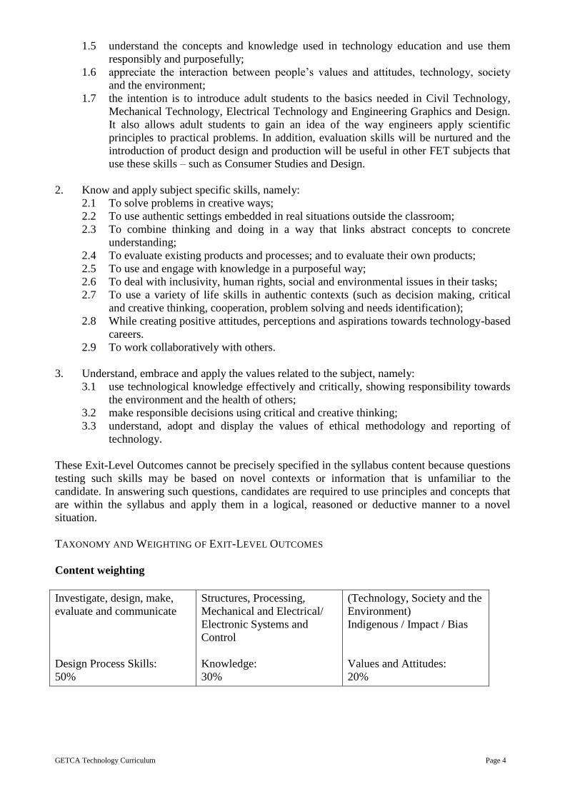
Content weighting
Investigate, design, make,
evaluate and communicate
Design Process Skills:
50%
Structures, Processing,
Mechanical and Electrical/
Electronic Systems and
Control
Knowledge:
30%
(Technology, Society and the
Environment)
Indigenous / Impact / Bias
Values and Attitudes:
20%
GETCA Technology Curriculum Page 5
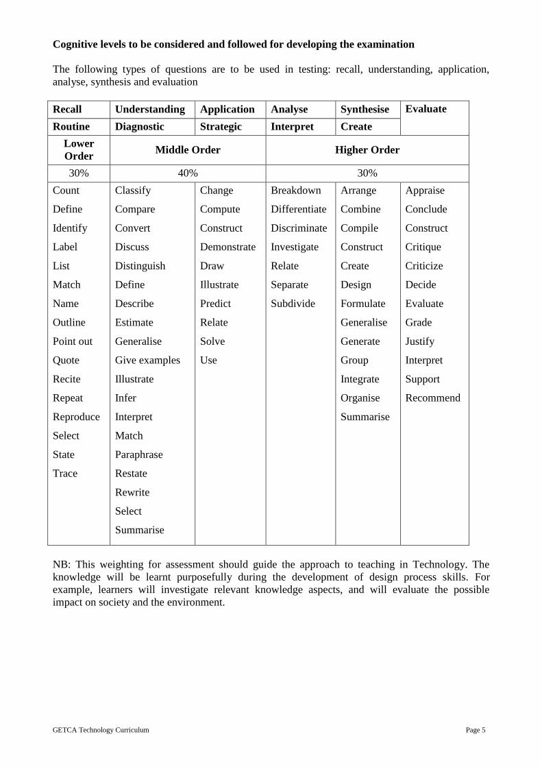
Cognitive levels to be considered and followed for developing the examination
The following types of questions are to be used in testing: recall, understanding, application,
analyse, synthesis and evaluation
Recall Understanding Application Analyse Synthesise Evaluate
Routine Diagnostic Strategic Interpret Create
Lower
Order Middle Order Higher Order
30% 40% 30%
Count
Define
Identify
Label
List
Match
Name
Outline
Point out
Quote
Recite
Repeat
Reproduce
Select
State
Trace
Classify
Compare
Convert
Discuss
Distinguish
Define
Describe
Estimate
Generalise
Give examples
Illustrate
Infer
Interpret
Match
Paraphrase
Restate
Rewrite
Select
Summarise
Change
Compute
Construct
Demonstrate
Draw
Illustrate
Predict
Relate
Solve
Use
Breakdown
Differentiate
Discriminate
Investigate
Relate
Separate
Subdivide
Arrange
Combine
Compile
Construct
Create
Design
Formulate
Generalise
Generate
Group
Integrate
Organise
Summarise
Appraise
Conclude
Construct
Critique
Criticize
Decide
Evaluate
Grade
Justify
Interpret
Support
Recommend
NB: This weighting for assessment should guide the approach to teaching in Technology. The
knowledge will be learnt purposefully during the development of design process skills. For
example, learners will investigate relevant knowledge aspects, and will evaluate the possible
impact on society and the environment.
GETCA Technology Curriculum Page 6
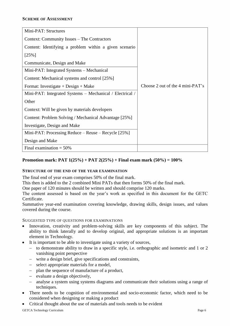
SCHEME OF ASSESSMENT
Mini-PAT: Structures
Context: Community Issues – The Contractors
Content: Identifying a problem within a given scenario
[25%]
Communicate, Design and Make
Choose 2 out of the 4 mini-PAT’s
Mini-PAT: Integrated Systems – Mechanical
Content: Mechanical systems and control [25%]
Format: Investigate + Design + Make
Mini-PAT: Integrated Systems – Mechanical / Electrical /
Other
Context: Will be given by materials developers
Content: Problem Solving / Mechanical Advantage [25%]
Investigate, Design and Make
Mini-PAT: Processing Reduce – Reuse – Recycle [25%]
Design and Make
Final examination = 50%
Promotion mark: PAT 1(25%) + PAT 2(25%) + Final exam mark (50%) = 100%
STRUCTURE OF THE END OF THE YEAR EXAMINATION
The final end of year exam comprises 50% of the final mark.
This then is added to the 2 combined Mini PATs that then forms 50% of the final mark.
One paper of 120 minutes should be written and should comprise 120 marks.
The content assessed is based on the year’s work as specified in this document for the GETC
Certificate.
Summative year-end examination covering knowledge, drawing skills, design issues, and values
covered during the course.
SUGGESTED TYPE OF QUESTIONS FOR EXAMINATIONS
Innovation, creativity and problem-solving skills are key components of this subject. The
ability to think laterally and to develop original, and appropriate solutions is an important
element in Technology.
It is important to be able to investigate using a variety of sources,
to demonstrate ability to draw in a specific style, i.e. orthographic and isometric and 1 or 2
vanishing point perspective
write a design brief, give specifications and constraints,
select appropriate materials for a model,
plan the sequence of manufacture of a product,
evaluate a design objectively,
analyse a system using systems diagrams and communicate their solutions using a range of
techniques.
There needs to be cognition of environmental and socio-economic factor, which need to be
considered when designing or making a product
Critical thought about the use of materials and tools needs to be evident
GETCA Technology Curriculum Page 7
Ethicality needs to be evident
Questions that integrate knowledge, skills and value have more value in technology than a mere
recall of knowledge facts.
Questions should be balanced across Bloom’s Taxonomy BUT with special emphasis on
application of knowledge in a problem-solving context, as this is the essence of this learning
area.
Case Studies Case studies are to be included in examinations.
The intention should be to show that Technology is a subject that is close to the way the world
works.
Case studies can be used both to develop and to assess a technological skill (drawing for
example), knowledge, concepts, and values.
Mini-Practical Assessment Task (Mini-PAT) These are a set of short practical assessment tasks that make up the main formal assessment of the
adult student’s skills and make up 50% of the year mark.
It may be an assignment covering aspects of the design process, or it may be a full capability task
covering all aspects of the design process (IDMEC).
It is composed of a variety of forms of assessment suited to the range of activities that make up a
mini-PAT.
A mini-PAT is intended to formalise the practical component of Technology contextualised within
a knowledge focus.
The mini-Practical Assessment Task is designed to give adult students the opportunity to
develop and demonstrate their levels of ability as they progress through the task’s activities.
Each mini-PAT focuses, primarily on one of the knowledge foci of Technology (viz. structures,
mechanical systems and control, electrical/electronic systems and control and processing), but
may be integrated and may target more than one knowledge focus.
Textbook writers are expected to develop the mini-PATs.
These tasks are structured according to the design process:
Investigate – Design – Make – Evaluate – Communicate.
NB: This is not a linear process happening in a fixed sequence.
Assessment in a mini-PAT need not cover all aspects of the design process each cycle.
A mini-PAT is an extended formal assessment task.
Mini-PAT 1 Content: Structures
Format: Communicate + Design + Make
Mini-PAT 2 Content: Mechanical systems and control
Format: Investigate + Design + Make
Mini-PAT 3 Content: Electronic systems and control
Format: Investigate + Design + Make + Evaluate +
Communicate

GETCA Technology Curriculum Page 8
Mini-PAT 4 Content: Processing
Format: Design + Make
GUIDELINES FOR LECTURERS AND MATERIALS DEVELOPERS
A person studying the subject of technology will be someone with a keen interest in the fields of
mechanisms, electrical/electronic systems, structures and processing. This type of person will be
interested in communicating effectively in the written, annotated and graphic form and will be a
lateral thinker who can work through a process to problem-solve. The kind of student who will take
this subject will be someone who has an interest in computers and realises the need to keep abreast
of technological advancements. This subject has a large practical component and allows for various
learning styles and caters to learners with a variety of non-written abilities.
The curriculum for this subject needs to be well structured, methodical and must follow the
technological process. Space for lateral thinking and creative problem solving are important. It is
imperative that the basics of structures, electrical systems, mechanical systems and processing are
taught first so that the students have a basis from which to work. Critical thinking and prediction is
an important facet of this subject and needs to be developed throughout the technological process.
By following the curriculum, from the basics then through each of the four fields in the given
cycles this will build depth and develop knowledge and skills needed for success. It is important to
make sure that the practical components can be carried out with the minimum materials. However,
for electrical systems this will require a number of electronic components. Waste materials will
suffice to carry out the other three PAT tasks.
To begin with anyone studying technology needs to learn the basics as this forms the backbone to
the four components. This theory forms the basis to carrying out the PATs and for answering
comprehension type questions and exams. A student studying technology needs to be committed
and must work methodically through the steps of the process for each of the components. Creativity
and problem solving skills must be developed and a student of this subject must think laterally.
ASSUMPTIONS ABOUT PRIOR KNOWLEDGE AND SKILLS
Prior knowledge needed for this subject is good communication skills and basic drawing skills. An
ability to think creatively and be able to problem solve are important.

GETCA Technology Curriculum Page 9
THEME 1: STRUCTURES
INTRODUCTION
This theme investigates structures, particularly bridges. The students are required to design and
make a model bridge. In this theme the principles of structures are investigated and applied to the
practical task.
RATIONALE FOR CONTENT SELECTION
Bridges are a good way of using most aspects of structures.
Content
Topic Heading Topic (with Approximate Instructional Time)
1. Investigate and
record the
characteristics of
structure with the
focus on bridges
1.1 Structural study (1 hours)
1.2 Investigate a variety of bridges (1hours)
1.3 Record gives structures strength and stability [look at materials
and structural features (1 hours)
1.4 Record, using drawings and notes, three suitable bridge types to
help solve the problem (1 hour)
2. Drawing 2.1 Orthographic drawings (1 hours)
2.2 Isometric drawings (1 hours)
2.3 Finalise and refine drawings (1 hour)
3. Making 3.1 Materials and Tools needed to make the model, plan way forward
and organise work space (1 hours)
3.2 Use of production schedule – make amendments and continue
making (2 hours)
3.3 Evaluation and refinements based on the brief, specifications and
constraints (1 hours)
4. Written Report:
Evaluate and refine
4.1 Evaluate the model workmanship and adherence to the project
criteria (1 hours)
4.2 Evaluate the process and time management (1 hours)
4.3 Make improvements or refine the model bridge (1 hour)
5. Mini PAT 5.1 Mini PAT (6 hours) refer to the section on Guidelines for Practical
Assessment Tasks
Overview
1.1 Structures Investigation and Planning
Content:
The tender process (including ethical practices).
Investigate the given scenario by looking and various possible structures, which could
solve the problem.
Study existing products relevant to the identified problem in terms of fitness-for-
purpose (including suitability of materials), safety for users, costs of materials and costs
of construction. Realistic costs of real materials, labour, transport, etc.
Look at various types of bridges and give reasons for the three possible types of bridges
that may solve the problem.
Investigate and understand structures and what makes for a solid and stable structure
and that will make this solution successful.

GETCA Technology Curriculum Page 10
Learning Outcomes: Students should be able to:
1.1.1 Investigate and write a tender. [Refer to the checklist]
1.1.2 Investigate and record at least three types of bridges that could possibly solve the
problem of building a model bridge over the river.
1.1.3 Investigate and record by including pictures [with references] or drawings of
various suitable bridges and materials that could solve the problem. Write an
analysis of existing bridges explaining fitness-for-purpose and why they could be
possible solutions to the given problem.
1.1.4 Write a rationale explaining the choices made as possible solutions. [this may be a
paragraph for each bridge or written up in point form]
1.1.5 Write up the characteristics of structures, which will make your model suitable as a
solution e.g. using triangles, as they are stable, taking into account different forces.
1.2 Drawing
Content:
Sketch initial ideas, about two to three different drawings.
An accurate annotated orthographic drawing of the proposed bridge. First angle
orthographic projection: three-dimensional objects on flat paper.
An accurate and annotated isometric drawing of the proposed bridge.
Evaluate and adapt the design [This can be done individually or if the students are
working in teams, they should evaluate individual ideas and develop a final idea]
Learning Outcomes: 1.2.1 Draw at least three different ideas to show solutions to solve the problem [these
should be on the same page and do not have to be accurate, but must have
annotations such as materials, forces applied, structural aspects which strengthen
the proposed model.] There should be three different views: front, top and side. To
help use simple square grid paper underneath the drawing sheet. Use a variety of
line types such as dark, feint, dashes, wavy, and chain. Clearly mark scale and
dimensions.
1.2.2 Make an informed choice of the most suitable bridge to cross the river. Write a
rationale with clear reasons for the choice. [About three reasons]
1.2.3 Produce digitally or draw an accurate and clearly annotated orthographic drawing
of the proposed structure for the model bridge. This should be drawn to scale with
accurate measurements shown. More complex 3D objects drawn in orthographic
projection with instruments.
1.2.4 Produce digitally or draw and accurate and clearly annotated isometric drawing of
the proposed model bridge
1.3 Written Report:
Content:
A written record of the brief, specifications, constraints
Material and tool list
A written plan which follows the technological process to solve the given problem
[IDME] using a flowchart to show the process.
Costing/ budget of the “real-life” solution, including correct materials and labour costs.
Learning Outcomes: Students should be able to:
1.3.1 Write a clear brief [Design and make a… to solve…]
1.3.2 Write, in point form, the specifications.

GETCA Technology Curriculum Page 11
[These are the specific things that the model should solve; write about 5 points
stating what the model/product should do, what it should look like, the weight it
should carry, materials you will use for the model];
1.3.3 Communicate and write a list of the constraints.
[These are the limitations and restrictions that you have such as materials, time,
size, shape, use]
1.3.4 Produce a material and tool list in table form;
1.3.5 Use a flow chart to show the process, which will be followed to make the model.
1.3.6 Produce and record a fairly realistic budget for the project including labour,
materials, hire of equipment,
1.4 Making:
Content:
Set out materials and tools needed to make the model.
Make a model of a viable solution: It must be built neatly to scale, showing intelligent
use of materials.
Students must use safe working practices.
Evaluate: use the brief specifications and constraints to evaluate the model bridge.
Learning Outcomes: Students should be able to:
1.4.1 Prepare materials needed for the model and use the flow chart to follow the work-
plan.
1.4.2 Make the model; ensure that the model is neat and built to scale. Follow the brief,
specifications and constraints and use the final drawing to work from.
1.4.3 Exhibit safe working practice.
1.4.4 Evaluate the model against the brief, specifications and constraints and the final
drawing.
GETCA Technology Curriculum Page 12
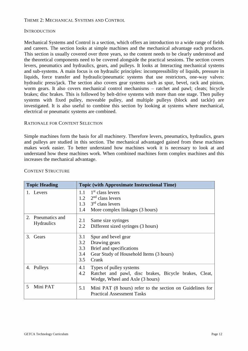
THEME 2: MECHANICAL SYSTEMS AND CONTROL
INTRODUCTION
Mechanical Systems and Control is a section, which offers an introduction to a wide range of fields
and careers. The section looks at simple machines and the mechanical advantage each produces.
This section is usually covered over three years, so the content needs to be clearly understood and
the theoretical components need to be covered alongside the practical sessions. The section covers
levers, pneumatics and hydraulics, gears, and pulleys. It looks at Interacting mechanical systems
and sub-systems. A main focus is on hydraulic principles: incompressibility of liquids, pressure in
liquids, force transfer and hydraulic/pneumatic systems that use restrictors, one-way valves:
hydraulic press/jack. The section also covers gear systems such as spur, bevel, rack and pinion,
worm gears. It also covers mechanical control mechanisms – ratchet and pawl; cleats; bicycle
brakes; disc brakes. This is followed by belt-drive systems with more than one stage. Then pulley
systems with fixed pulley, moveable pulley, and multiple pulleys (block and tackle) are
investigated. It is also useful to combine this section by looking at systems where mechanical,
electrical or pneumatic systems are combined.
RATIONALE FOR CONTENT SELECTION
Simple machines form the basis for all machinery. Therefore levers, pneumatics, hydraulics, gears
and pulleys are studied in this section. The mechanical advantaged gained from these machines
makes work easier. To better understand how machines work it is necessary to look at and
understand how these machines work. When combined machines form complex machines and this
increases the mechanical advantage.
CONTENT STRUCTURE
Topic Heading Topic (with Approximate Instructional Time)
1. Levers 1.1 1st class levers
1.2 2nd class levers
1.3 3rd class levers
1.4 More complex linkages (3 hours)
2. Pneumatics and
Hydraulics 2.1 Same size syringes
2.2 Different sized syringes (3 hours)
3. Gears 3.1 Spur and bevel gear
3.2 Drawing gears
3.3 Brief and specifications
3.4 Gear Study of Household Items (3 hours)
3.5 Crank
4. Pulleys 4.1 Types of pulley systems
4.2 Ratchet and pawl, disc brakes, Bicycle brakes, Cleat,
Wedge, Wheel and Axle (3 hours)
5 Mini PAT 5.1 Mini PAT (8 hours) refer to the section on Guidelines for
Practical Assessment Tasks
GETCA Technology Curriculum Page 13
Overview
2.1 Levers
Content:
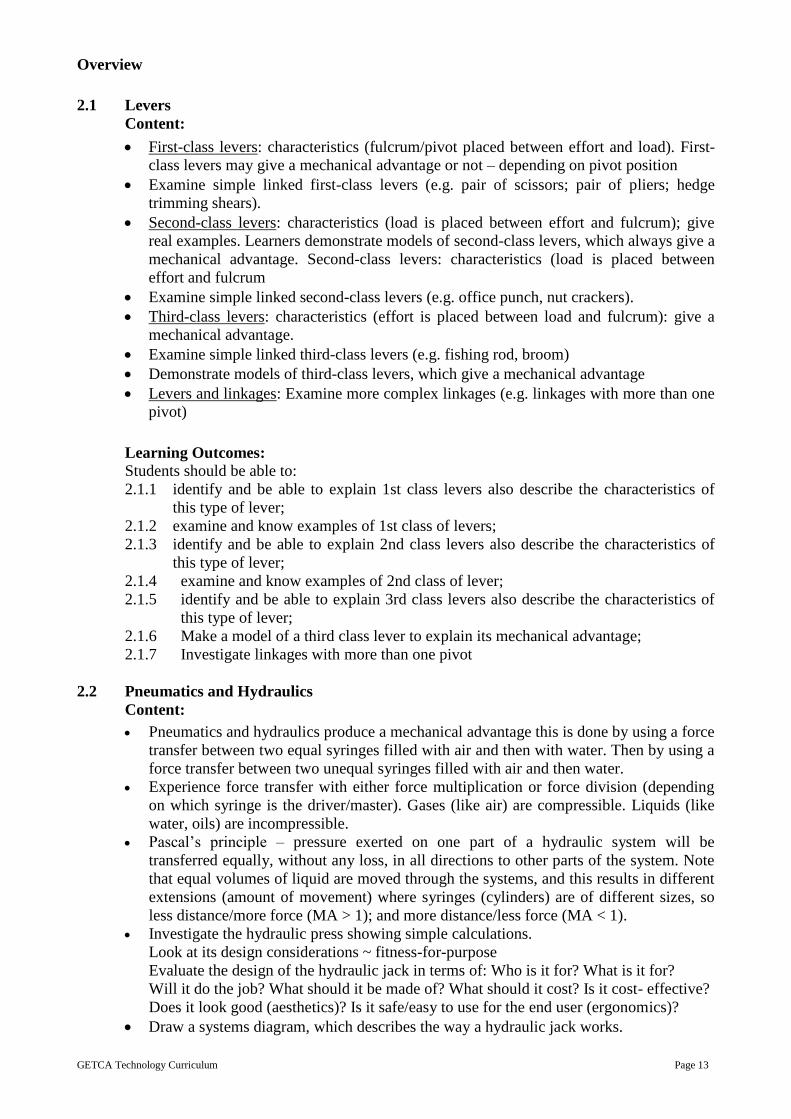
First-class levers: characteristics (fulcrum/pivot placed between effort and load). First-
class levers may give a mechanical advantage or not – depending on pivot position
Examine simple linked first-class levers (e.g. pair of scissors; pair of pliers; hedge
trimming shears).
Second-class levers: characteristics (load is placed between effort and fulcrum); give
real examples. Learners demonstrate models of second-class levers, which always give a
mechanical advantage. Second-class levers: characteristics (load is placed between
effort and fulcrum
Examine simple linked second-class levers (e.g. office punch, nut crackers).
Third-class levers: characteristics (effort is placed between load and fulcrum): give a
mechanical advantage.
Examine simple linked third-class levers (e.g. fishing rod, broom)
Demonstrate models of third-class levers, which give a mechanical advantage
Levers and linkages: Examine more complex linkages (e.g. linkages with more than one
pivot)
Learning Outcomes: Students should be able to:
2.1.1 identify and be able to explain 1st class levers also describe the characteristics of
this type of lever;
2.1.2 examine and know examples of 1st class of levers;
2.1.3 identify and be able to explain 2nd class levers also describe the characteristics of
this type of lever;
2.1.4 examine and know examples of 2nd class of lever;
2.1.5 identify and be able to explain 3rd class levers also describe the characteristics of
this type of lever;
2.1.6 Make a model of a third class lever to explain its mechanical advantage;
2.1.7 Investigate linkages with more than one pivot
2.2 Pneumatics and Hydraulics
Content:
Pneumatics and hydraulics produce a mechanical advantage this is done by using a force
transfer between two equal syringes filled with air and then with water. Then by using a
force transfer between two unequal syringes filled with air and then water.
Experience force transfer with either force multiplication or force division (depending
on which syringe is the driver/master). Gases (like air) are compressible. Liquids (like
water, oils) are incompressible.
Pascal’s principle – pressure exerted on one part of a hydraulic system will be
transferred equally, without any loss, in all directions to other parts of the system. Note
that equal volumes of liquid are moved through the systems, and this results in different
extensions (amount of movement) where syringes (cylinders) are of different sizes, so
less distance/more force (MA > 1); and more distance/less force (MA < 1).
Investigate the hydraulic press showing simple calculations.
Look at its design considerations ~ fitness-for-purpose
Evaluate the design of the hydraulic jack in terms of: Who is it for? What is it for?
Will it do the job? What should it be made of? What should it cost? Is it cost- effective?
Does it look good (aesthetics)? Is it safe/easy to use for the end user (ergonomics)?
Draw a systems diagram, which describes the way a hydraulic jack works.
GETCA Technology Curriculum Page 14
Learning Outcomes: Students should be able to:
2.2.1 Investigate and explain how pneumatics and hydraulics are used to obtain a
mechanical advantage. By using a force transfer between two equal syringes filled
with air and then water.
2.2.2 Investigate and explain by using a force transfer between two unequal syringes filled
with air and then water.
2.2.3 Investigate and explain how force transfer with either force multiplication or force
division, this will depend on which syringe is the driver. Show that gases like air are
compressible and liquids like water, oils are incompressible.
2.2.4 Explain, using Pascal’s principles, how pressure exerted on one part of a hydraulic
system will be transferred equally, without any loss, in all directions to other parts of
the system.
2.2.5 Investigate the hydraulic press/jack and evaluate the design of the in terms of: Who
is it for? What is it for? Will it do the job? What should it be made of? What should
it cost? Is it cost-effective? Does it look good (aesthetics)? Is it safe/easy to use for
the end user (ergonomics)?
2.2.6 Draw a hydraulic press/jack and explain how it works.
2.3 Gears
2.3.1 Spur and bevel gears
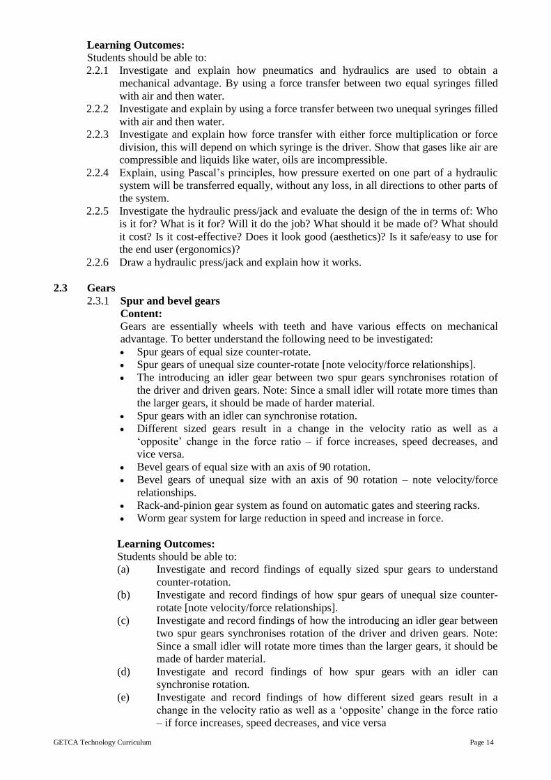
Content: Gears are essentially wheels with teeth and have various effects on mechanical
advantage. To better understand the following need to be investigated:
Spur gears of equal size counter-rotate.
Spur gears of unequal size counter-rotate [note velocity/force relationships].
The introducing an idler gear between two spur gears synchronises rotation of
the driver and driven gears. Note: Since a small idler will rotate more times than
the larger gears, it should be made of harder material.
Spur gears with an idler can synchronise rotation.
Different sized gears result in a change in the velocity ratio as well as a
‘opposite’ change in the force ratio – if force increases, speed decreases, and
vice versa.
Bevel gears of equal size with an axis of 90 rotation.
Bevel gears of unequal size with an axis of 90 rotation – note velocity/force
relationships.
Rack-and-pinion gear system as found on automatic gates and steering racks.
Worm gear system for large reduction in speed and increase in force.
Learning Outcomes: Students should be able to:
(a) Investigate and record findings of equally sized spur gears to understand
counter-rotation.
(b) Investigate and record findings of how spur gears of unequal size counter-
rotate [note velocity/force relationships].
(c) Investigate and record findings of how the introducing an idler gear between
two spur gears synchronises rotation of the driver and driven gears. Note:
Since a small idler will rotate more times than the larger gears, it should be
made of harder material.
(d) Investigate and record findings of how spur gears with an idler can
synchronise rotation.
(e) Investigate and record findings of how different sized gears result in a
change in the velocity ratio as well as a ‘opposite’ change in the force ratio
– if force increases, speed decreases, and vice versa

GETCA Technology Curriculum Page 15
(f) Investigate and record findings of bevel gears, of equal size, with an axis of
90 rotation.
(g) Investigate and record findings of bevel gears of unequal size with an axis
of 90 rotation – note velocity/force relationships.
(h) Investigate and record findings of a rack-and-pinion gear system as found
on automatic gates and steering racks.
(i) Investigate and record findings of worm gear system for large reduction in
speed and increase in force.
2.3.2 Drawing gears
Content
Gears are mechanisms that change the direction of movement. These should be
represented graphically to show:
the driven gear rotating in the opposite direction to the driver (counter rotation).
the driven gear rotating in the same direction to the driver (include an idler gear).
the driven gear rotating faster than the driver (with and without an idler).
Gearing up.
the driven gear rotating slower than the driver (with and without an idler).
Gearing down.
(a) Draw accurately and label the driven gear rotating in the opposite direction
to the driver (counter rotation).
(b) Draw accurately and label the driven gear rotating in the same direction to
the driver (include an idler gear).
(c) Draw and label the driven gear rotating faster than the driver (with and
without an idler). Gearing up
(d) Draw and label • the driven gear rotating slower than the driver (with and
without an idler). Gearing down
2.3.3 Gears brief and specifications
Content
Write a design brief with specifications for a device that will use a combination
of gears to achieve:
A mechanical advantage with force multiplication of three times.
An increase in output velocity of four times.
Learning Outcomes: Students should be able to:
(a) Write a design brief for a device that will use a combination of gears to
achieve:
A mechanical advantage with force multiplication of three times.
An increase in output velocity of four times.
(b) Write clear specifications for a device that will use a combination of gears to
achieve:
A mechanical advantage with force multiplication of three times.
An increase in output velocity of four times.
GETCA Technology Curriculum Page 16
2.3.4 Gears Study of Household Items
Content
Examine various items using mechanisms found in the modern kitchen and/or
home, workshop/garage. Items like can openers, egg beaters, ‘strap’ spanners for
opening bottles, knives for a range of purposes, and vice grip, wire strippers,
scissors, and ratchet spanners should be evaluated in terms of: Who is it for?
What is it for? Will it do the job? What material is it made of? Is the material
suitable? What should it cost? Does it look good [aesthetics]? Is it safe and easy
to use? Report on three items.
Learning Outcomes: Students should be able to:
(a) Examine and record findings of various items, using mechanisms, found in
the modern kitchen and/or home, workshop/garage. These could be can
openers, egg beaters, ‘strap’ spanners for opening bottles, knives for a range
of purposes, and vice grip, wire strippers and ratchet spanners should be
evaluated in terms of: Who is it for? What is it for? Will it do the job? What
material is it made of? Is the material suitable? What should it cost? Does it
look good [aesthetics]? Is it safe and easy to use [ergonomics]? Write a
report on three items.
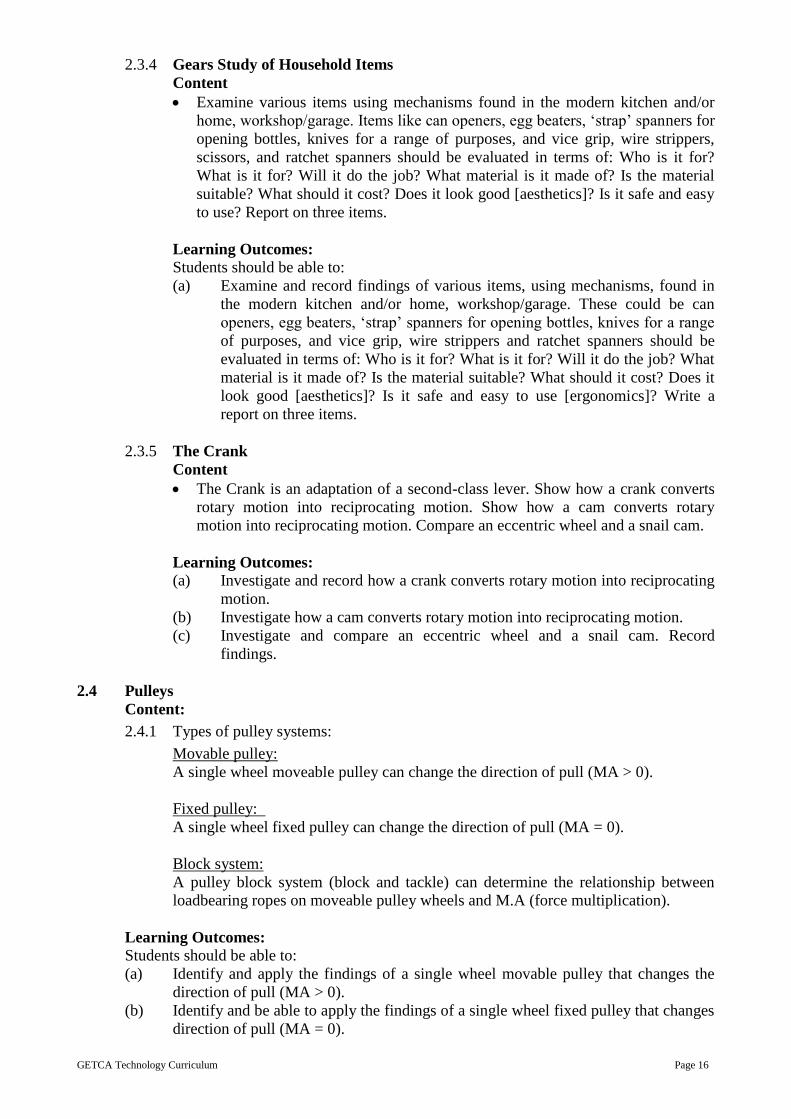
2.3.5 The Crank
Content
The Crank is an adaptation of a second-class lever. Show how a crank converts
rotary motion into reciprocating motion. Show how a cam converts rotary
motion into reciprocating motion. Compare an eccentric wheel and a snail cam.
Learning Outcomes: (a) Investigate and record how a crank converts rotary motion into reciprocating
motion.
(b) Investigate how a cam converts rotary motion into reciprocating motion.
(c) Investigate and compare an eccentric wheel and a snail cam. Record
findings.
2.4 Pulleys
Content:
2.4.1 Types of pulley systems:
Movable pulley:
A single wheel moveable pulley can change the direction of pull (MA > 0).
Fixed pulley:
A single wheel fixed pulley can change the direction of pull (MA = 0).
Block system:
A pulley block system (block and tackle) can determine the relationship between
loadbearing ropes on moveable pulley wheels and M.A (force multiplication).
Learning Outcomes: Students should be able to:
(a) Identify and apply the findings of a single wheel movable pulley that changes the
direction of pull (MA > 0).
(b) Identify and be able to apply the findings of a single wheel fixed pulley that changes
direction of pull (MA = 0).

GETCA Technology Curriculum Page 17
(c) Identify and apply the findings of a pulley block system (block and tackle) to
determine the relationship between loadbearing ropes on moveable pulley
wheels and M.A (force multiplication).
2.4.2 Ratchet and pawl, disc brakes, Bicycle brakes, Cleat, Wedge, Wheel and Axle
Content:
Mechanical control systems:
Ratchet and pawl.
Disc brake.
Bicycle brake.
Cleat
All complex machinery consists of combinations of simple mechanisms.
The wedge: e.g. inclined plane or ramp, door wedge, knife blade, etc.
The wheel and axle: e.g. from bicycle to shopping trolley.
Learning Outcomes: Students should be able to:
(a) Investigate and record mechanical control systems of the following: ratchet
and pawl, disc brake, bicycle brake, and cleat];
(b) Investigate complex machinery and record findings of the wedge and the
wheel and axle.

GETCA Technology Curriculum Page 18
THEME 3: ELECTRICAL SYSTEMS AND CONTROL
INTRODUCTION
Electrical Systems and Control form a vital part of modern-day life, from the basic light bulb to
sophisticate electronic devise. The study of this topic opens the doors to a number of career
choices. It helps to provides an in-depth study of how we get electricity in our homes, how to create
circuits. This is quite a complex section and should be guided carefully with clear hands-on tuition.
RATIONALE FOR CONTENT SELECTION
This is a section, which is an important aspect of modern-day life and offers a gateway to careers
using electrical and electronic devices.
CONTENT STRUCTURE
Topic Heading Topic (with Approximate Instructional Time)
1. Magnetism 1.1 Investigate magnetism(half an hours)
1.2 Make an Electro magnet (half an hours)
2 Simple, series and
parallel circuits
2.1 Simple circuit and circuit diagram drawing (half an hours)
2.2 Series Circuit and circuit diagram drawing (half an hours)
2.3 Parallel circuit and circuit diagram drawing (half an hours)
3 Energy for heating,
lighting and
cooking in rural
areas
3.1 Investigate (half an hours)
3.2 Report (1 hours)
4 Electro chemical
cells
4.1 How to make an electro chemical with vegetables or fruits (half
an hours)
5 Alternative Forms
of Energy
5.1 Investigate various alternative forms of energy (1 hours)
5.2 Tabulate the pros and cons of thermal energy (half an hours)
5.3 Tabulate the pros and cons of hydroelectric energy (half an
hours)
6 Ohm’s Law 6.1 Investigate alternating current Ohm’s Law (2 hours)
7 Basic electronics 7.1 Investigate various components (2 hours)
7.2 Draw and assemble a simple circuit (2 hours)
8 Basic electronics 8.1 Investigate various components (2 hours)
8.2 Draw and assemble a simple circuit (2 hours)
9 Mini PAT 9.1 Mini PAT(4,5 hours) refer to the section on Guidelines for
Practical Assessment Tasks
GETCA Technology Curriculum Page 19
Overview
3.1 Magnetism
Content:
Investigate: Magnetism
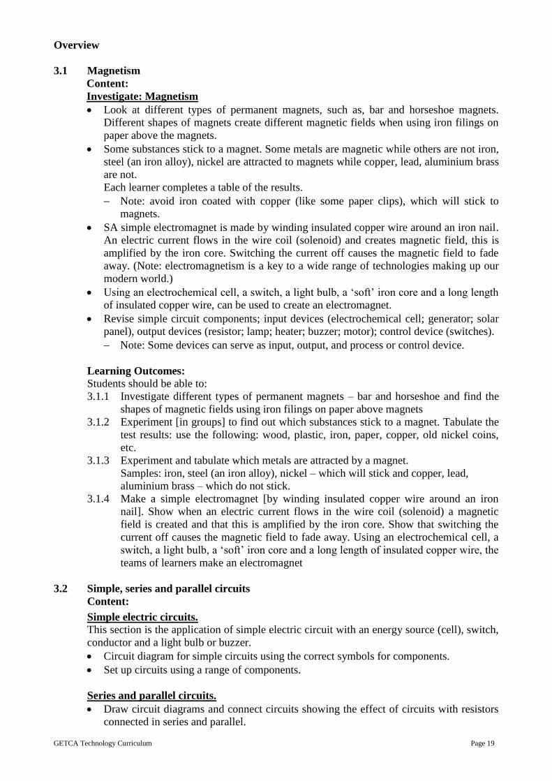
Look at different types of permanent magnets, such as, bar and horseshoe magnets.
Different shapes of magnets create different magnetic fields when using iron filings on
paper above the magnets.
Some substances stick to a magnet. Some metals are magnetic while others are not iron,
steel (an iron alloy), nickel are attracted to magnets while copper, lead, aluminium brass
are not.
Each learner completes a table of the results.
Note: avoid iron coated with copper (like some paper clips), which will stick to
magnets.
SA simple electromagnet is made by winding insulated copper wire around an iron nail.
An electric current flows in the wire coil (solenoid) and creates magnetic field, this is
amplified by the iron core. Switching the current off causes the magnetic field to fade
away. (Note: electromagnetism is a key to a wide range of technologies making up our
modern world.)
Using an electrochemical cell, a switch, a light bulb, a ‘soft’ iron core and a long length
of insulated copper wire, can be used to create an electromagnet.
Revise simple circuit components; input devices (electrochemical cell; generator; solar
panel), output devices (resistor; lamp; heater; buzzer; motor); control device (switches).
Note: Some devices can serve as input, output, and process or control device.
Learning Outcomes: Students should be able to:
3.1.1 Investigate different types of permanent magnets – bar and horseshoe and find the
shapes of magnetic fields using iron filings on paper above magnets
3.1.2 Experiment [in groups] to find out which substances stick to a magnet. Tabulate the
test results: use the following: wood, plastic, iron, paper, copper, old nickel coins,
etc.
3.1.3 Experiment and tabulate which metals are attracted by a magnet.
Samples: iron, steel (an iron alloy), nickel – which will stick and copper, lead,
aluminium brass – which do not stick.
3.1.4 Make a simple electromagnet [by winding insulated copper wire around an iron
nail]. Show when an electric current flows in the wire coil (solenoid) a magnetic
field is created and that this is amplified by the iron core. Show that switching the
current off causes the magnetic field to fade away. Using an electrochemical cell, a
switch, a light bulb, a ‘soft’ iron core and a long length of insulated copper wire, the
teams of learners make an electromagnet
3.2 Simple, series and parallel circuits
Content:
Simple electric circuits. This section is the application of simple electric circuit with an energy source (cell), switch,
conductor and a light bulb or buzzer.
Circuit diagram for simple circuits using the correct symbols for components.
Set up circuits using a range of components.
Series and parallel circuits.
Draw circuit diagrams and connect circuits showing the effect of circuits with resistors
connected in series and parallel.

GETCA Technology Curriculum Page 20
Set up circuits for the following: Lamps in series and parallel.
Switches in series (AND logic) and parallel (OR logic).
Current in the circuit – conventional current flows from positive to negative.
One cell, switch, two lamps in series.
Two cells in series, switch, two lamps in series
Learning Outcomes: Students should be able to:
3.2.1 Draw a simple circuit using the correct symbols for the components.
3.2.2 Make a simple circuit with a range of different components such as a cell, switch,
light bulb, conductor, or buzzer.
3.2.3 Draw a series circuit using the correct symbols for the components.
3.2.4 Draw a parallel circuit using the correct symbols for the components.
3.2.5 Set up circuits showing Set up circuits for the following: Lamps in series and
parallel. Switches in series (AND logic) and parallel (OR logic). Current in the
circuit – conventional current flows from positive to negative. One cell, switch, two
lamps in series. Two cells in series, switch, two lamps in series
3.3 Energy for heating, lighting and cooking in rural and informal settlements
Content:
Energy for heating, lighting and cooking in rural and informal settlements.
Look at energy from illegal connections, focusing on ethical issues and safety
considerations.
Equitable sharing of resources, such as the needs of industry; reliable power for job
creation; schools and homes needs such as power for lighting and computing.
Learning Outcomes: Students should be able to:
3.3.1 Investigate and report on illegal connections focusing on the ethical issues and
safety considerations.
3.3.2 Investigate and report on equitable sharing of resources in terms of the needs of
industry, how jobs can be created through reliable power sources and the needs of
power for schools and homes.
3.4 Electrochemical cells and Solar Power
Content:
Electrochemical cells.
Study how to make batteries using fruit, vegetable and salt water.
Look at the advantages and disadvantages of series and parallel batteries.
Look at photovoltaic cells and investigate the advantages and disadvantages of solar
cells.
Learning Outcomes: Students should be able to:
3.4.1 Make and test a battery using fruit vegetables and salt water;
3.4.2 Tabulate the advantages and disadvantages of series and parallel batteries];
3.4.3 Tabulate the advantages and disadvantages of solar cells photovoltaic cells.
3.5 Investigation of various sources of power
Generate electricity for the nation Thermal power stations, steam turbines – sources of heat: coal, gas, nuclear, sun).
Hydroelectric power stations including pumped storage schemes and then wind-driven
turbines.

GETCA Technology Curriculum Page 21
Learning Outcomes: Students should be able to:
3.5.1 Tabulate the advantages and disadvantages of thermal power stations and steam
turbines as a source of heat using coal, gas, nuclear power and solar power.
3.5.2 Tabulate the advantages and disadvantages of hydroelectric power stations
including pumped storage schemes and wind-driven turbines
3.6 Altering Current –Ohm’s Law
Content:
Alternating current: step-up and step down transformers; distributing electric power
across the country: the national grid.
Introduce Ohm’s Law qualitatively, without calculations. Use one cell, then two cells,
and then three cells connected in series and note the effect on the brightness of a lamp.
The conclusion is that more cells in series (more voltage) will cause the current strength
to increase, if the resistance does not change. Ohm’s law quantitatively: as voltage
increases, current increases if resistance is constant.
Ohm’s Law to measure the voltage (potential difference) and the current strength in each of
the following circuits:
One cell connected to a 20 W resistor – note the voltmeter and ammeter readings.
Two cells connected to the 20 W resistor – note the voltmeter and ammeter readings.
Three cells connected to the 20 W resistor – note the voltmeter and ammeter readings
Plot the readings on a graph and determine the relationship between potential difference
and current strength while keeping the resistance constant.
AND logic gate and look at simple cases where it is used.
OR logic gate, and look at simple cases where it is used.
Truth tables for AND & OR logic conditions.
Learning Outcomes: Students should be able to:
3.6.1 Introduce and investigate Ohm’s Law qualitatively without calculations. Use one
cell, then two cells, and then three cells connected in series and note the effect on
the brightness of a lamp. They must conclude that more cells in series (more
voltage) will cause the current strength to increase, if the resistance does not change.
3.6.2 Test Ohm’s Law to measure the voltage (potential difference) and the current
strength in each of the following circuits:
One cell connected to a 20 W resistor – note the voltmeter and ammeter
readings.
Two cells connected to the 20 W resistor – note the voltmeter and ammeter
readings.
Three cells connected to the 20 W resistor – note the voltmeter and ammeter
readings
Plot the readings on a graph and determine the relationship between potential
difference and current strength while keeping the resistance constant.
AND logic gate and look at simple cases where it is used.
OR logic gate, and look at simple cases where it is used.
Truth tables for AND & OR logic conditions.
GETCA Technology Curriculum Page 22
3.7 Electronic components
Content:
Resistor colour codes:
Low value resistors often have their resistance value printed on them in numbers.
Higher value resistors are coded using coloured bands. The first three bands give the
value of the resistor in ohms. The fourth band is an accuracy rating as a percentage.
Calculate values:
R = VI use to calculate R if V and I are known.
V = IR use to calculate V if I and R are known.
I = VR use to calculate I if V and R are known.
Note: R – represents the resistance of a resistor in ohms … [Ω].
V – represents the potential difference in volts … [V].
I – represents the current strength in amperes … [A].
Switches: Manual switches controlled by the user, e.g. push, SPST, SPDT, DPDT.
Diodes and LED (Light Emitting Diode):
A diode is a component that allows current to flow in one direction only.
A LED allows current to flow in one direction only and also gives off light and is often
used as an indicator that a circuit is ‘ON’.
Transistors: only npn-type will be used at this level.
A transistor is a device that can act as a switch and it can amplify a small current (e.g. from
a sensor) into a larger current.
Connect a simple transistor circuit.
Sensors – important input devices:
LDR (Light Dependent Resistor) – a component whose resistance decreases with light
[dark – high resistance; bright light – low resistance].
Thermistor: a component whose resistance varies with temperature. Two types exist:
+ t: resistance increases with increasing temperature.
- t: resistance decreases with increasing temperature.
Touch or moisture detector: a component that can be bridged using a ‘wet’ finger, thus
completing the circuit, indicating the touch.
Capacitors: a component which can store and then release electrical energy.
Simple electronic circuits: Draw, and assemble the following simple electronic circuits
LED, 470 Ω resistor, switch, and 4,5 V series battery.
LDR, buzzer, 3 V series battery.
NPN transistor, buzzer or bell, thermistor, variable resistor, 1 kΩ resistor, 6 V series battery
(or DC power supply or photovoltaic panel).
6 V series battery, LED, 470 Ω resistor, 1 000 μF capacitor, switch.
Learning Outcomes: Students should be able to:
3.7.1 Investigate, be able to read the symbols and be able to read the resistor codes and
be able to apply the correct resistor in a given circuit.
3.7.2 Investigate, be able to read the symbols and be able to understand how various
switches work. Be able to apply the correct switch in a given circuit.
3.7.3 Investigate, be able to read the symbols and be able to apply transistors correctly to
given circuits.

GETCA Technology Curriculum Page 23
3.7.4 Investigate, be able to read the symbols and be able to apply LDRs and thermistors
correctly in given circuits.
3.7.5 Investigate, be able to read the symbols and be able to apply touch or moisture
sensors correctly in given circuits.
3.7.6 Draw and be able to assemble the following simple electronic circuits: LED, 470 Ω
resistor, switch, and 4,5 V series battery.
LDR, buzzer, 3 V series battery.
NPN transistor, buzzer or bell, thermistor, variable resistor, 1 kΩ resistor, 6 V
series battery (or DC power supply or photovoltaic panel).
6 V series battery, LED, 470 Ω resistor, 1 000 μF capacitor, switch.

GETCA Technology Curriculum Page 24
THEME 4: PROCESSING
INTRODUCTION
In today’s world it is critical to look at processing, particularly in terms of repurposing items such
as plastic to help alleviate the pollution problems we have. It is also worthwhile looking at
indigenous technologies such as traditional ways of preserving foods given the problems created by
preservatives. Indigenous technologies are most useful and must not be forgotten.
RATIONALE FOR CONTENT SELECTION
Three areas of processing are looked at in this section. The first is processing and preserving
metals. The next is processing and preserving food with a focus on indigenous technologies,
looking at traditional ways of preserving foods. The last section deals with plastic. Ineffective
disposal of plastic has led to widespread pollution and through this investigation it is hoped that the
adult student will look at a variety of ways to repurpose plastic, ethically and responsibly.
PROCESSING
Topic Heading Topic (with Approximate Instructional Time)
1. Processing and
Preserving Metals
1.1 Research Painting (half an hours)
1.2 Research Galvanising (half an hours)
1.3 Electroplate an item (practical)(1 hours)
2 Processing –
Indigenous
technologies
2.1 Storing grain (half an hours)
2.2 Pickling (half an hours)
2.3 Drying or salting (practical) (1. hours)
3 Processing plastic 3.1 Recycling (half an hours)
3.2 Moulding (half an hours)
3.3 Remanufacturing waste plastic (1 hours)
4 Mini PAT 4.1 Mini PAT (4 hours) refer to the section on Guidelines for
Practical Assessment Tasks
Overview
4.1 Processing and Preserving metals:
Painting
Galvanising
Electroplating
Learning Outcomes: Students should be able to:
4.1.1 Investigate and report on how painting metals helps to preserve them.
4.1.2 Investigate and report on how galvanising metals helps to preserve them.
4.1.3 Investigate and electroplate a metal to show how it can help to preserve it.
4.2 Indigenous Technology – Preserving foods
Content:
Indigenous technology to preserve foods:
Storing grain
Pickling
Drying and/or salting [this is to be carried out practically]
GETCA Technology Curriculum Page 25
Learning Outcomes: Students should be able to:
4.2.1 Investigate and report on how grain is traditionally preserved in South Africa
4.2.2 Investigate and report on how foods are pickled traditionally in South Africa;
4.2.3 Either salt or dry a food type using traditional methods of salting or drying
techniques
4.3 Processing Plastic
Content:
Types of plastics and their uses.
Investigation: identification of plastic identifying-codes and sorting for recycling.
Properties of plastics
Reduce – reuse – recycle
Case study: Remanufacturing waste plastic into pellets for re-use.
Systems diagram: Draw a systems diagram describing a plastics recycling project.
Case study: Moulding recycled plastic pellets into products.
Learning Outcomes: Students should be able to:
4.3.1 Investigate and report on various types of plastic and their uses;
4.3.2 Identify plastic identifying-codes and sorting for recycling;
4.3.3 Tabulate the properties of plastics;
4.3.4 Make a poster to promote reducing, reusing and recycling of plastics;
4.3.5 Investigate and write a report on the remanufacturing of waste plastic into pellets for
re-use;
4.3.6 Investigate and draw a systems diagram describing a plastic recycling project;
4.3.7 Research and write about how recycled plastic pellets are moulded into products.
SUGGESTED STUDY HOURS
Technology is an 11-credit course, which relates to about 92 notional hours.
It is envisaged that a typical one-year offering of the course will cover 20 weeks, excluding
revision and examination time. Adult students should therefore spend about 6 hours per week on
Technology. This should consist of hours of face-to-face instruction and self-study per week and an
hour test after each section, and 2-hour examination. Because of the intense practical component
this subject requires clearly devised and in-depth hands-on time. In this way the theory is applied
and studying for tests and examinations is not a gruelling as for other subjects.
The section Electrical Systems and Control needs face-to-face teaching as the components need to
be well explained before making the circuits. These are costly and components may be difficult to
find. Learning the basics and making models for Mechanical Systems and Control also requires
face-to-face time and an in-depth understanding of simple machines before embarking on model
making. Structures and Processing also require a solid foundation of the principles before doing the
practical tasks. It is vital for this subject that the practical component be carried out as effectively
as possible as this forms the crux of the subject.
We recommend that the theory of each section be studied first, and then each section follows with
the mini-PAT or practical tasks and then the section test to ensure progressive development within
each of these sections.

GETCA Technology Curriculum Page 26
A suggested time allocation for the course is shown in the table below:
Component Face-to-face Teaching
Time
Self-study Time
Structures 4 hours per week 5 weeks
including Mini PAT
2 hours per week 5 week
Mechanical systems
and control
4 hours per week 5 weeks
including Mini PAT
2 hours per week × 5
Electrical systems
and control
4 hours per week 5 weeks
including Mini PAT
2 hours per week × 5
Processing 4 hours per week 5 weeks
including Mini PAT
2 hours for final examination
1 hours per week × 5
2 hours for Final
Examination
Total Course Hours 92 hours

GETCA Technology Curriculum Page 27
ANNEXURE
Background content and skills which is needed to complete the tasks
6. The technological process
Process Skills: Learners must identify a problem, need or opportunity from a given real-life context.
Investigate: Investigating a situation means to gain information and is an important starting point
for this subject. Research or finding of information mainly takes place here. Adult students need to
gather data and information, grasp concepts and gain insight, find out about new techniques, etc. or
indigenous technologies. Some skills needed for investigating are information accessing and
processing skills, recording, identifying, predicting, comparing, observing, classifying, interpreting,
collating, etc. background context, nature of the need, environmental situation, and people
concerned.
Locates and collects information: Compares, sorts, verifies, evaluates (cross-checking different
sources or resources) and stores information.
Design: Once a problem is clearly understood, the design brief needs to be written. Possible
solutions should then be generated. These ideas may be drawn on paper. The first idea may not
necessarily be the best; so several different solutions are desirable. This part of the design process
requires awareness and the knowledge and skills associated with graphics, such as the use of
colour, rendering techniques, 2D and 3D drawings, etc. These in essence include abilities in
planning, sketching, drawing, calculating, modeling, and managing resources. Once possible
solutions are considered, a decision must be made. The chosen solution will be the one that best
satisfies the specifications. It is expected that learners justify choices made. At this point final
drawings/sketches (working drawings) of the chosen solution should be prepared. They should
contain all the details needed for making the product or system. These include instructions,
dimensions, annotated notes, etc. Testing, simulating or modeling the solutions need to be done
before final manufacture is done here. for people, purpose, appearance, environment, safety, real
costs, ergonomics, quality, and production.
Writes a design brief, this is a short and clear statement that gives the general outline of the
problem to be solved as well as the purpose of the proposed solutions. Next the specifications are
considered and recorded. These are an organised, detailed description of the criteria that the
solution or product must meet, e.g. safety, size, material, function, human rights, environment and
so on. The constraints follow this and are aspects that limit conditions within which the work or
solution must be developed, e.g. time, materials, tools, human resource, cost and so on.
Generates a range of possible solutions using sketches with explanatory notes.
Selects the most viable solution using well-reasoned argument.
Make: develops plans for making detailing: resources, dimensions, making steps (such as flow
diagrams). Draws simple assembly drawings (exploded diagrams) if needed. Draws working
drawings using first angle orthographic projections. Chooses and uses appropriate tools and
materials to make products by measuring/marking, cutting/separating, shaping/forming, joining/
combining and finishing with accuracy. Changes and adapts design ideas where appropriate. Uses
safe working practices and uses correct tools for the job appropriately.

GETCA Technology Curriculum Page 28
Evaluate: evaluates the product or system in terms of the design brief. Evaluates the process
followed and suggests sensible improvements or modifications to the solution in terms of fitness
for purpose.
Communicate: 3D and 2D sketches, plans using first angle orthographic projection, circuit
diagrams with standard electrical and electronic component symbols, systems diagrams and simple
flow charts. Plans include scale, thick, thin, dashed and chain lines, dimensions and quantities.
Artistic drawings in either single or double VP perspective should be enhanced using colour,
texture, shading and shadows.
7. Drawing
Sketches and Working Drawings When designing a 3D object, like a milk jug, the industrial designer is likely to visualise the jug
and draw it using 3D isometric view and a 2D orthographic drawings. Sketches are the most
effective way of communicating design ideas. This is especially true in our multi-lingual society.
The language of graphics transcends spoken language and is generally unambiguous once the
students become familiar with the drawing conventions.
NB: It is important to understand that the suitability of the design (fitness-for-purpose)
Free-hand sketching. [note that free hand requires the use of a geometry set
2D working drawings in first angle orthographic projection: elementary use of instruments.
[<https://powerengineeringwiki.wikispaces.com/file/view/3d_ortho.jpg/488842760/3d_ortho.jpg>]
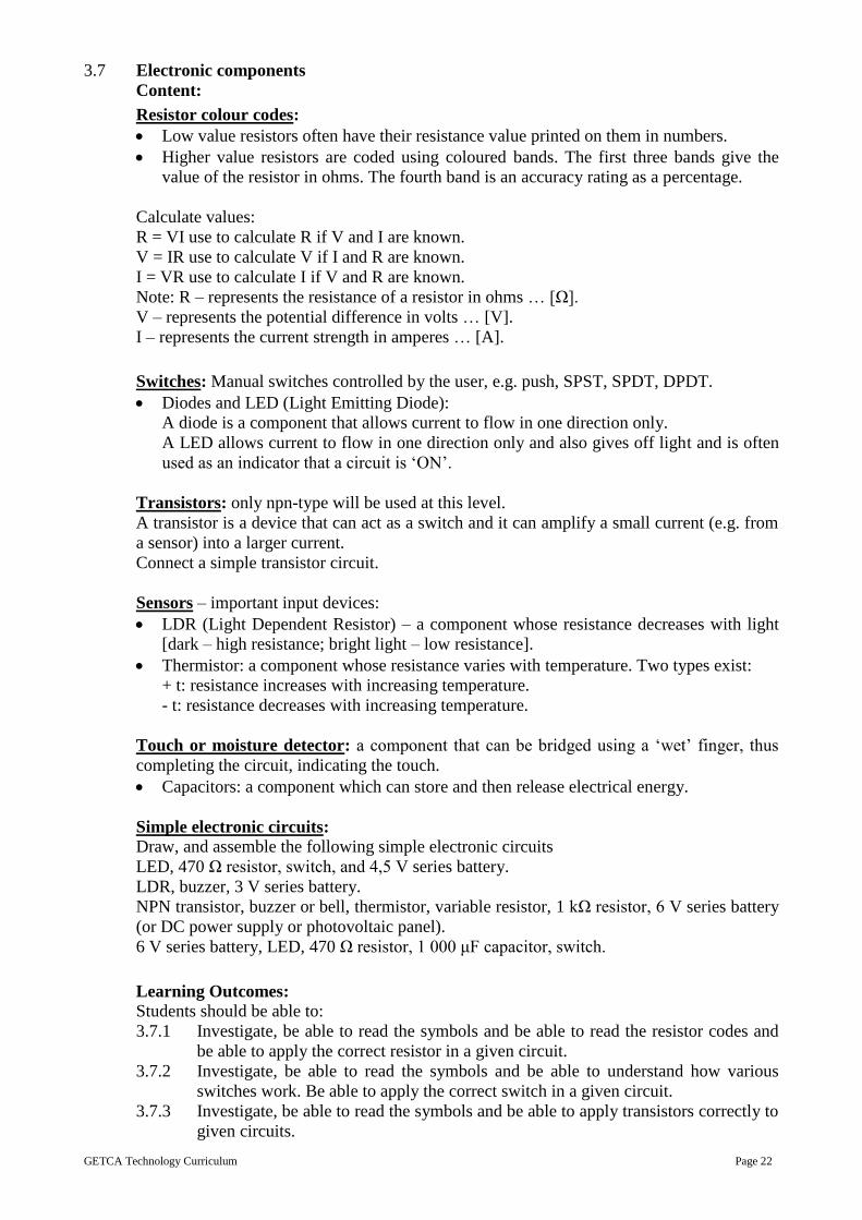
3D isometric projection: 30° drawn using underlying grid to scale, correct line types and
dimensions.
http://www.technologystudent.com/designpro/isomet2a.png
GETCA Technology Curriculum Page 29
[<http://study.com/academy/lesson/what-is-an-isometric-drawing-definition-examples.html>]
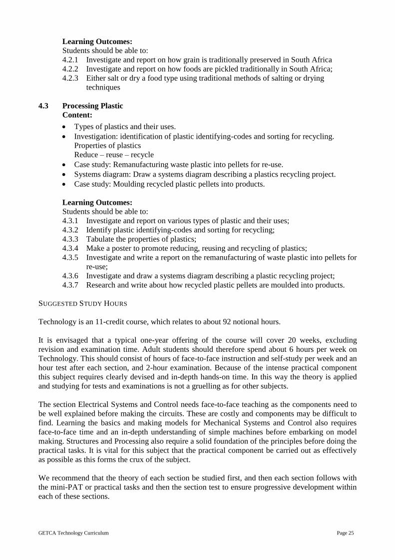
The grid below could be used to practice drawing at a thirty-degree angle.
[<http://archive.cnx.org/contents/30ad6e16-3ad4-42de-8c9c-2ee69aa5e18e@1/designing-and-making-a-container>]
Line types: outlines, construction lines, hidden detail lines, centre lines, wavy lines.
Dimensioning: conventions, arrows.
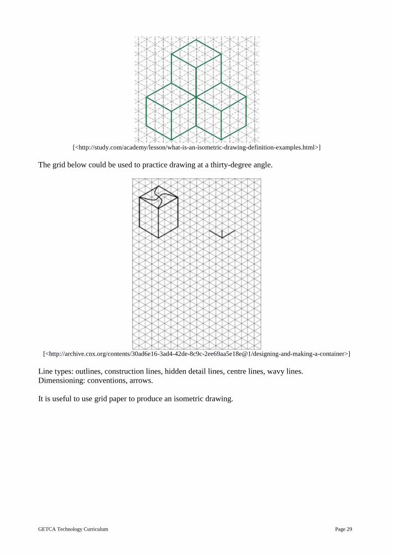
It is useful to use grid paper to produce an isometric drawing.
GETCA Technology Curriculum Page 30
[<https://mediacacak0.pinimg.com/originals/3c/9e/80/3c9e809a9e341942567e493b0f255215.jpg>]
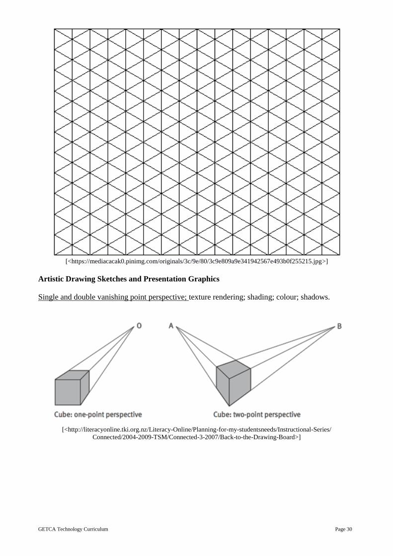
Artistic Drawing Sketches and Presentation Graphics
Single and double vanishing point perspective; texture rendering; shading; colour; shadows.
[<http://literacyonline.tki.org.nz/Literacy-Online/Planning-for-my-studentsneeds/Instructional-Series/
Connected/2004-2009-TSM/Connected-3-2007/Back-to-the-Drawing-Board>]

GETCA Technology Curriculum Page 31
8. Design
Architectural designer draw a two-dimensional birds-eye also known as a plan or a blue print or
plan-view of the house, or building as seen from above without the roof on. This view allows the
designer to decide on number of rooms, positions of bathroom relative to bedrooms and kitchen
relative to dining area.
[<http://r-m.info/wp-content/uploads/2015/12/amazing-modern-architecture-floor-plans-and-modern-
architectural-plans-jordan-floor-plan-17.jpg>]
Once the top or “plan” view has been completed, the designer then draws two-dimensional views
of the key sides of the house – termed “elevations”. There will be a “front elevation” showing the
house as seen from the front, and at least one other side, perhaps the “east elevation”. The number
of views will depend on the complexity of the design.
An RDP house needs no more than two elevations, while a complex mansion will need at least four
elevations.
When all working drawings are completed, the designer will draw an “artist’s impression” using
3D double vanishing point perspective. Colour and shading will be added to enhance the drawing
and texture rendering will be used to provide realism – wooden doors will be rendered to look like
wood and roof tiles will be rendered to look like slate or cement. These artistic drawings are
important because few house-buying clients can visualise the final appearance of the new house
they are having built when they look at two-dimensional working drawings.
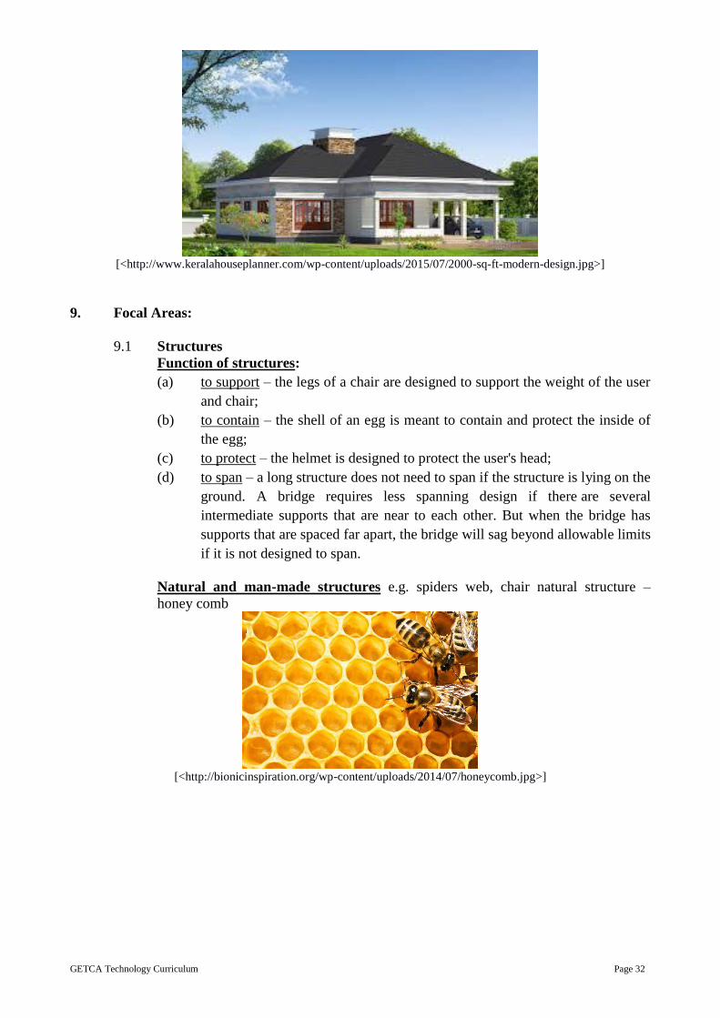
An important design concept in design is aesthetics; these are the characteristics of a product or
system that makes it look beautiful and attractive. When designing a product, ergonomics must be
considered. These are the features of a product or system that makes it user-friendly. Linked to this
are anthropometrics and these are the measurements of people’s shapes and sizes. Such
measurements are usually taken when products are designed for human use, e.g. furniture, eating
utensils, hairdryers, sporting equipment cars, clothing, etc.
GETCA Technology Curriculum Page 32
[<http://www.keralahouseplanner.com/wp-content/uploads/2015/07/2000-sq-ft-modern-design.jpg>]
9. Focal Areas:
9.1 Structures
Function of structures:
(a) to support – the legs of a chair are designed to support the weight of the user
and chair;
(b) to contain – the shell of an egg is meant to contain and protect the inside of
the egg;
(c) to protect – the helmet is designed to protect the user's head;
(d) to span – a long structure does not need to span if the structure is lying on the
ground. A bridge requires less spanning design if there are several
intermediate supports that are near to each other. But when the bridge has
supports that are spaced far apart, the bridge will sag beyond allowable limits
if it is not designed to span.
Natural and man-made structures e.g. spiders web, chair natural structure –
honey comb
[<http://bionicinspiration.org/wp-content/uploads/2014/07/honeycomb.jpg>]

GETCA Technology Curriculum Page 33
Man-made structure – power lines
[<https://www.vectorstock.com/royalty-free-vector/high-voltage-power-line-vector-265641>]
Types of structures:
Frame structures
Shell structures
Combination of frame and shell structures
Stone structures
Brick and block structures
Concrete structures
Metal
Composites
Forces:
In a structure we can define a force as anything that causes stress or compression in
a fixed body. There are different types of forces:
(a) Compression – push force
[<http://homeschool.scienceprojectideasforkids.com/wpcontent/uploads/
2012/02/forces-compression-tension.jpg>]
(b) Tension – pull force
(c) Torsion – this is the action of twisting, especially of one end of an object
relative to the other.
(d) Shear – A crack or tear may develop in a body from parallel shearing forces
pushing in opposite directions at different points of the body.
(e) Bending – Bending is the reaction when an external force is applied causing
the structure to bend.

GETCA Technology Curriculum Page 34
[<https://anotherdaywithmsk.files.wordpress.com/2014/04/screen-shot-2014-04-17-at-12-12-10-pm.png>]
Section 2. The force of gravity pulls everything downwards towards the earth.
There are forces acting on us all the time
Section 3. Force is measured in Newtons (N).
Reinforcing: struts and ties, using triangles as they create rigid shapes.
[<https://cnx.org/resources/3ea8615921167851da549dc484bfd198c00156c1/Picture%201.png>]
Stabilising: base size, base angles, centre of gravity, ground anchors.
Components of frame structures that span over space:
Beams-steel I-beams (girders), concrete lintels; beam and column bridge.
1. Arches – arches in buildings, bridges, and dam walls.
2. Columns – these can be anchored with good foundations and are usually
round or square
3. Structural failure – the three most likely ways structures fail are:
4. Fracture of a member – due to lack of strength.
5. Bending (flexing, buckling) – due to lack of stiffness (rigidity).
6. Toppling over – due to lack of stability (top heavy, narrow base).
7. Forces can be static or dynamic, and loads can be even or uneven.
Strengthening structures using folding, tubing, triangular webs and internal cross
bracing. (For the purpose of the Mini PAT, one way to do this is to use rolled
newspaper to make a model)
Strength of materials under the action of forces: compression, tension, torsion, and
shear. Strength of materials under the action of forces – metal cross-sections
Properties of construction materials: mass, density, hardness, stiffness, flexibility,
corrosion.
Suitability of materials: fitness-for-purpose in terms of properties, safety and cost
effectiveness.
Structural sections
Joints in wooden structures (16 wood joint animations)
Knock-down fittings
Joints in metal structures: welding, soldering and brazing, riveting, nuts, bolts,
and screws

GETCA Technology Curriculum Page 35
Some types of Bridges
Beam bridges
[<https://media1.britannica.com/eb-media/73/22073-004-F87F87E2.jpg>]
Continuous span bridge
[<https://upload.wikimedia.org/wikipedia/commons/thumb/3/33/
Parts_of_a_truss_bridge.svg/2000px-Parts_of_a_truss_bridge.svg.png>]
Simple span bridge
[<http://pghbridges.com/assets/images/bridgetypes/span_simple.GIF>]
Cantilever span bridge
[<https://upload.wikimedia.org/wikipedia/commons/e/e9/CooperRiverBridge.svg>]

GETCA Technology Curriculum Page 36
Cantilever with suspended span bridge
[<http://buildingstructures.weebly.com/uploads/1/6/4/4/16447926/2752311_orig.png>]
Cable stay bridge
[<http://www.technologystudent.com/images6/calesta2.gif>]
Suspension bridge
[<http://www.petervaldivia.com/structures>]
Practical tips to use paper to make structural models:
Stiffen a structural material by tubing. Newspaper rolled tightly
Stiffen a structural material by folding. Paper or card
Stiffen a frame structure by triangulation. Building using triangles

GETCA Technology Curriculum Page 37
9.2 Mechanical Systems and Control
Simple mechanisms:
Levers: first-, second- and third-class levers.
[<http://www.citytechnology.org/stuff-that-works/levers-have-a-lot-of-class>]
Examples of levers for each class
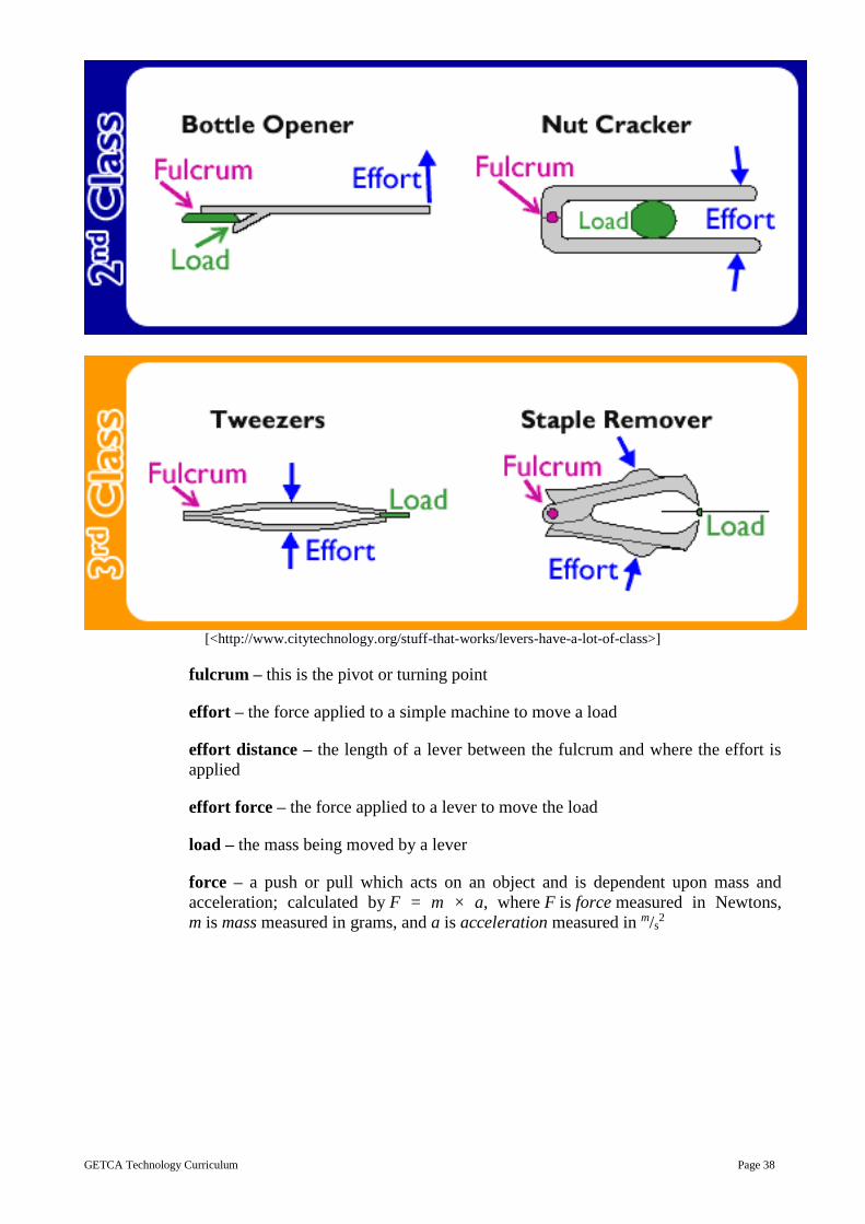
GETCA Technology Curriculum Page 38
[<http://www.citytechnology.org/stuff-that-works/levers-have-a-lot-of-class>]
fulcrum – this is the pivot or turning point
effort – the force applied to a simple machine to move a load
effort distance – the length of a lever between the fulcrum and where the effort is
applied
effort force – the force applied to a lever to move the load
load – the mass being moved by a lever
force – a push or pull which acts on an object and is dependent upon mass and
acceleration; calculated by F = m × a, where F is force measured in Newtons,
m is mass measured in grams, and a is acceleration measured in m/s2
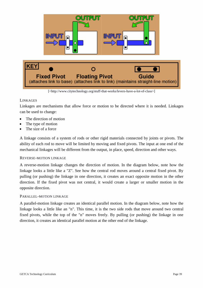
GETCA Technology Curriculum Page 39
[<http://www.citytechnology.org/stuff-that-works/levers-have-a-lot-of-class>]
LINKAGES
Linkages are mechanisms that allow force or motion to be directed where it is needed. Linkages
can be used to change:
The direction of motion
The type of motion
The size of a force
A linkage consists of a system of rods or other rigid materials connected by joints or pivots. The
ability of each rod to move will be limited by moving and fixed pivots. The input at one end of the
mechanical linkages will be different from the output, in place, speed, direction and other ways.
REVERSE-MOTION LINKAGE
A reverse-motion linkage changes the direction of motion. In the diagram below, note how the
linkage looks a little like a "Z". See how the central rod moves around a central fixed pivot. By
pulling (or pushing) the linkage in one direction, it creates an exact opposite motion in the other
direction. If the fixed pivot was not central, it would create a larger or smaller motion in the
opposite direction.
PARALLEL-MOTION LINKAGE
A parallel-motion linkage creates an identical parallel motion. In the diagram below, note how the
linkage looks a little like an "n". This time, it is the two side rods that move around two central
fixed pivots, while the top of the "n" moves freely. By pulling (or pushing) the linkage in one
direction, it creates an identical parallel motion at the other end of the linkage.

GETCA Technology Curriculum Page 40
[<http://www.technologystudent.com/images2/lnk2.gif>]
BELL-CRANK LINKAGE
A bell-crank linkage changes the direction of movement through 90°. By pulling (or pushing) the
linkage in one direction, it creates a similar movement at the other end of the linkage. For example,
a bell-crank linkage could be used to turn a vertical movement into horizontal movement, as in
a bicycle braking system.
[<http://www.dtonline.org/areas/6/1/20/p.gif>]
TREADLE LINKAGE
A treadle linkage shows how linkages can be used to change one type of motion into another. In
this case, the rotary motion of the cam moves a parallel-motion linkage. The parallel-motion
linkage controls the identical side-to-side, or oscillating motion, of two windscreen wipers.
[<https://www.bournetoinvent.com/projects/gcse_theory/7.html>]
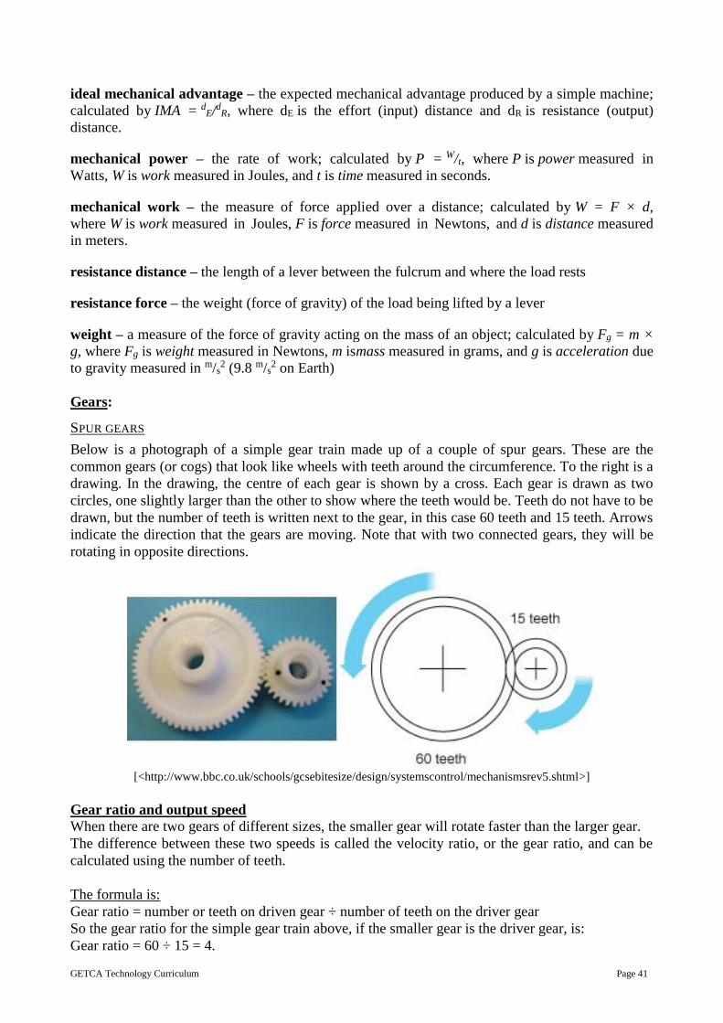
GETCA Technology Curriculum Page 41
ideal mechanical advantage – the expected mechanical advantage produced by a simple machine;
calculated by IMA = dE/dR, where dE is the effort (input) distance and dR is resistance (output)
distance.
mechanical power – the rate of work; calculated by P = W/t, where P is power measured in
Watts, W is work measured in Joules, and t is time measured in seconds.
mechanical work – the measure of force applied over a distance; calculated by W = F × d,
where W is work measured in Joules, F is force measured in Newtons, and d is distance measured
in meters.
resistance distance – the length of a lever between the fulcrum and where the load rests
resistance force – the weight (force of gravity) of the load being lifted by a lever
weight – a measure of the force of gravity acting on the mass of an object; calculated by Fg = m ×
g, where Fg is weight measured in Newtons, m ismass measured in grams, and g is acceleration due
to gravity measured in m/s2 (9.8 m/s
2 on Earth)
Gears:
SPUR GEARS
Below is a photograph of a simple gear train made up of a couple of spur gears. These are the
common gears (or cogs) that look like wheels with teeth around the circumference. To the right is a
drawing. In the drawing, the centre of each gear is shown by a cross. Each gear is drawn as two
circles, one slightly larger than the other to show where the teeth would be. Teeth do not have to be
drawn, but the number of teeth is written next to the gear, in this case 60 teeth and 15 teeth. Arrows
indicate the direction that the gears are moving. Note that with two connected gears, they will be
rotating in opposite directions.
[<http://www.bbc.co.uk/schools/gcsebitesize/design/systemscontrol/mechanismsrev5.shtml>]
Gear ratio and output speed
When there are two gears of different sizes, the smaller gear will rotate faster than the larger gear.
The difference between these two speeds is called the velocity ratio, or the gear ratio, and can be
calculated using the number of teeth.
The formula is:
Gear ratio = number or teeth on driven gear ÷ number of teeth on the driver gear
So the gear ratio for the simple gear train above, if the smaller gear is the driver gear, is:
Gear ratio = 60 ÷ 15 = 4.

GETCA Technology Curriculum Page 42
This means, the driver gear turns four times to make the driven gear turns once.
If you know the gear ratio, and the speed input at the driver gear, you can calculate the speed output
at the driven gear using the formula:
Output speed = input speed ÷ gear ratio
So, if the gear ratio is 4 and the driver gear is revolving at 200 rpm then the output speed = 200 ÷ 4
= 50 rpm
Compound gear train
If greater speed decreases are needed, several pairs of gears can be used in a compound gear train.
A small gear drives a large gear. The large gear has a smaller gear on the same shaft. This smaller
gear drives a large gear. With each transfer, the speed is significantly reduced.
[<http://www.bbc.co.uk/staticarchive/f00dffde0ef20de5200b04c48084113574f5edcf.gif>]
WORM GEARS
[<http://www.bbc.co.uk/schools/gcsebitesize/design/systemscontrol/mechanismsrev6.shtml>]
To reduce speed, a worm gear can be used. This is a shaft with a thread like a screw. It connects at
90° to a large spur gear. This works when the worm on the shaft spins one revolution, the gear
turns forward by one tooth. If the gear has 50 teeth, the gear ratio is 50:1. The worm can drive the
worm gear round, but the worm gear cannot drive the worm. This means that worm gears are good
to use in hoists, the load will not fall back when the motor stops. Worm gears are a good option
when you need to change direction or rotary motion through 90° and reduce the speed. The
photograph shows a worm gear powered by a motor.

GETCA Technology Curriculum Page 43
BEVEL GEARS
[<http://s.hswstatic.com/gif/gear-bevel.jpg>]
Bevel gears, like worm gears, change the axis of rotation by 90°. The teeth are specially cut so the
gears will mesh at right-angles.
Rack and pinion
A pinion is a round cog and the rack is a flat bar with teeth. The driver cog either moves along the
rack, for example a funicular railway – or else the driver cog moves the rack, as in the steering
system in cars. Rack and pinion changes rotary motion into linear motion – as shown in the
diagram below.
[<http://1.bp.blogspot.com/styVV1B2sU/TjFfCKCPLrI/
AAAAAAAAADo/0VMAKjbcc2M/s1600/15.png>]
Belt drive and chain system
[<http://www.technologystudent.com/images3/chain1.gif>]
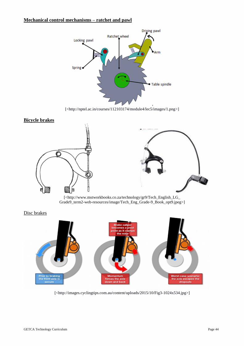
GETCA Technology Curriculum Page 44
Mechanical control mechanisms – ratchet and pawl
[<http://nptel.ac.in/courses/112103174/module4/lec5/images/1.png>]
Bicycle brakes
[<http://www.mstworkbooks.co.za/technology/gr9/Tech_English_LG_
Grade9_term2-web-resources/image/Tech_Eng_Grade-9_Book_opt9.jpeg>]
Disc brakes
[<http://images.cyclingtips.com.au/content/uploads/2015/10/Fig3-1024x534.jpg>]
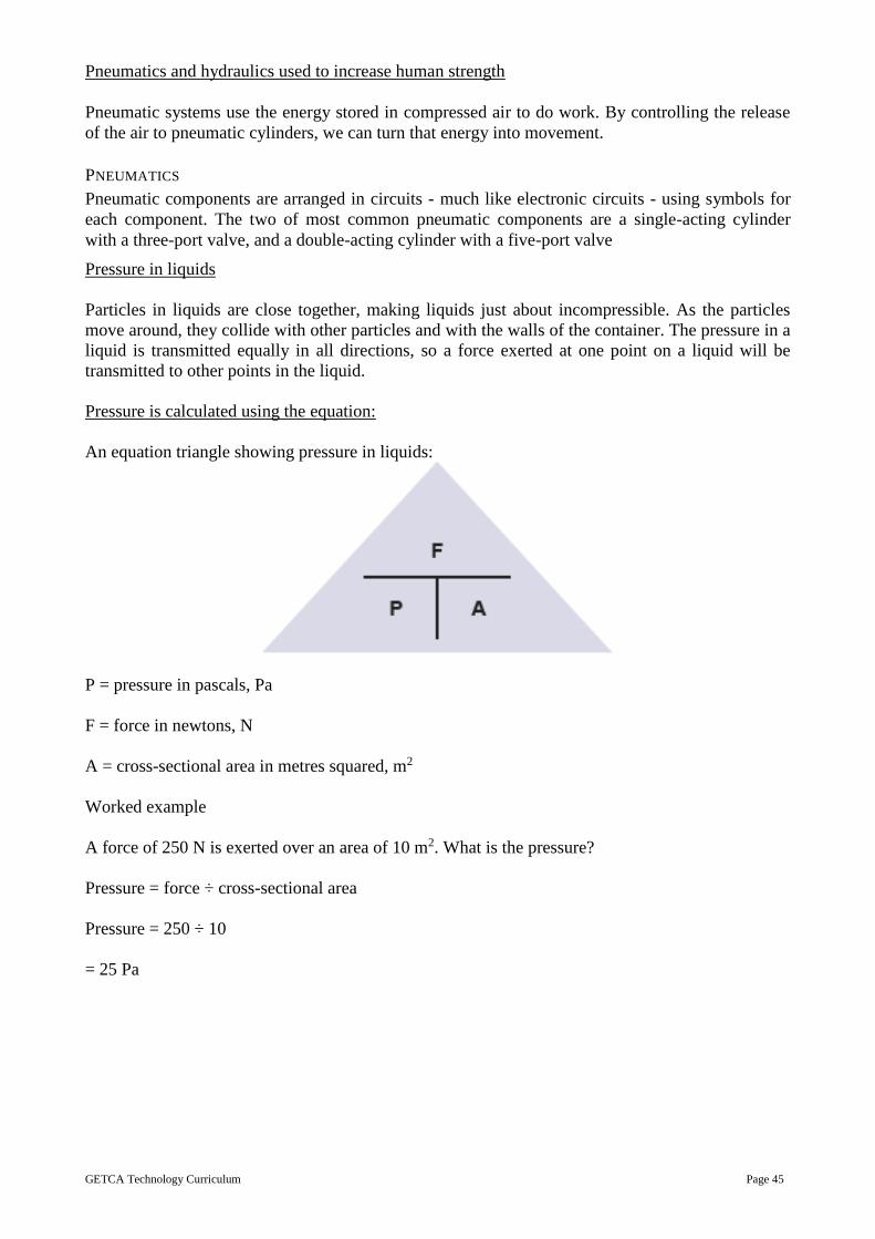
GETCA Technology Curriculum Page 45
Pneumatics and hydraulics used to increase human strength
Pneumatic systems use the energy stored in compressed air to do work. By controlling the release
of the air to pneumatic cylinders, we can turn that energy into movement.
PNEUMATICS
Pneumatic components are arranged in circuits - much like electronic circuits - using symbols for
each component. The two of most common pneumatic components are a single-acting cylinder
with a three-port valve, and a double-acting cylinder with a five-port valve
Pressure in liquids
Particles in liquids are close together, making liquids just about incompressible. As the particles
move around, they collide with other particles and with the walls of the container. The pressure in a
liquid is transmitted equally in all directions, so a force exerted at one point on a liquid will be
transmitted to other points in the liquid.
Pressure is calculated using the equation:
An equation triangle showing pressure in liquids:
P = pressure in pascals, Pa
F = force in newtons, N
A = cross-sectional area in metres squared, m2
Worked example
A force of 250 N is exerted over an area of 10 m2. What is the pressure?
Pressure = force ÷ cross-sectional area
Pressure = 250 ÷ 10
= 25 Pa

GETCA Technology Curriculum Page 46
HYDRAULICS
The pressure in a liquid is equally transmitted in all directions. This means that when a force is
applied to one point of the liquid, it will be transmitted to other points within the liquid.
A bucket, filled with water, has holes in it. The water coming from each hole gives out equal
pressure.
This principle can be exploited in hydraulic machines. Imagine that two syringes of different sizes
were connected by tubing and filled with water.
Two syringes showing force in and force out
An effort force exerted on the plunger for syringe A puts greater pressure on the water in tube A.
As water is virtually incompressible, the pressure is transmitted through the water into syringe B.
The water pushes against the plunger in syringe B with equal pressure, exerting a load force on it.
However, tube B has a plunger with a bigger cross-sectional area than tube A. This means that the
load force exerted is larger than the effort force exerted. This is known as a force multiplier.
Hydraulic systems therefore allow smaller forces to be multiplied into bigger forces. Note,
however, that the bigger syringe moves a shorter distance than the smaller syringe.

GETCA Technology Curriculum Page 47
Worked example
Study the diagram of the hydraulic jack. Calculate the force on piston B.
Hydraulic jack
Step 1: Calculate the pressure of the liquid inside piston A
Force in piston A
= 30 N
Cross-sectional area in piston A
= 0.2 pressure
= force ÷ cross-sectional area
pressure
= 30 ÷ 2
= 150 Pa
Step 2: Change the subject of the equation to find the force in piston B
Remember that the pressure within this closed system is transmitted equally in all
directions. Therefore the pressure in piston B is also 150 Pa.
Cross-sectional area in piston B = 1.0 m2 force
= pressure × cross-sectional area force
= 150 × 1.0
= 150 N
In this example, the hydraulic jack can lift load forces five times greater than the effort force put in.

GETCA Technology Curriculum Page 48
APPLICATIONS OF HYDRAULICS
It takes a large force to slow down or to stop a car that is travelling at speed. Hydraulics are used in
the braking system of a car. They cause a relatively small force from the driver’s foot to be
multiplied to produce a greater force, which acts equally on all four brake pads.
How car brakes work:
The force from the driver’s foot (the effort force) exerts pressure on the brake fluid in a
small piston. The pressure is transmitted throughout the brake fluid in all directions.
Next to each brake disc, there is a much larger piston with a greater cross-sectional area. The
transmitted pressure acts on this larger area to produce a larger load force on the brake pads. The
pads then rub against the brake discs and cause the car to slow down.
Hydraulic systems are also used in:
1 lifting equipment – e.g. hydraulic jacks and wheelchair lifts
2 lifting and excavating arms on machinery such as diggers
3 hydraulic presses – that are used during the creating of metal parts
4 wing flaps and some rudders on aircraft and boats

GETCA Technology Curriculum Page 49
Hydraulic grapple lifting scrap steel
[<http://www.bbc.co.uk/schools/gcsebitesize/science/triple_aqa/
using_physics_make_things_work/hydraulics/revision/3/>]
Hydraulic principles: incompressibility of liquids, pressure in liquids, force transfer.
Hydraulic/pneumatic systems that use restrictors, one-way valves: hydraulic press/jack.
Wheel and axle
[<http://01.edu-cdn.com/files/89501_89600/89547/file_89547.jpg>]

GETCA Technology Curriculum Page 50
Cams
[<http://www.technologystudent.com/images5/snlcam2.gif>]
[<http://image.slidesharecdn.com/srmpptoncamsforfirstyears-141124114046-
conversion-gate01/95/srm-ppt-on-cams-for-first-years-5-638.jpg?cb=1416829379>]
Cranks
[<http://cdn4.explainthatstuff.com/crank-animation.gif>]

GETCA Technology Curriculum Page 51
Pulley systems
Fixed pulley, moveable pulley, and multiple pulleys (block and tackle).
[<https://pulleyindia.files.wordpress.com/2015/10/different-types-of-pulley-systems.png>]
Systems where mechanical, electrical or pneumatic systems are combined.
Mechanical advantage – including simple calculations.
4.3 Electrical Systems and Control
Electrical circuit basics: Basic circuit components: cell(s), conductor, switch, resistor, lamp.
Simple circuit diagrams showing various component arrangements.
[<https://cdn.scratch.mit.edu/static/site/projects/thumbnails/5/7606.png>]
[<http://www.thunderboltkids.co.za/Grade6/03-energy-and-change/images/gd-0033.png>]

GETCA Technology Curriculum Page 52
Magnetism and magnetic metals: iron and steel, nickel, cobalt.
Introduction to electromagnetism: the electromagnet.
Circuit diagrams, conventions and component symbols.
Series circuit
[<http://www.bbc.co.uk/staticarchive/d9fa467a1c92f069b8abbcbbd55fb520b0ee2dc3.gif>]
Parallel circuit
[<http://cdn.instructables.com/FO6/5N6D/FRD86C0W/FO65N6DFRD86C0W.MEDIUM.gif>]
Input devices, control devices, output devices.
Circuits with more than one input or control device.
Electrical energy sources (including illegal connections):
Sources of direct current: electrochemical cells; photovoltaic cells.
Sources of alternating current: generating (thermal and alternate).
Distributing A.C electricity: the national grid, transformers (an application of electromagnetism).
Logic conditions:
AND logic (series); truth table.
OR logic (parallel); truth table.
Electronic systems and control – how simple electronic circuits and devices are used to make an
output respond to an input. Learners should be able to read a given electronic circuit diagram and
assemble the components into a working circuit.
Input components: electrochemical cells, photovoltaic cells.
Storage components: electrochemical cells, capacitors.
Control components: switches, resistors, diodes, light emitting diodes (LED), transistors.
Sensor components: thermistors, light dependent resistors (LDR).
Output components: lamp, buzzer/bell, light emitting diodes (LED).
Resistor codes.
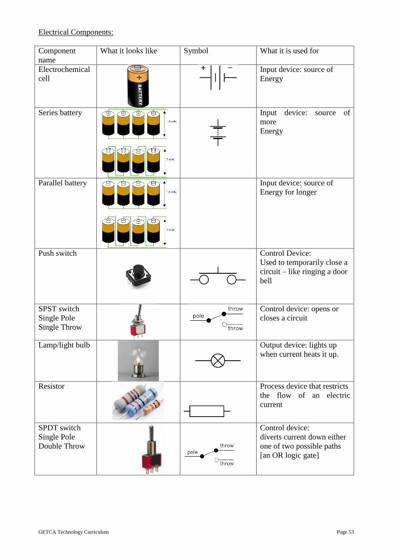
GETCA Technology Curriculum Page 53
Electrical Components:
Component
name
What it looks like Symbol What it is used for
Electrochemical
cell
Input device: source of
Energy
Series battery
Input device: source of
more
Energy
Parallel battery
Input device: source of
Energy for longer
Push switch
Control Device:
Used to temporarily close a
circuit – like ringing a door
bell
SPST switch
Single Pole
Single Throw
Control device: opens or
closes a circuit
Lamp/light bulb
Output device: lights up
when current heats it up.
Resistor
Process device that restricts
the flow of an electric
current
SPDT switch
Single Pole
Double Throw
Control device:
diverts current down either
one of two possible paths
[an OR logic gate]

GETCA Technology Curriculum Page 54
DPDT switch
Double Pole
Double Throw
Control device: diverts
current down either one of
two possible paths
[an OR logic gate]
Variable resistor
(rheostat)
Adjustable process device:
restricts the electric current,
e.g. stove switch
Bell and
Buzzer
Output device: vibrates to
give off sound when current
passes through it – useful as
an alarm
Motor
Output device: motor turns
converting electric energy
into kinetic energy
Voltmeter
(Connect in
PARALLEL)
Output device: meter
responds to potential
difference
Ammeter
(Connect in
SERIES)
Output device: meter
responds to current
Diode
Control device: allows
current to flow in one
direction only.
LED
(Light Emitting
Diode)
Control device: allows
current to flow in one
direction only, and emits
light
LDR
(Light
Dependent
Resistor)
Sensor: detects light;
resistance decreases in
bright light
Thermistor
+t OR -t
Sensor: detects heat:
+t: Hotter = more resistance
-t: Hotter = less resistance

GETCA Technology Curriculum Page 55
Touch or
Moisture
detector
Sensor: detects moisture
Transistor
npn
Control device: can act as a
switch or an amplifier
Capacitor
Polarised
Control device: can store
and release energy
(must be connected + to +)
How to read resistors:
[<https://cdn.instructables.com/FGG/TBC9/H4VQNQFG/FGGTBC9H4VQNQFG.MEDIUM.gif>]
Ohm’s Law: quantitative treatment with graphs and calculations.
[<http://www.electronics-tutorials.ws/dccircuits/dcp23.gif?81223b>]

GETCA Technology Curriculum Page 56
9.4 Processing
Recycling scrap metals – sorting ferrous and non-ferrous metals.
Improving properties of materials.
Improving the properties of wood: waterproofing.
Improving the properties of textiles: waterproofing, fire-resistance.
Improving properties of materials to adapt them to suit particular purposes:
Withstand forces – tension/compression/bending/torsion/shear
Positive and negative impacts of technological products on the environment and/or society.
Recycling: paper.
Adapt material for packaging of a product.
Extending lifespan:
Metal – paint, galvanise, and electroplate: Practical – preserving metal by electroplating.
Food – freeze, pickle, dry, salt: Practical – preserving food by drying/salting.
Types of plastics and their uses.
Recycling plastics to provide raw material for manufacture of new plastic products.
GUIDELINES FOR PRACTICAL ASSESSMENT TASKS
This section has the PAT tasks, which need to be covered for assessment purposes. The four focal
areas are covered and then a materials and tools list is provided. This should help to set up a
technology centre. The list provides the basics and can be built up over time. Whoever runs the
centre needs to make sure that if any items are to be ordered or purchased there is plenty time for
delivery. It is a good idea to make sure that the components; materials or tools needed are ordered
well in advance. Planning for practical tasks is imperative and the materials and tools must be well
organised for each adult student or team.
The four focal areas are set out to follow the technological process and outline what should be
assessed.
The four focal areas covered by the PATs.
1. Structures
2. Mechanisms and Control
3. Electrics and Control
4. Processing
Materials and Tools
Simple tools and cheap, preferably waste materials are all that will be required for this curriculum
to begin with. The following is a list to begin with. Later power tools could be purchased and
would be useful to use.
Adult students should be encouraged to manage with minimal supply levels as this develops
problem solving, lateral thinking and creativity.
Scissors
Craft knife with retractable blade
Junior Hack-saw and coping saw
Hammer
Safety ruler and ruler
Pliers, long nose and medium size
G-clamp

GETCA Technology Curriculum Page 57
Combination set square
Geometry set (for drawing)
Grid paper
Isometric 30grid paper for isometric drawings
H and B pencils and or clutch pencils
Pencil and felt tip colours
Screw driver
File
Sand paper
Glue
Glue gun and glue sticks
Chisel
Hand plane
Hand drill and drill bits
Metal shears
Staple gun
Safety goggles
Wire strippers
Soldering iron
Paint and brushes (water base if possible)
Paint trays or containers
Polystyrene vegetable trays to use for construction and to mix paint in
Colours – khoki and pencil
A3 and A4 paper for drawing
Card – a variety of colours
Newspaper for construction and for keeping surfaces clean
Wide work surfaces or tables
Access to water
Plug points [make sure that these are not overloaded]
Adhesives:
Glue Material to be
glued
Properties Setting
times
Commonly
known
brands
Solvents
Clear
cellulose
adhesive
Wood, cork,
leather, PVC
Waterproof,
heat resistant,
flammable
10 – 20
minutes
Bostik,
Pattex,
Thinners,
acetone
Contact
adhesives
Wood,
hardboard
plastic, metal
Heat resistant,
waterproof,
flammable
5 minutes Pattex,
Alcolin,
Thinners
Cyanoacrylic
“Superglue”
Plastic, glass,
ceramics
Fairly strong but
brittle, fails due to
vibrations
Instant Bostik Acetone
Epoxy resins Wood, metal,
glass, plastic
Very strong, heat
resist, waterproof
20 minutes
to 24 hours
Pratley,
Putty
None
PVA Wood, paper,
card, hardboard
Strong but not
heatproof nor
waterproof
20 – 60
minutes
Alcolin,
Pattex,
Ponal
Water –
before
fully dry.
Homemade
flour
Paste
Gluing paper,
papier-mâché
Cheap, suitable
for purpose
30 – 60
minutes
Water

GETCA Technology Curriculum Page 58
Working with metal
Metalwork is likely to be limited to small items – so there will be no need of bending machines and
guillotines. Adult students are likely to work with wire, small metal rods for axles, flat bar, round
bar, square bar, and lightweight metal sections, like angle iron. Metals used could include iron, tin,
copper and aluminium.
Cutting:
Junior hacksaw – preferably the type with vertical handle.
Hacksaw.
Metal snips/shears.
Side cutters – 160 mm.
Holding:
Engineer’s Vice – 100 mm jaws, fixed to bench.
Vice grips – 280 mm.
G-clamps – 100 mm and 250 mm jaws suit most jobs.
Combination pliers – 160 mm.
Needle nose pliers – 160 mm (for wirework).
Marking:
Scriber.
Compasses/dividers.
Guiding:
Try square – preferably with 450 mitre.
Combination square – measures 90 o, 45 o and depth.
Sliding “T” bevel – can be set at any angle.
Drilling:
Hand drill [wheel brace] – for drilling holes up to 4 mm in diameter.
Power drill – 350 – 500 W will be adequate – holes from 1 – 12 mm diameter.
Twist drills – set 1 – 12 mm – use only HSS grade for metals.
Joining:
Metals can be joined in a variety of ways:
Shifting spanner – 250 mm.
Bolting – a range of machine screws are available in brass or iron.
Suitable sizes depend on purpose: 15 mm to 40 mm are most common.
Riveting – using pop riveter and pop rivets, or hammered rivets.
Gluing – modern epoxy resins can bond metals very effectively.
Soldering – either using electric soldering iron or a gas flame.
Soldering iron stands; desoldering pump
Holding:
Carpenter’s vice.
Bench hook.
G-clamps – 100 mm and 250 mm jaws suit most jobs.
Sash clamps – 500 mm and 1 200 mm.
Marking tools:
Carpenters pencil.
Scriber.
Compasses/dividers.

GETCA Technology Curriculum Page 59
Guiding tools:
Try square – preferably with 45o mitre.
Combination square – measures 90°, 45° and depth.
Sliding “T” bevel – can be set at any angle.
Mitre box – a guide for the tenon saw when cutting 450 and 300 mitres.
Spirit level.
Measuring tools:
Steel tape – 3 m retractable.
Steel rule – 300 mm or 500 mm.
Cutting tools:
A tenon saw – the type with a ridged back is indispensable for many tasks.
A fretsaw – cuts curves and irregular shapes in thin wood – need spare blades.
A coping saw – similar to a fretsaw, but can be used to cut thicker wood.
Chisel set: range – 6 mm, 10 mm, 15 – 20 mm.
Smoothing:
Smoothing plane – steel with adjustable blade, about 44 mm wide.
Surform – easy-to-use tool with fixed-blade plane made by Stanley Tools.
Wood rasp – 250 mm half-round: For rough shaping – flat and concave curves.
Flat file – 150 mm fine cut – useful for model making.
Glass-paper – coarse to fine grades.
Drilling:
Bradawl – for starting small screws and marking pilot holes before drilling.
Hand drill [wheel brace] – for drilling holes up to 6 mm diameter.
Brace and bits – cut larger holes than the wheel brace 6 – 30 mm.
Twist drills – set 1 – 12 mm – note wood drills are not suitable for metals.
Countersink – to allow screw heads to lie flush with the surface.
Screwing:
Screw drivers – flat 3 mm, flat 5 mm, star (or cross head).
Wood screws – steel and brass – sizes according to needs – 15 mm to 50 mm.
Chipboard screws – steel – 15 mm to 40 mm.
Nailing:
Claw hammer [350 g] – claw is for pulling out nails.
Ball-peen hammer [300 g].
Cross-peen hammer [200 g] – useful light-weight hammer.
Pin punch – for sinking panel pinheads below the surface.
Panel pins – sizes: 12 mm, 19 mm.
Nails – sizes: 12 mm, 19 mm, 25 mm, 40 mm.
Working with acrylics and other plastics Acrylic plastics (e.g. Perspex) form a versatile group of materials for making plastic items. It can
be clear or coloured and can be sawn, drilled and filed into shapes easily. It is supplied in
transparent or opaque sheets, rods or tubes in wide variety of colours.
Oven gloves:
For handling Perspex heated for bending.

GETCA Technology Curriculum Page 60
Cutting & shaping:
Craft knife, coping saw, fret saw, hacksaw.
Files [flat, half round, needle].
Marking:
Ruler, scriber, setsquares, protractor, stencils, compass.
Drilling:
Hand drill, set of twist drills.
Bending:
Requires temperatures from 150° – 180° Celsius.
Holding:
G-clamps, bench vice, masking tape, double-sided tape.
Joining:
Acrylic cement [glue], silver or copper wire [for riveting].
Finishing:
Wet-or-dry abrasive paper in a range of grades:
– 240 coarse, 320 medium, 600 fine; and metal polish [e.g. Brasso].
Electrically Powered Tools
Electric drill: 450 – 600W with percussion.
Jig saw: Must have orbital action option and ability to plunge through undrilled surface.
Belt sander: 80 mm – avoid industrial strength equipment needing high skill and strength.
Orbital sander: 1/3-sheet machines are adequate.
Soldering Irons: Low power for electronics.
Scroll saw: Table model – used for wood and acrylics (more useful and safer than band saw)
Disc/belt sander Table model – 80 mm wide belt, 150 mm disc.
Bench grinder: Table model – one grinding wheel, one buffing wheel for acrylic work.
Hot plate: Two plate model.
Line bender: For bending acrylic plastics (very simple candle-heated models exist)
Vacuum former: For vacuum-forming using ABS plastic sheets.
Practical Tasks
Tasks need to be set up with a clear scenario with a problem that needs to be solved.
Once the problem has been understood, the adult students must work out the brief, specifications
and constraints.
The adult learners must then investigate options for solutions by doing some research.

GETCA Technology Curriculum Page 61
They then need to generate at least 2 different drawings with annotations to show how the problem
could be solved.
Final orthographic and or isometric drawings need to be produced. [Remember to include a
heading, labels/annotations and the correct layout. These may be produced in pencil or with fibre
tip pens or could even be done in colour]
A production schedule needs to be worked out for the team or for individual tasks. This is usually
done as a flow chart.
To begin the making process, the adult students must set out their work space and have all the tools
and materials they will use ready.
Detailed guidelines for PATs
Mini PAT 1: Structures
Context: Community Issues – The Contractors
Content: Identifying a problem within a given scenario
Simulation: This task deals with the design of a structure that will solve a problem facing a community living
on the far side of a river from the city. The local authority places an advertisement inviting
contractors to submit tenders for a solution.
Adult students form teams to act as ‘Contracting Companies’ that will compete for the contract to
solve the problem. If this is not possible adult students are to work individually.
The teams must be structured, with carefully designed roles for every adult student or they may
work individually.
Rationale: You do not need to be a member of a community in order to be able to address their needs –
engineering firms build bridges and stadia all over the world, and an architect can design an RDP
house without having to live in it. This task allows adult students to simulate the way the world
works with companies bringing appropriate technological solutions to problems wherever they
need to be solved. A number of problems may be identified and a range of solutions may work.
Costing is also part of design and learners at this level should consider real costs, including labour
– as this will help them to make informed career choices at this key point in their education, with
subject choices for FET especially important.
Investigation: 2 hours The tender process (including ethical practices):
Investigate: provide the scenario so that learners can investigate the problem situation and
various possible structures that could solve the problem(s) they identify. Analysis of existing
products relevant to the identified problem in terms of fitness-for-purpose (including suitability
of materials), safety for users, costs of materials and costs of construction. Realistic costs of
real materials, labour, transport, etc. Textbook writers must supply useful resources for this.
Design skills: 2 hours
Sketch initial ideas: each adult student generates two possible ideas.
Evaluate and adapt: teams evaluate individual ideas and develop a final idea.
Design brief: learners write a design brief with specifications for the final idea.
Flow chart: teams discuss how to proceed, and then each learner draws a flow chart.
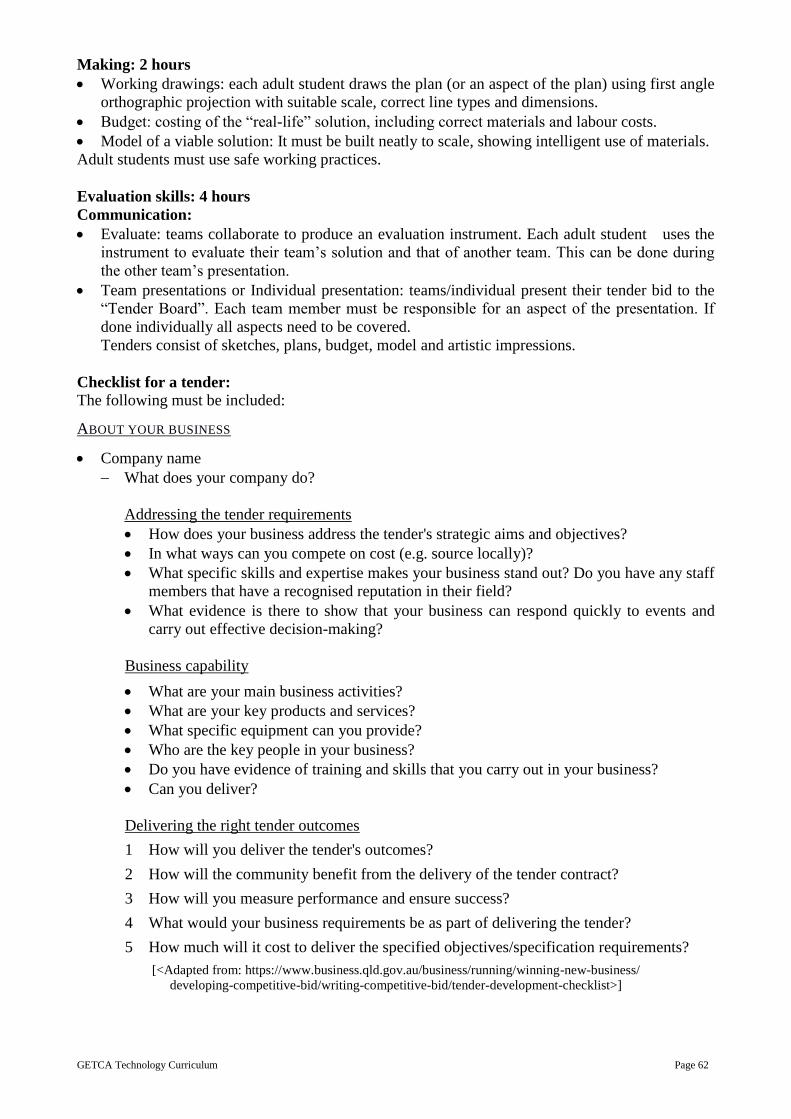
GETCA Technology Curriculum Page 62
Making: 2 hours
Working drawings: each adult student draws the plan (or an aspect of the plan) using first angle
orthographic projection with suitable scale, correct line types and dimensions.
Budget: costing of the “real-life” solution, including correct materials and labour costs.
Model of a viable solution: It must be built neatly to scale, showing intelligent use of materials.
Adult students must use safe working practices.
Evaluation skills: 4 hours
Communication:
Evaluate: teams collaborate to produce an evaluation instrument. Each adult student uses the
instrument to evaluate their team’s solution and that of another team. This can be done during
the other team’s presentation.
Team presentations or Individual presentation: teams/individual present their tender bid to the
“Tender Board”. Each team member must be responsible for an aspect of the presentation. If
done individually all aspects need to be covered.
Tenders consist of sketches, plans, budget, model and artistic impressions.
Checklist for a tender: The following must be included:
ABOUT YOUR BUSINESS
Company name
What does your company do?
Addressing the tender requirements
How does your business address the tender's strategic aims and objectives?
In what ways can you compete on cost (e.g. source locally)?
What specific skills and expertise makes your business stand out? Do you have any staff
members that have a recognised reputation in their field?
What evidence is there to show that your business can respond quickly to events and
carry out effective decision-making?
Business capability
What are your main business activities?
What are your key products and services?
What specific equipment can you provide?
Who are the key people in your business?
Do you have evidence of training and skills that you carry out in your business?
Can you deliver?
Delivering the right tender outcomes
1 How will you deliver the tender's outcomes?
2 How will the community benefit from the delivery of the tender contract?
3 How will you measure performance and ensure success?
4 What would your business requirements be as part of delivering the tender?
5 How much will it cost to deliver the specified objectives/specification requirements?
[<Adapted from: https://www.business.qld.gov.au/business/running/winning-new-business/
developing-competitive-bid/writing-competitive-bid/tender-development-checklist>]

GETCA Technology Curriculum Page 63
What to look for when assessing this PAT:
The following need to be considered: Communication, Design and Model
The following is a breakdown of what must be included in the rubric:
Brief
Specifications
Constraints
Idea drawings
Final Drawing
Model: meets the brief, specifications and constraints; it is neat and shows good workmanship; fit
for purpose and team work
Tender and tender board
Ideas for making structures:
Rolled newspaper; for this task one would need newspaper tightly rolled and secured with tape.
[<http://4.bp.blogspot.com/-puaSWCX-bsQ/VR1QNPAXSuI/AAAAAAAAAD4/
0zkIQ40G-EU/s1600/IMG_2159.png>]
Some examples of bridges made with newspaper rolls
[<http://www.cliftonbridge.org.uk/sites/cliftonbridge.org.uk/files/newspaper%20bridge.jpg>]

GETCA Technology Curriculum Page 64
Ice cream sticks
[<http://www.performersinschools.com.au/assets/paddle-pop-bridge.gif>]
Toothpicks and plastercine
Square wooden dowels
[<http://winkingfalcon.com/engineering%20web/1construction/bridges/images/L_BALSABRIDGE.jpg>]
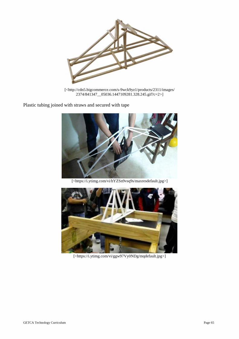
GETCA Technology Curriculum Page 65
[<http://cdn5.bigcommerce.com/s-9wck9yz1/products/2311/images/
2374/841347__05036.1447109281.328.245.gif?c=2>]
Plastic tubing joined with straws and secured with tape
[<https://i.ytimg.com/vi/hYZSn9vsq9s/maxresdefault.jpg>]
[<https://i.ytimg.com/vi/ggw97Vy0NDg/mqdefault.jpg>]

GETCA Technology Curriculum Page 66
Drinking straws and tape
[<https://s-media-cache-ak0.pinimg.com/236x/29/10/a3/2910a30e87ca4996f6fc63d97bfcc9b5.jpg>]
Drinking straws and tape
Drinking straws and tape
[<http://www.technologytom.com/assets/images/YAweb0002.jpg>]

GETCA Technology Curriculum Page 67
Drinking straws and tape
[<https://c1.staticflickr.com/5/4089/5043268149_4e1b381899_b.jpg>]
Mini PAT 2: Mechanical Systems and Control
Integrated Systems Duration of this lesson is one 30-minute period.
Topic: Systems where mechanical, electrical, hydraulic or pneumatic systems are combined.
Context: Will be given by materials developers
Content: Problem Solving/Mechanical Advantage
Scenario: Describe a scenario where a machine combining at least two of the following sub-
systems can be effective in giving a mechanical advantage to make work easier: mechanical,
electrical or pneumatic/hydraulic systems.
Note: The mechanical elements may consist of one or more of the following mechanisms: levers,
linked levers, wheels, cams, cranks, pulleys and/or gears.
The machine may include a mechanical or electrical control device like a cleat, ratchet and pawl, or
switch.
Investigation: 2hours
Investigate so that an appropriate machine can be designed to solve the problem, need or want
given in the scenario. Investigate the possible mechanisms and controls to be used together to
make the machine.
The design brief: each adult student writes a brief for the design and writes the specifications
and constraints. The brief should be set out as follows: Design and make … to solve…
Specifications and constraints are written in point form.
Design skills: 3 hours
Sketches: Produce two sketches of viable possible designs. Idea drawings do not have to be
drawn to scale but they must be as detailed as possible.
Teams meet and examine the individual suggestions and then decide on a final solution.
If working individually, the decision must be based on the brief, specifications and constraints
as well as the given scenario.
Making skills: 2 hours
Plan: working drawings
The teams/individual collaborate to produce drawings for their model/prototype using first
angle orthographic projection. To draw this accurately, use a geometry set and grid paper to set
it out correctly.

GETCA Technology Curriculum Page 68
Each team member draws a plan of the design OR, if it is very complex, one or more aspects of
the design. Each member must demonstrate her/his competency in using this drawing
technique.
Make: prototype/working model
The model can be made with any appropriate materials, but if possible, waste materials should
be used. Newspaper rolls fastened with tape, ice cream sticks glued with wood glue or Bostick
type glue, toothpicks and plastecine could be used. Other materials could include drinking
straws glued together with a glue gun or round or square dowels; these can be joined with wood
glue or a glue gun.
Learners use safe working practices.
Building: the model must showcase a viable solution to the problem. It should be to scale and
neat, and show intelligent use of available materials.
Communication skills: 2 hours
Team/individual presentations:
Each team or individual is given five minutes to present their solution in the form of sketches,
artistic impressions of the solution, working drawings/plans, costing and their model.
[Note that it is better to work in teams as this is a more realistic work situation, but if the adult
student is not able to work in a team because they may be doing the tasks as long distance
students, this may be the only option to them.]
Assessment: What to look for when assessing this PAT:
The following need to be considered: Investigate, Design, Make, Evaluate and Communicate
The following is a breakdown of what must be included in the rubric:
Investigation of various mechanisms used
Brief
Specifications
Constraints
Idea drawings
Final Drawing
Model: meets the brief, specifications and constraints; it is neat and shows good workmanship; fit
for purpose and team work
Evaluation of the model with self-reflection of workmanship and process

GETCA Technology Curriculum Page 69
Ideas for making mechanisms:
1. Levers and linkage
[<http://www.bookterra.com/images/1/13/SA_NC_Saaste_Modules_14.png>]
Use of levers to make the birds wings move
[<https://s-media-cach ak0.pinimg.com/564x/08/2f/f6/082ff6baf5aa1a5d947131f61bdbcb53.jpg>]

GETCA Technology Curriculum Page 70
Using linkages to make models move
[<http://www.plkclscmc.edu.hk/right/subjects/dt/modelmaking/linkage/linkage2/scissor2.JPG>]
2. Gears
Polystyrene discs with pins pushed in form the gears
[<https://s-media-cache-ak0.pinimg.com/236x/e8/73/86/e873861d66117f28b19da5bd69a9aa35.jpg>]

GETCA Technology Curriculum Page 71
Card cut gears
[<http://www.hometrainingtools.com/media/images/art/GearTrainYSE.jpg>]
Cardboard with corrugated card glued to the rim of the wheels
[<https://s-media-cache-ak0.pinimg.com/564x/80/3f/b8/803fb8e13be12e685df678ee3de6afa6.jpg>]
Card model
[<https://www.robives.com/sites/default/files/rootimages/dec2015/threegc-a26.jpg>]
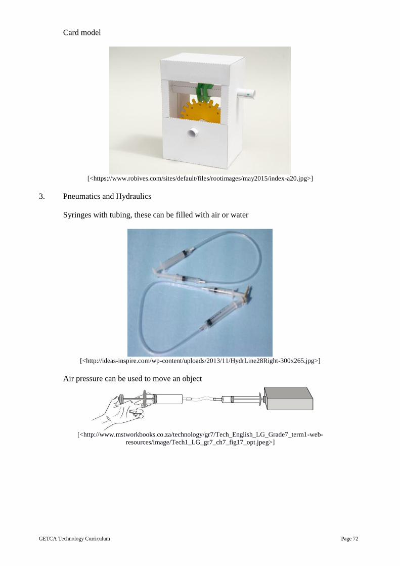
GETCA Technology Curriculum Page 72
Card model
[<https://www.robives.com/sites/default/files/rootimages/may2015/index-a20.jpg>]
3. Pneumatics and Hydraulics
Syringes with tubing, these can be filled with air or water
[<http://ideas-inspire.com/wp-content/uploads/2013/11/HydrLine28Right-300x265.jpg>]
Air pressure can be used to move an object
[<http://www.mstworkbooks.co.za/technology/gr7/Tech_English_LG_Grade7_term1-web-
resources/image/Tech1_LG_gr7_ch7_fig17_opt.jpeg>]

GETCA Technology Curriculum Page 73
A model made with syringes and tubing
[<http://www.miniscience.com/projects/MSLIFT/Pneumatic_Lift_L.jpg>]
A working pneumatic crane
[<http://www.technologytom.com/assets/images/17-8-10_088b.jpg>]
Mini Pat 3: Innovation: Electronic Systems and Control
Practical task: Electronic Systems Setting the scene Duration of this lesson is one 30-minute period.
This task involves a model where electrical and electronic systems are combined.
This may be integrated with other aspects like structures, etc.
Adult students are not expected to design an electronic circuit. They should assemble and connect
the components of a given circuit and design a suitable application for that circuit. The electronic
circuit may contain sensor devices and/or use transistor(s).
Scenario: Describe a situation where a given electronic circuit can be used to meet a need. Adult
students are given the task of building a given electronic circuit and finding an appropriate use for
this circuit.
Investigation: 2 hours
Design skills
Investigate the situation and the nature of the need so that an appropriate circuit can be chosen
to solve the problem, need or want given in the scenario.
A given circuit must be incorporated into the design of a device that will use the electronics to
address the problem, need or want.

GETCA Technology Curriculum Page 74
The design brief, specifications and constraints:
Each adult student should write suggestion for the design with specifications and constraints.
The brief should be set out as follows: Design and make … to solve …
Specifications and constraints are written in point form. Between three and five specification
need to be considered and three to five constraints.
Sketches
Draw the circuit diagram.
Produce a sketch in 3D showing the device that will use the electronic circuit.
Teams meet and examine the individual suggestions to decide on a final solution and make an
informed choice.
Making: 2 hours
Plans: working drawings and production schedule
Each adult student is to produce plans for their device/model/prototype using a first angle
orthographic projection. The plans should include a 3D “assembly” drawing in exploded view
showing how the model fits together.
Each team member is to draw a working diagram of the design OR an aspect of the design.
A viable production schedule should be drawn up using a flow chart.
Make: device /prototype/ working model with a circuit.
The model must showcase a viable solution to the problem. It should be to scale and neat, and
show intelligent use of available materials.
Communication: 2 hours
Team/ individual presentations:
Each team/ individual is given five minutes to present their solution in the form of sketches,
artistic impressions of the solution, working drawings/ plans, costing and their model.
Record Keeping: 2 hours
Each adult student must compile a record of his/her own individual contribution to the task.
This should be reflected in each adult student’s workbook.
What to look for when assessing this PAT:
The following need to be considered: Design and Make
The following is a breakdown of what must be included in the rubric:
Brief
Specifications
Constraints
Idea drawings
Final Drawing
Model: meets the brief, specifications and constraints; it is neat and shows good workmanship; fit
for purpose and team work
Mini-PAT 4: Reduce – Reuse – Recycle Practical task:
Working with Plastics Setting the scene Duration of this lesson is 30 minutes.
Scenario:
Describe a situation where cutting, joining, bending and/or moulding plastics can be used to make a
plastic product that will satisfy a need, want or opportunity.
Investigation: 2 hours
Case study: Look at plastics used on modern motorcars and plastics used around the home.

GETCA Technology Curriculum Page 75
Problem identification: identify a need or want that can be satisfied by the making of a plastic item
of own design.
Design: 2 hours
Making
Sketch: draw plastic item using isometric projection on grid paper.
Plan: draw plastic item using first angle orthographic projection.
Skills development: practise the skills needed to manufacture plastic item –measure, mark out,
cut, bend and join. Moulding is an optional extra.
Communication: 2 hours
Practical sessions: working safely, measure, mark out, cut and bend the materials for plastic
item, and then assemble the product.
Compiles a record of work including extending the lifespan of metals and food, properties and
uses of various plastics, the plastics recycling strategy, the case studies, and the sketches and
plans for the plastic item.
Assessment of PAT Tasks:
The following is a breakdown of what must be included in the rubric: Design and Make
Brief
Specifications
Constraints
Idea drawings
Rationale for choice
Final Drawing
Model: meets the brief, specifications and constraints; it is neat and shows good workmanship; fit
for purpose and team work.